Plastibeton Suggested Specifications - Oldcastle Precast
Plastibeton Suggested Specifications - Oldcastle Precast
Plastibeton Suggested Specifications - Oldcastle Precast

Create successful ePaper yourself
Turn your PDF publications into a flip-book with our unique Google optimized e-Paper software.
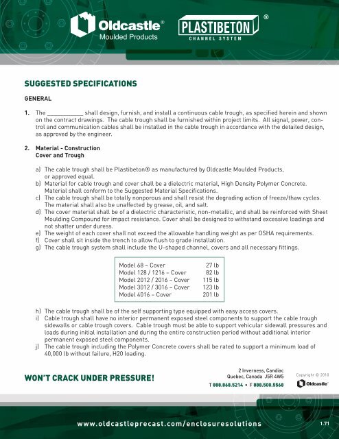
suggested specifications<br />
GENERAL<br />
1. The ___________ shall design, furnish, and install a continuous cable trough, as specified herein and shown<br />
on the contract drawings. The cable trough shall be furnished within project limits. All signal, power, control<br />
and communication cables shall be installed in the cable trough in accordance with the detailed design,<br />
as approved by the engineer.<br />
2. Material - Construction<br />
Cover and Trough<br />
a) The cable trough shall be <strong>Plastibeton</strong>® as manufactured by <strong>Oldcastle</strong> Moulded Products,<br />
or approved equal.<br />
b) Material for cable trough and cover shall be a dielectric material, High Density Polymer Concrete.<br />
Material shall conform to the <strong>Suggested</strong> Material <strong>Specifications</strong>.<br />
c) The cable trough shall be totally nonporous and shall resist the degrading action of freeze/thaw cycles.<br />
The material shall also be unaffected by grease, oil, and salt.<br />
d) The cover material shall be of a dielectric characteristic, non-metallic, and shall be reinforced with Sheet<br />
Moulding Compound for impact resistance. Cover shall be designed to withstand excessive loadings and<br />
not shatter under duress.<br />
e) The weight of each cover shall not exceed the allowable handling weight as per OSHA requirements.<br />
f) Cover shall sit inside the trench to allow flush to grade installation.<br />
g) The cable trough system shall include the U-shaped channel, covers and all necessary fittings.<br />
won’t crack under pressure!<br />
Model 68 – Cover 27 lb<br />
Model 128 / 1216 – Cover 82 lb<br />
Model 2012 / 2016 – Cover 115 lb<br />
Model 3012 / 3016 – Cover 123 lb<br />
Model 4016 – Cover 201 lb<br />
h) The cable trough shall be of the self supporting type equipped with easy access covers.<br />
i) Cable trough shall have no interior permanent exposed steel components to support the cable trough<br />
sidewalls or cable trough covers. Cable trough must be able to support vehicular sidewall pressures and<br />
loads during initial installation and during the entire construction period without additional interior<br />
permanent exposed steel components.<br />
j) The cable trough including the Polymer Concrete covers shall be rated to support a minimum load of<br />
40,000 lb without failure, H20 loading.<br />
2 Inverness, Candiac<br />
Quebec, Canada J5R 4W5<br />
T 888.868.5214 • F 888.500.5568<br />
www.oldcastleprecast.com/enclosuresolutions<br />
Copyright © 2010<br />
1.71
1.72<br />
k) Cable trough and cover shall be subjected to cycle testing to simulate vehicular traffic. Cover shall<br />
support 20,800 lb over a 10 x 10 sq. in., load applied 50 times and then final load applied anywhere on the<br />
cover until failure. Minimum failure point to be no less than 40,000 lb.<br />
l) The cable trough can be provided with integral dividers installed as per the end users location detail. Divider<br />
shall be manufactured utilizing Sheet Moulding Compound and be designed to support lateral loads<br />
from cables without any structural warping or deflections. Installation hardware shall be stainless bolts,<br />
round head, and countersunk to prevent any damage to cable sheathing.<br />
3. Installing Cable Trough<br />
a) The cable trough shall be installed by the contractor within the excavated trench as specified, on locations<br />
shown on the contract drawings, and as specified herein.<br />
b) The trench shall allow for the installation of crushed stone under and on the sides of the trough in accordance<br />
with the approved manufacturer’s recommendations and as approved by the Engineer.<br />
RAILROAD APPLICATIONS<br />
> The cable trough shall be installed with the top of the cable trough at least one inch below the bottom of all<br />
adjacent railroad ties.<br />
> In unballasted areas that are unaffected by rail renewal programs, the cable trough shall be installed with<br />
the top of the cable trough one inch below the finished grade.<br />
> In ballasted areas unaffected by rail replacement programs, the cable trough shall be installed as that the<br />
ballast can be tamped using heavy equipment without disturbing the cable trough. The ballast shall be so<br />
graded to allow free access to the cover of the cable trough.<br />
• Using a transit, prepare a line grade to set the channel at a level in the excavation.<br />
• If utilizing leveling blocks, place leveling blocks on compacted even surface, backfill around and to the height<br />
of leveling block and compact once again. Ensure that area between leveling blocks are leveled with no “hills<br />
or valleys” to guarantee a level surface.<br />
• Set the units into place on leveling blocks. The alignment of the sections shall be made with an instrument.<br />
• Backfill material placed on each side of the channel shall be done simultaneously. The backfill material shall<br />
be placed in four inch lifts and compacted.<br />
• Complete tamping the earth against the channel sidewalls and finish to final grade level with proper<br />
compactable materials.<br />
• Channel and covers must be maneuverable and can be cut on site with standard cutting equipment.<br />
• All backfill material shall be specified in Section 2M, Excavation - No Saturated Materials, no Ice.<br />
• Keep trench free and clear of construction debris, rocks, and earth or backfill materials. Remove foreign<br />
materials from trench prior to placing cables and covers.<br />
Copyright © 2010<br />
2 Inverness, Candiac<br />
Quebec, Canada J5R 4W5<br />
T 888.868.5214 • F 888.500.5568<br />
a system you can rely on!<br />
www.oldcastleprecast.com/enclosuresolutions
Property Test Method Test Result<br />
• Compressive strength ASTM C-170 Min. 17,000 psi<br />
• Modulus of elasticity in compression ASTM C-469 Min. 6.0 x 10 6 psi<br />
• Modulus of rupture ASTM C-99 Min. 5,800 psi<br />
• Direct tensile strength ASTM C-190 Min. 1,600 psi<br />
• Punching shear ASTM D-617 Min. 6,000 psi<br />
• Creep behaviour in flexure No effect at 60%<br />
of rupture after 2 months<br />
• Impact strength Min. 34 in-lb<br />
• Coefficient of expansion/contractor ASTM B-95 Max. 7 x 10 6 ºF -1<br />
• Water absorption ASTM C-97 Max. 0.31%<br />
• Specific gravity ASTM C-97 150 lb/ft 3 2.40<br />
• Fire resistance ASTM E-84 FSI 5 SD 30<br />
NFPA 130 Passed<br />
• Freeze/thaw resistance 1000 cycles ASTM C-666 No change<br />
• Scaling resistance 100 cycles ASTM C-672 No change<br />
• Sulphuric acid (50%) No significant change<br />
• Sodium hydroxide (5%) No significant change<br />
• Sodium sulphate (10%) No significant change<br />
• Sodium chloride (26%) No significant change<br />
American Society for Testing and Materials<br />
ASTM C-170 ASTM D-167<br />
ASTM C-469 ASTM B-95<br />
ASTM C-90 ASTM C-97<br />
ASTM C-190 ASTM E-84<br />
ASTM C-617 ASTM C-666<br />
Copyright © 2010<br />
1.70<br />
suggested material specifications<br />
2 Inverness, Candiac<br />
Quebec, Canada J5R 4W5<br />
T 888.868.5214 • F 888.500.5568<br />
a system you can rely on!<br />
www.oldcastleprecast.com/enclosuresolutions