EO-2034: Electric And Gas Services To D.C. Railroad ... - Con Edison
EO-2034: Electric And Gas Services To D.C. Railroad ... - Con Edison
EO-2034: Electric And Gas Services To D.C. Railroad ... - Con Edison

Create successful ePaper yourself
Turn your PDF publications into a flip-book with our unique Google optimized e-Paper software.
Q4 XJ<br />
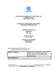
CONSOLIDATED EDISON COMPANY OF NEW YORK, INC.<br />
4 IRVING PLACE<br />
NEW YORK, N .Y. 10003<br />
DISTRIBUTION ENGINEERING DEPARTMENT<br />
NETWORK SYSTEMS SECTION<br />
SPECIFICATION <strong>EO</strong>-<strong>2034</strong><br />
REVISION 3<br />
OCTOBER. 1995<br />
ELECTRIC AND GAS SERVICES TO D.C. RAILROAD PROPERTIES<br />
FILE: APPLICATION AND DESIGN<br />
MANUAL NO. 4<br />
FIELD MANUAL 16, SECT. 4<br />
FIELD MANUAL 20, SECT. 3
APPLICATION AND DESIGN -2- <strong>EO</strong>-<strong>2034</strong>, REVISION 3<br />
MANUAL NO. 4 OCTOBER, 1995<br />
TABLE OF CONTENTS<br />
Paragraph Description<br />
1.0 PURPOSE<br />
2.0 APPLICATION<br />
3.0 DEFINITION<br />
4.0 GENERAL<br />
3.1 D.C <strong>Railroad</strong> Properties<br />
3.2 Facilities<br />
4.1 Stray Direct Current<br />
4.2 Remedy<br />
5.0 SECONDARY SERVICES<br />
5.1 Steel or Non-Metallic <strong>Con</strong>duits<br />
5.2 A.C. <strong>Con</strong>ductors<br />
5.2 A.C. Neutrals<br />
6.0 HIGH VOLTAGE FEEDERS<br />
6.1 Non-Metallic <strong>Con</strong>duits<br />
6.2 Lead Sheath Cables<br />
6 . 3 Sheath Break<br />
6.4 Sheath Insulating Joints<br />
7.0 GROUNDING<br />
7.1 Water Pipe<br />
7.2 Insulated A. C . Neutrals<br />
7.3 Old Railway Rectifier Substations<br />
7.4 Substations Installed Between 1950 and 1955<br />
7.5 Substations Installed Subsequent to 1955<br />
7.6 Metallic Water Piping Systems not Available
APPLICATION AND DESIGN -3- <strong>EO</strong>-<strong>2034</strong>, REVISION 3<br />
MANUAL NO. 4 OCTOBER, 1995<br />
8.0 GAS SERVICE PIPE<br />
9.0 WATER SERVICE PIPE<br />
1 0.0 ATTACHMENTS<br />
11.0 REFERENCE DRAWINGS
APPLICATION AND DESIGN - 4 - <strong>EO</strong>-<strong>2034</strong>, REVISION 3<br />
MANUAL NO. 4 OCTOBER, 1995<br />
1.0 PURPOSE<br />
ELECTRIC AND GAS SERVICES TO D.C RAILROAD PROPERTIES<br />
<strong>To</strong> provide the requirements for installation of electric and gas services to D.C. <strong>Railroad</strong><br />
Properties and prevent the flow of stray direct currents onto <strong>Con</strong> <strong>Edison</strong> facilities<br />
2.0 APPLICATION<br />
This specification applies to all Customer Service Operation areas.<br />
3.0 DEFINITIONS<br />
3.1 D.C. <strong>Railroad</strong> Properties consist of facilities operated by The Long Island<br />
<strong>Railroad</strong>, Metro North, Staten Island Rapid Transit, PATH, N.Y.C. Transit Authority<br />
and others.<br />
3.2 Facilities include yards, shops, substations, passenger stations, elevated structures,<br />
and any structure connected that may provide a path for stray D.C. current into the <strong>Con</strong><br />
<strong>Edison</strong> system.<br />
3.3 Property Line Splice - a point of termination which joins <strong>Con</strong> <strong>Edison</strong> primary<br />
supply cables to Customer-owned cables.<br />
4.0 GENERAL<br />
4.1 Stray Direct Current - Bare neutral cables, lead sheaths of insulated cables and<br />
metal pipes in contact with elevated or other railway structures may form an alternate<br />
path (i.e., a path with comparable d.c. resistance to the negative return circuit of the<br />
Transit system) for d.c. current returning to the originating Transit system substation.<br />
These "stray" currents can result in corrosion of Company cables, conduits and pipes via<br />
electrolysis. Furthermore, an electrical fault on the railway system could cause arcing<br />
damage to uninsulated cables, pipes, and metal conduits due to the flow of heavy fault<br />
currents.
APPLICATION AND DESIGN -5- <strong>EO</strong>-<strong>2034</strong>, REVISION 3<br />
MANUAL NO. 4 OCTOBER, 1995<br />
4.2 Remedy - Paragraphs 5.0 through 9.0 describe the action that is required to<br />
minimize the interchange of direct current between the two systems.<br />
5.0 SECONDARY SERVICES<br />
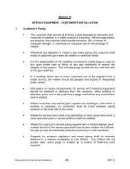
5.1 Steel or Non-Metallic <strong>Con</strong>duits may be used for secondary service cables. If steel<br />
conduits are used they shall be insulated from contact with metallic railroad structures,<br />
including the metal service end box, by means of phenolic insulation.<br />
5.2 A.C. <strong>Con</strong>ductors, including the neutral, shall be fully insulated. Leaded secondary<br />
cables or bare neutral conductors are not permitted.<br />
5.3 A.C. Neutrals shall be insulated and there shall be no metallic contact between it<br />
and any metal conduit or the metal service end box.<br />
6.0 . HIGH VOLTAGE FEEDERS<br />
6.1 Non-Metallic <strong>Con</strong>duits shall be used for high voltage cables from the Company<br />
manhole to the termination inside the station.<br />
6.2 Lead Sheath Cables shall be installed with a with a synthetic hose or polyethylene<br />
jacket over the sheath between the Company manhole and the equipment termination<br />
inside the station.<br />
6.3 A Sheath Break shall be provided on the high voltage cable on the Customer's side<br />
of the splice which joins the Company and <strong>Railroad</strong> cables. The Customer's side is the<br />
preferred location for the sheath break to assure that an operating fault at the property<br />
line splice will be readily detected by the <strong>Con</strong> <strong>Edison</strong>'s relay protection. The following<br />
specification drawings are referenced to show the method of performing a sheath break<br />
for various types of cable:<br />
6.3.1 <strong>EO</strong>-15367-B, "Method of Isolating Grounding on S/C, XLP Lead Cable and<br />
S/C XLP/EPR Non-Leaded Cable 15kV,27kV and 35kV."<br />
6.3.2 <strong>EO</strong>-13466-B, "Method of Isolating Lead Sheath on Single <strong>Con</strong>ductor, Paper<br />
Insulated, Lead Sheathed "Solid" Type Cable - 13kV, 27kV and 35kV."<br />
6.4 Sheath Insulating Joints, as an alternative to the sheath break, shall be
APPLICATION AND DESIGN -6- <strong>EO</strong>-<strong>2034</strong>, REVISION 3<br />
MANUAL NO. 4 OCTOBER, 1995<br />
7.0 GROUNDING<br />
provided on the high voltage cables at the splice which joins the <strong>Con</strong> <strong>Edison</strong> and<br />
<strong>Railroad</strong> cables.<br />
7.1 Water Pipe - The Customer's A.C. ground connection from the insulated A.C.<br />
neutral to the water service pipe shall be made on the street side of an insulating joint in<br />
the water service pipe.<br />
7.2 Insulated A.C. Neutrals shall not be used as grounds for <strong>Railroad</strong> D.C. equipment<br />
or D.C. apparatus windings or support brackets.<br />
7.3 Old <strong>Railroad</strong> Rectifier Substations (Type A) which were installed prior to 1950<br />
have a protective relay connected between the station ground bus and the water pipe.<br />
The grounding connection shall be made as shown on Drawing No. <strong>EO</strong>-5095-C, latest<br />
revision.<br />
7.4 Substations Installed Between 1950 and 1955 (Type B) with a separate A.C.<br />
ground bus shall have the A.C. service neutral and A.C. equipment casings connected to<br />
the A.C. ground bus and the water pipe as shown on Drawing No. <strong>EO</strong>5212-C, latest<br />
revision.<br />
7.5 Substations Installed Subsequent to 1955 shall have the A.C. service neutral and<br />
the A.C. equipment casings connected to the A.C. ground bus and water pipe as shown<br />
on Drawing No. <strong>EO</strong>-13728-C, latest revision.<br />
7.6 Metallic Water Piping System not Available - Where no metallic water piping<br />
system is available, an alternate method which provides a resistance to ground of not<br />
more than 25 ohms shall be used for the grounding connection.<br />
8.0 GAS SERVICE PIPE<br />
Insulating joints shall be installed at the property line in all gas service pipes to <strong>Railroad</strong><br />
properties.<br />
9.0 WATER SERVICE PIPE<br />
It is recommended that the Customer install an insulating joint in the water service pipe.
APPLICATION AND DESIGN -7- <strong>EO</strong>-<strong>2034</strong>, REVISION 3<br />
MANUAL NO. 4 OCTOBER, 1995<br />
10.0 ATTACHMENTS<br />
The following drawings are attached:<br />
<strong>EO</strong>-5095-C<br />
<strong>EO</strong>-5212-C<br />
<strong>EO</strong>-13728-C<br />
11.0 REFERENCE DRAWINGS<br />
<strong>EO</strong>-13466-B<br />
<strong>EO</strong>-15357-B<br />
SEE NEXT PAGE FOR SIGNATURE