EO-4019 - Con Edison
EO-4019 - Con Edison
EO-4019 - Con Edison

You also want an ePaper? Increase the reach of your titles
YUMPU automatically turns print PDFs into web optimized ePapers that Google loves.
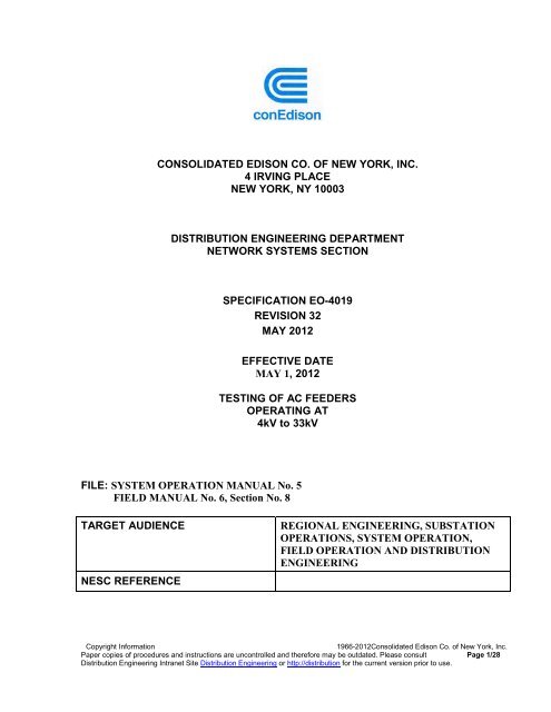
CONSOLIDATED EDISON CO. OF NEW YORK, INC.<br />
4 IRVING PLACE<br />
NEW YORK, NY 10003<br />
DISTRIBUTION ENGINEERING DEPARTMENT<br />
NETWORK SYSTEMS SECTION<br />
SPECIFICATION <strong>EO</strong>-<strong>4019</strong><br />
REVISION 32<br />
MAY 2012<br />
EFFECTIVE DATE<br />
MAY 1, 2012<br />
TESTING OF AC FEEDERS<br />
OPERATING AT<br />
4kV to 33kV<br />
FILE: SYSTEM OPERATION MANUAL No. 5<br />
FIELD MANUAL No. 6, Section No. 8<br />
TARGET AUDIENCE REGIONAL ENGINEERING, SUBSTATION<br />
OPERATIONS, SYSTEM OPERATION,<br />
FIELD OPERATION AND DISTRIBUTION<br />
ENGINEERING<br />
NESC REFERENCE<br />
Copyright Information 1966-2012<strong>Con</strong>solidated <strong>Edison</strong> Co. of New York, Inc.<br />
Paper copies of procedures and instructions are uncontrolled and therefore may be outdated. Please consult<br />
Distribution Engineering Intranet Site Distribution Engineering or http://distribution for the current version prior to use.<br />
Page 1/28
Specification Revision Rev Date Effective<br />
Date<br />
<strong>EO</strong> <strong>4019</strong><br />
32 5/1/2012<br />
TABLE OF CONTENTS<br />
PARAGRAPH DESCRIPTION<br />
1.0 SCOPE<br />
2.0 LIMITATIONS<br />
3.0 APPLICATION<br />
4.0 GENERAL<br />
5.0 DEFINITIONS<br />
6.0 PROOF TESTING<br />
6.1 Proof Testing For Acceptance Of New Cable<br />
6.2 Proof Tests Prior To Restoration To Service Of<br />
Existing Cable<br />
6.3 Exclusions to Maintenance Withstand Test<br />
7.0 AMMETER CLEAR TESTS<br />
8.0 EQUIPMENT TO BE DISCONNECTED PRIOR TO TESTS<br />
9.0 MEGGER TEST<br />
10.0 CALIBRATION OF MOBILE TEST EQUIPMENT<br />
11.0 TEST FACILITIES LEAKAGE MEASUREMENTS<br />
12.0 REFERENCES<br />
ATTACHMENTS<br />
TABLE I - VOLTAGE AND LEAKAGE CURRENT LIMITS<br />
TABLE IA - FOR MAINTENACE PROOF TEST OF CABLE, JOINTS AND<br />
TRANSFROMERS<br />
TABLE II - AMMETER CLEAR TEST<br />
TABLE III MODIFIED PROOF TEST VALUES<br />
APPENDIX A - CIOA GUIDELINE<br />
APPENDIX B - HI-POT TEST DATA SHEET<br />
Filing Information System Operations Manual No. 5<br />
Copyright Information Page<br />
2/28<br />
1966-2012<strong>Con</strong>solidated <strong>Edison</strong> Co. of New York, Inc.<br />
Paper copies of procedures and instructions are uncontrolled and therefore may be outdated. Please consult Distribution<br />
Engineering Intranet Site Distribution Engineering or http://distribution, for the current version prior to use.
1.0 SCOPE<br />
Specification Revision Rev Date Effective<br />
Date<br />
<strong>EO</strong> <strong>4019</strong><br />
32 5/1/2012<br />
TESTING OF AC FEEDERS<br />
OPERATING AT 4 kV to 33 kV<br />
1.1 This specification lists the tests to be performed on 4 kV to 33 kV AC feeders in<br />
the <strong>Con</strong> <strong>Edison</strong> system. These tests may be performed as required to:<br />
2.0 LIMITATIONS<br />
1.1.1 <strong>Con</strong>firm a failed feeder has been restored it to satisfactory insulation<br />
level, prior to energizing it back to service. This testing is referred to as<br />
a Maintenance Withstand Test.<br />
1.1.2 The second category of tests is performed on a new feeder to verify that<br />
its insulation meets acceptable limits. This testing is referred to as<br />
Routine Test.<br />
1.1.3 The Annual Testing Program for Network Feeders (Spring Hi-Pot<br />
program), will no longer be applied to network feeders. The program<br />
will be superseded by the Maintenance Withstand Test Protocol.<br />
1.1.4 4kV feeders are neither tested routinely nor on a scheduled basis. Hi-pot<br />
tests on 4kV feeders apply only to the portion of the feeder which is<br />
between the station and the first riser, referred to as the “station exit”<br />
part of the feeder. The Engineering Manager of Electric Operations of<br />
the regions shall select any 4kV feeders in their Region for a hi-pot.<br />
1.1.5 Test results for a Hi-Pot (Maintenance Withstand or Routine Test) will<br />
be recorded on an interval basis for DC Hi-Pot. Refer to Attachment B<br />
as an example. Note: For an AC Hi-Pot (VLF Withstand Test),<br />
manually recording the results will not be necessary as a print out can be<br />
generated by the test set equipment.<br />
This specification does not cover:<br />
• Fault locating.<br />
• Equipment in high tension customer installations beyond the first point of<br />
disconnection from the feeder. This equipment is covered in Specifications <strong>EO</strong>-<br />
2022 and <strong>EO</strong>-4035.<br />
Filing Information System Operations Manual No. 5<br />
Copyright Information Page<br />
3/28<br />
1966-2012<strong>Con</strong>solidated <strong>Edison</strong> Co. of New York, Inc.<br />
Paper copies of procedures and instructions are uncontrolled and therefore may be outdated. Please consult Distribution<br />
Engineering Intranet Site Distribution Engineering or http://distribution, for the current version prior to use.
• Proof testing of station electrical equipment and circuits in generating stations and<br />
substations unless such equipment is part of a feeder (refer to Specification EI-1002<br />
for proof testing of station electrical equipment).<br />
3.0 APPLICATION<br />
All Customer Service Regions.<br />
4.0 GENERAL<br />
4.1 The operating procedures described in this Specification shall be performed<br />
under the jurisdiction of the District Operator and in accordance with the<br />
General Instructions governing Work on System Electric Equipment.<br />
4.2 The Region’s Engineering Manager, <strong>Con</strong>trol Center Shift Manager or District<br />
Operator may waive “Proof Test” requirements based on system conditions.<br />
These conditions include, network feeder contingencies, local second or third<br />
conflicts, next contingency resulting in overloads or customer outages,<br />
customers out of service or extreme weather criteria. The waiver can be<br />
extended to apply to other extenuating circumstances. In this case, the reasons<br />
that dictated the waiver decision shall be entered in the <strong>Con</strong>trol Center’s Shift<br />
Managers log book for further reference and assessment of the decision.<br />
5.0 DEFINITIONS<br />
5.1 Ammeter Clear Test - The application of low voltage, 60 cycle, AC to a feeder<br />
to indicate the presence (or absence) of short circuits or grounds on the primary<br />
feeder conductors or on transformer secondaries. An ammeter clear test also<br />
detects a cross phase in a basket. (See Para 7.2)<br />
5.2 Megger Test - The application of 1000 volts DC for 5 minutes between one<br />
conductor and ground with the other conductors grounded, to measure<br />
insulation resistance.<br />
5.3 Proof Test - The application of a specific voltage for a specific time to cable<br />
and equipment to flush out incipient faults from the distribution system or, in<br />
the case of work in substation cubicles, to certify the proper insulation integrity<br />
of the installation. This test is preceded by an ammeter clear test.<br />
5.4 Feeder - The electric cable, station equipment and connected apparatus<br />
between the controlling circuit breaker or disconnecting device at a generating<br />
Specification Revision Rev Date Effective<br />
Date<br />
<strong>EO</strong> <strong>4019</strong><br />
32 5/1/2012<br />
Filing Information System Operations Manual No. 5<br />
Copyright Information Page<br />
4/28<br />
1966-2012<strong>Con</strong>solidated <strong>Edison</strong> Co. of New York, Inc.<br />
Paper copies of procedures and instructions are uncontrolled and therefore may be outdated. Please consult Distribution<br />
Engineering Intranet Site Distribution Engineering or http://distribution, for the current version prior to use.
station, substation, high tension customer installation, backfed transformer,<br />
underground step down transformer, and one or more of the following points:<br />
• The controlling circuit breaker or disconnecting device in another generating<br />
station or substation, or high tension customer installation.<br />
• The first circuit breaker or disconnecting device in the street.<br />
• The transformer or live-end cap at the ends of the cable if there is no circuit<br />
breaker or disconnecting device in the street.<br />
5.5 Feeder Mains -That portion of cable or wire, on the distribution system<br />
including spurs, beyond the first circuit breaker or disconnecting device in the<br />
street.<br />
5.6 Access Cover - A welded or bolted removable cover which permits access to<br />
electrical connections that are normally enclosed in a compartment or a tank.<br />
5.7 Station Work - Any work performed in the station that requires the deenergization<br />
of the associated feeder, such as:<br />
• Pothead connections and replacements.<br />
• Pothead to section bus connection work.<br />
• PT’s and CT’s work in the pothead compartment.<br />
• Bus work in the feeder compartment.<br />
• Feeder neons.<br />
• Removal or replacement of primary feeder bus tape that functions as<br />
primary insulation.<br />
• Physical inspection, removal and replacement of RMS coil.<br />
• Removal of access covers for visual inspections utilizing infrared<br />
equipment.<br />
• Addition or removal of equipment in the feeder compartment.<br />
5.8 Bifurcated Feeders - Two feeders with the same or different numbers<br />
emanating from the same circuit breaker. The legs may be designated L and M<br />
when the feeder number is identical.<br />
Specification Revision Rev Date Effective<br />
Date<br />
<strong>EO</strong> <strong>4019</strong><br />
32 5/1/2012<br />
Filing Information System Operations Manual No. 5<br />
Copyright Information Page<br />
5/28<br />
1966-2012<strong>Con</strong>solidated <strong>Edison</strong> Co. of New York, Inc.<br />
Paper copies of procedures and instructions are uncontrolled and therefore may be outdated. Please consult Distribution<br />
Engineering Intranet Site Distribution Engineering or http://distribution, for the current version prior to use.
5.9 Two-Legged Feeder - A feeder with capability to disconnect each of the legs<br />
in the substation via a link. Each of the legs bears a different feeder number.<br />
5.10 Dead Cable – Any underground cable installed in a condition or any aerial<br />
cable strung on a pole either of which has been de-energized for six months.<br />
5.11 Temperature Variable TV= 0.7(Tc) + 0.2(Tp1)+ 0.1(Tp2)<br />
Tc = Max effective Wet/Dry bulb temp. of current day<br />
Tp1 = Max effective Wet/Dry bulb temp. of 1 st prior day<br />
Tp2 = Max effective Wet/Dry bulb temp. of 2 nd prior day.<br />
5.12 Very Low Frequency (VLF) Proof Test – 0.1 Hz, cosine rectangular wave<br />
shape. 0.1 Hz AC hi-pot is recommended to be performed on feeders that<br />
contain more than 80% of solid dielectric cable. A VLF Withstand test should<br />
be used whenever a test set is available. A DC test should be performed only<br />
when a VLF test set is not available.<br />
6.0 PROOF TESTING<br />
6.1 Proof Testing For Acceptance Of New Cable - When a 4kV, 13kV, 27kV or<br />
33kV feeder is to be energized for the first time and consists of new cable, an<br />
ammeter clear test shall be performed followed by an acceptance proof test in<br />
accordance with the requirements stated in Table I. The addition to an existing<br />
feeder of a section(s) of “dead cable”, requires that the added section shall be<br />
proof tested either separately or as part of the feeder it is added to. The addition<br />
of new equipment to the feeder to be energized for the first time and consists of<br />
new cable also requires an acceptance test in accordance with the requirements<br />
stated in Table 1.<br />
6.2 Proof Tests Prior To Restoration To Service Of Existing Cable – A 4kV,<br />
13kV, 27kV or 33kV distribution feeders will be subjected to a Table 1A<br />
Maintenance Withstand test following:<br />
Specification Revision Rev Date Effective<br />
Date<br />
<strong>EO</strong> <strong>4019</strong><br />
32 5/1/2012<br />
• Any emergency feeder outage on that feeder, including: OA<br />
(Open-Auto), CIOA (Cut-In-Open-Auto), FOT (Fail-On-Test),<br />
OOE (Out-On-Emergency).<br />
• Any scheduled maintenance outage on that feeder.<br />
• For High Tension Customer. Test on customer premises in<br />
preparation for restoring equipment to service as per <strong>EO</strong>-4035.<br />
This test shall be made either at a voltage and time at least equal to<br />
the Company’s standard test value in effect at the time of test or in<br />
Filing Information System Operations Manual No. 5<br />
Copyright Information Page<br />
6/28<br />
1966-2012<strong>Con</strong>solidated <strong>Edison</strong> Co. of New York, Inc.<br />
Paper copies of procedures and instructions are uncontrolled and therefore may be outdated. Please consult Distribution<br />
Engineering Intranet Site Distribution Engineering or http://distribution, for the current version prior to use.
Specification Revision Rev Date Effective<br />
Date<br />
<strong>EO</strong> <strong>4019</strong><br />
32 5/1/2012<br />
accordance with the manufacturer’s recommended test criteria.<br />
This applies to: Any work that would disturb the insulation on any<br />
high tension equipment or cable which is directly connected to the<br />
Company’s supply feeder or is energized by closing the line circuit<br />
breaker or circuit closing device.<br />
• Feeders Automatically Removed from Service. If CIOA<br />
occurred after a successful modified hi-pot test, follow the CIOA<br />
guideline listed in PQ Website to determine if the tripping was<br />
due to inrush or not (See Appendix A).<br />
http://m020powerq/CIOA/Visio-CIOA guideline.pdf. The feeder<br />
should be Hi-Pot according to Table 1A.<br />
6.2.1 Feeders Manually Removed from Service for S or E <strong>Con</strong>dition<br />
Distinction is made between feeders taken out of service for S<br />
(Scheduled Work) or E (Emergency <strong>Con</strong>ditions) either at the station or<br />
in the field.<br />
6.2.1.1 Station Work – Two distinct cases are further recognized.<br />
A) The Station work did not affect any of the feeder clearances such as:<br />
• Replacement of neons.<br />
• Removal of all access covers for visual inspection utilizing<br />
infrared inspection equipment.<br />
• Inspections of RMS coils.<br />
• Replacement of RMS coils if the work is performed below the<br />
feeder cable pothead level.<br />
• Application and removal of portable grounds.<br />
In all cases mentioned above, where visual inspection by a substation<br />
operator confirms that clearances have not been disturbed, the feeder<br />
does not require a Hi-pot test prior to restoration unless “Field Work”<br />
has been performed as per Para 6.2.1.2<br />
B) The Station work has disturbed the feeder clearances. In this case, a<br />
maintenance withstand hi-pot test (Table 1A) shall be performed prior to<br />
restoring the feeder to service.<br />
Filing Information System Operations Manual No. 5<br />
Copyright Information Page<br />
7/28<br />
1966-2012<strong>Con</strong>solidated <strong>Edison</strong> Co. of New York, Inc.<br />
Paper copies of procedures and instructions are uncontrolled and therefore may be outdated. Please consult Distribution<br />
Engineering Intranet Site Distribution Engineering or http://distribution, for the current version prior to use.
6.2.1.2 Field Work - Feeders taken out of service for “Scheduled<br />
Work”, “When Ready”, OOE Category I or II where work was<br />
performed (such as modifications to cable splices, transformer<br />
replacements, Green Sheet jobs, replacing switches on a pole or new<br />
equipment pick-ups requires a maintenance withstand test (Table 1A) to<br />
be performed prior to restoring the feeder to service.<br />
6.2 Exclusions to Maintenance Withstand Test - Exclusions to the Maintenance<br />
Withstand protocols, where it is not required to perform a Maintenance<br />
Withstand test:<br />
1. Test duration of five minutes will be applied to all Withstand tests<br />
performed during the summer period, May 15 through September 15, or<br />
when dictated by system conditions that include: potential schedule conflicts<br />
and system contingencies<br />
2. When required by system operation conditions, which include: multiple<br />
feeder contingences or feeder scheduling conflicts, withstand tests following<br />
schedule work or OOE outages may be waived.<br />
3. For 13kV feeders operating in Westchester, the Table 1 and/or 1A test<br />
Voltage may be reduced to 10 kV if either there is a grounding transformer<br />
on the circuit to be tested or the tested feeder has no backfeed source.<br />
4. Following a scheduled maintenance outage that involves multiple feeders,<br />
where the outage work does not relate directly to the feeders. This exclusion<br />
could be applied to, for example, a Bus Section outage at the substation.<br />
5. Following a scheduled maintenance outage on a single feeder that did not<br />
expose the cable conductor (break copper), disconnect the neutrals,<br />
significantly move the cable, or require the removal/repositioning of splice<br />
sleeves.<br />
7 AMMETER CLEAR TEST<br />
7.1 A satisfactory proof test is in itself evidence that the feeder is clear of grounds on its<br />
primary side. However, it does not provide confirmation that grounds on the<br />
secondary side have been removed, nor can it be construed as evidence that<br />
transformer secondaries are clear of shorts. It is for this reason, that an ammeter<br />
clear test may be required regardless of whether or not a proof test is required.<br />
7.2 <strong>Con</strong>versely a satisfactory ammeter clear test is evidence that the feeder is clear of:<br />
Specification Revision Rev Date Effective<br />
Date<br />
<strong>EO</strong> <strong>4019</strong><br />
32 5/1/2012<br />
Filing Information System Operations Manual No. 5<br />
Copyright Information Page<br />
8/28<br />
1966-2012<strong>Con</strong>solidated <strong>Edison</strong> Co. of New York, Inc.<br />
Paper copies of procedures and instructions are uncontrolled and therefore may be outdated. Please consult Distribution<br />
Engineering Intranet Site Distribution Engineering or http://distribution, for the current version prior to use.
• Short circuits on feeder conductors including accidental short circuits, which<br />
might occur when work is done involving removal of access covers.<br />
• Low resistance grounds on feeder conductors and connected apparatus.<br />
• Short circuits resulting from incorrect phase relationship in the splicing of<br />
one section relative to the other section of a feeder having sections of cable<br />
in parallel. (i.e. Cable splicing in a basket)<br />
• Short circuits on conductors at a point beyond a transformer connected to a<br />
feeder, such as short circuits applied to the secondaries of a network<br />
transformer bank, or secondary grounds.<br />
7.3 Prior to any proof testing, an ammeter clear test shall be performed on all AC<br />
feeders. The results of the test shall conform to the requirements stated in Table II.<br />
7.4 As per section 9.4.8 of the “General Instructions Governing Work on the Electrical<br />
System”, an ammeter clear test may be waived if the ammeter clear test would<br />
delay the restoration of the feeder for more than 10 minutes.<br />
7.5 An ammeter clear test is not required prior to raising voltage on a feeder as part of<br />
the insulation breakdown process required to establish a condition following an OA<br />
or FOT.<br />
7.6 An ammeter clear test may be waived if any grounds applied are visible and can be<br />
verified as removed:<br />
• Providing that no “Field Work” has been performed as per Paragraph<br />
6.2.1.2 and/or<br />
• Providing that no “Station Work” involving the disturbances of any<br />
clearances has been performed as per Paragraph 6.2.1.1.<br />
7.7 Method of Test – An alternating current ammeter clear test is made by applying<br />
120 volts, 60 hertz derived from a grounded neutral source, to each conductor of a<br />
feeder through an ammeter and a resistor adjusted to limit the short-circuit current<br />
to 5 amperes. The test is applied to each conductor separately while the other<br />
conductors are grounded at the point where the test is applied. In stations having<br />
low voltage testing boards, with an ammeter clear selector switch, only one of the<br />
two other conductors can be grounded. The condition of the ammeter test set shall<br />
be checked for grounds and continuity before and after each test<br />
Specification Revision Rev Date Effective<br />
Date<br />
<strong>EO</strong> <strong>4019</strong><br />
32 5/1/2012<br />
Filing Information System Operations Manual No. 5<br />
Copyright Information Page<br />
9/28<br />
1966-2012<strong>Con</strong>solidated <strong>Edison</strong> Co. of New York, Inc.<br />
Paper copies of procedures and instructions are uncontrolled and therefore may be outdated. Please consult Distribution<br />
Engineering Intranet Site Distribution Engineering or http://distribution, for the current version prior to use.
8 EQUIPMENT TO BE DISCONNECTED PRIOR TO TESTS<br />
The following apparatus shall be disconnected as indicated, prior to performing a proof<br />
test or a Megger test on any distribution feeder:<br />
Station Equipment <strong>Con</strong>nected to Feeder<br />
Specification Revision Rev Date Effective<br />
Date<br />
<strong>EO</strong> <strong>4019</strong><br />
32 5/1/2012<br />
Apparatus Operation<br />
Station transformer, potential<br />
transformer, regulator, load ratio<br />
transformer, lightning arrestor,<br />
shunt reactor or shunt capacitor<br />
Filing Information System Operations Manual No. 5<br />
Disconnect apparatus, if<br />
disconnecting facilities exist.<br />
Transformer Disconnect neutral ground links<br />
of transformer if so equipped put<br />
the neutral grounding switch in<br />
the neutral open position.<br />
Grounding Transformer Remove ground connection from<br />
high voltage side neutral bushing<br />
and close short-circuiting switch<br />
on low voltage side, if so<br />
equipped.<br />
Coupling Capacitors and<br />
Potential Devices<br />
Close the primary ground switch<br />
of the coupling capacitor or<br />
potential device.<br />
Copyright Information Page<br />
10/28<br />
1966-2012<strong>Con</strong>solidated <strong>Edison</strong> Co. of New York, Inc.<br />
Paper copies of procedures and instructions are uncontrolled and therefore may be outdated. Please consult Distribution<br />
Engineering Intranet Site Distribution Engineering or http://distribution, for the current version prior to use.
Distribution Equipment <strong>Con</strong>nected to Feeder<br />
Specification Revision Rev Date Effective<br />
Date<br />
<strong>EO</strong> <strong>4019</strong><br />
32 5/1/2012<br />
Apparatus Operation<br />
Distribution and potential<br />
transformer and regulator with<br />
a wye-connected primary and<br />
grounded neutral. Potential<br />
devices wired to ground<br />
Filing Information System Operations Manual No. 5<br />
Disconnect and insulate the<br />
neutral or disconnect transformer<br />
or regulator. When primary and<br />
secondary neutrals are connected<br />
together inside the transformer<br />
tank, the transformer must be<br />
disconnected.<br />
Shunt Reactor Open neutral ground switch.<br />
Grounding Transformer Open neutral ground switch.<br />
Auto-transformer Disconnect transformer from<br />
higher voltage cable whenever<br />
higher voltage cable is to be<br />
tested, and disconnect neutral<br />
when low side is tested.<br />
Lightning/Surge Arrestor Disconnect lightning/surge<br />
arrestor.(refer to Note E<br />
following Table 1)<br />
Capacitor Disconnect capacitor<br />
High tension customer’s<br />
equipment beyond first<br />
disconnecting device on<br />
customer premises. (refer to Note<br />
H following Table 1)<br />
Open first disconnecting device.<br />
Copyright Information Page<br />
11/28<br />
1966-2012<strong>Con</strong>solidated <strong>Edison</strong> Co. of New York, Inc.<br />
Paper copies of procedures and instructions are uncontrolled and therefore may be outdated. Please consult Distribution<br />
Engineering Intranet Site Distribution Engineering or http://distribution, for the current version prior to use.
9 MEGGER TEST<br />
9.1 A 1,000-volt DC megger test set can be used to measure the insulation resistance of<br />
a feeder. Voltage is applied between each conductor separately and ground while<br />
the other conductors are grounded at the point where the test is applied. The<br />
minimum satisfactory insulation resistance can be found in Table 1 of Specification<br />
EI-1002.<br />
9.2 A megger test may be substituted for an ammeter clear test where a 4kV or 13kV<br />
underground feeder is supplied by a step-down transformer through a vacuum<br />
interrupter switch. It shall be made on the load side of the switch after all<br />
equipment has been disconnected from the feeder as per Paragraph 8.0. The test<br />
shall be conducted for a time period of one minute and voltage shall be applied to<br />
each phase with the other two phases grounded. The minimum satisfactory<br />
resistance shall be 4 megohms for 4kV feeders and 15 megohms for 13kV feeders.<br />
10 CALIBRATION OF MOBILE TEST EQUIPMENT<br />
10.1 The proof test equipment shall be operated with sphere gaps attached which<br />
have been set at an air gap spacing (in millimeters) determined from graphs used for<br />
calculating the distance. It shall be set at a voltage no greater than 10% above the<br />
required proof test voltage.<br />
10.2 All mobile test equipment shall be calibrated annually by the Instrumentation<br />
and Material Testing Laboratories Services Department.<br />
11 TEST FACILITIES LEAKAGE MEASUREMENTS<br />
11.1 Prior to the application of a proof test, test facilities leakage measurements shall<br />
be made at proof test voltage for five minutes.<br />
11.2 Upon the completion of the proof test, test facilities leakage measurements shall<br />
be made at proof test voltage for five minutes.<br />
11.3 If the elapsed time for making a test on a feeder should exceed three hours,<br />
additional leakage measurements shall be made on the test facilities at<br />
approximately three-hour intervals.<br />
11.4 At stations with ammeter test sets, the condition of the test set shall be checked<br />
for grounds continuity before and after each test.<br />
Specification Revision Rev Date Effective<br />
Date<br />
<strong>EO</strong> <strong>4019</strong><br />
32 5/1/2012<br />
Filing Information System Operations Manual No. 5<br />
Copyright Information Page<br />
12/28<br />
1966-2012<strong>Con</strong>solidated <strong>Edison</strong> Co. of New York, Inc.<br />
Paper copies of procedures and instructions are uncontrolled and therefore may be outdated. Please consult Distribution<br />
Engineering Intranet Site Distribution Engineering or http://distribution, for the current version prior to use.
12 REFERENCES<br />
The following specifications are listed for reference purposes:<br />
SPEC. NO. TITLE FILED IN<br />
EI-1002 Specification of Proof Testing<br />
of Station Electric Equipment<br />
and Circuits.<br />
<strong>EO</strong>-1184 Distribution U/G Cables & Jt.<br />
Insp. C&D Faults<br />
<strong>EO</strong>-2022 General Specification for High<br />
Tension Service<br />
<strong>EO</strong>-4035 Operating and Maintenance of<br />
Equipment on High Tension<br />
Customer’s Premises.<br />
<strong>EO</strong>-10808 Adding, Replacing and Reconditioning<br />
Insulating Oil<br />
Leeman Hong<br />
Samuel King-Nabi//<br />
Specification Revision Rev Date Effective<br />
Date<br />
<strong>EO</strong> <strong>4019</strong><br />
32 5/1/2012<br />
Filing Information System Operations Manual No. 5<br />
Station Electric<br />
Section Manual<br />
Operation and<br />
Maintenance<br />
Manual No. 1<br />
Application & Design<br />
Manual No. 4<br />
System Operation<br />
Manual No. 5<br />
Operation & Maintenance<br />
Manual No. 1<br />
Patrick G. McHugh (Signature on File)<br />
Patrick G. McHugh<br />
Chief Engineer<br />
Distribution Engineering Department<br />
Copyright Information Page<br />
13/28<br />
1966-2012<strong>Con</strong>solidated <strong>Edison</strong> Co. of New York, Inc.<br />
Paper copies of procedures and instructions are uncontrolled and therefore may be outdated. Please consult Distribution<br />
Engineering Intranet Site Distribution Engineering or http://distribution, for the current version prior to use.
TABLE I<br />
VOLTAGE AND LEAKAGE CURRENT LIMITS<br />
FOR PROOF TESTS OF 4 KV TO 33 KV FACILITIES<br />
(Refer to paragraph 9.0 for apparatus to be disconnected prior to test).<br />
NOMINAL TEST VOLTAGE<br />
OPERATING ACCEPTABLE<br />
VOLTAGE DC 0.1 Hz VLF DC & VLF AC<br />
BETWEEN TEST AC TEST LEAKAGE REMARKS<br />
(See Notes C,D,E,F,G and<br />
CONDUCTORS (kV) (kV) DURATION MILLIAMPS H)<br />
(VOLTS) (Note A) (MINUTES) (Note B)<br />
4,000 10 10 5 5 Between all conductors<br />
connected together and<br />
ground.<br />
13,800** 30 25 15 15 (Dist. Between all conductors<br />
(refer to Fdrs.) connected together and<br />
Note F) 5 (Tie ground.<br />
Fdrs.)<br />
27,000 50 50 15 15 (Dist. Between all conductors<br />
(refer to Fdrs.) connected together and<br />
Notes F 5 (Tie ground.<br />
and G) Fdrs.)<br />
33,000 60 60 15 5 On 3 conductor cable<br />
(refer to or where 3 single con<br />
Note F) ductor cables are in<br />
1 duct, test between<br />
all 3 conductors connected<br />
together and ground. On<br />
single conductor cable in<br />
separate ducts, test<br />
between phase and<br />
ground with the other<br />
phases grounded.<br />
** For 13kV feeders operating in Westchester, the Table 1 test Voltage may be reduced to 10<br />
kV if either there is a grounding transformer on the circuit to be tested or the tested feeder has<br />
no backfeed source.<br />
Specification Revision Rev Date Effective<br />
Date<br />
<strong>EO</strong> <strong>4019</strong><br />
32 5/1/2012<br />
Filing Information System Operations Manual No. 5<br />
Copyright Information Page<br />
14/28<br />
1966-2012<strong>Con</strong>solidated <strong>Edison</strong> Co. of New York, Inc.<br />
Paper copies of procedures and instructions are uncontrolled and therefore may be outdated. Please consult Distribution<br />
Engineering Intranet Site Distribution Engineering or http://distribution, for the current version prior to use.
Specification Revision Rev Date Effective<br />
Date<br />
<strong>EO</strong> <strong>4019</strong><br />
32 5/1/2012<br />
TABLE I (<strong>Con</strong>t'd)<br />
Note A The DC or VLF AC proof test is preferred. Leakage measurements<br />
shall be recorded at 15 second intervals for the first minute after full<br />
voltage is applied and at one minute intervals thereafter for the duration<br />
of the test. The results of such tests shall be forwarded to the<br />
Distribution Engineering Department.<br />
The rate of rise of the applied voltage should not exceed 1kV per second<br />
with a pause of two or three seconds (not to exceed 5 seconds) after<br />
every 5kV step.<br />
Note B Proof tests are satisfactory only if the leakage current is constant or<br />
decreases without fluctuations or surges after the full test potential has<br />
been applied and is below the specified values at the end of the test.<br />
Current readings in excess of those specified may be accepted if they<br />
are consistent with the results of previous tests on the feeder. For the<br />
rate of rise of applied voltage, refer to the Note A.<br />
Note C For single conductor cable, one per duct, all phases shall be tested after<br />
a service failure but only the faulty phase shall be tested after repairs<br />
have been made.<br />
Note D Upon the completion of tests on each phase and with the test set still<br />
connected to the cable, the supply voltage to the test set shall be<br />
reduced to zero and the cable grounded.<br />
Note E If it is not practical to disconnect the lightning arrestors, the cable shall<br />
be tested at the following values:<br />
NOMINAL OPERATING DC or VLF AC<br />
VOLTAGE BETWEEN TEST VOLTAGE<br />
CONDUCTORS FOR 5 MINUTES ONLY<br />
________(KV)_______ _______(KV)_______<br />
Filing Information System Operations Manual No. 5<br />
4 3<br />
13.8 10<br />
27 25<br />
33 30<br />
Copyright Information Page<br />
15/28<br />
1966-2012<strong>Con</strong>solidated <strong>Edison</strong> Co. of New York, Inc.<br />
Paper copies of procedures and instructions are uncontrolled and therefore may be outdated. Please consult Distribution<br />
Engineering Intranet Site Distribution Engineering or http://distribution, for the current version prior to use.
Note F 1) If the feeder to be proof tested is connected to a 4kV multibank substation<br />
transformer, the transformer shall be disconnected. However if this is not<br />
practical, the feeder shall be tested at the following values.<br />
Specification Revision Rev Date Effective<br />
Date<br />
<strong>EO</strong> <strong>4019</strong><br />
32 5/1/2012<br />
NOMINAL OPERATING DC or VLF AC<br />
VOLTAGE BETWEEN TEST VOLTAGE<br />
CONDUCTORS FOR 5 MINUTES ONLY<br />
_____ (KV) _____ _____ (KV)________<br />
Filing Information System Operations Manual No. 5<br />
13.8 25<br />
27 45<br />
33 45<br />
2) If 27kV feeder 1Q91 or 1Q92 is connected to its 27/13 autotransformer<br />
supplying the Astoria L&P Bus the feeder shall be tested<br />
at 45kV for 5 minutes. The 13kV transformer disconnects shall be<br />
opened prior to the test.<br />
Exceptions<br />
(a) If the 13kV transformer disconnects on 1Q91<br />
or 1Q92 are not opened, test at 30kV for 5<br />
minutes.<br />
(b) If the feeder branch 1Q91L is connected to<br />
the auto- transformer at Astoria Gas Turbine<br />
Unit No. 2, feeder 1Q91 shall be tested at 30kV<br />
for 5 minutes.<br />
3) For feeder 1Q93, the 27kV disconnects at auto-transformers<br />
3E and 3W shall be opened prior to the standard proof test<br />
voltage.<br />
Alternate<br />
Leave the 27kV disconnects closed, and open the<br />
13kV transformer disconnect links and test the 27kV<br />
feeder at 45kV for 5 minutes.<br />
4) If 27kV feeder 1B39 is connected to the 27/13kV auto-transformer<br />
GT1-2, the feeder shall be tested at 25kV for 5 minutes.<br />
Note G Test voltage on 27kV Borough Hall Network Feeders<br />
1B51, 1B62, 1B63 and 1B72 supplying Pierrepont<br />
Building in Brooklyn shall be limited to 45kV (DC) for 5<br />
minutes.<br />
Note H High tension customer's incoming devices shall be<br />
opened prior to performing a Hi-pot Test. All high<br />
Copyright Information Page<br />
16/28<br />
1966-2012<strong>Con</strong>solidated <strong>Edison</strong> Co. of New York, Inc.<br />
Paper copies of procedures and instructions are uncontrolled and therefore may be outdated. Please consult Distribution<br />
Engineering Intranet Site Distribution Engineering or http://distribution, for the current version prior to use.
tension customer's equipment connected to the line side<br />
of the incoming disconnect device shall be subject to the<br />
Company Hi-pot values in force during the time of the<br />
test.<br />
Specification Revision Rev Date Effective<br />
Date<br />
<strong>EO</strong> <strong>4019</strong><br />
32 5/1/2012<br />
Filing Information System Operations Manual No. 5<br />
Copyright Information Page<br />
17/28<br />
1966-2012<strong>Con</strong>solidated <strong>Edison</strong> Co. of New York, Inc.<br />
Paper copies of procedures and instructions are uncontrolled and therefore may be outdated. Please consult Distribution<br />
Engineering Intranet Site Distribution Engineering or http://distribution, for the current version prior to use.
TABLE IA<br />
VOLTAGE AND LEAKAGE CURRENT LIMITS<br />
FOR MAINTENACE PROOF TEST<br />
OF CABLE, JOINTS AND TRANSFROMER OF 4 KV TO 33 KV FACILITIES<br />
(Refer to paragraph 9.0 for apparatus to be disconnected prior to test).<br />
NOMINAL TEST VOLTAGE<br />
OPERATING ACCEPTABLE<br />
VOLTAGE DC 0.1 Hz VLF DC & VLF AC<br />
BETWEEN TEST AC TEST LEAKAGE REMARKS<br />
CONDUCTORS (kV) (kV) DURATION MILLIAMPS<br />
(VOLTS) (Note A) (MINUTES) (Note B)<br />
4,000 5 5 10 5 Between all conductors<br />
connected together and<br />
ground.<br />
13,800** 15 15 30 15 (Dist. Between all conductors<br />
Fdrs.) connected together and<br />
5 (Tie ground.<br />
Fdrs.)<br />
27,000 25 25 30 15 (Dist. Between all conductors<br />
Fdrs.) connected together and<br />
5 (Tie ground.<br />
Fdrs.)<br />
33,000 30 30 30 5 On 3 conductor cable<br />
or where 3 single conductor<br />
cables are in<br />
1 duct, test between<br />
all 3 conductors connected<br />
together and ground. On<br />
single conductor cable in<br />
separate ducts, test<br />
between phase and<br />
ground with the other<br />
phases grounded.<br />
** For 13kV feeders operating in Westchester, the Table 1A test Voltage may be reduced to 10<br />
kV if either there is a grounding transformer on the circuit to be tested or the tested feeder has<br />
no backfeed source.<br />
Specification Revision Rev Date Effective<br />
Date<br />
<strong>EO</strong> <strong>4019</strong><br />
32 5/1/2012<br />
Filing Information System Operations Manual No. 5<br />
Copyright Information Page<br />
18/28<br />
1966-2012<strong>Con</strong>solidated <strong>Edison</strong> Co. of New York, Inc.<br />
Paper copies of procedures and instructions are uncontrolled and therefore may be outdated. Please consult Distribution<br />
Engineering Intranet Site Distribution Engineering or http://distribution, for the current version prior to use.
Maximum Limits<br />
Specification Revision Rev Date Effective<br />
Date<br />
<strong>EO</strong> <strong>4019</strong><br />
32 5/1/2012<br />
TABLE II<br />
AMMETER CLEAR TEST<br />
1. If the ammeter reading obtained during an ammeter clear test is in excess of the<br />
following values, the feeder shall not be placed in service until the cause of the high<br />
reading has been determined and if necessary eliminated:<br />
NORMAL MAXIMUM<br />
NOMINAL OPERATING ALLOWABLE AMMETER<br />
FEEDER VOLTAGE CLEAR TEST READING<br />
(KV) (AMPERES)<br />
33 0.3<br />
27 0.4<br />
13.8 0.1<br />
4 0.5<br />
NOTE: Current readings in excess of those specified may be accepted if equally<br />
consistent on all phases with results of previous A/C tests on the feeder.<br />
“Ammeter Clear Test” requirements can be waived if:<br />
Interpretation of Reading<br />
• Grounds applied are visible and can be verified as removed providing “No<br />
Field Work” has been performed as per Paragraph 6.2.2.2 or “Station Work”<br />
where clearance have NOT been disturbed as per Paragraph 6.2.2.1.. Also,<br />
See SOP 11-6 “Guide for Waiving Ammeter Clear Tests”<br />
• “Section 9” conditions, (per paragraph 9.4.8 of the “General Instructions<br />
Governing Work on System Electrical Equipment”) have been invoked.<br />
2. The following tabulation shall be used as a guide to interpret readings of the<br />
alternating current ammeter clear tests:<br />
APPROXIMATE AMMETER<br />
CONDITION OF FEEDER READING (AMPERES)<br />
Feeder grounded 3-5<br />
Phase to phase short circuit 3-5<br />
Filing Information System Operations Manual No. 5<br />
Copyright Information Page<br />
19/28<br />
1966-2012<strong>Con</strong>solidated <strong>Edison</strong> Co. of New York, Inc.<br />
Paper copies of procedures and instructions are uncontrolled and therefore may be outdated. Please consult Distribution<br />
Engineering Intranet Site Distribution Engineering or http://distribution, for the current version prior to use.
TABLE II (<strong>Con</strong>t’d)<br />
APPROXIMATE AMMETER<br />
CONDITION OF FEEDER READING (AMPERES)<br />
Short Circuit on low 2-3<br />
voltage side of substation<br />
transformer or large high<br />
tension customer transformer<br />
Short circuits on low voltage side<br />
of distribution transformer:<br />
a. 33kV System 0.9*<br />
b. 27kV System 1.4*<br />
c. 13kV System 4.0*<br />
d. 4kV System 2.0**<br />
27kV shunt reactor, neutral 0.1<br />
ground switch closed. (per shunt<br />
reactor)<br />
13kV grounding transformer 2.25<br />
neutral ground switch closed. (per grounding<br />
transformer)<br />
Excitation current of transformers Less than 0.1<br />
and charging current of cable.<br />
* Per 1000 kVA of transformer capacity.<br />
** Per 10 kVA of transformer capacity.<br />
3. If any of the following types of transformers are connected to the feeder when the<br />
ammeter clear test is made, an abnormally high reading will be obtained:<br />
a. Three phase transformer or auto-transformer banks with a three-legged core with<br />
the feeder winding wye-connected and the neutral grounded.<br />
b. Wye-delta transformer banks with the neutral grounded, where the wye winding is<br />
connected to the portion of the feeder on which the ammeter clear test is being<br />
made.<br />
Specification Revision Rev Date Effective<br />
Date<br />
<strong>EO</strong> <strong>4019</strong><br />
32 5/1/2012<br />
Filing Information System Operations Manual No. 5<br />
Copyright Information Page<br />
20/28<br />
1966-2012<strong>Con</strong>solidated <strong>Edison</strong> Co. of New York, Inc.<br />
Paper copies of procedures and instructions are uncontrolled and therefore may be outdated. Please consult Distribution<br />
Engineering Intranet Site Distribution Engineering or http://distribution, for the current version prior to use.
Specification Revision Rev Date Effective<br />
Date<br />
<strong>EO</strong> <strong>4019</strong><br />
32 5/1/2012<br />
TABLE III<br />
MODIFIED PROOF TEST VALUES<br />
(Refer to Table I for Notes)<br />
DC or VLF AC<br />
LEAKAGE<br />
OPERATING TEST TEST CURRENT<br />
VOLTAGE VOLTAGE DURATION MAXIMUM LIMIT<br />
(KV) (KV)<br />
Filing Information System Operations Manual No. 5<br />
(MINUTES) (MILLIAMPS)<br />
4 5 5 3 Between<br />
all<br />
conductors<br />
13.8** 15 5 8 (Dist. Fdrs.) connected<br />
3 (Tie Fdrs.) together<br />
and<br />
27 25 5 8 (Dist. Fdrs.) ground.<br />
3 (Tie Fdrs.)<br />
33 30 5 3<br />
** For 13kV feeders operating in Westchester, the Table III test Voltage may be reduced to 10<br />
kV if either there is a grounding transformer on the circuit to be tested or the tested feeder has<br />
no backfeed source.<br />
Copyright Information Page<br />
21/28<br />
1966-2012<strong>Con</strong>solidated <strong>Edison</strong> Co. of New York, Inc.<br />
Paper copies of procedures and instructions are uncontrolled and therefore may be outdated. Please consult Distribution<br />
Engineering Intranet Site Distribution Engineering or http://distribution, for the current version prior to use.
Process feeder<br />
routinely<br />
See Attachment 2<br />
7<br />
Check PQWeb for<br />
Voltage & Current trend to<br />
confirm the Node is active &<br />
reporting<br />
See Attachment 1<br />
Modified Hi-pot<br />
Specification Revision Rev Date Effective<br />
Date<br />
<strong>EO</strong> <strong>4019</strong><br />
32 5/1/2012<br />
Appendix A<br />
CIOA<br />
Filing Information System Operations Manual No. 5<br />
No<br />
Check PQWeb for<br />
Transient event<br />
CIOA Guideline<br />
Use RTF<br />
calculation<br />
Inform PST<br />
Copyright Information Page<br />
22/28<br />
1966-2012<strong>Con</strong>solidated <strong>Edison</strong> Co. of New York, Inc.<br />
Paper copies of procedures and instructions are uncontrolled and therefore may be outdated. Please consult Distribution<br />
Engineering Intranet Site Distribution Engineering or http://distribution, for the current version prior to use.<br />
No<br />
Check PQWeb for<br />
RMS variation<br />
No Yes<br />
No<br />
Yes<br />
Yes<br />
5<br />
Page 1<br />
3<br />
See Attachment 3<br />
Notes:<br />
RTF<br />
Yes<br />
1<br />
Yes<br />
4<br />
• Wait for RTF (30 min), or<br />
• Call PQ<br />
Verify station targets<br />
6<br />
-<br />
= REAL FAULT<br />
- 1 through 8 = see LEGEND on Page 2<br />
- See Attachments 1, 2, and 3 for examples<br />
No<br />
2<br />
8
LEGEND<br />
1. Go to the RTF website to check if there is a calculated RTF for the respective<br />
substation and event time stamp.<br />
2. Use RTF application to match the calculated Reactance-to-Fault to the feeder<br />
structures.<br />
3. Check PQWeb for any RMS variation for the respective substation and event<br />
time stamp.<br />
4. Wait for RTF calculation to be listed on the web (the delay – up to approx. 30<br />
minutes - exists due to the chain of operations: downloading data via phone<br />
line, importing it to PQView, and then calculating RTF). If it doesn’t happen in<br />
30-40 minutes please call/contact PQ group.<br />
5. Check PQWeb for any transient event for the respective substation and event<br />
time stamp.<br />
6. Verify if station relay targets on Rapid Restore match the phase(s) with high<br />
current in the PQ oscillatory event.<br />
7. Check PQWeb for voltage and current trend for the respective substation and<br />
event time stamp to confirm the Node is active & reporting. If there is no data<br />
for that time, check if the substation transformer associated with the Node has<br />
an outage (if there is no outage please contact PQ group).<br />
8. If there are no targets or the target doesn’t match the Node data inform PST.<br />
Specification Revision Rev Date Effective<br />
Date<br />
<strong>EO</strong> <strong>4019</strong><br />
32 5/1/2012<br />
Filing Information System Operations Manual No. 5<br />
Copyright Information Page<br />
23/28<br />
1966-2012<strong>Con</strong>solidated <strong>Edison</strong> Co. of New York, Inc.<br />
Paper copies of procedures and instructions are uncontrolled and therefore may be outdated. Please consult Distribution<br />
Engineering Intranet Site Distribution Engineering or http://distribution, for the current version prior to use.
CIOA Guideline<br />
Attachment 1 – RMS Variation – Feeder Fault<br />
Specification Revision Rev Date Effective<br />
Date<br />
<strong>EO</strong> <strong>4019</strong><br />
32 5/1/2012<br />
Page 3<br />
Filing Information System Operations Manual No. 5<br />
Copyright Information Page<br />
24/28<br />
1966-2012<strong>Con</strong>solidated <strong>Edison</strong> Co. of New York, Inc.<br />
Paper copies of procedures and instructions are uncontrolled and therefore may be outdated. Please consult Distribution<br />
Engineering Intranet Site Distribution Engineering or http://distribution, for the current version prior to use.
CIOA Guideline<br />
Attachment 2 – Transient Event – Feeder Inrush<br />
Specification Revision Rev Date Effective<br />
Date<br />
<strong>EO</strong> <strong>4019</strong><br />
32 5/1/2012<br />
Page 4<br />
Filing Information System Operations Manual No. 5<br />
Copyright Information Page<br />
25/28<br />
1966-2012<strong>Con</strong>solidated <strong>Edison</strong> Co. of New York, Inc.<br />
Paper copies of procedures and instructions are uncontrolled and therefore may be outdated. Please consult Distribution<br />
Engineering Intranet Site Distribution Engineering or http://distribution, for the current version prior to use.
CIOA Guideline<br />
Attachment 3 – Transient Event, Feeder Inrush &<br />
Process for Feeder Restoration<br />
CIOA on 23M68 - December 2006<br />
Feeder 23M68:<br />
-- 12/06/06 20:25 – out for Work, scheduled<br />
-- 12/11/06 18:32 – Prepared for service<br />
-- 12/11/06 18:34 – CIOA<br />
-- Relay targets:<br />
RT 46T OPERATED=NO<br />
RT 50 51A INSTANTAN<strong>EO</strong>US=YES<br />
RT 50 51A TIME=NO<br />
RT 50 51B INSTANTAN<strong>EO</strong>US=NO<br />
RT 50 51B TIME=NO<br />
RT 50 51C INSTANTAN<strong>EO</strong>US=YES<br />
RT 50 51C TIME=NO<br />
RT 50 51N INSTANTAN<strong>EO</strong>US=NO<br />
RT 50 51N TIME=NO<br />
-- Checked RTF application – NO RTF listed<br />
-- Checked PQWeb for RMS variation – NO RMS variation<br />
-- Checked PQWeb for Transient Event - YES<br />
-- West 65 th St #2 had a Transient Event on 12/11/06 at 18:32:<br />
Specification Revision Rev Date Effective<br />
Date<br />
<strong>EO</strong> <strong>4019</strong><br />
32 5/1/2012<br />
Filing Information System Operations Manual No. 5<br />
Copyright Information Page<br />
26/28<br />
1966-2012<strong>Con</strong>solidated <strong>Edison</strong> Co. of New York, Inc.<br />
Paper copies of procedures and instructions are uncontrolled and therefore may be outdated. Please consult Distribution<br />
Engineering Intranet Site Distribution Engineering or http://distribution, for the current version prior to use.
-- Station relay targets on Rapid Restore match the phase(s) with high current in the PQ<br />
oscillatory event (A & C)<br />
-- 12/11/06 19:35 – performed a Modified Hi-Pot<br />
-- 12/11/06 20:15 – completed the Modified Hi-Pot, Feeder passed the test<br />
-- 12/11/06 22:24 – feeder cut-in with SUCCESS<br />
Specification Revision Rev Date Effective<br />
Date<br />
<strong>EO</strong> <strong>4019</strong><br />
32 5/1/2012<br />
Filing Information System Operations Manual No. 5<br />
Copyright Information Page<br />
27/28<br />
1966-2012<strong>Con</strong>solidated <strong>Edison</strong> Co. of New York, Inc.<br />
Paper copies of procedures and instructions are uncontrolled and therefore may be outdated. Please consult Distribution<br />
Engineering Intranet Site Distribution Engineering or http://distribution, for the current version prior to use.
ATTACHMENT B: HI-POT TEST DATA SHEET<br />
ELAPSED TIME<br />
0 SEC<br />
15 SEC<br />
30 SEC<br />
1 MIN<br />
2 MIN<br />
3 MIN<br />
4 MIN<br />
5 MIN<br />
6 MIN<br />
7 MIN<br />
8 MIN<br />
9 MIN<br />
10 MIN<br />
11 MIN<br />
12 MIN<br />
13 MIN<br />
14 MIN<br />
15 MIN<br />
16 MIN<br />
17 MIN<br />
18 MIN<br />
19 MIN<br />
20 MIN<br />
21 MIN<br />
22 MIN<br />
23 MIN<br />
24 MIN<br />
25 MIN<br />
26 MIN<br />
27 MIN<br />
28 MIN<br />
29 MIN<br />
30 MIN<br />
KILOVOLTS MILLIAMPS<br />
Specification Revision Rev Date Effective<br />
Date<br />
<strong>EO</strong> <strong>4019</strong><br />
32 5/1/2012<br />
Filing Information System Operations Manual No. 5<br />
Copyright Information Page<br />
28/28<br />
1966-2012<strong>Con</strong>solidated <strong>Edison</strong> Co. of New York, Inc.<br />
Paper copies of procedures and instructions are uncontrolled and therefore may be outdated. Please consult Distribution<br />
Engineering Intranet Site Distribution Engineering or http://distribution, for the current version prior to use.