

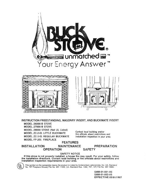
Models 26000, 27000 & 28000 - Buck Stove
Models 26000, 27000 & 28000 - Buck Stove
Models 26000, 27000 & 28000 - Buck Stove

You also want an ePaper? Increase the reach of your titles
YUMPU automatically turns print PDFs into web optimized ePapers that Google loves.
SECTION II<br />
TABLE OF CONTENTS<br />
INTRODUCTION Inside Cover<br />
BUCK STOVE FEATURES 2<br />
SECTION I MASONRY INSERT INSTALLATION 4<br />
SECTION III<br />
SECTION IV<br />
SECTION V<br />
SECTIION VI<br />
MINIMUM CLEARANCES 5<br />
REQUIRED FIREPLACE DIMENSIONS 6<br />
TOOLS FOR INSTALLATION 6<br />
INSTALLATION PREPARATION 7<br />
POSITIONING THE BUCK STOVE 7<br />
MOUNTING THE TRIM PANELS 7<br />
SEALING THE TRIM PANELS 11<br />
FINAL STEP 11<br />
FINAL CHECK , , 12<br />
FREE·STANDING INSTALLATION 13<br />
MINIMUM CLEARANCES 14<br />
TOOLS FOR INSTALLATION 23<br />
INSTALLATION PREPARATION !' , 23<br />
DETERMINING THE CHIMNEY LOCATION 24<br />
FINAL CHECK 25<br />
BUCKMATE INSERT INSTALLATION 28<br />
PARTS REQUIREMENTS 30<br />
PREPARATION AND CONSTRUCTION , 32<br />
ZC·2·01/<strong>26000</strong>·B LITTLE INSTRUCTIONS 34<br />
ZC-3-01/<strong>27000</strong>-B REGULAR AND ZC-3·01lFP-201 INSTRUCTIONS 38<br />
ELECTRICAL INSTALLATION 44<br />
FINISHING , , ..45<br />
STACK INSTALLATION 46<br />
Fp·201 OPERATION AND INSTALLATION OF GAS LOGS 48<br />
FP-201 REMOVAU<strong>27000</strong>-B STOVE INSTALLATION .49<br />
SAFETY 51<br />
CHIMNEy 50<br />
WOOD STOVE SAFETY , 52<br />
SAFETY PRECAUTIONS 52<br />
OPERATION 53<br />
BUILDING A FIRE 54<br />
GUIDE TO THE BURNING QUALITIES OF WOOD 55<br />
COAL BURNING 56<br />
HELPFUL HINTS 57<br />
MANUFACTURER'S SUGGESTED PREVENTIVE MAINTENANCE 58<br />
STOVE 59<br />
CLEANING THE STOVE 59'<br />
GLASS DOORS 59<br />
CREOSOTE-Formation and Need for Removal 60<br />
WARRANTY Back Cover<br />
Page 1
The BUCK STOVE <strong>Models</strong> <strong>26000</strong>·B, <strong>27000</strong>·B, and <strong>28000</strong> are safe and efficient heating systems<br />
which utilize either wood or Bituminous coal as fuel.<br />
The installation and operating instructions found in this manual have been developed through<br />
extensive laboratory testing and in the field experience. The procedures outlined MUST be<br />
followed exactly to ensure a safe and operational installation as well as to validate your war·<br />
ranty.<br />
Throughout the manual you will see this symbolAThiS indicates areas of importance regarding<br />
safety. Please make a special note of these areas. Read these instructions carefully<br />
before installing your BUCK STOVE and keep them with your important papers for future<br />
reference.<br />
FIGURE 1<br />
PHYSICAL FEATURES<br />
INSTALL AND USE ONLY IN ACCORDANCE WITH THE MANUFAC·<br />
TURER'S INSTALLATION AND OPERATING INSTRUCTIONS. DO NOT<br />
CONNECT THIS UNIT TO A CHIMNEY FLUE SERVING ANOTHER<br />
APPLIANCE.<br />
Page 2
BUCK STOVE FEATURES<br />
Before attempting to install or operate your BUCK STOVE, It is a good idea to familiarize<br />
yourself with the features and operating controls of the stove. (Figure 1)<br />
OPERATING CONTROLS<br />
1. DAMPER: The damper contrails located In the center of the stove, just under t he stove top.<br />
Ilis operated by lifting up on the control handle, and then pushing or pulling the handle. When<br />
the handle is lowered, the control locks Into position. The damper Is fUlly open when the con·<br />
trol is pushed if" and fully closed when the handle is pulled oul. The damper must be opened<br />
before the doors are opened.<br />
2. DOOR HANDLES: The door handles on the BUCK STOVE are air cooled and shielded. The<br />
handle on the right hand door latches the doors shut, while the left hand handle is fixed. To<br />
open the doors, rotate the right handle up, or counter clockwise one quarter turn, and pull the<br />
doors open. The doors are closed and locked by reversing the procedure.<br />
3. BLOWER CONTROL: The blower control switch is located on the lower right side of the<br />
stove front. This switch controls the functioning of the builtin fan. In the "MANUAL" position,<br />
the blower operates continuously; in the"AUTOMATIC" position, the blower is controlled by<br />
an internal thermostat in the stove which reacts to the temperature of the air between the<br />
stove walls. The speed of the blower is then dependent primarily on the size of the fire in the<br />
firebox.<br />
A CAUTIONI DO NOT unplug the blower during stove operation!<br />
4. DRAFT CONTROLS: The primary air draft controls are located on the lower portion of the<br />
doors. They are operated by sliding the controls to uncover more or less of the draft air inlets.<br />
A knob is provided which is used to operate the control and also serves a locking function. The<br />
control is locked into position by screwing it in until it is snug.<br />
5. UPPER WARM AIR OUTLET: Provides heat extraction from the top surface of the stove.<br />
6. UPPER TRIM PANEL: Seals the fireplace against soot and ash, and prevents warm room<br />
air from escaping up the chimney on masonry insert.<br />
7. DECORATIVE BRASS KNOBS: Adds an attractive accent to the stove's appearance.<br />
8. GOLD TRIM: Same as brass knobs for masonry inserl.<br />
9. SIDE TRIM PANEL (2): Same as top trim panel for masonry insert.<br />
10. AIR INLET: Allows cooler room air to be circulated through the blower and back into the<br />
warm air chamber of the stove.<br />
11. SIDE WARM AIR OUTLET (2): Extracts heat from the sides of the firebox.<br />
12. STAND: Elevates free standing stove for safety and a beautiful appearance.<br />
13. DOORS: Provides an "airtight" feature. The doors allow a much higher burning efficiency<br />
than can be obtained with an open firebox.<br />
14. LOWER WARM AIR VENT: Extracts heat from the bottom of the firebox. It is a primary part<br />
of the patented air flow pattern of the BUCK STOVE.<br />
15. HEARTH PLATE: Offers protection from spilling ashes and cinders on the fireplace hearth.<br />
It also separates the warm air outlet from the primary draft air.<br />
16. SMOKE HOOD OR VISOR: Helps trap any smoke which escapes when the doors are opened<br />
too rapidly. After !tle doors are opened. the natural draft of the stove will pull the smoke<br />
back inside.<br />
17. POWER CORD: Provides electrical power 10 operate the blower.<br />
18. STACK: Chimney connector for free standing stove.<br />
Page 3
SECTION I: INSTALLATION<br />
A ALL DIMENSIONS SHOWN<br />
ARE MINIMUM ALLOWED<br />
FOR WARRANTY<br />
FIGURE 1 INSTALLED MINIMUM CLEARANCES<br />
Minimum Clearances:<br />
The BUCK STOVE fireplace <strong>Models</strong> <strong>26000</strong>-B, <strong>27000</strong>-8 and <strong>28000</strong> are intended for installation<br />
in accordance with the standard for chimneys, fireplaces, vents. and solid-fuel burning appliances,<br />
NFPA-211 code. BUCK STOVES are NOT intended for use with a factory-built metal fireplace.<br />
See Section III for <strong>Buck</strong> <strong>Stove</strong>/<strong>Buck</strong>Mate Installation Instructions. The applicable parts of this<br />
code are:<br />
1. The chimney must be of masonry construction with an open cross-sectional area of at least<br />
50 square inches (7-1/4" x 7-114" square or 8" round.)<br />
2. The hearth must be of masonry construction and must extend a minimum of 16" in front of<br />
the fireplace opening and a minimum of 8" to either side of the fireplace opening.<br />
3. There must be a minimum of 8" between the side of the masonry fireplace opening and any<br />
combustible materials, or 16" between the BUCK STOVE firebox opening and any combustible<br />
materials. If there is not 16" from the front of the BUCK STOVE firebox opening and the front<br />
of the masonry hearth, a floor protector must be used in front of the hearth to protect combustible<br />
materials. The floor protector is to be of non-combustible. inorganic material equal to 3/8"<br />
thick millboard having a thermal conductivity of K=0.84 BTU/PHoF inches and must measure<br />
38" wide. The minimum clearances for the fireplace model are shown in Figure 1.<br />
4. If your fireplace has wood trim above it, or a wood mantel. it must be located so there is at<br />
least 20" between tile top of the BUCK STOVE and any part of the trim or mantel including<br />
supports. This can be reduced to 18" (See Figure 2). If a modified trim kit is used (examples<br />
shown in Figure 8, Page 9 and Bending Modification Tips for Modified Trim Kit, Page 10.)<br />
Page 5
INSTALLATION PREPARATION<br />
Fireplace<br />
1. Locate furniture and other materials away from the front of the fireplace to allow free<br />
access to the fireplace.<br />
2. Cover the hearth and adjacent floor areas with the drop cloths to protect from soiling<br />
or marring the surfaces.<br />
3. Remove the existing fireplace damper plate.<br />
4. Thoroughly clean the fireplace of ashes and soot.<br />
5. Check the chimney and smoke chamber for excessive bUildups of creosote or soot.<br />
Also, check fOf, obstructions, such as bird nest. If the chimney is excessively dirty,<br />
clean it, or have someone clean it professionally BEFORE installing or using the<br />
BUCK STOVE.<br />
<strong>Stove</strong> Preparation<br />
1. Remove the protective plastic wrapping from the stove.<br />
2. Inspect the stove for any obvious physical damage.<br />
3. Plug the power cord into a 115 VAC outlet to test the motor and fan. Place the blower<br />
control in the "MANUAL" position to test.<br />
4. Check the primary air draft controls to ensure that they slide freely and will lock<br />
into position when the control knobs are tightened.<br />
5. Check the operation of the damper control to ensure that it will open and close<br />
properly.<br />
6. Open and remove the doors and firedogs from the stove to facilitate installation.<br />
FIGURE 3 STOVE POSITIONING<br />
Cut and Remove from<br />
8ack Flange only.<br />
FIGURE 4 PREPARING GOLD TRIM<br />
POSITIONING THE BUCK STOVE<br />
When positioning the stove, the following conditions<br />
MUST be metl (See Figure 3)<br />
1. The front of the damper opening must be<br />
positioned BEHIND the rear edge of the lintel<br />
to ensure proper draft. (See Figure 3)<br />
2. The vertical plane of the fireplace front must<br />
fall BEHIND the side cold air vent on top of<br />
the stove. (In other words. it is possible to have<br />
the stove too far in as well as not far enough!)<br />
3. Center the stove in the fireplace opening.<br />
MOUNTING THE TRIM PANELS<br />
After the BUCK STOVE is positioned. as<br />
shown in Figure 3, mark the mounting position<br />
of the trim panels as follows:<br />
1. Set the top (long) trim panel in place on top<br />
of the stove. The panel should be flat against<br />
the outside face of the fireplace, and standing<br />
vertically. Mark along the lower edge of the<br />
trim panel with a pencil to make a reference<br />
line for mounting.<br />
2. Set the side trim panels in place, again flat<br />
against the face of the fireplace. Mark down<br />
the inside edge of the trim panel to make a<br />
vertical reference line.<br />
3. Slide the BUCK STOVE out of the fireplace<br />
far enough to work behind the trim panel referrenee<br />
lines.<br />
Page 7
7. Set the top trim panel In place and mount the same as the side panels.<br />
8. Slide the BUCK STOVE back Into the fireplace. Check to be sure that the trim panels are pro·<br />
perly positioned and lie flat against the front of the fireplace. If one or more of the panels is<br />
out of position, slide the stove out and reset by loosening the mounting screws and reposi·<br />
tloning in the slot. (See Figure 7)<br />
FIGURE 7<br />
CHECKING TRIM<br />
PANEL ADJUSTMENT<br />
MINIMUM CLEARANCE FOR BUCK STOVE<br />
FIREPLACE INSERTS MODIFIED TRIM KIT.<br />
FIGURE 8 INSTALLED MINIMUM CLEARANCES<br />
Figure 8 shows a <strong>Buck</strong> <strong>Stove</strong> Fireplace Insert with a modified trim kit, installed in a masonry<br />
fireplace showing minimum clearances for Georgian or Colonial type wood trim, on a masonry<br />
fireplace. If wood trim is desired around the fireplace front, modify the trim kit as shown in the<br />
bending modification tip on the following page. With modification on the stove trim kit, there<br />
must be a minimum of 6" from the cold air intake to side wood trim, and 8 12" from stove top to<br />
top wood trim. Wood trim should not exceed J!.I" thick.<br />
Page 9
SEALING THE TRIM PANELS<br />
It is necessary to seal trim panels against the<br />
stove and against the fireplace front. This will<br />
prevent the loss of warm room air up the<br />
chimney.<br />
1. (See Figure 9) Using the caulking gun and<br />
a cartridge of RTV silicone, run a bead of<br />
silicone all the way around the inside of the<br />
trim panels next to the stove.<br />
2. (See Figure 10) Attach 1 1/2" x 2" strip insulation<br />
around the back edge of the trim<br />
panels. Set the strip back 1" from the edge.<br />
NOTE: On rock face fireplaces, it may be<br />
necessary to add additional pieces of<br />
fiberglass to fill large or deep mortar joints.<br />
FINAL STEP<br />
1. Slide the stove back into the fireplace. Be<br />
sure the trim panels all tit snugly against the<br />
face of the fireplace. NOTE: Be sure the top<br />
edge of the trim panel runs true with the<br />
mortar joints on a brick fireplace. It it does not,<br />
one side of the stove can be shimmed from<br />
the bottom with metal to give a "square"<br />
appearance.<br />
2. Place a flashlight up through the damper<br />
and onto the top of the stove. Visually check<br />
all the way around the trim panels for evidence<br />
of light seepage. Any seepage should be<br />
blocked with the use of additional fiberglass<br />
and RTV silicone until a tight seal is achieved.<br />
(See Figure 10)<br />
Page 11<br />
FIGURE9<br />
FIGURE 10<br />
Standard Caulking Gun<br />
SEALING TRIM PANELS<br />
Insulafion Strip<br />
ATTACHING<br />
INSULATING STRIPS
==:Jc=::Jc=J l -)c=:Jc==Jc=::Jc=J<br />
1......-.-"-"----'-"-----'"'----»---- .c=Jr==J r===r<br />
FIGURE 11<br />
FINISHED VIEW<br />
3. Install the firedogs (or coal grate, refter to Page 56), and replace the doors.<br />
Note: Model <strong>28000</strong> is standard with bottom refractory only. Rear and side refractory can<br />
be purchased separately and must be used when burning coal.<br />
FINAL CHECK<br />
1. Recheck the specified clearances.<br />
2. Remove all foreign material from the firebox area.<br />
3. Open the primary air drafts and damper.<br />
4. Plug the power cord into a 115 VAC outlet. DO NOT route the cord under the hearth<br />
plate or in front of the stove to the opposite side.<br />
5. Place a crumpled piece of newspaper in the stove. Light it and close the doors. Ensure<br />
that the stove draws properly through the primary drafts. The paper should burn quickly<br />
and with a pronounced roaring sound.<br />
6. Check for smoke leaks around the doors.<br />
7. Open the doors and install the firescreen. Check for smoke esce.ping froln the front of<br />
the stove. Smoking usually indicates a defective or poorly positioned chimney. it a thorough<br />
review of the installation instructions does not reveal the problem, contact your BUCK<br />
STOVE dealer for assistance.<br />
NOTE: The BUCK STOVE is painted with a specially formulated high temperature paint<br />
that cures during the first two or three firings. You may notice a slight smoking effect and<br />
an odor of burning paint when you build the first fires. This is normal and is not a cause<br />
for alarm. In some cases, these fumes will activate a smoke alarm. Cracking a window<br />
near the stove will allow these fumes to escape. DO NOT build a large, roaring fire until<br />
this curing is complete or the stove finish may be damaged.<br />
Page 12
SECTION II<br />
FREE-STANDING INSTALLATION<br />
<strong>26000</strong>-8 <strong>27000</strong>-8 <strong>28000</strong><br />
SAFETY NOTICE<br />
If this stove is not properly Installed, a house fire may result. For your safety, follow<br />
the Installation directions. Contact local building or fire officials about restrictions<br />
and Installation Inspection requirements in your area.<br />
When a BUCK STOVE is to be installed as freestanding fireplace stove, kits<br />
No. L1 or P1 and S1 must be used.<br />
Page 13
<strong>27000</strong>·B BUCK STOVE<br />
A. CORNER INSTALLATIONS<br />
1. Using 3 1 /2" masonry without ventilated air space.<br />
Wall Protector Combustible Wall<br />
1'----'1--'--'__'LLJ'<br />
10lh" 7"<br />
'f -'f'"<br />
TOP VIEW<br />
" Floor<br />
Protector<br />
2. Using 3V2" masonry with 1" ventilated air space.<br />
," Air<br />
Space<br />
Wall Protector<br />
TOP VIEW<br />
Combustible Wall<br />
" Floor<br />
Protector<br />
1" Air Space ,,-''''<br />
Page 18<br />
Skip every other brick top<br />
& bottom to allow lor air<br />
flow behind masonry<br />
l 4'"<br />
Finished Floor<br />
line<br />
FRONT VIEW<br />
T 45"<br />
FRONT VIEW
6. Check for smoke leaks around the doors.<br />
7. Open the doors and install the firescreen. Check for smoke escaping from the front of the<br />
stove. Smoking usually indicates a defective or poorly positioned chimney. If a thorough<br />
review of the installation instructions does not reveal the problem, contact your BUCK<br />
STOVE dealer for assistance.<br />
TIPS ON FIRE BURNING<br />
ASH BED - Prolongs burn and helps the thermostat function properly.<br />
For best result, the ash bed should be equal to the top ash bar.<br />
GREEN WOOD vs. SEASONED WOOD - Green wood has a high<br />
moisture content, and therefore requires a hotter ignition temperature.<br />
Seasoned wood - cut at least one year before use - allows for a quicker,<br />
prolonged burn and more complete combustion.<br />
SPLIT WOOD vs. ROUND WOOD - Split wood burns easier and more<br />
rapidly, whether it's seasoned or green. If used after starting a fire,. it should<br />
be packed tightly to achieve a longer burn. Round wood burns longer, but<br />
requires more effort to start. Inserting a round piece over a bed of red coals<br />
with the damper and drafts open will help it catch fire. Round wood should<br />
be used to accomplish an all-night burn.<br />
FIRE STARTERS - Be highly selective In choosing a quick fire starter<br />
for use In your BUCK STOVE. NEVER START A STOVE FIRE WITH<br />
GASOLINE, CHARCOAL LIGHTING FLUIDS,. OR OTHER CHEMICALS<br />
WHICH COULD EXPLODE. For best results, use <strong>Buck</strong> Lite,. a safe,<br />
quick fire starter available from your <strong>Buck</strong> <strong>Stove</strong> dealer. Regular, noncolor<br />
newsprint may also be used.<br />
Page 26
HANDLE SHIELD MOUNTING<br />
The shields are required for proper installation<br />
of your <strong>Buck</strong> <strong>Stove</strong>. They are to be mounted<br />
parallel with the handle, and spaced 21f2" from<br />
the front of the boss to the front edge of the<br />
clamp. (see illustration).<br />
HANDLE SHIELD MOUNTING<br />
CATALYTIC CONVERTER RETRO-FIT<br />
UL LISTED FOR USE WITH MODELS<br />
<strong>26000</strong>, <strong>26000</strong>-8, <strong>27000</strong>, and <strong>27000</strong>-8<br />
Your BUCK STOVE has been designed to be one of the safest, most efficient and economical<br />
woodstoves in the world. Now, these qualities can be further enhanced with the addition of<br />
the ARDEN INDUSTRIES "SMOKE GENIE" CATALYTIC SYSTEM, available at your BUCK<br />
STOVE dealer.<br />
MODEL C200/R 100 for LITTLE BUCK models<br />
<strong>26000</strong> and <strong>26000</strong>-B<br />
MODEL C200/R200 for REGULAR BUCK<br />
models <strong>27000</strong> and <strong>27000</strong>-B<br />
MODEL C300/R300 for BIG BUCK<br />
MODEL <strong>28000</strong> (Not UL Listed)<br />
Page 27<br />
CUTAWAY SHOWING CONVERTER<br />
LOCATION IN UPPER REAR SECTION<br />
OF STOVE.
SECTION III<br />
BUCKMATE FIREPLACE INSTALLATION<br />
ZC-2-01/<strong>26000</strong>-B<br />
ZC-3-01/<strong>27000</strong>-B<br />
ZC-3-01/FP-201<br />
@New <strong>Buck</strong> Corporation 1985<br />
Page 28<br />
I I I<br />
f .<br />
I
A CAUTION - Refer to chimney manufacturers<br />
instructions for assembly and<br />
disassembly of chimney parts. 8e sure<br />
to follow chimney instructions for proper<br />
clearances to combustibles and proper<br />
air spacing required.<br />
Cold Air Return--+-tf<br />
On <strong>Stove</strong><br />
A CAUTION: Vented Roof Flashings are<br />
required with certain chimney installations.<br />
8e sure to use exact roof flashing<br />
as indicated on page 30 and 31.<br />
•..•.__•. Chimney Cap<br />
Roof Flashing<br />
Fire Slop Radiation Shield<br />
--- Zero Clearance Cabinet·Model ZC·2·01. ZC·3·01<br />
Page 29<br />
Slack/Damper Assembly·Provided with <strong>Buck</strong>mate<br />
<strong>Buck</strong> Slove Fireplace· Model <strong>26000</strong>-B. 270oo-B.<br />
or FP·201 Fireplace<br />
Hot Air Grills<br />
-- Fireplace Trim Panets-<br />
Provided with ZC·2·01. ZC·3·01
LISTED BUCK STOVE PARTS<br />
ZC-2-01<br />
<strong>26000</strong>-B<br />
ZC-3-01<br />
<strong>27000</strong>-B<br />
FP-201<br />
ZC-182<br />
ZC-183<br />
PARTS REQUIREMENTS<br />
BUCKMATE Zero Clearance Cabinet Assembly for <strong>26000</strong>-B <strong>Stove</strong><br />
Little <strong>Buck</strong> <strong>Stove</strong><br />
BUCKMATE Zero Clearance Cabinet Assembly for <strong>27000</strong>-8 <strong>Stove</strong><br />
and FP-201 Fireplace<br />
Regular <strong>Buck</strong> <strong>Stove</strong><br />
Fireplace<br />
Flashing (Use on OCR installations using Simpson-Dura-Vent pipe)<br />
Flat Roof Flashing (use on OCR installations using Simpson Dura-Vent pipe)<br />
LISTED DURA-VENT CHIMNEY PARTS<br />
DCR-P<br />
OCR-FRS<br />
DCR-SC<br />
DCR-C<br />
8" Triple Wall Pipe Sections: 9", 12",24", 36".<br />
8" Firestop Radiation Shield<br />
8" Storm Collar<br />
8" Chimney Cap<br />
OPTIONAL DURA-VENT CHIMNEY PARTS<br />
DCR·IS 8" Insulation Shield<br />
OCR-WS Wall Strap<br />
OCR-RSA Extended Roof Bracket<br />
OCR·E 150 or 300 Elbows (2 Maximum)<br />
OCR·ES Elbow Strap<br />
SOp·p<br />
SOP-SS<br />
SOP-FRS<br />
SDP-SC<br />
SOP-C<br />
SOp·F<br />
2P8<br />
FST8<br />
RRJS8<br />
SC6810<br />
AS8<br />
2PSS8<br />
AA8<br />
SFRC8<br />
SFSC8<br />
RF8<br />
2E8<br />
OPTIONAL 21000 DURA-PLUS DURA-VENT CHIMNEY PARTS<br />
8" Triple Wall insulated pipe SOP-TF 8" Roof Flashing<br />
sections 9", 12", 24", 36' SOP-IS 8" Insulation Shield<br />
8" Starter section<br />
8" Firestop Radiation Shield<br />
8" Storm Collar<br />
8" Chimney Cap<br />
SDP-WS<br />
SOp.ES<br />
SOp·E<br />
8" Wall Strap<br />
8" Extended Roof Bracket<br />
8" 15° or 30° Elbows (2 max.)<br />
8" Flat Roof Flashing SOp·ES 8" Elbow Strap<br />
OPTIONAL 2100° STANDEX SUPERFLUE MODEL "S" CHIMNEY<br />
8" Double Wall Pipe Sections: 12", 18",24",36",48",60"<br />
8" Firestop Thimble<br />
8" Roof Joist Shields<br />
8" Storm Collar<br />
8" Attic Insulation Shield<br />
8" Chimney Support System<br />
8" Chimney Support Strap<br />
8" Chimney Cap<br />
8" Chimney Cap<br />
8" Flashings: 1/12 to 6112, 7/12 to 12/12, 12/12 ro 21/12, flat<br />
8" Elbows: 150 or 30° (2 maximum)<br />
Note: Exterior casing may be stainless or galvanized.<br />
Page 30
A8<br />
AFSA8<br />
ASC8<br />
AWB8<br />
ASB<br />
ACB8<br />
AF8<br />
AA8<br />
A1S8<br />
8TG<br />
8TGFSA<br />
8TGRSH<br />
8TGIS<br />
8TGSB<br />
8TGWB<br />
8TGA<br />
8TGF<br />
8TGC<br />
8TGSC<br />
OPTIONAL 17000 METAL-FAB "A lt CHIMNEY<br />
8" Triple Wall Pipe: 12", 18",24",36"<br />
8" Firestop Assembly<br />
8" Storm Collar<br />
8" Wall Band<br />
8" Support Band<br />
8" Chimney Cap<br />
8" Flashings: Adjustable, flat tall, 6/12 to 15/12, 16/12 to 24/12<br />
8" Elbows: 150 or 300 (2 maximum)<br />
8" Insulation Shield<br />
OPTIONAL 2100° METAL-FAB TEMP/GUARD CHIMNEY<br />
B" Insulated Pipe: 6", 12", 18",24",36"<br />
8" Flrestop<br />
8" Radiation Shield<br />
8" Insulation Shield<br />
8" Support Band<br />
8" Wall Band<br />
8" Elbows: 150 or 300 (2 maximum)<br />
8" Flashings: 0/12 to 5/12,6/12 to 15/12, 16/12 to 24/12, tall flat<br />
8" Chimney Cap<br />
8" Storm Collar<br />
OPTIONAL 2100 0 SECURITY MODEL ASHT<br />
8L 8" Insulated Pipe: 8", 12", 18",24",36"<br />
BE 8" Elbows: 15° or 300 (2 maximum)<br />
8ST 8" Roof Support<br />
8S0 8" Offset Support<br />
8BS 8" Roof Brace<br />
8BM 8" Wall Band<br />
SF 8" Flashings: Flat (F), Peak (FP), Adjustable (FA, FB, FBB)"<br />
8RSA 8-" Allie Radiation Shield<br />
8C S" Chimney Cap: Mushroom (CG), Rain (CPR), Spark Arrestor (CPE)<br />
* NOTE - Storm Collar and Roof Radiation Shields are included. with Flashing.<br />
CAUTION: Do not mix Chimey Parts as a fire may result. Use one model of chimey parts completely<br />
for a UL Listed installation.<br />
CAUTION: Read through all of these instructions carefully. Follow Chimney Manufacturer's In·<br />
stallation exactly. Failure to install the Cabinet, <strong>Stove</strong>, and Chimney as described in the instructions<br />
will void the manufacturer's warranty and may have an affect on your Homeowner's insurance<br />
and UL Listing Status. A major cause of chimney related fires is failure to maintain<br />
required clearances (air spaces) to combustible materials. It is of utmost importance that these<br />
parts be installed only in accordance with these instructions.<br />
SPECIAL FEATURE: The FP-201 Fireplace may be removed and the Model <strong>27000</strong>-B <strong>Stove</strong> may<br />
be installed in its place in the ZC·3·01 Cabinet. This is a UL Listed procedure and does not<br />
affect the listing, safety, or warranty on the recognized components.<br />
Page 31
Install pipe to cabinet by pushing<br />
down over the starter section of pipe<br />
on the ZC Cabinet.<br />
NOTE: To ease installation of the<br />
lirst section of pipe to the<br />
BUCKMATE. use a pipe crimping<br />
tool and crimp the bottom of the inside<br />
chimney liner.<br />
Maintain a 2 Inch<br />
minimum clearance<br />
Page 42<br />
Install pipe to cabinet by pushing<br />
down over the starter section of<br />
pipe on the ZC Cabinet.<br />
Attach sheet metal<br />
clips (2 ea.) to pipe and<br />
cabinet top to assure<br />
stability.<br />
'. A WARNtNG: Do not pack reo<br />
qulred air spaces on top of<br />
cabinet or around pipe starter<br />
section with Insulation or other<br />
materials.
INSTALLING FIRESTOP RADIATION SHIELD: Nail the Flrestop Radiation Shield to the bottom<br />
of the framed ceiling opening using at least two a-penny nails per side.<br />
Chimney Installation Information<br />
ROOF CLEARANCE<br />
Frame a square openingin<br />
roof maintaining the<br />
qulred 2" clearance to c0;:'<br />
/<br />
bustlble materials between<br />
the chimney and the framed<br />
,<br />
ROOF<br />
rr=<br />
opening<br />
material.<br />
and roof Ing<br />
AntC<br />
INSULATiON SHIELD<br />
FIRESTOP RADIATI ON<br />
SHIELD<br />
Provides proper clearanee.<br />
/<br />
2" clearance does not<br />
apply.<br />
-<br />
/ .......<br />
een<br />
wall --_.. ". Clearance bet w<br />
chimney and enclosing<br />
/ -<br />
- 2",<br />
r------l --<br />
v<br />
CEILIN G<br />
ROOM<br />
8" Chimney fits between standard 16" OC joists.<br />
Page 43
FINISHING<br />
Finishing can now be completed using the desired material In accordance with local building<br />
and fire codes.<br />
CAUTION: Do not cover any opening on the BUCKMATE; heat must be allowed to escape from<br />
the openings designed Into the unit. A grilled trim panel Is provided with the trim package to<br />
cover this area. Also, the grilled opening at the bottom front of the BUCKMATE cannot be<br />
blocked.<br />
A hearth extension must extend to a<br />
minimum of 16" in front of the fireplace<br />
opening. The mantel must be positioned<br />
a minimum of 20" above the top of the<br />
trim kit hood.<br />
Use a non·combustible millboard having<br />
a thermal conductivity of K =0.84 BTU<br />
In./f1. 2 HoF or a listed floor protector. The<br />
miliboard or floor protector may be<br />
covered with a non-combustible material<br />
such as marble, slate, tile, etc.<br />
Optional<br />
Fire Code<br />
Shoel Rock<br />
A ALL DIMENSIONS<br />
SHOWN ARE<br />
MINIMUM ALLOWED<br />
FOR WARRANTY<br />
Page 45
INSTALLING THE BUCK STOVE<br />
(See Page 48-49 for operation of the FP-201 Fireplace and for installation of gas logs)<br />
Install unit as follows:<br />
a. Carefully reinspect chimney connections,<br />
vent outputs and cabinet air intakes after<br />
finishing is completed.<br />
b. Thoroughly clean all masonry mud and<br />
debris from cabinet and surrounding environment.<br />
c. Ensure that BUCKMATE has not been<br />
damaged during masonry process.<br />
d. Remove protective plastic wrapping from<br />
fireplace.<br />
e. Inspect motor and associated hardware<br />
for damage.<br />
f. Remove doors to facilitate installation.<br />
g. Slide the BUCK STOVE FIREPLACE into<br />
the BUCKMATE all the way to the back so<br />
that the BUCK STOVE FIREPLACE fits<br />
squarely against the back stove stop.<br />
FIGURE 7 INSTALLING STACK TO CHIMNEY<br />
h. Turn stack positioning nuts counterclockwise<br />
allowing stack to be lowered.<br />
Push downward and fit evenly until ....----------------,<br />
recessed within the stack opening (containing<br />
the damper.) Secure tightly with<br />
''T'' clamps, bolts, and nuts provided.<br />
(See Figures 7 and 8). Ensure stack mates<br />
squarely, and gasket seals completely.<br />
A CAUTION: Before installing trim<br />
panels, recheck BUCKMATE air intake<br />
and output openings for<br />
obstructions. Ensure that finishing<br />
materials have not been built over<br />
openings. This is very critical. Attach<br />
the stack by placing the stack<br />
brackets down on the lip on the Inside<br />
lower edge of the stack. Insert<br />
the bolts through the holes in the<br />
damper brackets and fasten securely<br />
with the lock washers and nuts provided.<br />
Be sure the stack sits squarely<br />
on the top of the stove with the<br />
gasket material making a good seal.<br />
(See Figure 8).<br />
FIGURE8 (MOUNTING STACK)<br />
Page 46
i. Install the trim kit attaching it to<br />
the BUCKMATE or finished<br />
framing by using 1" screws to<br />
secure the trim panels in place.<br />
j. Remove cover plate from BUCK·<br />
MATE exposing receptacle. Roll<br />
up power cord so it will fit inside<br />
of cover box. Plug in power cord<br />
in receptacle. Replace cover<br />
plate. (See Figure 9).<br />
k. <strong>Stove</strong> Doors are made of high<br />
quality cast iron which resist<br />
warpage over conventional<br />
steel doors and should never<br />
require hinge adjustment. Inside<br />
glass and draft block mounting<br />
screws should periodically be<br />
inspected for tightness. If the<br />
screw becomes loose, retighten.<br />
I. Check primary air draft control on<br />
each door.<br />
FINAL CHECK-OUT<br />
Perform final check·out as follows:<br />
FIGURE 9<br />
a<br />
""",-<br />
Sheet Metal<br />
Screws<br />
a. Remove all foreign material from stove and set firedogs in place.<br />
b. Flip blower switch to AUTOMATIC. Blower should stop. The thermostat will automatically<br />
cycle the blower on and off when a fire,is burning in the stove.<br />
c. Open primary air draft controls on doors. and open damper completely.<br />
d. Place a piece of newspaper in the stove. light it and close the doors. Ensure that the stove<br />
draws properly through the primary air intakes. The paper should burn very quickly with a<br />
pronounced roaring sound.<br />
e. Open the doors and install the fireplace screen. Make sure that no smoke escapes from the<br />
front of the stove with the doors opened. Smoking indicates a defective or poorly positioned<br />
chimney. If a thorough review of the installation requirements does not reveal the problem,<br />
contact your BUCK STOVE Dealer for assistance.<br />
OPERATING INSTRUCTIONS FP-201 FIREPLACE<br />
The FP·201 Fireplace Is designed for installation into the ZC·3·01 BUCKMATE Cabinet. These<br />
units are preassembled at the factory and do not require adjusting during installation. Use the<br />
Fireplace as you would a conventional masonry fireplace. Except:<br />
1) Use only the intergral grate provided with the unit. Do not elevate the fire.<br />
DAMPER OPERATION:<br />
Before building a fire, position the damper handle to the wide open position (up). After the fire<br />
is completely out and all embers are cold, position the damper handle to the fully closed position<br />
(down).<br />
CAUTION: When using the decorative appliance (gas logs), the fireplace damper must be<br />
set In the fully open position.<br />
Page 47
FIRE CURTAINS<br />
Do not leave the fire unattended with the fire curtains open. Heat safely by burning with the<br />
curtains closed except for start-up of the fire and reloading of wood.<br />
PRECAUTIONS:<br />
Do not overfire. If unit or chimney connector glows, you are overfiring. Keep furnishings and<br />
other combustibles far away from the appliance.<br />
INSTALLATION OF OPTIONAL DECORATIVE GAS LOGS<br />
The FP-201/ZC-3-01 is designed to house the installation of decorative gas logs in accordance<br />
with the National Fuel Gas Code, ANSI Z223-1-1980. The following steps must be taken for proper<br />
installation:<br />
1) Remove the front trim panel from the cabinet (3 vertical screws on each side).<br />
2) Remove the knock-out in the left bottom side of the outer cabinet. Remove the<br />
insulation (1" diameter) directly behind the knock-out.<br />
3) Remove the pipe cap from the pipe extending from the left bottom side of the FP-201<br />
Fireplace.<br />
4) Remove the left side refractory from the unit. Using a coal chisel and hammer, remove<br />
the knock-out in the lower side of the refractory. Replace side refractory and secure in<br />
place as previously installed.<br />
5) Install and use a gas appliance which conforms to the above code. Follow the manufacturer's<br />
installation instructions exactly for the installation and operation of the decorative<br />
gas appliance.<br />
6) Reinstall the front trim panel.<br />
INSTALLATION OF OPTIONAL OUTSIDE AIR KIT (MODEL OA-201)<br />
The major parts of the outside air kit are factory installed. You will have to complete the assembly<br />
as follows:<br />
1) Prior to framing the unit, complete the Outside Air Kit by connecting and running 4"<br />
dryer pipe from the unit to a designated outside air pick-up wall.<br />
2) Use the vent hood provided to complete installation.<br />
WARNING: Install the outside air ductlng on a plane level to or lower than the connection<br />
Joint on the cabinet. Installations with the vent hood higher than the connection may cause<br />
a chimney-effect draw and a house fire may result.<br />
INSTALLATION OF OPTIONAL GLASS DOORS (MODEL BFG-201)<br />
Installation of the optional glass doors is simple.<br />
1) Using a phillips head screw driver, simply remove the brass screws on top and sides<br />
of the brass at the fireplace opening. Remove brass trim and set aside.<br />
2) Open and inspect the glass door kit. The entire kit includes the door framing, left and<br />
right doors, and four mounting screws.<br />
3) Now, open the doors and set the door assembly into the fireplace opening with the door<br />
handles to the bottom.<br />
4) While holding the unit in place, use a 1" socket or nutdriver and secure the doors to the<br />
fireplace by screwing the self-tapping screws into the holes which previously were used<br />
to hold the brass trim in place. Door installation is now complete.<br />
CAUTION: To prevent skin burns, be sure to mount the doors with the handles to the<br />
bottom.<br />
Page 48
CHIMNEY MAINTENANCE<br />
Creosote and Soot - Formation and Need for Removal:<br />
When wood is burned slowly, it produces tar and other organic vapors,<br />
which combine with expelled moisture to form creosote. The creosote<br />
vapors condense in the relatively cool chimney flue of a slow-burning fire.<br />
As a result, creosote residue accumulates on the flue lining. When ignited,<br />
this creosote makes an extremely hot fire.<br />
Chimney Cleaning:<br />
1. Access - Chimneys must be installed so that access is provided for inspection<br />
and cleaning.<br />
2. When to Clean - The chimney should be inspected at least once every<br />
other month during the heating season to determine if creosote or soot<br />
has built up. Check spark arrestor screens every 2-4 weeks. If creosote<br />
or soot has accumulated, it should be removed to reduce the risk of chimney<br />
fire.<br />
3. How to Clean· Have your chimney cleaned by a professional chimney<br />
sweep if you have doubts about your ability to clean it, using a plastic,<br />
wood, or steel brush. Do not use a brush that will scratch the stainless<br />
steel liner of your chimney. Scrub the spark arrestor with a wire brush.<br />
To remove the Chimney Cap for cleaning, unscrew the four screws that<br />
attach the cap's support legs to the cap base. The Tee Cleanout Cap can<br />
be removed once the screws are unscrewed. Remember to replace the<br />
screws when you are through cleaning the chimney.<br />
4. Coal - To reduce corrosion in chimneys where coal is burned, clean<br />
the chimney thoroughly within 48 hours of shutting down the stove for the<br />
season. Check the chimney's lining for sulfuric acid corrosion regularly.<br />
5. No Chemical Cleaners - Do not use chemical chimney cleaners. Their<br />
use does not eliminate the need for mechanical cleaning and they may<br />
be highly corrosive.<br />
6. In Case of Fire - If a flue fire occurs, close all appliance draft openings<br />
and call your Fire Deparment. Do not use the chimney again until it is inspected<br />
for possible damage.<br />
7. Chimney Protection· Painting. To increase chimney life, coat all exterior<br />
metal parts with high temperature rust-proof paint. This is highly<br />
recommended, particularly in areas near the ocean. Wash the metal with<br />
a vinegar and water solution before painting.<br />
Page 50
SECTION IV A<br />
A SAFETY A<br />
Page 51
WOOD STOVE SAFETY<br />
Certain safety hazards are inherent in any wood stove installation. You should be aware of these<br />
so that a safe and proper installation can be made.<br />
1. FAULTY CHIMNEY: An older masonry chimney should be thoroughly checked to<br />
be sure there are no holes or weak spots which could allow sparks or hot gasses to escape.<br />
HEAT CONDUCTION: Placing combustible materials too close to a stove or chimney<br />
can be a fire hazard.<br />
By keeping these particular hazards in mind as you install and use your BUCK STOVE you<br />
can ensure a safe. reliable installation.<br />
SAFETY PRECAUTIONS<br />
For your protection. read and follow these safety precautions closely:<br />
1. Use a spark arresting shield (3/B" mesh) on top of the chimney. Check monthly as this is a<br />
code requirement in some areas.<br />
2. Use smoke detectors around the stove as well as in sleeping areas.<br />
3. Keep a fire extinguisher rated for Class "A" fires near the stove.<br />
4. Check with your insurance company to be sure your policy covers the installation and<br />
use of a wood stove.<br />
5. Creosote-Formation and Need for Removal: When wood is burned slowly. it produces<br />
tar and other organic vapors, which combine with expelled moisture to form creosote.<br />
The creosote vapors condense in the relatively cool chimney flue of a slow-burning fire. As<br />
a result, creosote residue accumulates on the flue lining. When ignited this creosote<br />
makes an extremely hot fire.<br />
The connector and/or chimney should be inspected at least every other month during the<br />
heating season to determine if a creosote buildup has occured.<br />
If creosote has accumulated, it should be removed to reduce the risk of a chimney fire.<br />
6. Locate furniture and any other combustibles away from the stove.<br />
7. Store firewood at a safe distance from the stove.<br />
8. Disposal of Ashes: Ashes should be placed in a metal container with a tight fitting lid. The<br />
closed container of ashes should be placed on a noncombustible floor or on the ground,<br />
well away from all combustible materials. pending final disposal. If the ashes are<br />
disposed of by burial in soil or otherwise locally dispersed, they should be retained in<br />
the closed container until all cinders have thoroughly cooled. Ashes can ignite up to<br />
72 hours after removal.<br />
9. Always exercise caution when using your BUCK STOVE. Be particularly careful when<br />
there are children around an operating stove.<br />
CAUTION: NEVER use gasoline, gasoline-type lantern fuel, kerosene, charcoal lighter fluid<br />
or similar liquids to start or "freshen up" a fire in the BUCK STOVE. Keep all such liquids well<br />
away from the stove when it is in use. All fluids of this type give off highly volatile fumes and<br />
can and WILL EXPLODEI Don't take a chance with the safety of your home and family.<br />
Page 52
SECTION V<br />
OPERATION<br />
Page 53
Guide To The Different Burning Qualities of Wood<br />
TYPE OF WOOD EASE OF STARTING COALING QUALITIES 6.MOUNT OF SPARKS<br />
APPLE POOR EXCELLENT FEW<br />
ASH FAIR GOOD FEW<br />
BEECH POOR GOOD FEW<br />
BIRCH GOOD EXCELLENT MODERATE<br />
CHERRY POOR EXCELLENT FEW<br />
CEDAR EXCELLENT POOR MANY<br />
ELM FAIR GOOD VERY FEW<br />
HEMLOCK GOOD LOW MANY<br />
HICKORY FAIH EXCELLENT MODERATE<br />
LOCUST POOR EXCELLENT VERY FEW<br />
MAPLE POOR EXCELLENT FEW<br />
OAK POOR EXCELLENT FEW<br />
PINE EXCELLENT POOR MODERATE<br />
The Maine Audubon Society recently charted the heat produced by a wood fire. They<br />
noted that the heat produced by a wood nre .. aries greatly with the kind of wood burned.<br />
Beech is considered the best wood for a fire. A cord of well·seasoned Beech will pro·<br />
duce as much heat as 169 gallons of fuel all. Sugar Maple and Red Oak produce as<br />
much heat as 166 gallons of fuel oil, followed by White Ash, 154; American Elm, 130;<br />
White Birch. 124; and White Pine. 94.<br />
HOW TO COOL IT IN THE SUMMER<br />
Empty and clean the firebox of all ashes at the end of the heating season, tOllch·up the exterior<br />
of the stove with an approved stove paint (spray type preferable) and you will be ready<br />
when the next heating season rolls around. You do not need to let your BUCK STOVE sit idle<br />
during the warm summer months. Your versatile BUCK STOVE will double as at cool air cir·<br />
culator during the summer. It's very simple.<br />
1. Fill four containers (plastic milk containers work very well) with water and freeze.<br />
2. Place frozen containers inside the cleaned firebox on their sides.<br />
3. Close doors and all dampers and switch the fan to the "manual" setting. This by-passes the<br />
thermostat so the fan will run continuously.<br />
Four one gallon frozen containers will provide reasonable cooling. Don't expect your stove to<br />
cool as well as It heats, but this is a nice, extra feature for your benefit.<br />
COOLING A HOT STOVE<br />
In the event that your room becomes too warm for comfort, the quickest and best way to cool<br />
your stove is to open the damper fully, open the doors, and install a firescreen. NOTE: Unplug·<br />
ging the blower will cause your stove to retain heat, making your room stay holler for a longer<br />
period. Unplugging may also damage the electrical components of the stove, so never unplug<br />
the stove during use.<br />
Page 55
Your BUCK STOVE can burn Bituminous soft type coal only (not Anthracite) with the optional<br />
BUCK STOVE'" COAL GRATE available at your <strong>Buck</strong> <strong>Stove</strong> dealer.<br />
<strong>Models</strong> available:<br />
CG·<strong>27000</strong> for all Regular <strong>Buck</strong> <strong>Models</strong>: <strong>27000</strong>·B and Big <strong>Buck</strong> Model: <strong>28000</strong>.<br />
'------L\<br />
COAL GRATE AND REFRACTORY SIDE LINING<br />
_Features include a separate stand for properly elevating grate for proper draft to fire coal.<br />
Can also be used for firedog (andirons).<br />
-Shaker for sifting ash.<br />
-Shaker arm with wood handle.<br />
- Removable basket front for ease of assembly and cleaning.<br />
Complete assembly and read operating Instructions for the BUCK STOVE before installing the<br />
BUCK STOVE Coal Grate.<br />
A CAUTION: Side Liners must be Installed In the BUCK STOVE before Installing the<br />
BUCK STOVE Coal Grate.<br />
Page 56
SECTION VI<br />
MANUFACTURER'S SUGGESTED<br />
PREVENTIVE MAINTENANCE<br />
Page 58
CHECK<br />
CHIMNEY<br />
A. The chimney should be cleaned as necessary to remove creosote, soot, leaves, birds'<br />
nests, etc. (Refer to Page 50, Creosote)<br />
B. A neglected chimney can eventually cause a draw restriction or can ignite and burn<br />
hot enough to cause damage to the chimney.<br />
C. For proper inspection the chimney should be cleaned.<br />
D. A topper or cover should be installed to prevent moisture from entering chimney, to<br />
prevent sparks and burning materials from escaping chimney, and to keep birds and foreign<br />
materials from entering.<br />
NOTE: Some areas may require an approved spark arrestor.<br />
STOVE<br />
A. The stove should be pulled from the masonry fireplace as necessary to remove soot<br />
and ashes from around the stove.<br />
B. The seal of the kit to the stove and the kit to the masonry should be checked and also<br />
resealed if there is any evidence of soot, ash, or smoke leakage.<br />
C. Check gasketing around doors for any signs of excessive wear.<br />
CLEANING THE STOVE<br />
A. The stove should not be cleaned with any type of detergent as most all detergents have<br />
an oil base and cannot be painted over.<br />
B. The stove should be lightly sanded with fine sandpaper or steel wool, then repainted<br />
or touched-up with high temperature black paint.<br />
C. If the stove is located in a moist or damp location, check thoroughly for signs of condensation<br />
during times when the stove is not in use.<br />
D. When the heating season is over, the stove can be cleaned out completely with a wire<br />
brush or cloth to eliminate ash and burned wood smell.<br />
GLASS DOORS (OPTIONAL)<br />
A. Glass doors should be handled as any other breakable glass. Heat or flames from the<br />
fire will not break the glass. However, rough handling when the glass is hot or forcing the<br />
door closed against the wood can cause breakage.<br />
B. Soot and smoke will cloud the glass panes very quickly when using soft wood such as<br />
pine. However, in time, this will burn off or may be cleaned with a good oven type cleaner.<br />
C. Check gasketing around glass for signs of deterioration.<br />
• • • • Most of the preventive maintenance procedures can be performed by your local<br />
BUCK STOVE dealer or certified BUCK STOVE installer···· .<br />
FINAL NOTES: Fill out and mail the warranty card to the address indicated. If you have<br />
any questions concerning the operation of your BUCK STOVE, contact your local dealer.<br />
He will be happy to help you.<br />
THANK YOUI We are prOUd to have you join our nation-wide family of satisfied BUCK<br />
STOVE owners.<br />
Page 59
CREOSOTE - Formation and Need for Removal<br />
When wood is burned slowly, it produces tar and other organic vapors, which combine with<br />
expelled moisture to form creosote. The creosote vapors condense In the relatively cool<br />
chimney flue of a slow·burnlng fire. As a result, creosote residue accumulates on the flue lining.<br />
When ignited this creosote makes an extremely hot fire.<br />
The chimney connector and chimney should be inspected at least once every two months.<br />
More frequent inspection and cleaning may be necessary, under certain conditions of use<br />
creosote build·up may occur rapidly.<br />
Creosote is caused by low temperatures in the chimney, which is controlled by the operator<br />
of the stove.<br />
The damper on the stove controls the speed of the air tllat goes up the chimney, and the<br />
drafts in the doors govern the volume of air entering the firebox, which, in turn controls the<br />
temperature of the fire.<br />
Many experienced wood stove operators state that having a short, 10-30 minute DAILY hot<br />
burn (accomplished by using three pieces of split, seasoned hardwood cut into chunks with a<br />
three-to-four inch diameter with the drafts and damper open) will raise the stack temperatures<br />
sufficiently to reduce excessive creosote accumulation.<br />
Installation of the Arden Industries "Smoke Genie" catalytic system into your <strong>Buck</strong> <strong>Stove</strong><br />
can eliminate up to 50-90% of the creosote produced during normal operation.<br />
THERMOSTAT<br />
After the thermostat sits dormant through an off-healing season, it may need to be<br />
operated in the manual setting a few limes at the start of a new heating season to break itself<br />
in.<br />
IMPORTANT - The following explains the significant functions of some parts in your<br />
BUCK STOVE.<br />
THERMOSTAT - The stove is equipped with three thermostatically controlled blower<br />
speeds. Under normal operation, the blower will operate on low or medium. Whenever the<br />
blower goes into high automatically, the stove has been overfired, but can be quickly cooled<br />
by opening the damper and closing the drafts.<br />
SIDE LINER - Reflects heat back into the fire for more complete combustion and even·<br />
Iy distributes the heat throughout the stove to help guard against firebox warpage.<br />
MOTOR THERMAL·OUT - The motor is designed with a thermal overload function,<br />
which shuts off themotor automatically if it becomes overheated. This keeps the motor's elec·<br />
trical system safe. The motor is not designed to run on high speed continuollsly.<br />
Page 60