Simplex 900 Instructions - Kaba Ilco
Simplex 900 Instructions - Kaba Ilco
Simplex 900 Instructions - Kaba Ilco
Create successful ePaper yourself
Turn your PDF publications into a flip-book with our unique Google optimized e-Paper software.
<strong>Kaba</strong> Access Control<br />
2941 Indiana Avenue Winston-Salem, NC 27105 USA<br />
Tel: (800) 849-8324 (336) 725-1331<br />
Fax: (800) 346-9640 (336) 725-3269<br />
www.kabaaccess.com PKG1819 0307<br />
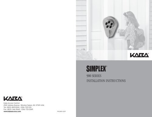
<strong>900</strong> SERIES<br />
INSTALLATION INSTRUCTIONS
Table of Contents<br />
STEP . . . . . . . . . . . . . . . . . . . . . . . . . . . . . . . . . . . . . . . . . . . . . . . . . . . . . . . . .PAGE<br />
Checklist/tools required . . . . . . . . . . . . . . . . . . . . . . . . . . . . . . . . . . . . . . . . . . . . . . . . . . . .3<br />
A Determining the lock handing . . . . . . . . . . . . . . . . . . . . . . . . . . . . . . . . . . . . . . . . . . . . . . .4<br />
B Marking the door . . . . . . . . . . . . . . . . . . . . . . . . . . . . . . . . . . . . . . . . . . . . . . . . . . . . . . . . . .4<br />
C Drilling the holes . . . . . . . . . . . . . . . . . . . . . . . . . . . . . . . . . . . . . . . . . . . . . . . . . . . . . . . . . .5<br />
D Installing the key cylinder . . . . . . . . . . . . . . . . . . . . . . . . . . . . . . . . . . . . . . . . . . . . . . . . . .5<br />
E Installing the lock . . . . . . . . . . . . . . . . . . . . . . . . . . . . . . . . . . . . . . . . . . . . . . . . . . . . . . . . . .6<br />
F Installing the strike . . . . . . . . . . . . . . . . . . . . . . . . . . . . . . . . . . . . . . . . . . . . . . . . . . . . . . . .7<br />
G Testing the lock’s operation . . . . . . . . . . . . . . . . . . . . . . . . . . . . . . . . . . . . . . . . . . . . . . . . .9<br />
H Changing the combination . . . . . . . . . . . . . . . . . . . . . . . . . . . . . . . . . . . . . . . . . . . . . . . . . .9<br />
I Disassembling the lock/reversing the latch . . . . . . . . . . . . . . . . . . . . . . . . . . . . . . . . . . .11<br />
J <strong>Instructions</strong> for resetting unknown combination . . . . . . . . . . . . . . . . . . . . . . . . . . . . . .12<br />
K Lever handle/panic hardware kits assembly instructions . . . . . . . . . . . . . . . . . . . . . . .13<br />
L Troubleshooting . . . . . . . . . . . . . . . . . . . . . . . . . . . . . . . . . . . . . . . . . . . . . . . . . . . . . . . . . .14<br />
Warranty card . . . . . . . . . . . . . . . . . . . . . . . . . . . . . . . . . . . . . . . . . . . . . . . .center of book<br />
Template . . . . . . . . . . . . . . . . . . . . . . . . . . . . . . . . . . . . . . . . . . . . . . . . . . . . . .back of book<br />
Warning: The combination of this lock has been factory preset: II and IV<br />
depressed together, then III. For your security, the combination must be<br />
changed at time of installation.<br />
Please read and follow all<br />
directions carefully<br />
Since correct installation is critical,<br />
carefully check windows, frame,<br />
door, etc. to make sure that the<br />
recommended procedures will not<br />
cause any damage.<br />
KABA is not responsible for any<br />
damage caused by installation.<br />
For your records<br />
Model No.:<br />
Date Purchased:<br />
Dealer:<br />
Name:<br />
Telephone:<br />
For technical assistance please call<br />
1-800-849-TECH (8324) or 336-725-1331<br />
Checklist Each <strong>900</strong> Series lock includes:<br />
❑ A) Lock housing assembly<br />
❑ B) Face plate with outside knob<br />
❑ C) Strike plate (for outswing doors)<br />
❑ D) Strike box (for inswing doors)<br />
❑ E) Screw/accessory pack:<br />
a) holding bracket<br />
b) three 1 1 ⁄2" (38 mm) screws<br />
for the lock housing<br />
c) two 1 ⁄2" (13 mm) screws for<br />
the holding bracket<br />
d) Allen wrench<br />
e) three 1" (25 mm) screws for<br />
the strike box<br />
❑ F) Key override assembly Only included with<br />
key override models (906, 910, 935, 938).<br />
f) cup flange<br />
g) key cylinder with key<br />
h) two screws and washers<br />
i) thin metal spacer<br />
j) trim ring<br />
k) Spacer ring<br />
❑ G) Surface Mount strike for steel door frames<br />
(purchased separately)<br />
Tools required:<br />
❑ Electric drill (variable speed recommended)<br />
❑ Awl or center punch<br />
❑ 1 5 ⁄8" (41 mm) Hole saw with pilot drill<br />
❑ 7 ⁄8" (22 mm) Hole saw with pilot drill<br />
❑ 1 ⁄8" (3 mm) Drill bit<br />
❑ Hammer<br />
❑ Phillips head screwdriver<br />
❑ Small flat blade screwdriver<br />
❑ 1" (25 mm) Chisel<br />
❑ Pliers (2) for key override models only<br />
2 3<br />
e<br />
B<br />
C<br />
f<br />
E<br />
F<br />
a<br />
j<br />
h<br />
i<br />
g<br />
G<br />
c<br />
d<br />
A<br />
D<br />
h<br />
b<br />
k
A. DETERMINING THE LOCK HANDING<br />
Many of the installation instructions refer to the<br />
handing of your door, so you should determine the<br />
hand before starting the installation.<br />
The hand of the door is determined with the door<br />
in the closed position, from the exterior (pushbut-<br />
RH LH<br />
ton side) of the door (See Figure 1-1 and 1-2). 1-1<br />
RH - Right hand door. Door opens inward (push).<br />
Hinged on the right side.<br />
LH - Left hand door. Door opens inward (push).<br />
Hinged on the left side.<br />
RHRB - Right hand reverse bevel door. Door opens<br />
RHRB LHRB<br />
outward (pull). Hinged on the right side.<br />
1-2<br />
LHRB - Left hand reverse bevel door. Door opens outward (pull). Hinged on the<br />
left side.<br />
Once you have determined the handing of your<br />
door, you should determine the distance above your existing primary lockset<br />
where the auxiliary lock will be mounted – 8" to 10" (203 mm to 254 mm) is<br />
recommended.<br />
B. MARKING THE DOOR<br />
The door must be closed.<br />
B-1 Remove the template from the center of this<br />
booklet.<br />
B-2 Fold the template on the solid line for an<br />
inswing door, if you are not using a riser plate.<br />
Fold the template on the dashed line for an<br />
outswing door, or if you are using a riser plate<br />
A<br />
with an inswing door.<br />
B-3 Tape the template securely to the inside surface<br />
of the door so that the indicated fold is 2-1<br />
aligned with the edge of the door or door stop,<br />
if one is present. Figure 2-1 shows the inside<br />
of a left hand door; Figure 2-2 shows the<br />
inside of a right hand door.<br />
B-4 Use a center punch (or similar marking tool)<br />
to make the marks for drilling the five holes<br />
precisely at the points indicated on the<br />
template; there is a sixth hole (A) for key<br />
override models.<br />
B-5 Remove the template.<br />
2-2<br />
4<br />
A<br />
C. DRILLING THE HOLES<br />
CAUTION: Positioning and drilling must be done straight to avoid excessive<br />
force being exerted on the lock which may result in the premature wearing of<br />
its mechanical parts.<br />
NOTE: The latch is reversible on spring latch models 917, 919, 935, 938, and<br />
929. Refer to the instructions in Section I, “Disassembling the Lock.”<br />
Use a variable speed drill to prevent splintering the door or breaking the drill<br />
bit. Begin drilling at a slow speed and increase the speed gradually until the tip<br />
of the pilot bit emerges through the other side of the door. Repeat this procedure<br />
from the opposite side of the door to complete the 7 ⁄8" (22 mm) and 1 5 ⁄8"<br />
(41 mm) holes. Use a 1 ⁄8" (3 mm) drill bit to make pilot holes for the three<br />
mounting screws.<br />
C-1 Drill the holes according to the template<br />
(See Figure 3-1; right hand door shown).<br />
All models require 5 holes:<br />
(A) one 7 ⁄8" (22 mm) hole<br />
(B) one 1 5 ⁄8" (41 mm) hole<br />
(C) three 1 ⁄8" (3 mm) holes for the mounting<br />
screws. Drill approximately 1 ⁄2" (13 mm)<br />
deep.<br />
Key override models require one additional hole for the key cylinder:<br />
(D) one 7 B<br />
1<br />
⁄8" (22 mm) hole.<br />
5 A<br />
7 ⁄8" (22 mm)<br />
C<br />
1 ⁄8" (3 mm)<br />
⁄8" (41 mm)<br />
3-1<br />
D. INSTALLING THE KEY<br />
CYLINDER<br />
Shortening the cylinder tailpiece:<br />
D-1 Determine the lock and riser plate you are<br />
using then select the break line from the<br />
table at right.<br />
Lock A = Models 902, 906, 917, 935 for doors 1<br />
3 1 ⁄8" (35 mm) to 1 ⁄2" (38 mm) thick<br />
Lock B = Models 904, 910, 919, 938, 929 for<br />
doors 1 3 ⁄4" (44 mm) to 2 1 ⁄8" (54 mm) thick<br />
D-2 Hold the tailpiece firmly with a pair of pliers<br />
(A) on the cylinder end of the tailpiece, just<br />
beside the desired break line (See Figures<br />
4-1 and 4-2).<br />
D-3 With a second pair of pliers (B), grip the tailpiece<br />
at the other side of the line and bend up<br />
and down until it breaks.<br />
C<br />
1 ⁄8" (3 mm)<br />
D<br />
7 ⁄8"<br />
(22 mm)<br />
C<br />
1 ⁄8" (3 mm)<br />
Lock Riser Plate Break Line<br />
A --- 1<br />
B ---- 1<br />
A 1/4" (6 mm) side 2<br />
A 3/8" (10 mm) side 2<br />
B 1/4" (6 mm) side 2<br />
B 3/8" (10 mm) side 3<br />
4-1<br />
B<br />
4-2<br />
A<br />
5
Installing the key cylinder:<br />
D-4 (See Figure 4-3). Insert the cup flange (A) into<br />
the 7 ⁄8" (22 mm) hole on the inside of the door<br />
so that the hole in the flange of the cup (D) is<br />
over the 1 ⁄8" (3 mm) screw hole in the door.<br />
D-5 Place the trim ring (B) onto the key cylinder<br />
shank, followed by the spacer (E) if needed.<br />
D-6 Insert the key cylinder (C) through the 7 ⁄8" (22<br />
mm) hole from the outside of the door. Make<br />
sure that the two holes in the cylinder are positioned<br />
at the top of the hole.<br />
D-7 Secure the cup flange to the door with two<br />
screws (item h from checklist); the screws attach<br />
both the cup flange and the key cylinder to the door.<br />
D-8 Place the thin metal plate over the key cylinder tailpiece and cup flange<br />
(on the inside of the door) so that the large hole fits over the large hole of<br />
the cup and the smaller hole fits over the 1 A<br />
D<br />
C B<br />
E<br />
4-3<br />
4-4<br />
⁄8" (3 mm) screw hole in the<br />
door (See Figure 4-4).<br />
E. INSTALLING THE LOCK<br />
E-1 From the inside of the door, slide the lock<br />
housing into the holes in the door (See<br />
Figure 5-1). Make sure the lock housing<br />
sits flush to the door.<br />
NOTE: The inside surfaces of some hollow metal<br />
doors are not even with the surfaces of their<br />
frames. An adjustable riser plate (Part #74468)<br />
is available to raise the lock housing 1 ⁄4" (6 mm)<br />
or 3 ⁄8" (10 mm) (See Figure 5-2).<br />
E-2 Attach the lock housing to the door with the<br />
three 1 1 ⁄2" (38 mm) mounting screws (item b on<br />
checklist) (See Figure 5-3).<br />
E-3 Place the holding bracket (A) with the slotted<br />
legs engaging the aligning pin (B) on the barrel<br />
assembly (C). Ensure that the large radius of<br />
the holding bracket is centered around the<br />
radius of the barrel assembly (See Figure 5-4).<br />
E-4 Fasten the holding bracket to the door with the<br />
two 1 ⁄2" (13 mm) screws (item c on checklist)<br />
(See Figure 5-4).<br />
6<br />
5-1<br />
5-2<br />
5-3<br />
5-4<br />
C<br />
A<br />
B<br />
E-5 Remove the three screws holding the lock<br />
housing to the door, then remove the lock<br />
housing.<br />
E-6 Slide the holding edges of the face plate (D)<br />
behind the formed-up edges of the holding<br />
bracket (A) (See Figure 5-5). Make sure that<br />
the face plate (D) is securely held on both sides.<br />
If you are installing a key override model, follow the<br />
instructions in Section D, “Installing the Key<br />
Cylinder,” then return and continue these steps.<br />
E-7 Turn the thumbturn (F) on the face plate to the<br />
vertical position and hold it in place (See<br />
Figure 5-5).<br />
E-8 Replace the lock housing making sure that the<br />
force-proof clutch (E) engages the thumbturn<br />
(F) (See Figure 5-6).<br />
If you are installing a key override model, make sure<br />
the tailpiece of the key cylinder engages the cup on<br />
the gear plate.<br />
E-9 Fasten the lock housing to the door with the<br />
three 1 1 ⁄2" (38 mm) screws (See Figure 5-7).<br />
F. INSTALLING THE STRIKE<br />
Inward Opening Door (wood frame) - mount box strike<br />
F-1 Place the strike (A) on the door frame in line with<br />
the lock (See Figure 6-1).<br />
F-2 Trace the outline of the strike on the door<br />
frame (B). Add 5 ⁄32" (4 mm) to the edge of<br />
B<br />
C<br />
the tracing (D) opposite the lock to allow for<br />
D A<br />
recessing of the strike tongue (C).<br />
F-3 Chisel out the traced area.<br />
6-1<br />
F-4 Place the strike (A) back into this cutout and trace the outline of the strike<br />
tongue.<br />
F-5 Chisel out the frame so that the strike tongue will be flush (See Figure 6-1).<br />
F-6 Place the strike back into the cutout and check that the large segment of<br />
the latch enters the strike freely.<br />
F-7 Secure the strike with three 1" (25 mm) screws (item e on checklist).<br />
5-5<br />
5-6<br />
5-7<br />
A<br />
E<br />
F<br />
D<br />
F<br />
7
Outward Opening Door (wood frame) - mount flat<br />
strike<br />
F-8 Place the strike (A) on the door frame (B) in<br />
line with the lock (See Figure 6-2).<br />
F-9 Trace the outline of the strike on the frame (B).<br />
Remove the strike.<br />
F-10 Chisel out the frame (B) so that the strike will be flush with the frame.<br />
F-11 Place the strike back into the cutout and trace the center bolt hole on the<br />
frame.<br />
F-12 Chisel this out to clear the extended bolt. The bolt must enter the strike<br />
freely.<br />
Spring Latch Models<br />
The clearance between the lock housing and the strike must not exceed 1 B<br />
A<br />
6-2<br />
⁄8" (3<br />
mm) to ensure deadlocking.<br />
Outward Opening Door (metal frame) – for doors where the strike/frame is<br />
not prepped<br />
F-13 With latch/bolt extended, gently close the<br />
door and mark the frame (B) where the<br />
latch/bolt is located.<br />
B<br />
F-14 Open the door and carefully measure and<br />
mark the door stop where the latch/bolt will<br />
6-3<br />
lock into the frame (See Figure 6-3).<br />
F-15 Remove the material you have marked.<br />
F-16 If using a spring latch model, make sure the dead locking latch can not fall<br />
into the latch/bolt hole.<br />
Inward Opening Door (metal frame)<br />
F-17 This application requires a surface mounted<br />
strike box (D) (74464) in place of the standard B<br />
strike box (riser plate kit may be needed).<br />
F-18 With latch/bolt extended, gently close the door<br />
and mark where the latch/bolt is located.<br />
D<br />
6-4<br />
F-19 Align center of latch/bolt with center line of<br />
surface mount strike latch hole. Mark 4 mounting screw holes.<br />
F-20 Drill surface strike mounting screw holes.<br />
F-21 Attach surface mount strike (D) to frame with screws supplied<br />
(See Figure 6-4).<br />
8<br />
G. TESTING THE LOCK’S<br />
OPERATION<br />
IMPORTANT: The following steps must be<br />
performed while the DOOR IS OPEN.<br />
Unlocking the Door<br />
7-1<br />
G-1 Turn the outside thumbturn to the left<br />
(counterclockwise) to the stop position and<br />
release (See Figure 7-1).<br />
G-2 Enter the preset combination (II and IV<br />
depressed together, release, then III, and<br />
release). Distinctive clicks must be felt to<br />
7-2<br />
indicate that the buttons have been fully<br />
depressed (See Figure 7-2).<br />
G-3 Turn the outside thumbturn to the right<br />
(clockwise) until it stops (See Figure 7-3);<br />
the latch/bolt should retract fully. If the latch/<br />
bolt does not retract, repeat steps G-1 to G-3.<br />
Unlocking the door using the key override<br />
7-3<br />
(models 906, 910, 935, 938)<br />
Insert the key into the cylinder, turn the key to the right (clockwise) to the stop<br />
position, and open the door.<br />
Locking the door - deadbolt models<br />
Turn the outside knob to the left (counterclockwise) to the stop position; release.<br />
Key override models 906, 910: turn the key to the left (counterclockwise) to the<br />
stop position; return the key to the pull position (vertical).<br />
The bolt extends and locks the door.<br />
NOTE: Spring latch models lock automatically when the door is closed;<br />
do not turn the outside knob or key.<br />
H. CHANGING THE COMBINATION<br />
FOR YOUR SECURITY THE COMBINATION MUST<br />
BE CHANGED WHEN THE LOCK IS INSTALLED.<br />
The door must be open.<br />
H-1 Turn the outside thumbturn to the left (counter- 8-1<br />
clockwise) (See Figure 8-1) to the stop position and release. This will clear<br />
any random entries from the mechanism. When the thumbturn is turned to<br />
the left on a deadbolt model, the bolt is automatically thrown into the<br />
locked position; therefore, it is important to keep the door open while<br />
changing the combination.<br />
9
KABA SIMPLEX ®<br />
LIMITED WARRANTY<br />
<strong>Kaba</strong> Access Control warrants this product to be free from defects in material<br />
and workmanship under normal use and service for a period of one (1) year.<br />
<strong>Kaba</strong> Access Control will repair or replace, at our discretion, locks found by<br />
<strong>Kaba</strong> Access Control analysis to be defective during this period. Our only liability,<br />
whether in tort or in contract, under this warranty is to repair or replace<br />
products that are returned to <strong>Kaba</strong> Access Control within the one (1) year warranty<br />
period.<br />
This warranty is in lieu of and not in addition to any other warranty or condition,<br />
express or implied, including without limitation merchantability, fitness for<br />
purpose or absence of latent defects.<br />
ATTENTION: This warranty does not cover problems arising out of improper<br />
installation, neglect or misuse. All warranties implied or written will be null and<br />
void if the lock is not installed properly and /or if any supplied component part<br />
is substituted with a foreign part. If the lock is used with a wall bumper, the<br />
warranty is null and void. If a doorstop is required, we recommend the use of a<br />
floor secured stop.<br />
The environment and conditions of use determine the life of finishes on <strong>Kaba</strong><br />
Access Control products. Finishes on <strong>Kaba</strong> Access Control products are subject<br />
to change due to wear and environmental corrosion. <strong>Kaba</strong> Access Control<br />
cannot be held responsible for the deterioration of finishes.<br />
Authorization to Return Goods<br />
Returned merchandise will not be accepted without prior approval. Approvals<br />
and Returned Goods Authorization Numbers (RGA Numbers) are available<br />
through our Customer Service department in Winston-Salem, NC (800) 849-<br />
8324. The serial number of a lock is required to obtain this RGA Number.<br />
The issuance of an RGA does not imply that a credit or replacement will be<br />
issued.<br />
The RGA number must be included on the address label when material<br />
is returned to the factory. All component parts including latches and strikes<br />
(even if not inoperative) must be included in the package with return. All merchandise<br />
must be returned prepaid and properly packaged to the address indicated.<br />
NO POSTAGE<br />
NECESSARY<br />
IF MAILED<br />
IN THE<br />
UNITED STATES<br />
BUSINESS REPLY MAIL<br />
WINSTON-SALEM, NC<br />
FIRST-CLASS MAIL PERMIT NO. 1563<br />
POSTAGE WILL BE PAID BY ADDRESSEE<br />
KABA ACCESS CONTROL<br />
2941 INDIANA AVENUE<br />
WINSTON-SALEM, NC 27199-3770
❏ Check here if you would like more information on <strong>Kaba</strong> Access Control locks.<br />
Lock Model Number<br />
❏ Locksmith ❏ Maintenance ❏ Other<br />
Date of Purchase<br />
Who installed your lock?<br />
Name of Dealer Purchased From<br />
What was your reason for buying this lock?<br />
Email<br />
Phone<br />
❏ Advertisement ❏ Previous Use ❏ Internet / Web ❏ Another Use<br />
❏ Locksmith ❏ Maintenance ❏ Training Class ❏ Other (please specify)<br />
State ZIP (Postal Code) Country<br />
How did you learn about <strong>Kaba</strong> Access Control Pushbutton Locks?<br />
City<br />
Address<br />
Company<br />
Position<br />
Name<br />
This lock is:<br />
❏ New Installation<br />
❏ Replacing a conventional keyed lock<br />
❏ Replacing a <strong>Kaba</strong> Mechanical Pushbutton Lock<br />
❏ Replacing a <strong>Kaba</strong> Electronic Access Control<br />
❏ Replacing a Keyless Lock other than <strong>Kaba</strong><br />
What area is being secured with this lock? (e.g. Front Door, Common Door, Exercise Room)<br />
Thank you for purchasing our product. In order to<br />
protect your investment and to enable us to better<br />
serve you in the future, please fill out this registration<br />
card and return it to <strong>Kaba</strong> Access Control, or<br />
register online at www.kabaaccess.com.<br />
❏ Commercial Building ❏ Industrial / Manufacturing ❏ Airport<br />
❏ College/University ❏ Government/Military ❏ School/Educational<br />
❏ Hospital/Healthcare ❏ Other (please specify)<br />
REGISTRATION CARD<br />
This lock will be used in what type of facility?<br />
H-2 Enter the existing combination (See Figure 8-2). On<br />
new installations, use the factory-set combination: depress<br />
II and IV simultaneously, (release), then III (release). You<br />
should feel a slight click as each button is depressed.<br />
H-3 Use the Allen wrench (item d on checklist) to remove the<br />
screw from the top of the lock housing (See Figure 8-3).<br />
H-4 After removing the screw. Insert the Allen wrench<br />
into the hole and depress the internal lockout slide;<br />
(See Figure 8-4) you should feel a slight click. Do<br />
not force.<br />
H-5 Remove the wrench.<br />
H-6 Turn the outside thumbturn to the left (counterclockwise)<br />
to the stop position and release (See<br />
Figure 8-5).<br />
H-7 Choose your new combination, (be sure to write it<br />
down) then enter the new combination (See Figure<br />
8-6) – depress buttons carefully (a slight click should<br />
be felt as each button is depressed).<br />
Note: You can use one button or all five for a<br />
combination, but each button can only be used once.<br />
You can depress two or more buttons simultaneously<br />
as a step in the combination.<br />
H-8 Turn the outside thumbturn to the right (clockwise)<br />
to the stop position and release (See Figure 8-7).<br />
The new combination is now set.<br />
H-9 Test your new combination a few times before you<br />
shut the door (See Figure 8-8).<br />
Lock and unlock the door following the instructions in<br />
Section F.<br />
If the outside thumbturn retracts the latch or bolt and<br />
you have not entered your combination, steps were<br />
done out of order and the lock is in zero code.<br />
H-10 Repeat H-1 to H-8, omitting step H-2, until the<br />
latch bolt retracts only after you enter your new<br />
combination.<br />
H-11 Replace the screw on the top of the lock housing<br />
(See Figure 8-3).<br />
NOTE: The outside thumbturn can not be forced to<br />
retract the latch/bolt because it is connected to the<br />
lock housing by a friction clutch. If the thumbturn<br />
has been forced, it can be turned back to the vertical<br />
position by hand without damaging the lock.<br />
8-2<br />
8-3<br />
8-4<br />
8-5<br />
8-6<br />
8-7<br />
8-8<br />
10
I. DISASSEMBLING THE LOCK/<br />
REVERSING THE LATCH<br />
You may need to disassemble the lock to reverse the latch on spring latch<br />
models or to clear a lost combination.<br />
I-1 Remove the lock housing (A) from the inside of<br />
the door by removing the three mounting<br />
screws (See Figure 9-1).<br />
I-2 Remove the center plate and barrel assembly<br />
(B) by removing two screws and flange washers<br />
(See Figure 9-2 and 9-3).<br />
A<br />
I-3 Remove the 2 gear plate screws (C)<br />
(See Figure 9-4).<br />
9-1<br />
Note: Skip step I-4 if reversing the latch.<br />
I-4 Remove the combination chamber (D) by<br />
removing one screw at each end of the<br />
B<br />
chamber (See Figure 9-5).<br />
Reversing the Latch<br />
I-5 Depress the latch and hold it.<br />
9-2<br />
B<br />
I-6 Use the tip of a screwdriver to gently lift the<br />
gear plate by the exposed edge so you can<br />
grasp it with your fingertips.<br />
I-7 (See Figure 9-4). Remove the gear plate (C)<br />
and place it aside. Note that the activating arm<br />
(E) is attached to the gear plate and will rise<br />
9-3<br />
with the gear plate.<br />
I-8 Release the latch slowly. Pull it out, reverse it,<br />
C<br />
and reinsert it.<br />
I-9 Depress the latch and hold it.<br />
I-10 (See Figure 9-4) Reattach the gear plate (C).<br />
F<br />
9-4<br />
E<br />
Make sure that the stud on the end of the activating<br />
arm (E) is resting in the curved slot on<br />
the throw cam (F).<br />
I-11 When the gear plate is flush with the back surface<br />
of the lock, release the latch and replace<br />
D<br />
the screws attaching the gear plate.<br />
I-12 Reassemble the center plate and barrel<br />
assembly (See Figure 9-2).<br />
9-5<br />
11<br />
J. INSTRUCTIONS FOR RESETTING UNKNOWN<br />
COMBINATIONS<br />
Follow the instructions in Section I, “Disassembling the lock.” Remove the lock<br />
from the door and disassemble it as instructed (See Figure I-1 to I-4).<br />
To remove the 3-sided dust cover marked "<strong>Kaba</strong> <strong>Simplex</strong>," place the<br />
combination chamber in the position below.<br />
J-1 Place a small screwdriver on the edge of the<br />
3-sided dust cover and push down on the<br />
(3 sided dust cover)<br />
screwdriver (See Figure 10-1). The cover<br />
should pop loose. Once it does, pull the 10-1<br />
cover off of the combination chamber.<br />
b c (5)<br />
d<br />
b<br />
J-2 Hold the chamber in one hand by the screw<br />
tab (b) on each end with the key-stems (c)<br />
facing you and the control shaft (d) at the<br />
bottom (See Figure 10-2).<br />
10-2<br />
J-3 Using the sector (pie shaped cam) on the control shaft, rotate the control<br />
shaft (d) counter-clockwise and release to clear the chamber (See Figure<br />
10-2).<br />
c (5)<br />
d<br />
J-4 Look at the 5 code gears (e). If any code gear<br />
pockets (f) are already at the shear line (open<br />
position), ignore them. They are not used in g<br />
e (5)<br />
f<br />
the combination (See Figure 10-3).<br />
10-3<br />
J-5 Find the code gear pocket (f) that is farthest away from the shear line<br />
(open position). Depress the key-stem (c) and release (See Figure 10-3). If<br />
any digits in the combination were depressed together (at the same time),<br />
then they must also be depressed together to reset the code.<br />
J-6 Find the code gear pocket (f) that is the next farthest away from the<br />
shear line (open position). Depress that key-stem (c) and release (See<br />
Figure 10-3). If any of the code gear pockets travel past the shear line,<br />
the key stems have been depressed in the<br />
g<br />
d<br />
wrong sequence. Start over at Step J-3.<br />
J-7 Repeat step J-6 until all code gear pockets (f)<br />
are at the shear line (open position).<br />
h<br />
f<br />
J-8 If all the code gear pockets (f) are not lined up 10-4<br />
at the shear line (open position), start over at step J-3.<br />
J-9 Depress the lockout slide (g) at the top of the chamber and release. (looks<br />
like one end of a spark plug) (See Figure 10-4).<br />
J-10 Rotate the control shaft (d) counter-clockwise to clear the chamber and<br />
release. The lockout slide (g) should pop out (button will not move yet)<br />
(See Figure 10-4).<br />
J-11 Depress key-stem/s (c) 3 and 5 simultaneously, then 4, releasing each<br />
after it is depressed (See Figure 10-2).<br />
12
J-12 Once you have depressed all the digits in this<br />
new combination, turn the control shaft (d)<br />
clockwise (See Figure 10-4). The code change<br />
c (5)<br />
d<br />
button (h) under lockout slide (g), should pop g<br />
e (5)<br />
f<br />
up (See Figure 10-4). The combination is now 10-3<br />
set back to factory 2 and 4 together, then 3<br />
(this will be evident once you have reassembled<br />
the center plate and barrel assembly.<br />
g<br />
d<br />
J-13 Look at the code gear pockets (f). The num- h<br />
f<br />
bers in the combination should not be at the<br />
shear line (open position) (See Figure 10-3).<br />
10-4<br />
Reinstallation: Replace the 3-sided dust cover marked “<strong>Kaba</strong> <strong>Simplex</strong>.” Make<br />
sure the staked joints on both end plates fit through the slots on the dust<br />
cover. Stake the end 2 plate joints. Replace the combination chamber into the<br />
lock reversing the steps in Section I (I-4 to I-1).<br />
Testing: Enter the factory combination you preset during the reset process.<br />
Turn the outside thumbturn to the right (clockwise). The latch should retract.<br />
If the latch does not retract, turn the outside thumbturn left (counter-clockwise)<br />
and release, then enter the code again. The code must be changed from<br />
the factory code, using Section H in this book.<br />
K. LEVER HANDLE / PANIC HARDWARE KITS<br />
ASSEMBLY INSTRUCTIONS<br />
K-1 Assemble Part # 24124 Inside Stop (A) to housing with Part # 204112-022<br />
Inside Stop Retaining screw (B). Assembly will be a force fit.<br />
K-2 Assemble Part # 44133 Inside Insert (C). Half moon section of insert<br />
should rotate freely between stopping points of stop (See Figure 11-1).<br />
K-3 Assemble Part # 34037 (B) Washer over<br />
housing side of insert (See Figure 11-2).<br />
A<br />
D<br />
K-4 Assemble Lever Handle or Panic Hardware<br />
Rocker Arm over insert while lining up Roll<br />
Pin hole (See Figure 11-2).<br />
B<br />
C<br />
K-5 Insert Part # 54166 Roll Pin (C). Assembly<br />
will be a force fit (See Figure 11-2).<br />
11-1<br />
K-6 Test Lever Handle / Panic hardware rocker<br />
arm for rotational free movement.<br />
D<br />
C<br />
(A) =<br />
Part #74200 - Panic Hardware<br />
Part #44105 - Inside Lever Handle<br />
B<br />
A<br />
(D) = Inside Housing<br />
11-2<br />
13<br />
L. TROUBLESHOOTING<br />
? Latch/bolt fails to retract when access code is pressed and outside thumbturn is<br />
rotated clockwise.<br />
➔ Buttons were not fully depressed when the access code was entered.<br />
Turn thumbturn counterclockwise to stop position and try to retract the latch/bolt again.<br />
? Turning outside thumbturn always retracts latch/bolt without depressing any buttons.<br />
➔ Lock is in zero combination.<br />
Follow the procedure for changing the combination in Section H, but omit step H-2.<br />
? Inside knob only retracts latch/bolt partially or not at all.<br />
➔ Holes were not drilled straight or were not drilled in proper location.<br />
➔ Door thickness is not appropriate for this model.<br />
Recheck the holes and file so lock does not bind.<br />
Make sure correct model was ordered and installed.<br />
? After setting a new combination, the lock works one time only, then fails to open.<br />
➔ Buttons of intended combination were not fully depressed when changing combination.<br />
This is a lost combination situation. Follow instructions in Section J.<br />
For technical assistance please call<br />
1-800-849-TECH (8324) or 336-725-1331<br />
14
SERIES <strong>900</strong> TEMPLATE PKG2348E 0307<br />
14<br />
Fold along dash line for outswing door or if you are using a riser plate on an inswing door<br />
Fold along solid line for inswing door (no riser plate) See step 2 in instructions<br />
Door handing should be determined before door<br />
prep is started to avoid incorrect door preparation.<br />
*7<br />
/8 " dia.<br />
(22 mm)<br />
* Drill only if lock<br />
model has key<br />
override function<br />
TOP FOR LEFT HAND DOORS<br />
Attach to inside surface of shut door<br />
1<br />
/8 " dia.<br />
(3 mm)<br />
1<br />
/8 " dia.<br />
(3 mm)<br />
15<br />
/8 " dia.<br />
(41 mm)<br />
7<br />
/8 " dia.<br />
(22 mm)<br />
Attach to inside surface of shut door<br />
TOP FOR RIGHT HAND DOORS<br />
1<br />
/8 " dia.<br />
(3 mm)<br />
Door handing should be determined before door<br />
prep is started to avoid incorrect door preparation.<br />
Notes<br />
15





![Simplex 9600 Parts List [PDF] - Kaba Ilco](https://img.yumpu.com/11675680/1/190x245/simplex-9600-parts-list-pdf-kaba-ilco.jpg?quality=85)

![Plus Box Software Update Instructions[PDF] - Kaba Ilco](https://img.yumpu.com/7807944/1/190x245/plus-box-software-update-instructionspdf-kaba-ilco.jpg?quality=85)