

Yale® KeyMark® Service Manual - ASSA ABLOY Door Security ...
Yale® KeyMark® Service Manual - ASSA ABLOY Door Security ...
Yale® KeyMark® Service Manual - ASSA ABLOY Door Security ...

Create successful ePaper yourself
Turn your PDF publications into a flip-book with our unique Google optimized e-Paper software.
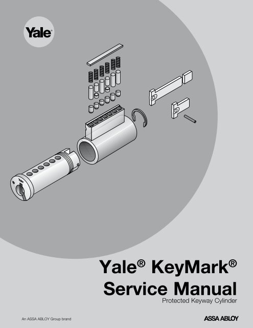
Yale ® KeyMark ®<br />
<strong>Service</strong> <strong>Manual</strong><br />
Protected Keyway Cylinder<br />
An <strong>ASSA</strong> <strong>ABLOY</strong> Group brand
Yale ® KeyMark ® service manual protected keyway cylinders<br />
table of contents<br />
The <strong>Security</strong> Leg ® .................................................................................... 2<br />
Cylinder Exploded Views and Part Numbers .............................................................. 3-6<br />
Parts Breakdown. .................................................................................... 7<br />
Pin Specifications .................................................................................... 8<br />
Pins and Pin Kits ..................................................................................... 9<br />
Key Bitting Specifications ............................................................................. 10<br />
Key Cutting ........................................................................................ 11<br />
Key Cutting Log .................................................................................... 12<br />
Combinating Cylinders ............................................................................... 13<br />
Combinating Worksheets .......................................................................... 14-17<br />
Master Keying ................................................................................... 18-19<br />
protected keyway<br />
The <strong>Security</strong> Leg<br />
The Yale KeyMark keyway has three distinct components: an upper portion or blade, a middle ledge, and a unique, lower angled<br />
portion or leg which exits the plug at an angle. This <strong>Security</strong> Leg keyway offers these advantages:<br />
1. Keyway differentiation by angle;<br />
2. Increased pick resistance;<br />
3. Prevents other manufacturers’ or other angle users’ keys from entering the cylinder;<br />
4. A unique and strong key with true key control;<br />
5. A key blank of added thickness for extra strength and durability;<br />
6. Prevents duplication of keys on standard key machines.<br />
BLADE<br />
LEDGE<br />
SECURITY LEG<br />
MILLING FOR KEYWAY WARDS<br />
2
Yale ® KeyMark ® service manual protected keyway cylinders<br />
mortise/rim cylinders<br />
Item Description Qty.<br />
Mortise<br />
Model No.<br />
Rim<br />
Model No.<br />
Remarks<br />
1 Mortise Plug-.511" 1 K150 NA Length, keyway and finish required<br />
2 Shell 1 K151 K351 Finish required<br />
3 Cam 1 KC1 NA KC1 standard, refer to page 7 for options<br />
4 Cam Washer 1 KP1 NA<br />
5 Cam Screw 2 KP2 NA<br />
6 Bottom Pins<br />
* * *<br />
Refer to page 9 for options<br />
7 Top Pins (Master)<br />
* * *<br />
Refer to page 9 for options<br />
8 Top Pins (Driver)<br />
* * *<br />
Refer to page 9 for options<br />
9 Tumbler Springs 6 or 7 K730 K730<br />
10 Set Screws 6 or 7 K736 K736<br />
11 Plug Retainer 1 NA K739<br />
12 Rim Plug-.511" Plug Diameter 1 NA K350 Finish & keyway required<br />
13 Collar 1 NA KP4 Finish required<br />
14 Mounting Plate 1 NA Yale ® Part 34-0010-1015-059<br />
15 Mounting Screws 2 NA Yale Part 34-2311-8738-048<br />
16 Tailpiece (Break-off) 1 NA KT1 Includes tailpiece retainer<br />
17 Tailpiece Retainer 1 NA<br />
*<br />
Included with tailpiece<br />
* See remarks.<br />
3
Yale ® KeyMark ® service manual protected keyway cylinders<br />
small format interchangeable core<br />
13<br />
12<br />
11<br />
10<br />
4<br />
9<br />
5<br />
8<br />
6<br />
3<br />
7<br />
2<br />
1<br />
YA KM SFIC EXPLOD.EPS<br />
ITEM Description Qty. Catalog No. Remarks<br />
1 Shell 1<br />
**<br />
Not available separately<br />
2 Pin Ejector Holes 6 or 7<br />
*<br />
For location information only<br />
3 Control Sleeve 1<br />
**<br />
Not available separately<br />
4 Control Lug 1<br />
**<br />
Not available separately<br />
5 Plug - .434" Plug Diameter 1<br />
**<br />
Not available separately<br />
6 Rivet Posts<br />
* **<br />
Not available separately<br />
7 Key Stop Back Plate 1<br />
**<br />
Not available separately<br />
8 Bottom Pins<br />
* *<br />
Refer to page 9 for options<br />
9 Top Pins (Master)<br />
* *<br />
Refer to page 9 for options<br />
10 Top Pins (Build-up)<br />
* *<br />
Refer to page 9 for options<br />
11 Top Pins (Driver)<br />
* *<br />
Refer to page 9 for options<br />
12 Tumbler Springs 6 or 7 K730<br />
13 Pin Chamber Caps 6 or 7 K731<br />
* See remarks.<br />
**Parts included in K600, not available ordered separately.<br />
4
Yale ® KeyMark ® service manual protected keyway cylinders<br />
large format interchangeable core<br />
7<br />
12<br />
11<br />
10<br />
9<br />
8<br />
5<br />
6<br />
2<br />
4<br />
3<br />
Item Description Qty. Catalog No. Remarks<br />
YA KM LFIC EXPLOD.eps<br />
1 Plug - .511" Plug Diameter 1 K850 No. of pins, keyway and finish required<br />
2 Control Pin and Spring 1<br />
*<br />
Staked in place<br />
3 Shell 1 K851<br />
No. of pins and finish required<br />
Includes items 5, 6 and 7<br />
4 Plug Retainer 1 K740<br />
5 Control Lug 1<br />
*<br />
Not available separately<br />
6 Control Lug Retainer Screw 1<br />
*<br />
Not available separately<br />
7 Control Lug Guide Pin and Spring 1<br />
*<br />
Not available separately<br />
8 Bottom Pins<br />
* *<br />
Refer to page 9 for options<br />
9 Top Pins (Master)<br />
* *<br />
Refer to page 9 for options<br />
10 Top Pins (Driver)<br />
* *<br />
Refer to page 9 for options<br />
11 Tumbler Springs 6 or 7 K730<br />
12 Spring Cover, 6-pin 1 K732<br />
12 Spring Cover, 7-pin 1 K733<br />
* See remarks.<br />
5
Yale ® KeyMark ® service manual protected keyway cylinders<br />
key-in-knob/lever cylinders<br />
7<br />
6<br />
5<br />
11<br />
10<br />
12<br />
4<br />
3<br />
8<br />
9<br />
2<br />
1<br />
YA KM KNOB EXPL.EPS<br />
Item Description Qty. Key-In-Knob Model No. Key-in-Lever Model No.<br />
1 Plug - .511" Plug 1 K450 K450<br />
2 Shell 1 K451 K451<br />
3 Bottom Pins<br />
* * *<br />
4 Top Pins (Master)<br />
* * *<br />
5 Top Pins (Driver)<br />
* * *<br />
6 Tumbler Springs 6 or 7 K730 K730<br />
7 Spring Cover, 6-pin 1 K734 K734<br />
7 Spring Cover, 7-pin 1 K735 K735<br />
8 Plug Retainer 1 K741 K741<br />
9 Roll Pin 1 NA Yale ® Part<br />
10 Tailpiece 1 NA KT2<br />
11 Tailpiece 1 NA KT7<br />
12 Tailpiece 1 NA KT3<br />
Note: Tailpiece length varies by function and application.<br />
* See remarks.<br />
Auxiliary Cylinders (Not Illustrated)<br />
The items in the chart at right are specific to<br />
auxiliary cylinders. Item numbers 2 through<br />
8 above are also included.<br />
Description Qty. Model No. Remarks<br />
Plug 1 K251 Used with K200<br />
Tailpiece 1 KT4 Used with K200<br />
Tailpiece 1 KT6 Used with K290 only<br />
Cylinder Collar 1 Yale Part 14-3511-1013-048<br />
Lazy Cam 1 Yale Part 14-3511-6102-082<br />
D-Ring 1 Yale Part 14-3511-1014-048<br />
Note: Tailpiece length varies by function and application.<br />
6
Yale ® KeyMark ® service manual protected keyway cylinders<br />
parts breakdown<br />
Cylinder Parts<br />
Number Description Used With Remarks<br />
K730 Tumbler Springs All types<br />
K731 Pin Chamber Caps K600 SFIC<br />
K732 Spring Cover, 6-pin K800 LFIC<br />
K733 Spring Cover, 7-pin K800 LFIC<br />
K734 Spring Cover, 6-pin K200/K400 Aux./KIK/KIL<br />
K735 Spring Cover, 7-pin K200/K400 Aux./KIK/KIL<br />
K736 Set Screws K100/K300 Mortise/Rim<br />
K739 Plug Retainer K300 Rim<br />
K740 Plug Retainer K800 LFIC<br />
K741 Plug Retainer K200/K400 Aux./KIK/KIL<br />
Tailpieces<br />
Length Varies by Function and Application<br />
Number Used With Remarks<br />
KT1 K300/K840 Rim/LFIC Rim<br />
KT2 K402 6-pin KIL<br />
KT3 K404 KIL<br />
KT4 K200 Auxiliary<br />
KT5 K490 Schlage ® KIL Kit<br />
KT8 K202 6-Pin Interconnected<br />
Lock<br />
Plugs<br />
Length, Keyway and Finish Required<br />
Number Used With Remarks<br />
K150 K100 Mortise<br />
K250 K200 Auxiliary<br />
K350 K300 Rim<br />
K450 K400 KIK/KIL<br />
K850 K800 LFIC<br />
Cams<br />
Number<br />
Yale Reference<br />
KC1 2160<br />
KC2 2130<br />
KC3 1161/Schlage Straight<br />
KC4 1160<br />
KC5 1161 (AR)<br />
KC6 1161G (Key Switch)<br />
KC7 Schlage Cloverleaf<br />
KC8 Corbin Russwin Cloverleaf (A01)<br />
KC9 Sargent ® Straight<br />
KC10 Yale ® Affinity ®<br />
Shells<br />
Length and Finish Required Where Applicable<br />
Number Used With Remarks<br />
K151 K100 Mortise<br />
K351 K300 Rim<br />
K451 K200/K400 Aux./KIK/KIL<br />
Number<br />
KP1<br />
KP2<br />
Cam Accessories<br />
Description<br />
Cam Washer<br />
Cam Screws<br />
Lubrication<br />
Yale ® KeyMark ® cylinders are lubricated from the factory with a Teflon ® lubrication. Cylinders should be lubricated periodically<br />
depending upon environmental conditions and usage. LAB Lube is the approved lubricant.<br />
Caution: It is not recommended to lubricate cylinders with oil or to mix lubricants.<br />
7
Yale ® KeyMark ® service manual protected keyway cylinders<br />
pin specifications<br />
Yale ® KeyMark ® cylinders use selected top and bottom pins that are spool type for added security. While other manufacturers’<br />
pin kits can be used with Yale KeyMark cylinders, the strict tolerances of pins and the added security from the spool pins are<br />
good reasons to use original Yale KeyMark pins. Also, use of non-factory original pins can void the warranty.<br />
To minimize the possibility of decoding the cylinder combination by reading the color of the<br />
pins, never use colored replacement pins.<br />
Bottom pins are made of high-quality nickel silver. This distributes wear evenly between the<br />
key and the pins.<br />
Top, build-up and master pins are made of brass.<br />
• Pin increment is .0125"<br />
• Pin diameter is .1085"<br />
• Bottom pin tip flat is .015"<br />
• Bottom pin crown is 45° x .008"; Top pin crown is 30° x .008"<br />
• Total stack height is:<br />
.3975" for small format interchangeable core cylinders (23)<br />
.2375" for non-small format interchangeable core cylinders (19)<br />
2<br />
3<br />
4<br />
5<br />
6<br />
7<br />
8<br />
9<br />
10<br />
Size<br />
Master, Build-up &<br />
Top Pins<br />
Length<br />
Model<br />
Number<br />
2 .025" K702<br />
3 .037" K703<br />
4 .050" K704<br />
5 .062" K705<br />
6 (Spool) .075" K706<br />
7 .087" K707<br />
8 (Spool) .100" K708<br />
9 .112" K709<br />
10<br />
(Spool)<br />
.125" K710<br />
11 .137" K711<br />
12 .150" K712<br />
13 .162" K713<br />
14 .175" K714<br />
15 .187" K715<br />
16 .200" K716<br />
17 .212" K717<br />
18 .225" K718<br />
19 .237” K719<br />
11 12 13 14 15 16 17 18 19<br />
Master, Build-up and Top Pins<br />
YA KM TOP PINS.eps<br />
0 1 2 3 4 5 6 7 8 9<br />
Bottom Pins<br />
YA KM BOTTOM PINS.eps<br />
Size<br />
Bottom Pins<br />
Length<br />
Model<br />
Number<br />
0 .110" K720<br />
1 .122" K721<br />
2 .135" K722<br />
3 .147" K723<br />
4 .160" K724<br />
5 .172" K725<br />
6 .185" K726<br />
7 (Spool) .197" K727<br />
8 (Spool) .210" K728<br />
9 (Spool) .222" K729<br />
8
Yale ® KeyMark ® service manual protected keyway cylinders<br />
pin kits<br />
K918<br />
Length Bottom Master Build-Up Top Pin Kit Qty.<br />
.025" 2 100<br />
.037" 3 100<br />
.050" 4 100<br />
.062" 5 100<br />
.075" 6 100<br />
.087" 7 100<br />
.100" 8 100<br />
.110" 0 100<br />
.112" 9 100<br />
.122" 1 100<br />
.125" 10 100<br />
.135" 2 100<br />
.137" 11 100<br />
.147" 3 100<br />
.150" 12 100<br />
.160" 4 100<br />
.162" 13 100<br />
.172" 5 100<br />
.175" 14 100<br />
.185" 6 100<br />
.187" 15 100<br />
.197” 7 100<br />
.200” 16 100<br />
.210” 8 100<br />
.212” 17 100<br />
.222” 9 100<br />
.225” 18 100<br />
.237” 19 100<br />
Description<br />
Pin Kit Contents<br />
Model<br />
Number<br />
Pin Kit<br />
Used<br />
With<br />
Tumbler Springs K730 100 All<br />
Pin Chamber Caps K731 25 K600<br />
Spring Cover, 6-pin K732 25 K800<br />
Spring Cover, 7-pin K733 25 K800<br />
9
Yale ® KeyMark ® service manual protected keyway cylinders<br />
key bitting specifications<br />
Applies to all Yale ® Keymark ® keyways<br />
“A2” PINNING<br />
SPECIFICATIONS<br />
1. 095"<br />
.945" 1. 095"<br />
.795" .945"<br />
.645" .795"<br />
.495" .645"<br />
.345" .495" 90<br />
.195" .345" .054"<br />
90<br />
.195" .054"<br />
7 6 5 4 3 2 1<br />
SPACING FROM THE SHOULDER<br />
7 6 5 4 3 2 1<br />
SPACING FROM THE SHOULDER<br />
MACS: 9<br />
Increment: .0125"<br />
Progression:<br />
Two Step<br />
Blade Width: .310"<br />
Depth Tolerance: ±0.0015"<br />
Spacing Tolerance: ±0.0010"<br />
0-.1385"<br />
1-.1260"<br />
0-.1385"<br />
2-.1135"<br />
1-.1260"<br />
3-.1010"<br />
2-.1135"<br />
4-.0885"<br />
3-.1010"<br />
5-.0760"<br />
4-.0885"<br />
6-.0635"<br />
5-.0760"<br />
7-.0510"<br />
6-.0635"<br />
8-.0385"<br />
7-.0510"<br />
9-.0260"<br />
8-.0385"<br />
.0000"<br />
9-.0260"<br />
.0000"<br />
.990"<br />
.990"<br />
.840"<br />
.840" .690"<br />
.690" .540"<br />
.540" .390"<br />
.240"<br />
.390"<br />
90 .240"<br />
.054"<br />
90<br />
.054"<br />
.090"<br />
.090"<br />
7 6 5 4 3 2 1<br />
SPACING FROM THE TIP<br />
7 6 5 4 3 2 1<br />
SPACING FROM THE TIP<br />
All Cuts Are Read and Written TIP to BOW<br />
All depths are referenced from the offset or ledge of the key rather than from the bottom of the blade.<br />
0-.1385"<br />
1-.1260"<br />
0-.1385"<br />
2-.1135"<br />
1-.1260"<br />
3-.1010"<br />
2-.1135"<br />
4-.0885"<br />
3-.1010"<br />
5-.0760"<br />
4-.0885"<br />
6-.0635"<br />
5-.0760"<br />
7-.0510"<br />
6-.0635"<br />
8-.0385"<br />
7-.0510"<br />
9-.0260"<br />
8-.0385"<br />
.0000"<br />
9-.0260"<br />
.0000"<br />
10<br />
KEY BITTING SPECS .eps<br />
KEY BITTING SPECS .eps
Yale ® KeyMark ® service manual protected keyway cylinders<br />
key cutting<br />
K900 Code Cutting Punch<br />
n Automatic Key Advance<br />
n Interchangeable Vise Assembly<br />
1<br />
4<br />
2<br />
3<br />
YA KM CODE CUTTING PUNCH<br />
Keys should only be cut using the Yale ® KeyMark ® K900 Code Cutting punch or other approved machines. These machines and<br />
special vises are only available through Yale.<br />
Each code punch machine is designed to cut only the unique angle of Yale Keymark keys.<br />
Any inserts or jaws for other machines, available in the future, will also only be available through Yale.<br />
The K900 Code Cutting Punch can rest on a work bench or it can be mounted securely to the bench by means of the two<br />
mounting holes located in the base.<br />
Note: The code punch uses a tip reference and all keys are cut tip to bow. LFIC Control Keys are furnished pre-cut in the tip<br />
position. When referencing the bitting list, the “0” cut used on the tip bitting is only to advance the vise one position.<br />
When cutting these keys:<br />
1. Insert the keyblank into the vise assembly.<br />
2. Turn the depth knob to “0” and depress the paddle handle.<br />
This will advance the vise assembly to the correct starting position for cutting the key.<br />
3. Continue with cutting the key depths.<br />
1. Depth Knob<br />
2. Paddle Handle<br />
3. Mounting Holes<br />
4. Vise Assembly<br />
11
Yale ® KeyMark ® service manual protected keyway cylinders<br />
key cutting log<br />
COMPANY/FACILITY NAME<br />
BEGINNING INVENTORY<br />
KEY BLANKS RECEIVED<br />
TOTAL CUT KEYS ISSUED<br />
KEYWAY<br />
SYSTEM REGISTRY<br />
TOTAL MISCUT KEYS<br />
TOTAL ENDING INVENTORY<br />
Date<br />
No. of<br />
Cut<br />
Keys<br />
Issued<br />
No. of<br />
Miscut<br />
Facility Issued To - As per NOA<br />
Zip<br />
Code<br />
Key<br />
Machine<br />
Operator<br />
Total<br />
Blanks<br />
Used<br />
Balance<br />
of<br />
Keys<br />
Notes<br />
12
Yale ® KeyMark ® service manual protected keyway cylinders<br />
combinating cylinders<br />
Calculating the “A2” Pin Stack<br />
Rules For Top Loading<br />
K600 (SFIC) Cylinders<br />
SFIC<br />
• K600<br />
Non-SFIC<br />
• All Other Types<br />
For best results, pin the cylinder one chamber at a time.<br />
• Pin the cylinder to the operating keys – change key(s) and<br />
master keys(s) – using bottom and master pins<br />
• Pin the cylinder to the control key by inserting a “build-up<br />
pin” in each chamber. To determine the build-up pin<br />
numbers:<br />
• Add 10 to each of the control key cuts. This is called the<br />
“control total”;<br />
• For each chamber, subtract the bottom pin and<br />
master pin total (plug total) from the control total;<br />
• Use the resulting number as your build-up pin<br />
number.<br />
• Load the top pin. To determine the top pin number,<br />
subtract the control total from 23. Reference the “Quick<br />
Subtraction Chart” for quick calculation (see page 15).<br />
• The total stack height (the sum of all the pins) must<br />
equal 23.<br />
• After all chambers have been pinned, insert the core into the<br />
capping block, load springs, and cap.<br />
Rules For Top Loading K100/K200/K300/K400/K800<br />
(Non-SFIC) Cylinders<br />
For best results, pin the cylinder one chamber at a time.<br />
Top Pin =<br />
23<br />
Minus<br />
The<br />
Control<br />
Total<br />
Build-up<br />
Pin =<br />
The Control<br />
Total<br />
Minus<br />
The Plug<br />
Total<br />
Master Pin<br />
(if req.)=<br />
The Deep<br />
Minus The<br />
Shallowest<br />
Operating<br />
Cut<br />
Bottom<br />
Pin =<br />
The<br />
Shallowest<br />
Operating<br />
Cut<br />
Plug Total =<br />
The<br />
Bottom Pin<br />
Plus<br />
The<br />
Master Pin<br />
Top Pin =<br />
19<br />
Minus<br />
Plug Total<br />
Master Pin<br />
(if req.)=<br />
The Deep<br />
Minus The<br />
Shallowest<br />
Operating<br />
Cut<br />
Bottom<br />
Pin =<br />
The<br />
Shallowest<br />
Operating<br />
Cut<br />
• Pin the cylinder to the operating keys – change key(s) and master<br />
keys(s) – using bottom and master pins<br />
• Load the top pin. To determine the top pin number,<br />
subtract the bottom pin and master pin total (plug total) from<br />
19. Reference the “Quick Subtraction Chart” for quick calculation<br />
(see page 17).<br />
• The total stack height (the sum of all the pins) must equal 19.<br />
• After all chambers have been pinned, insert the<br />
core/cylinder into the capping block, load springs, and cap.<br />
See page 14 & 15 for completed sample and blank combinating worksheets of SFIC cylinders.<br />
See page 16 & 17 for completed sample and blank combinating worksheets of Non-SFIC cylinders.<br />
13
Yale ® KeyMark ® service manual protected keyway cylinders<br />
combinating worksheet: K600 (SFIC)<br />
Completed Sample<br />
CALCULATION<br />
To verify: P1, P2, P3 & P4 in each chamber must add up to 23.<br />
TIP<br />
CHAMBERS<br />
OPERATING KEYS 1 2 3 4 5 6 7<br />
01 GGMK Insert Bitting — — — — — — —<br />
02 GMK A Insert Bitting 3 4 9 5 0 6<br />
03 MK AA Insert Bitting 5 2 9 5 0 6<br />
04 CK AA1 Insert Bitting 5 2 1 7 2 6<br />
P1» 05 Bottom Pin [Shallowest Operating Cut] 3 2 1 5 0 6<br />
P2» 06 Master Pin<br />
CONTROL KEY<br />
BUILD-UP PIN<br />
[Deepest Minus<br />
Shallowest Operating Cut]<br />
2 2 8 2 2 X<br />
07 Plug Total [Master Plus Bottom Total] 5 4 9 7 2 6<br />
C1 Control Cut Insert Bitting 1 6 5 9 8 2<br />
C2 Control Total [Add 10 to C1] 11 16 15 19 18 12<br />
B1 Control Total [C2] 11 16 15 19 18 12<br />
B2 Plug Total [07] 5 4 9 7 2 6<br />
P3» B3 Build-up Pin [Subtract B2 from B1] 6 12 6 12 16 6<br />
TOP PIN<br />
T1 Stack Height [Pre-set] 23 23 23 23 23 23 23<br />
T2 Control Total [B1] 11 16 15 19 18 12<br />
P4» T3 Top Pin [Subtract T2 from T1] 12 7 8 4 5 11<br />
PINNING SET UP<br />
(T3) P4» Top Pin 12 7 8 4 5 11<br />
(B3) P3» Build-up Pin 6 12 6 12 16 6<br />
(06) P2» Master Pin 2 2 8 2 2 X<br />
(05) P1» Bottom Pin 3 2 1 5 0 6<br />
BOW<br />
14
Yale ® KeyMark ® service manual protected keyway cylinders<br />
combinating worksheet: K600 (SFIC)<br />
Blank Worksheet<br />
CALCULATION<br />
To verify: P1, P2, P3 & P4 in each chamber must add up to 23.<br />
CHAMBERS<br />
OPERATING KEYS 1 2 3 4 5 6 7<br />
01 GGMK Insert Bitting<br />
02 GMK Insert Bitting<br />
03 MK Insert Bitting<br />
04 CK Insert Bitting<br />
P1» 05 Bottom Pin [Shallowest Operating Cut]<br />
P2» 06 Master Pin<br />
CONTROL KEY<br />
BUILD-UP PIN<br />
[Deepest Minus<br />
Shallowest Operating Cut]<br />
07 Plug Total [Master Plus Bottom Total]<br />
C1 Control Cut Insert Bitting<br />
C2 Control Total [Add 10 to C1]<br />
B1 Control Total [C2]<br />
B2 Plug Total [07]<br />
P3» B3 Build-up Pin [Subtract B2 from B1]<br />
TOP PIN<br />
TIP<br />
T1 Stack Height [Pre-set] 23 23 23 23 23 23 23<br />
T2 Control Total [B1]<br />
P4» T3 Top Pin [Subtract T2 from T1]<br />
PINNING SET UP<br />
(T3) P4» Top Pin<br />
(B3) P3» Build-up Pin<br />
(06) P2» Master Pin<br />
(05) P1» Bottom Pin<br />
BOW<br />
Quick Subtraction Chart<br />
Minus 1 2 3 4 5 6 7 8 9 10 11 12 13 14 15 16 17 18 19 20 21 22 23<br />
23 22 21 20 19 18 17 16 15 14 13 12 11 10 9 8 7 6 5 4 3 2 1 0<br />
15
Yale ® KeyMark ® service manual protected keyway cylinders<br />
combinating worksheet: K100/K200/K300/K400/K800 (Non-SFIC)<br />
Completed Sample<br />
CALCULATION<br />
To verify: P1, P2 & P3 in each chamber must add up to 19.<br />
TIP<br />
CHAMBERS<br />
OPERATING KEYS 1 2 3 4 5 6 7<br />
01 GGMK Insert Bitting — — — — — — —<br />
02 GMK A Insert Bitting 3 4 9 5 0 6<br />
03 MK AA Insert Bitting 5 2 9 5 0 6<br />
04 CK AA1 Insert Bitting 5 2 1 7 2 6<br />
P1» 05 Bottom Pin [Shallowest Operating Cut] 3 2 1 5 0 6<br />
P2» 06 Master Pin<br />
TOP PIN<br />
[Deepest Minus<br />
Shallowest Operating Cut]<br />
2 2 8 2 2 X<br />
07 Plug Total [Master Plus Bottom Total] 5 4 9 7 2 6<br />
T1 Stack Height [Pre-set] 19 19 19 19 19 19 19<br />
T2 Control Total [07] 5 4 9 7 2 6<br />
P4» T3 Top Pin [Subtract T2 from T1] 14 15 10 12 17 13<br />
PINNING SET UP<br />
(T3) P3» Top Pin 14 15 10 12 17 13<br />
(06) P2» Master Pin 2 2 8 2 2 X<br />
(05) P1» Bottom Pin 3 2 1 5 0 6<br />
BOW<br />
16
Yale ® KeyMark ® service manual protected keyway cylinders<br />
combinating worksheet: K100/K200/K300/K400/K800 (Non-SFIC)<br />
Blank Worksheet<br />
CALCULATION<br />
To verify: P1, P2 & P3 in each chamber must add up to 19.<br />
TIP<br />
CHAMBERS<br />
OPERATING KEYS 1 2 3 4 5 6 7<br />
01 GGMK Insert Bitting<br />
02 GMK Insert Bitting<br />
03 MK Insert Bitting<br />
04 CK Insert Bitting<br />
P1» 05 Bottom Pin [Shallowest Operating Cut]<br />
P2» 06 Master Pin<br />
TOP PIN<br />
[Deepest Minus<br />
Shallowest Operating Cut]<br />
07 Plug Total [Master Plus Bottom Total]<br />
T1 Stack Height [Pre-set] 19 19 19 19 19 19 19<br />
T2 Control Total [07]<br />
P4» T3 Top Pin [Subtract T2 from T1]<br />
PINNING SET UP<br />
(T3) P3» Top Pin<br />
(06) P2» Master Pin<br />
(05) P1» Bottom Pin<br />
BOW<br />
Quick Subtraction Chart<br />
Minus 1 2 3 4 5 6 7 8 9 10 11 12 13 14 15 16 17 18 19<br />
19 18 17 16 15 14 13 12 11 10 9 8 7 6 5 4 3 2 1 0<br />
17
Yale ® KeyMark ® service manual protected keyway cylinders<br />
master keying<br />
Standard Key Coding System<br />
Standard Master Key System:<br />
2 Levels of Keying<br />
Grand Master Key System:<br />
3 Levels of Keying<br />
Master key is assigned two letters. Change<br />
key numbers come before the MK letters.<br />
Grand master key is assigned one letter. Masters under the GMK<br />
are assigned two letters, the first being the same as the GMK letter.<br />
Change keys numbers come after the MK letters.<br />
MK<br />
AA<br />
GMK<br />
A<br />
CK<br />
1AA<br />
2AA<br />
3AA<br />
MK<br />
AA<br />
AB<br />
YA MK LEVEL2.eps<br />
CK<br />
AA1<br />
AA2<br />
AA3<br />
AB1<br />
AB2<br />
AB3<br />
Great Grand Master Key System: 4 Levels of Keying<br />
YA MK LEVEL3.eps<br />
Great grand master key has the symbol of GGM. Grand master keys are each assigned one letter. Masters under the GMK are<br />
assigned two letters, the first letter being the same as the GMK letter. Change key numbers come after the MK letters.<br />
GGMK<br />
GGM<br />
GMK<br />
A<br />
B<br />
MK<br />
AA<br />
AB<br />
BA<br />
BB<br />
CK<br />
AA1<br />
AA2<br />
AA3<br />
AB1<br />
AB2<br />
AB3<br />
BA1<br />
BA2<br />
BA3<br />
BB1<br />
BB2<br />
BB3<br />
Special Keying Situations<br />
YA MK LEVEL4.eps<br />
Cylinder is operated by the change key and GMK, but no MK: Change key numbers come after the single GMK letter. Example:<br />
A1, A2, B1, etc.<br />
Cylinder is operated by change key and GGM only, but no GMK or MK: Use symbols GGM1, GGM2, etc.<br />
Cylinder is operated by one of the system’s change keys but no MK’s of any level: Suffix “(NMK)” to the regular symbol.<br />
Example: 3AA(NMK), AA7(NMK), etc.<br />
Cylinder is operated by no keys in the system other than its own individual key: Single keyed sets SKD1, SKD2, etc.<br />
18
Yale ® KeyMark ® service manual protected keyway cylinders<br />
master keying<br />
GGMK<br />
GGM<br />
GMK<br />
A<br />
B<br />
MK<br />
AA<br />
AB<br />
BA<br />
BB<br />
CK<br />
AA1<br />
AA2<br />
A1<br />
AB1<br />
AB2<br />
GGM1<br />
BA1<br />
BA2<br />
B1<br />
BB1<br />
BB2<br />
SKD1<br />
Master Key System Specifications<br />
Refer to page 10 for the Key Bitting Specifications.<br />
YA MK LEVEL5.eps<br />
Expansion Specifications<br />
Yale ® KeyMark ® systems should include expansion specifications which indicate the maximum planned quantity of theoretical<br />
bitting combinations needed at each level of keying. The expansion specification is the arithmetic expression of the expansion in<br />
the form of numbers separated by dashes. Each number refers to the level of keying system to which it relates.<br />
Examples:<br />
For a 2-level system requiring fifty change keys, the expansion specification would be: 1-50<br />
For a 3-level system requiring two masters under the grand and forty change keys under each master, the expansion<br />
specification would be: 1-2-40<br />
For a 4-level system requiring three grands each with ten masters with fifty changes, the expansion specification would be: 1-3-<br />
10-50<br />
The number of changes needed directly operated by the GGM or GM is indicated in parenthesis after that level’s specification.<br />
For example: 1(10)-4-75 would be read “one grand master with four masters under the grand, seventy-five changes under each<br />
master, and ten changes directly under the grand master only.”<br />
The following charts are examples of master keying specifications for Yale KeyMark 6- and 7-pin master key systems:<br />
6-pin<br />
GGM GM MK CK<br />
Level 2 1 4096<br />
A 1 4 1024<br />
Level 3 B 1 16 256<br />
C 1 64 64<br />
A 1 4 4 256<br />
Level 4 B 1 4 16 64<br />
C 1 16 16 16<br />
7-pin<br />
GGM GM MK CK<br />
Level 2 1 16384<br />
A 1 4 4096<br />
Level 3 B 1 16 1024<br />
C 1 64 256<br />
A 1 4 4 1024<br />
Level 4 B 1 4 16 256<br />
C 1 16 16 64<br />
19
Yale ® KeyMark ® service manual protected keyway cylinders<br />
online literature and templates<br />
For the latest information on Yale Locks & Hardware products, visit our website at: www.yalelocks.com<br />
Click on the “Product Information” button to find:<br />
• Catalogs<br />
• Parts manuals<br />
• Templates<br />
• Specifications<br />
• Installation instructions<br />
Yale ® customers can click on the ebusiness symbol<br />
on the website to register for an ebusiness account to:<br />
• Check the status of orders<br />
• Check availability of Quick-Ship items<br />
• Track your order and confirm delivery<br />
• Receive email notification of template changes<br />
And More...<br />
Or contact us at:<br />
U.S.A.<br />
Yale Locks & Hardware<br />
Address:100 Yale Avenue, Lenoir City, TN 37771-3226<br />
Tel: 1-800-438-1951 • Fax: 1-800-338-0965 • www.yalelocks.com<br />
Canada:<br />
<strong>ASSA</strong> <strong>ABLOY</strong> <strong>Door</strong> <strong>Security</strong> Solutions Canada<br />
Address:160 Four Valley Drive, Vaughan, Ontario L4K 4T9<br />
Tel: 1-800-461-3007 • Fax: 1-800-461-8989 • www.assaabloy.ca<br />
International:<br />
<strong>ASSA</strong> <strong>ABLOY</strong> Americas International<br />
Tel: 1-905-821-7775 • Fax: 1-905-821-1429 • www.assaabloyai.com<br />
Yale Locks & Hardware is a division of Yale <strong>Security</strong> Inc., an <strong>ASSA</strong> <strong>ABLOY</strong> Group company.<br />
Yale® is a registered trademark of Yale <strong>Security</strong> Inc., an <strong>ASSA</strong> <strong>ABLOY</strong> Group company. KeyMark®, Medeco®, and <strong>Security</strong> Leg® are registered trademarks of Medeco <strong>Security</strong> Locks, Inc.<br />
Schlage® is a registered trademark of Schlage Lock Company. Sargent® is a registered trademark of Sargent Manufacturing Company. Other products' brand names may be trademarks<br />
or registered trademarks of their respective owners and are mentioned for reference purposes only. These materials are protected under U.S. copyright laws. All contents current at time of<br />
publication. Yale <strong>Security</strong> Inc. reserves the right to change availability of any item in this catalog, its design, construction, and/or its materials. Copyright © 2002, 2011, Yale <strong>Security</strong> Inc., an<br />
<strong>ASSA</strong> <strong>ABLOY</strong> Group company. All rights reserved. Reproduction in whole or in part without the express written permission of the Yale <strong>Security</strong> Inc., an <strong>ASSA</strong> <strong>ABLOY</strong><br />
Group company. is prohibited.<br />
YALE, with its unique global reach and range of products, is the world’s favorite lock.<br />
<strong>ASSA</strong> <strong>ABLOY</strong> is the global leader in door opening solutions, dedicated to satisfying end-user needs for security, safety and convenience.<br />
42250-5/11RE<br />
An <strong>ASSA</strong> <strong>ABLOY</strong> Group brand


![Simplex 9600 Parts List [PDF] - Kaba Ilco](https://img.yumpu.com/11675680/1/190x245/simplex-9600-parts-list-pdf-kaba-ilco.jpg?quality=85)

![Plus Box Software Update Instructions[PDF] - Kaba Ilco](https://img.yumpu.com/7807944/1/190x245/plus-box-software-update-instructionspdf-kaba-ilco.jpg?quality=85)