Install. Man.-TC - Salvajor
Install. Man.-TC - Salvajor
Install. Man.-TC - Salvajor

Create successful ePaper yourself
Turn your PDF publications into a flip-book with our unique Google optimized e-Paper software.
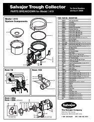
DIFFUSER<br />
#980061<br />
TROUGH SECTION<br />
Trough Recirculation<br />
Plumb 1 1 ⁄2” pipe from the 1 1 ⁄2” rubber coupler<br />
supplied on the end of the Collector unit to<br />
the far end of the fabricated trough and<br />
attach it to the water diffuser.<br />
#TVD3 GASKET*<br />
#TVD2 LOCKNUT*<br />
1 1 /2" FEMALE<br />
THREAD to 1 1 /2"<br />
SWEAT FITTING<br />
ADAPTER (NF)<br />
1 1 /2" PIPING (NF)<br />
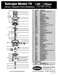
If optional gusher heads are to be mounted<br />
along the fabricated trough for scrapping and<br />
preflushing, they should be connected to the<br />
main 1 1 ⁄2” recirculation line reducing to 3/4”<br />
45˚<br />
1 1 /2" UNION (NF)<br />
4<br />
GUSHER HEAD (OPTIONAL)<br />
Ø1 5 /16" HOLE REQUIRED<br />
3 /4" PIPING (NF)<br />
3 /4" VALVE (NF)<br />
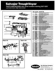
The closed end of the fabricated trough should have a minimum<br />
depth of 3” and a fall of at least 3/32” per running foot so that<br />
there will be adequate drainage to the Trough Collector machine.<br />
The open end of the fabricated trough should have a flange<br />
opening to match the flange opening on the Trough Collector.<br />
The two flange openings are to be butted together and securely<br />
welded.<br />
A 1 1 ⁄2” valve must be installed as close to the<br />
end of the fabricated trough as possible to<br />
regulate pump flow capacity.<br />
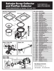
5 1 /2"<br />
(13.97)<br />
DIFFUSER<br />
Ø2" HOLE<br />
REQUIRED<br />
1 1 /2" VALVE (NF)<br />
with a 3/4” valve in each gusher head line<br />
to regulate the flow. Configure gusher head<br />
plumbing as shown to reduce splash when<br />
starting Trough Collector.<br />
MAKE ALL PLUMBING CONNECTIONS IN ACCORDANCE<br />
WITH NATIONAL AND LOCAL PLUMBING CODES.<br />
5 3 /4"<br />
(14.61)<br />
4"<br />
(10.16)<br />
8 3 /4"<br />
(22.23)<br />
A 2” diameter hole is required at the closed<br />
end of the trough for the factory furnished<br />
water diffuser which ensures a proper water<br />
flow pattern down the trough.<br />
Center the 2” diameter hole 1 1 ⁄4” from the<br />
bottom of the trough. A 1 1 ⁄2” union can be used<br />
instead of the 1 1 ⁄2” sweat fitting when the<br />
plumbing will need to be disconnected.