Install. Man.-TC - Salvajor
Install. Man.-TC - Salvajor
Install. Man.-TC - Salvajor

You also want an ePaper? Increase the reach of your titles
YUMPU automatically turns print PDFs into web optimized ePapers that Google loves.
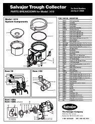
<strong>Salvajor</strong> Trough Collector<br />
Model S419<br />
Trough Conveying and Food Waste Collecting System<br />
Trough Collector<br />
Model S419<br />
2 Typical <strong>Install</strong>ations and Table Cutout<br />
3 Trough Collector <strong>Install</strong>ation & Location<br />
4 Trough Recirculation<br />
Warranty and Reply Card<br />
5 Plumbing<br />
6 Electrical<br />
7 Operating Instructions<br />
8 How it Works<br />
ALL INSTALLATIONS SHOULD BE MADE IN ACCORDANCE WITH<br />
LOCAL AND NATIONAL PLUMBING AND ELECTRICAL CODES.<br />
The <strong>Salvajor</strong> Company 4530 East 75th Terrace Kansas City, Missouri 64132-2081, USA<br />
1-888-SALVAJOR FAX: 1-800-832-9373<br />
www.salvajor.com Email: sales@salvajor.com service@salvajor.com<br />
<strong>Man</strong>ufacturers of Commercial Food Waste Disposing Systems since 1944<br />
<strong>Install</strong>ation &Operating<br />
INSTRUCTIONS
Typical Trough Collector <strong>Install</strong>ations<br />
Model S419<br />
12"<br />
(30.48)<br />
Allow 3’ between gusher<br />
heads to accomodate one<br />
operator per gusher head.<br />
A standard 5 3 ⁄4” trough should<br />
not exceed 16’ in length.<br />
A 12” wide trough should<br />
not exceed 14’ in length.<br />
5 3 /4"<br />
(14.61)<br />
2'<br />
Conveys waste into a collection basket.<br />
Trough design for multiple operators.<br />
2<br />
12 1 /4"<br />
(31.11)<br />
3'<br />
MINIMUM<br />
14'<br />
ø20"<br />
(ø50.75)<br />
14'<br />
12"<br />
(30.48)<br />
3'<br />
MINIMUM<br />
6 1 /2"<br />
(16.51)<br />
Weld the Collector top into the table using<br />
the above dimensions for the table cut out.
Trough Collector <strong>Install</strong>ation and Location<br />
It may be necessary to move the control from the back to the front of theTrough Collector<br />
depending on orientation in the table. This is easily accomplished using the existing<br />
fasteners, mounting holes and wiring.<br />
CONTROL CONTROL<br />
If necessary, the control can<br />
be mounted remotely using<br />
an optional bracket.<br />
Note: additional field wiring<br />
is necessary.<br />
CONTROL<br />
3<br />
The top of the Collector rotates<br />
in 15 degree increments to ease<br />
installation while keeping the<br />
tank and control square with<br />
the front of the table. It can be<br />
installed 180 degrees.<br />
60˚<br />
90˚<br />
180˚
DIFFUSER<br />
#980061<br />
TROUGH SECTION<br />
Trough Recirculation<br />
Plumb 1 1 ⁄2” pipe from the 1 1 ⁄2” rubber coupler<br />
supplied on the end of the Collector unit to<br />
the far end of the fabricated trough and<br />
attach it to the water diffuser.<br />
#TVD3 GASKET*<br />
#TVD2 LOCKNUT*<br />
1 1 /2" FEMALE<br />
THREAD to 1 1 /2"<br />
SWEAT FITTING<br />
ADAPTER (NF)<br />
1 1 /2" PIPING (NF)<br />
If optional gusher heads are to be mounted<br />
along the fabricated trough for scrapping and<br />
preflushing, they should be connected to the<br />
main 1 1 ⁄2” recirculation line reducing to 3/4”<br />
45˚<br />
1 1 /2" UNION (NF)<br />
4<br />
GUSHER HEAD (OPTIONAL)<br />
Ø1 5 /16" HOLE REQUIRED<br />
3 /4" PIPING (NF)<br />
3 /4" VALVE (NF)<br />
The closed end of the fabricated trough should have a minimum<br />
depth of 3” and a fall of at least 3/32” per running foot so that<br />
there will be adequate drainage to the Trough Collector machine.<br />
The open end of the fabricated trough should have a flange<br />
opening to match the flange opening on the Trough Collector.<br />
The two flange openings are to be butted together and securely<br />
welded.<br />
A 1 1 ⁄2” valve must be installed as close to the<br />
end of the fabricated trough as possible to<br />
regulate pump flow capacity.<br />
5 1 /2"<br />
(13.97)<br />
DIFFUSER<br />
Ø2" HOLE<br />
REQUIRED<br />
1 1 /2" VALVE (NF)<br />
with a 3/4” valve in each gusher head line<br />
to regulate the flow. Configure gusher head<br />
plumbing as shown to reduce splash when<br />
starting Trough Collector.<br />
MAKE ALL PLUMBING CONNECTIONS IN ACCORDANCE<br />
WITH NATIONAL AND LOCAL PLUMBING CODES.<br />
5 3 /4"<br />
(14.61)<br />
4"<br />
(10.16)<br />
8 3 /4"<br />
(22.23)<br />
A 2” diameter hole is required at the closed<br />
end of the trough for the factory furnished<br />
water diffuser which ensures a proper water<br />
flow pattern down the trough.<br />
Center the 2” diameter hole 1 1 ⁄4” from the<br />
bottom of the trough. A 1 1 ⁄2” union can be used<br />
instead of the 1 1 ⁄2” sweat fitting when the<br />
plumbing will need to be disconnected.
WATER SUPPLY<br />
The solenoid valve is factory installed and<br />
is attached to an automatic water blender<br />
which will introduce water tempered to<br />
approximately 107˚ F.<br />
Plumbing<br />
SOLENOID<br />
WATER BLENDER<br />
INCOMING WATER<br />
1 /2" BALL VALVES<br />
DRAIN PIPING<br />
Plumb a 2” pipe from the 2” male threaded<br />
nipple located on the bottom of the Collector<br />
reservoir tank to the nearest approved drain.<br />
The drain line should have a minimum of<br />
1/4” slope of fall per running foot. It is the<br />
responsibility of the plumbing contractor to<br />
check all connections to ensure they are<br />
free of leaks.<br />
5<br />
Plumb 3/4" lines from both hot and cold<br />
water supply sources and reduce to 1/2"<br />
before attaching to corresponding valves<br />
on the Trough Collector water harness.<br />
2" NPT DRAIN<br />
AIR<br />
GAP<br />
IMPORTANT:<br />
The <strong>Salvajor</strong> Trough Collector is equipped<br />
with a UPC approved air gap, eliminating<br />
the need for vacuum breakers.<br />
NOTE:<br />
To assure against leaks, tighten water<br />
harness fittings. They may come loose<br />
during shipment, fabrication or installation.<br />
Pressure regulators should be installed in<br />
areas where water pressure exceeds the<br />
recommended maximum of 80 psi.<br />
MAKE ALL PLUMBING CONNECTIONS IN ACCORDANCE<br />
WITH NATIONAL AND LOCAL PLUMBING CODES.
ELECTRICAL<br />
The pump motor and solenoid are factory<br />
pre-wired.<br />
Only one electrical connection is required<br />
if the control is installed with the provided<br />
wiring and mount. Run power from the<br />
building source to the 1/2" knockout on<br />
the bottom of the control.<br />
INCOMING POWER<br />
1 /2" CONDUIT<br />
PUMP<br />
IMPORTANT:<br />
The pump must be checked for<br />
proper rotation.<br />
Always use watertight conduit and<br />
fittings when wiring this product.<br />
Electrical<br />
MAKE ALL INSTALLATIONS IN ACCORDANCE<br />
WITH LOCAL AND NATIONAL ELECTRICAL CODES.<br />
6<br />
The control may be mounted remotely with<br />
an optional bracket. Additional wiring is<br />
necessary to connect the pump motor and<br />
solenoid to the control.<br />
Complete wiring diagrams will be found<br />
inside control panel.<br />
TOTAL FULL LOAD AMPS<br />
PHASE 115V 208V 230V 460-480V<br />
1 PH 11 5.5 5.5 –<br />
3 PH – 3.2 3 1.5<br />
PUMP MOTOR 3/4 HP
CONTROL<br />
PANEL<br />
Operating Instructions<br />
TO START:<br />
●1 Place OVERFLOW PIPE into drain<br />
opening in bottom of tank (center hole).<br />
●2 Position SCRAP BASKET inside tank.<br />
●3 Position SALVAGE BASIN inside tank<br />
over SCRAP BASKET.<br />
●4 Press START button on CONTROL<br />
PANEL. Allow time for reservoir tank<br />
to fill and maintain a constant flow of<br />
water down the trough.<br />
●5 Adjust the RECIRCULATION VALVE<br />
to regulate the flow of water down<br />
the trough.<br />
●6 If gusher heads are being used along<br />
the trough, adjust the GUSHER HEAD<br />
VALVES individually to the desired<br />
settings.<br />
4 A<br />
7<br />
TO STOP:<br />
●A Press STOP button on the CONTROL<br />
PANEL.<br />
●B Check for and remove dropped tableware<br />
trapped in SALVAGE BASIN.<br />
●C Remove and drain SALVAGE BASIN.<br />
●D Remove SCRAP BASKET and dump<br />
waste into trash receptacle.<br />
●E Remove OVERFLOW PIPE to drain tank.<br />
Rinse SALVAGE BASIN, SCRAP<br />
BASKET, OVERFLOW PIPE, and tank<br />
interior thoroughly.<br />
3 SALVAGE<br />
BASIN<br />
B C<br />
2<br />
D<br />
1<br />
E<br />
SCRAP<br />
BASKET<br />
OVERFLOW<br />
PIPE<br />
6<br />
GUSHER HEAD<br />
VALVE<br />
5<br />
RECIRCULATION<br />
VALVE
How it Works<br />
Visit salvajor.com and view videos of the Trough Collector in action<br />
8<br />
●1 When the Trough Collector is first turned on,<br />
hot and cold water pass through a water<br />
blender set at 107˚ F.<br />
●2 The blended water enters the tank reservoir at<br />
the rate of 2 gallons per minute.<br />
●3 Water begins filling the tank reservoir and rises<br />
to the level of the removable overflow pipe.<br />
●4 Excess water spills through the overflow pipe<br />
into the sewer at 2 gallons per minute.<br />
●5 Once the tank reservoir holds sufficient water.<br />
the Collector pump begins circulating water down<br />
the trough for the scrapping and pre-rinsing<br />
of dishes.<br />
●6 Dishes are scrapped into the trough<br />
by hand or passed through the water<br />
plume coming from the rubber gusher<br />
heads (optional).<br />
●7 Waste is then carried by the velocity of the<br />
water down the trough, through the scrap<br />
basin and into the scrap basket.<br />
●8 Soluble food waste washes through the holes<br />
in the scrap basket into the tank reservoir.<br />
Insoluble and fibrous waste is retained in the<br />
scrap basket.<br />
● 9 Liquid and soluble waste spills through the<br />
overflow pipe and into the sewer system.<br />
Printed in USA<br />
Form No. II-<strong>TC</strong>-6-EP