

contents - History of Ericsson - History of Ericsson
contents - History of Ericsson - History of Ericsson
contents - History of Ericsson - History of Ericsson

You also want an ePaper? Increase the reach of your titles
YUMPU automatically turns print PDFs into web optimized ePapers that Google loves.
in which case the connecting" device moves in one direction only. In<br />
the Hultman system, however, the hank is common for several selectors<br />
and the connecting device is moved over the bank in two directions. The<br />
difference in principle may therefore be stated as that in the Hultman system<br />
the bank has extension in three dimensions as against only two in other<br />
systems. It was thus the design <strong>of</strong> the bank which constituted the essentially<br />
new in Hultman's invention and which was therefore made the main point<br />
in the patent application, first made in Germany on 2nd June, 1913, and<br />
later in Sweden among other countries on 23rd February, 1915.<br />
Even in its first execution Hultman's connecting bank consisted <strong>of</strong> bare<br />
wires running parallel with one another, supported and insulated from each<br />
other by a number <strong>of</strong> transverse discs <strong>of</strong> fibre or other insulation material,<br />
placed at suitable distances from each other, the wires being drawn through<br />
holes in the discs. While the bank has many times being altered since that<br />
time, yet this design still persists. The holes in the insulating discs were<br />
arranged in two rows, the holes being at equal intervals in each row but<br />
one row having double as many holes as the other. The distance between<br />
the two rows <strong>of</strong> holes was large enough for a wiper, provided at its end<br />
with three trailing contacts, two on one side and one on the other, to be<br />
inserted between the wires drawn through the holes, thus producing the<br />
contact connections necessary for switching, The number <strong>of</strong> wires was<br />
governed by the capacity <strong>of</strong> the bank and their length by the number <strong>of</strong><br />
selectors which had to work in one and the same bank. A suitable number<br />
<strong>of</strong> bank units made up in this way, was combined to a • frame and placed<br />
so that the wipers movably fitted on the selector could be inserted in any<br />
frame whatever <strong>of</strong> the rack.<br />
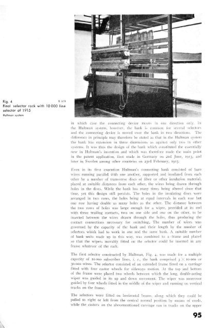
The first selector constructed by Hultman, Fig. 4, was made for a multiple<br />
capacity <strong>of</strong> 10 000 subscriber lines, i. c, the bank comprised 3X10000 or<br />
30 000 wires. The selector consisted <strong>of</strong> an extended frame fixed on a carriage<br />
fitted with four castor wheels for sideways motion. At the top and bottom<br />
<strong>of</strong> the frame were placed two wheels between which the long, double-acting<br />
wiper was guided in its up and down movement. The wiper was moreover<br />
guided by four wheels fitted in the middle <strong>of</strong> the wiper and running on vertical<br />
tracks on the frame.<br />
The selectors were fitted on horizontal beams, along which they could be<br />
pulled to right or left from the central normal position by means <strong>of</strong> cords,<br />
while the castors on the abovementioned carriage ran in tracks on the upper<br />
95


