Renold Couplings Cat 7th-4 - Industrial and Bearing Supplies
Renold Couplings Cat 7th-4 - Industrial and Bearing Supplies
Renold Couplings Cat 7th-4 - Industrial and Bearing Supplies

Create successful ePaper yourself
Turn your PDF publications into a flip-book with our unique Google optimized e-Paper software.
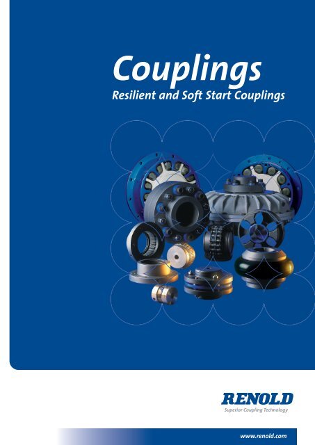
<strong>Couplings</strong><br />
Resilient <strong>and</strong> Soft Start <strong>Couplings</strong><br />
Superior Coupling Technology<br />
www.renold.com
Clutches & <strong>Couplings</strong><br />
Wentloog Corporate Park, Newl<strong>and</strong>s Road, Cardiff CF3 2EU<br />
Wales<br />
Tel: +44 (0) 29 20792737<br />
Fax: +44 (0) 29 20793004<br />
(Sales): +44 (0) 29 20791360<br />
E-Mail: couplings@cc.renold.com<br />
couplings@renold.com<br />
clutches@renold.com<br />
cardiff.sales@renold.co.uk<br />
Web: www.renold.com<br />
Products:<br />
Shaft <strong>Couplings</strong>, Resilient Gear <strong>and</strong> Fluid Soft-Start,<br />
Clutches: Sprag <strong>and</strong> Trapped Roller Freewheels,<br />
Slipping <strong>and</strong> Air Types.<br />
For more information telephone us on +44 (0) 29 20792737 or fax +44 (0) 29 20791360 E-Mail: cardiff.sales@renold.com
Contents<br />
Company Profile 5<br />
Typical Applications 6 - 7<br />
Pictorial Contents 8 - 9<br />
Coupling Selection Guide 10<br />
Selections 12 - 15<br />
Taper Bushes 15<br />
Spiderflex 16 - 18<br />
Spider 19<br />
Pinflex 20 - 24<br />
Crownpin 25 - 27<br />
Tyreflex 28 - 30<br />
Discflex 31 - 33<br />
Chainflex 34 - 35<br />
Rigid 36<br />
Gearflex 37 - 46<br />
Hydrastart 47 - 60<br />
Electric Motor Shaft Dimensions 54<br />
<strong>Renold</strong> Hi-Tec Coupling Range 61 - 91<br />
<strong>Renold</strong> Worldwide Sales & Services 94 - 95<br />
For more information telephone us on +44 (0) 29 20792737 or fax +44 (0) 29 20791360 E-Mail: cardiff.sales@renold.com<br />
3<br />
Page No
WHEN IT COMES<br />
TO AVAILABILITY,<br />
WOULD RIGHT AWAY<br />
BE SOON ENOUGH?<br />
The Power Transmission Solution<br />
RENOLD CLUTCHES & COUPLINGS<br />
Wentloog Corporate Park Newl<strong>and</strong>s Road Cardiff CF3 2EU<br />
Telephone: + 44 (0) 29 20792737 Fax: + 44 (0) 29 20791360 http://www.renold.com<br />
4<br />
Did you know <strong>Renold</strong> make the widest range<br />
of couplings? Stocked by all major<br />
distributors, over 300 outlets throughout the<br />
country. Manufactured in the UK to <strong>Renold</strong>’s<br />
stringent specifications it’s never too soon to<br />
get your h<strong>and</strong>s on the UK’s most available<br />
range of couplings.<br />
FLEXIBLE COUPLINGS<br />
SPRAG CLUTCHES<br />
WORM GEARS<br />
HELICAL GEARS<br />
BEVEL HELICAL<br />
GEARS<br />
VARIABLE SPEED<br />
INDEXERS
<strong>Renold</strong> Clutches & <strong>Couplings</strong><br />
<strong>Renold</strong> have been manufacturing flexible <strong>and</strong> rigid couplings, sprag <strong>and</strong> air clutches for over 50 years. The <strong>Renold</strong> <strong>Couplings</strong> factories are<br />
based in two UK locations, Cardiff <strong>and</strong> Halifax.<br />
Clutches & <strong>Couplings</strong> - Cardiff<br />
In 1991 the company moved to a purpose-built factory in<br />
Wentloog, Cardiff, in which state-of-the-art machining <strong>and</strong><br />
inspection facilities are to be found, all supporting a high level of<br />
personal customer care.<br />
Service Excellence & Care<br />
Hi-Tec <strong>Couplings</strong> - Halifax<br />
The Halifax factory (formally Holset Engineering Ltd.) became a<br />
member of <strong>Renold</strong> plc in 1996. The operation also includes the<br />
latest machining <strong>and</strong> tooling technology with integrated cellular<br />
manufacturing <strong>and</strong> complete<br />
testing <strong>and</strong> balancing<br />
capabilities.<br />
All <strong>Renold</strong> <strong>Couplings</strong> are<br />
manufactured in the UK to<br />
<strong>Renold</strong> exacting st<strong>and</strong>ards.<br />
<strong>Renold</strong> offers a unique level of service excellence <strong>and</strong> customer<br />
care. Our experienced applications engineers will select the<br />
optimum solution, with the aid of the latest computer <strong>and</strong> design<br />
technology.<br />
The organisation stretches worldwide<br />
• 16 National Sales Companies<br />
• Over 70 Overseas Distributors<br />
5<br />
Special Solutions <strong>and</strong> Innovations<br />
<strong>Renold</strong> is recognised throughout the industry for its capability to<br />
create specific solutions to customers unique requirements.<br />
International companies <strong>and</strong> industries, from steel to food<br />
processing to escalators to textile machinery, have chosen <strong>Renold</strong> to<br />
solve their problems.<br />
Consistent Reliability<br />
<strong>Renold</strong>’s 100 years of experience in the design <strong>and</strong> manufacturing<br />
of power transmission products to the highest specifications, with<br />
proven performance in diverse industries world-wide, underwrites<br />
the guaranteed quality <strong>and</strong> the assurance of reliability.<br />
<strong>Renold</strong> Clutches & <strong>Couplings</strong> is BS EN ISO 9001:2000 approved.<br />
All products are designed <strong>and</strong> manufactured to this<br />
Quality Assurance System.<br />
Testing<br />
LRQO/881495<br />
Leading Edge Technology<br />
<strong>Renold</strong> provides practical cost<br />
effective solutions with a<br />
commitment to value through<br />
quality. This is achieved by the<br />
continuous investment in people,<br />
process technology <strong>and</strong><br />
manufacturing.<br />
Certificate 9079<br />
Although each of our factories manufacturing <strong>and</strong> testing dem<strong>and</strong>s<br />
vary, the following capabilities are available if the application<br />
dem<strong>and</strong>s it:<br />
• Full scale radial <strong>and</strong> axial stiffness measurement.<br />
• Torsional vibration analysis.<br />
• Misalignment testing of couplings up to 2 metres diameter.<br />
• Measurements of torsional stiffness up to 220 KNM<br />
• Static <strong>and</strong> dynamic balancing capabilities.<br />
• Noise attenuation testing.<br />
• Transient <strong>and</strong> finite element analysis.<br />
Offering the comprehensive range of power transmission products directly or through local distributor networks<br />
For more information telephone us on +44 (0) 29 20792737 or fax +44 (0) 29 20791360 E-Mail: cardiff.sales@renold.com
Flexible <strong>and</strong> Soft Start <strong>Couplings</strong> - Typical Applications<br />
Pinflex<br />
A robust general purpose pin/buffer coupling, providing reliable fail<br />
safe transmission of torque <strong>and</strong> misalignment capability.<br />
● Pumps<br />
● Compressors<br />
● Conveyors<br />
Spider <strong>Couplings</strong><br />
Relatively low power but highly flexible coupling with halfbodies in<br />
either cast iron or bronze, making suitable for use in the food or<br />
chemical/pharmaceutical industries.<br />
● Pumps<br />
● Mixers<br />
● Lube Systems<br />
▲<br />
▲<br />
▲<br />
▲<br />
▲<br />
For more information telephone us on +44 (0) 29 20792737 or fax +44 (0) 29 20791360 E-Mail: cardiff.sales@renold.com<br />
6<br />
Hydrastart<br />
A fluid coupling suitable for soft starting high inertia machinery<br />
with reduced current dem<strong>and</strong>, controlled acceleration <strong>and</strong> torque<br />
with drive overload protection.<br />
● Conveyors<br />
● Rotary Kilns<br />
● Ball Mills<br />
Crown Pin<br />
An established pin/buffer coupling offering extended power<br />
capacity where the dem<strong>and</strong> for long life <strong>and</strong> simplicity of<br />
construction make it suitable for working in arduous conditions.<br />
● Conveyors<br />
● Washers<br />
● Pumps<br />
Gearflex<br />
● Fans<br />
● Centrifuges<br />
● Screens<br />
● Cranes<br />
● General <strong>Industrial</strong> Application<br />
Heavy duty all metal couplings giving maximum power capacity<br />
within minimum space envelope <strong>and</strong> excellent misalignment<br />
capacity.<br />
● Steelworks<br />
● Quarries<br />
● Mining
Flexible <strong>and</strong> Soft Start <strong>Couplings</strong> - Typical Applications<br />
Discflex<br />
A general purpose, fail safe, torsionally flexible coupling offering<br />
the option of either urethane or reinforced rubber disc.<br />
● Pumps<br />
● Compressors<br />
Tyreflex<br />
A range of highly flexible couplings offering excellent misalignment<br />
capacity <strong>and</strong> suitable to absorb both shock loads <strong>and</strong> vibrations.<br />
● Pumps<br />
● Compressors<br />
PM<br />
● Conveyors<br />
● Mixers<br />
● Diesel Engines<br />
● Roller Tables<br />
2 off PM600 on a nickel grinding mill at Leinster in Western Australia.<br />
● Metal Manufacturing<br />
● Pumps<br />
● Fans<br />
● Compressors<br />
● Pulp <strong>and</strong> Paper<br />
● Cranes <strong>and</strong> hoists<br />
▲<br />
▲<br />
▲<br />
▲<br />
▲<br />
For more information telephone us on +44 (0) 29 20792737 or fax +44 (0) 29 20791360 E-Mail: cardiff.sales@renold.com<br />
7<br />
Spiderflex<br />
A medium powered, torsionally flexible coupling, combining shock<br />
absorbing <strong>and</strong> misalignment. Used in the widest range of industries<br />
<strong>and</strong> applications.<br />
RB<br />
0.24 RB flywheel mounted coupling on a Deutz TD 229 - 6 diesel<br />
generator set in Spain.<br />
● Generator Sets<br />
● Pump Sets<br />
● Compressors<br />
● Bulk H<strong>and</strong>ling
Spiderflex Coupling<br />
The Interchangeable & Cost Effective Solution<br />
A medium powered torsionally flexible coupling, combining shock<br />
absorbing <strong>and</strong> misalignment capacity. Used in the widest range of<br />
industries <strong>and</strong> applications.<br />
Max Kw @ 100 rpm: 35<br />
Max Torque: 3308 Nm<br />
Page No 17<br />
The Popular Choice<br />
A robust general purpose pin/buffer coupling, providing reliable fail<br />
safe transmission of torque <strong>and</strong> misalignment capability.<br />
Max Kw @ 100 rpm: 340<br />
Max Torque: 32500 Nm<br />
Page No 21<br />
Pictorial Contents<br />
For more information telephone us on +44 (0) 29 20792737 or fax +44 (0) 29 20791360 E-Mail: cardiff.sales@renold.com<br />
8<br />
Spider Coupling<br />
The Cost Effective Solution<br />
Small powered, torsionally flexible coupling with shock absorbing<br />
<strong>and</strong> misalignment capacity.<br />
Max Kw @ 100 rpm: 1.12<br />
Max Torque: 107 Nm<br />
Page No 20<br />
Pinflex Coupling Crownpin Flexible Coupling<br />
The Reliable Solution<br />
Tyreflex Coupling Discflex Coupling<br />
The Interchangeable Resilient Solution<br />
A range of highly flexible couplings offering excellent misalignment<br />
capacity <strong>and</strong> suitable to absorb both shock loads <strong>and</strong> vibrations.<br />
Max Kw @ 100 rpm: 65.8<br />
Max Torque: 6270 Nm<br />
Page No 29<br />
An established pin/buffer coupling, offering extended power<br />
capacity where the dem<strong>and</strong> for long life <strong>and</strong> simplicity of<br />
construction make it suitable for working in arduous conditions.<br />
Max Kw @ 100 rpm: 2611<br />
Max Torque: 249400 Nm<br />
Page No 26<br />
The Positive Solution<br />
A general purpose, fail safe, torsionally flexible coupling offering<br />
the option of either urethane or reinforced rubber disc as the<br />
flexible element.<br />
Max Kw @ 100 rpm: 45<br />
Max Torque: 4298 Nm<br />
Page No 33
Pictorial Contents<br />
Chainflex Coupling Rigid Coupling<br />
The Flexible Solution<br />
An all metal flexible yet torsionally stiff coupling, suitable for use in<br />
arduous working conditions.<br />
Max Kw @ 100 rpm: 90<br />
Max Torque: 8595 Nm<br />
Page No 36<br />
Taper Bushes<br />
The Easy Maintenance Solution<br />
Max Bore Size: 125mm<br />
Page No 16<br />
Hydrastart St<strong>and</strong>ard Fill<br />
The Soft Start Solution<br />
A fluid coupling suitable for soft starting high inertia machinery<br />
with reduced current dem<strong>and</strong>, controlled acceleration <strong>and</strong> torque<br />
with drive overload protection.<br />
Max Kw @ 1500 rpm: 600<br />
Max Speed: 3,500 rpm<br />
Page No 49<br />
For more information telephone us on +44 (0) 29 20792737 or fax +44 (0) 29 20791360 E-Mail: cardiff.sales@renold.com<br />
9<br />
The Rigid Solution<br />
Rigid all metal medium/high power coupling for a non-flexible,<br />
positive connection.<br />
Max Bore Size: 290 mm<br />
Page No 38<br />
Gearflex Coupling - Double Engagement<br />
The High Torque Solution<br />
Heavy duty all metal couplings giving maximum power capacity<br />
within minimum space envelope <strong>and</strong> excellent misalignment<br />
capacity.<br />
Max Kw @ 100 rpm: 50485<br />
Max Torque: 4747000 Nm<br />
Page No 39<br />
RB & PM <strong>Couplings</strong><br />
The Heavy Duty Solution<br />
Max Torque 6000KNm<br />
Page No’s 64 <strong>and</strong> 76
Drive Power<br />
Low up to 10kW<br />
Medium Power up to 50kW<br />
High Power over 50kW<br />
YES<br />
YES<br />
YES<br />
Coupling Selection Guide<br />
High Speed<br />
(Motor Speeds)<br />
YES<br />
Torsionally<br />
Flexible<br />
Spider<br />
Discflex<br />
Pinflex<br />
YES<br />
High Speed<br />
(Motor Speeds)<br />
YES<br />
Torsionally<br />
Flexible<br />
Spider<br />
Discflex<br />
Pinflex<br />
RB<br />
YES<br />
High Speed<br />
(Motor Speeds)<br />
YES<br />
Torsionally<br />
Flexible<br />
YES<br />
Gearflex<br />
Chainflex<br />
RB<br />
PM<br />
NO<br />
Spiderflex<br />
Tyreflex<br />
Crownpin<br />
NO<br />
Spiderflex<br />
Tyreflex<br />
Crownpin<br />
PM<br />
NO<br />
NO<br />
NO<br />
NO<br />
For more information telephone us on +44 (0) 29 20792737 or fax +44 (0) 29 20791360 E-Mail: cardiff.sales@renold.com<br />
10<br />
Gearflex<br />
Chainflex<br />
Flex<br />
Gearflex<br />
Chainflex<br />
Flex<br />
Gearflex<br />
Chainflex<br />
Torsionally<br />
Flexible<br />
Torsionally<br />
Flexible<br />
Torsionally<br />
Flexible<br />
YES<br />
YES<br />
YES<br />
NO<br />
NO<br />
NO<br />
Spider<br />
Discflex<br />
Pinflex<br />
Spider<br />
Discflex<br />
Pinflex<br />
RB<br />
Pinflex<br />
Crownpin<br />
RB<br />
PM<br />
Gearflex<br />
Chainflex<br />
Flex<br />
Spiderflex<br />
Tyreflex<br />
Crownpin<br />
Gearflex<br />
Chainflex<br />
Flex<br />
Spiderflex<br />
Tyreflex<br />
Crownpin<br />
PM<br />
Gearflex<br />
Chainflex
Flexible <strong>Couplings</strong> should be used to accommodate any combination of<br />
misalignment conditions described below.<br />
At installation all couplings should be aligned as near to perfect<br />
as possible.<br />
1. Angular<br />
Angular misalignment is present when the shaft axes are inclined<br />
one to the other. Its magnitude can be measured at the coupling<br />
faces.<br />
2. Parallel Offset<br />
O<br />
Ø<br />
Axial misalignment is present when the axes of the driving <strong>and</strong><br />
driven shafts are parallel but laterally displaced.<br />
3. End float (axial)<br />
End float is the ability to accommodate a relative axial displacement<br />
of the connected shafts; achieved by sliding members or flexing of<br />
resilient components.<br />
4. Torsional flexibility<br />
ƒ<br />
Torsional flexibility is a design feature necessary to permit shock<br />
<strong>and</strong> impulsive loadings to be suitably dampened. It is achieved by<br />
the provision of a flexible medium such as rubber, springs, etc.,<br />
between the two halves of the coupling.<br />
Selection of <strong>Couplings</strong><br />
Ø<br />
For more information telephone us on +44 (0) 29 20792737 or fax +44 (0) 29 20791360 E-Mail: cardiff.sales@renold.com<br />
11<br />
Selection<br />
In order to select the correct type <strong>and</strong> size of coupling, the<br />
following basic information should be known:<br />
Power to be transmitted<br />
(a) Normal.<br />
(b) Maximum.<br />
(c) Whether continuous or intermittent.<br />
Characteristics of the drive<br />
(a) Type of prime mover <strong>and</strong> associated equipment.<br />
(b) Degree of impulsiveness of driven load.<br />
Speed in revolutions per minute<br />
(a) At which normal power is transmitted.<br />
(b) At which maximum power is transmitted.<br />
(c) Maximum speed.<br />
Dimensions of shafts to be connected<br />
(a) Actual diameter.<br />
(b) Length of shaft extension.<br />
(c) Full keyway particulars.<br />
Selection<br />
When the input drive is not steady (i.e. not from an electric motor),<br />
<strong>and</strong>/or the driven load is impulsive, the actual power is multiplied<br />
by a Service Factor from the Table 2 (page 13).<br />
Selection Procedure<br />
1. Nominal power in kW to be transmitted = K.<br />
2. Select appropriate load classification from Table 1, denoted as<br />
either S, M or H.<br />
3. From Table 2, establish Service Factor(s) to be applied, taking<br />
into account hours of operation/day <strong>and</strong> prime mover = fD.<br />
4. From Table 3 select factor for the required frequency of<br />
starts/hr = fS.<br />
5. Selection Power Ks = K x fD x fS<br />
6. Equivalent power at 100 RPM =<br />
Ks x 100<br />
RPM<br />
7. Check that coupling selected will accept the required shaft<br />
diameters. Should shaft diameter exceed maximum<br />
permissible, then re-select using next larger size of coupling.
Table 1<br />
Agitators<br />
Pure liquids S<br />
Liquids <strong>and</strong> solids M<br />
Liquids-variable density<br />
Blowers<br />
M<br />
Centrifugal S<br />
Lobe M<br />
Vane<br />
Brewing <strong>and</strong> Distilling<br />
S<br />
Bottling machinery S<br />
Brew kettles-continuous duty S<br />
Cookers-continuous duty S<br />
Mash tubs-continuous duty S<br />
Scale hopper-frequent starts M<br />
Can filling machines S<br />
Cane knives (1) M<br />
Car dumpers H<br />
Car pullers M<br />
Clarifiers S<br />
Classifiers<br />
Clay working machinery<br />
M<br />
Brick press H<br />
Briquette machine H<br />
Clay working machinery M<br />
Pug mill<br />
Compressors<br />
M<br />
Centrifugal S<br />
Lobe M<br />
Reciprocating - multi-cylinder M<br />
Reciprocating - single cylinder H<br />
Conveyors - uniformly loaded or fed<br />
Apron S<br />
Assembly S<br />
Belt S<br />
Bucket S<br />
Chain S<br />
Flight S<br />
Oven S<br />
Screw<br />
Conveyors - heavy duty<br />
not uniformly fed<br />
S<br />
Apron M<br />
Assembly M<br />
Belt M<br />
Bucket M<br />
Chain M<br />
Flight M<br />
Live roll *<br />
Oven M<br />
Reciprocating H<br />
Screw M<br />
Shaker<br />
Crane Drives - not dry dock<br />
H<br />
Main hoists S<br />
Bridge travel *<br />
Trolley travel<br />
Crushers<br />
*<br />
Ore H<br />
Stone H<br />
Sugar (1)<br />
Dredges<br />
M<br />
Cable reels M<br />
Conveyors M<br />
Cutter head drives H<br />
Jig drives H<br />
Manoeuvring winches M<br />
Pumps M<br />
Screen drive H<br />
Stackers M<br />
Utility winches<br />
Dry dock cranes<br />
M<br />
Main hoist (2)<br />
S = Steady<br />
M = Medium Impulsive<br />
H = Highly Impulsive<br />
* = Refer to <strong>Renold</strong><br />
Load Classification by Application<br />
(1) = Select on 24 hours per day service factor only.<br />
Auxiliary hoist (2)<br />
Boom, luffing (2)<br />
Rotating, swing or slew (3)<br />
Tracking, drive wheels<br />
Elevators<br />
(4)<br />
Bucket - uniform load S<br />
Bucket - heavy load M<br />
Bucket - continuous S<br />
Centrifugal discharge S<br />
Escalators S<br />
Freight M<br />
Gravity discharge S<br />
Man lifts *<br />
Passenger<br />
Extruders (plastic)<br />
*<br />
Film S<br />
Sheet S<br />
Coating S<br />
Rods S<br />
Tubing S<br />
Blow moulders M<br />
Pre-plasticiers<br />
Fans<br />
M<br />
Centrifugal<br />
Cooling towers<br />
S<br />
Induced draft *<br />
Forced draft *<br />
Induced draft M<br />
Large, mine etc. M<br />
Large, industrial M<br />
Light, small diameter<br />
Feeders<br />
S<br />
Apron M<br />
Belt M<br />
Disc S<br />
Reciprocating H<br />
Screw<br />
Food industry<br />
M<br />
Beef slicer M<br />
Cereal cooker S<br />
Dough mixer M<br />
Meat grinder M<br />
Generators - not welding S<br />
Hammer mills<br />
Hoists<br />
H<br />
Heavy duty H<br />
Medium duty M<br />
Skip hoist<br />
Laundry<br />
M<br />
Washers - reversing M<br />
Tumblers<br />
Line shafts<br />
M<br />
Driving processing equipment M<br />
Light S<br />
Other line shafts<br />
Lumber industry<br />
S<br />
Barkers, hydraulic, mechanical M<br />
Burner conveyor M<br />
Chain saw <strong>and</strong> drag saw H<br />
Chain transfer H<br />
Craneway transfer H<br />
De-barking drum H<br />
Edger feed M<br />
Gang feed M<br />
Green chain M<br />
Live rolls H<br />
Log deck H<br />
Log haul-incline H<br />
Log haul-well type H<br />
Log turning device H<br />
Main log conveyor H<br />
Off bearing rolls M<br />
Planer feed chains M<br />
(2) = Use service factor of 1.00 for any duration of service.<br />
(3) = Use service factor of 1.25 for any duration of service.<br />
(4) = Use service factor of 1.50 for any duration of service.<br />
For more information telephone us on +44 (0) 29 20792737 or fax +44 (0) 29 20791360 E-Mail: cardiff.sales@renold.com<br />
12<br />
Planer floor chains M<br />
Planer tilting hoist M<br />
Re-saw merry-go-round conveyor M<br />
Roll cases H<br />
Slab conveyor H<br />
Small waste conveyor-belt S<br />
Small waste conveyor-chain M<br />
Sorting table M<br />
Tipple hoist conveyor M<br />
Tipple hoist drive M<br />
Transfer conveyors M<br />
Transfer rolls M<br />
Tray drive M<br />
Trimmer feed M<br />
Waste conveyor<br />
Machine tools<br />
M<br />
Bending roll M<br />
Punch press-gear driven H<br />
Notching press-belt drive *<br />
Plate planners H<br />
Tapping machine<br />
Other machine tools<br />
H<br />
Main drives M<br />
Auxiliary drives<br />
Metal mills<br />
Drawn bench carriage<br />
S<br />
<strong>and</strong> main drive<br />
Pinch, dryer <strong>and</strong> scrubber<br />
M<br />
rolls, reversing *<br />
Slitters<br />
Table conveyors non-<br />
M<br />
reversing group drives M<br />
Individual drives H<br />
Reversing *<br />
Wire drawing <strong>and</strong> flattening machineM<br />
Wire winding machine<br />
Mills, rotary type<br />
M<br />
Ball (1) M<br />
Cement kilns (1) M<br />
Dryers <strong>and</strong> coolers (1) M<br />
Kilns other than cement M<br />
Pebble (1) M<br />
Rod, plain & wedge bar (1) M<br />
Tumbling barrels<br />
Mixers<br />
H<br />
Concrete mixers continuous M<br />
Concrete mixers intermittent M<br />
Constant density S<br />
Variable density<br />
Oil industry<br />
M<br />
Chillers M<br />
Oil well pumping *<br />
Paraffin filter press M<br />
Rotary kilns M<br />
Paper mills<br />
Agitators (mixers) M<br />
Barker-auxiliaries hydraulic M<br />
Barker-mechanical H<br />
Barking drum H<br />
Beater <strong>and</strong> pulper M<br />
Bleacher S<br />
Calenders M<br />
Calenders-super<br />
Converting machine except<br />
H<br />
cutters, platers M<br />
Conveyors S<br />
Couch M<br />
Cutters, platers H<br />
Cylinders M<br />
Dryers M<br />
Fell stretcher M<br />
Fell whipper H<br />
Jordans M<br />
Log haul H<br />
Presses M<br />
Pulp machine reel M<br />
Stock chest M<br />
Note<br />
Suction roll M<br />
Washers <strong>and</strong> thickeners M<br />
Winders M<br />
Printing presses<br />
Pullers<br />
*<br />
Barge haul<br />
Pumps<br />
H<br />
Centrifugal S<br />
Proportioning<br />
Reciprocating<br />
single acting:<br />
M<br />
3 or more cylinders<br />
double acting:<br />
M<br />
2 or more cylinders M<br />
single acting: 1 or 2 cylinders *<br />
double acting: single cylinder *<br />
Rotary - gear type S<br />
Rotary - lobe, vane<br />
Rubber <strong>and</strong> plastics industries<br />
S<br />
Crackers (1) H<br />
Laboratory equipment M<br />
Mixed mills (1) H<br />
Refiners (1) M<br />
Rubber calenders (1) M<br />
Rubber mill, 2 on line (1) M<br />
Rubber mill, 3 on line (1) S<br />
Sheeter (1) M<br />
Tyre building machines *<br />
Tyre <strong>and</strong> tube press openers *<br />
Tubers <strong>and</strong> strainers (1) M<br />
Warming mills (1) M<br />
S<strong>and</strong> muller<br />
Screens<br />
M<br />
Air washing S<br />
Rotary, stone or gravel M<br />
Travelling water intake<br />
Sewage disposal equipment<br />
S<br />
Bar screens S<br />
Chemical feeders S<br />
Collectors S<br />
Dewatering screws M<br />
Scum breakers M<br />
Slow or rapid mixers M<br />
Thickeners M<br />
Vacuum filters M<br />
Slab pushers M<br />
Steering gear *<br />
Stokers<br />
Sugar industry<br />
S<br />
Cane knives (1) M<br />
Crushers (1) M<br />
Mills (1)<br />
Textile industry<br />
M<br />
Batchers M<br />
Calenders M<br />
Cards M<br />
Dry cans M<br />
Dryers M<br />
Dyeing machinery M<br />
Looms M<br />
Mangles M<br />
Nappers M<br />
Pads M<br />
Range drives *<br />
Slashers M<br />
Soapers M<br />
Spinners M<br />
Tenter frames M<br />
Washers M<br />
Winders M<br />
Windlass *<br />
Machinery characteristics <strong>and</strong> service factors listed in this catalogue<br />
are a guide only. Some applications (e.g. constant power) may<br />
require special considerations. Consult <strong>Renold</strong>.
Service Factors <strong>and</strong> Selection<br />
Service Factors<br />
Table 2 Service Factor (fD ) Table 3 Factor for Starts/hour (fS )<br />
Driven machinery characteristics<br />
Prime mover Duration Steady Medium Highly<br />
(Drive input) Service load impulsive impulsive<br />
hours/day<br />
Electric, Air & Intermittent-<br />
Hydraulic Motors 3hrs/day max 0.90 1.00 1.50<br />
or Steam Turbine 3 - 10 1.00 1.25 1.75<br />
(Steady input) over 10 1.25 1.50 2.00<br />
Multi-cylinder I.C. Intermittentengine<br />
(Medium 3hrs/day max 1.00 1.25 1.75<br />
impulsive input) 3 - 10 1.25 1.50 2.00<br />
over 10 1.50 1.75 2.25<br />
Single-cylinder Intermittent-<br />
I.C. engine 3hrs/day max 1.25 1.50 2.00<br />
(Highly impulsive 3 - 10 1.50 1.75 2.25<br />
input) over 10 1.75 2.00 2.50<br />
Example Of Selection<br />
Coupling is required to transmit 7.5kW at 1440 RPM to connect an<br />
electric motor to a gear box driving a chain conveyor running for 18<br />
hours/day <strong>and</strong> starting 15 times/hour. Shaft diameters /55mm<br />
respectively.<br />
K = 7.5kW<br />
From Table 1 Load Classification = M (medium impulsive)<br />
From Table 2 Service Factor f D = 1.5<br />
From Table 3 f S = 1.2<br />
Therefore selection kW is:-<br />
Ks = K x fD x fS = 7.5 x 1.5 x 1.2<br />
= 13.5 kW<br />
Equivalent power at 100RPM =<br />
=<br />
Ks x 100<br />
RPM<br />
13.5 x 100<br />
1440<br />
= 0.9375kW @ 100RPM<br />
From page 16 selection is RSC110 (644911) (maximum bore 55 mm).<br />
For more information telephone us on +44 (0) 29 20792737 or fax +44 (0) 29 20791360 E-Mail: cardiff.sales@renold.com<br />
13<br />
No of Starts<br />
Per Hour<br />
0-1 1-30 30-60 60-<br />
Factor 1,0 1,2 1,3 1,5<br />
Note<br />
For applications with excessive vibration, contact <strong>Renold</strong> Technical<br />
Department.<br />
Key Stress<br />
1. Permissible key stress = 70N/mm 2<br />
2. Nominal torque TKM = k x 9550 / RPM Nm<br />
3. Force at key F = TKM /r<br />
4. Shaft Rad r. metres<br />
5. Key area A = J x HUB length mm (Obtain from relevant<br />
catalogue page).<br />
6. Key stress fk = F/A N/mm 2<br />
7. If resultant stress is less than 70 N/mm 2<br />
Key stress is acceptable.<br />
If resultant fk is greater than 70, consider either two keyways<br />
or extending hub length.<br />
8. Example:<br />
TKM = 7.5 x 9550/1440 = 49.7Nm<br />
r = 55/2 = 27.5mm ÷ 1000 = 0.0275M<br />
F = 49.7/0.0275 = 1741N<br />
A = 16 x 45 = 720mm 2<br />
fk = 1741/720 = 2.4M/mm 2<br />
Selection is therefore good.<br />
For operation above 80% of the declared maximum coupling speed it is recommended that the coupling is dynamically balanced.<br />
It is the responsibility of the system<br />
designer to ensure that the application of<br />
the coupling does not endanger the other<br />
constituent components in the system.<br />
Service factors given are an initial<br />
selection guide.<br />
Rotating equipment must be provided<br />
with a suitable guard before operating or<br />
injury may result.
Keyway dimensions<br />
K<br />
Parallel keyways are supplied unless customer states otherwise.<br />
Key <strong>and</strong> Keyway Dimensions<br />
J<br />
L<br />
For more information telephone us on +44 (0) 29 20792737 or fax +44 (0) 29 20791360 E-Mail: cardiff.sales@renold.com<br />
14<br />
Metric (mm)<br />
Keyways comply with BS4235: Part 1: 1972<br />
Over<br />
6<br />
8<br />
10<br />
12<br />
17<br />
22<br />
30<br />
38<br />
44<br />
50<br />
58<br />
65<br />
75<br />
85<br />
95<br />
110<br />
130<br />
150<br />
170<br />
200<br />
Shaft dia.<br />
Incl. J K L<br />
8<br />
10<br />
12<br />
17<br />
22<br />
30<br />
38<br />
44<br />
50<br />
58<br />
65<br />
75<br />
85<br />
95<br />
110<br />
130<br />
150<br />
170<br />
200<br />
230<br />
Imperial (inches)<br />
2<br />
3<br />
4<br />
5<br />
6<br />
8<br />
10<br />
12<br />
14<br />
16<br />
18<br />
20<br />
22<br />
25<br />
28<br />
32<br />
36<br />
40<br />
45<br />
50<br />
Keyways comply with BS46: Part 1: 1958<br />
Over<br />
0.25<br />
0.50<br />
0.75<br />
1.00<br />
1.25<br />
1.50<br />
1.75<br />
2.00<br />
2.50<br />
3.00<br />
3.50<br />
4.00<br />
5.00<br />
Shaft dia.<br />
0.50<br />
0.75<br />
1.00<br />
1.25<br />
1.50<br />
1.75<br />
2.00<br />
2.50<br />
3.00<br />
3.50<br />
4.00<br />
5.00<br />
6.00<br />
0.125<br />
0.187<br />
0.250<br />
0.312<br />
0.375<br />
0.437<br />
0.500<br />
0.625<br />
0.750<br />
0.875<br />
1.000<br />
1.250<br />
1.500<br />
Key & Keyway<br />
2<br />
3<br />
4<br />
5<br />
6<br />
7<br />
8<br />
8<br />
9<br />
10<br />
11<br />
12<br />
14<br />
14<br />
16<br />
18<br />
20<br />
22<br />
25<br />
28<br />
Key & Keyway<br />
1.0<br />
1.4<br />
1.8<br />
2.3<br />
2.8<br />
3.3<br />
3.3<br />
3.3<br />
3.8<br />
4.3<br />
4.4<br />
4.9<br />
5.4<br />
5.4<br />
6.4<br />
7.4<br />
8.4<br />
9.4<br />
10.4<br />
11.4<br />
Incl. J K L<br />
0.125<br />
0.187<br />
0.250<br />
0.250<br />
0.250<br />
0.312<br />
0.312<br />
0.437<br />
0.500<br />
0.625<br />
0.750<br />
0.875<br />
1.000<br />
0.060<br />
0.088<br />
0.115<br />
0.090<br />
0.085<br />
0.112<br />
0.108<br />
0.162<br />
0.185<br />
0.245<br />
0.293<br />
0.340<br />
0.384
Metric Range<br />
Range of Taper Bushes<br />
Bush No. Range of Bores (mm)<br />
TB 1008 9 10 - 12 14 16 18 19 20 22 24* 25*<br />
TB 1108 9 10 11 12 14 15 16 18 19 20 22 24 25 28*<br />
TB 1210 11 12 14 16 18 19 20 22 24 25 28* 30* 32*<br />
TB 1215 11 12 14 16 18 19 20 22 24 25 28 30 32*<br />
TB 1610 14 16 18 19 20 22 24 25 28 30 32 35 38 40 42<br />
TB 1615 14 16 18 19 20 22 24 25 28 30 32 35 38 40* 42*<br />
TB 2012 14 16 18 19 20 22 24 25 28 30 32 35 38 40 42 44 45 48 50<br />
TB 2017 18 19 20 22 24 25 28 30 32 35 38 40 42 45 48 50*<br />
TB 2517 16 18 19 20 22 24 25 28 30 32 35 38 40 42 45 48 50 55 60<br />
TB 2525 19 20 22 24 25 28 30 32 35 38 40 42 45 48 50 55 60<br />
TB 3020 25 28 30 32 35 38 40 42 45 48 50 55 60 65 70 75<br />
TB 3030 35 38 40 42 45 48 50 55 60 65 70 75<br />
TB 3525 35 38 40 42 45 48 50 55 60 65 70 75 80 85 90 95 100*<br />
TB 3535 35 38 40 42 45 48 50 55 60 65 70 75 80 85 90<br />
TB 4030 40 42 45 48 50 55 60 65 70 75 80 85 90 95 100<br />
TB 4040 40 42 45 48 50 55 60 65 70 75 80 85 90 95 100<br />
TB 4535 55 60 65 70 75 80 85 90 95 100 105 110 115 120 125<br />
TB 5050 70 75 80 85 90 95 100 105 110 115 120 125<br />
Imperial Range<br />
Bush No. Range of Bores (inches)<br />
TB1008 0.375 0.437 0.50 0.625 0.75 1.00*<br />
TB 1108 0.375 0.50 0.625 0.75 0.875 1.00 1.125*<br />
TB 1210 - 0.50 - 0.625 - 0.75 - - - 1.00 - - 1.25<br />
TB 1215 - 0.50 0.562 0.625 - 0.75 - 0.875 - 1.00 - - 1.125<br />
TB 1610 0.50 - 0.625 - 0.75 - 0.875 - 1.00 - 1.125 1.25 - - - 1.50 1.625<br />
TB 1615 0.50 - 0.625 - 0.75 - 0.875 - 1.00 - 1.125 1.25 - 1.375 1.437 1.50 1.625*<br />
TB 2012 0.50 0.625 0.75 0.875 1.00 - 1.125 - 1.25 - 1.375 1.50 1.625 1.75 1.87 2.0<br />
TB 2017 0.75 0.812 0.875 0.937 1.00 - 1.125 - 1.25 - 1.375 1.50 1.625 1.75 1.875 2.00<br />
TB 2517 0.75 0.875 - 1.00 - 1.125 - 1.25 - 1.375 1.437 1.625 1.75 1.875 2.00 2.125 2.25 2.375* 2.50<br />
TB 2525 - - 1.00 - 1.125 - 1.25 - 1.375 - 1.50 1.75 1.875 2.00 2.125 2.25 2.375* 2.50*<br />
TB 3020 1.25 - 1.375 - 1.50 1.625 1.75 1.875 2.00 2.125 2.25 2.50 2.625 2.75 2.875 3.00<br />
TB 3030 - - 1.375 - 1.50 1.625 1.75 1.875 2.00 2.125 2.25 2.50 2.625 2.75 2.875 3.00<br />
TB 3525 1.50 1.625 1.75 1.875 2.00 2.125 2.25 2.375 2.50 2.625 2.75 3.00 3.125 3.25 3.50 3.75* 4.00*<br />
TB 3535 1.50 1.625 1.75 1.875 2.00 2.125 2.25 2.375 2.50 2.625 2.75 3.00 3.125 3.25 3.50<br />
TB 4030 1.75 1.875 2.00 2.125 2.25 2.375 2.50 2.625 2.75 2.875 3.00 3.125 3.25 3.375 3.50<br />
TB 4040 1.75 1.875 2.00 2.125 2.25 2.375 2.50 2.625 2.75 2.875 3.00 3.25 3.375 3.50 3.625 3.75* 4.00<br />
TB 4535 2.25 2.375 2.50 2.625 2.75 2.875 3.00 3.125 3.25 3.375 3.50 3.75 4.00 4.25 4.50 4.75 5.00*<br />
TB 5050 2.75 2.875 3.00 3.25 3.375 3.50 3.75 4.00 4.25 4.50 5.00<br />
*Shallow key Depth. N.B.When ordering specify both bush number <strong>and</strong> bore size required.<br />
For more information telephone us on +44 (0) 29 20792737 or fax +44 (0) 29 20791360 E-Mail: cardiff.sales@renold.com<br />
15
Coupling Capacity:<br />
● Maximum power @ 100RPM 33kW<br />
● Maximum torque 3150Nm<br />
Features & Benefits:<br />
● Torsionally flexible - shock absorbing,<br />
extending machine life.<br />
● Maintenance free - minimum number of<br />
wearing parts.<br />
● Misalignment capabilities allowing flexibility<br />
in installation.<br />
● Cost effective - offering a low cost product<br />
with high quality design.<br />
● Dimensionally similar to other spider<br />
couplings - interchangeable.<br />
● Optional fire retardent anti-static elements<br />
for use in flameproof environment.<br />
● Taper bush bores available for ease of<br />
maintenance.<br />
● Compact design - small, with high torque<br />
capacity.<br />
Spiderflex<br />
A medium power torsionally flexible coupling combining shock absorbing <strong>and</strong> misalignment<br />
capacity, used in the widest range of industries <strong>and</strong> applications.<br />
For more information telephone us on +44 (0) 29 20792737 or fax +44 (0) 29 20791360 E-Mail: cardiff.sales@renold.com<br />
16<br />
St<strong>and</strong>ard Range Comprise:<br />
● Shaft to Shaft<br />
● Flywheel to Shaft<br />
● Taper Bush or Parallel Bore<br />
Applications:<br />
● Bulk H<strong>and</strong>ling<br />
● Compressors<br />
● Generator Sets<br />
● Metal Manufacture<br />
● Pumps<br />
● General <strong>Industrial</strong> Applications<br />
Construction Details:<br />
Cast Iron Half Bodies Grade G220<br />
St<strong>and</strong>ard Element Shore Harness A90<br />
Temp Range -30 + 100ºC<br />
F.R.A.S. Element Shore Harness A78<br />
Temp Range -30 + 95ºC<br />
Spiderflex - The Interchangeable Cost Effective Solution
H1<br />
C1<br />
H2<br />
Spiderflex<br />
D B<br />
D B<br />
D B<br />
E<br />
C2<br />
H2<br />
C2<br />
Type B Type F Type H Assembled overall length<br />
Coupling Power Torque Speed Type B Type F & H Max. Misalignment End<br />
Size /100rpm Nominal Max Bore Dia Bush Bore Offset Angular Float<br />
Kw Nm rpm Max Min Size Max Min mm deg mm<br />
RSC70 # # # 0.33 32 7700 32 0 TB1008 25 9 0.3 0.5 +.2<br />
RSC90 # # # 0.84 80 6300 42 0 TB1108 28 9 0.3 0.5 +.5<br />
RSC110 # # # 1.68 160 5000 55 0 TB1610 42 14 0.3 1 +.6<br />
RSC130 # # # 3.30 315 4100 60 0 TB1610 42 14 0.4 1 +.8<br />
RSC150 # # # 6.28 600 3600 70 0 TB2012 50 14 0.4 1.5 +.9<br />
RSC180 # # # 9.95 950 3000 80 0 TB2517 60 16 0.4 1.5 +1.1<br />
RSC230 # # # 21 2000 2600 100 48 TB3020 75 25 0.5 2 +1.3<br />
RSC280 # # # 33 3150 2200 115 60 TB3525 90 35 0.5 2.5 +1.7<br />
Coupling Dimensions Assembled Overall Length L<br />
Size B C1 C2 D E F G H1 H2 With Half Body Combinations:mm<br />
mm mm mm mm mm mm mm mm BB FF, FH, HH FB, HB<br />
RSC70 # # # 61 23.5 23.5 69 31 18 25 20 20.0 65 65 65<br />
RSC90 # # # 70 30.0 23.5 85 32 22.5 30.5 26 19.5 83 70 77<br />
RSC110 # # # 100 45.0 26.5 112 45 29 45 37 18.5 119 82 101<br />
RSC130 # # # 105 55.5 26.5 139 50 36 53 47 18.0 147 89 118<br />
RSC150 # # # 115 60.0 33.5 150 62 40 60 50 23.5 160 107 134<br />
RSC180 # # # 125 70.0 46.5 180 77 49 73 58 34.5 189 142 166<br />
RSC230 # # # 155 90.0 52.5 225 99 59.5 85.5 77 39.5 240 164 202<br />
RSC280 # # # 206 105.5 66.5 275 119 74.5 105.5 90 51.0 285 207 246<br />
1. At speeds exceeding allowable maximum speed, consult <strong>Renold</strong>.<br />
For more information telephone us on +44 (0) 29 20792737 or fax +44 (0) 29 20791360 E-Mail: cardiff.sales@renold.com<br />
17<br />
G<br />
Assembled length<br />
2. Both moment of inertia <strong>and</strong> coupling weight have been calculated assuming fitting of taper bush of medium bore size.<br />
3. For information on torsional stiffness, consult <strong>Renold</strong>.<br />
F<br />
L
Ordering Code<br />
Component Spares<br />
Spiderflex<br />
Size Number Mass Type B Type F&H<br />
Kg Kg m2 Kg m2 Coupling Product Coupling Coupling Inertia WR 2<br />
RSC70 644907 1.00 0.00078 0.00085<br />
RSC90 644909 1.17 0.00108 0.00115<br />
RSC110 644911 5.00 0.00344 0.00400<br />
RSC130 644913 5.46 0.00850 0.00780<br />
RSC150 644915 7.11 0.02112 0.01810<br />
RSC180 644918 16.60 0.04820 0.04340<br />
RSC230 644923 26.00 0.14052 0.12068<br />
RSC280 644928 50.00 0.54790 0.44653<br />
Spiderflex<br />
Specials available, e.g. Shear Pin, Extended Boss, Flywheel Flange, Spacer.<br />
Contact <strong>Renold</strong> for details.<br />
Size<br />
Half Body Type<br />
B - Plain Bore<br />
F - Taper Bush<br />
H - Taper Bush<br />
RSC 70 # # #<br />
Spider Product Half Body Product Half Body Product Half Body Product<br />
Flexible Number Unbored Number Taper Bored Number Taper Bored Number<br />
Element Type B Type F Type H<br />
RSC70 EL 644907/2 RSC70 B 644907/1 RSC70 F 644907/177 RSC70 H 644907/188<br />
RSC90 EL 644909/2 RSC90 B 644909/1 RSC90 F 644909/177 RSC90 H 644909/188<br />
RSC110 EL 644911/2 RSC110 B 644911/1 RSC110 F 644911/177 RSC110 H 644911/188<br />
RSC130 EL 644913/2 RSC130 B 644913/1 RSC130 F 644913/177 RSC130 H 644913/188<br />
RSC150 EL 644915/2 RSC150 B 644915/1 RSC150 F 644915/177 RSC150 H 644915/188<br />
RSC180 EL 644918/2 RSC180 B 644918/1 RSC180 F 644918/177 RSC180 H 644918/188<br />
RSC230 EL 644923/2 RSC230 B 644923/1 RSC230 F 644923/177 RSC230 H 644923/188<br />
RSC280 EL 644928/2 RSC280 B 644928/1 RSC280 F 644928/177 RSC280 H 644928/188<br />
For more information telephone us on +44 (0) 29 20792737 or fax +44 (0) 29 20791360 E-Mail: cardiff.sales@renold.com<br />
18<br />
Element Material<br />
S - St<strong>and</strong>ard<br />
X - F.R.A.S.<br />
Half Body Type<br />
B - Plain Bore<br />
F - Taper Bush<br />
H - Taper Bush
Spider<br />
Coupling Power Torque Speed Bore A Stock Dimensions Misalignment End<br />
Number /100rpm<br />
Kw<br />
Nominal<br />
Nm<br />
Max<br />
rpm<br />
Max<br />
mm<br />
Min<br />
mm<br />
Bore<br />
mm<br />
B<br />
mm<br />
C*<br />
mm<br />
D<br />
mm<br />
F<br />
mm<br />
Mass Angular<br />
Max<br />
kg degrees<br />
Offset<br />
Max<br />
mm<br />
Float<br />
mm<br />
S11C 0.025 2.39 11000 14 0 6 28 12 28 8.8 0.12 1º 0.25 0.25<br />
S11B 0.025 2.39 11000 12 0 6 28 12 28 8.8 0.13 1º 0.25 0.25<br />
S15C 0.061 5.83 6500 20 0 12 38 14 38 11.8 0.26 1º 0.25 0.38<br />
S15B 0.061 5.83 6500 20 0 12 38 14 38 11.8 0.27 1º 0.25 0.38<br />
S21C 0.28 26.74 4800 25 0 14 48 21 55 16.2 0.68 1º 0.25 0.51<br />
S21B 0.28 26.74 4800 25 0 N/A 48 21 55 16.2 0.70 1º 0.25 0.51<br />
S30C 0.56 53.5 4800 30 0 19 57 27 78 22.9 1.57 1º 0.25 0.76<br />
S30B 0.56 53.5 4800 30 0 N/A 57 27 78 22.9 1.63 1º 0.25 0.76<br />
S37C 1.12 107 3500 42 0 24 83 36 95 26.2 3.53 1º 0.25 0.89<br />
S37B 1.12 107 3500 42 0 N/A 83 36 95 26.2 3.66 1º 0.25 0.89<br />
Component Spares<br />
D A<br />
B<br />
C C<br />
Coupling Product Product Spider Half Body Half Body<br />
Number Number Number Flexible Pilot Solid Boss<br />
Pilot Bored Unbored Element Bored Unbored<br />
S11C 644801 644821 644851 644826 644846<br />
S11B 644813 644817 644851 644838 644842<br />
S15C 644802 644822 644852 644827 644847<br />
S15B 644814 644818 644852 644839 644843<br />
S21C 644803 644823 644853 644828 644848<br />
S21B 644815 644819 644853 644840 644844<br />
S30C 644804 644824 644854 644829 644849<br />
S30B MTO MTO 644854 MTO MTO<br />
S37C 644805 644825 644855 644830 644850<br />
S37B MTO MTO 644855 MTO MTO<br />
MTO - Made To Order only - please ask for details.<br />
F<br />
For more information telephone us on +44 (0) 29 20792737 or fax +44 (0) 29 20791360 E-Mail: cardiff.sales@renold.com<br />
19<br />
Spider<br />
Size<br />
Ordering Code<br />
S 15 #<br />
Half Body Material<br />
C - Cast Iron<br />
B - Aluminium Bronze<br />
* To avoid fouling spider, shaft length<br />
inside coupling half-body must not<br />
exceed this dimension
Coupling Capacity:<br />
● Maximum power @ 100RPM 340kW<br />
● Maximum torque 32500Nm<br />
Features & Benefits:<br />
● Steel half bodies, strong yet compact.<br />
● Heavy duty pin <strong>and</strong> buffer coupling - for<br />
heavy shock load conditions.<br />
● Torsionally flexible - shock absorbing,<br />
extending machine life.<br />
● Maintenance free - minimum number of<br />
wearing parts.<br />
● Misalignment capabilities allowing flexibility<br />
in installation.<br />
● Steel Half Bodies.<br />
● Polyurethane buffers, reliable/flexible <strong>and</strong><br />
temperature resistant.<br />
● Modular construction - available as coupling,<br />
brakedrum <strong>and</strong> shear pin designs.<br />
● Taper bores available for ease of<br />
maintenance.<br />
Pinflex<br />
A robust, general purpose pin/buffer coupling providing reliable fail safe transmission of torque<br />
<strong>and</strong> misalignment capability.<br />
St<strong>and</strong>ard Range Comprise:<br />
● Shaft to Shaft<br />
● Shear Pin<br />
● Brake Drum/Disc<br />
Applications:<br />
● Conveyors<br />
● Escalators<br />
● Mixers<br />
● Pumps<br />
● General <strong>Industrial</strong> Applications<br />
Construction Details:<br />
Steel Half Bodies<br />
Pinflex - The Popular Choice<br />
Urethane Buffer: Temp Range - 40ºC to + 80ºC<br />
For more information telephone us on +44 (0) 29 20792737 or fax +44 (0) 29 20791360 E-Mail: cardiff.sales@renold.com<br />
20
D<br />
B<br />
E<br />
Pinflex<br />
C1 C2<br />
C2<br />
Type B Type F Type H Assembled Pinflex Coupling<br />
<strong>Cat</strong>alogue Product Power Torque Speed Type B Type F & H Dimensions Type B Type F & H<br />
Number Number /100rpm Nominal Max Bore Bush Bore B C1 C2 D E F Mass* WR2 * Mass* WR2 *<br />
Kw Nm rpm Max Min Size Max Min mm mm mm mm mm mm kg kg m2 kg kg m2 PF1# #3 8001042/3 2.03 194<br />
PF1# #6 8001042/6 4.05 387 6800 50 0 TB1215 32 11 70 44 40 125 20 4 5.2 0.00828 5.0 0.00813<br />
PF1BB9 8001042/9 6.08 581<br />
PF1BB12 8001042/12 8.1 774<br />
PF2# #3 8002050/3 3.59 343<br />
PF2# #6 8002050/6 7.18 685 5900 55 0 TB1615 42 14 80 50 40 145 25 5 8.3 0.01843 7.6 0.01780<br />
PF2BB9 8002050/9 10.76 1028<br />
PF2BB12 8002050/12 14.35 1370<br />
PF3# #3 8003060/3 4.24 405<br />
PF3# #6 8003060/6 8.48 810 5200 72 0 TB2017 50 18 100 60 47 165 25 5 13.8 0.03335 12.1 0.03143<br />
PF3BB9 8003060/9 12.71 1214<br />
PF3BB12 8003060/12 16.96 1620<br />
PF4# #3 8004075/3 8.32 795<br />
PF4# #6 8004075/6 16.65 1590 4400 80 0 TB2525 60 19 113 75 65 195 35 6 22.0 0.08470 20.3 0.08195<br />
PF4BB9 8004075/9 24.97 2384<br />
PF4BB12 8004075/12 33.29 3179<br />
PF5# #4 8005090/4 13.94 1331<br />
PF5# #8 8005090/8 27.88 2662 3600 110 0 TB3030 75 35 150 89 80 235 35 6 37.8 0.19972 35.3 0.19274<br />
PF5# #12 8005090/12 41.82 3994<br />
PF5BB16 8005090/16 55.76 5325<br />
PF6# #3 8006110/3 24.70 2359<br />
PF6# #6 8006110/6 49.40 4717 2900 130 55 TB3535 90 35 180 110 91 290 50 7 73.2 0.61140 65.2 0.58086<br />
PF6# #9 8006110/9 74.10 7076<br />
PF6BB12 8006110/12 98.80 9435<br />
PF7# #4 8007130/4 37.18 3550<br />
PF7# #8 8007130/8 74.35 7100 2600 150 65 TB4040 100 40 210 130 105 320 50 7 103.0 0.99756 88.5 0.92310<br />
PF7# #12 8007130/12 111.53 10650<br />
PF7BB16 8007130/16 148.70 14200<br />
PF8# #4 8008150/4 64.70 6179<br />
PF8# #8 8008150/8 129.40 12357 2200 175 75 TB5050 125 70 245 150 130 380 60 7 168.8 2.33646 154.1 2.22610<br />
PF8# #12 8008150/12 194.10 18536<br />
PF8BB16 8008150/16 258.80 24714<br />
PF9BB4 8009240/4 85.00 8130<br />
PF9BB8 8009240/8 170.00 16255 1700 260 75 N/A N/A N/A 355 220 - 490 60 7 423.0 9.19000 N/A N/A<br />
PF9BB128009240/12 255.00 24385<br />
PF9BB168009240/16 340.00 32500<br />
NOTE: Maximum power <strong>and</strong> torques for taper bore options are limited by the taper bush capacity.<br />
* Values are for couplings with no bore <strong>and</strong> a full set of pin assemblies.<br />
Max angular misalignment 0.25º<br />
Disc Brake Drum version also available - consult <strong>Renold</strong> for details.<br />
Max axial misalignment 0.13mm<br />
For more information telephone us on +44 (0) 29 20792737 or fax +44 (0) 29 20791360 E-Mail: cardiff.sales@renold.com<br />
21<br />
F
Component Spares<br />
Pinflex<br />
Ordering Code PF 3 # # 9<br />
Pinflex<br />
Size<br />
Half Body Type<br />
B - Plain Bore<br />
F - Taper Bush<br />
H - Taper Bush<br />
Coupling Half Body Pilot Bored Half Body F Type Half Body H Type Pin <strong>and</strong> Buffer Set Coupling<br />
Size <strong>Cat</strong>alogue Product <strong>Cat</strong>alogue Product <strong>Cat</strong>alogue Product Product Number Size<br />
Number Number Number Number Number Number Number Per Set<br />
PF1 PF1 B 8001042 PF1 F 8001042/77 PF1 H 8001042/88 800 0008 3 PF1<br />
PF2 PF2 B 8002050 PF2 F 8002050/77 PF2 H 8002050/88 800 0010 3 PF2<br />
PF3 PF3 B 8003060 PF3 F 8003060/77 PF3 H 8003060/88 800 0010 3 PF3<br />
PF4 PF4 B 8004075 PF4 F 8004075/77 PF4 H 8004075/88 800 0012 1 PF4<br />
PF5 PF5 B 8005090 PF5 F 8005090/77 PF5 H 8005090/88 800 0012 1 PF5<br />
PF6 PF6 B 8006110 PF6 F 8006110/77 PF6 H 8006110/88 800 0016 1 PF6<br />
PF7 PF7 B 8007130 PF7 F 8007130/77 PF7 H 8007130/88 800 0016 1 PF7<br />
PF8 PF8 B 8008150 PF8 F 8008150/77 PF8 H 8008150/88 800 0020 1 PF8<br />
PF9 PF9 B 8009240 N/A N/A N/A N/A 800 0020 1 PF9<br />
For more information telephone us on +44 (0) 29 20792737 or fax +44 (0) 29 20791360 E-Mail: cardiff.sales@renold.com<br />
22<br />
No of Pins<br />
Half Body Type<br />
B - Plain Bore<br />
F - Taper Bush<br />
H - Taper Bush
Pinflex Brakedrum <strong>Couplings</strong><br />
G H<br />
D B1 A1<br />
A2 B2 E<br />
C1 C2<br />
F<br />
Coupling Product Power Torque Speed Bore Drum Dimensions<br />
Size Number /100rpm Nominal Max A1 Max A2 Max Dia E Width G Dia E<br />
Kw Nm rpm mm mm mm mm inch<br />
PFBD1 # 8101042 8.1 774 3600 50 45 160 92 6<br />
PFBD2 # 8102050 14.35 1370 2850 55 50 200 105 8<br />
PFBD3 # 8103060 16.96 1620 2300 72 60 250 124 10<br />
PFBD4 # 8104075 33.29 3179 1900 80 75 315 140 12<br />
PFBD5 # 8105090 55.76 5325 1400 110 90 400 184 16<br />
PFBD6 # 8106110 98.8 9435 1400 130 110 400 184 16<br />
PFBD7 # 8107130 148.7 14200 1100 150 130 500 241 20<br />
PFBD8 # 8108150 258.8 24714 900 175 150 630 267 24<br />
mm mm mm mm mm mm mm kg m2 Size Code B1 B2 C1 C2 D F H WR<br />
kg per cplg. No. Per Set<br />
2 Coupling Product Dimensions No. of Pin & Buffer Set<br />
Mass Pins Part No.<br />
PFBD1 # 8201042 70 70 44 44 125 4 - 0.0277 8.7 12 PFA 3<br />
PFBD2 # 8202050 80 80 50 50 145 5 - 0.0696 14.3 12 PFB 3<br />
PFBD3 # 8203060 100 100 60 60 165 5 - 0.1801 24.2 12 PFB 3<br />
PFBD4 # 8204075 113 113 75 75 195 6 - 0.5487 49.0 12 PFC 1<br />
PFBD5 # 8205090 150 150 90 90 235 6 - 1.6548 82.2 16 PFC 1<br />
PFBD6 # 8206110 180 180 110 110 290 7 22 2.0706 114.1 12 PFD 1<br />
PFBD7 # 8207130 210 210 130 130 320 7 13 5.2192 199.7 16 PFD 1<br />
PFBD8 # 8208150 245 245 150 150 380 7 20 13.566 303.4 16 PFE 1<br />
Ordering Code PF BD 5 #<br />
Pinflex<br />
Brake Drum<br />
Size<br />
Disc Brake version also available - consult <strong>Renold</strong> for details.<br />
For more information telephone us on +44 (0) 29 20792737 or fax +44 (0) 29 20791360 E-Mail: cardiff.sales@renold.com<br />
23<br />
M - Metric Drum Dia<br />
B - Inch Drum Dia
Pinflex Shearpin <strong>Couplings</strong><br />
C C<br />
Select coupling based on nominal torque using service factors from page 14.<br />
Then select required shear torque from table above.<br />
D<br />
A2<br />
F<br />
Coupling Nominal Shear Torque Speed Bore A1 Bore A2 Dimensions No.<br />
Size Torque Min Max Max Max Min Max Min B C D E F Mass of<br />
Nm Nm Nm rpm mm mm mm mm mm mm mm mm mm kg Pins<br />
PFS1 # 387 194 774 6800 50 - 40 - 70 44 125 20 4 6.3 6<br />
PFS2 # 685 220 1370 5900 55 - 47 - 80 50 145 25 5 10.1 6<br />
PFS3 # 810 350 1620 5200 72 - 57 - 100 60 165 25 5 15.3 6<br />
PFS4 # 1590 425 3180 4400 80 - 63 - 113 75 195 35 6 27.3 6<br />
PFS5 # 2662 520 5324 3600 110 - 93 - 150 89 235 35 6 47.3 8<br />
PFS6 # 4717 1100 9434 2900 130 55 107 55 180 110 290 50 7 89.8 6<br />
PFS7 # 7100 2750 14200 2600 150 65 120 65 210 130 320 50 7 129 8<br />
PFS8 # 12357 5900 24714 2200 175 75 147 75 245 150 380 60 7 212 8<br />
PFS9 # 16255 8130 32510 1700 260 75 200 75 355 220 490 60 7 513 8<br />
Ordering Code PF S 5 #<br />
Pinflex<br />
Shear Pin<br />
Size<br />
For more information telephone us on +44 (0) 29 20792737 or fax +44 (0) 29 20791360 E-Mail: cardiff.sales@renold.com<br />
24<br />
E<br />
A1 B<br />
Shear Torque<br />
Between Max M <strong>and</strong>Min M<br />
Shown in Nm
Crownpin<br />
An established pin/buffer coupling, offering extended power capacity where the dem<strong>and</strong> for long<br />
life <strong>and</strong> simplicity of construction make it suitable for working in arduous conditions.<br />
Coupling Capacity:<br />
● Maximum power @ 100RPM 2611kW<br />
● Maximum torque 249400Nm<br />
Features & Benefits:<br />
● Heavy duty coupling suitable for shock load<br />
conditions.<br />
● Neoprene rubber buffers for robust<br />
flexibility.<br />
● Torsionally flexible - shock absorbing,<br />
extending machine life.<br />
● Maintenance free - minimum number of<br />
wearing parts.<br />
● Misalignment capabilities allowing flexibility<br />
installation.<br />
St<strong>and</strong>ard Range Comprise:<br />
● Shaft to Shaft<br />
● Shear Pin<br />
● Brake Drum<br />
For more information telephone us on +44 (0) 29 20792737 or fax +44 (0) 29 20791360 E-Mail: cardiff.sales@renold.com<br />
25<br />
Applications:<br />
● Conveyors<br />
● Cranes<br />
● Fans<br />
● Leisure Rides<br />
● Lifts<br />
● Pumps<br />
● Screens<br />
● Washers<br />
● General <strong>Industrial</strong> Applications<br />
Construction Details:<br />
Cast Iron Half Bodies<br />
Neoprene Buffers: Temp range - 30° to + 95°c<br />
Crownpin - The Reliable Solution
E<br />
D A<br />
B<br />
F<br />
G<br />
Crownpin<br />
C1<br />
C1<br />
C2<br />
C2<br />
Type B Type F<br />
For more information telephone us on +44 (0) 29 20792737 or fax +44 (0) 29 20791360 E-Mail: cardiff.sales@renold.com<br />
26<br />
PIN HALF<br />
BUFFER HALF<br />
Coupling Product Power Torque Speed Type B Type F Dimensions No Spare<br />
Number Number /100rpm Nominal Max Bore A Bush Bore B C1 C2 D E F G Mass of Parts<br />
Kw Nm rpm Max Min Size Max Min mm mm mm mm mm mm mm kg Pins Code<br />
CP36BB3 7032303 0.37 35 6210 20 0 N/A - - 37 32 - 94 15 2.4 23 1.9 3 A<br />
CP48BB4 7032105 0.74 71 4760 35 0 N/A - - 62 38 - 122 15 2.4 23 3.7 4 A<br />
CP48BB8 7032305 1.48 142 4760 35 0 N/A - - 62 38 - 122 15 2.4 23 3.7 8 A<br />
CP57# #4 7032106 1.85 177 3980 45 0 TB1215 32 11 73 45 38 146 19 2.4 29 6.6 4 B<br />
CP57# #8 7032306 3.7 354 3980 45 0 TB1215 32 11 73 45 38 146 19 2.4 29 6.6 8 B<br />
CP65# #8 7032307 5.21 497 3520 50 0 TB1615 42 14 83 51 38 165 22 3.2 35 10 8 C<br />
CP77# #8 7032308 7.45 711 2950 65 0 TB2017 50 18 103 60 45 197 22 3.2 35 15 8 D<br />
CP91# #4 7032309 10.44 997 2510 75 38 TB2525 60 19 121 70 64 232 29 4.8 46 30 4 E<br />
CP91# #8 7032309 20.9 1995 2510 75 38 TB2525 60 19 121 70 64 232 29 4.8 46 30 8 E<br />
CP106# #10 7032310 32.8 3134 2510 90 38 TB3030 75 35 156 83 76 270 29 4.8 46 45 10 E<br />
CP120# #8 7032312 41.8 3990 1900 95 45 TB3535 90 35 165 95 89 305 33 6.4 54 63 8 F<br />
CP135# #10 7032313 62.7 5984 1690 115 50 TB4040 100 40 203 108 102 343 33 6.4 54 90 10 F<br />
CP150BB10 7032315 97 9262 1520 120 60 N/A - - 222 121 - 381 40 6.4 65 130 10 G<br />
CP165BB10 7032316 112 10690 1380 140 65 N/A - - 254 133 - 419 40 6.4 65 168 10 G<br />
CP180BB10 7032318 164 15660 1270 145 70 N/A - - 267 146 - 457 48 7.9 71 218 10 H<br />
CP210BB12 7032321 246 23490 1090 150 70 N/A - - 279 172 - 533 48 7.9 71 295 12 H<br />
CP240BB12 7032324 373 35620 950 180 85 N/A - - 330 197 - 609 56 8.7 83 450 12 K<br />
CP270BB14 7032327 496 46990 840 200 85 N/A - - 368 216 - 686 56 8.7 83 587 14 K<br />
CP300BB14 7032330 746 71240 760 230 95 N/A - - 406 229 - 762 67 9.5 102 825 14 L<br />
CP360BB18 7032336 1194 114000 630 250 95 N/A - - 470 254 - 914 67 9.5 102 1160 18 L<br />
CP420BB16 7032342 1716 163900 540 280 110 N/A - - 482 279 - 1067 83 12.7 127 1700 16 M<br />
CP480BB20 7032348 2611 249400 470 300 110 N/A - - 533 305 - 1220 83 12.7 127 2250 20 M<br />
Ordering Code CP 77 # # 8<br />
Crownpin<br />
Size<br />
Pin Half Type<br />
B - Plain Bore<br />
F - Taper Bush<br />
Other pin configurations are available - consult <strong>Renold</strong>.<br />
No of Pins<br />
Buffer Half Type<br />
B - Plain Bore<br />
F - Taper Bush<br />
Max angular misalignment 0.15º<br />
Max axial misalignment:-<br />
CP36 to CP135 - 0.13mm<br />
CP150 to CP480 - 0.18mm
Component Spares<br />
Crownpin<br />
Coupling Product Pin Half Body Buffer Half Body Pin & Neoprene<br />
Number Number Pilot Bored Taper Bored Pilot Bored Taper Bored Nut Buffer<br />
CP36BB3 7032303 7032303/1 N/A 7032303/2 N/A 7030003/60 7030003/3<br />
CP48BB4 7032105 7032105/1 N/A 7032105/2 N/A 7030003/60 7030003/3<br />
CP48BB8 7032305 7032305/1 N/A 7032305/2 N/A 7030003/60 7030003/3<br />
CP57##4 7032106 7032106/1 7032106/177 7032106/2 7032106/277 7030006/60 7030006/3<br />
CP57##8 7032306 7032306/1 7032306/177 7032306/2 7032306/277 7030006/60 7030006/3<br />
CP65##8 7032307 7032307/1 7032307/177 7032307/2 7032307/277 7030007/60 7030007/3<br />
CP77##8 7032308 7032308/1 7032308/177 7032308/2 7032308/277 7030008/60 7030008/3<br />
CP91##4 7032109 7032109/1 7032109/177 7032109/2 7032109/277 7030009/60 7030009/3<br />
CP91##8 7032309 7032309/1 7032309/177 7032309/2 7032309/277 7030009/60 7030009/3<br />
CP106##10 7032310 7032310/1 7032310/177 7032310/2 7032310/277 7030009/60 7030009/3<br />
CP120##8 7032312 7032312/1 7032312/177 7032312/2 7032312/277 7030012/60 7030012/3<br />
CP135##10 7032313 7032313/1 7032313/177 7032313/2 7032313/277 7030012/60 7030012/3<br />
CP150BB10 7032315 7032315/1 N/A 7032315/2 N/A 7030015/60 7030015/3<br />
CP165BB10 7032316 7032316/1 N/A 7032316/2 N/A 7030015/60 7030015/3<br />
CP180BB10 7032318 7032318/1 N/A 7032318/2 N/A 7030018/60 7030018/3<br />
CP210BB12 7032321 7032321/1 N/A 7032321/2 N/A 7030018/60 7030018/3<br />
CP240BB12 7032324 7032324/1 N/A 7032324/2 N/A 7030024/60 7030024/3<br />
CP270BB14 7032327 7032327/1 N/A 7032327/2 N/A 7030024/60 7030024/3<br />
CP300BB14 7032330 7032330/1 N/A 7032330/2 N/A 7030030/60 7030030/3<br />
CP360BB18 7032336 7032336/1 N/A 7032336/2 N/A 7030030/60 7030030/3<br />
CP420BB16 7032342 7032342/1 N/A 7032342/2 N/A 7030042/60 7030042/3<br />
CP480BB20 7032348 7032348/1 N/A 7032348/2 N/A 7030042/60 7030042/3<br />
For more information telephone us on +44 (0) 29 20792737 or fax +44 (0) 29 20791360 E-Mail: cardiff.sales@renold.com<br />
27
Tyreflex Resilient Shaft <strong>Couplings</strong><br />
A range of highly flexible couplings offering excellent misalignment capacity <strong>and</strong> suitable to<br />
absorb both shock loads <strong>and</strong> vibrations.<br />
Coupling Capacity:<br />
● Maximum power @ 100RPM 65.8 kW<br />
● Maximum torque 6270 Nm<br />
Features & Benefits:<br />
● High misalignment capabilities - high<br />
flexibility.<br />
● Shock absorbing - extending machine life.<br />
● Maintenance free - minimum number of<br />
wearing parts.<br />
● Fire retardent, anti-static elements available<br />
for use in a flameproof environment.<br />
● Interchangeability means no re-engineering.<br />
● Pump spacer option for easy pump<br />
maintenance.<br />
● Taper bush bores available for ease of<br />
replacement.<br />
St<strong>and</strong>ard Range Comprise:<br />
● Shaft to Shaft<br />
● Pump Spacer Type<br />
Applications:<br />
● Compressors<br />
● Generator Sets<br />
● Pumps<br />
● Roller Table Drives<br />
● General <strong>Industrial</strong> Applications<br />
Construction Details:<br />
Steel or S.G. Iron Half Bodies<br />
Rubber Tyres: Temp Range -50ºC to + 50ºC<br />
Chloroprene Tyres: Temp Range -15ºC to + 70ºC<br />
Tyreflex - The Interchangeable Resilient Solution.<br />
For more information telephone us on +44 (0) 29 20792737 or fax +44 (0) 29 20791360 E-Mail: cardiff.sales@renold.com<br />
28
D<br />
D<br />
Tyreflex<br />
Sizes TY40 to TY60 Sizes TY70 to TY180<br />
F<br />
L1<br />
C1<br />
L2<br />
C2<br />
F<br />
F<br />
L3<br />
C3<br />
P<br />
F<br />
L1<br />
C1<br />
M<br />
F<br />
Type B<br />
D<br />
For more information telephone us on +44 (0) 29 20792737 or fax +44 (0) 29 20791360 E-Mail: cardiff.sales@renold.com<br />
29<br />
D<br />
D<br />
L2<br />
C2<br />
M<br />
L3<br />
M<br />
F C3 P<br />
Type F Type H Type B Type F Type H<br />
Coupling Power Torque Speed Type B Type F Type H Max. Misalignment End Torsional<br />
Size /100rpm Nominal Max Bore Bush Bore Bush Bore Offset Angular Float Stiffness<br />
Kw Nm rpm Max Min Size Max Min Size Max Min mm deg mm Nm/º<br />
TY40 # # 0.26 25 4500 30 12 TB1008 25 9 TB1008 25 9 1.1 4 ±1.3 6<br />
TY50 # # 0.69 66 4500 38 15 TB1210 32 11 TB1210 32 11 1.3 4 ±1.7 12.5<br />
TY60 # # 1.33 127 4000 45 18 TB1610 42 14 TB1610 42 14 1.6 4 ±2.0 32<br />
TY70 # # 2.62 250 3600 50 22 TB2012 50 14 TB1610 42 14 1.9 4 ±2.3 60<br />
TY80 # # 3.93 375 3100 60 25 TB2517 60 16 TB2012 50 14 2.1 4 ±2.6 63<br />
TY90 # # 5.24 500 3000 70 28 TB2517 60 16 TB2517 60 16 2.4 4 ±3.0 91<br />
TY100 # # 7.07 675 2600 80 32 TB3020 75 25 TB2517 60 16 2.6 4 ±3.3 126<br />
TY110 # # 9.2 875 2300 95 30 TB3020 75 25 TB3020 75 25 2.9 4 ±3.7 178<br />
TY120 # # 13.9 1300 2050 110 38 TB3525 100 35 TB3020 75 25 3.2 4 ±4.0 296<br />
TY140 # # 24.3 2320 1800 130 75 TB3525 100 35 TB3525 100 35 3.7 4 ±4.6 470<br />
TY160 # # 39.4 3770 1600 140 85 TB4030 115 40 TB4030 115 40 4.2 4 ±5.3 776<br />
TY180 # # 65.8 6270 1500 150 85 TB4535 125 55 TB4535 125 55 4.8 4 ±6.0 1370<br />
Coupling Dimensions Type B Type F Type H<br />
Size C1 C2 C3 D F L1 L2 L3 M P Mass* Mass* Mass*<br />
mm mm mm mm mm mm mm mm mm mm kg kg kg<br />
TY40 # # 22 22 22 104 11 33.5 33.5 33.5 N/A 29 1.05 1.05 1.05<br />
TY50 # # 32 25 25 133 12.5 45 38 38 N/A 38 1.5 1.5 1.5<br />
TY60 # # 38 25 25 165 16.5 55 42 42 N/A 38 2.35 2.35 2.35<br />
TY70 # # 35 32 25 187 11.5 47 44 42 13 38 3.45 3.45 3.45<br />
TY80 # # 42 45 32 211 12.5 55 58 45 16 42 5 5 5<br />
TY90 # # 49 45 45 235 13.5 63 59 59 16 48 7.25 7.25 7.25<br />
TY100 # # 56 51 45 254 13.5 70 65 59 16 48 10 10 10<br />
TY110 # # 63 51 51 279 12.5 76 63.5 63.5 16 55 12.5 11.7 11.7<br />
TY120 # # 70 65 51 314 14.5 84.5 78.5 65.5 16 67 16.9 16.5 15.9<br />
TY140 # # 94 65 65 359 16 110.5 81 81 17 67 22.2 22.3 22.3<br />
TY160 # # 102 77 77 402 15 117 92 92 19 80 35.8 33.5 32.5<br />
TY180 # # 114 89 89 470 23 137 112 112 19 89 49.1 42.2 42.2<br />
NOTE: M is distance by which clamping screws need to be withdrawn to release tyres.<br />
P is wrench clearance for taper bush screws when large end is outboard Type H.<br />
* Mass is for single hub assembly <strong>and</strong> half tyre.<br />
D<br />
See Page 32 for ordering code.
Ordering Code - Tyreflex<br />
Component Spares<br />
Tyreflex (continued)<br />
Tyreflex<br />
Size<br />
TY 100 # #<br />
For more information telephone us on +44 (0) 29 20792737 or fax +44 (0) 29 20791360 E-Mail: cardiff.sales@renold.com<br />
30<br />
Half Body Type<br />
B - Plain Bore<br />
F - Taper Bush<br />
H - Taper Bush<br />
Half Body Type<br />
B - Plain Bore<br />
F - Taper Bush<br />
H - Taper Bush<br />
Coupling Tyre Half Body Half Body Half Body<br />
Size Flexible Unbored Taper Bored Taper Bored<br />
Element Type B Type F Type H<br />
<strong>Cat</strong>alogue No. Product No. <strong>Cat</strong>alogue No. Product No. <strong>Cat</strong>alogue No. Product No. <strong>Cat</strong>alogue No. Product No.<br />
TY40 # # TY40 7131104/1 TY40 B 7131104/HB02 TY40 F 7131104/HB77 TY40 H 7131104/HB88<br />
TY50 # # TY50 7131105/1 TY50 B 7131105/HB02 TY50 F 7131105/HB77 TY50 H 7131105/HB88<br />
TY60 # # TY60 7131106/1 TY60 B 7131106/HB02 TY60 F 7131106/HB77 TY60 H 7131106/HB88<br />
TY70 # # TY70 7132107/1 TY70 B 7132107/HB02 TY70 F 713107/HB77 TY70 H 7132107/HB88<br />
TY80 # # TY80 7132108/1 TY80 B 7132108/HB02 TY80 F 7132108/HB77 TY80 H 7132108/HB88<br />
TY90 # # TY90 7132109/1 TY90 B 7132109/HB02 TY90 F 7132109/HB77 TY90 H 7132109/HB88<br />
TY100 # # TY100 7132110/1 TY100 B 7132110/HB02 TY100 F 7132110/HB77 TY100 H 7132110/HB88<br />
TY110 # # TY110 7132111/1 TY110 B 7132111/HB02 TY110 F 7132111/HB77 TY110 H 7132111/HB88<br />
TY120 # # TY120 7132112/1 TY120 B 7132112/HB02 TY120 F 7132112/HB77 TY120 H 7132112/HB88<br />
TY140 # # TY140 7132114/1 TY140 B 7132114/HB02 TY140 F 7132114/HB77 TY140 H 7132114/HB88<br />
TY160 # # TY160 7132116/1 TY160 B 7132116/HB02 TY160 F 7132116/HB77 TY160 H 7132116/HB88<br />
TY180 # # TY180 7132118/1 TY180 B 7132118/HB02 TY180 F 7132118/HB77 TY180 H 7132118/HB88
Coupling Capacity:<br />
● Maximum power @ 100RPM 45kW<br />
● Maximum torque 4298Nm<br />
Features & Benefits:<br />
● Compact design, dimensionally small yet<br />
high power capacity.<br />
● Torsionally flexible - shock absorbing,<br />
extending machine life.<br />
● Maintenance free - minimum number of<br />
wearing parts.<br />
● Misalignment capabilities allowing flexibility<br />
installation.<br />
● Alternative flexible elements available for<br />
wide design choice.<br />
● Optional fire retardent anti-static elements<br />
for use in flameproof environment.<br />
● Taper bush bores available for ease of<br />
maintenance.<br />
Discflex<br />
A general purpose fail safe, torsionally flexible coupling, offering the option of either urethane or<br />
reinforced rubber disc, as the flexible element.<br />
For more information telephone us on +44 (0) 29 20792737 or fax +44 (0) 29 20791360 E-Mail: cardiff.sales@renold.com<br />
31<br />
St<strong>and</strong>ard Range Comprise:<br />
● Shaft to Shaft<br />
Applications:<br />
● Bottling Machines<br />
● Compressors<br />
● Mixers<br />
● Pumps<br />
● Screens<br />
● General <strong>Industrial</strong> Applications<br />
Construction Details:<br />
Cast Iron Half Bodies<br />
Urethane Disc - Temp Range -40 + 80ºC<br />
Discflex - The Positive Choice<br />
Rubber Reinforced Disc - Temp Range -40 + 90ºC
E E<br />
D A<br />
B<br />
Discflex<br />
C F C<br />
Type B Type F<br />
Coupling Power Torque Speed Type B Type F Dimensions End<br />
Number /100rpm Nominal Max* Bore Bush Bore B C D E F Mass Float<br />
Kw Nm rpm Max Min Size Max Min mm mm mm mm mm kg mm<br />
D41# # N # 0.75 72 2900 32 12 TB1008 25 9 58 25 104 11 16 2.1 1.8<br />
D52# # N # 1.5 143 22 4.9 2.5<br />
D52# # S # 2.25 215 2250 42 19 TB1215 32 11 72 41 133 13 26 5.0 2.5<br />
D52# # W # 3 287 31 5.1 2.5<br />
D71# # N # 3.75 358 23 11.0 3<br />
D71# # S # 5.25 501 1650 60 28 TB2017 50 18 102 48 181 16 27 11.1 3<br />
D71# # W # 7.5 716 32 11.2 3<br />
D89# # N # 9 860 28 20.8 3.8<br />
D89# # S # 12 1146 1300 75 32 TB2525 60 19 121 70 225 18 40 21.0 3.8<br />
D89# # W # 15 1433 47 21.7 3.8<br />
D108# # NR 19 1791 47 40.0 4.6<br />
D108# # SR 23 2149 1050 95 38 TB3030 75 35 155 83 274 22 51 40.0 4.6<br />
D108# # WR 26 2507 63 41.0 4.6<br />
D127# # NR 30 2865 53 65.0 5.3<br />
D127# # SR 38 3581 900 110 55 TB3535 90 35 185 95 324 25 61 66.0 5.3<br />
D127# # WR 45 4298 73 67.0 5.3<br />
* Normal maximum speeds with 1º max. angular malalignment, above these speeds consult our Sales Technical Staff.<br />
Max angular misalignment 1º<br />
Max axial misalignment 0.5mm<br />
For more information telephone us on +44 (0) 29 20792737 or fax +44 (0) 29 20791360 E-Mail: cardiff.sales@renold.com<br />
32
Discflex<br />
Ordering Code D 52 # # # #<br />
Component Spares<br />
Discflex<br />
Size<br />
Half Body Type<br />
B - Plain Bore<br />
F - Taper Bush<br />
Coupling Product No. Product No. Polyurethane Rubber/Fabric Pin Half Body Half Body<br />
Number ‘BB’ Type ‘FF’ Type Disc Disc Assembly Pilot Bored Taper Bored<br />
D41 ## NP 644763 644763/77 644733 - 644204 644205 644205/77<br />
D41 ## NR 647263 647263/77 - 647233 644204 644205 644205/77<br />
D52 ## NP 644766 644766/77 644736 - 644207 644208 644208/77<br />
D52 ## NR 647266 647266/77 - 647236 644207 644208 644208/77<br />
D52 ## SP 644767 644767/77 644737 - 644207 644208 644208/77<br />
D52 ## SR 647267 647267/77 - 647237 644207 644208 644208/77<br />
D52 ## WP 644768 644768/77 644738 - 644207 644208 644208/77<br />
D52 ## WR 647268 647268/77 - 647238 644207 644208 644208/77<br />
D71 ## NP 644769 644769/77 644739 - 644210 644211 644211/77<br />
D71 ## NR 647269 647269/77 - 647239 644210 644211 644211/77<br />
D71 ## SP 644770 644770/77 644740 - 644210 644211 644211/77<br />
D71 ## SR 647270 647270/77 - 647240 644210 644211 644211/77<br />
D71 ## WP 644771 644771/77 644741 - 644210 644211 644211/77<br />
D71 ## WR 647271 647271/77 - 647241 644210 644211 644211/77<br />
D89 ## NP 644772 644772/77 644742 - 644213 644214 644214/77<br />
D89 ## NR 647272 647272/77 - 647242 644213 644214 644214/77<br />
D89 ## SP 644773 644773/77 644743 - 644213 644214 644214/77<br />
D89 ## SR 647273 647273/77 - 647243 644213 644214 644214/77<br />
D89 ## WP 644774 644774/77 644744 - 644213 644214 644214/77<br />
D89 ## WR 647274 647274/77 - 647244 644213 644214 644214/77<br />
D108 ## NR 647275 647275/77 - 647245 644216 644217 644217/77<br />
D108 ## SR 647276 647276/77 - 647246 644216 644217 644217/77<br />
D108 ## WR 647277 647277/77 - 647247 644216 644217 644217/77<br />
D127 ## NR 647278 647278/77 - 647248 644219 644220 644220/77<br />
D127 ## SR 647279 647279/77 - 647249 644219 644220 644220/77<br />
D127 ## WR 647280 647280/77 - 647250 644219 644220 644220/77<br />
For more information telephone us on +44 (0) 29 20792737 or fax +44 (0) 29 20791360 E-Mail: cardiff.sales@renold.com<br />
33<br />
Disc Material<br />
P - Polyurethane<br />
R - Rubber/Fabric<br />
Disc Size*<br />
N - Narrow<br />
S - St<strong>and</strong>ard<br />
W - Wide<br />
Half Body Type<br />
B - Plain Bore<br />
F - Taper Bush<br />
* Disc size depending on torque transmitted.
Coupling Capacity:<br />
● Maximum power @ 100RPM 90kW<br />
● Maximum torque 8595Nm<br />
Features & Benefits:<br />
● Torsionally stiff for use as a positive drive<br />
connection.<br />
● Easy installation for ease of maintenance<br />
● Misalignment capabilities allowing flexibility<br />
in installation.<br />
● Hardened teeth giving long life with high<br />
torque capacity.<br />
● All metal coupling for use in hostile<br />
environments.<br />
● Taper bush bores available for ease of<br />
maintenance.<br />
Chainflex<br />
An all metal flexible yet torsionally stiff coupling, suitable for use in arduous working conditions.<br />
For more information telephone us on +44 (0) 29 20792737 or fax +44 (0) 29 20791360 E-Mail: cardiff.sales@renold.com<br />
34<br />
St<strong>and</strong>ard Range Comprise:<br />
● Taper Bush or Parallel Bored<br />
Applications:<br />
● Fans<br />
● Feeders<br />
● Kiln Dryers<br />
● Line Shafts<br />
● Pump Drives<br />
Construction Details:<br />
Hardened Steel Sprockets<br />
<strong>Renold</strong> Duplex Chain<br />
Moulded Cover<br />
Chainflex - The Flexible Solution
TYPE B<br />
Chainflex Flexible Coupling<br />
TYPE F<br />
TYPE H<br />
Coupling Power Torque Speed Type B Type F & H Dimensions Offset End<br />
Size /100rpm Nominal Max Bore Bush Bore B C D E F Mass Max Float<br />
With Cover Kw Nm rpm Max Min Size Max Min mm mm mm mm mm kg mm mm<br />
C28BB K 0.55 52.5 3500 25 12 N/A - - 42 21 72 62 3 0.5 0.25 0.7<br />
C33BB K 1 95.5 3000 30 12 N/A - - 50 25 83 74 5.1 1.0 0.25 1.0<br />
C43 # # K 2.25 215 2250 40 14 TB1008 28 9 59 32 108 99 6.9 2.1 0.25 1.3<br />
C63 # # K 7.5 716 1500 60 19 TB1615 42 14 91 51 159 148 8.9 7.1 0.30 2.0<br />
C81 # # K 17.5 1671 1200 80 24 TB2525 60 19 117 63 206 197 16.2 16 0.38 2.5<br />
C101BB K 33.5 3200 960 100 32 N/A - - 144 76 258 245 18.8 30 0.38 3.3<br />
C122BB K 60 5730 750 130 50 N/A - - 182 101 311 295 25.1 61 0.50 3.8<br />
C140BB K 90 8595 700 140 55 N/A - - 195 114 357 343 31.2 85 0.50 4.6<br />
Ordering Code C 63 # # #<br />
Component Spares<br />
Chainflex<br />
Size<br />
Half Body Type<br />
B - Plain Bore<br />
F - Taper Bush<br />
H - Taper Bush<br />
With Cover Without Cover Half Body Half Body Half Body Chain<br />
Coupling<br />
Number<br />
Product<br />
Number<br />
Coupling<br />
Number<br />
Product<br />
Number<br />
Cover Pilot<br />
Bored<br />
Taper Bored<br />
F Type<br />
Taper Bored<br />
H Type<br />
With<br />
Connectors<br />
C28BBK 642602 C28BB 642802 616602 642080 - - 114500/96620<br />
C33BBK 642603 C33BB 642803 616603 642081 - - 114038/96620<br />
C43BBK 642604 C43BB 642804 616604 642082 - - 114046/96620<br />
C43FFK 642604/77 C43FF 642804/77 616604 - 642082/77 642082/88 114046/96620<br />
C63BBK 642606 C63BB 642806 616606 642084 - - 114066/96620<br />
C63FFK 642606/77 C63FF 642806/77 616606 - 642084/77 642084/88 114066/96620<br />
C81BBK 642608 C81BB 642808 616608 642086 - - 114088/96620<br />
C81FFK 642608/77 C81FF 642808/77 616608 - 642086/77 642086/88 114088/96620<br />
C101BBK 642610 C101BB 642810 616610 642088 - - 114106/96620<br />
C122BBK 642612 C122BB 642812 616612 642090 - - 114127/96620<br />
C140BBK 642614 C140BB 642814 616614 642092 - - 114147/96620<br />
For more information telephone us on +44 (0) 29 20792737 or fax +44 (0) 29 20791360 E-Mail: cardiff.sales@renold.com<br />
35<br />
D<br />
Supplied With or Without Cover<br />
K - With Cover<br />
Half Body Type<br />
B - Plain Bore<br />
F - Taper Bush<br />
H - Taper Bush<br />
A<br />
C<br />
F<br />
C<br />
B E<br />
Max angular misalignment 1º
D<br />
C1<br />
E<br />
B A<br />
F<br />
Rigid<br />
D B<br />
D B<br />
For more information telephone us on +44 (0) 29 20792737 or fax +44 (0) 29 20791360 E-Mail: cardiff.sales@renold.com<br />
36<br />
C2<br />
E<br />
C2<br />
F F<br />
Coupling B Type F & H Type* Dimensions B Type F & H Type<br />
Size Bore Dia. A Bush Bore B C1 C2 D E F Weight Weight<br />
Max Min Size Max Min mm mm mm mm mm mm kg kg<br />
RC10 # # 54 14 TB1615 42 14 76 42 42 116 14 5 5.4 2.0<br />
RC15 # # 70 20 TB2012 50 14 98 49 35 152 19 5 9.1 5.3<br />
RC20 # # 90 27 TB2517 60 16 124 62 47 178 19 5 19.4 8.3<br />
RC25 # # 105 27 TB3030 75 35 148 77 79 213 22 5 32.6 16.6<br />
RC30 # # 125 39 TB3535 90 35 173 91 91 240 22 5 41.3 22.7<br />
RC35 # # 145 39 TB4040 100 40 201 106 106 279 29 5 66.2 37.1<br />
RC40 # # 170 55 TB4545 110 55 233 121 121 318 29 10 97.1 47.8<br />
RC45 # # 190 55 TB5050 125 70 262 135 135 346 29 10 132 77.05<br />
RC50BB 210 55 N/A - - 294 153 - 389 38 10 194 -<br />
RC55BB 230 55 N/A - - 324 168 - 425 38 10 253 -<br />
RC60BB 250 55 N/A - - 349 188 - 457 25 13 319 -<br />
RC70BB 290 55 N/A - - 406 229 - 527 29 16 501 -<br />
Ordering Code RC 30 # #<br />
Larger sizes are available.<br />
Type BB Type FF Type HF<br />
Rigid<br />
Size<br />
Half Body Type<br />
B - Plain Bore<br />
F - Taper Bush<br />
H - Taper Bush<br />
Half Body Type<br />
B - Plain Bore<br />
F - Taper Bush<br />
H - Taper Bush<br />
* NOTE: Torque transmitted by F & H types is limited by the torque capacity of the taper bush.<br />
NOTE: When connecting vertical shafts use type BB with keep plates or type FF. Type HF must not be used.<br />
E
Coupling Capacity:<br />
● Maximum power @ 100RPM 50485kW<br />
● Maximum torque 4747000Nm<br />
Features & Benefits:<br />
● Heavy duty gear coupling for strength in<br />
application, combined with long life -<br />
strength <strong>and</strong> long life.<br />
● AGMA st<strong>and</strong>ard - interchangeable <strong>and</strong> cost<br />
effective.<br />
● Single <strong>and</strong> double engagement types<br />
available, suiting all applicational<br />
requirements.<br />
● Crowned <strong>and</strong> barrelled teeth for optimum<br />
contact <strong>and</strong> long life.<br />
● Mill motor, shear pin <strong>and</strong> telescopic designs<br />
to give design suitability for dem<strong>and</strong>ing<br />
applications.<br />
Construction Details:<br />
● Steel half bodies <strong>and</strong> inner hubs.<br />
● ‘O’ Ring sealing<br />
Gearflex Flexible Coupling<br />
Heavy duty all metal couplings, giving maximum power capacity within minimum space envelope<br />
<strong>and</strong> excellent misalignment capacity.<br />
For more information telephone us on +44 (0) 29 20792737 or fax +44 (0) 29 20791360 E-Mail: cardiff.sales@renold.com<br />
37<br />
Range Options:<br />
● Brake Disc/Drum<br />
● Dis-engaging<br />
● High Misalignment Up To 6º<br />
● Long Hub<br />
● M B Series<br />
● Mill Motor<br />
● Shear Pin<br />
● Spindles<br />
● Telescopic<br />
● Torque Tube<br />
Applications:<br />
● Crane drives<br />
● Mining<br />
● Steelworks<br />
● General heavy industrial applications<br />
Gearflex - The High Torque Solution
Piloted Crown<br />
Misalignment Capabilities:<br />
Double Engagement<br />
● Parallel Offset<br />
● Angular<br />
● Axial (End Float)<br />
Single Engagement<br />
● Angular<br />
● Axial (End Float)<br />
Gearflex - Introduction<br />
Barreled Flank<br />
For more information telephone us on +44 (0) 29 20792737 or fax +44 (0) 29 20791360 E-Mail: cardiff.sales@renold.com<br />
38<br />
Designed to meet the dem<strong>and</strong>s of today’s wide ranging<br />
applications <strong>and</strong> manufactured to <strong>Renold</strong>s high st<strong>and</strong>ards.<br />
<strong>Renold</strong> Gearflex <strong>Couplings</strong> feature an increased tooth capacity from<br />
optimised design, providing maximised power capacity within a<br />
given space envelope.<br />
Contact us for more information on how we can deliver a cost<br />
effective solution to your application.<br />
Clutches & <strong>Couplings</strong> have the design <strong>and</strong><br />
manufacturing capability to engineer a shaft coupling to suit<br />
customers special design application requirements.<br />
Note: M B series are also readily available in all variants. For details<br />
contact <strong>Renold</strong>.<br />
When used in conjunction with a cardan shaft, two single<br />
engagement couplings will accept offset misalignment.<br />
The amount will be dependant upon the cardan shaft length.
Adapted <strong>and</strong> Bespoke Gear <strong>Couplings</strong><br />
Mill Motor Gear <strong>Couplings</strong><br />
Vertical Series Disc Brake Gear Coupling<br />
Shear Pin Gear Coupling<br />
Disengaging Type Gear Coupling - St<strong>and</strong>ard Series Telescopic Type Gear Coupling - St<strong>and</strong>ard Series<br />
For more information telephone us on +44 (0) 29 20792737 or fax +44 (0) 29 20791360 E-Mail: cardiff.sales@renold.com<br />
39
A<br />
L1<br />
F1<br />
C C<br />
Gearflex DA<br />
B D<br />
Coupling Product Power Torque Speed Bore A Dimensions Offset<br />
Size No. /100rpm Nominal Max** Max* Min B C D F1 F2 F3 L1 L2 L3 Mass WR2 Max<br />
Kw Nm rpm mm mm mm mm mm mm mm mm mm mm mm kg kg m2 mm<br />
GF10DA 6901108 14.9 1423 7100 46 14 60 43 116 3 5 6 89 90 92 4.2 0.006 1.2<br />
GF15DA 6901158 28.2 2693 5400 57 20 76 49 152 3 8 13 102 106 111 7.7 0.020 1.5<br />
GF20DA 6901208 48 4584 4800 78 27 102 62 178 3 14 25 127 138 149 15.0 0.044 2.0<br />
GF25DA 6901258 77.6 7411 4250 90 27 117 77 213 5 12 19 159 166 173 25.4 0.105 2.3<br />
GF30DA 6901308 128 12224 4000 110 39 143 91 240 5 23 42 187 206 224 36.7 0.188 3.0<br />
GF35DA 6901358 196 18718 3600 127 39 165 106 279 6 27 48 219 240 260 60.8 0.436 3.5<br />
GF40DA 6901408 312 29796 3290 145 55 191 121 318 6 32 57 248 273 298 90.7 0.822 4.0<br />
GF45DA 6901458 431 41161 2920 165 55 216 135 346 8 37 65 278 306 335 122 1.305 4.5<br />
GF50DA 6901508 578 55199 2630 185 55 241 153 389 8 50 92 314 356 398 178 2.550 5.3<br />
GF55DA 6901558 857 81844 2320 205 55 267 175 425 8 53 98 359 404 449 235 3.780 6.0<br />
GF60DA 6901608 1096 104668 2120 225 55 292 188 457 8 60 111 384 436 487 279 4.860 6.5<br />
GF70DA 6901708 1640 156620 1830 260 55 343 221 527 9 71 133 451 513 575 443 10.350 7.8<br />
Misalignment Rating<br />
Angle (degrees) Factor<br />
1.50 1.00<br />
1.00 1.15<br />
0.75 1.30<br />
0.50 1.55<br />
0.00 2.00<br />
Ordering Code GF 20 DA<br />
Gearflex<br />
For more information telephone us on +44 (0) 29 20792737 or fax +44 (0) 29 20791360 E-Mail: cardiff.sales@renold.com<br />
40<br />
NORMAL<br />
L2<br />
F2<br />
L3<br />
REVERSED<br />
STOP PLATE<br />
REVERSED REVERSED<br />
F3<br />
<strong>Cat</strong>alogue ratings shown are nominal values at 1.50 degrees.<br />
For values at misalignments less than 1.50 degrees:-<br />
Multiply nominal catalogue values by factor in table left.<br />
e.g.<br />
GF6DA at 1.50° = 104668 Nm<br />
at 0.75° = 104668 x 1.30:-<br />
GF6DA at 0.75° = 136068 Nm<br />
Long hub versions available. Contact <strong>Renold</strong> for details. See key stress calculations on Page 13.<br />
Size<br />
Double Engagement<br />
One hub reversed<br />
Both hubs reversed<br />
* Maximum Bore - The maximum bores shown are absolute maximums. Under normal circumstances the boss to bore ratio should not be less<br />
than 1.5 for st<strong>and</strong>ard applications. Consult <strong>Renold</strong> for overbore approval.<br />
** Speed in excess of these shown may require additional balancing.<br />
*** Hubs may be reversed to increase DBSE (F2 + F3 above). If axial movement is allowed with both hubs reversed, a stop plate should be fitted<br />
to prevent hubs disengaging from outers.
M<br />
L<br />
D A<br />
B E<br />
C C<br />
F<br />
M<br />
Gearflex HDB<br />
Coupling Power Torque Speed Bore A Dimensions Max Misalignment End<br />
Size /100rpm Nominal Max** Max* Min B C D E F L M Mass Offset Angular Float<br />
Kw Nm rpm mm mm mm mm mm mm mm mm mm kg mm deg mm<br />
GF8HDB 1938 185120 2000 275 115 360 203 533 508 10 416 232 448 3.6 0.75 15.8<br />
GF9HDB 2663 254280 1900 305 140 400 228 584 559 12 468 261 609 4.2 0.75 19.1<br />
GF10HDB 2982 284800 1800 360 140 470 254 660 628 12 520 293 871 4.8 0.75 19.1<br />
GF11HDB 3653 348900 1600 370 150 483 280 711 680 12 572 318 1070 5.3 0.75 19.1<br />
GF12HDB 4846 462800 1400 410 150 533 305 768 737 14 624 343 1391 5.7 0.75 19.1<br />
GF14HDB 7231 690600 1200 465 285 610 356 902 857 18 730 400 1767 6.9 0.75 19.1<br />
GF16HDB 11183 1068000 1000 535 335 699 406 991 946 20 832 457 2560 8.4 0.75 19.1<br />
GF18HDB 16031 1531000 700 605 360 787 457 1124 1073 25 939 520 3485 9.2 0.75 22.1<br />
GF20HDB 22733 2171000 500 665 385 864 483 1230 1180 25 991 560 4463 9.6 0.75 22.1<br />
GF22HDB 31309 2990000 400 720 410 940 483 1308 1257 25 991 560 5358 9.6 0.75 22.1<br />
GF24HDB 37277 3560000 300 780 460 1016 483 1372 1321 25 991 560 6239 9.6 0.75 22.1<br />
GF26HDB 49707 4747000 270 840 540 1092 559 1524 1486 28 1146 650 8985 10.6 0.75 22.1<br />
Misalignment Rating<br />
Angle (degrees) Factor<br />
0.75 1.00<br />
0.50 1.20<br />
0.00 1.60<br />
Ordering Code GF 16 H DB<br />
Gearflex<br />
Size<br />
Heavy Duty Series<br />
For more information telephone us on +44 (0) 29 20792737 or fax +44 (0) 29 20791360 E-Mail: cardiff.sales@renold.com<br />
41<br />
Options<br />
1. Loose Spigot Ring<br />
2. Bolt on End Plates<br />
2<br />
<strong>Cat</strong>alogue ratings shown are nominal values at 0.75 degrees.<br />
For values at misalignments less than 0.75 degrees:-<br />
Multiply nominal catalogue values by factor in table left.<br />
Double Engagement<br />
Long hub versions available contact <strong>Renold</strong> for details. See key stress calculations on page 13.<br />
* Maximum Bore - The maximum bores shown are absolute maximums. Under normal circumstances the boss to bore ratio should not be less<br />
than 1.5 for st<strong>and</strong>ard applications. Consult <strong>Renold</strong> for overbore approval.<br />
** Speed in excess of these shown may require additional balancing.<br />
1
B1<br />
F<br />
L<br />
C1 C2<br />
A1 A2<br />
Gearflex SA<br />
B2 D<br />
Coupling Product Power Torque Speed Bore A1 Bore A2 Dimensions<br />
Size No. /100rpm Nominal Max** Max* Min Max Min B1 B2 C1 C2 D F L Mass WR2 Kw Nm rpm mm mm mm mm mm mm mm mm mm mm mm kg kg m2 GF10SA 6908108 14.9 1423 7100 46 14 58 14 60 76 43 40 116 4 87 4.8 0.005<br />
GF15SA 6908158 28.2 2693 5400 57 20 75 20 76 98 49 47 152 4 100 8.4 0.019<br />
GF20SA 6908208 48 4584 4800 78 27 95 27 102 124 62 60 178 4 125 17.2 0.044<br />
GF25SA 6908258 77.6 7411 4250 90 27 110 27 117 148 77 75 213 5 156 29.0 0.107<br />
GF30SA 6908308 128 12224 4000 110 39 130 39 143 173 91 89 240 5 185 39.0 0.200<br />
GF35SA 6908358 196 18718 3600 127 39 155 39 165 201 106 104 279 6 216 63.5 0.446<br />
GF40SA 6908408 312 29796 3290 145 55 180 55 191 233 121 116 318 8 244 93.9 0.842<br />
GF45SA 6908458 431 41161 2920 165 55 200 55 216 262 135 130 346 9 274 127 1.350<br />
GF50SA 6908508 578 55199 2630 185 55 225 55 241 294 153 148 389 9 310 186 2.800<br />
GF55SA 6908558 857 81844 2320 205 55 250 55 267 324 175 164 425 9 348 244 3.940<br />
GF60SA 6908608 1096 104668 2120 225 55 265 55 292 349 188 182 457 10 380 299 5.130<br />
GF70SA 6908708 1640 156620 1830 260 55 310 55 343 406 221 221 527 13 454 472 11.040<br />
Misalignment Rating<br />
Angle (degrees) Factor<br />
1.50 1.00<br />
1.00 1.15<br />
0.75 1.30<br />
0.50 1.55<br />
0.00 2.00<br />
Ordering Code GF 40 SA<br />
Gearflex<br />
Size<br />
For more information telephone us on +44 (0) 29 20792737 or fax +44 (0) 29 20791360 E-Mail: cardiff.sales@renold.com<br />
42<br />
<strong>Cat</strong>alogue ratings shown are nominal values at 1.50 degrees.<br />
For values at misalignments less than 1.50 degrees:-<br />
Multiply nominal catalogue values by factor in table left.<br />
Single Engagement<br />
Long hub versions available. Contact <strong>Renold</strong> for details. See key stress calculations on Page 13.<br />
<strong>Renold</strong> can supply cardan shaft or torque tube assemblies.<br />
Critical speeds must be checked, please contact <strong>Renold</strong>.<br />
* Maximum Bore - The maximum bores shown are absolute maximums. Under normal circumstances the boss to bore ratio should not be less<br />
than 1.5 for st<strong>and</strong>ard applications. Consult <strong>Renold</strong> for overbore approval.<br />
** Speed in excess of these shown may require additional balancing.
M<br />
L<br />
E B1 A1<br />
A2 B2 D<br />
C1 C2<br />
F<br />
Misalignment Rating<br />
Angle (degrees) Factor<br />
0.75 1.00<br />
Gearflex HSB<br />
Coupling Power Torque Speed Bore A1 Bore A2 Dimensions Max Angular End<br />
Size /100rpm Nominal Max** Max* Min Max Min B1 B2 C1 C2 D E F L M Mass Misalignment Float<br />
Kw Nm rpm mm mm mm mm mm mm mm mm mm mm mm mm mm kg deg mm<br />
GF8HSB 1938 185120 2000 275 115 240 115 360 368 203 200 533 508 13 416 232 411 0.75 7.9<br />
GF9HSB 2663 254280 1900 305 140 280 140 400 406 228 226 584 559 14 468 261 557 0.75 9.6<br />
GF10HSB 2982 284800 1800 360 140 305 140 470 457 254 252 660 628 14 520 293 877 0.75 9.6<br />
GF11HSB 3653 348900 1600 370 150 330 150 483 533 280 278 711 680 14 572 318 1051 0.75 9.6<br />
GF12HSB 4846 462800 1400 410 150 356 150 533 584 305 302 768 737 16 623 343 1365 0.75 9.6<br />
GF14HSB 7231 690600 1200 465 285 430 190 610 660 356 354 902 857 21 731 400 1504 0.75 9.6<br />
GF16HSB 11183 1068000 1000 535 335 480 215 699 711 406 405 991 946 21 832 458 2184 0.75 9.6<br />
GF18HSB 16031 1531000 700 605 360 560 255 787 864 457 456 1124 1073 27 940 521 2947 0.75 11<br />
GF20HSB 22733 2171000 500 665 385 610 280 864 940 483 481 1230 1181 27 991 560 3717 0.75 11<br />
GF22HSB 31309 2990000 400 720 410 635 300 940 965 483 481 1308 1257 27 991 560 4436 0.75 11<br />
GF24HSB 37277 3560000 300 780 460 660 330 1016 1016 483 481 1372 1321 27 991 560 5227 0.75 11<br />
GF26HSB 49707 4747000 270 840 540 710 355 1092 1168 559 560 1524 1486 28 1147 650 7993 0.75 11<br />
0.50 1.20<br />
0.00 1.60<br />
Ordering Code GF 20 H SB<br />
Gearflex<br />
Size<br />
Heavy Duty Series<br />
Long hub versions available. Contact <strong>Renold</strong> for details. See key stress calculations on Page 13.<br />
<strong>Renold</strong> can supply cardan shaft or torque tube assemblies.<br />
For more information telephone us on +44 (0) 29 20792737 or fax +44 (0) 29 20791360 E-Mail: cardiff.sales@renold.com<br />
43<br />
2<br />
Options<br />
1. Loose Spigot Ring<br />
2. Bolt on End Plates<br />
1<br />
<strong>Cat</strong>alogue ratings shown are nominal values at 0.75 degrees.<br />
For values at misalignments less than 0.75 degrees:-<br />
Multiply nominal catalogue values by factor in table left.<br />
Single Engagement<br />
Critical speeds must be checked, please contact <strong>Renold</strong>.<br />
* Maximum Bore - The maximum bores shown are absolute maximums. Under normal circumstances the boss to bore ratio should not be less<br />
than 1.5 for st<strong>and</strong>ard applications. Consult <strong>Renold</strong> for overbore approval.<br />
** Speed in excess of these shown may require additional balancing.
Type A<br />
Gearflex DAFS<br />
Coupling Power Torque Speed Bore A1 Dimensions<br />
Size /100rpm Nominal Max** Max* Min B C D F F2 La Lb Lb Min<br />
Kw Nm rpm mm mm mm mm mm mm mm mm mm mm<br />
GF10DAFS 14.9 1423 46 14 60 43 116 1.5 3 75<br />
GF15DAF 28.2 2693 57 20 76 49 152 1.5 6.5 85<br />
GF20DAFS 48 4584 78 27 102 62 178 1.5 12.5 95<br />
GF25DAFS 77.6 7411 90 27 117 77 213 2.5 9.5 110<br />
GF30DAFS 128 12224 110 39 143 91 240 2.5 21 110<br />
GF35DAFS 196 18718 ** 127 39 165 106 279 3 24 *** *** 125<br />
GF40DAFS 312 29796 145 55 191 121 318 3 28.5 125<br />
GF45DAFS 431 41161 165 55 216 135 346 4 32.5 125<br />
GF50DAFS 578 55199 185 55 241 153 389 4 46 145<br />
GF55DAFS 857 81844 205 55 267 175 425 4 49 145<br />
GF60DAFS 1096 104668 225 55 292 188 457 4 55.5 145<br />
GF70DAFS 1640 156620 260 555 343 221 527 4.5 66.5 145<br />
Ordering Code GF 20 DAFS #<br />
Gearflex<br />
Long hub versions available. Contact <strong>Renold</strong> for details. See key stress calculations on Page 13.<br />
<strong>Renold</strong> can supply cardan shaft or torque tube assemblies.<br />
Size Double Engagement Flanged Spacer<br />
* Maximum Bore - The maximum bores shown are absolute maximums. Under normal circumstances the boss to bore ratio should not<br />
be less than 1.5 for st<strong>and</strong>ard applications. Consult <strong>Renold</strong> for overbore approval.<br />
** Speed max rpm dependant on length of spacer, please consult <strong>Renold</strong>.<br />
*** For all orders please state length of spacer <strong>and</strong> speed required.<br />
Type A - Lb = La - 2 x F<br />
Type B - Lb = La - 2 x F2<br />
For more information telephone us on +44 (0) 29 20792737 or fax +44 (0) 29 20791360 E-Mail: cardiff.sales@renold.com<br />
44<br />
Type B (Hubs Reversed)<br />
Distance between shaft ends (DBSE)
C1<br />
C2<br />
F<br />
Gearflex GFV<br />
Ordering Code GF V 25 DA<br />
Gearflex<br />
Vertical Series<br />
Size<br />
B1<br />
A1<br />
A2<br />
B2<br />
D<br />
Coupling Power Torque Speed Bore A1 Bore A2 Dimensions Offset<br />
Size /100rpm Nominal Max** Max* Min Max Min B1 B2 C1 C2 D F L Mass WR 2 Max<br />
Kw Nm rpm mm mm mm mm mm mm mm mm mm mm mm kg kg m 2 mm<br />
GFV15DA 14.9 1423 7100 46 14 75 20 60 98 49 47 152 8 104 9 0.019 0.8<br />
GFV20DA 28.2 2693 5400 57 20 95 27 76 124 62 60 178 8 130 17.5 0.044 1.0<br />
GFV25DA 48 4584 4800 78 27 110 27 102 148 77 75 213 9 161 30 0.107 1.2<br />
GFV30DA 77.6 7411 4250 90 27 130 39 117 173 91 89 240 10 190 40 0.200 1.4<br />
GFV35DA 128 12224 4000 110 39 155 39 143 201 106 104 279 12 222 64 0.446 1.7<br />
GFV40DA 196 18718 3600 127 39 180 55 165 233 121 116 318 13 250 94 0.842 2.0<br />
GFV45DA 312 29796 3290 145 55 200 55 191 262 135 130 346 17 282 128 1.350 2.3<br />
GFV50DA 431 41161 2920 165 55 225 55 216 294 153 148 389 17 318 187 2.800 2.6<br />
GFV55DA 578 55199 2630 185 55 250 55 241 324 175 164 425 17 356 245 3.940 3.0<br />
GFV60DA 857 81844 2320 205 55 265 55 267 349 188 182 457 20 390 300 5.130 3.4<br />
GFV70DA 1096 104668 2120 225 55 310 55 292 406 221 221 527 23 465 475 11.040 3.9<br />
For more information telephone us on +44 (0) 29 20792737 or fax +44 (0) 29 20791360 E-Mail: cardiff.sales@renold.com<br />
45<br />
Double Engagement<br />
* Maximum Bore - The maximum bores shown are absolute maximums. Under normal circumstances the boss to bore ratio should not be less<br />
than 1.5 for st<strong>and</strong>ard applications. Consult <strong>Renold</strong> for overbore approval.<br />
** Speed in excess of these shown may require additional balancing.<br />
L
H<br />
G<br />
Gearflex NTS<br />
A E<br />
B D<br />
H G F L<br />
C C<br />
F<br />
L<br />
Coupling Power Torque Speed Bore A Dimensions End<br />
Size /100rpm Nominal Max** Max* Min B C D E F G H L Mass Offset Float<br />
Max<br />
Kw Nm rpm mm mm mm mm mm mm mm mm mm mm kg mm mm<br />
GF10NTS # 7 668 10000 24 10 36 43 67 3 9 70 126 95 1.8 0.18 1.5<br />
GF11NTS # 10 955 10000 30 12 46 43 79 3 9 70 126 95 2.7 0.18 1.5<br />
GF12NTS # 16 1528 10000 40 12 58 44 92 3 9 73 130 97 3.6 0.18 1.5<br />
GF15NTS # 20 1910 10000 40 13 65 49 98 3 9 76 139 107 4.5 0.20 1.5<br />
GF20NTS # 37 3562 10000 55 18 82 56 121 3 11 92 162 123 7.7 0.20 1.5<br />
GF25NTS # 64 6112 10000 70 18 107 59 146 6 18 105 186 136 13 0.23 1.5<br />
GF30NTS # 100 9550 8500 80 30 127 67 171 6 18 114 204 152 20 0.33 3<br />
GF35NTS # 163 15570 7250 100 38 154 70 200 6 18 121 213 158 30 0.36 3<br />
GF40NTS # 233 22250 6400 115 60 178 86 229 6 18 140 248 190 42 0.38 3<br />
GF45NTS # 342 32660 5700 125 72 203 89 260 6 18 146 258 196 58 0.41 3<br />
GF50NTS # 428 40870 5200 145 85 225 99 283 6 18 152 273 216 74 0.43 3<br />
GF60NTS # 867 82800 4500 165 85 263 114 324 6 18 184 321 246 120 0.46 3<br />
GF65NTS # 1090 104223 4200 180 85 285 114 349 6 18 184 321 246 130 0.48 3<br />
GF70NTS # 1255 120000 3900 190 85 304 124 375 6 18 191 337 266 175 0.48 3<br />
Misalignment Rating<br />
Angle (degrees) Factor<br />
1.50 1.00<br />
1.00 1.15<br />
0.75 1.30<br />
0.50 1.55<br />
0.00 2.00<br />
Ordering Code GF 60 NTS #<br />
Gearflex<br />
Size<br />
For more information telephone us on +44 (0) 29 20792737 or fax +44 (0) 29 20791360 E-Mail: cardiff.sales@renold.com<br />
46<br />
B<br />
A<br />
E<br />
D<br />
<strong>Cat</strong>alogue ratings shown are nominal values at 1.50 degrees.<br />
For values at misalignments less than 1.50 degrees:-<br />
Multiply nominal catalogue values by factor in table left.<br />
H - Horizontal Type<br />
V - Vertical Type<br />
NTS Series<br />
* Maximum Bore - The maximum bores shown are absolute maximums. Under normal circumstances the boss to bore ratio should not be less<br />
than 1.5 for st<strong>and</strong>ard applications. Consult <strong>Renold</strong> for overbore approval.<br />
** Speed in excess of these shown may require additional balancing.<br />
C
Hydrastart<br />
S o f t S t a r t - F l u i d C o u p l i n g s
Coupling Capacity:<br />
● Maximum power @ 1500RPM 600kW<br />
● Maximum speed 3500RPM<br />
Features & Benefits:<br />
● High inertia controlled torque to 700 kW.<br />
● Soft start - motor starts on low load.<br />
● Allows use of st<strong>and</strong>ard squirrel cage motors.<br />
● Overload protection - fusible plug safeguards<br />
equipment.<br />
Hydrastart - Fluid Coupling<br />
A fluid coupling suitable for soft starting high inertia machinery with reduced current dem<strong>and</strong>,<br />
controlled acceleration <strong>and</strong> torque with motor overload protection.<br />
● Dampens torsional vibration, reducing<br />
mechanical stress - extends machine life.<br />
● Delay fill version - extends acceleration time<br />
<strong>and</strong> reduces start-up torque.<br />
● Can match load <strong>and</strong> speed on multi drives.<br />
● Energy saving through reduced current<br />
dem<strong>and</strong> at start-up.<br />
● Coupling <strong>and</strong> V pulley types - design<br />
flexibility.<br />
Hydrastart - The Soft Start Solution<br />
For more information telephone us on +44 (0) 29 20792737 or fax +44 (0) 29 20791360 E-Mail: cardiff.sales@renold.com<br />
48
OUTER COVERS<br />
DRIVEN IMPELLER (B)<br />
(OR TURBINE)<br />
Operating Principles<br />
INPUT OUTPUT<br />
The coupling is partially filled with hydraulic oil to a level suitable<br />
for the absorbed power of the application <strong>and</strong> the acceleration<br />
characteristics of the driven machinery. The optimum oil fill is that<br />
which just allows the driven machine to accelerate from rest, thus<br />
providing the best drive overload protection.<br />
Power is supplied to the input side of the coupling by either an<br />
electric motor or diesel engine. This causes the driving impeller (A)<br />
to be rotated at motor speed, oil is thrown outwards by centrifugal<br />
force. The flow of oil is directed across the blades of the impeller<br />
towards the opposing turbine (B). Kinetic energy is absorbed by the<br />
turbine <strong>and</strong> translated into torque, which is always equal to the<br />
input torque <strong>and</strong> produces rotation of the output member (in the<br />
same direction as the driver).<br />
The low resistance of the impeller at start up allows the motor to<br />
quickly accelerate to full speed. The driven load accelerates<br />
smoothly to within a small percentage of the motor speed.<br />
This speed difference is referred to as slip <strong>and</strong> must always be<br />
present for the successful operation of a fluid coupling.<br />
Typical values of slip will vary between 2% (large power) <strong>and</strong> 6%<br />
(small power).<br />
All hydraulic <strong>Couplings</strong> can be driven in either directions of rotation.<br />
DRIVING IMPELLER (A)<br />
(OR PUMP)<br />
For more information telephone us on +44 (0) 29 20792737 or fax +44 (0) 29 20791360 E-Mail: cardiff.sales@renold.com<br />
49<br />
The <strong>Renold</strong> HydraStart constant fill coupling<br />
(Type HS) comprises three major components:<br />
The input <strong>and</strong> output positions shown are st<strong>and</strong>ard, but the input<br />
can be from either side of the coupling.<br />
The st<strong>and</strong>ard drive arrangement allows the outer cover to be<br />
rotated whilst at rest to facilitate oil filling.<br />
However, if a brake drum or disc brake is fitted, the brake should be<br />
at the coupling output. See page 59.<br />
TO CALCULATE SLIP %<br />
(INPUT SPEED - OUTPUT SPEED) X 100<br />
INPUT SPEED
Hydrastart Delayed Fill Chamber (Type HS…R)<br />
HydraStart (constant fill) hydraulic couplings having a maximum oil<br />
fill will limit the starting torque to approximately 200% of nominal<br />
torque. It is possible to reduce this figure by reducing the quantity<br />
of oil in the circuit.<br />
The disadvantage of this method is that it produces increased slip<br />
Delayed Fill<br />
At rest Accelerating Running<br />
With the drive at rest, oil drains from the<br />
working circuit into the delay chamber.<br />
For details of extended delay fill options, please contact<br />
CAUTION<br />
The outer case of the Hydrastart coupling can become hot<br />
during operation. Do not touch the coupling or a burn may<br />
result.<br />
At start up the coupling will transmit<br />
limited torque, allowing the motor to reach<br />
rated speed quickly. Oil flows from the<br />
chamber to the working circuit<br />
proportionally to the speed.<br />
For more information telephone us on +44 (0) 29 20792737 or fax +44 (0) 29 20791360 E-Mail: cardiff.sales@renold.com<br />
50<br />
<strong>and</strong> higher operating temperatures. To overcome these problems a<br />
delay fill chamber is available on sizes HS8 <strong>and</strong> above.<br />
This chamber is a modular option <strong>and</strong> allows a calibrated oil feed<br />
into the working circuit. In this way, starting torque can be reduced<br />
whilst minimising slip under normal running.<br />
When the coupling achieves its rated speed,<br />
almost all of the oil is in the working circuit<br />
<strong>and</strong> the torque is transmitted at the<br />
minimum slip value.<br />
CAUTION<br />
Do not attempt to change the coupling oil during or soon<br />
after operation has ceased, as the oil may be hot <strong>and</strong> could<br />
cause burns.
Effect of starting on electric motors<br />
If a machine is driven by a squirrel cage motor without the use of a<br />
HydraStart fluid coupling, the following conditions arise (see Fig. 3).<br />
1. Motor will pull out 250/280% FLT.<br />
2. Motor will consume 6 times FL amps.<br />
3. Increase in motor temperature.<br />
Asorbed Current %<br />
600<br />
500<br />
400<br />
300<br />
200<br />
100<br />
0<br />
0<br />
20<br />
When a drive includes a HydraStart coupling the motor starts on<br />
low load, with only an instantaneous current peak at switch on (Fig.<br />
4A). At start up all the motor torque is available to accelerate the<br />
motor rotor <strong>and</strong> coupling impeller (pump).<br />
The driven impeller (turbine) increases speed smoothly from<br />
zero rpm until the 100% slip curve intersects the motor torque<br />
40<br />
Time %<br />
Asorbed Current %<br />
600<br />
500<br />
400<br />
300<br />
200<br />
100<br />
0<br />
‘Soft’ Starting<br />
0<br />
A<br />
Fig. 4A<br />
Without Coupling<br />
Effect of starting of electric motors when<br />
fitted with HydraStart <strong>Couplings</strong><br />
60<br />
80<br />
100<br />
20<br />
40<br />
For more information telephone us on +44 (0) 29 20792737 or fax +44 (0) 29 20791360 E-Mail: cardiff.sales@renold.com<br />
51<br />
60<br />
Input Speed %<br />
Starting Torque %<br />
300<br />
200<br />
100<br />
Fig. 3<br />
80<br />
B<br />
C<br />
100<br />
300<br />
200<br />
100<br />
Torque %<br />
Star-delta starting reduces overheating. However, the starting<br />
torque in star is only 30% that in delta <strong>and</strong> it is often necessary to<br />
use larger or more complicated wound motors, particularly with<br />
high inertia machinery.<br />
A = Locked rotor torque<br />
B = Stall torque 250/280%<br />
C = Normal torque 100%<br />
I = Amperage<br />
0<br />
20<br />
40<br />
60<br />
Output Speed %<br />
Fig. 4B<br />
Slip 100%<br />
80<br />
curve at approximately 85% motor speed (Fig. 4B). When the<br />
torque developed by the HydraStart coupling matches the resisting<br />
torque of the driven machine, acceleration of the load commences<br />
<strong>and</strong> continues up to running speed which will be between 94% <strong>and</strong><br />
98% of the driving speed depending on the coupling size.<br />
Slip<br />
2-6%<br />
100
Engine Torque %<br />
100<br />
80<br />
60<br />
60<br />
40<br />
20<br />
0<br />
0<br />
HydraStart couplings fitted on diesel engines<br />
HydraStart fluid couplings can be used with all types of industrial<br />
machinery driven by internal combustion engines.<br />
Fig. 5 shows typical engine <strong>and</strong> coupling performance curves.<br />
The horizontal curve represents the engine’s torque curve whilst<br />
the vertical shows the torque capacity of the coupling for different<br />
slip values <strong>and</strong> speeds. As load on the driven shaft increases it<br />
dem<strong>and</strong>s torque, causing the coupling to slip at higher level.<br />
20<br />
‘Soft’ Starting<br />
100% Slip<br />
40<br />
Input Speed %<br />
For more information telephone us on +44 (0) 29 20792737 or fax +44 (0) 29 20791360 E-Mail: cardiff.sales@renold.com<br />
52<br />
60<br />
80<br />
Fig. 5<br />
100<br />
If still greater loads are dem<strong>and</strong>ed then the coupling will eventually<br />
slip at 100%. Note this does not happen until the engine has<br />
developed peak torque.<br />
Thus by using a fluid coupling, it permits an engine to develop<br />
maximum torque without stalling under load <strong>and</strong> promotes rapid<br />
acceleration to normal load speed.
kW<br />
1000<br />
800<br />
600<br />
400<br />
200<br />
100<br />
80<br />
60<br />
40<br />
20<br />
10<br />
8<br />
6<br />
4<br />
2<br />
1.0<br />
0.8<br />
0.6<br />
0.4<br />
0.2<br />
Larger coupling sizes are available up to 2000kW at 1400 R.P.M.<br />
This chart may be used for the selection of coupling size. If your<br />
selection falls on a dividing line, always select the next largest size<br />
<strong>and</strong> use reduced oil fill.<br />
Hydrastart couplings can be used for up to five equi-spaced starts<br />
per hour.<br />
Applications requiring more than five starts an hour should always<br />
be referred to <strong>Renold</strong>.<br />
Hydrastart Selection Chart<br />
725 960 1440<br />
500 600 700 800 900 1000 1200 1400 1600 1800 2000 2400 2800 3200 3500<br />
Rotating equipment must be provided<br />
with a suitable guard before operating or<br />
injury may result.<br />
t/mn<br />
For more information telephone us on +44 (0) 29 20792737 or fax +44 (0) 29 20791360 E-Mail: cardiff.sales@renold.com<br />
53<br />
1750 2950 3600<br />
HS13<br />
HS12<br />
HS11<br />
HS10<br />
NOTE: Hydraulic couplings will not compensate for an under-sized<br />
electric motor.<br />
HS8<br />
HS6<br />
HS4<br />
HS2<br />
It is the responsibility of the system<br />
designer to ensure that the application of<br />
the coupling does not endanger the other<br />
constituent components in the system.<br />
Service factors given are an initial<br />
selection guide.
Selection Table for St<strong>and</strong>ard Motors<br />
Coupling Rating Tables<br />
Motor 750 rpm 1000 rpm 1500rpm 3000 rpm<br />
Frame Shaft Details Power Hydrastart Power Hydrastart Power Hydrastart Power Hydrastart<br />
Size D(mm) L (mm) kW HP Size kW HP Size kW HP Size kW HP Size<br />
80 19 40 0.25 0.33 HS2<br />
80 19 40 0.37 0.5 0.55 0.75 0.75 1<br />
80 19 40 0.55 0.75 0.75 1 HS2 1.1 1.5<br />
90S 24 50 0.75 1 HS4 1.1 1.5 1.5 2 HS2<br />
90L 24 50 1.1 1.5 1.5 2 2.2 3<br />
100L 28 60 0.75 1 1.5 2 2.2 3 HS4 3 4<br />
100L 28 60 1.1 1.5 HS6 3 4<br />
112M 28 60 1.5 2 2.2 3 HS6 4 5.5 4 5.5<br />
132S 38 80 2.2 3 3 4 5.5 7.5 5.5 7.5<br />
132S 38 80 7.5 10<br />
132M 38 80 3 4 HS8 4 5.5 7.5 10 HS6 HS4<br />
132M 38 80 5.5 7.5<br />
160M 42 110 4 5.5 7.5 10 HS8 11 15 11 15<br />
160M 42 110 5.5 7.5 15 20<br />
160L 42 110 7.5 10 11 15 15 20 18.5 25<br />
180M 48 110 18.5 25 22 30<br />
180L 48 110 11 15 HS10 15 20 22 30<br />
200L 65 110 15 20 18.5 25 30 40 HS8 30 40 HS6<br />
200L 55 110 22 30 HS10 37 50<br />
225S 60 140 18.5 25 HS11 37 50<br />
225M 65 110 45 60<br />
225M 60 140 22 30 30 40 45 60<br />
250S 60 140 55 75<br />
250S 70 140 30 40 37 50 55 75 HS8<br />
250M 60 140 HS10 75 100<br />
250M 70 140 37 50 HS12 45 60 HS11 75 100<br />
280S 65 140 90 125<br />
280S 80 170 45 60 55 75 90 125<br />
280M 65 140 110 150<br />
280M 80 170 55 75 75 100 110 150<br />
315S 85 170 75 100 90 125 HS12 132 175 HS11<br />
315M 85 170 90 125 HS13 110 150 150 200<br />
315L 85 170 132 175 185 250<br />
315L 85 170 150 200 HS13 200 270<br />
315L 85 170 225 300<br />
355S 100 210 185 250 250 335 HS12<br />
355S 100 210 200 270 280 375<br />
355M 100 210 315 420<br />
355L 100 210 355 475<br />
355L 100 210 375 503<br />
355L 100 210 400 536<br />
Maximum Rating Table<br />
Coupling Motor Speed / KW<br />
Ref 750 1000 1200 1500 1800<br />
HS2 0.13 0.37 0.56 1.1 1.7<br />
HS4 0.56 1.34 2.4 4.5 7.4<br />
HS6 1.7 4.0 7.5 15 24<br />
HS8 5.5 13 23 45 65<br />
HS10 15 37 65 110 155<br />
HS11 27 63 116 200 273<br />
HS12 54 125 234 400 502<br />
HS13 97 200 350 587 694<br />
For selection requiring larger powers contact <strong>Renold</strong>.<br />
For more information telephone us on +44 (0) 29 20792737 or fax +44 (0) 29 20791360 E-Mail: cardiff.sales@renold.com<br />
54<br />
L<br />
Motor Shaft Detail<br />
D
St<strong>and</strong>ard Available Options<br />
Non Delay Fill Description Page Delay Fill<br />
TYPE:<br />
HS..PF<br />
TYPE:<br />
HS..B<br />
TYPE:<br />
HS..K<br />
TYPE:<br />
HS..GF<br />
TYPE:<br />
HS..VP<br />
Basic coupling<br />
Sleeve bored to suit motor shaft <strong>and</strong><br />
incorporating Pinflex output coupling.<br />
Capable of accepting some misalignment.<br />
Flexible buffers can be replaced in situ.<br />
Brake Drum options<br />
Basic Pinflex coupling with the addition of<br />
a brake drum, metric or inch sizes.<br />
Brake Disc options<br />
Basic Pinflex coupling with the addition of<br />
a brake disc, metric or inch sizes.<br />
Basic coupling incorporating<br />
two Flexible Gear half<br />
couplings<br />
Capable of accepting some misalignment<br />
<strong>and</strong> allowing removal of HydraStart<br />
coupling without displacing either motor<br />
or driven shaft. Brake drum or disc options<br />
available.<br />
Vee Pulley Mounting<br />
Sleeve bored to suit motor shaft. Pulley is<br />
attached using external bolts <strong>and</strong> may<br />
easily be replaced.<br />
Type HSPF, HSB, HSK <strong>and</strong> HSVP may be used for vertical applications. Please contact <strong>Renold</strong> for details.<br />
For more information telephone us on +44 (0) 29 20792737 or fax +44 (0) 29 20791360 E-Mail: cardiff.sales@renold.com<br />
55<br />
58<br />
59<br />
59<br />
60<br />
61<br />
TYPE:<br />
HS..RPF<br />
TYPE:<br />
HS..RB<br />
TYPE:<br />
HS..RK<br />
TYPE:<br />
HS..RGF<br />
TYPE:<br />
HS..RVP
When a hydraulic coupling experiences overload there is a<br />
correspondingly high slip value accompanied by a rise in the oil<br />
temperature. To prevent damage to the drive there are three<br />
options available.<br />
1. Fusible plug<br />
This is fitted as st<strong>and</strong>ard on all HydraStart couplings sizes 4 <strong>and</strong><br />
above. The st<strong>and</strong>ard plug is set to fuse at 138°C. Another option<br />
available allows fusing at 183°C. Because oil is discharged when the<br />
plug fuses it is advisable to correctly guard couplings using this type<br />
of device.<br />
2. Thermal trigger<br />
Fitted as an option on HydraStart couplings sizes 6 <strong>and</strong> above, this<br />
device prevents oil being discharged from the coupling at overload.<br />
As with the fusible plug, two melt temperatures are offered. When<br />
melt point is reached a pin is released which engages with a limit<br />
switch. The signal from this switch can operate an alarm or switch<br />
off the electric motor to protect the drive. After the cause of the<br />
overload has been removed the drive can be restarted after<br />
replacing the thermal trigger.<br />
3. Non-contact sensor<br />
Non-contact speed <strong>and</strong> heat sensors can be supplied which shut<br />
down the drive in the event of overload. Please contact <strong>Renold</strong> for<br />
more information.<br />
Overload Protection<br />
For more information telephone us on +44 (0) 29 20792737 or fax +44 (0) 29 20791360 E-Mail: cardiff.sales@renold.com<br />
56<br />
32<br />
2<br />
50.8 41.0<br />
110<br />
144<br />
HydraStart Thermal Trigger<br />
Operating principles<br />
8<br />
16<br />
L<br />
28 18.5<br />
Size A L Li<br />
HS6 345 93.7 21.5<br />
HS8 422 123.2 20.0<br />
HS10 511 146.1 16.0<br />
HS11 580 144.5 10.5<br />
HS12 669 173.3 10.5<br />
This device will trigger the limit switch if the oil temperature<br />
reaches a predetermined level without loss of oil from the<br />
coupling. Fusible trigger plug 117°C alternatively 138°C.<br />
Electrical characteristics<br />
2-Pole 1N/C + 1N/O, conforms to IEC 529 IP 66, contact type XCK<br />
rating 500V AC-15<br />
3-20mm ISO Cable Entries.<br />
L1
Hydrastart Pinflex Coupling - Dimensions (mm)<br />
HS..PF<br />
St<strong>and</strong>ard Type<br />
Size 2-13<br />
L<br />
C B<br />
F<br />
Di D<br />
G<br />
E<br />
Figures in bold type relate to delay fill coupling only (sizes 8 <strong>and</strong> above).<br />
J<br />
H<br />
A<br />
For more information telephone us on +44 (0) 29 20792737 or fax +44 (0) 29 20791360 E-Mail: cardiff.sales@renold.com<br />
57<br />
Di<br />
HS..RPF<br />
Delay Fill Type<br />
Size 8-13<br />
HydraStart Pinflex Coupling (HS..PF & HS..RPF) Delay fill option available on size 8 <strong>and</strong> larger<br />
Size A B Bi C D Di E F G* H J L Li Pinflex Weight WR 2<br />
* It may be necessary to use a spacer (not supplied by <strong>Renold</strong>) if shaft length is less than dimension ‘G’.<br />
C<br />
F<br />
Li<br />
Bi<br />
Max Max Cplg. kgs kgm 2<br />
HS2 229 90 - 44 29 50 13 4 80<br />
0.625”<br />
11 UNC 8 146 - 1 6.7 0.02<br />
HS4 286 107 - 44 42 50 13 4 95<br />
0.625”<br />
11 UNC 7 162 - 1 10.9 0.06<br />
HS6 345 130 - 50 52 55 16 5 114<br />
0.75”<br />
10 UNC 10 195 - 2 20.8 0.16<br />
1.00” 41.2 0.46<br />
HS8 422 161 238 75 75 80 20 6 137 8 UNC 19 261 338 4 43.9 0.49<br />
1.00” 65.2 1.05<br />
HS10 511 191 268 89 85 110 20 6 178 8 UNC 25 311 388 5 69.7 1.11<br />
1.00” 107.4 2.17<br />
HS11 580 205 296 110 102 130 20 7 195 8 UNC 25 347 438 6 113.6 2.26<br />
1.25” 131.7 3.67<br />
HS12 669 231 339 110 115 130 23 7 211 7 UNC 25 374 482 6 138.9 3.78<br />
1.25” 199 6.80<br />
HS13 751 292 402 130 127 150 23 7 267 7 UNC 25 454 564 7 207 7.07<br />
G<br />
Size<br />
J<br />
H<br />
D<br />
A
HS..B<br />
St<strong>and</strong>ard Type<br />
Size 2-13<br />
Hydrastart Pinflex Coupling & Brake Drum<br />
OUTPUT INPUT OUTPUT INPUT<br />
HS..K<br />
St<strong>and</strong>ard Type<br />
Size 2-13<br />
HS..RB<br />
Delay Fill Type<br />
Size 8-13<br />
Hydrastart Pinflex Coupling <strong>and</strong> Disc Brake<br />
OUTPUT INPUT OUTPUT INPUT<br />
HS..RK<br />
Delay Fill Type<br />
Size 8-13<br />
Hydrastart Pinflex/Rigid & Brake Drum/Disc<br />
INPUT OUTPUT INPUT OUTPUT<br />
For more information telephone us on +44 (0) 29 20792737 or fax +44 (0) 29 20791360 E-Mail: cardiff.sales@renold.com<br />
58
Hydrastart Gearflex Coupling - Dimensions (mm)<br />
D<br />
HS..GF<br />
St<strong>and</strong>ard Type<br />
Size 2-13<br />
HydraStart Gearflex Coupling (HS..GF & HS..RGF) Delay fill option available on size 8 <strong>and</strong> larger<br />
Gearflex <strong>Couplings</strong> are AGMA st<strong>and</strong>ard exposed bolt type<br />
Size A B Bi C D E Ei F G K Gearflex Weight WR 2<br />
Figures in bold type relate to delay fill option only (sizes 8 <strong>and</strong> over).<br />
WR 2 value does not include gear coupling halves.<br />
Max Cplg. kgs kgm 2<br />
HS2 229 128 45 44 132 2 43 19 1 7.80 0.03<br />
HS4 286 145 45 44 148 2 43 19 1 12.10 0.06<br />
HS6 345 168 51 58 171 2 49 19 1.5 19.60 0.15<br />
For more information telephone us on +44 (0) 29 20792737 or fax +44 (0) 29 20791360 E-Mail: cardiff.sales@renold.com<br />
59<br />
Size<br />
44.20 0.49<br />
HS8 422 223 300 64 76 226 306 2 62 29 2 47.00 0.51<br />
69.00 1.12<br />
HS10 511 252 329 94 110 257 335 3 91 29 3 73.50 1.18<br />
100.70 2.13<br />
HS11 580 267 358 94 110 272 363 3 91 29 3 106.80 2.22<br />
130.30 3.69<br />
HS12 669 297 405 110 120 303 408 3 106 31 3.5 137.50 3.81<br />
HS13 Details on request<br />
C<br />
F<br />
K<br />
B<br />
K<br />
F<br />
G G<br />
E<br />
DISTANCE BETWEEN SHAFT ENDS<br />
C<br />
D A<br />
HS..RGF<br />
Delay Fill Type<br />
Size 8-13<br />
C<br />
F<br />
Bi C<br />
D D A<br />
G G<br />
Ei<br />
DISTANCE BETWEEN SHAFT ENDS<br />
F
HS..VP<br />
St<strong>and</strong>ard Type<br />
Size 2 -12<br />
A<br />
Hydrastart Pulley - Dimensions (mm)<br />
Hydrastart Pulley (HS..VP & HS..RVP) Delay Fill Option Available on Size 8 And Larger.<br />
Size A B Bi C D E G* H M Weight WR 2 # Hydrastart Groove Max No PCD<br />
Max kgs. kg.m 2 Size Profile Grooves Min<br />
HS2VP SPZ 3 106<br />
0.625” SPA 2 110<br />
HS2 229 141 90 27 13 123 11 UNC 51 4.40 0.02 SPB 1 116<br />
HS4VP SPZ 5 140<br />
0.625” SPA 4 144<br />
HS4 286 173 107 38 13 154 11 UNC 66 9.30 0.05 SPB 3 150<br />
HS6VP SPZ 6 162<br />
SPA 5 166<br />
0.75” SPB 4 172<br />
HS6 345 220 130 49 16 195 10 UNC 90 15.89 0.13 SPC 3 182<br />
HS8VP SPZ 11 188<br />
SPA 9 192<br />
1.00” 41.40 0.45 SPB 7 198<br />
HS8 422 310 387 161 75 20 267 8 UNC 149 44.10 0.48 SPC 5 208<br />
HS10VP SPZ 13 245<br />
SPA 10 250<br />
1.00” 66.70 1.06 SPB 8 255<br />
HS10 511 357 434 191 80 20 319 8 UNC 166 71.20 1.12 SPC 6 265<br />
HS11VP SPZ 17 285<br />
SPA 13 289<br />
1.00” 104.10 2.12 SPB 10 295<br />
HS11 580 418 509 205 95 20 382 8 UNC 213 110.30 2.21 SPC 8 305<br />
HS12VP SPZ 17 330<br />
SPA 13 334<br />
1.25” 137.20 3.71 SPB 10 340<br />
HS12 669 448 556 231 110 23 403 7 UNC 217 144.40 3.83 SPC 8 350<br />
Figures in bold type refer to delay fill coupling option only (sizes 8 <strong>and</strong> over).<br />
*It may be necessary to use a spacer (not supplied by <strong>Renold</strong>) if the shaft length is less than dimension ‘G’.<br />
*WR 2 value does not include the pulley.<br />
E<br />
H<br />
B<br />
C<br />
Pulley details shown are limitations. For alternative options contact <strong>Renold</strong>.<br />
G<br />
D<br />
For more information telephone us on +44 (0) 29 20792737 or fax +44 (0) 29 20791360 E-Mail: cardiff.sales@renold.com<br />
60<br />
A<br />
HS..RVP<br />
Delay Fill Type<br />
Size 8 -12<br />
H<br />
Bi<br />
C M<br />
G<br />
D
RB <strong>and</strong> PM Flexible <strong>Couplings</strong><br />
<strong>Renold</strong> Hi-Tec <strong>Couplings</strong> Company Profile 62<br />
RB Coupling Features 64<br />
RB Coupling Typical Applications 65<br />
RB Coupling - Shaft to Shaft 66<br />
RB Coupling - Flywheel Mounted 67<br />
RB Coupling - Technical Data 72<br />
RB Coupling - Design Variations 75<br />
PM Coupling - Features 76<br />
PM Coupling - Typical Applications 77<br />
PM Coupling - Shaft to Shaft 78<br />
PM Coupling - Mill Motor 80<br />
PM Coupling - Technical Data 82<br />
PM Coupling - Technical Data St<strong>and</strong>ard Blocks 83<br />
PM Coupling - Technical Data Special Round Blocks 85<br />
PM Coupling - Design Variations 86<br />
Selection 88<br />
Prime Mover Service Factors 88<br />
Driven Equipment Service Factors 89<br />
Selection Examples 90<br />
Calculation Service 90<br />
Transient Analysis 91<br />
Rubber Information 92<br />
Damping Characteristics 93<br />
<strong>Renold</strong> Hi-Tec <strong>Couplings</strong> Product Range 94<br />
<strong>Renold</strong> Worldwide Sales & Service 98 - 99<br />
For more information telephone us on +44 (0) 29 20792737 or fax +44 (0) 29 20791360 E-Mail: cardiff.sales@renold.com<br />
61<br />
Page No
● Zero backlash eliminating torque amplifications<br />
through pre -compression of the rubber<br />
elements.<br />
Construction details<br />
● Spheroidal graphite to BS 2789 Grade 420/12<br />
● Separate rubber elements with a choice of<br />
grade <strong>and</strong> hardness with SM70 shore hardness<br />
being the st<strong>and</strong>ard.<br />
● Rubber elements which are totally enclosed <strong>and</strong><br />
loaded in compression.<br />
RB Flexible Coupling<br />
General purpose, cost effective range which is manufactured in SG iron for<br />
torques up to 41kNm.<br />
Features & Benefits<br />
Applications<br />
● Intrinsically fail safe ensuring continuous<br />
● Generator sets<br />
operation of the driveline in the unlikely event<br />
of rubber damage.<br />
● Control of resonant torsional vibration achieving<br />
low vibratory loads in the driveline components<br />
● Pump sets<br />
● Compressors<br />
● Wind turbines<br />
by selection of optimum stiffness characteristics. ● Metal manufacture<br />
● Maintenance free with no lubrication or<br />
adjustment required resulting in low running<br />
costs.<br />
● Bulk h<strong>and</strong>ling<br />
● Pulp <strong>and</strong> paper industry<br />
● Severe shock load protection avoiding failure of<br />
the driveline under short circuit <strong>and</strong> other<br />
● General purpose industrial applications<br />
transient conditions.<br />
The St<strong>and</strong>ard range comprises<br />
● Misalignment capability allows axial <strong>and</strong> radial ● Shaft to shaft<br />
misalignment between the driving <strong>and</strong> driven ● Shaft to shaft with increased shaft engagement<br />
machines.<br />
● Flywheel to shaft<br />
For more information telephone us on +44 (0) 29 20792737 or fax +44 (0) 29 20791360 E-Mail: cardiff.sales@renold.com<br />
62<br />
● Flywheel to shaft with increased shaft<br />
engagement
Rigid half / Flex half<br />
W3<br />
J3<br />
A F<br />
E<br />
X<br />
Coupling<br />
D C<br />
B<br />
J J<br />
D1<br />
Y G<br />
RB Shaft to Shaft<br />
S x T<br />
W2<br />
J2<br />
Q x R<br />
W1<br />
J1<br />
For more information telephone us on +44 (0) 29 20792737 or fax +44 (0) 29 20791360 E-Mail: cardiff.sales@renold.com<br />
63<br />
Features<br />
● Can accommodate a<br />
wide range of shaft<br />
diameters<br />
● Easy disconnection of<br />
the outer member<br />
<strong>and</strong> driving flange<br />
● Coupling available<br />
with limited end<br />
float<br />
Benefits<br />
● Allows the optimum<br />
coupling to be<br />
selected<br />
● Allows the driving<br />
<strong>and</strong> driven machines<br />
to be disconnected<br />
● Provides axial<br />
location for<br />
armatures with axial<br />
float<br />
Size A B C D D1 E F G J Q R S T U MAX.X MAX.Y MIN.X&Y<br />
mm mm mm mm mm mm mm mm mm mm mm mm mm mm mm mm mm<br />
0.12 200.0 104.8 3.2 50.8 50.8 79.4 177.8 156.5 12.7 5 M8 6 M8 9.2 50 55 30<br />
0.2 222.2 111.2 3.2 54.0 54.0 95.2 200.0 178 14.3 6 M8 6 M8 9.2 60 70 35<br />
0.24 238.1 123.8 3.2 60.3 60.3 101.6 212.7 186.5 15.9 6 M8 6 M10 11.2 65 75 40<br />
0.37 260.3 136.5 3.2 66.7 66.7 120.6 235.0 210 17.5 6 M10 8 M10 11.2 80 85 40<br />
0.73 308.0 174.6 3.2 85.7 85.7 152.4 279.4 251 19.0 6 M10 8 M12 13.2 95 95 55<br />
1.15 358.8 193.7 3.2 95.2 95.2 184.1 323.8 295 19.0 6 M12 10 M12 13.2 115 115 55<br />
2.15 466.7 233.4 4.8 114.3 114.3 222.2 438.15 362 19.0 6 M12 16 M12 13.2 140 140 70<br />
3.86 508.0 260.4 6.4 127.0 127.0 279.4 469.9 435 22.2 7 M12 12 M16 17.25 170 170 80<br />
5.5 577.8 285.8 6.4 139.7 139.7 330.2 536.6 501.5 25.4 8 M12 12 M16 17.25 210 210 90<br />
Coupling Rubber Elements Max. Speed (rpm) Weight (3)Kg Inertia (3)Kgm<br />
Size<br />
Per Cavity Per Coupling (1) W1 W2 W3 J1 J2 J3 Radial (mm) Axial (mm) Conical (degree)<br />
0.12 1 10 5250 2.82 4.0 4.06 0.0044 0.0232 0.0153 0.75 1.5 0.5<br />
0.2 1 12 4725 4.04 5.05 5.82 0.0084 0.0375 0.027 0.75 1.5 0.5<br />
0.24 1 12 4410 5.29 6.38 7.42 0.0131 0.0546 0.0396 0.75 1.5 0.5<br />
0.37 1 12 4035 7.49 8.14 10.44 0.0233 0.0887 0.0644 0.75 1.5 0.5<br />
0.73 1 12 3410 12.82 13.29 18.03 0.0563 0.20 0.1475 1.0 1.5 0.5<br />
1.15 1 12 2925 23.39 18.41 27.37 0.1399 0.3674 0.2862 1.5 1.5 0.5<br />
2.15 1 12 2250 35.88 33.98 47.43 0.3227 1.1035 0.7998 1.5 2.0 0.5<br />
3.86 1 14 2070 62.81 43.87 75.39 0.8489 1.9161 1.512 1.5 3.0 0.5<br />
55.5 1 16 1820 102.09 59.0 113.32 1.9633 3.4391 2.9796 1.5 3.0 0.5<br />
2 Allowable Misalignment (2)<br />
(1) For operation above 80% of the declared maximum coupling speed it is recommended that the coupling is dynamically balanced.<br />
(2) Installations should be initially aligned as accurately as possible. In order to allow for deterioration in alignment over time it is<br />
recommended that initial alignment should not exceed 25% of the above noted data. The forces on the driving <strong>and</strong> driven machinery<br />
should be calculated to ensure that these do not exceed the manufacturers allowables.<br />
(3) Weights <strong>and</strong> inertias are based on the minimum bore size.
RB Shaft to Shaft with Increased Shaft Engagement<br />
Rigid half / Flex half<br />
W3<br />
J3<br />
A F E X<br />
D<br />
B1 S x T<br />
B2<br />
W2<br />
JJ<br />
J2<br />
Q x R<br />
C<br />
D2<br />
Y G<br />
W1<br />
J1<br />
64<br />
Features<br />
● Long Boss Inner<br />
member<br />
Benefits<br />
● Allows small<br />
diameter long length<br />
shafts to be used<br />
● Reduces key stress<br />
● Allows increased<br />
distances between<br />
shaft ends<br />
● Full shaft<br />
engagement avoids<br />
the need for spacer<br />
collars<br />
Coupling<br />
Size A B1 B2 C D D2 E F G J Q R S T U MAX.X MAX.Y MIN.X&Y<br />
mm mm mm mm mm mm mm mm mm mm mm mm mm mm mm mm mm mm<br />
0.12 200.0 139.0 54.0 3.2 50.8 85 79.4 177.8 156.5 12.7 5 M8 6 M8 9.2 50 55 30<br />
0.2 222.2 152.2 57.2 3.2 54.0 95 95.2 200.0 178 14.3 6 M8 6 M8 9.2 6. 70 35<br />
0.24 238.1 173.5 63.5 3.2 60.3 110 101.6 212.7 186.5 15.9 6 M8 6 M10 11.2 65 75 40<br />
0.37 260.3 189.9 69.8 3.2 66.7 120 120.6 235.0 210 17.5 6 M10 8 M10 11.2 80 85 40<br />
0.73 308.0 233.9 88.9 3.2 85.7 145 152.4 279.4 251 19.0 6 M10 8 M12 13.2 95 95 55<br />
1.15 358.8 268.4 98.4 3.2 95.2 170 184.1 323.8 295 19.0 6 M12 10 M12 13.2 115 115 55<br />
2.15 466.7 309.1 119.0 4.8 114.3 190 222.2 438.15 362 19.0 6 M12 16 M12 13.2 140 140 70<br />
3.86 508.0 343.4 133.4 6.4 127.0 210 279.4 469.9 435 22.2 7 M12 12 M16 17.25 170 170 80<br />
5.5 577.8 386.1 146.0 6.4 139.7 240 330.2 536.6 501.5 25.4 8 M12 12 M16 17.25 210 210 90<br />
Coupling Rubber Elements Max. Speed (rpm) Weight (3)Kg Inertia (3)Kgm 2 Allowable Misalignment (2)<br />
Size<br />
Per Cavity Per Coupling (1) W1 W2 W3 J1 J2 J3 Radial (mm) Axial (mm) Conical (degree)<br />
0.12 1 10 5250 4.21 4.0 4.06 0.0059 0.0232 0.0153 0.75 1.5 0.5<br />
0.2 1 12 4725 6.42 5.05 5.82 0.0121 0.0375 0.027 0.75 1.5 0.5<br />
0.24 1 12 4410 8.67 6.38 7.42 0.0193 0.0546 0.0396 0.75 1.5 0.5<br />
0.37 1 12 4035 11.85 8.14 10.44 0.0326 0.0887 0.0644 0.75 1.5 0.5<br />
0.73 1 12 3410 19.43 13.29 18.03 0.0770 0.20 0.1475 1.0 1.5 0.5<br />
1.15 1 12 2925 35.28 18.41 27.37 0.1896 0.3674 0.2862 1.5 1.5 0.5<br />
2.15 1 12 2250 53.81 33.98 47.43 0.4347 1.1035 0.7998 1.5 2.0 0.5<br />
3.86 1 14 2070 95.50 43.87 75.39 1.1833 1.9161 1.512 1.5 3.0 0.5<br />
5.5 1 16 1820 162.79 59.0 113.32 2.8953 3.4391 2.9796 1.5 3.0 0.5<br />
(1) For operation above 80% of the declared maximum coupling speed it is recommended that the coupling is dynamically balanced.<br />
(2) Installations should be initially aligned as accurately as possible. In order to allow for deterioration in alignment over time it is recommended that<br />
initial alignment should not exceed 25% of the above noted data. The forces on the driving <strong>and</strong> driven machinery should be calculated to ensure<br />
that these do not exceed the manufacturers allowables.<br />
(3) Weights <strong>and</strong> inertias are based on the minimum bore size.<br />
For more information telephone us on +44 (0) 29 20792737 or fax +44 (0) 29 20791360 E-Mail: cardiff.sales@renold.com
0.24 to 1.15<br />
A<br />
F<br />
C<br />
Coupling<br />
Coupling<br />
Size<br />
J<br />
L<br />
RB St<strong>and</strong>ard SAE Flywheel to Shaft<br />
D1<br />
S x U<br />
Y G<br />
W2<br />
J2<br />
Q x R<br />
W1<br />
J1<br />
Features<br />
● Wide range of adaptor<br />
plates<br />
● Choice of rubber<br />
compound <strong>and</strong> hardness<br />
● Short axial length<br />
For more information telephone us on +44 (0) 29 20792737 or fax +44 (0) 29 20791360 E-Mail: cardiff.sales@renold.com<br />
65<br />
Benefits<br />
● Allows the coupling to<br />
be adapted to suit most<br />
engine flywheels<br />
● Allows control of the<br />
torsional vibration<br />
system<br />
● Allows the coupling to<br />
fit in bell housed<br />
applications<br />
Size SAE A C D1 F G J L Q R S U MAX.Y MIN.Y<br />
No. mm mm mm mm mm mm mm mm mm mm mm mm mm<br />
0.24 10 314.3 3.2 60.3 295.27 186.5 20 79.5 6 M8 8 10.5 75 40<br />
11.5 352.4 3.2 60.3 333.38 186.5 20 79.5 6 M8 8 10.5 75 40<br />
0.37 11.5 352.4 3.2 66.7 333.38 210 20 85.8 6 M10 8 10.5 85 40<br />
14 466.7 3.2 66.7 438.15 210 20 85.8 6 M10 8 13.5 85 40<br />
0.73 11.5 352.4 3.2 85.7 333.38 251 20 104.9 6 M10 8 10.5 95 55<br />
14 466.7 3.2 85.7 438.15 251 20 104.9 6 M10 8 13.5 95 55<br />
1.15 14 466.7 3.2 95.2 438.15 295 20 114.4 6 M12 8 13.5 115 55<br />
18 571.5 3.2 95.2 542.92 295 28 122.4 6 M12 6 16.7 115 55<br />
SAE<br />
No.<br />
Rubber Elements<br />
Max. Speed (rpm) Weight (3)Kg Inertia (3)Kgm 2 Allowable Misalignment (2)<br />
Per Cavity Per Coupling (1) W1 W2 J1 J2 Radial (mm) Axial (mm) Conical (degree)<br />
0.24 10 1 12 3710 5.29 15.71 0.0131 0.1922 0.75 1.5 0.5<br />
11.5 1 12 3305 5.29 17.1 0.0131 0.2546 0.75 1.5 0.5<br />
0.37 11.5 1 12 3305 7.49 19.96 0.0233 0.3087 0.75 1.5 0.5<br />
14 1 12 2500 7.49 28.76 0.0233 0.7487 0.75 1.5 0.5<br />
0.73 11.5 1 12 3310 12.82 24.01 0.0563 0.40 1.0 1.5 0.5<br />
14 1 12 2500 12.82 35.31 0.0563 0.89 1.0 1.5 0.5<br />
1.15 14 1 12 2500 23.39 39.03 0.1399 1.0274 1.5 1.5 0.5<br />
18 1 12 2040 23.39 61.0 0.1399 2.3974 1.5 1.5 0.5<br />
(1) For operation above 80% of the declared maximum coupling speed it is recommended that the coupling is dynamically balanced.<br />
(2) Installations should be initially aligned as accurately as possible. In order to allow for deterioration in alignment over time it is<br />
recommended that initial alignment should not exceed 25% of the above noted data. The forces on the driving <strong>and</strong> driven machinery<br />
should be calculated to ensure that these do not exceed the manufacturers allowables.<br />
(3) Weights <strong>and</strong> inertias are based on the minimum bore size.
2.15 - 5.5 Keep Plate (2.15 SAE 14 <strong>and</strong> 5.5 SAE 18)<br />
A<br />
F<br />
C<br />
J<br />
RB St<strong>and</strong>ard SAE Flywheel to Shaft<br />
L<br />
D1<br />
S x U<br />
Y G<br />
W2<br />
J2<br />
Q x R<br />
W1<br />
J1<br />
66<br />
A F<br />
J<br />
L<br />
C D1<br />
Coupling<br />
Size SAE A C D1 F G J L Q R S U MAX.Y MIN.Y<br />
No. mm mm mm mm mm mm mm mm mm mm mm mm mm<br />
2.15 14 466.7 4.8 114.3 438.15 362.0 35.0 135.05 6 M12 8 13.2 140 70<br />
18 571.5 4.8 114.3 542.92 362.0 28.0 143.0 6 M12 6 16.7 140 70<br />
21 673.1 4.8 114.3 641.35 362.0 28.0 143.0 6 M12 12 16.7 140 70<br />
3.86 18 571.5 6.4 127.0 542.92 435.0 28.0 157.35 7 M12 6 16.7 170 80<br />
21 673.1 6.4 127.0 641.35 435.0 31.0 160.35 7 M12 12 16.7 170 80<br />
24 733.4 6.4 127.0 692.15 435.0 31.0 160.35 7 M12 12 22 170 80<br />
5.5 18 571.5 6.4 139.7 542.92 501.5 41.4 162.05 8 M12 6 16.7 210 90<br />
21 673.1 6.4 139.7 641.35 501.5 28.0 170.0 8 M12 12 16.7 210 90<br />
24 733.4 6.4 139.7 692.15 501.5 31.0 173.05 8 M12 12 22 210 90<br />
Coupling SAE Rubber Elements Max. Speed (rpm) Weight (3)Kg Inertia (3)Kgm<br />
Size<br />
No.<br />
Per Cavity Per Coupling (1) W1 W2 J1 J2 Radial (mm) Axial (mm) Conical (degree)<br />
2 Allowable Misalignment (2)<br />
2.15 14 1 12 2500 35.88 50.42 0.3227 1.6535 1.5 2.0 0.5<br />
18 1 12 2040 35.88 79.17 0.3227 3.2935 1.5 2.0 0.5<br />
21 1 12 1800 35.88 92.19 0.3227 4.9935 1.5 2.0 0.5<br />
3.86 18 1 14 2040 62.81 86.46 0.8489 3.9461 1.5 3.0 0.5<br />
21 1 14 1800 62.81 110.35 0.8489 6.4661 1.5 3.0 0.5<br />
24 1 14 1590 62.81 120.33 0.8489 8.1461 1.5 3.0 0.5<br />
5.5 18 1 16 2040 102.09 79.14 1.9633 4.5684 1.5 3.0 0.5<br />
21 1 16 1800 102.09 117.21 1.9633 7.3291 1.5 3.0 0.5<br />
24 1 16 1590 102.09 135.46 1.9633 9.6691 1.5 3.0 0.5<br />
(1) For operation above 80% of the declared maximum coupling speed it is recommended that the coupling is dynamically balanced.<br />
(2) Installations should be initially aligned as accurately as possible. In order to allow for deterioration in alignment over time it is<br />
recommended that initial alignment should not exceed 25% of the above noted data. The forces on the driving <strong>and</strong> driven machinery<br />
should be calculated to ensure that these do not exceed the manufacturers allowables.<br />
(3) Weights <strong>and</strong> inertias are based on the minimum bore size.<br />
For more information telephone us on +44 (0) 29 20792737 or fax +44 (0) 29 20791360 E-Mail: cardiff.sales@renold.com<br />
Y G<br />
S x U<br />
W2<br />
J2<br />
Q x R<br />
W1<br />
J1
RB St<strong>and</strong>ard SAE Flywheel to Shaft with Increased Shaft Engagement<br />
0.24 - 1.15<br />
A F<br />
C<br />
J<br />
L<br />
L1<br />
D2<br />
S x U<br />
W2<br />
J2<br />
Y G<br />
Q x R<br />
W1<br />
J1<br />
For more information telephone us on +44 (0) 29 20792737 or fax +44 (0) 29 20791360 E-Mail: cardiff.sales@renold.com<br />
67<br />
Features<br />
● Long Boss Inner<br />
members<br />
Benefits<br />
● Allows small<br />
diameter long length<br />
shafts to be used<br />
● Reduces key stress<br />
● Allows increased<br />
distance between<br />
shaft end <strong>and</strong><br />
flywheel<br />
● Full shaft<br />
engagement avoids<br />
the need for spacer<br />
collars<br />
Coupling<br />
Size SAE A C D2 F G J L L1 Q R S U MAX.Y MIN.Y<br />
No. mm mm mm mm mm mm mm mm mm mm mm mm mm mm<br />
0.24 10 314.3 3.2 110 295.27 186.5 20 79.5 129.2 6 M8 8 10.5 75 40<br />
11.5 352.4 3.2 110 333.38 186.5 20 79.5 129.2 6 M8 8 10.5 75 40<br />
0.37 11.5 352.4 3.2 120 333.38 210 20 85.8 139.1 6 M10 8 10.5 85 40<br />
14 466.7 3.2 120 438.15 210 20 85.8 139.1 6 M10 8 13.5 85 40<br />
0.73 11.5 352.4 3.2 145 333.38 251 20 104.9 164.2 6 M10 8 10.5 95 55<br />
14 466.7 3.2 145 438.15 251 20 104.9 164.2 6 M10 8 13.5 95 55<br />
1.15 14 466.7 3.2 170 438.15 295 20 114.4 189.2 6 M12 8 13.5 115 55<br />
18 571.5 3.2 170 542.92 295 28 122.4 197.2 6 M12 6 16.7 115 55<br />
Coupling SAE Rubber Elements Max. Speed (rpm) Weight (3)Kg Inertia (3)Kgm<br />
Size<br />
No.<br />
Per Cavity Per Coupling (1) W1 W2 J1 J2 Radial (mm) Axial (mm) Conical (degree)<br />
2 Allowable Misalignment (2)<br />
0.24 10 1 12 3710 8.67 15.71 0.0193 0.1922 0.75 1.5 0.5<br />
11.5 1 12 3305 8.67 17.10 0.0193 0.2546 0.75 1.5 0.5<br />
0.37 11.5 1 12 3305 11.85 19.96 0.0326 0.3087 0.75 1.5 0.5<br />
14 1 12 2500 11.85 28.76 0.0326 0.7487 0.75 1.5 0.5<br />
0.73 11.5 1 12 3305 19.43 24.01 0.0770 0.40 1.0 1.5 0.5<br />
14 1 12 2500 19.43 35.31 0.0770 0.89 1.0 1.5 0.5<br />
1.15 14 1 12 2500 35.28 39.03 0.1896 1.0274 1.5 1.5 0.5<br />
18 1 12 2040 35.28 61.0 0.1896 2.3974 1.5 1.5 0.5<br />
(1) For operation above 80% of the declared maximum coupling speed it is recommended that the coupling is dynamically balanced.<br />
(2) Installations should be initially aligned as accurately as possible. In order to allow for deterioration in alignment over time it is recommended that<br />
initial alignment should not exceed 25% of the above noted data. The forces on the driving <strong>and</strong> driven machinery should be calculated to ensure<br />
that these do not exceed the manufacturers allowables.<br />
(3) Weights <strong>and</strong> inertias are based on the minimum bore size.
RB St<strong>and</strong>ard SAE Flywheel to Shaft with Increased Shaft Engagement<br />
2.15 - 5.5<br />
A F<br />
C<br />
J<br />
L<br />
L1<br />
D2<br />
S x U<br />
W2<br />
J2<br />
Y G<br />
Q x R<br />
W1<br />
J1<br />
68<br />
Keep Plate (2.15 SAE 14 <strong>and</strong> 5.5 SAE 18)<br />
A F<br />
J<br />
L<br />
L1<br />
C D2<br />
Coupling<br />
Size SAE A C D2 F G J L L1 Q R S U MAX.Y MIN.Y<br />
No. mm mm mm mm mm mm mm mm mm mm mm mm mm<br />
2.15 14 466.7 4.8 190 438.15 362.0 35.0 135.0 210.7 6 M12 8 13.5 140 70<br />
18 571.5 4.8 190 542.92 362.0 28.0 143.0 219.7 6 M12 6 16.7 140 70<br />
21 673.1 4.8 190 641.35 362.0 28.0 143.0 219.7 6 M12 12 16.7 140 70<br />
3.86 18 571.5 6.4 210 542.92 435.0 28.0 157.4 240.4 7 M12 6 16.7 170 80<br />
21 673.1 6.4 210 641.35 435.0 31.0 160.4 243.4 7 M12 12 16.7 170 80<br />
24 733.4 6.4 210 692.15 435.0 31.0 160.4 243.4 7 M12 12 22 170 80<br />
5.5 18 571.5 6.4 240 542.92 501.5 41.4 162.05 262.4 8 M12 6 16.7 210 90<br />
21 673.1 6.4 240 641.35 501.5 28.0 170.0 271.3 8 M12 12 16.7 210 90<br />
24 733.4 6.4 240 692.15 501.5 31.0 173.0 273.3 8 M12 12 22 210 90<br />
Coupling SAE Rubber Elements Max. Speed (rpm) Weight (3)Kg Inertia (3)Kgm<br />
Size<br />
No.<br />
Per Cavity Per Coupling (1) W1 W2 J1 J2 Radial (mm) Axial (mm) Conical (degree)<br />
2 Allowable Misalignment (2)<br />
2.15 14 1 12 2500 53.81 50.42 0.4347 1.6535 1.5 2.0 0.5<br />
18 1 12 2040 53.81 79.17 0.4347 3.2935 1.5 2.0 0.5<br />
21 1 12 1800 53.81 92.19 0.4347 4.9935 1.5 2.0 0.5<br />
3.86 18 1 14 2040 95.50 86.46 1.1833 3.9461 1.5 3.0 0.5<br />
21 1 14 1800 95.50 110.35 1.1833 6.4661 1.5 3.0 0.5<br />
24 1 14 1590 95.50 120.33 1.1833 8.1461 1.5 3.0 0.5<br />
5.5 18 1 16 2040 162.79 79.14 2.8953 4.5684 1.5 3.0 0.5<br />
21 1 16 1800 162.79 117.21 2.8953 7.3291 1.5 3.0 0.5<br />
24 1 16 1590 162.79 135.46 2.8953 9.6691 1.5 3.0 0.5<br />
(1) For operation above 80% of the declared maximum coupling speed it is recommended that the coupling is dynamically balanced.<br />
(2) Installations should be initially aligned as accurately as possible. In order to allow for deterioration in alignment over time it is recommended that<br />
initial alignment should not exceed 25% of the above noted data. The forces on the driving <strong>and</strong> driven machinery should be calculated to ensure<br />
that these do not exceed the manufacturers allowables.<br />
(3) Weights <strong>and</strong> inertias are based on the minimum bore size.<br />
For more information telephone us on +44 (0) 29 20792737 or fax +44 (0) 29 20791360 E-Mail: cardiff.sales@renold.com<br />
Y G<br />
S x U<br />
W2<br />
J2<br />
Q x R<br />
W1<br />
J1
1.1 Diesel Engine Drives<br />
The RB Coupling is selected on the “nominal torque” TKN without<br />
service factors for Diesel Drive applications.<br />
The full torque capacity of the coupling for transient vibration whilst<br />
passing through major criticals on run up is published as the<br />
maximum torque.<br />
(TKmax = 3 x TKN ).<br />
There is an additional torque capacity built into the coupling for<br />
short circuit <strong>and</strong> shock torques, which is<br />
3 x Tkmax .<br />
The published “Vibratory torque Tkw ”, is a fatigue function<br />
according to DIN740 <strong>and</strong> not significant in diesel engine drives, the<br />
vibratory torque values shown in the Technical Data are at the<br />
frequency of 10Hz. The measure used for acceptability of the<br />
coupling under vibratory torque is heat dissipation of the rubber<br />
elements. The maximum allowable heat dissipation shown in the<br />
technical data is at a 30°C ambient temperature.<br />
1.2 <strong>Industrial</strong> Drives<br />
For industrial Electrical Motor Applications refer to the “Selection<br />
Procedures” <strong>and</strong> base the selection on Tkmax with the appropriate<br />
service factors.<br />
The service factors used in the “Selection Procedures” are based upon<br />
40 years experience of drives <strong>and</strong> their shock frequency/amplitude.<br />
The stated TKmax quoted should not be exceeded by design,<br />
without reference to <strong>Renold</strong> Hi-Tec <strong>Couplings</strong>.<br />
Care needs to be taken in the design of couplings with shaft brakes<br />
to ensure the coupling torques are not increased by severe<br />
deceleration.<br />
2.0 Stiffness Properties<br />
The <strong>Renold</strong> Hi-Tec Coupling remains fully flexible under all torque<br />
conditions. The RB series is a non-bonded type operating with the<br />
Rubber-in-Compression principle.<br />
2.1 Axial Stiffness<br />
When subject to misalignment forces in the axial direction, the<br />
coupling will have an axial resistance which gradually reduces<br />
due to the effect of vibratory torques.<br />
RB Technical Data<br />
For more information telephone us on +44 (0) 29 20792737 or fax +44 (0) 29 20791360 E-Mail: cardiff.sales@renold.com<br />
69<br />
Given sufficient axial force as shown in the catalogue, the<br />
coupling will slip to its new position immediately.<br />
2.2 Radial Stiffness<br />
The radial stiffness of the coupling is torque dependent, <strong>and</strong> is as<br />
shown in the Technical Data.<br />
2.3 Torsional Stiffness<br />
The torsional stiffness of the coupling is dependent upon applied<br />
torque (see Technical Data) <strong>and</strong> temperature.<br />
2.4 Prediction of the system torsional<br />
vibration characteristics.<br />
An adequate prediction of the system torsional vibration<br />
characteristics can be made by the following method.<br />
2.4.1 Use the torsional stiffness as published in the<br />
catalogue which is based upon data measured at a<br />
30°C ambient temperature (CT30). 2.4.2 Repeat the calculation made as 2.4.1 but using the<br />
maximum temperature correction factor St100 <strong>and</strong> M100 for the rubber selected for both torsional stiffness <strong>and</strong><br />
dynamic magnifier from the table on page 73.<br />
CT100 = CT30 x St<br />
2.4.3 Review the calculations 2.4.1 <strong>and</strong> 2.4.2 <strong>and</strong> if the speed<br />
range is clear of criticals which do not exceed the<br />
allowable heat dissipation value as published in the<br />
catalogue, the coupling is then considered suitable for<br />
the application with respect to the torsional vibration<br />
characteristics. If there is a critical in the speed range<br />
the actual temperature of the coupling will need to be<br />
calculated at this speed.
Rubber<br />
Grade<br />
SM 60<br />
SM 70<br />
SM 80<br />
Rubber<br />
Grade<br />
SM 60<br />
SM 70<br />
SM 80<br />
Temp max<br />
100<br />
100<br />
100<br />
SM 70 is considered “st<strong>and</strong>ard”<br />
Dynamic<br />
Magnifier<br />
at 30ºC<br />
(M30 )<br />
8<br />
6<br />
4<br />
SM 70 is considered “st<strong>and</strong>ard”<br />
2.5 Prediction of the actual coupling<br />
temperature <strong>and</strong> torsional<br />
stiffness<br />
2.5.1 Use the torsional stiffness as published in the catalogue,<br />
which is based upon data measured at 30°C <strong>and</strong> the<br />
dynamic magnifier at 30°C. (M30)<br />
2.5.2 Compare the synthesis value of the calculated heat load in<br />
the coupling (Pk ) at the speed of interest to the “Allowable<br />
Heat Dissipation” (Pkw ).<br />
The coupling temperature rise<br />
°C = Tempcoup = PK<br />
PKW<br />
x 70<br />
( )<br />
The coupling temperature = ϑ<br />
ϑ = Tempcoup + Ambient Temp.<br />
2.5.3 Calculate the temperature correction factor St from 2.6 (if<br />
the coupling temperature > 100°C, then use St100 ).<br />
Calculate the dynamic Magnifier as per 2.7. Repeat the<br />
calculation with the new value of coupling stiffness <strong>and</strong><br />
dynamic magnifier.<br />
2.4 Calculate the coupling temperature as per 2.5. Repeat<br />
calculation until the coupling temperature agrees with the<br />
correction factors for torsional stiffness <strong>and</strong> dynamic<br />
magnifier used in the calculation.<br />
RB Technical Data<br />
S t<br />
St100 = 0.75<br />
St100 = 0.63<br />
St100 = 0.58<br />
Dynamic<br />
Magnifier<br />
at 100ºC<br />
(M100 )<br />
10.7<br />
9.5<br />
6.9<br />
70<br />
2.6 Temperature Correction Factor<br />
Temperature Correction Factor St<br />
1<br />
0.9<br />
0.8<br />
0.7<br />
0.6<br />
0.5<br />
30 40 50 60 70 80 90 100<br />
RUBBER TEMPERATURE ° C<br />
2.7 Dynamic Magnifier Correction<br />
Factor<br />
The Dynamic Magnifier of the rubber is subject to temperature<br />
variation in the same way as the torsional stiffness.<br />
MT = M 30<br />
S t<br />
Rubber<br />
Grade<br />
SM 60<br />
SM 70<br />
SM 80<br />
SM60 SM70 SM80<br />
Dynamic<br />
Magnifier<br />
(M30) 8<br />
6<br />
4<br />
ϕ T = ϕ 30 x S t<br />
SM 70 is considered “st<strong>and</strong>ard”<br />
Relative<br />
Damping<br />
ϕ30 0.78<br />
1.05<br />
1.57<br />
For more information telephone us on +44 (0) 29 20792737 or fax +44 (0) 29 20791360 E-Mail: cardiff.sales@renold.com
RB Technical Data<br />
Coupling Nominal Torque Maximum Torque Vibratory Torque Allowable Dissipated Heat<br />
Size<br />
TKN (kNm) Tkmax (kNm) TKW (kNm) at Amb. Temp. 30˚C Pkw (W)<br />
SM60 SM70 SM80<br />
0.12 0.314 0.925 0.122 90 98 100<br />
0.2 0.483 1.425 0.188 112 123 138<br />
0.24 0.57 1.72 0.222 125 138 154<br />
0.37 0.879 2.635 0.342 140 155 173<br />
0.73 1.73 5.35 0.672 185 204 228<br />
1.15 2.731 8.1 1.062 204 224 250<br />
2.15 5.115 15.303 1.989 246 270 302<br />
3.86 9.159 27.4 3.561 336 369 410<br />
5.5 13.05 41.0 5.075 426 465 520<br />
Coupling<br />
Size<br />
Dynamic Torsional Stiffness (MNm/rad)<br />
@ 0.25 TKN @ 0.50 TKN @ 0.75 TKN @ 1.0 TKN<br />
SM60 SM70 SM80 SM60 SM70 SM80 SM60 SM70 SM80 SM60 SM70 SM80<br />
0.12 0.006 0.007 0.020 0.014 0.016 0.028 0.030 0.029 0.042 0.045 0.043 0.052<br />
0.2 0.010 0.012 0.032 0.030 0.036 0.046 0.050 0.048 0.070 0.080 0.073 0.086<br />
0.24 0.014 0.016 0.042 0.030 0.033 0.060 0.065 0.062 0.089 0.100 0.092 0.110<br />
0.37 0.018 0.022 0.060 0.042 0.048 0.087 0.100 0.091 0.132 0.145 0.138 0.163<br />
0.73 0.035 0.041 0.111 0.080 0.089 0.160 0.170 0.168 0.242 0.270 0.251 0.298<br />
1.15 0.050 0.064 0.173 0.130 0.138 0.249 0.280 0.260 0.374 0.420 0.390 0.462<br />
2.15 0.110 0.118 0.318 0.245 0.254 0.458 0.500 0.480 0.690 0.800 0.719 0.851<br />
3.86 0.200 0.240 0.637 0.500 0.510 0.918 1.000 0.964 1.384 1.550 1.448 1.709<br />
5.5 0.300 0.400 0.920 0.800 0.850 1.500 1.600 1.540 2.560 2.650 2.450 3.550<br />
Coupling Radial Stiffness Radial Stiffness Axial Stiffness Max. Axial Force (1)<br />
Size<br />
No Load (N/mm) @TKN (N/mm) No Load (N/mm) (N) @TKN<br />
SM60 SM70 SM80 SM60 SM70 SM80 SM60 SM70 SM80 SM60 SM70 SM80<br />
0.12 1020 1255 1728 2046 2134 2310 1030 1100 2940 1080 1150 1300<br />
0.2 1260 1550 2135 2536 2638 2855 1250 1350 3690 1350 1440 1600<br />
0.24 1435 1765 2430 2880 3000 3250 1400 1510 4060 1500 1600 1760<br />
0.37 1594 1962 2700 3207 3435 3610 1600 1710 4620 1700 1800 2000<br />
0.73 2116 2586 3654 4250 4396 4885 2095 2200 6060 2200 2360 2600<br />
1.15 2310 2845 3915 4650 4835 5235 2310 2500 6700 2460 2600 2900<br />
2.15 2870 3530 4860 5780 6000 6500 2850 3100 8220 3000 3200 3500<br />
3.86 3740 4600 6330 7520 7820 8465 3700 4100 10760 3900 4100 4600<br />
5.5 4728 5810 8008 9510 9890 10700 4700 5200 13580 5000 5300 5800<br />
NB. SM70 is supplied as st<strong>and</strong>ard rubber grade with options of rubber grades SM60 or SM80 if these are considered a better solution to a<br />
dynamic application problem. It should be noted that for operation above 80% of the declared maximum coupling speed the coupling should<br />
be dynamically balanced.<br />
(1) The <strong>Renold</strong> Hi-Tec Coupling will “slip” axially when the maximum axial force is reached.<br />
For more information telephone us on +44 (0) 29 20792737 or fax +44 (0) 29 20791360 E-Mail: cardiff.sales@renold.com<br />
71
The RB coupling range can be adapted to<br />
meet customer needs. Below are some of the<br />
arrangements that have been produced.<br />
Coupling with large boss driving flange <strong>and</strong><br />
long boss inner member for vertical<br />
applications.<br />
Cardan shaft coupling used to increase the<br />
misalignment capability <strong>and</strong> half the torsional<br />
stiffness.<br />
RB Design Variations<br />
72<br />
For more comprehensive list contact <strong>Renold</strong><br />
Hi-Tec <strong>Couplings</strong>.<br />
Coupling with brake drum for use on cranes,<br />
fans <strong>and</strong> conveyor drives.<br />
Spacer coupling used to increase the distance<br />
between shaft ends <strong>and</strong> allow easy access to<br />
driven <strong>and</strong> driving machine.<br />
For more information telephone us on +44 (0) 29 20792737 or fax +44 (0) 29 20791360 E-Mail: cardiff.sales@renold.com
Features & Benefits<br />
● Severe shock load protection avoiding failure of<br />
the driveline under high transient torques.<br />
● Intrinsically fail safe ensuring continuous<br />
operation of the driveline in the unlikely event<br />
of rubber failure or damage.<br />
● Maintenance free with no lubrication or<br />
adjustment required resulting in low running<br />
costs.<br />
● Vibration control achieving low vibratory loads<br />
in the driveline components by selection of<br />
optimum stiffness characteristics.<br />
● Zero backlash eliminating torque amplifications<br />
through pre -compression of the rubber<br />
elements.<br />
● Misalignment capability allows axial <strong>and</strong> radial<br />
misalignment between the driving <strong>and</strong> driven<br />
machines.<br />
Construction details<br />
● PM <strong>Couplings</strong> up to <strong>and</strong> including<br />
PM600 are manufactured in steel.<br />
Driving flanges up to <strong>and</strong> including<br />
PM60 are steel forgings to BS970<br />
grade 070 M55. Driving flanges<br />
PM90 to PM600 <strong>and</strong> all inner <strong>and</strong><br />
outer members up to PM600 are<br />
steel casting to BS 3100 grade A4.<br />
● PM <strong>Couplings</strong> above PM900 are<br />
supplied in spheroidal graphite to<br />
BS2789 grade 420/12 unless<br />
otherwise specified.<br />
PM Flexible Coupling<br />
Heavy duty steel coupling for torques up to 6000KNm<br />
● Separate rubber elements with a<br />
choice of grade <strong>and</strong> hardness,<br />
styrene butadiene with 60 shore<br />
hardness (SM60) being the st<strong>and</strong>ard.<br />
● Rubber elements loaded in<br />
compression.<br />
● Rubber elements are totally<br />
enclosed.<br />
For more information telephone us on +44 (0) 29 20792737 or fax +44 (0) 29 20791360 E-Mail: cardiff.sales@renold.com<br />
73<br />
The St<strong>and</strong>ard range comprises<br />
● Shaft to shaft<br />
● Flange to shaft<br />
● Mill motor coupling<br />
● Brake drum coupling<br />
Applications<br />
● Metal manufacture<br />
● Mining <strong>and</strong> mineral processing<br />
● Pumps<br />
● Fans<br />
● Compressors<br />
● Cranes <strong>and</strong> hoists<br />
● Pulp <strong>and</strong> paper industry<br />
● General heavy duty industrial applications
PM Shaft to Shaft PM 0.4 to PM 130 Data<br />
B S x T<br />
JJ<br />
W2<br />
J2<br />
0.4 - 60 W3<br />
W<br />
90 - 130<br />
Coupling<br />
J3<br />
AF<br />
E X<br />
D<br />
C D1<br />
Y G<br />
Q x R<br />
W1<br />
J1<br />
(1) For operation above 80% of the declared maximum coupling speed it is recommended that the coupling is dynamically balanced.<br />
(2) Installations should be initially aligned as accurately as possible. In order to allow for deterioration in alignment over time it is recommended that initial<br />
alignment should not exceed 25% of the above noted data. The forces on the driving <strong>and</strong> driven machinery should be calculated to ensure that these do not<br />
exceed the manufacturers allowables.<br />
(3) Weights <strong>and</strong> inertias are calculated with mean bore for couplings up to <strong>and</strong> including PM600 <strong>and</strong> with maximum bore for PM900 <strong>and</strong> above.<br />
(4) Oversize shafts can be accommodated in large boss driving flanges, manufactured to customer’s requirements.<br />
(5) PM0.4 - PM3 driving flanges are available with solid bores on request.<br />
For more information telephone us on +44 (0) 29 20792737 or fax +44 (0) 29 20791360 E-Mail: cardiff.sales@renold.com<br />
74<br />
W3<br />
AF<br />
EX<br />
Size A B C D D1 E F G J Q R S T W MAX.X&Y MIN.X MIN.Y<br />
mm mm mm mm mm mm mm mm mm mm mm mm mm mm mm mm mm<br />
0.4 161.9 103 1 51 51 76 146 133 9.5 5 M8 8 M8 36 41 27 27<br />
0.7 187.3 110 2 54 54 92 171.4 157 11 5 M8 8 M8 39 51 27 27<br />
1.3 215.9 130 2 64 64 108 196.8 181 12 6 M8 8 M8 46 64 35 37<br />
3 260.3 143 3 70 70 122 235 221 14.5 6 M8 8 M8 60 73 37 40<br />
6 260 175 3 86 86 135 240 222 11 8 M8 12 M8 81 85 50 50<br />
8 302 193 3 95 95 148 276 245 13.5 8 M10 12 M12 89 95 62 55<br />
12 338 221.5 3.5 109 109 168 312 280 14 8 M12 12 M12 102 109 68 65<br />
18 392 254 4 125 125 195 360 320 16 8 M16 12 M16 118 125 80 70<br />
27 440 290.5 4.5 143 143 220 407 367 18.5 8 M16 12 M16 134 143 90 85<br />
40 490 329 5 162 162 252 458 418 21 8 M16 16 M16 152.7 162 105 105<br />
60 568 377.5 5.5 186 186 288 528 479 24 8 M20 12 M20 175 186 120 110<br />
90 638 432.5 6.5 213 213 330 598 548 26.5 8 M20 16 M20 200 213 140 140<br />
130 728 487 7 240 240 373 680 620 31 8 M24 16 M24 226 240 160 160<br />
Coupling<br />
Size<br />
Rubber Elements Max. Speed (rpm) Weight (3)Kg Inertia (3)Kgm 2 Allowable Misalignment (2)<br />
Per Cavity Per Coupling (1) W1 W2 W3 Total J1 J2 J3 Radial (mm) Axial (mm) Conical (degree)<br />
0.4 1 10 7200 1.9 2.0 2.8 6.7 0.002 0.006 0.005 0.8 0.8 0.5<br />
0.7 1 10 6300 2.8 2.9 4.3 10.0 0.004 0.014 0.013 0.8 1.2 0.5<br />
1.3 1 12 5400 4.5 4.6 6.6 15.7 0.008 0.019 0.025 0.8 1.2 0.5<br />
3 1 12 4500 6.9 6.0 10.0 22.9 0.018 0.049 0.05 1.2 1.2 0.5<br />
6 1 16 4480 8.9 6.55 10.84 26.3 0.026 0.072 0.058 1.5 1.25 0.5<br />
8 1 16 3860 11.62 10.92 15.14 37.7 0.050 0.149 0.116 1.6 1.5 0.5<br />
12 1 16 3450 17.74 15.86 21.24 54.8 0.101 0.273 0.194 1.6 1.75 0.5<br />
18 1 16 2975 27.0 24.59 33.03 84.6 0.203 0.560 0.406 1.6 2.0 0.5<br />
27 1 16 2650 40.18 35.34 47.80 123.3 0.392 1.041 0.748 1.9 2.25 0.5<br />
40 1 16 2380 59.5 50.47 69.32 179.3 0.756 1.898 1.345 2.1 2.5 0.5<br />
60 1 16 2050 89.45 77.80 104.63 271.9 1.491 3.867 2.719 2.4 2.75 0.5<br />
90 2 32 1830 132.0 111.96 151.78 395.7 2.872 7.188 4.955 2.8 3.25 0.5<br />
130 2 32 1600 191.11 165.24 222.39 578.7 5.330 13.680 9.565 3.3 3.5 0.5<br />
D<br />
B<br />
JJ<br />
W<br />
C D1<br />
Y G<br />
S x T<br />
W2<br />
J2<br />
Q x R<br />
W1<br />
J1
180 - 600<br />
PM Shaft to Shaft PM 180 to PM 6000 Data<br />
W3<br />
J3<br />
A F E X<br />
D<br />
B<br />
J J<br />
W<br />
C D1<br />
Y<br />
S x T<br />
Q x R<br />
W2<br />
J2<br />
W1<br />
J1<br />
(1) For operation above 80% of the declared maximum coupling speed it is recommended that the coupling is dynamically balanced.<br />
(2) Installations should be initially aligned as accurately as possible. In order to allow for deterioration in alignment over time it is recommended that initial<br />
alignment should not exceed 25% of the above noted data. The forces on the driving <strong>and</strong> driven machinery should be calculated to ensure that these do not<br />
exceed the manufacturers allowables.<br />
(3) Weights <strong>and</strong> inertias are calculated with mean bore for couplings up to <strong>and</strong> including PM600 <strong>and</strong> with maximum bore for PM900 <strong>and</strong> above.<br />
(4) Oversize shafts can be accommodated in large boss driving flanges, manufactured to customer’s requirements.<br />
For more information telephone us on +44 (0) 29 20792737 or fax +44 (0) 29 20791360 E-Mail: cardiff.sales@renold.com<br />
75<br />
900 - 6000<br />
W3<br />
J3<br />
B<br />
JJ<br />
S x T W2<br />
J2<br />
D<br />
C<br />
D1<br />
A F E X<br />
Y<br />
Coupling<br />
Size A B C D D1 E F J Q R S T W MAX.X&Y MIN.X MIN.Y<br />
mm mm mm mm mm mm mm mm mm mm mm mm mm mm mm mm<br />
180 798 554 8 268 268 415 750 33.5 12 M24 20 M24 252 268 167 170<br />
270 925 623 9 307 307 475 865 36 12 M30 20 M30 288.5 307 192 195<br />
400 1065 710.5 10.5 350 350 542 992 43 12 M36 20 M36 328 350 232 235<br />
600 1195 812 12 400 400 620 1122 52 24 M36 24 M36 376 400 285 285<br />
900 1190 1024 11.5 455 455 706 1140 26.5 32 M24 32 M24 569 455 - -<br />
1300 1330 1158 12.5 515 515 798 1280 33.5 32 M24 32 M24 643 515 - -<br />
1800 1490 1291 14 574 574 889 1430 36 32 M30 32 M30 717 574 - -<br />
2700 1685 1478 16.5 657 657 1018 1625 36 32 M30 32 M30 821 657 - -<br />
4000 1925 1685 18.5 749 749 1160 1855 43 32 M36 32 M36 936 749 - -<br />
6000 2210 1928 21.5 857 857 1328 2125 52 32 M42 32 M42 1071 857 - -<br />
Coupling Rubber Elements Max. Speed (rpm) Weight (3)Kg Inertia (3)Kgm 2 Allowable Misalignment (2)<br />
Size<br />
Per Cavity Per Coupling (1) W1 W2 W3 Total J1 J2 J3 Radial (mm) Axial (mm) Conical (degree)<br />
180 2 32 1460 262.3 266.78 297.4 826.5 9.14 28.80 15.35 3.5 4.0 0.5<br />
270 2 32 1260 389.0 414.0 437.3 1240.3 17.88 59.30 29.89 3.9 4.5 0.5<br />
400 2 32 1090 562.4 633.4 651.2 1847 34.03 119.5 60.66 4.6 5.25 0.5<br />
600 2 32 975 813.3 909.1 946.7 2669.1 65.54 220.2 115.7 5.2 6.0 0.5<br />
900 4 64 975 1509 629 1229 3367 140 165 108 5.0 5.75 0.5<br />
1300 4 64 860 1656 1121 1280 4057 221 392 184 5.4 6.25 0.5<br />
1800 4 64 770 2347 1579 1765 5691 388 688 315 6.1 7 0.5<br />
2700 4 64 680 3515 2250 2582 8347 761 1275 582 7.2 8.25 0.5<br />
4000 4 64 600 5147 3367 3850 12364 1444 2490 1140 8.0 9.25 0.5<br />
6000 4 64 520 7831 5082 5833 18746 2878 4921 2290 9.3 10.75 0.5<br />
Q x R<br />
W1<br />
J1
Mill motor coupling<br />
Brakedrums may be used in conjunction with the whole range of<br />
PM couplings <strong>and</strong> may be bolted on either the driving flange or<br />
flexible half side of the coupling, the recess - øA - locating on the<br />
outside diameter of the coupling.<br />
PM Mill Motor <strong>Couplings</strong><br />
B<br />
W P<br />
J J<br />
GAUGE<br />
POINT<br />
C<br />
L1<br />
A F G Y L K V A F<br />
D1 N M<br />
Type PM-SDW dimensions table (Ingot Motor)<br />
Coupling Dimensions<br />
For more information telephone us on +44 (0) 29 20792737 or fax +44 (0) 29 20791360 E-Mail: cardiff.sales@renold.com<br />
76<br />
Z<br />
Brakedrum<br />
=<br />
K1<br />
H<br />
=<br />
Recommended brake drums for each size of coupling are shown in<br />
the table, but øV is adjustable to suit “Non-st<strong>and</strong>ard” applications.<br />
Size Motor<br />
Frame<br />
Size<br />
hp<br />
A<br />
rpm<br />
mm<br />
B C D1 F G H<br />
mm mm mm mm mm mm<br />
K K1<br />
mm mm<br />
L L1 M N P V W MIN.Y MAX.Y Z<br />
mm mm mm mm mm mm mm mm mm mm<br />
0.7 180M 12.7 956 187.3 168 2 54 171.4 157 15.3 100 90 42 70 84 28 112 250 36 27 51 3<br />
180L 16 958 187.3 168 2 54 171.4 157 20.3 100 110 42 70 84 28 112 315 46 27 51 3<br />
1.3 225L 26 730 215.9 178 2 64 196.8 181 18.7 125 110 55 90 84 28 112 315 46 38 64 3<br />
3 250L 43 732 260.3 215 3 70 235 221 18.9 140 140 60 105 107 35 142 400 60 49 73 3<br />
6 280M 63 734 260 231 3 86 240 222 23.5 155 180 75 120 107 35 142 500 81 50 85 3<br />
280L 82 735 260 231 3 86 240 222 23.5 185 180 75 120 107 35 142 500 81 50 85 3<br />
12 355L 123 590 338 284.5 3.5 109 312 280 23.5 205 180 95 135 132 40 172 500 102 72 109 3<br />
400L 170 590 338 324.5 3.5 109 312 280 25.5 205 225 100 155 167 45 212 630 102 72 109 5<br />
18 400LX 228 591 392 341 4 125 360 320 26 205 225 100 155 167 45 212 630 118 80 125 5<br />
450L 300 592 392 341 4 125 360 320 26 215 225 110 170 167 45 212 630 118 80 125 5<br />
The motor ratings are taken for Periodic Duty Classes S4 <strong>and</strong> S5, 150 starts per hour with a cyclic duration factor at 40%. For motors operating outside these<br />
ratings, consult <strong>Renold</strong> Hi-Tec <strong>Couplings</strong>
Type PM-SMM dimensions table (AISE Motor)<br />
Series 6 mill motors<br />
PM Mill Motor <strong>Couplings</strong><br />
Coupling Dimensions<br />
Size<br />
Motor<br />
Frame hp rpm A B C D1 F G H K K1 L L1 M N P V W MIN.Y MAX.Y Z<br />
Size<br />
mm mm mm mm mm mm mm mm mm mm mm mm mm mm mm mm mm mm mm<br />
0.4 602 7 800 161.9 153 1 51 146 133 13.5 102 83 44.45 76.2 70 31 101 203 36 22 41 3<br />
0.7 603 10 725 187.3 172 2 54 171.4 157 15.3 121 95 50.80 88.9 83 33 116 254 39 27 51 3<br />
604 15 650 187.3 172 2 54 171.4 157 15.3 121 95 50.80 88.9 83 33 116 254 39 27 51 3<br />
1.3 606 25 575 215.9 196 2 64 196.8 181 18.7 133 146 63.50 101.6 95 35 130 330 46 38 64 3<br />
3 608 35 525 260.3 219 3 70 235 221 18.9 171 146 76.20 123.8 111 35 146 330 60 49 73 3<br />
6 610 50 500 260 237 3 86 240 222 18.5 178 171 82.55 127 111 37 148 406 81 50 85 3<br />
12 612 75 475 338 281.5 3.5 109 312 280 18.5 190 222 92.07 158.7 124 45 169 483 102 72 109 3<br />
614 100 460 338 281.5 3.5 109 312 280 18.5 216 222 107.95 158.7 124 45 169 483 102 72 109 3<br />
18 616 150 450 392 318 4 125 360 320 21 241 286 117.47 181 137 52 189 584 118 80 125 5<br />
27 618 200 410 440 336.5 4.5 143 407 367 21 254 286 127.00 203.2 149 40 189 584 134 92 143 5<br />
620 275 390 440 336.5 4.5 143 407 367 21 305 286 149.22 228.6 168 51 219 584 134 92 143 5<br />
622 375 360 440 392.5 4.5 143 407 367 21 305 286 158.75 228.6 178 67 245 584 152.7 92 143 5<br />
40 624 500 340 490 466 5 162 458 418 21 305 286 177.80 228.6 232 67 299 584 152.7 105 162 5<br />
Series 8 mill motors<br />
Coupling Dimensions<br />
Size<br />
Motor<br />
Frame hp rpm A B C D1 F G H K K1 L L1 M N P V W MIN.Y MAX.Y Z<br />
Size<br />
mm mm mm mm mm mm mm mm mm mm mm mm mm mm mm mm mm mm mm<br />
0.4 802 7.5 800 161.9 153 1 51 146 133 13.5 102 83 44.45 76.2 70 31 101 203 36 22 41 3<br />
802 10 800 161.9 153 1 51 146 133 15.3 102 95 44.45 76.2 70 31 101 254 36 22 41 3<br />
0.7 803 15 725 187.3 172 2 54 171.4 157 15.3 121 95 50.80 88.9 83 33 116 254 39 27 51 3<br />
1.3 804 20 650 215.9 182 2 64 196.8 181 18.7 121 146 50.80 88.9 83 33 116 330 46 38 64 3<br />
3 806 30 575 260.3 203 3 70 235 221 18.9 133 146 63.50 101.6 95 35 130 330 60 49 73 3<br />
808 50 525 260.3 219 3 70 235 221 18.5 171 171 76.20 123.8 111 35 146 406 60 49 73 3<br />
6 810 70 500 260 237 3 86 240 222 18.5 178 171 82.55 127 111 37 148 406 81 50 85 3<br />
12 812 100 475 338 281.5 3.5 109 312 280 18.5 190 222 92.07 158.7 124 45 169 483 102 72 109 3<br />
814 150 460 338 281.5 3.5 109 312 280 18.5 216 222 107.95 158.7 124 45 169 483 102 72 109 3<br />
18 816 200 450 392 318 4 125 360 320 21 241 286 117.47 181 137 52 189 584 118 80 125 5<br />
27 818 250 410 440 336.5 4.5 143 407 367 21 254 286 127.00 203.2 149 40 189 584 134 92 143 5<br />
For more information telephone us on +44 (0) 29 20792737 or fax +44 (0) 29 20791360 E-Mail: cardiff.sales@renold.com<br />
77
1.1 Prediction of the system<br />
torsional vibration<br />
characteristics.<br />
An adequate prediction of the system torsional vibration<br />
characteristics can be made by the following method.<br />
1.1.1 Use the torsional stiffness as published in the catalogue<br />
which is based upon data measured<br />
at a 30°C ambient temperature.<br />
1.1.2 Repeat the calculation made as 1.1.1 but using the<br />
maximum temperature correction factor St100 <strong>and</strong> M100 for the rubber selected for both torsional stiffness <strong>and</strong><br />
dynamic magnifier from the table below.<br />
C T100 = C T30 x St<br />
Rubber<br />
Grade<br />
SM 60<br />
SM 70<br />
SM 80<br />
Rubber<br />
Grade<br />
SM 60<br />
SM 70<br />
SM 80<br />
Temp max<br />
100<br />
100<br />
100<br />
SM 60 is considered “st<strong>and</strong>ard”<br />
Dynamic<br />
Magnifier<br />
at 30ºC<br />
(M30 )<br />
8<br />
6<br />
4<br />
SM 60 is considered “st<strong>and</strong>ard”<br />
1.1.3 Review the calculations 1.1.1 <strong>and</strong> 1.1.2 <strong>and</strong> if the speed<br />
range is clear of criticals which do not exceed the<br />
allowable heat dissipation value as published in the<br />
catalogue, the coupling is then considered suitable for the<br />
application with respect to the torsional vibration<br />
characteristics. If there is a critical in the speed range the<br />
actual temperature of the coupling will need to be<br />
calculated.<br />
1.2 Prediction of the actual coupling<br />
temperature <strong>and</strong> torsional<br />
stiffness<br />
1.2.1 Use the torsional stiffness as published in the catalogue,<br />
which is based upon data measured at 30°C <strong>and</strong> the<br />
dynamic magnifier at 30°C. (M30) PM Technical Data<br />
S t<br />
St100 = 0.60<br />
St100 = 0.44<br />
St100 = 0.37<br />
Dynamic<br />
Magnifier<br />
at 100ºC<br />
(M100 )<br />
10.67<br />
9.53<br />
6.9<br />
For more information telephone us on +44 (0) 29 20792737 or fax +44 (0) 29 20791360 E-Mail: cardiff.sales@renold.com<br />
78<br />
2.2.2 Compare the synthesis value of the calculated heat load<br />
in the coupling (PK) at the speed of interest to the<br />
“Allowable Heat Dissipation” (PKW).<br />
The coupling temperature rise<br />
ºC = Tempcoup = PK x 70<br />
PKW<br />
The coupling temperature = J<br />
J = Tempcoup + Ambient Temp.<br />
1.2.3 Calculate the temperature correction factor St from 1.3 (if<br />
the coupling temperature > 100ºC, then use St100).<br />
Calculate the dynamic Magnifier as per 1.4. Repeat the<br />
calculation with the new value of coupling stiffness <strong>and</strong><br />
dynamic magnifier<br />
1.2.4 Calculate the coupling temperature as per 1.2. Repeat<br />
calculation until the coupling temperature agrees with<br />
the correction factors for torsional stiffness <strong>and</strong><br />
dynamic magnifier used in the calculation.<br />
1.3 Temperature Correction Factor<br />
1.4 Dynamic Magnifier Correction<br />
Temperature Correction Factor St<br />
1.0<br />
0.9<br />
0.8<br />
0.7<br />
0.6<br />
0.5<br />
0.4<br />
0.3<br />
30 40 50 60 70 80 90 100<br />
RUBBER TEMPERATURE ° C<br />
Factor<br />
The Dynamic Magnifier of the rubber is subject to<br />
temperature variation in the same way as the<br />
torsional stiffness.<br />
MT = M 30<br />
S t<br />
Rubber<br />
Grade<br />
SM 60<br />
SM 70<br />
SM 80<br />
( )<br />
SM60 SM70 SM80<br />
Dynamic<br />
Magnifier<br />
(M30 )<br />
8<br />
6<br />
4<br />
ϕ T =ϕ 30 x S t<br />
SM 60 is considered “st<strong>and</strong>ard”<br />
Relative<br />
Damping<br />
ϕ30 0.78<br />
1.05<br />
1.57
PM 0.4 - PM 130<br />
PM Technical Data - St<strong>and</strong>ard Blocks<br />
Coupling kW/rpm Max. Torque Vibratory Torque Allowable Dissipated Heat Max. Speed<br />
Size<br />
Tkmax (kNm) TKW (kNm) (2) at Amb. Temp. 30˚C Pkw (W) (rpm)<br />
0.4 0.045 0.43 0.054 266 7200<br />
0.7 0.07 0.67 0.084 322 6300<br />
1.3 0.14 1.3 0.163 365 5400<br />
3 0.32 3.0 0.375 458 4500<br />
6 0.63 6.0 0.75 564 4480<br />
8 0.84 8.0 1.0 562 3860<br />
12 1.25 12.0 1.5 670 3450<br />
18 1.89 18.0 2.25 798 2975<br />
27 2.83 27.0 3.375 870 2650<br />
40 4.19 40.0 5.0 1018 2380<br />
60 6.28 60.0 7.5 1159 2050<br />
90 9.43 90.0 11.25 1209 1830<br />
130 13.62 130.0 16.25 1369 1600<br />
Coupling<br />
Size<br />
Dynamic Torsional (3) Stiffness (MNm/rad)<br />
@ 0.25 TKN @ 0.50 TKN @ 0.75 TKN @ 1.0 TKN<br />
SM60 SM70 SM80 SM60 SM70 SM80 SM60 SM70 SM80 SM60 SM70 SM80<br />
0.4 0.003 0.005 0.009 0.005 0.007 0.010 0.008 0.009 0.012 0.011 0.012 0.014<br />
0.7 0.005 0.008 0.013 0.008 0.010 0.015 0.012 0.014 0.018 0.018 0.018 0.021<br />
1.3 0.012 0.018 0.030 0.019 0.025 0.036 0.029 0.033 0.043 0.043 0.044 0.051<br />
3 0.029 0.043 0.072 0.046 0.058 0.086 0.069 0.078 0.102 0.102 0.105 0.122<br />
6 0.104 0.148 0.192 0.148 0.198 0.258 0.220 0.284 0.378 0.320 0.396 0.546<br />
8 0.139 0.197 0.256 0.197 0.264 0.344 0.293 0.379 0.504 0.427 0.528 0.728<br />
12 0.208 0.296 0.384 0.296 0.396 0.516 0.440 0.568 0.756 0.640 0.792 1.092<br />
18 0.312 0.444 0.576 0.444 0.594 0.774 0.660 0.852 1.134 0.960 1.188 1.638<br />
27 0.468 0.666 0.864 0.666 0.891 1.161 0.990 1.278 1.701 1.440 1.782 2.457<br />
40 0.693 0.987 1.280 0.987 1.320 1.720 1.467 1.893 2.520 2.133 2.640 3.640<br />
60 1.040 1.480 1.920 1.480 1.980 2.580 2.200 2.840 3.780 3.200 3.960 5.460<br />
90 1.560 2.220 2.880 2.220 2.970 3.870 3.300 4.260 5.670 4.800 5.940 8.190<br />
130 2.253 3.207 4.160 3.207 4.290 5.590 4.767 6.153 8.190 6.933 8.580 11.83<br />
Coupling Radial Stiffness (N/mm) Axial Stiffness (N/mm) Max. Axial Force (N)<br />
Size<br />
@ No Load @ 50% Tkmax @ No Load @ 50% Tkmax @ 50% Tkmax (1)<br />
SM60 SM70 SM80 SM60 SM70 SM80 SM60 SM70 SM80 SM60 SM70 SM80 SM60 SM70 SM80<br />
0.4 685 1070 1740 1430 1760 2510 458 753 1040 920 1100 1250 66 78 85<br />
0.7 723 1130 1820 1510 1860 2650 502 828 1160 1050 1360 1450 72 80 106<br />
1.3 1240 1950 3210 2600 3200 4480 714 1180 1670 1540 1920 2060 102 112 148<br />
3 2050 3240 5190 4300 5240 7450 970 1610 2230 2020 2610 2750 128 140 185<br />
6 6276 8400 11400 13180 13800 16500 1060 2748 4120 2300 2750 4120 1501 1648 2237<br />
8 6966 9320 12650 14630 15320 18320 1176 3050 4573 2500 3050 4570 1668 1825 2482<br />
12 7980 10680 14500 16780 17550 20980 1347 3495 5240 2920 3500 5240 1913 2099 2845<br />
18 9140 12230 16600 19200 20100 24000 1543 4000 6000 3310 4000 6000 2178 2374 3257<br />
27 10460 14000 19000 21970 23000 27500 1766 4580 6867 3830 4580 6870 2502 2747 3728<br />
40 11069 15960 21660 25050 26220 31350 2010 5220 7828 4360 5220 7830 2845 3139 4265<br />
60 12680 18280 24810 28700 30040 35910 2306 5980 8968 4980 5980 8970 3267 3581 4866<br />
90 14500 20916 28200 32820 34360 41100 2638 6840 10260 5720 6840 10260 3728 4101 5572<br />
130 16400 23646 32100 37110 38850 46450 2980 7740 11600 6460 7740 11600 4218 4640 6298<br />
(1 The couplings will ‘slip’ axially when the maximum axial force is reached.<br />
(2) At 10Hz only, allowable vibratory torque at higher or lower frequencies fe = Vib. Torque<br />
(3) These values should be corrected for rubber temperature as shown in the design information section<br />
For more information telephone us on +44 (0) 29 20792737 or fax +44 (0) 29 20791360 E-Mail: cardiff.sales@renold.com<br />
79<br />
10Hz<br />
fe<br />
TKN = TKMAX<br />
3
PM 180 - PM 6000<br />
PM Technical Data - St<strong>and</strong>ard Blocks<br />
Coupling kW/rpm Max. Torque Vibratory Torque Allowable Dissipated Heat Max. Speed<br />
Size<br />
Tkmax (kNm) TKW (kNm) (2) at Amb. Temp. 30˚C Pkw (W) (rpm)<br />
180 18.86 180.0 22.5 1526 1460<br />
270 28.29 270.0 33.75 1735 1260<br />
400 41.91 400.0 50.00 1985 1090<br />
600 62.86 600.0 75.00 2168 975<br />
900 94.2 900.0 112.5 4803 975<br />
1300 136.2 1300.0 162.5 5427 860<br />
1800 188.6 1800.0 225 6052 770<br />
2700 282.8 2700.0 337.5 6932 680<br />
4000 419.1 4000.0 500 7899 600<br />
6000 628.6 6000.0 750 11849 520<br />
Coupling<br />
Size<br />
Dynamic Torsional (3) Stiffness (MNm/rad)<br />
@ 0.25 TKN @ 0.50 TKN @ 0.75 TKN @ 1.0 TKN<br />
SM60 SM70 SM80 SM60 SM70 SM80 SM60 SM70 SM80 SM60 SM70 SM80<br />
180 3.120 4.440 5.760 4.440 5.940 7.740 6.600 8.520 11.34 9.600 11.88 16.38<br />
270 4.680 6.660 8.640 6.660 8.910 11.61 9.600 12.78 17.01 14.40 17.82 24.57<br />
400 6.933 9.867 12.80 9.768 13.20 17.20 14.67 18.93 25.20 21.33 26.40 36.40<br />
600 10.40 14.80 19.20 14.80 19.80 25.80 22.0 28.40 37.80 32.00 39.60 54.60<br />
900 - 8.1 9.45 - 11.7 16.2 - 17.3 20.9 - 23.6 26.8<br />
1300 - 11.7 13.65 - 16.9 23.4 - 25.0 30.2 - 34.1 38.7<br />
1800 - 16.2 18.9 - 23.4 32.4 - 34.7 41.9 - 47.2 53.5<br />
2700 - 24.3 28.4 - 35.1 48.6 - 52.0 62.8 - 70.9 80.3<br />
4000 - 36.0 42.0 - 520 72.0 - 77.0 93.0 - 105.0 119.0<br />
6000 - 54.0 63.0 - 78.0 108.0 - 115.5 139.5 - 157.5 178.5<br />
Coupling Radial Stiffness (N/mm) Axial Stiffness (N/mm) Max. Axial Force (N)<br />
Size<br />
@ No Load @ 50% Tkmax @ No Load @ 50% Tkmax @ 50% Tkmax (1)<br />
SM60 SM70 SM80 SM60 SM70 SM80 SM60 SM70 SM80 SM60 SM70 SM80 SM60 SM70 SM80<br />
180 18270 26350 35750 41350 43290 51760 3324 8620 12924 7200 8620 12920 4709 5160 7014<br />
270 20920 30170 40945 47350 49560 59260 3800 9870 14800 8240 9870 14800 5396 5915 8025<br />
400 23820 34340 46600 53890 56420 67460 4332 11230 16844 9380 11230 16840 6131 6730 9143<br />
600 27300 39370 53400 61780 64680 77330 4966 12880 19310 10760 12880 19310 7034 7720 10477<br />
900 - 28174 46048 - - - - 1234 1966 - - - - - -<br />
1300 - 31837 52035 - - - - 1395 2222 - - - - - -<br />
1800 - 35501 58024 - - - - 1555 2477 - - - - - -<br />
2700 - 40661 66458 - - - - 1781 2837 - - - - - -<br />
4000 - 46337 75735 - - - - 2029 3233 - - - - - -<br />
6000 - 69505 113601 - - - - 3044 4849 - - - - - -<br />
(1) The couplings will ‘slip’ axially when the maximum axial force is reached.<br />
(2) At 10Hz only, allowable vibratory torque at higher or lower frequencies fe = Vib. Torque<br />
(3) These values should be corrected for rubber temperature as shown in the design information section TKN = TKMAX<br />
3<br />
For more information telephone us on +44 (0) 29 20792737 or fax +44 (0) 29 20791360 E-Mail: cardiff.sales@renold.com<br />
80<br />
10Hz<br />
fe
PM 12 - PM 600<br />
PM Technical Data - Special Round Blocks<br />
Coupling kW/rpm Nominal Torque Max. Torque Vibratory Torque Allowable Dissipated Heat Max. Speed<br />
Size<br />
TkN (kNm) Tkmax (kNm) TKW (kNm) (2) at Amb. Temp. 30˚C Pkw (W) (rpm)<br />
12 1.25 3.2 12.0 1.0 130 3450<br />
18 1.89 4.8 18.0 1.5 150 2975<br />
27 2.83 7.2 27.0 2.25 180 2650<br />
40 4.19 10.67 40.0 3.334 220 2380<br />
60 6.28 15.99 60.0 5.0 260 2050<br />
90 9.43 24.0 90.0 7.5 300 1830<br />
130 13.62 34.67 130.0 10.833 340 1600<br />
180 18.86 48.0 180.0 15.0 375 1460<br />
270 28.29 72.0 270.0 22.5 440 1260<br />
400 41.91 106.67 400.0 29.0 490 1090<br />
600 62.86 159.99 600.0 42.75 565 975<br />
Coupling<br />
Dynamic Torsional (3) Stiffness (MNm/rad)<br />
Size<br />
@ 0.25 TKN @ 0.50 TKN @ 0.75 TKN @ 1.0 TKN<br />
SM60 SM70 SM80 SM60 SM70 SM80 SM60 SM70 SM80 SM60 SM70 SM80<br />
12 0.053 0.072 0.1 0.088 0.104 0.159 0.168 0.162 0.214 0.285 0.256 0.328<br />
18 0.08 0.109 0.149 0.132 0.155 0.239 0.251 0.243 0.321 0.427 0.385 0.491<br />
27 0.12 0.163 0.224 0.198 0.233 0.358 0.337 0.364 0.481 0.641 0.577 0.737<br />
40 0.18 0.241 0.322 0.293 0.345 0.53 0.559 0.539 0.713 0.948 0.855 1.092<br />
60 0.27 0.362 0.498 0.44 0.52 0.796 0.84 0.809 1.069 1.424 1.282 1.638<br />
90 0.613 0.895 0.747 0.791 1.05 1.193 1.154 1.317 1.603 1.91 1.85 2.457<br />
130 0.885 1.293 1.079 1.143 1.517 1.724 1.667 1.902 2.316 2.759 2.672 3.549<br />
180 1.226 1.79 1.493 1.582 2.1 2.387 2.308 2.634 3.207 3.82 3.7 4.913<br />
270 1.839 2.685 2.24 2.373 3.15 3.58 3.462 3.951 4.81 5.73 5.55 7.37<br />
400 2.724 3.978 3.319 3.516 4.667 5.304 5.129 5.853 7.126 8.489 8.222 10.919<br />
600 4.087 5.967 4.98 5.273 7 7.956 7.693 8.78 10.689 12.733 12.333 16.378<br />
Coupling Radial Stiffness (N/mm) Axial Stiffness (N/mm) Max. Axial Force (N)<br />
Size<br />
@ No Load @ Tkn @ No Load @ Tkn @ Tkn (1)<br />
SM60 SM70 SM80 SM60 SM70 SM80 SM60 SM70 SM80 SM60 SM70 SM80 SM60<br />
12 2619 3742 6138 9510 9056 9132 1122 1495 2545 2918 3067 3218 2943<br />
18 3000 4286 7030 10900 10374 10460 1285 1710 2915 3340 3510 3686 3335<br />
27 3433 4905 8044 12470 11870 11968 1470 1960 3335 3825 4020 4218 3728<br />
40 3914 5592 9170 14215 13530 13644 1675 2234 3800 4360 4580 4808 4415<br />
60 4497 6425 10538 16300 15550 15678 1925 2568 4368 5010 5266 5526 5003<br />
90 5132 7333 12025 18640 17745 17892 2198 2930 4986 5718 6000 6306 5690<br />
130 5798 8284 13586 21000 20048 20214 2482 3310 5632 6460 6790 7124 6475<br />
180 6464 9236 15147 23480 22350 22535 2768 3690 6278 7200 7570 7942 7161<br />
270 7398 10570 17335 26870 25580 25790 3168 4220 7187 8242 8660 9090 8240<br />
400 8438 12050 19770 30650 29176 29410 3613 4818 8197 9400 9880 10368 9418<br />
600 9657 13798 22628 35070 33390 33666 4135 5514 9380 10750 11300 11865 10791<br />
(1) The couplings will ‘slip’ axially when the maximum axial force is reached for SM60, SM70 <strong>and</strong> SM80 grades of rubber.<br />
(2) At 10Hz only, allowable vibratory torque at higher or lower frequencies fe = Vib. Torque<br />
10Hz<br />
fe<br />
(3) These values should be corrected for rubber temperature as shown in the design information section<br />
For more information telephone us on +44 (0) 29 20792737 or fax +44 (0) 29 20791360 E-Mail: cardiff.sales@renold.com<br />
81
The PM coupling range can be adapted to<br />
meet customer needs. Below are some of the<br />
arrangements that have been produced.<br />
Cardan shaft coupling with thrust bearings to<br />
support the drive line on vertical applications.<br />
PM Design Variations<br />
For more information telephone us on +44 (0) 29 20792737 or fax +44 (0) 29 20791360 E-Mail: cardiff.sales@renold.com<br />
82<br />
For a more comprehensive list contact <strong>Renold</strong><br />
Hi-Tec <strong>Couplings</strong>.<br />
Cardan shaft coupling used to increase the<br />
distance between shaft ends <strong>and</strong> give a higher<br />
misalignment capability.<br />
Combination with a torque limiting device to<br />
prevent damage to driving <strong>and</strong> driven<br />
machine under shock loads.<br />
Coupling with a brake disc for use on cranes,<br />
fans <strong>and</strong> conveyor drives.
Photocopy this page <strong>and</strong> complete the<br />
following check list to ensure the correct<br />
coupling selection is achieved, then fax it to<br />
Customer:<br />
Project:<br />
Coupling Selection Checklist<br />
Prime mover: Service factor:<br />
(see page 86)<br />
Driven equipment: Service factor:<br />
(see page 87)<br />
For more information telephone us on +44 (0) 29 20792737 or fax +44 (0) 29 20791360 E-Mail: cardiff.sales@renold.com<br />
83<br />
the <strong>Renold</strong> Hi-Tec <strong>Couplings</strong> Sales Fax Line<br />
below for a speedy response.<br />
Continuous power: Maximum power:<br />
Operating speed: Overspeed:<br />
Driving shaft diameter: Driven shaft diameter:<br />
Driving shaft length: Driven shaft length:<br />
Flywheel location diameter: Hole size <strong>and</strong> PCD:<br />
Continuous misalignment: Transient misalignment:<br />
Diameter constraints: Length constraints:<br />
Distance between shaft ends:<br />
If you require help with coupling selections contact <strong>Renold</strong> Hi-Tec <strong>Couplings</strong>:<br />
Tel: +44 (0) 1422 255000 Fax: +44 (0) 1422 255100
● From the continuous Power (P) <strong>and</strong> operating Speed (n)<br />
calculate the Application Torque T norm from the formula:<br />
T NORM = 9549 x (P/n) Nm<br />
● Select Prime Mover Service Factor (Fp) from section 3.0.<br />
● Select Driven Equipment Service Factor (Fm) from<br />
section 4.<br />
● The minimum Service Factor has been set at 1.5.<br />
● Calculate T MAX from the formula:<br />
T MAX =T NORM (Fp + Fm)<br />
● Select Coupling such that T MAX < T KMAX<br />
● Check n < Coupling Maximum Speed (from catalogue data).<br />
● Check Coupling Bore Capacity such that dmin < d < dmax.<br />
● Consult the factory for alternatives if catalogue limits are<br />
exceeded.<br />
N.B. If you are within 80% of maximum speed, dynamic<br />
balancing is required.<br />
Prime mover service factors<br />
Prime Mover Factors Fp<br />
Diesel Engine 1 Cylinder *<br />
2 Cylinder *<br />
3 Cylinder 2.5<br />
4 Cylinder 2.0<br />
5 Cylinder 1.8<br />
6 Cylinder 1.7<br />
More than 6 Cylinder 1.5<br />
Vee Engine 1.5<br />
Petrol Engine 1.5<br />
Turbine 0<br />
Electric Motor 0<br />
Induction Motor 0<br />
Synchronous Motor 1.5<br />
Variable Speed*<br />
Synchronous Converter (LCI) - 6 pulse 1.0<br />
- 12 pulse 0.5<br />
PWM/Quasi Square 0.5<br />
Cyclo Converter 0.5<br />
Cascade Recovery (Kramer, Scherbius) 1.5<br />
Selection Procedure<br />
For more information telephone us on +44 (0) 29 20792737 or fax +44 (0) 29 20791360 E-Mail: cardiff.sales@renold.com<br />
84<br />
TNORM = Application Torque (Nm)<br />
TMAX = Peak Application Torque (Nm)<br />
TKN = Nominal Coupling Rating according to<br />
DIN 740 (kNm)<br />
(with service factor = 3 according to <strong>Renold</strong> Hi-Tec<br />
<strong>Couplings</strong> st<strong>and</strong>ard)<br />
TKmax = Maximum Coupling Rating according to<br />
DIN 740 (kNm)<br />
P = Continuous Power to be transmitted by<br />
coupling (kW)<br />
n = Speed of coupling application (rpm)<br />
Fp = Prime Mover Service Factor<br />
Fm = Driven Equipment Service Factor<br />
dmax = Coupling maximum bore (mm)<br />
dmin = Coupling minimum bore (mm)<br />
It is the responsibility of the<br />
system designer to ensure that the<br />
application of the coupling does<br />
not endanger the other constituent<br />
components in the system. Service factors<br />
given are an initial selection guide.<br />
*<br />
The application of these drive types is highly specialised <strong>and</strong> it is<br />
recommended that <strong>Renold</strong><br />
Hi-Tec <strong>Couplings</strong> is consulted for further advice.<br />
The final selection should be made by <strong>Renold</strong><br />
Hi-Tec <strong>Couplings</strong>.<br />
For confirmation of coupling selection<br />
complete the check list on page 87<br />
<strong>and</strong> fax to <strong>Renold</strong> Hi-Tec <strong>Couplings</strong>.<br />
Fax: +44 (0) 1422 255100
Application Typical Driven<br />
Equipment<br />
Factor(Fm)<br />
Agitators<br />
Pure liquids 1.5<br />
Liquids <strong>and</strong> solids 2.0<br />
Liquids-variable density<br />
Blowers<br />
2.0<br />
Centrifugal 1.5<br />
Lobe (Rootes type) 2.5<br />
Vane<br />
Brewing <strong>and</strong> Distilling<br />
2.0<br />
Bottling machinery 1.5<br />
Lauter Tub 1.75<br />
Briquetter Machines 3.0<br />
Can filling machines 1.5<br />
Cane knives 3.0<br />
Car dumpers 3.0<br />
Car pullers - Intermittent Duty 2.5<br />
Clay working machinery<br />
Compressors<br />
2.5<br />
Axial Screw 1.5<br />
Centrifugal 1.5<br />
Lobe 2.5<br />
Reciprocating - multi-cylinder 3.0<br />
Rotary 2.0<br />
Conveyors - uniformly loaded or fed<br />
Apron 2.0<br />
Assembly 1.5<br />
Belt 1.5<br />
Bucket 2.0<br />
Chain 2.0<br />
Flight 2.0<br />
Oven 2.5<br />
Screw<br />
Conveyors - heavy duty<br />
not uniformly fed<br />
2.0<br />
Apron 2.0<br />
Assembly 2.0<br />
Belt 2.0<br />
Bucket 2.5<br />
Chain 2.5<br />
Flight 2.5<br />
Oven 2.5<br />
Reciprocating 3.0<br />
Screw 3.0<br />
Shaker<br />
Crane & hoists<br />
4.0<br />
All motions<br />
Crushers<br />
3.0<br />
Ore 3.0<br />
Stone 3.5<br />
Sugar (1)<br />
Dredgers<br />
3.5<br />
Cable reels 2.5<br />
Conveyors 2.0<br />
Cutter head drives 3.5<br />
Jig drives 3.5<br />
Manoeuvering winches 3.0<br />
Pumps 3.0<br />
Screen drive 3.0<br />
Stackers 3.0<br />
Utility winches 2.0<br />
Dynamometer<br />
Elevators<br />
1.5<br />
Bucket 3.0<br />
Centrifugal discharge 2.0<br />
Escalators 1.5<br />
Freight 2.0<br />
Gravity discharge<br />
Fans<br />
2.0<br />
Centrifugal 1.5<br />
Cooling towers 2.0<br />
Forced draft 2.0<br />
Induced draft (without damper control)<br />
Feeders<br />
2.0<br />
Apron 2.0<br />
Belt 2.0<br />
Disc 2.0<br />
Reciprocating 3.0<br />
Screw 2.0<br />
Driven Equipment Service Factors<br />
Application Typical Driven<br />
Equipment<br />
Factor(Fm)<br />
Generators<br />
Alternating 1.5<br />
Not welding 1.5<br />
Welding 2.2<br />
Hammer mills<br />
Lumber industry<br />
4.0<br />
Barkers - drum type 3.0<br />
Edger feed 2.5<br />
Live rolls 2.5<br />
Log haul-incline 2.5<br />
Log haul-well type 2.5<br />
Off bearing rolls 2.5<br />
Planer feed chains 2.0<br />
Planer floor chains 2.0<br />
Planer tilting hoist 2.0<br />
Sawing machine 2.0<br />
Slab conveyor 2.0<br />
Sorting table 2.0<br />
Trimmer feed<br />
Metal Manufacture<br />
2.0<br />
Bar reeling machine 2.5<br />
Crusher-ore 4.0<br />
Feed rolls *<br />
Forging machine 2.0<br />
Rolling machine *<br />
Roller table *<br />
Shears 3.0<br />
Tube mill (pilger) *<br />
Wire Mill<br />
Metal mills<br />
2.0<br />
Drawn bench - carriage 2.5<br />
Drawn bench - main drive 2.5<br />
Forming machines 2.5<br />
Slitters 2.0<br />
Table conveyors - non-reversing *<br />
- reversing *<br />
Wire drawing <strong>and</strong> flattening machine 2.0<br />
Wire winding machine<br />
Metal rolling mills<br />
2.0<br />
Blooming mills *<br />
Coilers - hot mill & cold mill 2.5<br />
Cold mills *<br />
Cooling mills *<br />
Door openers 2.0<br />
Draw benches 2.5<br />
Edger drives 2.5<br />
Feed rolls, reversing mills *<br />
Furnace pushers 2.5<br />
Hot mills *<br />
Ingot cars 2.0<br />
Manipulators 3.0<br />
Merchant mills *<br />
Piercers 3.0<br />
Pushers rams 2.5<br />
Reel drives 2.0<br />
Reel drums 2.0<br />
Bar mills *<br />
Roughing mill delivery table *<br />
Runout table *<br />
Saws - hot, cold 2.0<br />
Screwdown drives 2.5<br />
Skelp mills *<br />
Slitters 2.0<br />
Slabbing mills *<br />
Soaking pit cover drives 2.5<br />
Straighteners 3.0<br />
Table transfer & runabout 2.5<br />
Thrust block 3.0<br />
Traction drive 2.0<br />
Tube conveyor rolls 2.0<br />
Unscramblers 2.5<br />
Wire drawing<br />
Mills, rotary type<br />
2.0<br />
Ball 2.5<br />
Cement kilns 2.5<br />
Dryers <strong>and</strong> coolers 2.5<br />
Kilns 2.5<br />
Hammer 3.5<br />
Pebble 2.5<br />
Pug 3.0<br />
Rod 2.5<br />
Tumbling barrels<br />
Mining<br />
2.5<br />
Conveyor - armoured face 3.0<br />
For more information telephone us on +44 (0) 29 20792737 or fax +44 (0) 29 20791360 E-Mail: cardiff.sales@renold.com<br />
85<br />
Application Typical Driven<br />
Equipment<br />
Factor(Fm)<br />
- belt 1.5<br />
- bucket 1.5<br />
- chain 1.75<br />
- screw 1.5<br />
Dintheader 3.0<br />
Fan - ventilation 2.0<br />
Haulages 2.0<br />
Lump breakers 1.5<br />
Pulverisor 2.0<br />
Pump - rotary 2.0<br />
- ram 3.0<br />
- reciprocating 3.0<br />
- centrifugal 1.5<br />
Roadheader 2.0<br />
Shearer - Longwall 2.0<br />
Winder Colliery 2.5<br />
Mixers<br />
Concrete mixers 2.0<br />
Drum type<br />
Oil industry<br />
2.0<br />
Chillers 2.0<br />
Oil well pumping 3.0<br />
Paraffin filter press 2.0<br />
Rotary kilns<br />
Paper mills<br />
2.5<br />
Barker-auxiliaries hydraulic 3.0<br />
Barker-mechanical 3.5<br />
Barking drum (Spur Gear only) 3.5<br />
Beater <strong>and</strong> pulper 3.5<br />
Bleacher 2.0<br />
Calenders 2.0<br />
Chippers 2.5<br />
Coaters 2.0<br />
Converting machine (not cutters, platers) 2.0<br />
Couch 2.0<br />
Cutters, platers 3.0<br />
Cylinders 2.0<br />
Dryers 2.0<br />
Felt stretcher 2.0<br />
Felt whipper 2.0<br />
Jordans 2.25<br />
Line shaft 2.0<br />
Log haul 2.5<br />
Presses 2.5<br />
Pulp grinder 3.5<br />
Reel 2.0<br />
Stock chests 2.0<br />
Suction roll 2.0<br />
Washers <strong>and</strong> thickeners 2.0<br />
Winders 2.0<br />
Printing presses<br />
Propellors<br />
2.0<br />
Marine - fixed pitch 2.0<br />
- controllable pitch<br />
Pullers<br />
2.0<br />
Barge haul<br />
Pumps<br />
2.5<br />
Centrifugal 1.5<br />
Reciprocating - double acting 3.0<br />
single acting - 1 or 2 cylinders 3.0<br />
3 or more cylinders 3.0<br />
Rotary - gear, lobe, vane<br />
Rubber industry<br />
2.0<br />
Mixed - banbury 3.0<br />
Rubber calender 2.0<br />
Rubber mill (2 or more) 2.5<br />
Sheeter 2.5<br />
Tyre building machines 2.5<br />
Tyre <strong>and</strong> tube press openers 2.0<br />
Tubers <strong>and</strong> strainer<br />
Screens<br />
2.5<br />
Air washing 1.5<br />
Grizzly 2.5<br />
Rotary, stone or gravel 2.0<br />
Travelling water intake 1.5<br />
Vibrating 2.5<br />
Sewage disposal equipment 2.0<br />
Textile industry 2.0<br />
Windless 2.5<br />
* Use 1.75 with motor cut-out power rating
● Selection of 6 Cylinder Diesel Engine 750 kW at 900 rpm<br />
driving a Centrifugal Pump.<br />
The coupling is flywheel mounted<br />
Pump shaft diameter = dm<br />
P = 750 kW n = 900 rpm<br />
dm = 95 mm temp = 30°C<br />
Fp = 1.7 Fm = 1.5<br />
TNORM = (P/n) x 9549 Nm<br />
= (750/900) x 9549 Nm<br />
= 7.958 kNm<br />
TMAX = TNORM (Fp + Fm)<br />
= 7.958 (1.7 + 1.5)<br />
= 25.466 kNm<br />
● The application is considered light industrial <strong>and</strong> RB type<br />
coupling should be selected. Examination of RB catalogue<br />
shows RB 3.86 as:<br />
T Kmax = 27.4 kNm T KN = 9.159 kNm<br />
which satisfies the condition<br />
● T MAX < T Kmax (25.466 < 27.4) kNm<br />
● T NORM
Illustrated below are two different types of transient torsional<br />
vibrations analysis that can be produced by <strong>Renold</strong> Hi-Tec<br />
<strong>Couplings</strong>’ engineers.<br />
This ensures optimum solutions are reached by the correct<br />
selection of torsional stiffness <strong>and</strong> damping characteristics of<br />
the coupling.<br />
Whilst the synchronous resonance <strong>and</strong> synchronous convertor (LCI)<br />
examples are shown, other applications <strong>Renold</strong> Hi-Tec <strong>Couplings</strong><br />
has experience of include Torque Amplification, electrical speed<br />
control devices, PWM, Scherbius/Kramer, short-circuit <strong>and</strong> any reconnection<br />
of electrical circuits on the mechanical systems.<br />
Example 1<br />
Since June 1962 we have engineered flexible couplings for<br />
Synchronous Motor applications to reduce by damping, the<br />
damaging vibratory torques imposed into the system when<br />
accelerating through the first resonant frequency.<br />
Table A shows vibrating torque experienced in the motor shaft<br />
when the system is connected rigidly (or by a gear or membrane<br />
coupling) to the driven system.<br />
Table B shows the same system connected by a DCB coupling. A<br />
PM type coupling is also used in such applications.<br />
Transient Analysis<br />
Calculated Examples Example 2<br />
Table A<br />
Speed - RPM<br />
Coupling Torque KNm<br />
1201620<br />
601260<br />
0 900<br />
-60 540<br />
-120 180<br />
Table B<br />
Speed - RPM<br />
Coupling Torque KNm<br />
1201620<br />
601260<br />
0 900<br />
-60 540<br />
-120 180<br />
1.500 4.500 7.500 10.500 13.500 16.500 19.500 22.500<br />
Acceleration time in seconds<br />
1.500 4.500 7.500 10.500 13.500 16.500 19.500 22.500<br />
Acceleration time in seconds<br />
For more information telephone us on +44 (0) 29 20792737 or fax +44 (0) 29 20791360 E-Mail: cardiff.sales@renold.com<br />
87<br />
From 1981 we have been engineering flexible couplings for<br />
Synchronous Convertor (LCI) drives to control the forced mode<br />
conditions through the first natural frequency by judicial<br />
selection of torsional stiffness <strong>and</strong> damping.<br />
Table C<br />
Speed - RPM<br />
Coupling Torque Nm *10**2<br />
Table C shows a typical motor/fan system connected rigidly (or<br />
through a gear or membrane coupling) when damaging torques<br />
would have been experienced in the motor shaft.<br />
Table D<br />
Speed - RPM<br />
Coupling Torque Nm *10**2<br />
320 180<br />
160 140<br />
0 100<br />
-160 60<br />
-320 20<br />
320 180<br />
160 140<br />
0 100<br />
-160 60<br />
-320 20<br />
.250 .750 1.250 1.750 2.250 2.750 3.250 3.750<br />
Acceleration time in seconds<br />
.250 .750 1.250 1.750 2.250 2.750 3.250 3.750<br />
Acceleration time in seconds<br />
Table D shows the equivalent <strong>Renold</strong> Hi-Tec <strong>Couplings</strong><br />
engineered solution using a PM coupling.
The rubber blocks <strong>and</strong> elements used in <strong>Renold</strong> Hi-Tec <strong>Couplings</strong><br />
are key elements in the coupling design. Strict quality control is<br />
Rubber-in-Compression<br />
These designs use non-bonded components, which allows for<br />
many synthetic elastomers to be employed.<br />
Rubber in Shear<br />
These designs use high tear strength, low creep natural rubber<br />
developed for diesel engine drives.<br />
Rubber Compound<br />
Rubber Information<br />
Natural Styrene- Neoprene Nitrile Stryene-<br />
Butadiene Butadiene<br />
Identification label Red Green Yellow White Blue*<br />
(F, NM) (SM) (CM) (AM) (S)<br />
Resistance to Compression Set Good Good Fair Good Fair<br />
Resistance to Flexing Excellent Good Good Good Good<br />
Resistance to Cutting Excellent Good Good Good Fair<br />
Resistance to Abrasion Excellent Good Good Good Good<br />
Resistance to Oxidation Fair Fair Very Good Good Fair<br />
Resistance to Oil & Gasoline Poor Poor Good Good Poor<br />
Resistance to Acids Good Good Fair Fair Good<br />
Resistance to Water Swelling Good Good Good Good Good<br />
Service Temp. Maximum; Continuous 80ºC 100ºC 100ºC 120ºC 100ºC<br />
Service Temperature Minimum -50ºC -40ºC -30ºC -40ºC -40ºC<br />
* High Damping<br />
Rubber Block Types<br />
DCB PM<br />
RB SM/SB<br />
SPECIAL WB<br />
<strong>Renold</strong><br />
40<br />
<strong>Renold</strong><br />
45<br />
<strong>Renold</strong><br />
50<br />
<strong>Renold</strong><br />
60<br />
<strong>Renold</strong><br />
70<br />
<strong>Renold</strong><br />
80<br />
<strong>Renold</strong><br />
90<br />
For more information telephone us on +44 (0) 29 20792737 or fax +44 (0) 29 20791360 E-Mail: cardiff.sales@renold.com<br />
88<br />
applied in the manufacture, <strong>and</strong> frequent testing is part of the<br />
production process.<br />
These elastomers offer considerable advantages over others for<br />
specific applications, giving <strong>Renold</strong> Hi-Tec <strong>Couplings</strong> a<br />
distinctive lead in application engineering in specialised areas.<br />
All rubber in shear couplings are 100% tested to ensure<br />
bond/moulding integrity.<br />
NM SM CM AM S<br />
<strong>Renold</strong><br />
45<br />
<strong>Renold</strong><br />
50<br />
<strong>Renold</strong><br />
60<br />
<strong>Renold</strong><br />
70<br />
<strong>Renold</strong><br />
80<br />
<strong>Renold</strong><br />
40<br />
<strong>Renold</strong><br />
45<br />
<strong>Renold</strong><br />
50<br />
NCB <strong>Renold</strong><br />
A1976/7<br />
A833/7<br />
<strong>Renold</strong><br />
60<br />
<strong>Renold</strong><br />
70<br />
<strong>Renold</strong><br />
80<br />
<strong>Renold</strong><br />
90<br />
<strong>Renold</strong><br />
50<br />
<strong>Renold</strong><br />
60<br />
<strong>Renold</strong><br />
70<br />
<strong>Renold</strong><br />
80<br />
<strong>Renold</strong><br />
90<br />
<strong>Renold</strong><br />
50<br />
<strong>Renold</strong><br />
60<br />
<strong>Renold</strong><br />
70<br />
<strong>Renold</strong><br />
80<br />
S12<br />
S19<br />
S28<br />
S33
Coupling damping varies directly with torsional stiffness <strong>and</strong><br />
inversely with frequency for a given rubber grade. This<br />
relationship is conventionally described by the dynamic<br />
magnifier M, varying with hardness for the various rubber<br />
types.<br />
Torque<br />
ψ<br />
Mid Torque<br />
Mdm<br />
Deflection<br />
= AD = 2π<br />
Af M<br />
M = K<br />
Cω<br />
tan δ = Cω = I<br />
K M<br />
Mid<br />
Deflection<br />
Damping Characteristics<br />
Torque = (k + icω) aeiωt + δ<br />
δ<br />
Deflection = aeiωt<br />
Af<br />
AD<br />
For more information telephone us on +44 (0) 29 20792737 or fax +44 (0) 29 20791360 E-Mail: cardiff.sales@renold.com<br />
89<br />
This property may also be expressed as the Damping Energy<br />
Ratio or Relative Damping, which is the ratio of the damping<br />
energy, AD, produced mechanically by the coupling during a<br />
vibration cycle <strong>and</strong> converted into heat energy, to the flexible<br />
strain energy Af with respect to the mean position.<br />
Where C = Specific Damping (Nms/rad)<br />
K = Torsional Stiffness (Nm/rad)<br />
ω = Frequency (Rad/s)<br />
M = Dynamic Magnifier<br />
δ = Phase Angle Rad<br />
ψ<br />
= Damping Energy Ratio<br />
The rubber compound dynamic magnifier values are shown in<br />
the table below.<br />
Rubber grade M<br />
NM 45 15<br />
SM 50 10<br />
SM60 8<br />
SM70 6<br />
SM 80 4
The products comprise of rubber in compression <strong>and</strong> rubber in<br />
shear couplings, developed over 40 years for the complete range<br />
of diesel <strong>and</strong> industrial applications.<br />
RENOLD Hi-Tec <strong>Couplings</strong> deliver the durability, reliability<br />
<strong>and</strong> long life that customers dem<strong>and</strong>.<br />
In particular our design capability <strong>and</strong> innovation is recognised in<br />
RB Range<br />
Product Range<br />
General purpose, cost effective range available in either shaft to shaft or flywheel to<br />
shaft configurations with a maximum torque of 41 kNm.<br />
Applications<br />
● Generator <strong>and</strong> Pump Sets<br />
● Compressors<br />
● Metal manufacture<br />
● Bulk H<strong>and</strong>ling<br />
● Pulp <strong>and</strong> Paper Industry<br />
● General <strong>Industrial</strong> Applications<br />
PM Range<br />
This range of couplings is specially designed for heavy industrial applications<br />
providing exceptional protection against severe shock loads <strong>and</strong> vibration.<br />
Maximum torque 6000 kNm.<br />
Applications<br />
● Metal manufacture<br />
● Mining<br />
● Pumps, Fans <strong>and</strong> Compressors<br />
● Cranes <strong>and</strong> Hoists<br />
● Power Generation<br />
● Pulp <strong>and</strong> Paper Industry<br />
● General Heavy Duty <strong>Industrial</strong> Applications<br />
Benefits<br />
● Severe Shock Load Protection<br />
● Intrinsically Fail Safe Operation<br />
● Maintenance Free<br />
● Vibration Control<br />
● Zero Backlash<br />
● Misalignment Capability<br />
● Lowest Lifetime Cost<br />
For more information telephone us on +44 (0) 29 20792737 or fax +44 (0) 29 20791360 E-Mail: cardiff.sales@renold.com<br />
90<br />
customising couplings to meetexacting requirements.<br />
RENOLD Hi-Tec <strong>Couplings</strong> is “the complete solution”.<br />
Benefits<br />
● Control of Resonant Torsional Vibration<br />
● Intrinsically Fail Safe Operation<br />
● Maintenance Free<br />
● Zero Backlash<br />
● Lowest Lifetime Cost<br />
● Misalignment Capability<br />
DCB Range<br />
The unrivalled quality <strong>and</strong> endurance capability designed into every DCB coupling<br />
make it ideally suited for marine propulsion, power generation <strong>and</strong> reciprocating<br />
compressor applications where long life, fail safe operation <strong>and</strong> control of resonant<br />
torsional vibrations are essential. Maximum torque range 5520 kNm.<br />
Applications<br />
● Marine Propulsion<br />
● High Power Generator Sets<br />
● Reciprocating Compressors<br />
MSC Range<br />
This innovative coupling has been designed to satisfy a vast spectrum of diesel drive<br />
<strong>and</strong> compressor applications providing low linear stiffness <strong>and</strong> control of resonant<br />
torsional vibration with intrinsically fail safe operation. Maximum torque 375 kNm.<br />
Applications<br />
● Marine Propulsion<br />
● High Power Generator Sets<br />
● Compressors<br />
Benefits<br />
● Low Linear Stiffness<br />
● Intrinsically Fail Safe Operation<br />
● Control of Resonant Torsional Vibration<br />
● High Heat Capacity<br />
● Large Misalignment Capability<br />
● Noise Attenuation<br />
● Radial Removal of Rubber Elements<br />
Benefits<br />
● Control of Resonant Torsional Vibration<br />
● Intrinsically Fail Safe Operation<br />
● Long Life<br />
● Misalignment Capability<br />
● Zero Backlash<br />
● Severe Shock Load Protection
LKB Range<br />
Product Range<br />
The LKB coupling has been designed as a low stiffness, blind assembly coupling for<br />
connecting diesel engines to driven equipment in a broad range of applications.<br />
Maximum torque 30 kNm.<br />
Applications<br />
● Marine Propulsion<br />
● High Power<br />
● Compressors<br />
● Pumps<br />
Special <strong>Couplings</strong><br />
HTB Range<br />
Benefits<br />
● Unique Blind Assembly<br />
● Control of Resonant Torsional Vibration<br />
● Low Linear Stiffness<br />
● Noise Attenuation<br />
● Zero Backlash<br />
The HTB Coupling is a high temperature, blind assembly coupling designed for<br />
mounting inside bell housings.<br />
Maximum torque 60 kNm<br />
Applications<br />
● Marine Propulsion<br />
● Compressors<br />
● Generators <strong>and</strong> pump sets<br />
● Rail Traction<br />
Coupling type Benefits<br />
● Universal joint shaft coupling<br />
● Limited end float coupling<br />
● Torque limiting couplings<br />
● Clutch couplings<br />
● Disc <strong>and</strong> drum brakes<br />
● Aluminium coupling<br />
● Cardan shaft coupling<br />
For more information telephone us on +44 (0) 29 20792737 or fax +44 (0) 29 20791360 E-Mail: cardiff.sales@renold.com<br />
91<br />
Benefits<br />
● Unique blind assembly<br />
● High temperature capacity (up to 200˚C)<br />
● Severe shock load protection<br />
● Intrinsically fail safe<br />
● Noise attenuation<br />
<strong>Renold</strong> Hi-Tec <strong>Couplings</strong> has a unique capability to design <strong>and</strong><br />
manufacture special couplings.<br />
Finite element analysis, computer modelling <strong>and</strong> extensive testing<br />
facilities can be used to design <strong>and</strong> manufacture couplings to suit<br />
all applications.<br />
Extensive rubber manufacturing expertise allows couplings with<br />
special properties to be made, from fire resistant materials to<br />
highly elastic noise attenuating compounds.<br />
● Introduces torsional flexibility while accepting the sinusoidal<br />
loads from the UJ shaft<br />
● Limits the axial movement on machines without axial<br />
location<br />
● Protects driving <strong>and</strong> drive machines from shock <strong>and</strong><br />
overload torques<br />
● Allows the drive to be engaged <strong>and</strong> disengaged easily<br />
● Allows the drive to be slowed, stopped or held in position<br />
● Anti-magnetic <strong>and</strong> lightweight<br />
● Gives high misalignment capability <strong>and</strong> gives increased<br />
distance between shaft ends
Fluid Coupling Air Clutch & Freewheel Products<br />
SPRAG CLUTCHES<br />
GEARFLEX / SPRAG<br />
CLUTCH COUPLING<br />
HYDRASTART<br />
AIR CLUTCH<br />
92<br />
HYDRASTART - The Soft Start Solution<br />
Fluid soft start couplings available in many sizes <strong>and</strong><br />
types up to 700KW (950HP) capacity.<br />
Max kw @ 1500RPM 600<br />
■ Flexible couplings <strong>and</strong> vee pulley designs<br />
as st<strong>and</strong>ard for design flexibility<br />
■ Soft start allowing the motor to accelerate<br />
unloaded<br />
■ Reduces motor size <strong>and</strong> drive package cost<br />
■ Delay fill version – extending acceleration time<br />
<strong>and</strong> further reducing start-up torque<br />
SPRAG CLUTCHES - The Precise Solution<br />
Max Torque 759300 NM<br />
■ Backstop types preventing drive reversals<br />
■ Over running <strong>and</strong> index types<br />
■ No backlash giving positive action<br />
■ Interchangeability needs no re-engineering<br />
SPRAG CLUTCH COUPLINGS<br />
Two versions available using Pinflex <strong>and</strong> Gearflex<br />
couplings for total flexibility on shaft to shaft<br />
transmission drives.<br />
Max Torque 9660 NM<br />
■ SO series clutch combined with Pinflex coupling<br />
allowing angular, parallel <strong>and</strong> axial misalignment<br />
■ Absorbs vibration <strong>and</strong> shock loads<br />
■ SO series clutch with two flexible half Gearflex<br />
couplings forming a short cardan shaft<br />
accommodating parallel <strong>and</strong> angular misalignment<br />
■ Allows larger shaft sizes to be used<br />
AIR CLUTCHES<br />
■ Constricting <strong>and</strong> exp<strong>and</strong>ing types activated by<br />
st<strong>and</strong>ard factory air supply<br />
■ Clutch or brake types available for flexible<br />
design choice<br />
■ Air flow control allowing reaction time to be<br />
adjusted thus protecting all machinery parts<br />
TRAPPED ROLLER FREEWHEELS<br />
Available in a number of design types suitable for all<br />
backstop, indexing <strong>and</strong> over-running applications.<br />
■ Totally interchangeable. Needs no re-engineering<br />
■ Backstop types preventing drive reversals<br />
TRAPPED ROLLER FREEWHEELS
<strong>Renold</strong> Gears Product Details<br />
93<br />
Gears<br />
Holroyd Gears Works, Milnrow, Rochdale OL16 3LS<br />
Engl<strong>and</strong><br />
Tel: +44 (0) 1706 751000<br />
Fax: +44 (0) 1706 751001<br />
E-Mail: gears.sales@renold.com<br />
Web: www.renold.com<br />
Products:<br />
Worm, Helical <strong>and</strong> Bevel-Helical Speed Reducer Gear Units,<br />
Geared Motor Units <strong>and</strong> Fully Engineered Drive Packages.
ARGENTINA<br />
Bennett Anderson,<br />
Gonzales Y Cia SA, J.Aguero 1817<br />
(1605) Munro<br />
Buenos Aires<br />
Tel: + 54 11 4761 5007/ 3531<br />
Fax: + 54 11 4760 0866<br />
Los Ases Ketten SA,<br />
Avda Gaona 4046,<br />
1407 Buenos Aires<br />
Tel: + 54 116710855<br />
Fax: + 54 116713141<br />
AUSTRALIA<br />
<strong>Renold</strong> Australia Proprietary Ltd<br />
508-520 Wellington Road,<br />
Mulgrave, Victoria 3170, Mulgrave<br />
North<br />
Tel: +61 (0) 3 9262 3333<br />
Fax: +61 (0) 3 9561 8561<br />
Branch Tel: +61 (0) 3 9262 3355<br />
Email: melcag@renold.com.au<br />
Unit 1,<br />
12-18 Victoria Street, Lidcombe,<br />
Sydney, NSW 2141.<br />
Tel: +61 (0) 2 9649 3122<br />
Fax: +61 (0) 2 9646 1295<br />
Email: nswsales@renold.com.au<br />
Unit 10,<br />
31 Boyl<strong>and</strong> Avenue,<br />
Coopers Plains, Brisbane,<br />
Queensl<strong>and</strong> 4108.<br />
Tel: +61 (0) 7 3275 2155<br />
Fax: +61 (0) 7 3875 1779<br />
Corner Orsmond & George Sts.<br />
Hindmarsh, Adelaide,<br />
South Australia 5007.<br />
Tel: +61 (0) 8 8346 9077<br />
Fax: +61 (0) 8 8340 1217<br />
Unit 2,<br />
127 Gr<strong>and</strong>st<strong>and</strong> Street, Belmont,<br />
Perth, West Australia 6104.<br />
Tel: +61 (0) 8 9479 1388<br />
Fax: +61 (0) 8 9479 1364<br />
Unit 13<br />
56 <strong>Industrial</strong> Drive,<br />
Mayfield, NSW 2304<br />
Tel: +61 (0) 2 4960 8440<br />
Fax: +61 (0) 2 4960 8455<br />
PO Box 159,<br />
Un<strong>and</strong>erra, Wollongong, NSW 2526.<br />
Tel: +61 (0) 2 42 621771<br />
Fax: +61 (0) 2 42 621772<br />
Shop B,<br />
247 Ingham Road,<br />
Garbutt, Townsville, QLD 4814.<br />
Tel: +61 (0) 7 4779 5922<br />
Fax: +61 (0) 7 4775 1446<br />
AUSTRIA<br />
<strong>Renold</strong> GmbH (Lageplan)<br />
Rudolf Hausner Gasse 6<br />
1220 Wien<br />
Austria.<br />
Tel: +43 (0) 1 3303484 0<br />
Fax: +43 (0) 1 3303484 5<br />
Email: office@renold.at<br />
BANGLADESH<br />
Brady & Co (Bangladesh) Ltd,<br />
31, Bangab<strong>and</strong>hu Avenue,<br />
Dhaka-1000<br />
Tel: + 880 2802358<br />
Fax: + 880 2802358<br />
Worldwide Sales <strong>and</strong> Services<br />
BELGIUM<br />
<strong>Renold</strong> Continental Ltd<br />
Allée Verte 1,1000 Brussel.<br />
Tel: +32 (0) 2 2011262<br />
Fax: +32 (0) 2 2032210<br />
Email: info@renold.be<br />
CANADA<br />
<strong>Renold</strong> Canada Ltd<br />
121 Roy Boulevard, Brantford,<br />
Ontario, N3T 5N4<br />
Toll Free: 1-800-265-9970<br />
Tel: +1 519 756 6118<br />
Fax: +1 519 756 1767<br />
Email: inquiry@renoldcanada.com<br />
622 rue De Hull,<br />
Ville La Salle,<br />
Quebec, H8R 1V9.<br />
Toll Free: 1-800-361-1414<br />
Tel: +1 514 367 1764<br />
Fax: +1 514 367 4993<br />
CHILE<br />
Sargent S.A.,<br />
Avda. Presidente Bulnes No 205,<br />
Casilla 166-D,<br />
Santiago - Chile.<br />
Tel: (56 2) 510 3000<br />
Fax: (56 2) 698 3989<br />
Email: secventas@sargentagricola.cl<br />
CHINA<br />
<strong>Renold</strong> Transmission (Shanghai)<br />
Company Limited<br />
Unit 4A, Block 15<br />
69 XiYa Road<br />
Waigaoqiao Free Trade Zone<br />
Shanghai 200131<br />
Tel: +86 21 5046 2696<br />
Fax: +86 21 5046 2695<br />
Email: sales@renold.cn<br />
COLOMBIA<br />
Transmission de Potencia SA<br />
Carrera 68B No10 - 98<br />
Apartado Aereo 6794<br />
Santafe de Bogato DC<br />
Tel: + 571 2600100<br />
Fax: + 571 2904823<br />
Importadora Casa Sueca Ltda.,<br />
Calle 52, No. 1N-74,<br />
Apartado Aereo 1208, Cali.<br />
Tel: 00 57 2346 4455<br />
Fax: 00 57 2346 4967<br />
CZECH REPUBLIC<br />
<strong>Renold</strong> GesmbH<br />
Technical Office, Dipl. Ing. R.<br />
Badura,<br />
Jaroslavice 129, CZ-76001 Zlin.<br />
Tel: +42 67 7211074<br />
Fax: +42 67 7211074<br />
DENMARK<br />
<strong>Renold</strong> A/S,<br />
Skelmarksvej 6, Postboks 90,<br />
2605 Brøndby.<br />
Tel: +45 43 452611<br />
Fax: +45 43 456592<br />
Email: infor@renold.com<br />
EGYPT<br />
Itaco,<br />
Int’l for Trading & Agency,<br />
P.O. Box 7550, Nasr City, Cairo.<br />
Tel: + 20 2 2718036<br />
Fax: + 20 2 2878089<br />
94<br />
EL SALVADOR<br />
MVA & Cia<br />
Residencial San Luis,<br />
Avenida 4 #45 Block 2,<br />
San Salvador,<br />
El-Salvador, Central America<br />
Tel: + 503 274 649<br />
FINLAND<br />
Kraftmek Oy,<br />
Hitsaajankatu 9, P.O. Box 36,<br />
FIN-00811 Helsinki<br />
Tel: + 358 9 7557355<br />
Fax: + 358 9 7550414<br />
FRANCE<br />
Brampton <strong>Renold</strong>,<br />
Zone Industrielle A, Rue de la<br />
Pointe, BP 359, 59473 Seclin Cedex.<br />
Tel: +33 (0) 320 16 29 29<br />
Fax: +33 (0) 320 16 29 00<br />
GERMANY<br />
RENOLD Getriebe + Kupplungen<br />
Niederlassung Deutschl<strong>and</strong><br />
Veynaustrasse 9 , D - 53894<br />
Mechernich<br />
Tel : +49 2256 - 959074<br />
Fax : +49 2256 - 959169<br />
Email: renold.deutschl<strong>and</strong><br />
@renold.com<br />
GREECE<br />
Provatas Engineering<br />
53/47 Dragatsaniou St,<br />
185 - 45 Piraeus.<br />
Tel: + 30 1 4170266<br />
Fax + 30 1 4170253<br />
Email : renold.<br />
deutschl<strong>and</strong>@renold.com<br />
HOLLAND<br />
<strong>Renold</strong> Continental Ltd,<br />
Jarmuiden 30c,<br />
1046 AD Amsterdam.<br />
Tel: +31 (0) 20 614 6661<br />
Fax: +31 (0) 20 614 6391<br />
Email: info@renold.nl<br />
HUNGARY<br />
<strong>Renold</strong> GesmbH<br />
Technical Office, Ing. Havasi Janos,<br />
Ret Utca 25, H-6200 Kiskörös.<br />
Tel: +36 (0) 78 312483<br />
Fax: +36 (0) 78 312484<br />
INDIA<br />
Voltas Limited.,<br />
Machine Tool Division,<br />
Voltas House B, 3rd Floor,<br />
TB Kadam Marg,<br />
Chinchpokli,<br />
Mumbai 400033<br />
Tel: 091 22 370 0829<br />
Fax: 091 22 371 4889<br />
Email: mshaik@voltasltd.com<br />
NORTHERN IRELAND<br />
Henry R. Ayton Ltd,<br />
Derriaghy, Dunmurry, Belfast.<br />
Tel: 01232 618511<br />
Fax: 01232 602436<br />
IRELAND<br />
E. Fox<br />
Adelaide House<br />
Baldonnell Business Park<br />
Dublin 22<br />
Tel + 353 (0) 1 4693500<br />
Fax + 353 (0) 1 4693555<br />
ISRAEL<br />
Technica J. Bokstein Co. Ltd,<br />
3 Hatrupa Street,<br />
Netanya 42504<br />
Tel: + 972 9 8850505<br />
Fax: + 972 36131074<br />
ITALY<br />
Bianchi Cuscinetti SpA<br />
Via Zuretti, 102, 20125 Milano,<br />
Tel: + 39 02 67861<br />
Fax: + 39 02 66981669<br />
JAMAICA<br />
Masterton Ltd,<br />
21-25 Hanover Street, P.O. Box 73<br />
Kingston.<br />
Tel: + 18 767 540557<br />
Fax: + 18 769 227807<br />
KOREA<br />
S.S. Corporation,<br />
Yeouido, P.O. Box 60, Seoul.<br />
Tel: 00-822-783-6829<br />
Fax: 00-822-784-9322<br />
Email: sslcorp@chollian.net<br />
MALAYSIA<br />
<strong>Renold</strong> (Malaysia)<br />
LOT 2, Jalan Kecapi 33/2,<br />
Eilte <strong>Industrial</strong> Park,<br />
Off Jalan Bukit, Kemuning,<br />
40400 Shah Alam, Selangor,<br />
Malaysia.<br />
Tel: + 60 3 5122 9880<br />
Fax: + 60 3 5191 9881<br />
Email: malaysia@renold.com<br />
201, Jalan Simbang,<br />
Taman Perling,<br />
81200 Joho Bharu, Johor, Malaysia.<br />
Tel: + 60 (0) 7 2384152-3<br />
Fax: + 60 (0) 7 2384155<br />
Email: malaysia@renold.com<br />
67A, Jalan Medan Ipoh 6,<br />
B<strong>and</strong>ar Baru Medan,<br />
31400 Ipoh, Perak<br />
Tel: + 60 (0) 5 548 0059<br />
Fax: + 60 (0) 5 548 0214<br />
Email: malaysia@renold.com<br />
28B Jalan Perai Jaya 3,<br />
B<strong>and</strong>ar Perai Jaya,13600 Perai,<br />
Penang, Malaysia<br />
Tel: + 604-399 9648<br />
Tel: + 604-399 0648<br />
Fax: + 604-399 5649<br />
Email: malaysia@renold.com<br />
MAURITIUS<br />
Dynamotors Ltd,<br />
P.O. Box 733, Bell Village,<br />
Tel: + 230 2122847/8/9<br />
Fax: + 230 2088348<br />
MEXICO<br />
Accessorios Automotrices y<br />
Rodamientos <strong>Industrial</strong>es,<br />
S.A. de C.V., Calz Legaria 833-A<br />
Col Irigacion, Mexico DF 11500<br />
Tel: + 52 5 395 6300<br />
Fax: + 52 5 395 6370
NEW ZEALAND<br />
<strong>Renold</strong> New Zeal<strong>and</strong>,<br />
594 Rosebank Road,<br />
Avondale, Auckl<strong>and</strong>.<br />
Postal Address:<br />
PO Box 19460,<br />
Avondale, Auckl<strong>and</strong>.<br />
Tel: + 64 (0) 9 828 5018<br />
Fax: + 64 (0) 9 828 5019<br />
Email: aksales@renold.co.nz<br />
Christchurch Branch Office,<br />
32 Birmingham Drive, Christchurch,<br />
PO Box 9006, Christchurch,<br />
Tel: + 64 03 338 2169<br />
Fax: + 64 03 338 8663<br />
NORWAY<br />
G. Heier A/S,<br />
Postal Address: Postboks 6615,<br />
Rodelokka, 0502 Oslo, Norway.<br />
Office Address: Thv, Meyersgt.<br />
7, Oslo.<br />
Tel: + 47 232 34230<br />
Fax: + 47 232 34242<br />
PAKISTAN<br />
Brady & Co. of Pakistan Ltd,<br />
Shernaz House, P.O. Box 4453,<br />
West Wharf Road, Karachi 2.<br />
Tel: + 92 21.2310367/201712<br />
Fax: + 92 21.2313376/2313378<br />
PERU<br />
Corporacion Basco S.A.C.<br />
Av. Argentina 1165,<br />
Lima 1, RUC 25776186.<br />
Tel: + 51 1 4336633<br />
Fax: + 51 1 4313188<br />
PORTUGAL<br />
Harker, Sumner, S.A.<br />
Zona <strong>Industrial</strong> Maia 1 - Sector X<br />
4475 - 132 Gemunde - Maia<br />
Portugal.<br />
Tel: + 351 229 4478 090<br />
Fax: + 351 229 4478 098<br />
E-mail: accionamantos.ind@harker.pt<br />
SINGAPORE<br />
<strong>Renold</strong> Transmission Limited<br />
63 Hillview Avenue, #07-13,<br />
Lam Soon <strong>Industrial</strong> Building,<br />
Singapore 669569.<br />
Tel: + 65 6760 2422<br />
Fax: + 65 6760 1507<br />
E-mail: renold@mbox5.singnet.com.sg<br />
Terms <strong>and</strong> Conditions<br />
Worldwide Sales <strong>and</strong> Services<br />
SOUTH AFRICA<br />
<strong>Renold</strong> Croft (Pty) Limited,<br />
Corner Liverpool <strong>and</strong> Bolton Streets,<br />
Nestadt <strong>Industrial</strong> Sites, Benoni, 1501<br />
Postal Address: Private Bag x 030,<br />
Benoni, 1500.<br />
Tel: + 27 (0) 11 747 9500<br />
Fax: + 27 (0) 11 747 9505<br />
E-mail: renold@iafrica.com<br />
P.O. Box 2661, Witbank 1035,<br />
Mpumalanga,<br />
Republic of South Africa.<br />
Tel: +27 (0) 13 692 7760<br />
Fax: +27 (0) 13 697 0546<br />
Email: renoldwit@worldonline.co.za<br />
SPAIN<br />
<strong>Renold</strong> Spain<br />
Antoni Gaudí, 21<br />
E-08850 Gavá (Barcelona)<br />
Barcelona, Spain<br />
Tel: + 34 93 638 05 58<br />
Fax: + 34 93 638 05 58<br />
E-mail: renold@renold_hitec.com<br />
SWEDEN<br />
<strong>Renold</strong> A/S<br />
Skelmarksvej 6, Postboks 90<br />
2605 Brøndby<br />
Denmark.<br />
Tel: + 45 43 452611<br />
Fax: + 45 43 456592<br />
E-mail: infor@renold.com<br />
SWITZERLAND<br />
<strong>Renold</strong> (Switzerl<strong>and</strong>) Gmbh,<br />
Ringstrasse 16, Postfach 1115<br />
CH-8600 Dübendorf 1.<br />
Tel: + 41 (0) 44 824 8484<br />
Fax: + 41 (0) 44 824 8411<br />
E-mail: dubendorf@renold.com<br />
Route De Prilly 25,<br />
CH-1023 Crissier.<br />
Tel: + 41 (0) 21 632 9460<br />
Fax: + 41 (0) 21 632 9475<br />
E-mail: crissier@renold.com<br />
THAILAND<br />
United Power Engineering Co Ltd<br />
4 Soi Sukhumvit 81 (Siripot)<br />
Sukhumvit Road<br />
Bangjak, Phrakhanong<br />
Bangkok 10260.<br />
Tel: + 66 2 7425366<br />
Fax: + 66 2 7425379<br />
• In the interests of safety, customers are reminded that when purchasing any<br />
technical product for use at work (or otherwise), any additional or up-to-date<br />
information <strong>and</strong> guidance, which it has not been possible to include in the<br />
publication, should be obtained by you from your local sales office in relation to the<br />
suitability <strong>and</strong> the safe <strong>and</strong> proper use of the product. All relevant information <strong>and</strong><br />
guidance must be passed on by you to the person engaged in, or likely to be<br />
affected by or responsible for the use of the product<br />
• The performance levels <strong>and</strong> tolerances of our product stated in this catalogue<br />
(including without limitation, serviceability, wearlife, resistance to fatigue,<br />
corrosion protection) have been verified in a programme of testing <strong>and</strong> quality<br />
control in accordance with <strong>Renold</strong>, independent <strong>and</strong>/or international st<strong>and</strong>ard<br />
recommendations. No representations or warranties are given that our product<br />
shall meet the stated performance levels or tolerances for any given application<br />
outside the performance levels <strong>and</strong> tolerances for the product’s own specific<br />
application <strong>and</strong> environment.<br />
95<br />
TRINIDAD<br />
Tracmac Engineering Ltd,<br />
P.O. Box 945, Port of Spain,<br />
Trinidad, West Indies.<br />
Tel: + 1 665 460 1532<br />
Fax: + 1 868 671 0012<br />
TURKEY<br />
Glengo Ithalat lhracat Mumessillik<br />
AS,<br />
Gungoren Cad. No. 35 Bagcilar,<br />
34560<br />
Bakirkoy, Istanbul.<br />
Tel: + 90 212 4613970<br />
Fax: + 90 212 4613972<br />
www.glengo.com.tr<br />
UNITED KINGDOM<br />
<strong>Renold</strong> Gears<br />
Holroyd Gears Works, Milnrow,<br />
Rochdale OL16 3LS<br />
Tel: +44 (0) 1706 751000<br />
Fax: +44 (0) 1706 751001<br />
E-mail: gears.sales@renold.com<br />
Web: www.renold.com<br />
<strong>Renold</strong> Clutches & <strong>Couplings</strong><br />
Wentloog Corporate Park,<br />
Newl<strong>and</strong>s Road,<br />
Cardiff CF3 2EU, Wales<br />
Tel: + 44 (0) 29 20792737<br />
Fax: + 44 (0) 29 20793004<br />
(Sales):+ 44 (0) 29 20791360<br />
E-mail: couplings@cc.renold.com<br />
Web: www.renold.com<br />
<strong>Renold</strong> Hi-Tec <strong>Couplings</strong><br />
112 Parkinson Road<br />
Halifax HX1 3QH<br />
Tel: +44 (0) 1422 255000<br />
Fax: +44 (0) 1422 320273<br />
E-mail: sales@hitec.renold.com<br />
Web: www.renold.com<br />
<strong>Renold</strong> Chain<br />
UK NSC<br />
The Derby Turn Building<br />
Derby Road<br />
Burton upon Trent<br />
Staffordshire DE14 1RS<br />
Tel: +44 (0) 1283 512 940<br />
Fax: +44 (0) 1283 512 628<br />
E-mail: enquiry@renold.com<br />
USA<br />
<strong>Renold</strong> Inc<br />
Bourne Street, PO Box A, Westfield,<br />
New York, 14787-9706<br />
Tel: + 1 716 326 3121<br />
Fax: + 1 716 326 6121<br />
E-mail: ainfo@renoldajax.com<br />
VENEZUELA<br />
Equipos Y Acessorios Astral CA,<br />
Apartado 1651 Valencia.<br />
Tel: + 584 1 332042<br />
Fax: + 584 1 345641<br />
WEB<br />
www.renold.com<br />
• Whilst all reasonable care in compiling the information contained in this<br />
catalogue is taken, no responsibility is accepted for errors.<br />
• All information contained in this catalogue is subject to change without notice.<br />
• The illustrations used in this catalogue represent the type of product described<br />
but the goods supplied may vary in some detail from those illustrated.<br />
• The right is reserved to make modifications to the product to meet<br />
manufacturing conditions <strong>and</strong>/or developments (for example in design or<br />
materials).<br />
• Product can be supplied by <strong>Renold</strong> companies or representatives around the<br />
world on the st<strong>and</strong>ard terms <strong>and</strong> conditions of sale of the company or<br />
representative from which the product is purchased.<br />
• Copyright <strong>Renold</strong> Power Transmission Limited 2001. All rights reserved.<br />
Nothing contained in this publication shall constitute a part of any contract, express<br />
or implied.
AUSTRALIA<br />
Melbourne (Victoria)<br />
Tel + 61 (03) 9262 3333<br />
Fax + 61 (03) 9561 8561<br />
also at: Sydney, Brisbane, Adelaide, Perth,<br />
Newcastle, Wollongong, Townsville.<br />
AUSTRIA<br />
Vienna<br />
Tel + 43 (0) 13303484 0<br />
Fax + 43 (0) 13303484 5<br />
BELGIUM<br />
Brussels<br />
Tel + 32 (0) 2 201 1262<br />
Fax + 32 (0) 2 203 2210<br />
CANADA<br />
Brantford (Ontario)<br />
Tel + 1 519 756 6118<br />
Fax + 1 519 756 1767<br />
also at: Montreal.<br />
CHINA<br />
Shanghai<br />
Tel + 86 21 5046 2696<br />
Fax + 86 21 5046 2695<br />
CZECH REPUBLIC<br />
Jaroslavice<br />
Tel :+42 67 7211074<br />
Fax: +42 67 7211074<br />
DENMARK<br />
Brøndby (Copenhagen)<br />
Tel + 45 43 452611<br />
Fax + 45 43 456592<br />
FRANCE<br />
Seclin<br />
Tel + 33 (0) 320 16 29 29<br />
Fax + 33 (0) 320 16 29 00<br />
Calais (Chain only)<br />
Tel + 33 (0) 321 97 99 45<br />
Fax + 33 (0) 321 97 83 45<br />
Ref: 2000 / ENG / 04.2008 8th Edition<br />
© <strong>Renold</strong> Transmission Ltd<br />
GERMANY<br />
Einbeck<br />
Tel + 49 (0) 5562 81 163<br />
Fax +49 (0) 5562 81 102<br />
also at: Hamburg, Bielefeld, Düsseldorf,<br />
Frankfurt, Kornwestheim, Berlin.<br />
HUNGARY<br />
Havasi Janos<br />
Tel: +36 (0) 78 312483<br />
Fax: +36 (0) 78 312483<br />
MALAYSIA<br />
Petaling Jaya<br />
Tel + 603 5191 9880<br />
Fax + 603 5191 9881<br />
also at: Johor Bharu, Ipoh, Butterworth.<br />
NETHERLANDS<br />
Amsterdam<br />
Tel + 31 206 146661<br />
Fax + 31 206 146391<br />
NEW ZEALAND<br />
Auckl<strong>and</strong><br />
Tel + (0) 64 9 828 5018<br />
Fax + (0) 64 9 828 5019<br />
also at: Christchurch.<br />
SINGAPORE<br />
Singapore<br />
Tel + 65 6760 2422<br />
Fax + 65 6760 1507<br />
SOUTH AFRICA<br />
Benoni<br />
Tel + (0) 27 11 845 1535<br />
Fax + (0) 27 11 421 9289<br />
also at: Durban, Cape Town, Port<br />
Elizabeth, Witbank.<br />
SPAIN<br />
<strong>Renold</strong> Hi-Tec <strong>Couplings</strong> SA<br />
Tel: + 34 93 6380558<br />
Fax: + 34 93 6380737<br />
renold@renold-hitec.com<br />
SWEDEN<br />
Brøndby (Copenhagen)<br />
Tel + 45 43 245028<br />
Fax + 45 43 456592<br />
SWITZERLAND<br />
Dübendorf (Zürich)<br />
Tel + 41 (0) 1 824 8484<br />
Fax + 41 (0) 1 824 8411<br />
also at: Crissier (Lausanne).<br />
UK<br />
<strong>Renold</strong> Clutches & <strong>Couplings</strong>, Wales<br />
Tel + 44 (0) 29 20792737<br />
Fax: +44 (0) 29 20791360<br />
e-mail: couplings@cc.renold.com<br />
<strong>Renold</strong> Hi-Tec <strong>Couplings</strong>, Halifax<br />
Tel + 44 (0) 1422 255000<br />
Fax + 44 (0) 1422 320273<br />
e-mail: couplings@hitec.renold.com<br />
USA<br />
<strong>Renold</strong> Ajax<br />
Westfield, New York<br />
Tel:+ 1 716 326 3121<br />
Fax:+ 1 716 326 6121<br />
E-mail: ainfo@renoldajax.com<br />
WEB<br />
www.renold.com<br />
E-MAIL<br />
e-mail: enquiry@renold.com<br />
For other country distributors please<br />
contact <strong>Renold</strong> UK or visit the <strong>Renold</strong><br />
website.<br />
Whilst all reasonable care in compiling<br />
the information contained in this<br />
brochure is taken, no responsibility is<br />
accepted for printing errors.<br />
All information contained in this<br />
brochure is subject to change after<br />
the date of publication.<br />
Superior Coupling Technology<br />
www.renold.com