Wheatstone Bridge and Voltage Comparators
Wheatstone Bridge and Voltage Comparators
Wheatstone Bridge and Voltage Comparators

Create successful ePaper yourself
Turn your PDF publications into a flip-book with our unique Google optimized e-Paper software.
LABORATORY EXPERIMENT #4<br />
“WHEATSTONE BRIDGE AND VOLTAGE COMPARATORS”<br />
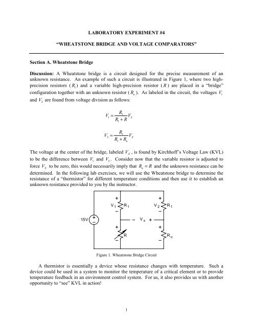
Section A. <strong>Wheatstone</strong> <strong>Bridge</strong><br />
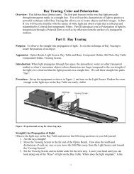
Discussion: A <strong>Wheatstone</strong> bridge is a circuit designed for the precise measurement of an<br />
unknown resistance. An example of such a circuit is illustrated in Figure 1, where two highprecision<br />
resistors ( R 1)<br />
<strong>and</strong> a variable high-precision resistor ( R ) are placed in a “bridge”<br />
configuration together with an unknown resistor ( u R ). As labeled in the circuit, the voltages 1 V<br />
<strong>and</strong> V 2 are found from voltage division as follows:<br />
R<br />
1 V1= VS<br />
R1+ R<br />
R<br />
1 V2= VS<br />
R1+ Ru<br />
The voltage at the center of the bridge, labeled V X , is found by Kirchhoff’s <strong>Voltage</strong> Law (KVL)<br />
to be the difference between V 1 <strong>and</strong> V 2 . Consider now that the variable resistor is adjusted to<br />
force V X to be zero, this would necessarily imply that Ru= R <strong>and</strong> the unknown resistance can be<br />
determined. In the following lab exercises, we will use the <strong>Wheatstone</strong> bridge to determine the<br />
resistance of a “thermistor” for different temperature conditions <strong>and</strong> then use it to establish an<br />
unknown resistance provided to you by the instructor.<br />
15V<br />
V1 R 1<br />
V2<br />
1<br />
V x<br />
R 1<br />
R Ru<br />
Figure 1. <strong>Wheatstone</strong> <strong>Bridge</strong> Circuit<br />
A thermistor is essentially a device whose resistance changes with temperature. Such a<br />
device could be used in a system to monitor the temperature of a critical element or to provide<br />
temperature feedback in an environment control system. For us, it also provides us with another<br />
opportunity to “see” KVL in action!
1. Build the circuit illustrated in Figure 1: Use the +15V supply provided on your protoboard,<br />
10 kΩ 1% resistors for R 1,<br />
the 1% 0.5W resistance substituter box for R , <strong>and</strong> the<br />
thermistor for R u . Since we want to vary the temperature of the thermistor, use protowire<br />
<strong>and</strong> alligator clips to extend its reach from the proto-board. Also, set-up the<br />
Keithley DMM to monitor the voltage V X .<br />
2. Set the Resistance Substituter box to 20 kΩ as an initial guess for the unknown<br />
resistance. Before energizing, have the instructor verify your circuit.<br />
INSTRUCTOR VERIFICATION: ___________________<br />
3. Energize the proto-board <strong>and</strong> observe the DMM measurement. If it is not zero, we will<br />
need to adjust the variable resistor. Begin the adjustment with the left-most digit. A<br />
voltage polarity reversal implies that you’ve gone too far in the opposite direction.<br />
Continue adjusting the variable resistor box digits proceeding to the right until the DMM<br />
measurement is as close to zero as possible. This is the thermistor resistance at room<br />
temperature. Record this resistance <strong>and</strong> the room temperature below.<br />
R at room temp: _______________ Room temp: ________________<br />
4. Next, obtain from the instructor an ice cube <strong>and</strong> a Ziploc baggie or some other protective<br />
sheath. Put the ice cube in the baggie <strong>and</strong> seal it. Press the ice cube against the<br />
thermistor securely <strong>and</strong> observe the DMM voltage. Adjust the resistor box to zero out the<br />
voltage reading, again beginning with the left-most digit <strong>and</strong> working rightward. Record<br />
the final resistance <strong>and</strong> the temperature of ice.<br />
R for ice: _______________ Ice temp: ________________<br />
5. Return the ice to the instructor. Next, tightly hold the thermistor between two of your<br />
fingers so that it warms beyond room temperature. When the temperature stabilizes (i.e.,<br />
the voltage stabilizes), adjust the resistor box so as to null out the voltage once again.<br />
Record the final resistance.<br />
R for fingers: _______________<br />
6. Finally, obtain a heat gun from the instructor. Carefully place the heat gun about three<br />
inches from the thermistor <strong>and</strong> activate it. After heating it for about 20 seconds, begin<br />
adjusting the resistor box to null out the DMM voltage. Record the final value of<br />
resistance.<br />
R for heat gun: _______________<br />
7. For your lab write-up, comment on the linearity of the resistance versus temperature<br />
characteristics of the thermistor. Use the following table to estimate the temperature of<br />
your fingers <strong>and</strong> the temperature obtained with the heat gun.<br />
2
Temperature (C) Resistance (kΩ)<br />
30 8.313<br />
35 6.941<br />
40 5.826<br />
45 4.912<br />
50 4.161<br />
55 3.537<br />
60 3.021<br />
65 2.589<br />
70 2.229<br />
75 1.924<br />
80 1.669<br />
85 1.451<br />
90 1.366<br />
95 1.108<br />
100 0.9375<br />
8. De-energize the power supply <strong>and</strong> remove the thermistor. Obtain an “unknown”<br />
resistance box from the instructor. Use the <strong>Wheatstone</strong> bridge technique to determine<br />
the unknown resistance. Record the value here <strong>and</strong> have the instructor verify your<br />
value. De-energize the proto-board. Replace the unknown resistor with the<br />
thermistor. Leave the circuit built on the proto-board as we will revisit it later.<br />
Section B. <strong>Voltage</strong> <strong>Comparators</strong><br />
Unknown Resistance: ________________<br />
INSTRUCTOR VERIFICATION: __________________<br />
Discussion: As the name implies, a voltage comparator is a component that allows us to<br />
determine which of two input voltages is larger. What is inside the comparator is beyond our<br />
introductory level. We prefer to “put it to use” <strong>and</strong> connect it in with concepts that we are<br />
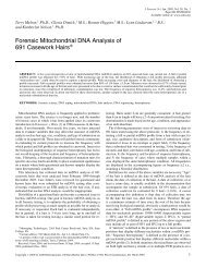
already know. The instructor should have provided you with an LM311 integrated circuit<br />
voltage comparator. A small circle on the top of the chip indicates pin 1, the remaining pins are<br />
labeled consecutively counterclockwise about the chip. A diagram of the pin-out is given in<br />
Figure 2. Note that pin 8 must be connected to a positive power supply (normally +15V), pin 4<br />
is connected to a negative power supply (normally –15V), <strong>and</strong> pin 1 is ground with respect to the<br />
comparator. The power supplies are necessary to properly bias the transistors internal to the<br />
comparator <strong>and</strong> get it to work properly.<br />
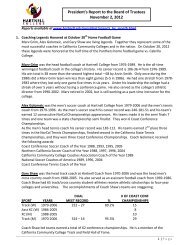
How does it work? Simple, if the voltage applied to pin 2 is less than the voltage applied<br />
to pin 3, then the output (pin 7) is internally connected to comparator ground (pin 1). If pin 2<br />
voltage is greater than pin 3 voltage, then the output assumes an open collector condition.<br />
Therefore, as illustrated in Figure 3, we must tie the output to a supply voltage through a “pullup”<br />
resistor in order to establish an output state (note this voltage could be +15V or +5V, for<br />
3
instance). That is, when pin 2 is greater than pin 3, the output of the comparator is an open<br />
circuit, so no current flows through the pull-up resistor <strong>and</strong> the output voltage will equal the<br />
supply voltage connected to the pull-up resistor. If pin 2 is less than pin 3, the output is internally<br />
shorted to ground via pin 1. The operation of the strobe input (pin 6) will be deferred until<br />
another day. Let’s get back to work!<br />
8 V+<br />
3<br />
LM311<br />
2<br />
4 6<br />
Inverting<br />
Input<br />
Output<br />
7<br />
Noninverting Comparator<br />
Input<br />
Ground<br />
1<br />
Strobe<br />
V-<br />
4<br />
1<br />
Ground<br />
2<br />
Input<br />
Input<br />
V-<br />
Figure 2. LM311 Pin-Out <strong>and</strong> Description<br />
3<br />
2<br />
+15V<br />
8<br />
LM311<br />
4 6<br />
-15V<br />
1<br />
1k<br />
V supply<br />
Output<br />
7<br />
Dual-In-Line Package<br />
3<br />
6 Balance<br />
Strobe<br />
4 5<br />
Balance<br />
Pull-up<br />
Resistor<br />
TOP VIEW<br />
Figure 3. Illustration of Open-Collector Condition<br />
8 V+<br />
7<br />
Output<br />
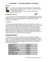
1. Build the circuit illustrated in Figure 4. To do this efficiently, connect the proto-board<br />
power supply ground to one of the long row of horizontal connected pins at the top.<br />
Insert the LM311 chip then connect the ground row to pin 1 of the LM311. A short<br />
jumper may be used to tie pins 1 <strong>and</strong> 2 together. Connect pin 8 to the proto-board +15V<br />
supply <strong>and</strong> pin 4 to the proto-board –15V supply. Connect the output pin (7) to the protoboard<br />
+5V supply via a 1 kΩ 5% resistor. Keep the proto-board de-energized.<br />
2. Connect the Tektronix function generator to the Tektronix scope. Set up the function<br />
generator to produce a 10V pk-pk, 1kHz, sinusoid with no DC offset.<br />
3. DO NOT yet apply the function generator signal to the comparator. First, run connection<br />
leads from CH1 of the scope to where the input will be applied; run connection leads
from CH2 of the scope to the output (pin 7 <strong>and</strong> ground). Have the instructor verify your<br />
circuit set-up.<br />
Function<br />
Generator<br />
INSTRUCTOR VERIFICATION: ______________________<br />
3<br />
2<br />
5<br />
+15V<br />
8<br />
LM311<br />
4 6<br />
-15V<br />
1<br />
Figure 4. LM311 Test Circuit<br />
+5V<br />
1k<br />
5%<br />
7 Output<br />
4. Energize the proto-board. Connect the function generator signal to pin 3 of the LM311<br />
<strong>and</strong> to the circuit ground. Press AUTOSET if necessary to obtain a good image on the<br />
scope screen. Sketch the waveforms <strong>and</strong> confirm that the comparator is performing as<br />
indicated in the previous discussion. If no waveform is found on CH 2, consult the<br />
instructor.<br />
5. Gently pull the DC OFFSET knob outward on the function generator. Using the scope<br />
MEASURE-MEAN feature, add 3.5V of DC offset to the function generator input.<br />
Sketch the resultant CH1 <strong>and</strong> CH2 waveforms.<br />
6. Next, adjust the DC OFFSET so that the function generator signal has a –3.5V mean<br />
value. Sketch the resultant CH1 <strong>and</strong> CH2 waveforms. Have the instructor verify your<br />
waveforms.<br />
INSTRUCTOR VERIFICATION: ______________________<br />
7. DO NOT completely disassemble your circuit, simply disconnect your function generator<br />
input <strong>and</strong> de-energize the proto-board supply. Disconnect the connections to the scope<br />
<strong>and</strong> set the scope aside.<br />
8. The final exercise will merge the two concepts we’ve investigated thus far. Modify your<br />
current circuit to the one indicated in Figure 5. Note that the jumper between pins 1 <strong>and</strong><br />
2 is removed <strong>and</strong> an LED <strong>and</strong> resistor have replaced the 1 kΩ pull-up resistor. Assuming
a voltage drop of 2.3V for the LED <strong>and</strong> a desired current of 20mA, calculate the required<br />
current-limiting resistor.<br />
Current Limit Resistor: ______________<br />
9. Set the variable resistor from the <strong>Wheatstone</strong> bridge to a value between the resistor<br />
values obtained for the thermistor at room temperature <strong>and</strong> for the thermistor pressed by<br />
the fingers. Have the instructor verify your set-up.<br />
INSTRUCTOR VERIFICATION: ______________________<br />
10. With the instructor present, energize the proto-board. Note the status of the LED at room<br />
temperature. Compress the thermistor between two of your fingers, note the status of the<br />
LED. Release the thermistor, does it return to the original status? If all has gone well,<br />
we’ve just created a rudimentary temperature monitoring instrument. Explain how the<br />
LED logic could be reversed. Test your theory by modifying the circuit.<br />
11. De-energize the proto-board. Return the thermistor <strong>and</strong> LM311 comparators to the<br />
instructor. Return the 1% precision resistors, 5% resistors, <strong>and</strong> LED to the proper bin<br />
drawers. Return all proto-wire to the bin. Place the scope, function generator, protoboard,<br />
wire kits, DMM, <strong>and</strong> resistance substituter back in the proper storage cabinet.<br />
Adj.<br />
Resistor<br />
10k<br />
1%<br />
+15V<br />
10k<br />
1%<br />
R therm<br />
6<br />
3<br />
2<br />
+15V<br />
8<br />
LM311<br />
4 6<br />
-15V<br />
1<br />
+5V<br />
Figure 5. Visual Temperature Threshold Detection Circuit<br />
R Limit<br />
Green<br />
7 Output