An Echelle Spectrometer-Spectrograph for Astronomical Use - FG ...
An Echelle Spectrometer-Spectrograph for Astronomical Use - FG ...
An Echelle Spectrometer-Spectrograph for Astronomical Use - FG ...

You also want an ePaper? Increase the reach of your titles
YUMPU automatically turns print PDFs into web optimized ePapers that Google loves.
GN<br />
t~~~~~<br />
WtA~~ />\e<br />
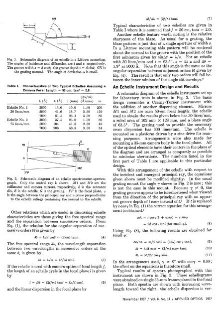
Fig. 1. Schematic diagram of an echelle in a Littrow mounting.<br />
The angles of incidence and diffraction are i and , respectively.<br />
The groove width s = d cosi; the groove depth t = d sini; GN is<br />
the grating normal. The angle of deviation d is small.<br />
Table I. Characteristics ot Two Typical <strong>Echelle</strong>s Assuming a<br />
Camera Focal Length = 50 cm, tani = 2.0<br />
(AX/Al)<br />
A (A) X () 1 (mm) (A/mm) m<br />
<strong>Echelle</strong> No. 1 3000 15.0 10.0 1.50 200<br />
30 lines/mm 5000 41.6 16.7 2.50 120<br />
7000 81.5 23.4 3.50 86<br />
<strong>Echelle</strong> No. 2 3000 37.5 25.0 1.50 80<br />
75 lines/mm 5000 104 41.8 2.50 48<br />
7000 206 58.8 3.50 34<br />
Ml<br />
G<br />
Fig. 2. Schematic diagram of an echelle spectrometer-spectrograph.<br />
Only the central ray is shown. M and M2 are the<br />
collimator and camera mirrors, respectively, S is the entrance<br />
slit, E is the echelle, G is the grating. FP is the focal plane,<br />
is the angle between the principal ray and a plane perpendicular<br />
to the echelle rulings containing the normal to the echelle.<br />
Other relations which are useful in discussing echelle<br />
characteristics are those giving the free spectral range<br />
and the separation between successive orders. From<br />
Eq. (1), the relation <strong>for</strong> the angular separation of successive<br />
orders 50 is given by<br />
6 = X/d cosG = (2/m) tani. (4)<br />
The free spectral range A), the wavelength separation<br />
between two wavelengths in successive orders at the<br />
same , is given by<br />
S<br />
S = /m = X 2 /2d sini. (5)<br />
If the echelle is used with camera optics of focal lengthf,<br />
the length of an echelle cycle in the focal plane is given<br />
by<br />
1 = f = (2f/m) tani = fX/d cosi, (6)<br />
and the linear dispersion in the focal plane by<br />
Al/AX = (2f/X) tani. (7)<br />
Typical characteristics of two echelles are given in<br />
Table I where it is assumed that f = 50 cm, tani = 2.0.<br />
<strong>An</strong>other echelle feature worth noting is the relative<br />
sharpness of the blaze. As usual <strong>for</strong> a grating, the<br />
blaze pattern is just that of a single aperture of width s.<br />
In a Littrow mounting this pattern will be centered<br />
about the normal to the groove with the position of the<br />
first minimum given by sinA = /s. For an echelle<br />
with 30 lines/mm and i = 63.50, s = 15 u and AO =<br />
1.90 at 5000 A. Note that this angle is the same as the<br />
angular separation between adjacent orders 50 given by<br />
Eq. (4). The result is that only two orders will fall between<br />
the inner minima of the single slit envelope.'<br />
<strong>An</strong> <strong>Echelle</strong> Instrument Design and Results<br />
A schematic diagram of the echelle instrument set up<br />
<strong>for</strong> laboratory tests is shown in Fig. 2. The basic<br />
design resembles a Czerny-Turner instrument with<br />
the addition of another dispersing element. Mirrors<br />
MI and M2 are each 50-cm focal length; the echelle<br />
used to obtain the results given below has 30 lines/mm,<br />
a ruled area of 102 mm X 128 mm, and a blaze angle<br />
of 63.50. The grating used to provide the necessary<br />
cross dispersion has 600 lines/mm. The echelle is<br />
mounted on a plat<strong>for</strong>m driven by a sine drive <strong>for</strong> scanning<br />
purposes. Arrangements were also made <strong>for</strong><br />
mounting a 35-mm camera body in the focal plane. All<br />
of the optical elements have their centers in the plane of<br />
the diagram and are arranged as compactly as possible<br />
to minimize aberrations. The numbers listed in the<br />
first part of Table I are applicable to this particular<br />
design.<br />
With this arrangement of the echelle with respect to<br />
the incident and emergent principal ray, the equations<br />
given above must be modified slightly. In the usual<br />
grating mount the angle -y shown in Fig. 2 is zero; this<br />
is not the case in this mount. Because y 0, the<br />
grating grooves appear to be <strong>for</strong>eshortened when viewed<br />
from the direction of the principal ray with an apparent<br />
groove depth of t cos-y instead of t.7 If t is replaced<br />
by t cos-y in Eq. (1) the correct equation <strong>for</strong> this arrangement<br />
is obtained. 7<br />
mX = t cosy(1 + coso) - s sink<br />
= 2d cosy sini (<strong>for</strong> small k). (8)<br />
Using Eq. (8), the following results are obtained <strong>for</strong><br />
small 4:<br />
AG/AX = m/d cosi = (2/X) cosy tani,<br />
30 = X/d cosi = (2/m) cos-y tani,<br />
AA = X 2 /2d cosy sini.<br />
(9)<br />
(10)<br />
(11)<br />
In the arrangement used, y = 8 with cosy = 0.99;<br />
the effect on the equations is there<strong>for</strong>e small.<br />
Typical results of spectra photographed with this<br />
instrument are shown in Fig. 3. These echellograms<br />
were obtained on single 35-mm frames placed in the focal<br />
plane. Both spectra are shown with increasing wavelength<br />
toward the right; the echelle dispersion is ver-<br />
November 1967 / Vol. 6, No. 11 / APPLIED OPTICS 1977