An Echelle Spectrometer-Spectrograph for Astronomical Use - FG ...
An Echelle Spectrometer-Spectrograph for Astronomical Use - FG ...
An Echelle Spectrometer-Spectrograph for Astronomical Use - FG ...

Create successful ePaper yourself
Turn your PDF publications into a flip-book with our unique Google optimized e-Paper software.
<strong>An</strong> <strong>Echelle</strong> <strong>Spectrometer</strong>-<strong>Spectrograph</strong> <strong>for</strong> <strong>Astronomical</strong> <strong>Use</strong><br />
Daniel J. Schroeder<br />
Introduction<br />
A compact echelle spectrometer-spectrograph has been designed <strong>for</strong> use at the Cassegrain focus of the<br />
University of Wisconsin 91-cm telescope at Pine Bluff. Laboratory results obtained with this instrument<br />
show that it has great potential <strong>for</strong> both stellar and nebular studies. Typical photographs and photoelectric<br />
scans of laboratory spectra are shown. A method of determining the profile of the echelle blaze is discussed.<br />
The instrument has high dispersion, 2.5 it/mm at 5000 X with a camera focal length of 0.5 m,<br />
and a spectral purity of 1.25 A/mm of entrance slit.<br />
Although many varieties of spectrometers and spectrographs<br />
have been developed <strong>for</strong> use in astronomy,<br />
few of these instruments utilize an echelle as the principal<br />
dispersing element. Those echelle instruments<br />
that have been built are used primarily <strong>for</strong> solar astronomy.<br />
The most famous is the echelle spectrograph of<br />
Tousey et al.,' with which excellent solar spectra have<br />
been obtained in the X2200-3500-A range. Other solar<br />
spectrographs using the echelle have been built at<br />
McMath-Hulbert Observatory 2 and at Sacramento<br />
Peak Observatory. 3 Stellar astronomers, however,<br />
have apparently made little use of the echelle, with the<br />
exception of a group at the Crimean Astrophysical<br />
Observatory. 4<br />
A study of various types of dispersing systems has<br />
shown that a combination echelle spectrometer-spectrograph<br />
of moderate size can be constructed and that<br />
it is ideally suited <strong>for</strong> application to many types of<br />
astronomical problems. Since it has become possible<br />
within the last few years to rule high quality echelle<br />
masters, this instrument shows great potential because<br />
it combines compactness with high resolution and broad<br />
spectral coverage. 5 A particular echelle design and<br />
results obtained in the laboratory with it are discussed<br />
below. Be<strong>for</strong>e discussing the features of this design,<br />
however, the general properties of the echelle are reviewed.<br />
Review of <strong>Echelle</strong> Properties<br />
The general theory of the echelle grating has been<br />
discussed by Harrison 6 and Rense 7 and only the basic<br />
results are given here. A schematic diagram of an<br />
The author was with the Space Astronomy Laboratory, University<br />
of Wisconsin, when this work was done; he is now in the<br />
Physics Department, Beloit College, Beloit, Wisconsin 53511.<br />
Received 17 July 1967.<br />
1976 APPLIED OPTICS / Vol. 6, No. 11 / November 1967<br />
echelle in a Littrow mounting is shown in Fig. 1.<br />
The equation describing its operation is<br />
mX = d(sini + sino) = t(1 + cos) - sin<br />
= 2d sini (<strong>for</strong> small 0), (1)<br />
where, as usual, n is the order number, d is the groove<br />
spacing, and i and 0 are the angles of incidence and<br />
diffraction, respectively, measured from the normal.<br />
The angular dispersion is given by<br />
and the resolving power by<br />
AO/AX = m/d cos = (2/X) tani,<br />
X/A = mN = (2Nd/X) sini = (2W/X) sini,<br />
where N is the total number of grooves and Nd is the<br />
echelle width W. Equations (2) and (3) show clearly<br />
that both the angular dispersion and the resolving power<br />
can be increased by increasing i, the angle of incidence.<br />
Equation (2), in particular, is interesting since it shows<br />
that the angular dispersion depends only on i, and not<br />
on m or d. In order to take advantage of this fact,<br />
however, it is necessary to have a grating with a large<br />
blaze angle so that it can be used at a large angle of<br />
incidence. Such gratings are called echelles and are<br />
available (from Bausch & Lomb, Inc., Rochester, New<br />
York 14602) with a blaze angle of 63°26' (tan63 0 26' =<br />
2.00). <strong>An</strong> ordinary grating with 1200 lines/mm, blazed<br />
at 5000 A in first order, has tani = 0.3 when used in a<br />
Littrow mounting. <strong>An</strong> echelle blazed as noted above<br />
will there<strong>for</strong>e show an increase of nearly a factor of<br />
seven in angular dispersion at this wavelength.<br />
<strong>Echelle</strong>s normally have rather coarse rulings (30-300<br />
lines/mm) and are there<strong>for</strong>e used in high orders (120-12<br />
at X5000 A). Because of this all wavelengths are<br />
diffracted at approximately the same angle, hence an<br />
echelle is effectively blazed <strong>for</strong> all wavelengths. Cross<br />
dispersion is necessary to separate the overlapping<br />
orders.<br />
(2)<br />
(3)
GN<br />
t~~~~~<br />
WtA~~ />\e<br />
Fig. 1. Schematic diagram of an echelle in a Littrow mounting.<br />
The angles of incidence and diffraction are i and , respectively.<br />
The groove width s = d cosi; the groove depth t = d sini; GN is<br />
the grating normal. The angle of deviation d is small.<br />
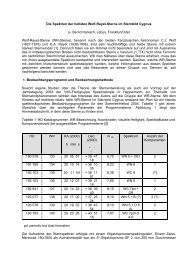
Table I. Characteristics ot Two Typical <strong>Echelle</strong>s Assuming a<br />
Camera Focal Length = 50 cm, tani = 2.0<br />
(AX/Al)<br />
A (A) X () 1 (mm) (A/mm) m<br />
<strong>Echelle</strong> No. 1 3000 15.0 10.0 1.50 200<br />
30 lines/mm 5000 41.6 16.7 2.50 120<br />
7000 81.5 23.4 3.50 86<br />
<strong>Echelle</strong> No. 2 3000 37.5 25.0 1.50 80<br />
75 lines/mm 5000 104 41.8 2.50 48<br />
7000 206 58.8 3.50 34<br />
Ml<br />
G<br />
Fig. 2. Schematic diagram of an echelle spectrometer-spectrograph.<br />
Only the central ray is shown. M and M2 are the<br />
collimator and camera mirrors, respectively, S is the entrance<br />
slit, E is the echelle, G is the grating. FP is the focal plane,<br />
is the angle between the principal ray and a plane perpendicular<br />
to the echelle rulings containing the normal to the echelle.<br />
Other relations which are useful in discussing echelle<br />
characteristics are those giving the free spectral range<br />
and the separation between successive orders. From<br />
Eq. (1), the relation <strong>for</strong> the angular separation of successive<br />
orders 50 is given by<br />
6 = X/d cosG = (2/m) tani. (4)<br />
The free spectral range A), the wavelength separation<br />
between two wavelengths in successive orders at the<br />
same , is given by<br />
S<br />
S = /m = X 2 /2d sini. (5)<br />
If the echelle is used with camera optics of focal lengthf,<br />
the length of an echelle cycle in the focal plane is given<br />
by<br />
1 = f = (2f/m) tani = fX/d cosi, (6)<br />
and the linear dispersion in the focal plane by<br />
Al/AX = (2f/X) tani. (7)<br />
Typical characteristics of two echelles are given in<br />
Table I where it is assumed that f = 50 cm, tani = 2.0.<br />
<strong>An</strong>other echelle feature worth noting is the relative<br />
sharpness of the blaze. As usual <strong>for</strong> a grating, the<br />
blaze pattern is just that of a single aperture of width s.<br />
In a Littrow mounting this pattern will be centered<br />
about the normal to the groove with the position of the<br />
first minimum given by sinA = /s. For an echelle<br />
with 30 lines/mm and i = 63.50, s = 15 u and AO =<br />
1.90 at 5000 A. Note that this angle is the same as the<br />
angular separation between adjacent orders 50 given by<br />
Eq. (4). The result is that only two orders will fall between<br />
the inner minima of the single slit envelope.'<br />
<strong>An</strong> <strong>Echelle</strong> Instrument Design and Results<br />
A schematic diagram of the echelle instrument set up<br />
<strong>for</strong> laboratory tests is shown in Fig. 2. The basic<br />
design resembles a Czerny-Turner instrument with<br />
the addition of another dispersing element. Mirrors<br />
MI and M2 are each 50-cm focal length; the echelle<br />
used to obtain the results given below has 30 lines/mm,<br />
a ruled area of 102 mm X 128 mm, and a blaze angle<br />
of 63.50. The grating used to provide the necessary<br />
cross dispersion has 600 lines/mm. The echelle is<br />
mounted on a plat<strong>for</strong>m driven by a sine drive <strong>for</strong> scanning<br />
purposes. Arrangements were also made <strong>for</strong><br />
mounting a 35-mm camera body in the focal plane. All<br />
of the optical elements have their centers in the plane of<br />
the diagram and are arranged as compactly as possible<br />
to minimize aberrations. The numbers listed in the<br />
first part of Table I are applicable to this particular<br />
design.<br />
With this arrangement of the echelle with respect to<br />
the incident and emergent principal ray, the equations<br />
given above must be modified slightly. In the usual<br />
grating mount the angle -y shown in Fig. 2 is zero; this<br />
is not the case in this mount. Because y 0, the<br />
grating grooves appear to be <strong>for</strong>eshortened when viewed<br />
from the direction of the principal ray with an apparent<br />
groove depth of t cos-y instead of t.7 If t is replaced<br />
by t cos-y in Eq. (1) the correct equation <strong>for</strong> this arrangement<br />
is obtained. 7<br />
mX = t cosy(1 + coso) - s sink<br />
= 2d cosy sini (<strong>for</strong> small k). (8)<br />
Using Eq. (8), the following results are obtained <strong>for</strong><br />
small 4:<br />
AG/AX = m/d cosi = (2/X) cosy tani,<br />
30 = X/d cosi = (2/m) cos-y tani,<br />
AA = X 2 /2d cosy sini.<br />
(9)<br />
(10)<br />
(11)<br />
In the arrangement used, y = 8 with cosy = 0.99;<br />
the effect on the equations is there<strong>for</strong>e small.<br />
Typical results of spectra photographed with this<br />
instrument are shown in Fig. 3. These echellograms<br />
were obtained on single 35-mm frames placed in the focal<br />
plane. Both spectra are shown with increasing wavelength<br />
toward the right; the echelle dispersion is ver-<br />
November 1967 / Vol. 6, No. 11 / APPLIED OPTICS 1977
N<br />
%,.-3663<br />
1 3650<br />
3655<br />
a1-3663<br />
5975 6304<br />
6128<br />
. 63 8 2<br />
N. N. N. N.64 0 2<br />
N_ 6217<br />
(a)<br />
(b)<br />
% 4047<br />
`4078<br />
6506<br />
4347<br />
N1~<br />
4358<br />
Fig. 3. Typical echellograms with representative features<br />
identified. In both photographs longer wavelengths are at the<br />
right. Entrance slit width was 0.1 mm; grating dispersion<br />
was 33 X/mm. (a) Ne discharge lamp, X5750-6700 A, (b)<br />
Hg-Cd discharge lamp, 3600-4600 A. The arrow points to<br />
two lines 0.4 A apart.<br />
tical and the entrance slit, 0.1-mm wide, is oriented<br />
parallel to the echelle grooves. A feature of this design<br />
immediately evident is the slant of the spectral<br />
lines which is present because of the angle -y. If p is<br />
the angle of a line with respect to the horizontal then,<br />
according to grating theory, 7 tanp = 2 tani siny. For<br />
the particular setup used p = 250. This feature presents<br />
no particular problem, even <strong>for</strong> scanning, since p<br />
is constant and it is necessary only to tip the exit slit<br />
by the proper amount.<br />
Examination of the Ne spectrum in Fig. 3(a) shows<br />
good imagery over the entire frame, a decrease in the<br />
echelle cycle length toward the left, and the presence of<br />
weak ghost lines symmetrically located about the<br />
strongest lines. Measurements of photomultiplier<br />
scans give a maximum ghost intensity of about 0.5%<br />
that of the parent line. The problem of ghosts is an<br />
important one and has been discussed by several<br />
authors.', The Hg-Cd spectrum in Fig. 3(b) shows<br />
the X3650-63 group of Hg and the X3610-14 group of<br />
Cd at the left side. Of particular interest here is the<br />
pair of clearly resolved lines separated by 0.4 A, X3662.9<br />
1978 APPLIED OPTICS / Vol. 6, No. 11 / November 1967<br />
and X3663.3. The dispersion in this region is about 1.8<br />
A/mm, and with an entrance slit width of 0.1 mm it<br />
should be possible to resolve lines still more closely<br />
spaced. Examination of this pair of lines shows that<br />
the predicted resolution can be reached. The effect of<br />
the blaze function is also clearly shown by this pair of<br />
lines as the upper pair is considerably stronger than the<br />
lower pair.<br />
Tracings of typical scans of spectral lines taken with<br />
0.25-mm slits are shown in Fig. 4. The line profiles<br />
are symmetric and have a measured half-intensity<br />
width that agrees with expectations. On either side<br />
of the X5770 line weak ghost lines are present. No<br />
attempt was made to separate the two overlapping<br />
orders in Fig. 4(b) which corresponds to a scan of the<br />
lower left part of Fig. 3(b). The pair of lines at X3663,<br />
which is resolved in Fig. 3(b), is not resolved in this<br />
scan because of the wider slits, but shows up as an<br />
asymmetric feature. The scan rate was approximately<br />
0.2 A/sec in the uv and 0.3 A/sec in the yellow.<br />
Examination of numerous photographs and scans<br />
in various spectral regions shows no image deterioration<br />
due to the presence of aberrations. This is true <strong>for</strong> slit<br />
widths as small as 0.1 mm, the smallest slits likely<br />
to be used on an astronomical instrument. The field<br />
is flat and there is no evidence of coma or astigmatism,<br />
at least over an area of 36 mm X 24 mm. No detailed<br />
calculations were made to account <strong>for</strong> these features,<br />
but the reasons <strong>for</strong> their absence are evident. As in a<br />
Czerny-Turner spectrometer, the coma introduced by<br />
the collimator is cancelled by the coma of the camera<br />
5770<br />
5790<br />
(a) (b)<br />
Fig. 4. Tracings of spectrometer scans taken with 0.25-mm<br />
entrance and exit slits. (a) Yellow lines of Hg with half-intensity<br />
widths of 0.9 A. (b) Two overlapping orders of Hg and Cd<br />
uv lines.
I-<br />
3 I<br />
'5790<br />
in two~~ orders.Teitniisaesae ota order 70i<br />
isatk514inorrm+I d154i re m 577 +<br />
blaze. These scans were repeated <strong>for</strong> several different<br />
wavelength settings of the small monochromator. The<br />
results of these scans show that the instrumental function<br />
of the echelle can be accurately determined and is<br />
in good agreement with the expected single-slit diffraction<br />
pattern. Figure 5 shows the envelope of these<br />
scans compared with a theoretical single-slit diffraction<br />
curve and the effect of this envelope on the measured<br />
intensities of several lines. The separation of the minima<br />
in the theoretical curve is two free spectral ranges.<br />
Application of the measured blaze function to the intensities<br />
of the Hg line pairs shows that X5790 is slightly<br />
stronger than X5770. In practice all scans are restricted<br />
to the region of width 5X centered about the peak. This<br />
function need only be determined in one spectral<br />
region as the shape is independent of wavelength;<br />
only the angular width depends on wavelength.<br />
Discussion<br />
The echelle instrument proposed above shows great<br />
potential <strong>for</strong> astronomy. As pointed out by Code and<br />
Liller 5 one of the primary considerations of an astronomical<br />
spectrometer is the bandpass, or spectral<br />
purity, at the exit slit <strong>for</strong> a given entrance slit width.<br />
Calculations show that the spectral purity AXmin is<br />
given by<br />
Figh5 Fullg crvpoe Enelope the esure chewll blaze<br />
function. Dase mncromTatcige sin-si diraction cure.-<br />
Thes pot andnteniso the width9 line H s are showuio. nh<br />
AXmi. = A/[fc. iG/AX)l, 0<br />
(12)<br />
instwo orders. Thecitroensteare scale sti X5 tat thire<br />
where As is the entrance slit width, f-0l is the collimator<br />
mo atchels the mesudiurv. Thescentro thaes lze unctiond<br />
focal length, and AG/AX is the angular dispersion. It is<br />
clear from Eq. (12) that the bandpass can be decreased<br />
mirrrif the twos irrsthven thee focal engflths.-<br />
spcrmtrwl spcrlrneteisrmna edtrmndol<br />
ucino yteehle h cel only by increasing either f-ol or the angular dispersion.<br />
thue Al design fteohrotclcmoet proposed beow the rsiduals ftessefo oma will stnd There is an obvious limit to increasing fcol since the<br />
tospradamocrmatic image.Tse in ai diton pesr-ac beam diameter at the echelle is f_/telescope f ratio.<br />
ppendicular to the ecera dirsion. Thisrhowver The real gain in reducing the bandpass is there<strong>for</strong>e<br />
effected by increasing the angular dispersion, a result<br />
destnot actrdo th ie witand rfteolution hew<br />
usua dependentoverd<br />
gtiong sectoeterazo A.de<br />
obtained by using an echelle.<br />
the etrsli insenatte<br />
A spectrometer patterned after the laboratory instru-<br />
tagntialtigdeematin imgeof setgati insit pret ment is now being built <strong>for</strong> use at the Cassegrain focus<br />
sfae. Severa Ful Inqutis cans:Enl nstrumente of the thesfocalnplanetis ouptwrete echelle maue flaelade<br />
causetitnisalocatedeatnthehpositionssofythensagittae<br />
astgmti imtaes.i Thes magesli oon alato sfacea<br />
thrug abt three echn orders55 enere on the<br />
erpven icular rleua amerasmirrorlnormal<br />
to the<br />
fature cetee (aot pea of t blzfnton The sow<br />
thestrng effect of theaeont recordedla innsities.n<br />
quaiaten dthemiation ohefre spectral net Thre<br />
<strong>for</strong>ectrequresian accuratedmeasureentaofethist blaze<br />
fuction, apetrmeuement wich sueasilyt doeri thes<br />
folloingr way. Ae tungterne amp is imae uni<strong>for</strong>ly<br />
Ao the entane sliticlcmoet ah smallm of moocromaoseatn<br />
eqivalsueto wdteatry eqalt thsetal freeet rane<br />
Svrsasof the echelle (aoutpu 60r A tX8.then mno-<br />
of the University of Wisconsin 91-cm, f/13.6 telescope<br />
at Pine Bluff. The instrument will be as shown in Fig.<br />
2 except that mirror Ml will have a focal length of 1.0 m<br />
instead of 0.5 m as in the laboratory design. Two flat<br />
mirrors will fold the entrance beam and allow the telescope<br />
axis to be perpendicular to the plane of Fig. 2.<br />
This will provide a beam diameter of 74 mm at the<br />
echelle. The camera mirror M2 will have a focal<br />
length of 0.5 m. At X5000 the dispersion is 2.50 A/mm<br />
and, because of the magnification ratio, the bandpass is<br />
1.25 A/mm of entrance slit.<br />
<strong>An</strong> echelle with 30 lines/mm, when used in series with<br />
a 600 lines/mm grating, will provide a capability of<br />
photographing 1000 A of spectrum on a single 35-mm<br />
frame with the spectral purity given above. This<br />
capability is particularly attractive when considered<br />
in conjunction with an electronic imaging device at the<br />
truhattreechelle spcrmtrrIsasd cetatd oe ths<br />
focal plane. This combination of dispersing elements,<br />
will also be used <strong>for</strong> scanning of stellar sources over<br />
small spectral regions. Because of the peculiar twodimensional<br />
nature of the focused spectrum, it will be<br />
necessary to scan both the grating and echelle to keep<br />
November 1967 / Vol. 6, No. 11 / APPLIED OPTICS 1979
the spectrum centered on the exit slit. Convenient<br />
slit widths <strong>for</strong> stellar images will give 0.5 A spectral<br />
purity.<br />
<strong>An</strong> echelle with 75 lines/mm, when used with a 1200<br />
lines/mm grating, will be particularly suited <strong>for</strong> the<br />
study of nebular sources. With this system it will be<br />
possible to use entrance holes up to 10-mm diam (160<br />
see of arc <strong>for</strong> the Pine Bluff telescope) with a spectral<br />
purity of 12.5 A. With these large apertures the finer<br />
grating will provide the necessary cross-dispersion to<br />
prevent overlapping orders when used in the first order<br />
<strong>for</strong> X>4800 A and in the second order <strong>for</strong> shorter wavelengths.<br />
The finer echelle rulings are desirable both<br />
because of the increased free spectral range and broader<br />
blaze function.<br />
The echelle spectrometer discussed above will provide<br />
high angular dispersion in a compact package <strong>for</strong> use<br />
with photomultipliers, photographic film, or electronic<br />
imaging devices. With various combinations of echelle<br />
and grating, studies of a wide variety of astronomical<br />
problems can be carried out which could not be done<br />
1980 APPLIED OPTICS / Vol. 6, No. 11 / November 1967<br />
with an ordinary grating spectrometer of comparable<br />
size.<br />
The work was supported by the National Aeronautics<br />
and Space Administration under a scientific contract.<br />
References<br />
William C. Flanagan is a research associate at 3M Company.<br />
1. R. Tousey, J. D. Purcell, and D. L. Garrett, Appl. Opt. 6,<br />
365 (1967).<br />
2. A. K. Pierce, R. R. McMath, and 0. Mohler, Astron. J. 56,<br />
137 (1951).<br />
3. H. J. Smith, Tech. Mem. GRD-TM-57-6 (1957).<br />
4. I. M. Kopylov and N. V. Steshenko, Proc. Crimean Astrophys.<br />
Obs. 33,308 (1965).<br />
5. G. R. Harrison, in Vistas in Astronomy, A. Beer, Ed. (Pergamon<br />
Press, London, 1955), Vol. 1, p. 405.<br />
6. G. R. Harrison, J. Soc. Opt. Am. 39, 522 (1949).<br />
7. W. A. Rense, Space Science Reviews, C. deJager, Ed. (Reidel<br />
Publishing Co., Holland, 1966), Vol. 5, p. 234.<br />
8. A. D. Code and W. C. Liller, in Stars and Stellar Systems,<br />
W. A. Hiltner, Ed. (Univerity of Chicago Press, Chicago,<br />
1962), Vol. 2, p. 281.