TDRSS Data Interface (TDI) - swsi.gsfc.nasa.gov - NASA
TDRSS Data Interface (TDI) - swsi.gsfc.nasa.gov - NASA
TDRSS Data Interface (TDI) - swsi.gsfc.nasa.gov - NASA

You also want an ePaper? Increase the reach of your titles
YUMPU automatically turns print PDFs into web optimized ePapers that Google loves.
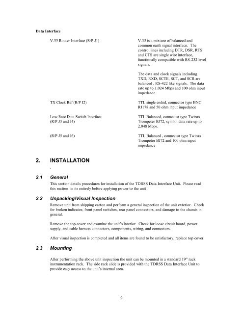
<strong>Data</strong> <strong>Interface</strong><br />
V.35 Router <strong>Interface</strong> (R/P J1) V.35 is a mixture of balanced and<br />
common earth signal interface. The<br />
control lines including DTR, DSR, RTS<br />
and CTS are single wire interface,<br />
functionally compatible with RS-232 level<br />
signals.<br />
6<br />
The data and clock signals including<br />
TXD, RXD, SCTE, SCT, and SCR are<br />
balanced , RS-422 like signals. The data<br />
rate up to 1.024 Mbps and 100 ohm input<br />
impedance.<br />
TX Clock Ref (R/P J2) TTL single ended, connector type BNC<br />
RJ178 and 50 ohm input impedance<br />
Low Rate <strong>Data</strong> Switch <strong>Interface</strong><br />
(R/P J3 and J4)<br />
(R/P J5 and J6)<br />
2. INSTALLATION<br />
.<br />
2.1 General<br />
TTL Balanced, connector type Twinax<br />
Trompeter BJ72, symbol data rate up to<br />
2.048 Mbps.<br />
TTL Balanced , connector type Twinax<br />
Trompeter BJ72 and 100 ohm input<br />
impedance<br />
This section details procedures for installation of the <strong>TDRSS</strong> <strong>Data</strong> <strong>Interface</strong> Unit. Please read<br />
this section in its entirely before applying power to the unit<br />
2.2 Unpacking/Visual Inspection<br />
Remove unit from shipping carton and perform a general inspection of the unit exterior. Check<br />
for broken indicator, front panel switches, rear panel connectors, and damage to the chassis in<br />
general.<br />
Remove the top cover and examine the unit’s interior. Check for loose circuit board, power<br />
supply, and cable harness connectors, components, wiring, and connectors.<br />
After visual inspection is completed and all items are found to be satisfactory, replace top cover.<br />
2.3 Mounting<br />
After performing the above unit inspection the unit can be mounted in a standard 19” rack<br />
instrumentation rack. The side rack slide is provided with the <strong>TDRSS</strong> <strong>Data</strong> <strong>Interface</strong> Unit to<br />
provide easy access to the unit’s internal area.