TDRSS Demand Access Service: Application of Advanced Technology
TDRSS Demand Access Service: Application of Advanced Technology
TDRSS Demand Access Service: Application of Advanced Technology

You also want an ePaper? Increase the reach of your titles
YUMPU automatically turns print PDFs into web optimized ePapers that Google loves.
1<br />
Paper ID: 5a003<br />
<strong>TDRSS</strong> DEMAND ACCESS SERVICE: APPLICATION OF<br />
ADVANCED TECHNOLOGY TO ENHANCE USER OPERATIONS<br />
David J. Zillig*, D. Robert McOmber**, and Neil Fox***<br />
*NASA/GSFC, Microwave Systems Branch, Code 567, Greenbelt, MD 20771<br />
Phone: (301) 286-8003, Fax: (301) 286-1724, e-mail: David.J.Zillig@gsfc.nasa.gov<br />
**Stanford Telecom, 1761 Business Center Drive, Suite 200, Reston, VA 20190<br />
Phone: (703) 438-8064, Fax: (703) 438-8112, e-mail: rmcomber@sed.stel.com<br />
***Stanford Telecom, 1761 Business Center Drive, Suite 200, Reston, VA 20190<br />
Phone: (703) 438-7843, Fax: (703) 438-8112, e-mail: nfox@sed.stel.com<br />
ABSTRACT<br />
Current operations <strong>of</strong> the NASA Tracking and Data Relay Satellite System (<strong>TDRSS</strong>) provide access to<br />
services based on a service schedule which is generated from user requests . Normally completed<br />
days in advance, this schedule is based upon estimates <strong>of</strong> user needs and mission event timelines. The<br />
desire to provide service to smaller missions and at reduced cost makes implementation <strong>of</strong> efficient<br />
service allocation approaches desirable. Fortunately, technology advances occurring over the past<br />
several years now make it possible to enhance <strong>TDRSS</strong> Multiple <strong>Access</strong> operations to such an extent<br />
that service on demand is now achievable. In particular, hardware advances permitting<br />
implementation <strong>of</strong> very low cost beamformers and receivers can permit augmentation <strong>of</strong> the MA<br />
return link capability to provide each <strong>TDRSS</strong> user with a dedicated return link antenna beam for<br />
communications. Additionally, incorporation <strong>of</strong> new ground station equipment will greatly enhance<br />
operations for the MA forward link shared resource. This paper provides an overview <strong>of</strong> the<br />
technologies that enable this new <strong>TDRSS</strong> service capability and describes the significant benefits to<br />
user operations arising from the <strong>Demand</strong> <strong>Access</strong> service.<br />
1 INTRODUCTION<br />
NASA uses the Space Network, which includes the <strong>TDRSS</strong>, to provide reliable low- and high-data<br />
rate relay services between user spacecraft in Earth orbit and the ground. <strong>TDRSS</strong> consists <strong>of</strong> several<br />
communication spacecraft in geostationary orbit as well as ground terminals located at the White<br />
Sands Complex (WSC) in White Sands, New Mexico. <strong>TDRSS</strong> provides forward (user control centerto-user<br />
spacecraft) services, which include satellite and instrument commanding, and return (user<br />
spacecraft-to-user control center) services, which include both science data and satellite telemetry.<br />
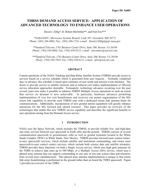
<strong>TDRSS</strong> provides these functions via both a Single <strong>Access</strong> service, which uses high gain antennas on<br />
the TDRS to achieve data rates up to 300 Mbps, or a Multiple <strong>Access</strong> (MA) service, which uses a<br />
phased array antenna that can support commanding to one user or low-rate science data and telemetry<br />
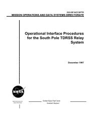
from several users simultaneously. This phased array antenna implementation is unique in that return<br />
link array beamforming is performed on the ground rather than on board the TDRS spacecraft. Figure<br />
1 provides an overview <strong>of</strong> one TDRS.
TDRS<br />
S-band<br />
Array<br />
2<br />
MA Return <strong>Service</strong><br />
• 30 element array<br />
• Ground based beamforming<br />
• Multiple array beams<br />
• ~3° beamwidth<br />
MA Forward <strong>Service</strong><br />
• 12 elements with Tx capability<br />
• On-board beamforming<br />
• Single beam<br />
• ~7° beamwidth<br />
Figure 1: A Tracking and Data Relay Satellite (TDRS)<br />
Paper ID: 5a003<br />
Current operations <strong>of</strong> <strong>TDRSS</strong> provide access to services based on a schedule <strong>of</strong> the available<br />
communications links which is generated from user requests . Normally completed days in advance,<br />
this schedule is based upon estimates <strong>of</strong> user needs and mission event timelines. The desire to provide<br />
service to smaller missions and at reduced cost makes implementation <strong>of</strong> efficient service allocation<br />
approaches desirable. <strong>TDRSS</strong> users have additionally expressed an interest in new, innovative service<br />
types such as spacecraft initiated emergency notifications and science alerts. Fortunately, technology<br />
advances occurring over the past several years now make it possible to enhance <strong>TDRSS</strong> Multiple<br />
<strong>Access</strong> operations to such an extent that service on demand is now achievable. In particular, hardware<br />
advances permitting implementation <strong>of</strong> very low cost beamformers and receivers can permit<br />
augmentation <strong>of</strong> the MA return link capability to provide each <strong>TDRSS</strong> user with a dedicated return<br />
link antenna beam for communications. Additionally, incorporation <strong>of</strong> new ground station equipment<br />
will greatly enhance operations for the MA forward link shared resource.<br />
This <strong>Demand</strong> <strong>Access</strong> (DA) concept will automate service on demand, providing substantial benefits to<br />
<strong>TDRSS</strong> users and the <strong>TDRSS</strong> Network at low cost and with no changes to either the TDRS or user<br />
spacecraft [1]. In this paper, the <strong>TDRSS</strong> <strong>Demand</strong> <strong>Access</strong> capability now under development is<br />
presented. Key technology advances that enable the <strong>Demand</strong> <strong>Access</strong> implementation are defined and<br />
the substantial benefits to user operations brought about by these changes are described.<br />
2 THE CURRENT MA RETURN LINK ARCHITECTURE<br />
The WSC contains distinct equipment clusters (called Space Ground Link Terminals or SGLTs) for<br />
each TDRS supported. Four SGLTs within the existing WSC support the MA service along with<br />
another SGLT under development in Guam). Together two TDRS spacecraft supported by the WSC<br />
SGLTs along with a TDRS supported by the Guam terminal can provide full-time line-<strong>of</strong>-sight<br />
visibility to most Earth orbiting users.<br />
As mentioned above, the MA return link service from a user spacecraft to a TDRS is supported using a<br />
phased array antenna on-board the TDRS. This 30 element, S-band phased array is unique in that the<br />
phase shifting and combining operations necessary for beamforming are not performed on board the<br />
TDRS. Instead, the 30 element channels <strong>of</strong> received user data are frequency division multiplexed<br />
(FDM) then transmitted to the TDRS ground terminal where beamforming and signal demodulation<br />
are ultimately performed. Using multiple sets <strong>of</strong> beamforming equipment and associated<br />
demodulators within a single SGLT, and taking advantage <strong>of</strong> the fact that user signals are spread
3<br />
Paper ID: 5a003<br />
spectrum with unique pseudo-noise (PN) codes, permits the TDRS to support multiple simultaneous<br />
users via a CDMA architecture.<br />
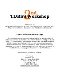
Figure 2 provides an overview <strong>of</strong> the currently existing <strong>TDRSS</strong> MA return link architecture showing<br />
relevant equipment within a single WSC SGLT along with an outline <strong>of</strong> the data flow to the user<br />
control centers. Within the SGLT, the 30 FDM MA return channels from a single TDRS are first<br />
separated into 30 analog channels at a common intermediate frequency by the Element Separator.<br />
Next, each <strong>of</strong> the 30 channels is digitized within the A/D Quad Splitter and output as two channels <strong>of</strong><br />
8-bit digital data representing In-phase and Quadrature components sampled at 8.5 Msps. These 60<br />
digital channels are then distributed to each beamformer/receiver.<br />
As illustrated, a single WSC SGLT supporting MA return service contains six beamformer/receiver<br />
combinations. Of these six, five are made available for user service and one set <strong>of</strong> equipment is<br />
dedicated to array calibration. Thus five simultaneous MA return link users can be supported and each<br />
user receives the full gain <strong>of</strong> the TDRS phased array. These five links per TDRS have been fully<br />
adequate to support the community <strong>of</strong> orbiting spacecraft using an operations concept based on prior<br />
scheduling. But, as described below, new operations concepts become feasible if more return links<br />
can be provided.<br />
3 THE RETURN LINK DA CONCEPT<br />
3.1 STATEMENT OF NEED<br />
The evolution towards smaller, lower cost space missions has led to an increased user need for<br />
streamlined mission support and a strong desire for autonomous spacecraft operation. Toward these<br />
goals, NASA GSFC has investigated and initiated implementation <strong>of</strong> a substantial change to the<br />
<strong>TDRSS</strong> MA return link service. Through an expansion <strong>of</strong> the MA service, users desiring such a<br />
capability will be able to obtain a continuously available MA return link to their spacecraft. Not only<br />
can the previous scheduling process be largely bypassed by users needing reduced operational<br />
complexity but, for the first time, it will be possible for a user spacecraft to initiate <strong>TDRSS</strong> return link<br />
communications without prior coordination by the user operations center. These changes will be<br />
implemented by expanding the number <strong>of</strong> MA return links available on the current <strong>TDRSS</strong> spacecraft<br />
and providing appropriate control/data routing equipment.<br />
3.2 TECHNICAL APPROACH<br />
The combination <strong>of</strong> array beamforming and user signal PN spreading provides a high degree <strong>of</strong><br />
separation among user signals within an MA return link demodulator. The TDRS architecture, if<br />
provided with sufficient beamformers and demodulators, could support a large number <strong>of</strong> return link<br />
users provided that individual user data rates are sufficiently low (hundreds <strong>of</strong> users at 1-10 kbps –<br />
depending on user duty cycle).<br />
In the past, costs associated with such expansion <strong>of</strong> the MA return service capability were prohibitive.<br />
The current WSC beamformers were implemented with 1980’s technology and each beamformer<br />
requires 30 circuit cards and occupies one full chassis <strong>of</strong> a 30 inch wide equipment rack. To<br />
understand the need for this level <strong>of</strong> complexity, consider that each beamformer receives a complete<br />
copy <strong>of</strong> the sampled data for all 30 array elements: 60 sampled channels (for I and Q) x 8 bits per<br />
sample x 8.5 Msps gives 4.08 Gbps processed by each beamformer. While the phase shifting and<br />
combining within each beamformer are not complicated operations, the data handling operations
6<br />
6<br />
Amplify/<br />
Convert to IF<br />
Element<br />
Separator<br />
A/D Quad<br />
Splitter<br />
MA Return<br />
Link Equipment<br />
30<br />
2 Beamformer<br />
1<br />
2 1 Integrated<br />
Receiver<br />
Controller<br />
SGLT<br />
Control/Data<br />
Interface<br />
&<br />
Data<br />
Handling<br />
Functions<br />
4<br />
Network<br />
Control<br />
User Control<br />
Centers<br />
Figure 2: The Existing MA Return Link Architecture<br />
Paper ID: 5a003<br />
required to deal with this volume <strong>of</strong> data (both moving it among the individual circuit cards <strong>of</strong> a<br />
beamformer, and transporting it to all beamformers) are quite complex. Additionally, to meet<br />
redundancy requirements, each beamformer was further burdened by the need to perform a set <strong>of</strong><br />
calculations (noise covariance matrix estimation) that were common to all the beamformers.<br />
The 1990’s have brought about substantial evolution in both digital processors and in data networking<br />
equipment. Taking advantage <strong>of</strong> these advancements, development <strong>of</strong> a new generation <strong>TDRSS</strong><br />
beamformer has been initiated. The new beamformer implementation is expected to achieve a factor<br />
<strong>of</strong> five reduction in beamformer size and nearly a factor <strong>of</strong> ten reduction in per unit costs.<br />
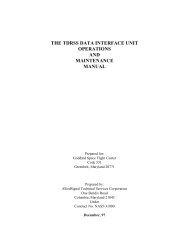
Figure 3 provides an overview <strong>of</strong> the new beamformer architecture that emphasizes the signal<br />
multiplexing architecture. As a key first step in the development <strong>of</strong> the new beamformer concept,<br />
functionality was split between an Element Multiplexer/Correlator (EMC) unit and Individual<br />
Beamformer Units (IBUs). The EMC accepts the element data from the existing WSC A/D Quad<br />
Splitter, performs those calculations that were previously common to all beamformers, and distributes<br />
all beamforming data to the IBUs. Data distribution relies on a commercial <strong>of</strong>f-the-shelf Network<br />
Transparent Switch (NTS). Data from six array elements is time division multiplexed together (giving<br />
five groups <strong>of</strong> six elements) then fed to the NTS for distribution to IBU Groups (IBUGs) containing<br />
five IBUs. Each IBUG contains a matching NTS receiver which demultiplexes the TDM data and<br />
distributes it to the IBUs.<br />
The NTS, in conjunction with modern high speed digital processing, greatly facilitates the beamformer<br />
implementation. A single EMC can support fifteen IBUGs for a total <strong>of</strong> 75 IBUs in the illustrated<br />
configuration. It is also possible, however, to use a single output from the EMC Network Transparent<br />
Switch transmitter to feed a distribution unit (based again on the same NTS switch) that regenerates<br />
the data for transmission to still more IBUGs. This flexible architecture can support hundreds <strong>of</strong><br />
beamformers per SGLT – far more than are currently anticipated.<br />
GSFC
1<br />
2<br />
•<br />
•<br />
•<br />
30<br />
A /<br />
D<br />
Q UADSPLITTER<br />
I,Q-1<br />
I,Q-6<br />
I,Q-25<br />
I,Q-30<br />
A/D Quad digitizes<br />
into 30 channels each<br />
@:<br />
1. I &Q<br />
2. 8 bits<br />
3. Rate = 8.5 MHz<br />
EMC Node<br />
Board -1<br />
(Mux)<br />
•<br />
•<br />
•<br />
EMC Node<br />
Board -5<br />
(Mux)<br />
1.0625<br />
Gbps<br />
1<br />
5<br />
Network<br />
Transparent<br />
Switch (NTS)<br />
‘5’ to 15x’5’<br />
(Creates 15<br />
copies)<br />
EMC Node Board<br />
Muxes 6 Channel I,Q<br />
pairs<br />
= 6x(8+8+1)x8.5 MHz<br />
+ Overhead<br />
= 1.0625 Gbps<br />
1<br />
2<br />
15<br />
5 x1.0625<br />
Gbps<br />
•<br />
•<br />
•<br />
5<br />
5<br />
EMC IBUG<br />
5<br />
To other<br />
IBUGs<br />
EMC NTS<br />
Provides 15<br />
sets <strong>of</strong> the<br />
5 1.0625<br />
Gbps Data<br />
5<br />
Network<br />
Transparent<br />
Switch (NTS)<br />
‘5’ to 5x’5’<br />
(Creates 5<br />
Copies)<br />
IBUG NTS<br />
Provides 5<br />
sets <strong>of</strong> the<br />
5 1.0625<br />
Gbps Data<br />
5 x1.0625<br />
Gbps<br />
5<br />
1<br />
Transition<br />
Module -1<br />
(Serial to<br />
Parallel)<br />
Paper ID: 5a003<br />
<strong>Demand</strong> <strong>Access</strong> demodulators will also be relatively inexpensive and much smaller than the current<br />
units and will also <strong>of</strong>fer some performance improvements relative to the current WSC demodulators.<br />
Not only will the demodulator realize cost improvements due to advances in technology since the<br />
1980s, the relatively large number <strong>of</strong> demodulators that will be produced will lower production costs<br />
by distributing non-recurring engineering costs over more units.<br />
One potential performance gain is in acquisition time. The ongoing NASA demodulator prototyping<br />
effort has centered around Charge Coupled Device (CCD) technology which allows rapid PN code<br />
correlation evaluations in the analog domain.<br />
Figure 4 illustrates the planned architecture <strong>of</strong> the new beamformers and demodulators within an<br />
SGLT <strong>of</strong> the WSC. The existing A/D Quad Splitters <strong>of</strong> the WSC have spare outputs available for<br />
connection <strong>of</strong> the new equipment. Existing beamformers and receivers within the WSC will not be<br />
affected by the service expansion. Automatic data routing (not illustrated) <strong>of</strong> all received MA return<br />
link data to the appropriate user control center is planned.<br />
5<br />
5<br />
•<br />
•<br />
•<br />
Transition<br />
Module -5<br />
(Serial to<br />
Parallel)<br />
1<br />
•<br />
•<br />
20 IBU -1<br />
5<br />
•<br />
20<br />
(Weight<br />
& Sum)<br />
20 Parallel<br />
Lines Each<br />
53.125 MHz<br />
1<br />
•<br />
•<br />
20 IBU -5<br />
5<br />
•<br />
20<br />
(Weight<br />
& Sum)<br />
Transition Module<br />
Converts Serial to 20<br />
bit Parallel<br />
Reduces each 1.0625<br />
Gbps to 20 53.125 MHz<br />
lines<br />
Figure 3: The Beamformer Signal Multiplexing Architecture<br />
•<br />
•<br />
•<br />
IBU<br />
Combines all<br />
30 channels;<br />
Output is a 6<br />
MHz Signal
6<br />
6<br />
Amplify/<br />
Convert to IF<br />
Element<br />
Separator<br />
A/D Quad<br />
Splitter<br />
Existing MA Return<br />
Link Equipment<br />
30<br />
2 Beamformer<br />
1<br />
2 1 Integrated<br />
Receiver<br />
Controller<br />
Ancillary Data<br />
Ethernet<br />
Hub<br />
Element Multiplexer/<br />
Correlator (EMC)<br />
3.3 MA RETURN DA OPERATIONS CONCEPTS<br />
6<br />
Distribution<br />
Unit (Option)<br />
Beamforming SystemA<br />
IBU Group N<br />
IBU Group 1<br />
Paper ID: 5a003<br />
Implementation <strong>of</strong> large numbers <strong>of</strong> beamformer/demodulator combinations in the MA Return DA<br />
architecture will permit users desiring a continuously available return link to attain this goal by having<br />
a dedicated beamformer/receiver combination on each <strong>of</strong> three <strong>TDRSS</strong> SGLTs. The user spacecraft<br />
need not transmit continuously. Only the ground equipment will be continuously configured – able to<br />
receive and demodulate user return data whenever the user spacecraft transmits. Figure 5 illustrates<br />
some <strong>of</strong> the operations scenarios supported by the new architecture. These are:<br />
1. Normal MA Return <strong>Service</strong> without Scheduling. It must be emphasized that the DA<br />
architecture does not preclude use <strong>of</strong> the MA return link in its traditional role for support <strong>of</strong><br />
planned user service events.<br />
2. Unplanned Return Transmission. For the first time, in the <strong>TDRSS</strong> system, user spacecraft<br />
will be able to initiate return service without prior coordination/planning by the user<br />
operations center. Low-cost, autonomous spacecraft collecting science data will be able to<br />
return that data whenever necessary (either via the MA return link or by using the DA service<br />
to request a higher rate service). Data may be immediately returned from unpredictable<br />
targets <strong>of</strong> opportunity (such as astronomical events). Another key application <strong>of</strong> spacecraft<br />
initiated service is the ability <strong>of</strong> the user spacecraft to immediately notify the mission<br />
operations center in the event <strong>of</strong> an anomaly or emergency situation. This option has<br />
generated considerable interest among users that plan to use <strong>TDRSS</strong> services.<br />
3. Non-Space User Data Collection. With proper frequency coordination, the <strong>TDRSS</strong><br />
architecture can provide support to non-space users. Because the <strong>TDRSS</strong> MA return link<br />
IBU 1<br />
Demod 1<br />
IBU 2<br />
Demod 2<br />
IBU 3<br />
Demod 3<br />
IBU 4<br />
Demod Group 1<br />
Demod 4<br />
IBU 5<br />
Demod Group N<br />
Multiplex<br />
Figure 4: The Return Link <strong>Demand</strong> <strong>Access</strong> Architecture<br />
Demod 5<br />
To Additional<br />
IBU Groups<br />
MA Return Data<br />
for Multiple Users
1<br />
Normal MA Return<br />
<strong>Service</strong><br />
<strong>TDRSS</strong> Spacecraft<br />
2<br />
NASA Communications<br />
Network<br />
Example<br />
User<br />
WSC User Operations<br />
Uses: • Normal science data return without scheduling<br />
• Acknowledgements to forward link commands<br />
• Acknowledgements to DA forward services<br />
3<br />
Non-Space User<br />
Data Collection<br />
<strong>TDRSS</strong> Spacecraft<br />
4<br />
Internet<br />
Buoys<br />
WSC User Data Center<br />
Use: Random access low data rate transmissions<br />
7<br />
<strong>TDRSS</strong> Spacecraft<br />
Uses: • Sensor detection <strong>of</strong> target <strong>of</strong> opportunity<br />
• Contingency telemetry (Emergency service)<br />
• Test/Characterization<br />
Paper ID: 5a003<br />
antenna beam (with 3.2° beamwidth) covers a large footprint on the Earth, there is the<br />
possibility <strong>of</strong> supporting a large community <strong>of</strong> low duty cycle users within the footprint <strong>of</strong> a<br />
single beamformer. Using multiple demodulators connected to a single beamformer would<br />
permit simultaneous service by a number <strong>of</strong> low data rate users.<br />
4. Polling. Another possibility currently under consideration is MA return link polling. For<br />
those users desiring the benefits <strong>of</strong> spacecraft initiated service that cannot afford dedicated<br />
beamformers, a beamformer/demodulator shared with other users could be used. By<br />
periodically scanning the community <strong>of</strong> users participating in this service, a user spacecraft<br />
transmitting data can be identified and then handed <strong>of</strong>f to another beamformer/demodulator<br />
for data extraction. The efficiency <strong>of</strong> such a service depends on the number <strong>of</strong> users<br />
participating and their requirements for return link service.<br />
4 THE FORWARD LINK DA CONCEPT<br />
Unplanned Return<br />
Transmission<br />
Example<br />
User<br />
WSC<br />
NASA Communications<br />
Network<br />
User Operations<br />
Principal Investigator<br />
<strong>TDRSS</strong><br />
Polling<br />
User 2<br />
User 1<br />
WSC<br />
NASA Communications<br />
Network<br />
User Operations<br />
Shared beamformer/demod hops from user to user<br />
Figure 5: Return Link DA Operations Concepts<br />
While a TDRS can support multiple simultaneous MA return link services, only a single MA forward<br />
(TDRS-to-user spacecraft) link is supported per TDRS spacecraft. For this reason, the MA forward<br />
link DA service concept focuses on efficient allocation <strong>of</strong> the MA forward link among TDRS users<br />
rather than on technology to expand the existing service capability. The forward link DA concept will<br />
automate the user service request process for MA forward service – allocating service to users on a<br />
first-come first-served basis. For short duration user services (
8<br />
Paper ID: 5a003<br />
that individual users will obtain the forward link without the need to wait for other user services to<br />
complete.<br />
While the forward DA implementation does not rely on state-<strong>of</strong>-the-art technology, it should be noted<br />
that standard interfaces and protocols will be used wherever feasible within the architecture. The use<br />
<strong>of</strong> standardized approaches to the user interface, provide substantial cost and operational advantages to<br />
the user community that were not possible when the <strong>TDRSS</strong> was conceived in the 1970s.<br />
5 SUMMARY<br />
This paper has shown how incorporation <strong>of</strong> new technologies into an existing satellite<br />
communications architecture can not only enhance user operations, but also make available new user<br />
operations concepts not originally conceived by the system implementers. The new <strong>Demand</strong> <strong>Access</strong><br />
<strong>Service</strong> capabilities should be available to the community <strong>of</strong> <strong>TDRSS</strong> users in 2000.<br />
REFERENCE<br />
1. D. Zillig, R.McOmber, & W.D. Horne, "<strong>Demand</strong> <strong>Access</strong> <strong>Service</strong> for <strong>TDRSS</strong> Users," AIAA 16th<br />
International Communications Satellite Systems Conference, Washington, DC, 25-29 February 1996