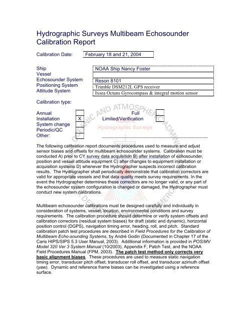
Hydrographic Surveys Multibeam Echosounder Calibration ... - NOAA
Hydrographic Surveys Multibeam Echosounder Calibration ... - NOAA
Hydrographic Surveys Multibeam Echosounder Calibration ... - NOAA

You also want an ePaper? Increase the reach of your titles
YUMPU automatically turns print PDFs into web optimized ePapers that Google loves.
<strong>Hydrographic</strong> <strong>Surveys</strong> <strong>Multibeam</strong> <strong>Echosounder</strong><br />
<strong>Calibration</strong> Report<br />
<strong>Calibration</strong> Date:<br />
Ship<br />
Vessel<br />
<strong>Echosounder</strong> System<br />
Positioning System<br />
Attitude System<br />
<strong>Calibration</strong> type:<br />
February 18 and 21, 2004<br />
<strong>NOAA</strong> Ship Nancy Foster<br />
Reson 8101<br />
Trimble DSM212L GPS receiver<br />
Ixsea Octans Gyrocompass & integral motion sensor<br />
Annual<br />
Full<br />
Installation<br />
System change<br />
Periodic/QC<br />
X Limited/Verification<br />
Other:<br />
_______________________________________<br />
The following calibration report documents procedures used to measure and adjust<br />
sensor biases and offsets for multibeam echosounder systems. <strong>Calibration</strong> must be<br />
conducted A) prior to CY survey data acquisition B) after installation of echosounder,<br />
position and vessel attitude equipment C) after changes to equipment installation or<br />
acquisition systems D) whenever the Hydrographer suspects incorrect calibration<br />
results. The Hydrographer shall periodically demonstrate that calibration correctors are<br />
valid for appropriate vessels and that data quality meets survey requirements. In the<br />
event the Hydrographer determines these correctors are no longer valid, or any part of<br />
the echosounder system configuration is changed or damaged, the Hydrographer must<br />
conduct new system calibrations.<br />
<strong>Multibeam</strong> echosounder calibrations must be designed carefully and individually in<br />
consideration of systems, vessel, location, environmental conditions and survey<br />
requirements. The calibration procedure should determine or verify system offsets and<br />
calibration correctors (residual system biases) for draft (static and dynamic), horizontal<br />
position control (DGPS), navigation timing error, heading, roll, and pitch. Standard<br />
calibration patch test procedures are described in Field Procedures for the <strong>Calibration</strong> of<br />
<strong>Multibeam</strong> Echo-sounding Systems, by André Godin (Documented in Chapter 17 of the<br />
Caris HIPS/SIPS 5.3 User Manual, 2003). Additional information is provided in POS/MV<br />
Model 320 Ver 3 System Manual (10/2003), Appendix F, Patch Test, and the <strong>NOAA</strong><br />
Field Procedures Manual (FPM, 2003). The patch test method only corrects very<br />
basic alignment biases. These procedures are used to measure static navigation<br />
timing error, transducer pitch offset, transducer roll offset, and transducer azimuth offset<br />
(yaw). Dynamic and reference frame biases can be investigated using a reference<br />
surface.
Pre-calibration Survey Information<br />
Reference Frame Survey<br />
(IMU, sensor, GPS antenna offsets and rotation with respect to vessel reference frame)<br />
Vessel reference frame defined with respect to:<br />
X<br />
IMU X Reference Position<br />
Reference to IMU Lever Arm<br />
X(m) Y(m) Z(m)<br />
1.24 18.31 0<br />
IMU frame wrt vessel reference frame<br />
Reference to Sensor Lever Arm<br />
X(m) Y(m) Z(m)<br />
6.50 -3.20 3.44<br />
Measurements verified for this calibration.<br />
Drawing and table attached.<br />
Drawing and table included with project<br />
report/DAPR:<br />
Position/Motion Sensor <strong>Calibration</strong> (for Ixsea Octans Gyrocompass)<br />
<strong>Calibration</strong> date: 11/15/2000<br />
Reference to primary GPS Lever Arm<br />
X(m) Y(m) Z(m)<br />
-0.76 2.54 -4.24<br />
Heave Settings: Bandwidth up to<br />
100Hz<br />
Damping Period auto<br />
Firmware version 3.2 was used on DN 49. The system was upgraded to version<br />
4.6 on DN 51, which was used for the remainder of the survey. No lever arm<br />
offsets were entered into the Octans.<br />
Static Draft Survey<br />
(Vessel waterline with respect to vessel reference frame)<br />
Survey date: 2/18/2004
On DN 49 while alongside in Frederiksted the vessel took on fuel and water. The<br />
transducer draft measurement (z-value for Swath 1) in the VCF was based on a fully<br />
loaded vessel. The pole mounting the sonar was marked off in decimeter graduations<br />
from the transducer face. This allowed the Hydrographer to determine, to within a<br />
centimeter or two, the waterline setting. Readings of the waterline were observed when<br />
the pole was deployed. Post fueling, the draft of the Reson sonar unit measured 3.44<br />
meters, and the distance from the waterline to RP measured 1.87 meters. This showed a<br />
difference of .127 meters lower in the water prior to taking on fuel and water. Waterline<br />
corrector values were added into the vessel configuration file is CARIS.<br />
Static Draft Correction (meters)<br />
Dynamic Draft Survey<br />
(Vessel waterline with respect to vessel reference frame and vessel speed)<br />
No dynamic draft survey was conducted for this vessel.<br />
<strong>Calibration</strong> Area<br />
Site Description<br />
On February 18, 2004 prior to the start of survey operations a comparison between the<br />
multibeam and single beam systems was conducted alongside the pier in Old San Juan,<br />
PR. The ships single beam sonar (Abyss IES-10) measured a depth of 25.2 ft., and the<br />
multibeam nadir beam measured 24.7 ft. The estimated draft of the ships singlebeam<br />
transducer was 10 ft. The measured draft of the multibeam unit was 11 ft 2 inches. The<br />
calculated comparison was 35.2 ft (SB) – 35.9 ft (MB) = a difference of 0.7 ft. This<br />
general agreement gave the Lead Hydrographer, at least some confidence in the<br />
multibeams proper installation and operation. A more detailed comparison was not<br />
possible due to the not knowing the actual draft of the ships single beam transducer.<br />
The Nancy Foster patch test was started on February 18, 2004 (DN 49) at 17°39'32.27" N<br />
064°55'06.92" W; (296475.05, 1953489.27), south west of Frederiksted, St. Croix. Water<br />
depths at the site ranged from 17-256 meters. The bathymetry of the site consisted of two<br />
main components. The first was a steep slope (75 deg) in water depths ranging from 57<br />
174 meters. The second was a relatively flat area, with depths of approximately 20<br />
meters. A successful patch test was not able to be conducted due to several factors<br />
including site selection (the water depths exceeding sonar system limitations), lack of<br />
time to run all the lines, and the vessel not being on line due to helm/OOD inexperience.<br />
Despite this lines run on DN 49 were deemed sufficient to determine the roll bias error.<br />
All other values were determined using later patch test data.
DN 49 Patch Site<br />
Between February 18 and resumption of the patch test on the 21st the Nancy Foster was<br />
tied up along side in Frederiksted. During this time the patch test data collected on DN<br />
49 was evaluated, and vessel measurements obtained. In addition, the OCTANS was<br />
upgraded with a new firmware version (V.4.6) that provided the unit with a real-time self<br />
adjusting heave filter.<br />
On February 21, 2004 (DN 52) the patch test was continued at a site north west of<br />
Frederiksted, at 17°45'05.39" N 064°53'44.55" W; (299006.21 , 1963706.41). The patch<br />
test was conducted on the site of a charted fish haven. The bathymetry of the site<br />
consisted of a gently sloping bottom (7.5 degree slope), in water depths ranging from 15<br />
30 meters. Three prominent and one minor wrecks were located with the patch test site.<br />
Data acquisition during the patch test was complicated by the vessel again having<br />
difficulties staying on line, the general shoal nature of the patch test site, and time<br />
constraints due to the vessel needing to begin dive operations.<br />
DN 52 Patch Site
Site and Line Diagram<br />
X<br />
X<br />
Submarine Feature<br />
Line(s) Position Depth Description<br />
052-1353<br />
052-1400<br />
052-1412<br />
052-1427<br />
052-1353<br />
052-1400<br />
052-1412<br />
052-1427<br />
17 45 04.45 N<br />
064 53 45.98 W<br />
17 45 06.22 N<br />
064 53 44.46 W<br />
052-1412 17 45 10.20 N<br />
064 53 43.71 W<br />
052-1412 17 45 09.91 N<br />
064 53 42.62 W<br />
<strong>Calibration</strong> Lines<br />
18 M Barge (60 x 17 x 3.5 M)<br />
17 M Wreck 1 (40 x 7 x 3 M)<br />
26 M Wreck 2 (56 x 13 x 4.6 M)<br />
17 M Wreck 3 (26.5 x 7.5 x 4 M)<br />
Correction<br />
Hypack Caris Azimuth Speed Yaw Pitch Timing Roll Transducer<br />
Line Line<br />
11 049-0024 141 4.5 X 1<br />
11 049-0036 321 4.5 X 1<br />
5 052-1353 17 2 X X 1<br />
5 052-1400 197 2 X 1<br />
5 052-1412 197 6 X X 1<br />
5 052-1427 17 6 X X 1<br />
4 052-1435 197 2 1<br />
5 052-1353 17 2 X 1<br />
Copy of acquisition logs attached.<br />
Sound Velocity Correction<br />
Measure water sound velocity (SV) prior to survey operations in the immediate vicinity of<br />
the calibration site. Conduct SV observations as often as necessary to monitor changing<br />
conditions and acquire a SV observation at the conclusion of calibration proceedings. If<br />
SV measurements are measured at the transducer face, monitor surface SV for changes<br />
and record surface SV with profile measurements.
Sound Velocity Measurements<br />
Max.<br />
Surface<br />
Change<br />
Position<br />
Time Depth SV<br />
Observed<br />
?<br />
Latitude Longitude<br />
04049150 239.3 1539.2 17 Ε 40’ 01.7” N 064 Ε 55’ 47.7 “W<br />
04520512 190.1 1539.3 17 Ε 44’ 48.0” N 064 Ε 54’ 09.0” W<br />
Tide Correction<br />
Gauge ID<br />
9751639 Charlotte Amalie,VI and 9751401 Lime Tree Bay, VI<br />
Approximate distance of gauge from calibration site: 9 and 40 (n.<br />
mi.)<br />
respectively<br />
Approximate water level range at calibration site:<br />
.018<br />
(meters)<br />
Water level corrections applied:<br />
X Predicted Verified<br />
Preliminary<br />
Zoned Note: Patch was processed using predicted tides, not zoned. Post survey<br />
all data was tide corrected using Verified zoned tides.<br />
Data Acquisition and Processing Guidelines<br />
Initially, calibration measurement offsets should be set to zero in vessel configuration<br />
files. Static and dynamic draft offsets, inertial measurement unit (IMU) lever arm offsets,<br />
and vessel reference frame offsets must be entered in appropriate software applications<br />
prior to bias analysis. Perform minimal cleaning to eliminate gross flyers from sounding<br />
data.<br />
Navigation Timing Error (NTE)<br />
Measure NTE correction through examination of a profile of the center beams from lines<br />
run in the same direction at maximum and minimum vessel speeds. NTE is best<br />
observed in shallow water.<br />
Transducer Pitch Offset (TPO)<br />
Apply NTE correction. Measure TPO correction through examination of a profile of the<br />
center beams from lines run up and down a bounded slope or across a conspicuous<br />
feature. Acquire data on lines oriented in opposite directions, at the same vessel speed.<br />
TPO is best observed in deep water.
Transducer Roll Offset (TRO)<br />
Apply NTE and TPO corrections. Measure the TRO correction through examination of<br />
roll on the outer beams across parallel overlapping lines. TRO is best observed over flat<br />
terrain in deep water. An additional check for TRO adjustment can be performed by<br />
running two lines parallel to a sloped surface.<br />
Transducer Azimuth Offset (TAO or yaw)<br />
Apply NTE, TPO and TRO corrections. Measure TAO correction through examination of<br />
a conspicuous topographic feature observed on the outer beams of lines run in opposite<br />
directions.<br />
Patch Test Results and Correctors<br />
Evaluator NTE (sec) TPO (deg) TAO (deg) TRO (deg)<br />
Rooney 0.0 -3.6 -2.4 +0.25<br />
Final Values 0.0 -3.6 -2.4 -0.9<br />
Corrections calculated in:<br />
X<br />
Caris ISIS<br />
Other<br />
Caris Vessel Configuration File<br />
Name: Nancy Foster<br />
Version:<br />
5.3 Sp 3 hot fix 25<br />
New X Appended values with time tag<br />
Comments:<br />
A 1 meter artifact was observed during main scheme data acquisition.<br />
The source of the artifact could not be determined during the survey,<br />
possible sources include an improper setting in the Octans<br />
gyrocompass, or a miss measured lever arm.<br />
Additional calibration or action recommended:
The patch test data will be forwarded to Gerd Glang at UNH for<br />
further review.<br />
Evaluator: Sean Rooney<br />
Reviewed by:<br />
Accepted by: