GR-150XL-1 - Tadano America Corporation
GR-150XL-1 - Tadano America Corporation
GR-150XL-1 - Tadano America Corporation

You also want an ePaper? Increase the reach of your titles
YUMPU automatically turns print PDFs into web optimized ePapers that Google loves.
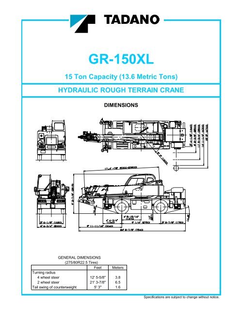
<strong>GR</strong>-<strong>150XL</strong><br />
15 Ton Capacity (13.6 Metric Tons)<br />
HYDRAULIC ROUGH TERRAIN CRANE<br />
DIMENSIONS<br />
GENERAL DIMENSIONS<br />
(275/80R22.5 Tires)<br />
Feet Meters<br />
Turning radius<br />
4 wheel steer 12' 5-5/8" 3.8<br />
2 wheel steer 21' 3-7/8" 6.5<br />
Tail swing of counterweight 5' 3" 1.6<br />
Specifications are subject to change without notice.
CRANE SPECIFICATIONS<br />
BOOM WIRE ROPE - Warrington seal wire, extra improved plow steel,<br />
Six section full power synchronized telescoping boom, preformed, independent wire rope core, right regular lay.<br />
17.4'~78' (5.3m~23.8m), of box construction with 4 sheaves, 7/16" (11.2mm) 6x37 class<br />
9-5/16" (0.236m) root diameter, at boom head. Maximum Permissible Line Pull (Main) : 5,450lbs (2,470kg)<br />
The synchronization system consists of two double acting Maximum Permissible Line Pull (Auxiliary) : 5,730lbs (2,600kg)<br />
telescope cylinders , extension cables and retraction cables.<br />
Hydraulic cylinder fitted with holding valve. Boom telescope HOOK BLOCKS<br />
sections are supported by wear pads both vertically and horizontally. 15 ton (13.6 metric ton)- Weighted hook block with swivel and safety latch.<br />
Extension speed 60.6' (18.5m) in 52 seconds. 2.0 ton (1.8 metric ton) - Weighted hook ball with swivel and safety latch.<br />
BOOM ELEVATION - By a double acting hydraulic cylinder with<br />
holding valve. Elevation -3<br />
o ~82 o , combination controls for hand HYDRAULIC SYSTEM<br />
or foot operation.<br />
Automatic speed reduction and soft stop function. PUMPS - Two variable piston pumps for crane functions.<br />
Elevation speed -3 o to 82 o in 29 seconds Tandem gear pump for steering, swing and accumulator.<br />
Powered by carrier engine. Pump disconnect for crane is<br />
JIB - Two stage extension type with 5<br />
o , 25 o ,45 o or 60 o<br />
engaged/ disengaged by rotary switch from operator's cab.<br />
offset(tilt type). Single sheave, 8" (0.203m) root diameter, at jib head.<br />
Box type top section telescopes from box type base section CONTROL VALVES - Multiple valves actuated by pilot pressure<br />
which stores under base boom section. with integral pressure relief valves.<br />
Jib length is 11.8' (3.6m) or 18' (5.5m).<br />
RESERVOIR - 45 gallon (172 lit.) capacity. External sight level<br />
AUXILIARY LIFTING SHEAVE (SINGLE TOP) (OPRIONAL) gauge.<br />
Single sheave, 8" (0.203m) root diameter. Mounted to main<br />
boom head for single line work. FILTRATION - BETA10=10 return filter, full flow with bypass<br />
protection, located inside of hydraulic reservoir. Accessible for<br />
ANTI-TWO BLOCK - Pendant type over-winding cut out device easy replacement.<br />
with audio-visual (FAILURE lamp/BUZZER) warning system.<br />
OIL COOLER - Air cooled fan type.<br />
SWING<br />
Hydraulic axial piston motor through planetary swing speed<br />
reducer. Continuous 360 o full circle swing on ball bearing turn CAB AND CONTROLS<br />
table at 2.4min -1 {rpm}. Equipped with manually locked/released<br />
swing brake. A 360 o positive swing lock for pick and carry and travel Both crane and drive operations can be performed from one cab<br />
modes. mounted on rotating superstructure.<br />
Right side, 1 man type, steel construction with sliding door access<br />
HOIST and safety glass windows opening at side. Door window is<br />
powered control. Windshield glass window and roof glass window<br />
MAIN HOIST - Grooved drum driven by hydraulic axial piston are shatter-resistant. Tilt-telescoping steering wheel. Adjustable<br />
motor through winch speed reducer. Power load lowering and control lever for swing, boom elevating, boom telescoping,<br />
raising. Equipped with automatic brake (neutral brake) and auxiliary hoist and main hoist. Control lever can change<br />
counterbalance valve. Controlled independently of auxiliary hoist. neutral positions and tilt for easy access to cab. 3 way adjustable<br />
Equipped with cable follower and drum rotation indicator. operator's seat with high back, headrest and armrest. Engine<br />
throttle knob. Foot operated controls: boom elevating,<br />
DRUM - Grooved 10-7/16" (0.265m) root diameter x 9-7/16" (0.239m) boom telescoping, service brake and engine throttle.<br />
wide. Wire rope: 433' of 7/16" diameter rope (132m of 11.2mm). Hot water cab heater and air conditioning.<br />
Drum capacity: 486.8' (148.4m) 7 layers.<br />
Maximum line pull (available): 6,700lbs. (3,050kg). Dash-mounted engine start/stop, monitor lamps, cigarette lighter,<br />
Maximum line speed: 410FPM (125m/min) at the 5th layer. drive selector switch, parking brake switch, steering mode<br />
select switch, power window switch, pump engaged/disengaged<br />
AUXILIARY HOIST - Grooved drum driven by hydraulic axial switch, swing brake switch and outrigger controls.<br />
piston motor through winch speed reducer. Power load lowering<br />
and raising. Equipped with automatic brake (neutral brake) and Instruments - Torque converter oil temperature, engine water<br />
counterbalance valve. Controlled independently of main hoist. temperature, air pressure, fuel, speedometer, tachometer,<br />
Equipped with cable follower and drum rotation indicator. hour meter and odometer / tripmeter. Hydraulic oil pressure is<br />
monitored and displayed on the AML-C display panel.<br />
DRUM - Grooved 10-7/16" (0.265m) root diameter x 9-7/16" (0.239m)<br />
wide. Wire rope: 217' of 7/16" diameter rope (66m of 11.2mm).<br />
Drum capacity: 486.8' (148.4m) 7 layers.<br />
Maximum line pull (available): 6,700lbs. (3,050kg).<br />
Maximum line speed: 361FPM (110m/min) at the 3rd layer.<br />
2
<strong>Tadano</strong> electronic LOAD MOMENT INDICATOR system TADANO AML-C monitors outrigger extended length and<br />
(AML-C) including: automatically programs the corresponding "RATED LIFTING<br />
Control lever lockout function<br />
Boom position indicator<br />
CAPACITIES" table<br />
Outrigger state indicator Operator's left hand console includes transmission gear selector<br />
Boom angle / boom length / jib offset angle / jib length / load and sight level bubble. Upper console includes roof washer<br />
radius / rated lifting capacities / actual loads read out and wiper switch, emergency outrigger set up key switch,<br />
Ratio of actual load moment to rated load moment jib equipped/removed select switch and air conditioning control<br />
indication switch.<br />
Automatic Speed Reduction and Soft Stop function<br />
on boom elevation and swing<br />
Working condition register switch<br />
Load radius / boom angle / tip height / swing range NOTE: Each crane motion speed is based on unladen<br />
preset function conditions.<br />
External warning lamp<br />
Tare function<br />
Drum rotation indicator (audible and visible type) main and<br />
auxiliary hoist<br />
CARRIER SPECIFICATIONS<br />
Lower console includes working light switch and boom emergency<br />
telescoping switch (2nd-3rd and 4th-top).<br />
TYPE - Rear engine, left hand steering, driving axle 2-way SUSPENSION - Front: Semi-elliptic leaf springs with hydraulic<br />
selected type by manual switch, 4x2 front drive, 4x4 front and lockout device. Rear: Semi-elliptic leaf springs with hydraulic<br />
rear drive. lockout device.<br />
FRAME - High tensile steel, all welded mono-box construction. BRAKE SYSTEMS - Service: Air over hydraulic disc brakes on<br />
all 4 wheels. Parking/Emergency: Spring applied-air released<br />
TRANSMISSION - Electronically controlled full automatic brake acting on input shaft of front axle. Auxiliary: Electrotransmission.<br />
Torque converter driving full powershift with pneumatic operated exhaust brake.<br />
driving axle selector. 6 forward and 2 reverse speeds, constant<br />
mesh. TIRES - 275/80R22.5<br />
3 speeds - high range - 2 wheel drive; 4 wheel drive<br />
3 speeds - low range - 4 wheel drive OUTRIGGERS - Four hydraulic, beam and jack outriggers.<br />
Vertical jack cylinders equipped with integral holding valve. Each<br />
TRAVEL SPEED - 30.4 mph (49 km/h) outrigger beam and jack is controlled independently from cab.<br />
Beams extend to 15' 5" (4.7 m) center-line and retract to<br />
AXLE - Front: Full floating type, steering and driving axle. within 5' 4-1/2" (1.64 m) overall width with floats. Outrigger jack<br />
AXLE - Rear: Full floating type, steering and driving axle. floats are attached thus eliminating the need of manually<br />
attaching and detaching them. Controls and sight bubble located<br />
STEERING- Hydraulic power steering controlled by steering in superstructure cab. Four outrigger extension lengths are<br />
wheel. Four steering modes available: 2 wheel front, 2 wheel rear, provided with corresponding "RATED LIFTING CAPACITIES" for<br />
4 wheel coordinated and 4 wheel crab. crane duty in confined areas.<br />
Min. Extension 5' 4-1/2" (1.64m) center to center<br />
Mid. Extension 8' 2-3/8" (2.5m) center to center<br />
Mid. Extension 11' 5-3/4" (3.5m) center to center<br />
Mid. Extension 14' 1-1/4" (4.3m) center to center<br />
Max. Extension 15' 5" (4.7m) center to center<br />
Float size(Diameter) 1' 1- 3/4" (0.35m)<br />
ENGINE<br />
Model Mitsubishi 4M50-TLA3B [Tier 3] Radiator Fin and tube core, thermostat controlled<br />
Type Direct injection diesel Fan, in.(mm) Suction type, 10-blade, 18 (457) dia.<br />
No. of cylinders 4 Starting 24 volt<br />
Combustion 4 cycle, turbo charged and after cooled Charging 24 volt system, negative ground<br />
BoreXStroke, in.(mm) 4.488 X 4.724 (114X120) Battery 2-80 amp. Hour<br />
Displacement, cu. in (liters) 299 (4.900) Compressor, air, CFM(l /min) 21.6 CFM (612) at 2,700rpm<br />
Air inlet heater 24 volt preheat Output, Max. HP (kW) Gross 172 (129) at 2,700rpm<br />
Air cleaner Dry type, replaceable element Torque, Max. ft-lb (Nm) 390 (529) at 1,600rpm<br />
Oil filter Full flow with replaceable element Capacity, gal.(liters)<br />
Fuel filter Full flow with replaceable element Cooling water 2.9 (11)<br />
Fuel tank, gal.(liters) 50 (189), right side of carrier Lubrication 201 ~ 2.9 (8 ~11)<br />
Cooling Liquid pressurized, recirculating by-pass Fuel 50 (189)<br />
3
STANDARD EQUIPMENT<br />
- Six section full power partially synchronized boom - Mitsubishi 4M50-TL turbo charged after<br />
17.4' ~ 78' (5.3 m~23.8 m) cooled engine (172HP) with exhaust brake<br />
- Main hoist with grooved drum and 433' of 7/16" cable. - Electronic controlled automatic transmission driven<br />
- Drum rotation indicator (visible type) main hoist by torque converter<br />
- Anti-Two block device (overwind cutout) - 4 X 4 X 4 drive/steer<br />
- <strong>Tadano</strong> electronic load moment indicator system (AML-C) - Semi-elliptic leaf springs suspension with hydraulic lockout<br />
- Outrigger extension length detector<br />
device (front and rear)<br />
- Electronic crane monitoring system - 275/80R22.5 tires<br />
- Self centering finger control levers with pilot control - Disc brakes<br />
- Control pedals for boom elevating and boom telescoping - Fenders<br />
- 3 way adjustable cloth seat with armrests, high back - Air dryer<br />
and seat belt - Water separator with filter<br />
- Tilt-telescoping steering wheel - Engine over-run alarm<br />
- Tinted safety glass and sun visor - Back-up alarm<br />
- Front windshield wiper and washer - Low oil pressure/high water temp. warning device (visual)<br />
- Roof window wiper and washer - Rear steer centering light<br />
- Power window (cab door - Air cleaner dust indicator<br />
- Rear view mirrors (right and left side) - Full instrumentation package<br />
- Cigarette lighter - Complete highway light package<br />
- Cab floor mat - Tool storage compartment<br />
- Pump disconnect in operator's cab - Tire inflation kit<br />
- Hydraulic oil cooler - 24 volt electric system<br />
- Hot water cab heater and air conditioner - 2.0 ton (1.8 metric ton) hook ball with swivel<br />
- Work lights - 15 ton (13.6 metric ton) hook block with swivel<br />
- Independently controlled outriggers - Towing hooks-Front and rear<br />
- Five outrigger extension positions - Fuel consumption monitor (#FD2021~)<br />
- Self-storing outrigger pads - Eco mode system (#FD2247~)<br />
OPTIONAL EQUIPMENT<br />
- 11.8' or 18' (3.6 m or 5.5 m) box jib (tilt type)<br />
with 5 o , 25 o , 45 o and 60 o pinned offsets and self storing pins.<br />
- Auxiliary lifting sheave (single top) stowable.<br />
- Auxiliary hoist with grooved drum and 217' of 16" cable and<br />
drum rotation indicator (visual type)<br />
HOISTING PERFORMANCE<br />
LINE SPEEDS AND PULLS DRUM WIRE ROPE CAPACITIES<br />
Drum grooved lagging<br />
Line pulls<br />
Available<br />
7/16" (11.2mm) wire rope<br />
2 Main or auxiliary hoist - 10'-7/8" (0.28m)<br />
drum<br />
Layer<br />
Line speeds<br />
Total wire rope<br />
F.P.M. m/min Lbs. kgf Feet Meters<br />
1st 308 94 6700 3050 1 57.0 17.4<br />
2nd 330 101 6200 2810 2 118.3 36.0<br />
3rd 361 108 5700 2610 3 183.6 56.0<br />
4th 375 114 5400 2430 4 253.2 77.2<br />
5th 410 121 5000 2280 5 326.9 99.6<br />
6th 420 128 4700 2140 6 404.8 123.4<br />
7th 443 135 4500 2020 7 486.8 148.4<br />
* Maximum permissible line pull may be affected by wire rope strength.<br />
1<br />
Wire<br />
rope<br />
layer<br />
DRUM DIMENSIONS<br />
1<br />
Line speeds based only on hook block, not loaded. Inch mm<br />
2<br />
Developed by machinery with each layer of wire rope, but not based Root diameter 10-7/16" 265<br />
on rope strength or other limitation in machinery or equipment. Length 9-7/16" 239<br />
Flange diameter 1' 5-11/16" 450<br />
4
NOTE: Boom and jib geometry shown are for unloaded<br />
condition and machine standing level on firm<br />
supporting surface.<br />
Boom deflection and subsequent radius and boom<br />
angle change must be accounted for when applying<br />
load to hook.<br />
<strong>GR</strong>-<strong>150XL</strong> WORKING RANGE CHART<br />
5
<strong>GR</strong>-<strong>150XL</strong> RATED LIFTING CAPACITIES (IN POUNDS)<br />
ON OUTRIGGERS FULLY EXTENDED 15' 5"(4.7m) SPREAD<br />
360 o ROTATION<br />
A 17.4' 30' 42' 54' 66' 78'<br />
B C (5.3m) C (9.0m) C (12.7m) C (16.4m) C (20.1m) C (23.8m)<br />
4' 70 30,000 79 13,200<br />
5' 67 30,000 77 13,200 81 13,200<br />
6' 63 28,800 75 13,200 80 13,200<br />
8' 54 23,800 71 13,200 77 13,200 80 11,000<br />
10' 44 17,800 67 13,200 74 13,200 78 11,000 80 9,900<br />
12' 31 14,800 62 13,200 71 13,200 76 11,000 79 9,900 81 6,600<br />
15' 55 11,500 67 11,100 72 10,850 76 8,950 79 6,600<br />
20' 42 8,300 59 8,000 67 7,750 72 7,050 75 6,050<br />
25' 20 6,200 50 5,850 61 5,700 67 5,500 71 4,950<br />
30' 39 4,050 54 4,400 62 4,400 67 4,100<br />
35' 25 2,950 47 3,350 57 3,550 63 3,350<br />
40' 39 2,650 51 3,150 58 2,800<br />
45' 28 1,950 45 2,400 54 2,350<br />
50' 38 1,850 49 2,000<br />
55' 29 1,400 43 1,550<br />
60' 16 1,050 37 1,250<br />
65' 30 1,000<br />
70' 20 770<br />
D 0<br />
LIFTING CAPACITIES AT ZERO DE<strong>GR</strong>EE BOOM ANGLE ON OUTRIGGERS FULLY EXTENDED<br />
15' 5"(4.7m) SPREAD 360 o ROTATION<br />
A 17.4' 30' 42' 54' 66' 78'<br />
C B (5.3m) B (9.0m) B (12.7m) B (16.4m) B (20.1m) B (23.8m)<br />
0 o<br />
13.1' 13,500 25.3' 5,900 37.4' 2,600 49.5' 1,600 61.7' 1,000 73.8' 600<br />
ON OUTRIGGERS FULLY EXTENDED 14' 1-1/4"(4.3m) SPREAD<br />
360 o ROTATION<br />
A 17.4' 30' 42' 54' 66' 78'<br />
B C (5.3m) C (9.0m) C (12.7m) C (16.4m) C (20.1m) C (23.8m)<br />
4' 70 30,000 79 13,200<br />
5' 67 30,000 77 13,200 81 13,200<br />
6' 63 28,800 75 13,200 80 13,200<br />
8' 54 23,800 71 13,200 77 13,200 80 11,000<br />
10' 44 17,800 67 13,200 74 13,200 78 11,000 80 9,900<br />
12' 31 14,800 62 13,200 71 13,200 76 11,000 79 9,900 81 6,600<br />
15' 55 11,300 67 11,100 72 10,850 76 8,950 79 6,600<br />
20' 42 8,050 59 7,450 67 7,750 72 7,050 75 6,050<br />
25' 20 5,500 50 5,300 61 5,400 67 5,100 71 4,950<br />
30' 39 3,500 54 4,050 62 4,100 67 3,900<br />
35' 25 2,500 47 2,850 57 3,200 63 3,200<br />
40' 39 2,100 51 2,300 58 2,550<br />
45' 28 1,450 45 1,750 54 1,950<br />
50' 38 1,250 49 1,500<br />
55' 29 900 43 1,150<br />
60' 16 600 37 900<br />
65' 30 600<br />
D 0 23<br />
LIFTING CAPACITIES AT ZERO DE<strong>GR</strong>EE BOOM ANGLE ON OUTRIGGERS FULLY EXTENDED<br />
14' 1-1/4"(4.3m) SPREAD 360 o ROTATION<br />
A 17.4' 30' 42' 54' 66'<br />
C B (5.3m) B (9.0m) B (12.7m) B (16.4m) B (20.1m)<br />
0 o<br />
13.1' 13,200 25.3' 5,200 37.4' 2,000 49.5' 1,100 61.7' 500<br />
A :Boom length in feet<br />
B :Load radius in feet<br />
C :Loaded boom angle ( o )<br />
D :Minimum boom angle ( o ) for indicated length (no load)<br />
NOTE: The lifting capacity data stored in the LOAD MOMENT INDICATOR (AML-C) is based on the standard<br />
number of parts of line listed in the chart.<br />
Standard number of parts of line for each boom length should be according to the following table.<br />
Boom length in feet 17.4' 17.4' to 78' Single top<br />
(meters) (5.3m) (5.3m to 23.8m) Jib<br />
Number of parts of line 8 4 1<br />
6
<strong>GR</strong>-<strong>150XL</strong> RATED LIFTING CAPACITIES (IN POUNDS)<br />
ON OUTRIGGERS FULLY EXTENDED 11' 5-3/4"(3.5m) SPREAD<br />
360 o ROTATION<br />
A 17.4' 30' 42' 54' 66' 78'<br />
B C (5.3m) C (9.0m) C (12.7m) C (16.4m) C (20.1m) C (23.8m)<br />
4' 70 30,000 79 13,200<br />
5' 67 30,000 77 13,200 81 13,200<br />
6' 63 28,800 75 13,200 80 13,200<br />
8' 54 23,800 71 13,200 77 13,200 80 11,000<br />
10' 44 17,800 67 13,200 74 13,200 78 11,000 80 9,900<br />
12' 31 14,800 62 13,200 71 13,200 76 11,000 79 9,900 81 6,600<br />
15' 55 10,150 67 10,000 72 9,450 76 8,950 79 6,600<br />
20' 42 5,800 59 5,550 67 6,300 71 6,550 75 5,950<br />
25' 20 3,600 50 3,400 60 4,050 67 4,400 71 4,500<br />
30' 39 2,100 54 2,650 61 3,000 67 3,100<br />
35' 25 1,250 47 1,800 56 2,050 62 2,250<br />
40' 38 1,150 51 1,350 58 1,550<br />
45' 28 700 45 950 53 1,050<br />
50' 37 650 48 700<br />
55' 43 450<br />
D 0 26 39<br />
LIFTING CAPACITIES AT ZERO DE<strong>GR</strong>EE BOOM ANGLE ON OUTRIGGERS FULLY EXTENDED<br />
11' 5-3/4"(3.5m) SPREAD 360 o ROTATION<br />
A 17.4' 30' 42' 54'<br />
C B (5.3m) B (9.0m) B (12.7m) B (16.4m)<br />
0 o<br />
13.1' 13,200 25.3' 3,300 37.4' 1,000 49.5' 400<br />
ON OUTRIGGERS FULLY EXTENDED 8' 2-3/8"(2.5m) SPREAD<br />
360 o ROTATION<br />
A 17.4' 30' 42' 54' 66' 78'<br />
B C (5.3m) C (9.0m) C (12.7m) C (16.4m) C (20.1m) C (23.8m)<br />
4' 70 30,000 79 13,200<br />
5' 67 30,000 77 13,200 81 13,200<br />
6' 63 28,800 75 13,200 80 13,200<br />
8' 54 18,700 71 13,200 77 13,200 80 11,000<br />
10' 44 12,200 67 11,800 74 11,800 78 11,000 80 9,900<br />
12' 31 8,800 62 8,600 71 8,550 76 9,250 79 9,900 81 6,600<br />
15' 55 5,450 66 5,350 72 6,000 76 6,300 79 6,600<br />
20' 42 2,850 58 2,750 66 3,300 71 3,600 75 3,850<br />
25' 20 1,500 50 1,350 60 1,900 66 2,200 70 2,350<br />
30' 39 500 54 1,000 61 1,350 66 1,450<br />
35' 47 500 56 750 62 850<br />
40' 58 450<br />
D 0 30 41 49 55<br />
LIFTING CAPACITIES AT ZERO DE<strong>GR</strong>EE BOOM ANGLE ON OUTRIGGERS FULLY EXTENDED<br />
8' 2-3/8"(2.5m) SPREAD 360 o ROTATION<br />
A 17.4' 30'<br />
C B (5.3m) B (9.0m)<br />
0 o<br />
13.1' 7,400 25.3' 1,300<br />
ON OUTRIGGERS FULLY EXTENDED 5' 4-1/2"(1.64m) SPREAD<br />
360 o ROTATION<br />
A 17.4' 30' 42' 54' 66' 78'<br />
B C (5.3m) C (9.0m) C (12.7m) C (16.4m) C (20.1m) C (23.8m)<br />
4' 70 17,500 79 13,200<br />
5' 67 15,300 77 12,800 81 12,500<br />
6' 63 13,250 75 12,300 80 12,500<br />
8' 54 8,650 71 8,800 77 8,300 80 7,500<br />
10' 44 5,800 67 6,100 74 5,600 78 5,600 80 5,600<br />
12' 30 4,250 62 4,100 71 4,050 75 4,200 78 4,300 80 4,350<br />
15' 55 2,450 66 2,300 72 2,700 76 3,000 78 3,100<br />
20' 42 900 59 750 66 1,250 71 1,550 74 1,800<br />
25' 70 950<br />
D 0 26 52 58 63 67<br />
LIFTING CAPACITIES AT ZERO DE<strong>GR</strong>EE BOOM ANGLE ON OUTRIGGERS FULLY EXTENDED<br />
8' 2-3/8"(2.5m) SPREAD 360 o A<br />
ROTATION<br />
17.4'<br />
C B (5.3m)<br />
0 o<br />
13.1' 3,500<br />
A :Boom length in feet B :Load radius in feet C :Loaded boom angle ( o ) D :Minimum boom angle ( o ) for indicated length (no load)<br />
NOTE: The lifting capacity data stored in the LOAD MOMENT INDICATOR (AML-C) is based on the standard<br />
number of parts of line listed in the chart.<br />
Standard number of parts of line for each boom length should be according to the following table.<br />
Boom length in feet 17.4' 17.4' to 78' Single top<br />
(meters) (5.3m) (5.3m to 23.8m) Jib<br />
Number of parts of line 8 4 1<br />
7
<strong>GR</strong>-<strong>150XL</strong> RATED LIFTING CAPACITIES (IN POUNDS)<br />
ON OUTRIGGERS FULLY EXTENDED 15' 5"(4.7m) SPREAD<br />
360 o ROTATION<br />
78' (23.8m) Boom + 11.8' (3.6m) Jib 78' (23.8m) Boom + 18' (5.5m) Jib<br />
C 5 o offset 25 o offset 45 o offset 60 o offset C 5 o offset 25 o offset 45 o offset 60 o offset<br />
R W R W R W R W R W R W R W R W<br />
82 12.6' 3,300 16.7' 2,650 19.6' 2,000 21.5' 1,400 82 13.9' 1,850 20.0' 1,550 24.7' 1,300 27.2' 850<br />
82 16.1' 3,300 20.0' 2,650 22.7' 2,000 24.6' 1,400 82 17.5' 1,850 23.5' 1,550 28.0' 1,300 30.1' 850<br />
77.5 20.4' 3,300 24.2' 2,650 26.5' 2,000 28.1' 1,400 77.5 21.9' 1,850 27.9' 1,550 31.9' 1,200 33.9' 850<br />
75 24.4' 3,300 28.1' 2,650 30.3' 2,000 31.9' 1,400 75 26.3' 1,850 32.1' 1,550 35.8' 1,200 37.4' 850<br />
72.5 28.3' 3,000 31.8' 2,400 33.9' 1,900 35.3' 1,400 72.5 30.6' 1,850 36.0' 1,500 39.6' 1,200 41.2' 850<br />
70 32.1' 2,750 35.4' 2,200 37.4' 1,850 38.9' 1,400 70 34.7' 1,850 39.7' 1,400 43.1' 1,150 44.5' 850<br />
67.5 35.7' 2,500 38.9' 2,100 40.8' 1,800 41.9' 1,400 67.5 38.6' 1,800 43.3' 1,350 46.5' 1,100 47.9' 850<br />
65 39.2' 2,300 42.3' 1,950 44.2' 1,700 45.3' 1,400 65 42.5' 1,750 47.1' 1,300 49.8' 1,100 50.9' 850<br />
62.5 42.8' 2,100 45.7' 1,850 47.3' 1,600 48.1' 1,400 62.5 46.1' 1,600 50.5' 1,250 53.0' 1,100 54.0' 850<br />
60 46.1' 1,950 49.0' 1,750 50.3' 1,550 51.1' 1,400 60 49.6' 1,450 53.8' 1,200 56.1' 1,050 56.8' 850<br />
57.5 49.1' 1,750 51.9' 1,600 53.3' 1,500 57.5 53.1' 1,350 57.2' 1,150 59.1' 1,000<br />
55 52.1' 1,550 54.9' 1,400 56.0' 1,400 55 56.4' 1,250 60.3' 1,100 61.9' 1,000<br />
52.5 55.1' 1,300 57.7' 1,200 58.6' 1,200 52.5 59.5' 1,100 63.3' 1,000 64.7' 950<br />
50 57.9' 1,100 60.3' 1,000 61.2' 1,050 50 62.7' 1,000 66.0' 900 67.4' 900<br />
47.5 60.7' 950 62.8' 900 63.6' 900 47.5 65.4' 850 68.7' 800 69.8' 800<br />
45 63.2' 800 65.3' 750 65.8' 750 45 68.1' 700 71.2' 650 72.0' 650<br />
42.5 65.7' 700 67.6' 600 42.5 70.8' 600 73.7' 550<br />
40 68.1' 550 69.9' 500 40 73.4' 500 76.0' 450<br />
37.5 70.4' 450 72.0' 400<br />
35 72.5' 350 73.9' 350<br />
ON OUTRIGGERS FULLY EXTENDED 14' 1-1/4"(4.3m) SPREAD<br />
360 o ROTATION<br />
78' (23.8m) Boom + 11.8' (3.6m) Jib 78' (23.8m) Boom + 18' (5.5m) Jib<br />
C 5 o offset 25 o offset 45 o offset 60 o offset C 5 o offset 25 o offset 45 o offset 60 o offset<br />
R W R W R W R W R W R W R W R W<br />
82 12.6' 3,300 16.7' 2,650 19.6' 2,000 21.5' 1,400 82 13.9' 1,850 20.0' 1,550 24.7' 1,300 27.2' 850<br />
82 16.1' 3,300 20.0' 2,650 22.7' 2,000 24.6' 1,400 82 17.5' 1,850 23.5' 1,550 28.0' 1,300 30.1' 850<br />
77.5 20.4' 3,300 24.2' 2,650 26.5' 2,000 28.1' 1,400 77.5 21.9' 1,850 27.9' 1,550 31.9' 1,200 33.9' 850<br />
75 24.4' 3,300 28.1' 2,650 30.3' 2,000 31.9' 1,400 75 26.3' 1,850 32.1' 1,550 35.8' 1,200 37.4' 850<br />
72.5 28.3' 3,000 31.8' 2,400 33.9' 1,900 35.3' 1,400 72.5 30.6' 1,850 36.0' 1,500 39.6' 1,200 41.2' 850<br />
70 32.1' 2,750 35.4' 2,200 37.4' 1,850 38.9' 1,400 70 34.7' 1,850 39.7' 1,400 43.1' 1,150 44.5' 850<br />
67.5 35.7' 2,500 38.9' 2,100 40.8' 1,800 41.9' 1,400 67.5 38.6' 1,800 43.3' 1,350 46.5' 1,150 47.9' 850<br />
65 39.2' 2,300 42.3' 1,950 44.2' 1,700 45.3' 1,400 65 42.5' 1,750 47.1' 1,300 49.8' 1,100 50.9' 850<br />
62.5 42.6' 2,000 45.7' 1,800 47.3' 1,550 48.1' 1,400 62.5 46.1' 1,600 50.5' 1,250 53.0' 1,100 54.0' 850<br />
60 45.8' 1,750 48.9' 1,600 50.3' 1,400 51.1' 1,400 60 49.6' 1,450 53.8' 1,200 56.1' 1,050 56.8' 850<br />
57.5 48.9' 1,500 51.8' 1,400 53.1' 1,250 57.5 52.9' 1,300 57.2' 1,100 59.1' 950<br />
55 51.9' 1,200 54.7' 1,150 55.8' 1,100 55 56.1' 1,100 60.2' 1,000 61.9' 850<br />
52.5 54.8' 1,000 57.3' 950 58.4' 900 52.5 59.3' 900 63.0' 850 64.6' 800<br />
50 57.7' 800 60.1' 750 61.0' 750 50 62.3' 750 65.9' 700 67.2' 700<br />
47.5 60.4' 650 62.6' 600 63.4' 600 47.5 65.2' 600 68.6' 600 69.7' 600<br />
45 63.0' 500 65.1' 500 65.7' 500 45 68.0' 500 71.1' 450 71.9' 450<br />
C :Loaded boom angle ( o )<br />
R :Load radius in fee<br />
W :Rated lifting capacity in pounds<br />
8
<strong>GR</strong>-<strong>150XL</strong> RATED LIFTING CAPACITIES (IN POUNDS)<br />
ON OUTRIGGERS FULLY EXTENDED 11' 5-3/4"(3.5m) SPREAD<br />
360 o ROTATION<br />
78' (23.8m) Boom + 11.8' (3.6m) Jib 78' (23.8m) Boom + 18' (5.5m) Jib<br />
C 5 o offset 25 o offset 45 o offset 60 o offset C 5 o offset 25 o offset 45 o offset 60 o offset<br />
R W R W R W R W R W R W R W R W<br />
82 12.6' 3,300 16.7' 2,650 19.6' 2,000 21.5' 1,400 82 13.9' 1,850 20.0' 1,550 24.7' 1,300 27.2' 850<br />
82 16.1' 3,300 20.0' 2,650 22.7' 2,000 24.6' 1,400 82 17.5' 1,850 23.5' 1,550 28.0' 1,300 30.1' 850<br />
77.5 20.4' 3,300 24.2' 2,650 26.5' 2,000 28.1' 1,400 77.5 21.9' 1,850 27.9' 1,550 31.9' 1,200 33.9' 850<br />
75 24.4' 3,300 28.1' 2,650 30.3' 2,000 31.9' 1,400 75 26.3' 1,850 32.1' 1,550 35.8' 1,200 37.4' 850<br />
72.5 28.3' 2,850 31.8' 2,400 33.9' 1,900 35.3' 1,400 72.5 30.6' 1,850 36.0' 1,500 39.6' 1,200 41.2' 850<br />
70 31.8' 2,400 35.4' 2,200 37.4' 1,850 38.9' 1,400 70 34.7' 1,850 39.7' 1,400 43.1' 1,150 44.5' 850<br />
67.5 35.3' 2,000 38.7' 1,850 40.8' 1,600 41.9' 1,400 67.5 38.6' 1,650 43.3' 1,300 46.5' 1,100 47.9' 850<br />
65 38.7' 1,550 41.9' 1,500 43.8' 1,400 45.3' 1,400 65 42.2' 1,450 46.9' 1,150 49.8' 1,000 50.9' 850<br />
62.5 42.0' 1,200 45.7' 1,200 46.9' 1,150 47.9' 1,150 62.5 45.7' 1,200 50.2' 1,000 52.9' 850 53.8' 750<br />
60 45.2' 900 48.9' 950 49.8' 900 50.7' 900 60 48.9' 900 53.4' 800 55.8' 700 56.6' 650<br />
57.5 48.3' 700 51.8' 750 52.6' 700 57.5 52.2' 700 56.7' 600 58.7' 600<br />
55 51.4' 550 54.2' 550 55.4' 500 55 55.6' 500 59.7' 450 61.6' 450<br />
ON OUTRIGGERS FULLY EXTENDED 8' 2-3/8"(2.5m) SPREAD<br />
360 o ROTATION<br />
78' (23.8m) Boom + 11.8' (3.6m) Jib 78' (23.8m) Boom + 18' (5.5m) Jib<br />
C 5 o offset 25 o offset 45 o offset 60 o offset C 5 o offset 25 o offset 45 o offset 60 o offset<br />
R W R W R W R W R W R W R W R W<br />
82 12.6' 3,300 16.7' 2,650 19.6' 2,000 21.5' 1,400 82 13.9' 1,850 20.0' 1,550 24.7' 1,300 27.2' 850<br />
82 16.1' 3,200 20.0' 2,650 22.7' 2,000 24.6' 1,400 82 17.5' 1,850 23.5' 1,550 28.0' 1,300 30.1' 850<br />
77.5 20.1' 2,850 23.9' 2,300 26.3' 1,900 28.1' 1,400 77.5 21.9' 1,850 27.7' 1,500 31.9' 1,200 33.9' 850<br />
75 23.9' 2,400 27.7' 2,000 30.0' 1,750 31.9' 1,400 75 26.3' 1,850 31.9' 1,400 35.7' 1,100 37.4' 850<br />
72.5 27.5' 1,800 31.1' 1,550 33.5' 1,400 35.1' 1,150 72.5 30.2' 1,500 35.5' 1,100 39.1' 900 41.1' 750<br />
70 31.0' 1,250 34.5' 1,100 36.7' 1,000 38.3' 850 70 33.9' 1,100 39.3' 850 42.8' 750 44.4' 650<br />
67.5 34.5' 900 37.9' 800 39.9' 700 41.4' 570 67.5 37.6' 800<br />
65 37.8' 550 41.1' 500 43.0' 450 44.3' 300 65 41.0' 450<br />
C :Loaded boom angle ( o )<br />
R :Load radius in fee<br />
W :Rated lifting capacity in pounds<br />
9
WARNING AND OPERATING INSTRUCTIONS<br />
FOR LIFTING CAPACITIES<br />
GENERAL<br />
1. RATED LIFTING CAPACITIES apply only to the machine as 10. When making lifts at a load radius not shown, use the next<br />
originally manufactured and normally equipped by TADANO longer radius to determine allowable capacity.<br />
LTD. Modifications to the machine or use of optional 11. Load per line should not exceed 4,000 lbs. (1,800kg) for<br />
equipment other than that specified can result in a reduction main hoist and auxiliary hoist.<br />
of capacity. 12. Check the actual number of parts of line with LOAD MOMENT<br />
2. Hydraulic cranes can be hazardous if improperly INDICATOR (AML-C) before operation. Maximum lifting<br />
operated or maintained. Operation and maintenance of this capacity is restricted by the number of parts of line of LOAD<br />
machine must be in compliance with information in the MOMENT INDICATOR (AML-C). Limited capacity is as<br />
Operation and Maintenance Manual supplied with determined from the formula, Single line pull for main hoist<br />
the crane. If this manual is missing, order a replacement 4,000 lbs.(1,800kg) x number of parts of line.<br />
through the distributor. 13. The boom angle before loading should be greater to account<br />
3. The operator and other personnel associated with this for deflection. For rated lifting capacities, the loaded boom<br />
machine shall fully acquaint themselves with the latest angle and the load radius is for reference only.<br />
<strong>America</strong>n National Standards Institute (ANSI) safety 14. The 17.4' (5.3m) boom length capacities are based on boom<br />
standards for cranes. fully retracted. If not fully retracted [less than 30' (9.0m)<br />
boom length], use the rated lifting capacities for the 30' (9.0m)<br />
SET UP boom length.<br />
1. Rated lifting capacities on the load chart are the maximum 15. Extension or retraction of the boom with loads may be<br />
allowable crane capacities. They are based on the machine attempted within the limits of the RATED LIFTING CAPACITIES.<br />
standing level on firm supporting surface under ideal job The ability to telescope loads is limited by hydraulic pressure,<br />
conditions. Depending on the nature of the supporting boom angle, boom length, crane maintenance, etc.<br />
surface, it may be necessary to have structural supports 16. For lifting capacity of single top, reduce the rated lifting<br />
under the outrigger floats or tires to spread the loads to a capacities of relevant boom according to a weight reductions<br />
larger surface. for auxiliary load handling equipment. Capacities of single top<br />
2. For outrigger operation, outriggers shall be properly extended shall not exceed 4,000 lbs. (1,800kg) including main hook.<br />
with tires free of supporting surface before operating crane. 17. When jib removing, jib state switch select removed.<br />
18. When erecting and stowing jib, be sure to retain it by hand or by<br />
OPERATION other means to prevent its free movement.<br />
1. Rated lifting capacities have been tested to and meet 19. Use "ANTI-TWO BLOCK" disable switch when erecting and<br />
minimum requirements of SAE J1063-Cantilevered Boom stowing jib and when stowing hook block. While the switch is<br />
Crane Structures Method of Test. pushed, the hoist does not stop, even when overwind condition<br />
2. Rated lifting capacities do not exceed 85 % of the tipping occurs.<br />
load on outriggers fully extended as determined by SAE 20. For boom length with 11.8' (3.6m) jib, rated lifting capacities are<br />
J765-Crane Stability Test Code. determined by loaded boom angle only in the column headed<br />
Rated lifting capacities for partially extended outriggers are "78' (23.8m) boom + 11.8' (3.6m) jib".<br />
determined from the formula, Rated Lifting Capacities For boom length with 18' (5.5 m) jib, rated lifting capacities<br />
=(Tipping Load - 0.1 x Tip Reaction)/1.25. are determined by loaded boom angle only in the column<br />
3. Rated lifting capacities above bold lines in the chart are headed "78' (23.8m) boom + 18' (5.5m) jib".<br />
based on crane strength and those below, on its stability. For angles not shown, use the next lower loaded boom angle<br />
They are based on actual load radius increased by boom to determine allowable capacity.<br />
deflection. 21. When lifting a load by using jib (aux. hoist) and boom (main<br />
4. The weight of handling device such as hook blocks, slings, hoist) simultaneously, do the following:<br />
etc., must be considered as part of the load and must be Enter the operation status as jib operation, not as boom<br />
deducted from the lifting capacities. operation.<br />
5. Rated lifting capacities are based on freely suspended loads Before starting operation, make sure that mass of load is<br />
and make no allowance for such factors as the effect of wind, within rated lifting capacity for jib.<br />
sudden stopping of loads, supporting surface conditions, 22. Be very careful not to come in contact with the mirror, engine<br />
inflation of tires, operating speeds, side loads, etc. Side pull cover, etc. with following warning messages. When operating<br />
on the boom or jib is extremely dangerous. crane in the following case.<br />
6. Rated lifting capacities do not account for wind on lifted load<br />
o<br />
When lowering the boom angles less than 12<br />
or boom. We recommend against working under the condition<br />
that the load is out of control due to a strong wind.During<br />
boom lift, consider that the rated lifting capacity is reduced by<br />
50% when the wind speed is 20mph(9m/s) to 27mph(12m/s);<br />
o<br />
When swinging with the boom angles less than 12<br />
reduced by 70% when the wind speed is 27mph(12m/s) to DEFINITIONS<br />
31mph(14m/s).If the wind speed is 31mph(14m/s) or over, 1. Load Radius: Horizontal distance from a projection of the axis<br />
stop operation. During jib lift, stop operation if the wind speed of rotation to supporting surface before loading to the center of<br />
is 20mph(9m/s). the vertical hoist line or tackle with load applied.<br />
7. Rated lifting capacities at load radius shall not be exceeded. 2. Loaded Boom Angle: The angle between the boom base<br />
Do not tip the crane to determine allowable loads. section and the horizontal, after lifting the rated lifting capacity<br />
8. Do not operate at boom lengths, radii, or boom angle, where at the load radius.<br />
no capacities are shown. Crane may overturn without any 3. Working Area: Area measured in a circular arc about the<br />
load on the hook. centerline of rotation.<br />
9. When boom length is between values listed, refer to the 4. Freely Suspended Load: Load hanging free with no direct<br />
rated lifting capacities of the next longer and next shorter external force applied except by the hoist line.<br />
booms for the same radius. The lesser of the two rated lifting 5. Side Load: Horizontal side force applied to the lifted load either<br />
capacities shall be used. on the ground or in the air.<br />
10
<strong>GR</strong>-<strong>150XL</strong> RATED LIFTING CAPACITIES (IN POUNDS)<br />
ON RUBBER<br />
A Stationary Creep<br />
Over Front 360 o Rotation Over Front<br />
17.4' 30' 42' 17.4' 30' 42' 17.4' 30' 42'<br />
B C (5.3m) C (9.0m) C (12.7m) C (5.3m) C (9.0m) C (12.7m) C (5.3m) C (9.0m) C (12.7m)<br />
4 70 7,900 79 7,900 70 6,200 79 6,200 70 7,050 79 7,050<br />
6 63 7,650 75 7,650 79 7,900 63 6,200 75 6,200 79 6,150 63 6,750 75 6,750 79 7,050<br />
8 54 6,900 71 6,900 77 6,900 54 4,900 71 4,800 77 4,700 54 6,200 71 6,100 77 5,900<br />
10' 44 5,750 67 5,650 74 5,500 44 3,450 67 3,350 74 3,200 44 5,200 67 4,950 74 4,750<br />
12' 31 4,850 62 4,600 71 4,350 31 2,500 62 2,350 71 2,100 31 4,150 62 4,000 71 3,750<br />
15' 55 3,450 66 3,000 55 1,000 66 750 55 3,000 66 2,700<br />
20' 42 1,900 58 1,700 42 1,700 58 1,500<br />
25' 19 550 49 650 19 500 49 650<br />
D 0 42 0 44 60 0 42<br />
LIFTING CAPACITIES AT ZERO DE<strong>GR</strong>EE BOOM ANGLE ON RUBBER OPERATION<br />
A Stationary Creep<br />
Over Front 360 o Rotation Over Front<br />
17.4' 30' 17.4' 17.4' 30'<br />
C B (5.3m) B (9.0m) B (5.3m) B (5.3m) B (9.0m)<br />
0 13.1' 4,200 25.3' 500 13.1' 1,600 13.1' 3,600 25.3' 400<br />
A :Boom length in feet<br />
B :Load radius in feet<br />
C :Loaded boom angle ( o )<br />
D :Minimum boom angle ( o ) for indicated length (no load)<br />
NOTE: The lifting capacity data stored in the LOAD MOMENT INDICATOR (AML-C) is based<br />
on the standard number of parts of line listed in the chart.<br />
Standard number of parts of line for rubber operation should be according to the<br />
following table.<br />
Boom length in feet 17.4' to 42' Single top<br />
(meters) (5.3m to 12.7m) Jib<br />
Number of parts of line 4 1<br />
WARNING AND OPERATING INSTRUCTIONS<br />
FOR ON RUBBER LIFTING CAPACITIES<br />
1. Rated lifting capacities on rubber are in pounds and do not exceed 5. Over front operation shall be performed within two degrees in front of<br />
75 % of tipping loads as determined by SAE J765-Crane Stability chassis.<br />
Test Code. 6. On rubber lifting with "jib" is not permitted. Maximum permissible<br />
2. Rated lifting capacities shown in the chart are based on condition boom length is 42' (12.7m).<br />
that crane is set on firm level surfaces with suspension-lock 7. When making lift on rubber stationary, set parking brake.<br />
applied. Those above bold lines are based on tire capacity and 8. For creep operation, boom must be centered over front of machine,<br />
those below, on crane stability. They are based on actual load swing lock engaged, and load restrained from swinging. Travel slowly<br />
radius increased by tire deformation and boom deflection. and keep the lifted load as close to the ground as possible, and<br />
3. Rated lifting capacities are based on proper tire inflation, capacity especially avoid any abrupt steering, accelerating or braking.<br />
and condition. Damaged tires are hazardous to safe operation of 9. Do not operate the crane while carrying the load.<br />
crane. 10. Creep is motion for crane not to travel more than 200' (60 m) in any<br />
4. Tires shall be inflated to correct air pressure. 30 minute period and to travel at the speed of less than 1 mph<br />
Tires Air Pressure (1.6km/h).<br />
275/80R22.5 130 psi (88 kPa) 11. For creep operation, choose the drive mode and proper gear<br />
according to the road or working condition.<br />
11
WARNING AND OPERATING INSTRUCTIONS<br />
FOR USING THE LOAD MOMENT INDICATOR (AML-C)<br />
1. When operating crane on outriggers: When a load is lifted in the front position and then swung<br />
Set P.T.O. switch to "ON". to the side area, make sure the value of the LOAD<br />
Press the outrigger mode select key to register for the MOMENT INDICATOR(AML-C) is below the 360 o lifting<br />
outrigger operation. Press the register key, then the outrigger capacity.<br />
mode indicative symbol changes from flashing to a solid light (2) For creep operation.<br />
Press the lift mode select key to select the lift status that The creep capacities are attainable only when boom is<br />
corresponds to the actual boom configuration. in the straight forward position of chassis and the over<br />
Each time the lift mode select key is pressed, the status changes. front position symbol is on. If boom is not in the straight<br />
Press the register key to register the lift status, then the lift forward position of chassis , never lift load.<br />
indicative symbol changes from flashing to a solid light. 3. A swing does not automatically stop even if the crane<br />
when mounting and stowing jib, select the jib set status. becomes overloaded.<br />
(the jib state indicative symbol will be flashing.) 4. During crane operation, make sure that the displays on front<br />
2. When operating crane on rubber: panel are in accordance with actual operating conditions.<br />
Set P.T.O. switch to "ON". 5. The displayed values of LOAD MOMENT INDICATOR<br />
Press the outrigger mode select key. The on-tire mode (AML-C) are based on freely suspended loads and make no<br />
indicative symbol comes on. Each time the outrigger mode allowance for such factors as the effect of wind, sudden<br />
select key is pressed the status changes. Select the creep stopping of loads, supporting surface conditions, inflation of<br />
operation, the on-tire mode indicative symbol flicker. tire, operating speed, side loads, etc.<br />
Press the lift mode select key to register the boom or single top For safe operation, it is recommended when extending and<br />
lift. lowering boom or swinging, lifting loads shall be<br />
However, pay attention to the following. appropriately reduced.<br />
(1) For stationary operation. 6. LOAD MOMENT INDICATOR (AML-C) is intended as an aid<br />
The front capacities are attainable only when the over front to the operator. Under no condition should it be relied upon<br />
position symbol comes on. When the boom is more than to replace use of capacity charts and operating instruction.<br />
2 degrees from centered over front of chassis, 360 o<br />
Sole reliance upon LOAD MOMENT INDICATOR (AML-C)<br />
capacities are in effect. aids in place of good operating practice can cause an<br />
accident. The operator must exercise caution to assure<br />
safety.<br />
<strong>GR</strong>-<strong>150XL</strong> Axle weight distribution chart<br />
Pounds<br />
Kilograms<br />
GVW Front Rear GVW Front Rear<br />
Base machine with 2 stage jib, auxiliary lifting sheeve and auxiliary hoist<br />
30,780 15,190 15,590 13,960 6,890 7,070<br />
Remove: 1. 2.0 ton (1.8metric ton) hook ball<br />
and auxiliary lifting sheave (single top)<br />
-120 -340 220 -53 -155 102<br />
2. 2-stage jib -410 -490 80 -185 -221 36<br />
12<br />
TADANO AMERICA CORPORATION<br />
4242 West Greens Road<br />
Houston, Texas, 77066 U.S.A.<br />
PHONE: (281) 869-0030<br />
FAX: (281) 869-0040<br />
http://www.tadanoamerica.com<br />
Form No. TAC-<strong>GR</strong>-<strong>150XL</strong>-2-00222-12182012