tr-450xl-4 rated lifting capacities - Tadano America Corporation
tr-450xl-4 rated lifting capacities - Tadano America Corporation
tr-450xl-4 rated lifting capacities - Tadano America Corporation

Create successful ePaper yourself
Turn your PDF publications into a flip-book with our unique Google optimized e-Paper software.
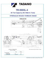
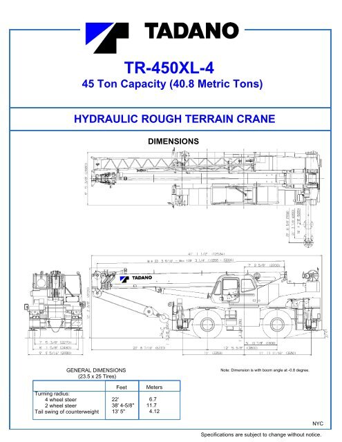
TR-450XL-4<br />
45 Ton Capacity (40.8 Me<strong>tr</strong>ic Tons)<br />
HYDRAULIC ROUGH TERRAIN CRANE<br />
GENERAL DIMENSIONS<br />
(23.5 x 25 Tires)<br />
Turning radius:<br />
4 wheel steer<br />
2 wheel steer<br />
Tail swing of counterweight<br />
Feet<br />
22'<br />
38' 4-5/8"<br />
13' 5"<br />
NEW YORK CITY<br />
DIMENSIONS<br />
Meters<br />
6.7<br />
11.7<br />
4.12<br />
Note: Dimension is with boom angle at -0.8 degree.<br />
NYC<br />
Specifications are subject to change without notice.
CRANE SPECIFICATIONS<br />
BOOM * Maximum permissible line pull may be affected by wire rope<br />
Four section full power synchronized telescoping boom,<br />
33.5'~108.3' (10.2m~33m), of round hexagonal box cons<strong>tr</strong>uction<br />
S<strong>tr</strong>ength.<br />
with four sheaves, 15-5/8" (0.396m) root diameter, at boom head. WIRE ROPE - Warrington seal wire, ex<strong>tr</strong>a improved plow steel,<br />
The synchronization system consists of a double acting telescope preformed, independent wire rope core, right regular lay.<br />
cylinder, two extension cables and re<strong>tr</strong>action cables. Hydraulic<br />
cylinder fitted with holding valve. Two easily removable wire rope<br />
3/4"(19 mm) 6X37 class<br />
guards, rope dead end provided on both sides of boom head.<br />
Boom telescope sections are supported by wear pads both<br />
HOOK BLOCKS<br />
vertically and horizontally. 45 ton (40.8 me<strong>tr</strong>ic ton) - 4 sheaves with swivel hook and<br />
safety latch, for 3/4"(19mm) wire rope. (OPTIONAL)<br />
BOOM ELEVATION - By a double acting hydraulic cylinder 25 ton (22.6 me<strong>tr</strong>ic ton) - 2 sheaves with swivel hook and<br />
with holding valve. Elevation -0.8 o ~80 o , combination con<strong>tr</strong>ols for safety latch, for 3/4"(19mm) wire rope. (OPTIONAL)<br />
hand or foot operation. Boom angle indicator.<br />
JIB - Double stage lattice type, 5<br />
5.5 ton (5.0 me<strong>tr</strong>ic ton) - Weighted hook with swivel and<br />
safety latch, for 3/4"(19mm) wire rope.<br />
o , 25 o or 45 o offset (tilt type).<br />
Single sheave, 15-5/8"(0.396m) root diameter, at base and top<br />
jib head. Stored alongside base boom section. Jib length is<br />
28.9' (8.8m) or 50' (15.2m). Self stowing jib mounting pins.<br />
HYDRAULIC SYSTEM<br />
PUMPS - Two variable piston pumps for crane functions.<br />
AUXILIARY LIFTING SHEAVE (SINGLE TOP) (OPTIONAL) - Tandem gear pump for steering, swing and optional equipment.<br />
Single sheave, 17-5/16"(0.44m) root diameter. Mounted to main Powered by carrier engine. Pump disconnect for crane is<br />
boom head for single line work (stowable). engaged/ disengaged by rotary switch from operator's cab.<br />
ANTI-TWO BLOCK - Pendant type over-winding cut out CONTROL VALVES - Multiple valves actuated by pilot<br />
device with audio-visual (FAILURE lamp/BUZZER) warning pressure with integral pressure relief valves.<br />
system.<br />
RESERVOIR - 148 gallon (560 lit.) capacity. External sight<br />
level gauge.<br />
SWING<br />
Hydraulic axial piston motor driven through planetary swing FILTRATION - 26 micron return filter, full flow with bypass<br />
speed reducer. Continuous 360 o full circle swing on ball bearing protection, located inside of hydraulic reservoir. Accessible for<br />
turntable at 2.7rpm. Equipped with manually locked/released easy replacement.<br />
swing brake. A 360 o positive swing lock for pick and carry<br />
and <strong>tr</strong>avel modes, manually engaged in cab. Twin swing OIL COOLER - Air cooled fan type.<br />
System: Free swing or lock swing con<strong>tr</strong>olled by selector switch<br />
on right hand of front console.<br />
CAB AND CONTROLS<br />
HOIST<br />
Both crane and drive operations can be performed from one<br />
MAIN HOIST - Variable speed type with grooved drum driven cab mounted on rotating supers<strong>tr</strong>ucture.<br />
by hydraulic axial piston motor through winch speed reducer.<br />
Power load lowering and raising. Equipped with automatic Left side, 1 man type, steel cons<strong>tr</strong>uction with sliding door<br />
brake (neu<strong>tr</strong>al brake) and counterbalance valve. Con<strong>tr</strong>olled access and safety glass windows opening at side. Door<br />
independently of auxiliary hoist. Equipped with cable follower window is powered con<strong>tr</strong>ol. Windshield glass window and roof<br />
and drum rotation indicator. glass window are shatter-resistant. Tilt-telescoping steering<br />
wheel. Adjustable con<strong>tr</strong>ol lever stands for swing, boom hoist,<br />
DRUM - Grooved 15-3/4"(0.40m) root diameter x 22-3/4" boom telescoping, auxiliary hoist and main hoist. Con<strong>tr</strong>ol lever<br />
(0.578m) wide. Wire rope: 597' of 3/4"diameter rope (182m of stands can change neu<strong>tr</strong>al positions and tilt for easy access to<br />
19mm). Drum capacity: 905' (276m) 6 layers. Maximum line cab. Engine throttle knob. Foot ope<strong>rated</strong> con<strong>tr</strong>ols: boom hoist,<br />
pull (permissible): 14,272lbs. (6,474kg)*. Maximum line speed: boom telescoping, service brake and engine throttle. Hot water<br />
534FPM (163m/min). cab heater and air conditioning (OPTIONAL).<br />
AUXILIARY HOIST (OPTIONAL) - Variable speed type Dash-mounted engine start/stop, monitor lamps, cigarette<br />
with grooved drum driven by hydraulic axial piston motor lighter, drive selector switch, parking brake switch, steering<br />
through winch speed reducer. Power load lowering and mode select switch, power window switch, pump engaged/<br />
raising. Equipped with automatic brake (neu<strong>tr</strong>al brake) and disengaged switch, swing brake switch, telescoping/auxiliary<br />
counterbalance valve. Con<strong>tr</strong>olled independently of main hoist. winch select switch, ou<strong>tr</strong>igger con<strong>tr</strong>ols, free swing / lock swing<br />
Equipped with cable follower and drum rotation indicator. selector switch and ash<strong>tr</strong>ay.<br />
DRUM - Grooved 15-3/4"(0.40m) root diameter x 22-3/4" Ins<strong>tr</strong>uments - Torque converter oil temperature, engine water<br />
(0.578m) wide. Wire rope: 345' of 3/4"diameter rope (105m of temperature, air pressure, fuel, speedometer, tachometer and<br />
19mm). Drum capacity: 905' (276m) 6 layers. Maximum line hour meter. Hydraulic oil pressure is monitored and displayed<br />
pull (permissible): 14,272lbs. (6,474kg)*. Maximum line speed: on the AML-L display panel.<br />
534FPM (163m/min).<br />
2 NYC
<strong>Tadano</strong> elec<strong>tr</strong>onic LOAD MOMENT INDICATOR system Operator's right hand console includes <strong>tr</strong>ansmission gear<br />
(AML-L) including: selector and sight level bubble. Upper console includes<br />
h Con<strong>tr</strong>ol lever lockout function working light switch, roof washer and wiper switch, oil<br />
h Load radius / boom angle / tip height / swing range cooler switch, emergency ou<strong>tr</strong>igger set up key switch<br />
preset function and air conditioning con<strong>tr</strong>ol switch. Swing lock lever and<br />
h Warning buzzer 3 way adjustable seat with high back and seat belt.<br />
h Boom angle / boom length / jib offset angle / load<br />
radius / <strong>rated</strong> <strong>lifting</strong> <strong>capacities</strong> / actual loads read out<br />
h Ratio of actual load moment to <strong>rated</strong> load moment NOTE: Each crane motion speed is based on unladen<br />
indication conditions.<br />
h Automatic Speed Reduction and Soft Stop function<br />
on boom elevation and/or swing.<br />
h Working condition register switch<br />
h External warning lamp<br />
TADANO AML-L monitors ou<strong>tr</strong>igger extended length and<br />
automatically programs the corresponding "RATED LIFTING<br />
CAPACITIES" table.<br />
CARRIER SPECIFICATIONS<br />
SUSPENSION - Front: Semi-elliptic leaf springs with hydraulic<br />
TYPE - Rear engine, left hand steering, 4x2 front drive or lockout device. Rear: Semi-elliptic leaf springs with hydraulic<br />
4x4 front and rear drive, selected by 2-way manual switch. lockout device.<br />
FRAME - High tensile steel, all welded mono-box cons<strong>tr</strong>uction. BRAKE SYSTEMS - Service: Air over hydraulic disc brakes on<br />
all 4 wheels. Parking/Emergency: Spring applied-air released<br />
TRANSMISSION - Elec<strong>tr</strong>onically con<strong>tr</strong>olled full automatic brake acting on input shaft of front axle. Auxiliary: Elec<strong>tr</strong>o<strong>tr</strong>ansmission.<br />
Torque converter driving full powershift with pneumatic ope<strong>rated</strong> exhaust brake.<br />
driving axle selector. 6 forward and 2 reverse speeds, constant<br />
mesh. TIRES - 23.5-25 20PR(OR)<br />
4 speeds - high range - 2 wheel drive; 4 wheel drive<br />
4 speeds - low range - 4 wheel drive OUTRIGGERS - Four hydraulic beam and jack ou<strong>tr</strong>iggers.<br />
Vertical jack cylinders equipped with integral holding valve. Each<br />
TRAVEL SPEED - 30 mph (48 km/h) ou<strong>tr</strong>igger beam and jack is con<strong>tr</strong>olled independently from cab.<br />
Beams extend to 22'11-5/8" (7.0 m) center-line and re<strong>tr</strong>act to<br />
AXLE - Front: Full floating type, steering and driving axle with within 9' 10-1/8" (3.0 m) overall width with floats. Ou<strong>tr</strong>igger jack<br />
planetary reduction. Rear: Full floating type, steering and driving floats are attached thus eliminating the need to manually<br />
axle with planetary reduction and non-spin rear differential. attach and detach them. Con<strong>tr</strong>ols and sight bubble located in<br />
supers<strong>tr</strong>ucture cab. Three ou<strong>tr</strong>igger extension lengths are<br />
STEERING- Hydraulic power steering con<strong>tr</strong>olled by steering provided with corresponding "RATED LIFTING CAPACITIES" for<br />
wheel. Three steering modes available: 2 wheel front, 4 wheel crane duty in confined areas.<br />
coordinated and 4 wheel crab. Mid. Extension 16' 4-7/8" center to center<br />
Mid. Extension 21' 3-7/8" center to center<br />
Max. extension 22' 11-5/8" center to center<br />
ENGINE<br />
Model Mitsubishi 6D16-TLEE Radiator Fin and tube core, thermostat con<strong>tr</strong>olled<br />
Type Direct injection diesel Fan, in.(mm) Suction type, 6-blade, 23.6 (600) dia.<br />
No. of cylinders 6 Starting 24 volt<br />
Combustion 4 cycle, turbo charged and after cooled Charging 24 volt system, negative ground<br />
BoreXS<strong>tr</strong>oke, in.(mm) 4.646 X 4.528 (118X115) Battery 2-120 amp. Hour<br />
Displacement, cu. in (liters) 460 (7.545) Compressor, air, CFM(l /min) 9.2 CFM (260) at 2,800rpm<br />
Air inlet heater 24 volt preheat Horsepower (kW) Gross 223 (166) at 2,700rpm<br />
Air cleaner Dry type, replaceable element Torque, Max. ft-lb (kgm) 521 (72) at 1,300rpm<br />
Oil filter Full flow with replaceable element Capacity, gal.(liters)<br />
Fuel filter Full flow with replaceable element Cooling water 3.4 (13)<br />
Fuel tank, gal.(liters) 79.2 (300), right side of carrier Lubrication 3.7 ~ 4.2 (14 ~ 16)<br />
Cooling Liquid pressurized, recirculating by-pass Fuel 79.2 (300)<br />
3 NYC
STANDARD EQUIPMENT<br />
- Four section full power synchronized boom 33.5'~108.3' - Tinted safety glass<br />
(10.2 m~33 m) - Front windshield wiper and washer<br />
- 28.9'~50' (8.8 m~15.2 m) bi-fold lattice jib (tilt type) - Roof window wiper and washer<br />
with 5 o , 25 o or 45 o pinned offsets and self storing pins. - Power window (door of the cab)<br />
- Boom hoist foot con<strong>tr</strong>ol - Rear view mirrors (right and left side)<br />
- Boom telescoping foot con<strong>tr</strong>ol - Mirror for main and auxiliary hoists<br />
- Boom angle indicator - 3 way adjustable cloth seat with high back and seat belt<br />
- Variable speed main hoist with grooved drum, cable follower - Tilt-telescoping steering wheel<br />
and 597' of 3/4" cable. - Self centering finger con<strong>tr</strong>ol levers with pilot con<strong>tr</strong>ol<br />
- Drum rotation indicator (thumper type) main hoist - Cab floor mat<br />
- <strong>Tadano</strong> twin swing system - Cigarette lighter<br />
- 360 o positive swing lock - Elec<strong>tr</strong>ic fan in cab<br />
- 4 X 4 X 4 drive/steer - Back-up alarm<br />
- Disc brakes - Low oil pressure/high water temp. warning device (visual)<br />
- Semi-elliptic leaf springs suspension with hydraulic lockout device - Rear steer centering light<br />
(front and rear) - Fenders<br />
- Non-spin rear differential - Air cleaner dust indicator<br />
- 23.5-25 20PR (OR) tires - Towing hooks-front and rear<br />
- Independently con<strong>tr</strong>olled ou<strong>tr</strong>iggers - Lifting eyes<br />
- Three ou<strong>tr</strong>igger extension positions - Tool storage compartment<br />
- Self-storing ou<strong>tr</strong>igger pads - Full ins<strong>tr</strong>umentation package<br />
- Ou<strong>tr</strong>igger extension length detector - Pump disconnect in operator's cab<br />
- Ou<strong>tr</strong>igger hose protection - Air dryer<br />
- Mitsubishi 6D16-TLEE turbo charged after cooled engine - Water separator with filter<br />
(223HP) with exhaust brake - Complete highway light package<br />
- Elec<strong>tr</strong>onic con<strong>tr</strong>olled automatic <strong>tr</strong>ansmission driven by torque - Flood lights and work lights<br />
converter - Tire inflation kit<br />
- Engine over-run alarm - Hydraulic oil cooler<br />
- Anti-Two block device (overwind cutout) - 24 volt elec<strong>tr</strong>ic system<br />
- Elec<strong>tr</strong>onic crane monitoring system - 5.5 ton (5.0 me<strong>tr</strong>ic ton) hook with swivel<br />
- <strong>Tadano</strong> elec<strong>tr</strong>onic load moment indicator system (AML-L) - Hook block tie down (front bumper)<br />
including<br />
- Con<strong>tr</strong>ol lever lockout function<br />
- Weighted hook storage compartment<br />
- Load radius / boom angle / tip height / swing range<br />
preset function<br />
- Warning buzzer<br />
OPTIONAL EQUIPMENT<br />
- Boom angle / boom length / jib offset angle / load radius / - Variable speed auxiliary hoist with grooved drum, cable<br />
<strong>rated</strong> <strong>lifting</strong> <strong>capacities</strong> / actual loads read out follower, drum rotation indicator and 345' of 3/4" cable.<br />
- Automatic Speed Reduction and Soft Stop function - Auxiliary <strong>lifting</strong> sheave (single top) stowable<br />
on boom elevation and/or swing. - 45 ton (40.8 me<strong>tr</strong>ic ton) 4 sheave hook block<br />
- Ratio of actual load moment to <strong>rated</strong> load moment indication - 25 ton (22.6 me<strong>tr</strong>ic ton) 2 sheave hook block<br />
- Working condition register switch - Hot water cab heater and air conditioner<br />
- External warning lamp - Propane heater (less tank)<br />
HOISTING SPECIFICATIONS<br />
LINE SPEEDS AND PULLS DRUM WIRE ROPE CAPACITIES<br />
Line speeds<br />
F.P.M m/min Lbs. kgf Lbs. kgf<br />
Main and auxiliary drum grooved lagging<br />
Feet Meters Feet Meters<br />
High 367 112 15,698 7,121 14,272 6,474 123.0 37.5 123.0 37.5<br />
High 400 122 14,647 6,644 13,315 6,040 134.2 40.9 257.2 78.4<br />
High 433 132 13,520 6,133 12,292 5,576 145.3 44.3 402.5 122.7<br />
High 466 142 12,557 5,696 11,417 5,179 156.5 47.7 559.0 170.4<br />
High 502 153 11,721 5,317 10,657 4,834 167.7 51.1 726.7 221.5<br />
High 534 163 10,989 4,985 9,991 4,532 178.8 54.5 905.5 276.0<br />
2 Line pulls<br />
Available<br />
3/4" (19mm) wire rope<br />
1<br />
Permissible 4<br />
Layer Speed<br />
Main or auxiliary hoist - 15'-3/4" (0.4m) drum<br />
Wire<br />
rope<br />
layer<br />
Rope per layer Total wire rope<br />
1st<br />
2<br />
3rd<br />
3<br />
4<br />
5th<br />
6th 3<br />
1<br />
2nd<br />
4th<br />
5<br />
6<br />
1 Developed by machinery with first layer of wire rope, but not based DRUM DIMENSIONS<br />
on rope s<strong>tr</strong>ength or other limitation in machinery or equipment. Inch mm<br />
2 Line speeds based only on hook block, not loaded. Root diameter 15-3/4" 400<br />
3 Sixth layer of wire rope is not recommended for hoisting Length 22-3/4" 578<br />
operations. Flange diameter 25-3/8" 645<br />
4 Permissible line pull may be affected by wire rope s<strong>tr</strong>ength.<br />
4 NYC
TR-450XL-4 WORKING RANGE CHART<br />
Axis of Rotation<br />
Load radius from Axis of Rotation in Feet<br />
NOTE: Boom and jib geome<strong>tr</strong>y shown are for unloaded condition and machine standing level on firm<br />
supporting surface. Boom deflection and subsequent radius and boom angle change must be<br />
accounted for when applying load to hook.<br />
5<br />
Lifting Height in Feet
TR-450XL-4 RATED LIFTING CAPACITIES (IN POUNDS)<br />
B<br />
A 33.5' 46' 58' 71' 83' 96' 108.3'<br />
(10.2m) (14.02m) (17.68m) (21.64m) (25.3m) (29.26m) (33.0m)<br />
10' 90,000 44,100 44,100 41,000<br />
12' 77,000 44,100 44,100 41,000 36,600 R W R W R W R W R W R W<br />
15' 67,200 44,100 44,100 41,000 36,600 30,400 80 o<br />
19.0 9,900 28.5 8,150 35.4 6,000 24.9 5,900 40.7 4,000 52.8 2,850<br />
20' 52,700 44,100 42,700 36,400 31,100 27,500 20,000 75 o<br />
31.5 9,900 40.0 7,200 46.9 5,700 39.4 5,900 54.5 3,500 65.3 2,550<br />
25' 36,500 43,000 37,500 32,000 26,900 23,700 20,000 70 o<br />
43.6 8,600 51.5 6,300 57.4 5,300 52.8 4,900 67.3 3,100 76.8 2,400<br />
30' 29,800 30,200 28,600 23,600 20,700 19,100 65 o<br />
55.1 6,900 62.3 5,500 67.3 4,850 65.9 4,100 79.4 2,850 87.6 2,300<br />
35' 22,300 22,700 23,000 20,900 18,400 16,700 60 o<br />
65.9 5,800 72.5 4,800 76.4 4,400 78.4 3,500 90.9 2,650 97.4 2,200<br />
40' 18,000 18,300 18,500 16,400 14,700 55 o<br />
76.1 4,900 82.0 4,150 85.3 3,950 90.2 3,000 101.1 2,350 106.6 2,100<br />
45' 14,500 14,800 14,900 14,800 13,200 50 o<br />
85.6 3,750 90.6 3,300 93.2 3,100 100.7 2,450 110.6 2,150 114.5 1,950<br />
50' 11,900 12,100 12,300 12,450 11,900 45 o<br />
94.2 2,900 98.4 2,500 100.1 2,300 110.6 1,750 119.1 1,500 121.7 1,400<br />
55' 10,150 10,400 10,500 10,500 40 o<br />
101.7 2,200 105.3 1,900 119.4 1,200 126.6 1,100<br />
60' 8,550 8,750 8,750 8,900 35 o<br />
108.6 1,650 111.6 1,500 127.6 800 133.2 800<br />
65' 7,500 7,550 7,600 30 o<br />
114.8 1,250 117.1 1,150<br />
70' 6,300 6,400 6,500 25 o<br />
360<br />
Boom<br />
Angle<br />
108.3' (33.0m) Boom + 28.9' (8.8m) Jib<br />
in<br />
Degree<br />
119.8 900 121.7 900<br />
75' 5,400 5,500 5,600<br />
80' 4,600 4,850 A: Boom length in feet<br />
85' 4,000 4,100 B: Load radius in feet<br />
90' 3,400 C: Minimum boom angle (deg.) for indicated length (no load)<br />
95' 2,950 R: Load radius in feet<br />
100' 2,500 W: Rated <strong>lifting</strong> capacity in pounds<br />
C<br />
o ON OUTRIGGERS FULLY EXTENDED 22'11-5/8'' (7.0m) SPREAD<br />
ROTATION<br />
108.3' (33.0m) Boom + 50.0' (15.2m) Jib<br />
5 o offset 25 o offset 45 o offset 5 o offset 25 o offset 45 o offset<br />
0 o<br />
B<br />
A 33.5' 46' 58' 71' 83' 96' 108.3'<br />
(10.2m) (14.02m) (17.68m) (21.64m) (25.3m) (29.26m) (33.0m)<br />
10' 90,000 44,100<br />
12' 77,000 44,100<br />
44,100<br />
44,100<br />
41,000<br />
41,000 36,600 R W R W R W R W R W R W<br />
15' 67,200 44,100 44,100 41,000 36,600 30,400 80 o<br />
19.0 9,900 28.5 8,150 35.4 6,000 24.9 5,900 40.7 4,000 52.8 2,850<br />
20' 52,700 44,100 42,700 36,400 31,100 27,500 20,000 75 o<br />
31.5 9,900 40.0 7,200 46.9 5,700 39.4 5,900 54.5 3,500 65.3 2,550<br />
25' 33,800 35,300 36,000 32,000 26,900 23,700 20,000 70 o<br />
43.6 8,600 51.5 6,300 57.4 5,300 52.8 4,900 67.3 3,100 76.8 2,400<br />
30' 24,800 25,400 25,600 23,600 20,700 19,100 65 o<br />
55.1 6,750 62.3 5,500 67.3 4,850 65.9 4,100 79.4 2,850 87.6 2,300<br />
35' 18,600 18,900 19,300 19,400 18,400 16,700 60 o<br />
65.9 4,700 72.5 3,800 76.4 4,150 78.4 3,400 90.9 2,650 97.4 2,200<br />
40' 14,900 15,200 15,400 15,400 14,700 55 o<br />
76.1 3,200 82.0 2,800 85.3 2,950 90.2 2,150 101.1 1,800 106.6 1,650<br />
45' 11,900 12,200 12,300 12,500 12,500 50 o<br />
85.6 2,100 90.6 1,850 93.2 2,000 100.7 1,200 110.6 1,050 114.5 1,000<br />
50' 9,700 9,900 10,100 10,200 10,300 45 o<br />
94.2 1,350 98.4 1,100 100.1 1,250<br />
55' 8,300 8,300 8,500 8,600 40 o<br />
45<br />
101.7 800<br />
60' 6,800 7,000 7,200 7,200<br />
65' 5,800 5,900 6,000<br />
70' 4,900 5,000 5,000<br />
75' 4,100 4,100 4,200<br />
80' 3,500 3,500<br />
85' 2,900 2,900 A: Boom length in feet<br />
90' 2,400 B: Load radius in feet<br />
95' 1,900 C: Minimum boom angle (deg.) for indicated length (no load)<br />
100' 1,700 R: Load radius in feet<br />
C W: Rated <strong>lifting</strong> capacity in pounds<br />
o offset<br />
0 o<br />
ON OUTRIGGERS MID. EXTENDED 21' 3-7/8"(6.5m) SPREAD<br />
360 o ROTATION<br />
Boom<br />
Angle<br />
108.3' (33.0m) Boom + 28.9' (8.8m) Jib 108.3' (33.0m) Boom + 50.0' (15.2m) Jib<br />
in<br />
Degree<br />
5 o offset 25 o offset 45 o offset 5 o offset 25 o offset<br />
6 NYC
TR-450XL-4 RATED LIFTING CAPACITIES (IN POUNDS)<br />
C<br />
17 o<br />
33 o<br />
0 o<br />
2,450<br />
40' 9,800 10,000 10,100 10,300 10,300 55 1,300<br />
45' 7,600 7,900 8,100 8,200 8,200<br />
50' 6,000 6,200 6,400 6,500 6,600<br />
5,300<br />
60' 3,800 4,000 4,100 4,200<br />
3,200 3,300 3,400<br />
70' 2,400 2,500 2,600<br />
75' 1,900 2,000 2,000<br />
1,500 1,500<br />
o<br />
4,150<br />
35' 12,000 12,500 12,800 12,900 13,100 13,200 60 o<br />
30' 16,200 16,600 17,100 17,200 17,300 17,300 65 o<br />
15' 57,000 44,100 44,100 41,000 36,600 30,400 80<br />
20' 33,200 34,900 35,400 35,900 31,100 27,500 20,000<br />
25' 21,400 22,700 23,200 23,600 23,900 23,700 20,000<br />
o<br />
ON OUTRIGGERS MID. EXTENDED 16' 4-7/8"(5.0m) SPREAD<br />
360<br />
B (10.2m) (14.02m)(17.68m)(21.64m) (25.3m) (29.26m) (33.0m)<br />
10' 90,000 44,100 44,100 41,000<br />
12' 77,000 44,100 44,100 41,000 36,600<br />
o ROTATION<br />
A 33.5' 46' 58' 71' 83' 96' 108.3'<br />
70 o<br />
Boom<br />
Angle<br />
108.3' (33.0m) Boom + 28.9' (8.8m) Jib<br />
in<br />
Degree<br />
75<br />
55.1<br />
65.9<br />
76.1<br />
o<br />
55'<br />
5,000 5,100 5,200<br />
65'<br />
80'<br />
Boom length in feet<br />
33.5' (10.2m)<br />
46' (14.02m)<br />
58' (17.68m)<br />
71' (21.64m)<br />
83' (25.3m)<br />
96' (29.26m)<br />
108.3' (33.0m)<br />
NOTE: Load radiuses for jib operation are given for reference with the boom fully extended to 108.3' (33m).<br />
4,700 lbs. (2,132 kg) shall be sub<strong>tr</strong>acted from the <strong>rated</strong> <strong>lifting</strong> capacity of main boom, when 28.9'<br />
jib is attached to main boom head. 28.9' jib weight is 1,250 lbs. (567 kg).<br />
6,600 lbs. (3,000 kg) shall be sub<strong>tr</strong>acted from the <strong>rated</strong> <strong>lifting</strong> capacity of main boom, when 50.0'<br />
jib is attached to main boom head. 50.0' jib weight is 1,780 lbs. (807 kg).<br />
Standard number of parts of line for ou<strong>tr</strong>igger operation should be according to the following table.<br />
Boom Length in Feet<br />
(meters)<br />
33.5'<br />
33.5' to 71' 71' to 108.3' Single top<br />
(10.2) (10.2 to 21.64) (21.64 to 33.0) Jib<br />
Number of parts of line 8 6 4<br />
5<br />
W R W R W R W R W R W<br />
19.0 9,900 28.5 8,150 35.4 6,000 24.9 5,900 40.7 4,000 52.8 2,850<br />
31.5 9,900 40.0 7,200 46.9 5,700 39.4 5,900 54.5 3,500 65.3 2,550<br />
6,900 51.5 5,800 57.4 5,150 52.8 4,900 67.3 3,100 76.8 2,400<br />
o offset 25 o offset 45 o 5 offset<br />
43.6<br />
o offset 25 o offset 45 o offset<br />
R<br />
62.3 3,650 67.3 3,400 65.9 2,850 79.4 2,150 87.6 2,000<br />
72.5 2,150 76.4 2,000 78.4 1,450 90.9 1,100 97.4 950<br />
82.0 1,150 85.3 1,100<br />
A: Boom length in feet<br />
B: Load radius in feet<br />
C: Minimum boom angle (deg.) for indicated length (no load)<br />
R: Load radius in feet<br />
W: Rated <strong>lifting</strong> capacity in pounds<br />
The <strong>lifting</strong> capacity data stored in the LOAD MOMENT INDICATOR (AML-L) is based on the standard number of parts of<br />
line listed in the chart.<br />
Maximum <strong>lifting</strong> capacity is res<strong>tr</strong>icted by the number of parts of line of LOAD MOMENT INDICATOR (AML-L).<br />
1<br />
108.3' (33.0m) Boom + 50.0' (15.2m) Jib<br />
7 NYC
WARNING AND OPERATING INSTRUCTIONS<br />
FOR LIFTING CAPACITIES<br />
GENERAL 10. When making lifts at a load radius not shown, use the next<br />
1. RATED LIFTING CAPACITIES apply only to the machine as longer radius to determine allowable capacity.<br />
originally manufactured and normally equipped by TADANO 11. Load per line should not exceed 11,500 lbs. (5,200kg) for main<br />
LTD. Modifications to the machine or use of optional winch and 11,000 lbs. (5,000kg) for auxiliary winch.<br />
equipment other than that specified can result in a reduction 12. Check the actual number of parts of line with LOAD MOMENT<br />
of capacity. INDICATOR (AML-L) before operation. Maximum <strong>lifting</strong><br />
2. Cons<strong>tr</strong>uction equipment can be hazardous if improperly capacity is res<strong>tr</strong>icted by the number of parts of line of LOAD<br />
ope<strong>rated</strong> or maintained. Operation and maintenance of this MOMENT INDICATOR (AML-L). Limited capacity is as<br />
machine must be in compliance with information in the determined from the formula, Single line pull for main winch<br />
operation, safety and maintenance manual supplied with (11,500 lbs.) x number of parts of line.<br />
machine. If these manuals are missing, order replacement 13. The boom angle before loading should be greater to account<br />
through the dis<strong>tr</strong>ibutor. for deflection.<br />
3. The operator and other personnel associated with this 14. The 33.5' (10.2m) boom length <strong>capacities</strong> are based on boom<br />
machine shall fully acquaint themselves with the latest fully re<strong>tr</strong>acted. If not fully re<strong>tr</strong>acted [less than 46' (14.0m)<br />
<strong>America</strong>n National Standards Institute (ANSI) safety boom length], use the <strong>rated</strong> <strong>lifting</strong> <strong>capacities</strong> for the 46' (14.0m)<br />
standards for cranes. boom length.<br />
15. Extension or re<strong>tr</strong>action of the boom with loads may be<br />
SET UP attempted within the limits of the RATED LIFTING CAPACITIES.<br />
1. Rated <strong>lifting</strong> <strong>capacities</strong> on the chart are the maximum The ability to telescope loads is limited by hydraulic pressure,<br />
allowable crane <strong>capacities</strong> and are based on the machine boom angle, boom length, crane maintenance, etc.<br />
standing level on firm supporting surface under ideal job 16. For <strong>lifting</strong> capacity of single top, reduce the <strong>rated</strong> <strong>lifting</strong><br />
conditions. Depending on the nature of the supporting <strong>capacities</strong> of relevant boom by the mass of the main hook<br />
surface, it may be necessary to have s<strong>tr</strong>uctural supports block. Capacities of single top shall not exceed 11,000 lbs.<br />
under the ou<strong>tr</strong>igger floats or tires to spread the loads to a (5,000kg) including main hook.<br />
larger bearing surface. 17. When erecting and stowing jib, be sure to retain it by hand or by<br />
2. For ou<strong>tr</strong>igger operation, ou<strong>tr</strong>iggers shall be properly extended other means to prevent its free movement.<br />
with tires free of supporting surface before operating crane. 18. 4,700 lbs. (2,132 kg) shall be sub<strong>tr</strong>acted from the <strong>rated</strong> <strong>lifting</strong><br />
<strong>capacities</strong> of the main boom, when 28.9' jib is attached to main<br />
OPERATION boom head. 28.9' jib weight is 1,250 lbs. (567 kg).<br />
1. Rated <strong>lifting</strong> <strong>capacities</strong> have been tested to and meet 6,600 lbs. (3,000 kg) shall be sub<strong>tr</strong>acted from the <strong>rated</strong> <strong>lifting</strong><br />
minimum requirements of SAE J1063-Cantilevered Boom <strong>capacities</strong> of the main boom, when 50.0' jib is attached to main<br />
Crane S<strong>tr</strong>uctures Method of Test. boom head. 50.0' jib weight is 1,780 lbs. (807 kg).<br />
2. Rated <strong>lifting</strong> <strong>capacities</strong> do not exceed 85 % of the tipping 19. Use Anti-two block (OVERWIND CUTOUT) disable switch<br />
load on ou<strong>tr</strong>iggers fully extended as determined by SAE when erecting and stowing jib and when stowing hook block.<br />
J765-Crane Stability Test Code. While the switch is pushed, the hoist does not stop, even when<br />
Rated <strong>lifting</strong> <strong>capacities</strong> for partially extended ou<strong>tr</strong>iggers are overwind condition occurs.<br />
determined from the formula, Rated Lifting Capacities 20. For boom length with 28.9' (8.8m) jib, <strong>rated</strong> <strong>lifting</strong> <strong>capacities</strong> are<br />
=(Tipping Load - 0.1 x Tip Reaction)/1.25. determined by loaded boom angle only in the column headed<br />
3. Rated <strong>lifting</strong> <strong>capacities</strong> above bold lines in the chart are "108.3' (33.0m) boom + 28.9' (8.8m) jib".<br />
based on crane s<strong>tr</strong>ength and those below, on its stability. For boom length with 50' (15.2 m) jib, <strong>rated</strong> <strong>lifting</strong> <strong>capacities</strong><br />
They are based on actual load radius increased by boom are determined by loaded boom angle only in the column<br />
deflection. headed "108.3' (33.0m) boom + 50' (15.2m) jib".<br />
4. The weight of load handling device such as hook blocks, For angles not shown, use the next lower loaded boom angle<br />
slings, etc., must be considered as part of the load and must to determine allowable capacity.<br />
be deducted from the <strong>lifting</strong> <strong>capacities</strong>. 21. When <strong>lifting</strong> a load by using jib (aux. winch) and boom (main<br />
5. Rated <strong>lifting</strong> <strong>capacities</strong> are based on freely suspended loads winch) simultaneously, do the following:<br />
and make no allowance for such factors as the effect of wind, h Enter the operation status as jib operation, not as boom<br />
sudden stopping of loads, supporting surface conditions, operation.<br />
inflation of tires, operating speeds, side loads, etc. Side pull h Before starting operation, make sure that mass of load is<br />
on boom or jib is ex<strong>tr</strong>emely dangerous. within <strong>rated</strong> <strong>lifting</strong> capacity for jib.<br />
6. Rated <strong>lifting</strong> <strong>capacities</strong> do not account for wind on lifted load<br />
or boom. Rated <strong>lifting</strong> <strong>capacities</strong> and boom length shall be DEFINITIONS<br />
appropriately reduced, when wind velocity is above 20 mph 1. Load Radius: Horizontal distance from a projection of the axis<br />
(9 m/sec.). of rotation to supporting surface before loading to the center of<br />
7. Rated <strong>lifting</strong> <strong>capacities</strong> at load radius shall not be exceeded. the vertical hoist line or tackle with load applied.<br />
Do not tip the crane to determine allowable loads. 2. Loaded Boom Angle: The angle between the boom base<br />
8. Do not operate at boom lengths, radii, or boom angle, where section and the horizontal, after <strong>lifting</strong> the <strong>rated</strong> <strong>lifting</strong> capacity<br />
no <strong>capacities</strong> are shown. Crane may overturn without any at the load radius.<br />
load on the hook. 3. Working Area: Area measured in a circular arc about the<br />
9. When boom length is between values listed, refer to the centerline of rotation.<br />
<strong>rated</strong> <strong>lifting</strong> <strong>capacities</strong> of the next longer and next shorter 4. Freely Suspended Load: Load hanging free with no direct<br />
booms for the same radius. The lesser of the two <strong>rated</strong> <strong>lifting</strong> external force applied except by the hoist line.<br />
<strong>capacities</strong> shall be used. 5. Side Load: Horizontal side force applied to the lifted load either<br />
on the ground or in the air.<br />
8 NYC
TR-450XL-4 RATED LIFTING CAPACITIES (IN POUNDS)<br />
A 42 o<br />
59 o<br />
0 o<br />
31 o<br />
0 o<br />
Load<br />
Radius<br />
in<br />
Feet<br />
Stationary<br />
360<br />
33.5' 58' 83' 33.5'<br />
83'<br />
(10.2m) (17.68m) (25.3m) (10.2m)<br />
(25.3m)<br />
10' 36,000<br />
12'<br />
33,000<br />
15'<br />
20'<br />
19,500 15,400<br />
25'<br />
14,800 14,300<br />
30' 10,600 11,000<br />
35'<br />
8,000 7,900<br />
40' 6,100 6,100<br />
45'<br />
4,500 4,500<br />
50'<br />
3,600 3,500<br />
55'<br />
2,700<br />
60'<br />
1,900<br />
o ON RUBBER<br />
Over Front<br />
Rotation<br />
Boom Length in Feet<br />
Boom Length in Feet<br />
58'<br />
(17.68m)<br />
24,000<br />
33,000<br />
16,500 20,000<br />
28,600 27,000<br />
9,800 12,300<br />
21,200<br />
5,500 7,000 8,100<br />
13,700<br />
3,000 4,300 5,100<br />
2,800 3,200<br />
1,500 1,800<br />
Boom length in feet Working area<br />
NOTE:<br />
33.5' (10.2m)<br />
58' (17.68m)<br />
83' (25.3m)<br />
A : Minimum boom angle (deg.) for indicated length (no load)<br />
Approx. 2 o<br />
Standard number of parts of line for on rubber operation should be according to the following table.<br />
The <strong>lifting</strong> capacity data stored in the LOAD MOMENT INDICATOR (AML-L) is based on the standard number<br />
of parts of line listed in the chart.<br />
Boom mode Boom Single top<br />
Number of parts of line 4 1<br />
WARNING AND OPERATING INSTRUCTIONS<br />
FOR ON RUBBER LIFTING CAPACITIES<br />
1. Rated <strong>lifting</strong> <strong>capacities</strong> on rubber are in pounds and do not exceed 6. Over front operation shall be performed within two degrees in front of<br />
75 % of tipping loads as determined by SAE J765-Crane Stability chassis.<br />
Test Code. 7. On rubber <strong>lifting</strong> with "jib" is not permitted. Maximum permissible<br />
2. Rated <strong>lifting</strong> <strong>capacities</strong> shown in the chart are based on condition boom length is 83 ft. (25.3m).<br />
that crane is set on firm level surfaces with suspension lock applied. 8. When making lift on rubber (stationary), set parking brake.<br />
Those above bold lines are based on tire capacity and those 9. For creep operation, boom must be centered over front of machine,<br />
below, on crane stability. They are based on actual load radius swing lock engaged, and load res<strong>tr</strong>ained from swinging. Travel slowly<br />
increased by tire deformation and boom deflection. and keep the lifted load as close to the ground as possible, and<br />
3. If the suspension lock cylinders contain air, the axle will not be especially avoid any abrupt steering, accelerating or braking.<br />
locked completely and <strong>rated</strong> <strong>lifting</strong> <strong>capacities</strong> may not be obtainable. 10. Do not operate the crane while carrying the load.<br />
Bleed the cylinders according to the operation safety and 11. Creep is motion for crane not to <strong>tr</strong>avel more than 200 ft. (60 m) in any<br />
maintenance manual. 30 minute period and to <strong>tr</strong>avel at the speed of less than 1 mph (1.6<br />
4. Rated <strong>lifting</strong> <strong>capacities</strong> are based on proper tire inflation, capacity km/h).<br />
and condition. Damaged tires are hazardous to safe operation of 12. For creep operation, set drive select switch to "4-WHEEL (Lo)" and<br />
crane. set gear shift lever to "1".<br />
5. Tires shall be inflated to correct air pressure.<br />
Tires Air Pressure<br />
23.5-25 20PR 68 psi. (4.75kgf/cm 2 )<br />
Over<br />
front<br />
Creep<br />
Over Front<br />
Boom Length in Feet<br />
33.5' 58' 83'<br />
(10.2m)<br />
34,000<br />
(17.68m) (25.3m)<br />
29,000 30,000<br />
24,000 25,000<br />
17,000 17,900 15,400<br />
13,000 13,300 14,300<br />
10,600 11,000<br />
8,000 7,900<br />
6,100 6,100<br />
4,500 4,500<br />
3,600 3,500<br />
2,700<br />
1,900<br />
0 o<br />
TIRE : 23.5-25 20PR<br />
360 o<br />
Rear<br />
31 o<br />
9 NYC
WARNING AND OPERATING INSTRUCTIONS<br />
FOR USING THE LOAD MOMENT INDICATOR (AML-L)<br />
1. When operating crane on ou<strong>tr</strong>iggers: h Press the boom mode select key to select the boom<br />
h Before ou<strong>tr</strong>igger operation, the suspension lock operation status that corresponds to the actual boom configuration.<br />
must be performed. Suspension lock system can only be Pay attention to the following :<br />
performed in the over-front area. (1) For stationary operation :<br />
h Push and hold the suspension lock switch to the "LOCK" h The over-front <strong>capacities</strong> are in effect only when the<br />
position until suspension lock lamp changes from flashing over-front area symbol is lit. When the swing position<br />
to a solid light and the suspension is fully re<strong>tr</strong>acted. is more than 1 o off from center of chassis (i.e., not in the<br />
(Ou<strong>tr</strong>igger and crane operations cannot be performed over-front area), 360 o <strong>rated</strong> <strong>lifting</strong> <strong>capacities</strong> are in effect.<br />
until suspension lock operation has been completed.) h Before swinging to the over-side area with a load that<br />
h Set P.T.O. switch to "ON" position. was lifted in over-front area, make sure the actual weight<br />
h Extend the ou<strong>tr</strong>iggers and level the crane. of the load is less than the 360 o <strong>rated</strong> <strong>lifting</strong> <strong>capacities</strong>.<br />
h Press the ou<strong>tr</strong>igger mode select key to register the (2) For creep operation :<br />
ou<strong>tr</strong>iggers condition with the LOAD MOMENT INDICATOR h The creep <strong>rated</strong> <strong>lifting</strong> <strong>capacities</strong> are in effect only when<br />
(AML-L). Press the register key. The ou<strong>tr</strong>igger status the over-front area symbol is lit. If swing position is not<br />
symbol will change from flashing to a solid light. in the over-front area, never creep with the load.<br />
h Press the boom mode select key to select the boom 3. The swing does not automatically stop if the crane become<br />
status that corresponds to the actual boom configuration. overloaded.<br />
Each time the boom mode select key is pressed, the 4. During crane operation, make sure that displays on the front<br />
status changes. Press the register key to register the panel of the LOAD MOMENT INDICATOR (AML-L) are in<br />
boom status with the LOAD MOMENT INDICATOR accordance with actual operating conditions.<br />
(AML-L). The boom status symbol will change from 5. The displayed values of LOAD MOMENT INDICATOR<br />
flashing to a solid light. (AML-L) are based on freely suspended loads and make no<br />
h When erecting and stowing the jib, select the "JIB SET" allowance for such factors as the effect of wind, sudden<br />
mode. (The jib state symbol will be flashing.) stopping of loads, supporting surface conditions, inflation of<br />
2. When operating crane on rubber: tires, operating speed, side loads, etc. For safe operation, it<br />
h Before ou<strong>tr</strong>igger operation, the suspension lock operation is recommended that lifted loads be appropriately reduced<br />
must be performed. Suspension lock system can only be when extending and lowering the boom or swinging.<br />
performed in the over-front area. 6. LOAD MOMENT INDICATOR (AML-L) is intended as an aid<br />
h Push and hold the suspension lock switch to the "LOCK" to the operator. Under no condition should it be relied upon<br />
position until suspension lock lamp changes from flashing to replace use of capacity charts and operating ins<strong>tr</strong>uctions.<br />
to a solid light and the suspension is fully re<strong>tr</strong>acted. Relying solely upon the LOAD MOMENT INDICATOR<br />
(Crane operations cannot be performed until suspension (AML-L) in place of good operating practice can cause an<br />
lock operation has been completed.) accident. The operator must exercise caution to assure<br />
h Set P.T.O. switch to "ON" position. safety.<br />
h Press the ou<strong>tr</strong>igger mode select key to select the on<br />
rubber status that corresponds to the actual on rubber<br />
configuration. Each time the ou<strong>tr</strong>igger mode select key is<br />
pressed, the status changes. When the stationary operation<br />
is selected, the on-rubber status symbol will be a solid light.<br />
When the creep operation is selected, the on-rubber status<br />
symbol will be a flashing light.<br />
TR-450XL-4 Axle weight dis<strong>tr</strong>ibution chart<br />
Pounds<br />
Kilograms<br />
GVW Front Rear GVW Front Rear<br />
Base machine 69,100 36,900 32,200 31,343 16,738 14,605<br />
Remove: 1. 5.5 ton (5.0 me<strong>tr</strong>ic ton) hook ball -290 -410 120 -132 -186 54<br />
2. Top jib (21') -530 -600 70 -240 -272 32<br />
3. Base jib (28.8') -1,250 -2,070 820 -567 -939 372<br />
Option: 1. Auxiliary hoist with 345' (105m) of 3/4" (19mm) 1830 -440 2,270 830 -200 1,030<br />
2. Auxiliary <strong>lifting</strong> sheave 150 390 -240 68 177 -109<br />
3. 45 ton (40.8 me<strong>tr</strong>ic ton) hook block 760 1,320 -560 345 599 -254<br />
4. 25 ton (22.6 me<strong>tr</strong>ic ton) hook block 630 1,090 -460 285 494 -209<br />
5. Hot water cab heater and air conditioner 220 70 150 100 32 68<br />
5. EXT. Counter weight -1,760 890 -2,650 -798 404 -1,202<br />
10 NYC
MEMO<br />
TADANO AMERICA CORPORATION<br />
333 NORTHPARK CENTRAL DR, SUITE Z<br />
HOUSTON, TEXAS 77073 U.S.A.<br />
PHONE: (281) 869-0030 EXT.315<br />
FAX: (281) 869-0040<br />
http://www.tadanoamerica.com/<br />
Form No. TAC-TR-450XL-04-021028NYC