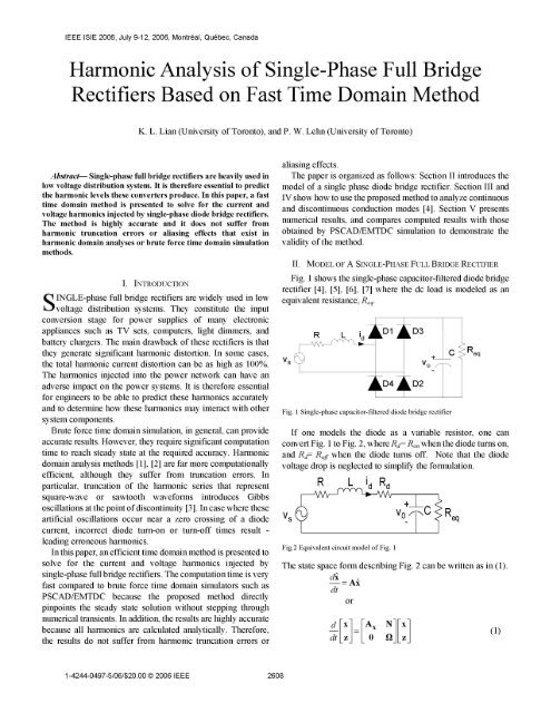
Harmonic Analysis of Single-Phase Full Bridge Rectifiers Based on ...
Harmonic Analysis of Single-Phase Full Bridge Rectifiers Based on ...
Harmonic Analysis of Single-Phase Full Bridge Rectifiers Based on ...

Create successful ePaper yourself
Turn your PDF publications into a flip-book with our unique Google optimized e-Paper software.
IEEE ISIE 2006, July 9-12, 2006, M<strong>on</strong>treal, Quebec, Canada<br />
<str<strong>on</strong>g>Harm<strong>on</strong>ic</str<strong>on</strong>g> <str<strong>on</strong>g>Analysis</str<strong>on</strong>g> <str<strong>on</strong>g>of</str<strong>on</strong>g> <str<strong>on</strong>g>Single</str<strong>on</strong>g>-<str<strong>on</strong>g>Phase</str<strong>on</strong>g> <str<strong>on</strong>g>Full</str<strong>on</strong>g> <str<strong>on</strong>g>Bridge</str<strong>on</strong>g><br />
<str<strong>on</strong>g>Rectifiers</str<strong>on</strong>g> <str<strong>on</strong>g>Based</str<strong>on</strong>g> <strong>on</strong> Fast Time Domain Method<br />
K. L. Lian (University <str<strong>on</strong>g>of</str<strong>on</strong>g> Tor<strong>on</strong>to), and P. W. Lehn (University <str<strong>on</strong>g>of</str<strong>on</strong>g> Tor<strong>on</strong>to)<br />
Abstract- <str<strong>on</strong>g>Single</str<strong>on</strong>g>-phase full bridge rectifiers are heavily used in<br />
low voltage distributi<strong>on</strong> system. It is therefore essential to predict<br />
the harm<strong>on</strong>ic levels these c<strong>on</strong>verters produce. In this paper, a fast<br />
time domain method is presented to solve for the current and<br />
voltage harm<strong>on</strong>ics injected by single-phase diode bridge rectifiers.<br />
The method is highly accurate and it does not suffer from<br />
harm<strong>on</strong>ic truncati<strong>on</strong> errors or aliasing effects that exist in<br />
harm<strong>on</strong>ic domain analyses or brute force time domain simulati<strong>on</strong><br />
methods.<br />
I. INTRODUCTION<br />
SINGLE-phase full bridge rectifiers are widely used in low<br />
voltage distributi<strong>on</strong> systems. They c<strong>on</strong>stitute the input<br />
c<strong>on</strong>versi<strong>on</strong> stage for power supplies <str<strong>on</strong>g>of</str<strong>on</strong>g> many electr<strong>on</strong>ic<br />
appliances such as TV sets, computers, light dimmers, and<br />
battery chargers. The main drawback <str<strong>on</strong>g>of</str<strong>on</strong>g> these rectifiers is that<br />
they generate significant harm<strong>on</strong>ic distorti<strong>on</strong>. In some cases,<br />
the total harm<strong>on</strong>ic current distorti<strong>on</strong> can be as high as 100%.<br />
The harm<strong>on</strong>ics injected into the power network can have an<br />
adverse impact <strong>on</strong> the power systems. It is therefore essential<br />
for engineers to be able to predict these harm<strong>on</strong>ics accurately<br />
and to determine how these harm<strong>on</strong>ics may interact with other<br />
system comp<strong>on</strong>ents.<br />
Brute force time domain simulati<strong>on</strong>, in general, can provide<br />
accurate results. However, they require significant computati<strong>on</strong><br />
time to reach steady state at the required accuracy. <str<strong>on</strong>g>Harm<strong>on</strong>ic</str<strong>on</strong>g><br />
domain analysis methods [1], [2] are far more computati<strong>on</strong>ally<br />
efficient, although they suffer from truncati<strong>on</strong> errors. In<br />
particular, truncati<strong>on</strong> <str<strong>on</strong>g>of</str<strong>on</strong>g> the harm<strong>on</strong>ic series that represent<br />
square-wave or sawtooth waveforms introduces Gibbs<br />
oscillati<strong>on</strong>s at the point <str<strong>on</strong>g>of</str<strong>on</strong>g> disc<strong>on</strong>tinuity [3]. In case where these<br />
artificial oscillati<strong>on</strong>s occur near a zero crossing <str<strong>on</strong>g>of</str<strong>on</strong>g> a diode<br />
current, incorrect diode turn-<strong>on</strong> or turn-<str<strong>on</strong>g>of</str<strong>on</strong>g>f times result -<br />
leading err<strong>on</strong>eous harm<strong>on</strong>ics.<br />
In this paper, an efficient time domain method is presented to<br />
solve for the current and voltage harm<strong>on</strong>ics injected by<br />
single-phase full bridge rectifiers. The computati<strong>on</strong> time is very<br />
fast compared to brute force time domain simulators such as<br />
PSCAD/EMTDC because the proposed method directly<br />
pinpoints the steady state soluti<strong>on</strong> without stepping through<br />
numerical transients. In additi<strong>on</strong>, the results are highly accurate<br />
because all harm<strong>on</strong>ics are calculated analytically. Therefore,<br />
the results do not suffer from harm<strong>on</strong>ic truncati<strong>on</strong> errors or<br />
1-4244-0497-5/06/$20.00 © 2006 IEEE 2608<br />
aliasing effects.<br />
The paper is organized as follows: Secti<strong>on</strong> II introduces the<br />
model <str<strong>on</strong>g>of</str<strong>on</strong>g> a single phase diode bridge rectifier. Secti<strong>on</strong> III and<br />
IV show how to use the proposed method to analyze c<strong>on</strong>tinuous<br />
and disc<strong>on</strong>tinuous c<strong>on</strong>ducti<strong>on</strong> modes [4]. Secti<strong>on</strong> V presents<br />
numerical results, and compares computed results with those<br />
obtained by PSCAD/EMTDC simulati<strong>on</strong> to dem<strong>on</strong>strate the<br />
validity <str<strong>on</strong>g>of</str<strong>on</strong>g> the method.<br />
II. MODEL OF A SINGLE-PHASE FULL BRIDGE RECTIFIER<br />
Fig. 1 shows the single-phase capacitor-filtered diode bridge<br />
rectifier [4], [5], [6], [7] where the dc load is modeled as an<br />
equivalent resistance, Req,<br />
VS<br />
R L idi<br />
LD1I<br />
LD4<br />
LD3<br />
DD2<br />
Fig. I <str<strong>on</strong>g>Single</str<strong>on</strong>g>-phase capacitor-filtered diode bridge rectifier<br />
C Req<br />
If <strong>on</strong>e models the diode as a variable resistor, <strong>on</strong>e can<br />
c<strong>on</strong>vert Fig. 1 to Fig. 2, where Rd= R<strong>on</strong> when the diode turns <strong>on</strong>,<br />
and Rd- Rff when the diode turns <str<strong>on</strong>g>of</str<strong>on</strong>g>f. Note that the diode<br />
voltage drop is neglected to simplify the formulati<strong>on</strong>.<br />
Vs<br />
Fig.2 Equivalent circuit model <str<strong>on</strong>g>of</str<strong>on</strong>g> Fig. I<br />
Req<br />
The state space form describing Fig. 2 can be written as in (1).<br />
di = Ax<br />
dt<br />
or<br />
dFX1 FAx N1Fx<br />
dtLzL ° QiLzi<br />
(1)
-(R + Rd)<br />
where x = [id Vo IT Ax = L<br />
I<br />
0<br />
N=0 N L L ~~... L<br />
ii<br />
L<br />
-1I<br />
ReqC<br />
z =uxi uy1 ux2 uy2 |u uyn and<br />
Q= blkdiag {K? 0 0}[2? 0 0'[n j}<br />
Note that:<br />
1. A is a time varying matrix because Rd changes its values<br />
depending <strong>on</strong> the diodes' c<strong>on</strong>ducting or n<strong>on</strong>-c<strong>on</strong>ducting<br />
states. To distinguish these two cases, A,,. and A0ff will be<br />
used to denote Rd= R<strong>on</strong> and Rd= Ro,^ respectively.<br />
2. The source voltage, v, is assumed to take the following<br />
n<br />
general form: vs = E Ak sin(kt + bk) .<br />
k=I<br />
3. uxk and uyk represents a pair <str<strong>on</strong>g>of</str<strong>on</strong>g> kth harm<strong>on</strong>ic oscillator states,<br />
where the source voltage may be expressed in terms <str<strong>on</strong>g>of</str<strong>on</strong>g> these<br />
n<br />
states according to: vS = E uyk, provided that the states, uxk<br />
k=I<br />
and uyk are initialized at Akcos(o), and Aksin(o), respectively.<br />
4. A more involved modeling approach, based <strong>on</strong> an ideal<br />
switch model, may also be developed based <strong>on</strong> the c<strong>on</strong>cept<br />
<str<strong>on</strong>g>of</str<strong>on</strong>g> injecti<strong>on</strong> and projecti<strong>on</strong> matrices [8], [9].<br />
III. CONTINUOUS CONDUCTION MODE<br />
During the positive half period <str<strong>on</strong>g>of</str<strong>on</strong>g> the fundamental, the diode<br />
D1 and D2 can be characterized by either a single c<strong>on</strong>ducti<strong>on</strong><br />
interval or by multiple c<strong>on</strong>ducti<strong>on</strong> intervals.<br />
G. Carpinelli et. al., name these as "c<strong>on</strong>tinuous" and<br />
"disc<strong>on</strong>tinuous" c<strong>on</strong>ducti<strong>on</strong> modes respectively [4]. These<br />
differing c<strong>on</strong>ducti<strong>on</strong> c<strong>on</strong>diti<strong>on</strong>s result from differing harm<strong>on</strong>ic<br />
c<strong>on</strong>tents present in the supply system voltage [4].<br />
When the ac source is free <str<strong>on</strong>g>of</str<strong>on</strong>g> harm<strong>on</strong>ics, typically <strong>on</strong>ly the<br />
c<strong>on</strong>tinuous c<strong>on</strong>ducti<strong>on</strong> mode exists. Fig. 3 shows the voltage<br />
and current waveform in the case <str<strong>on</strong>g>of</str<strong>on</strong>g> c<strong>on</strong>tinuous c<strong>on</strong>ducti<strong>on</strong><br />
mode. In the figure, y represents the time from voltage zero<br />
crossing until the diode starts to c<strong>on</strong>duct, and t represents the<br />
c<strong>on</strong>ducti<strong>on</strong> interval durati<strong>on</strong>.<br />
In order to fully describe the behavior <str<strong>on</strong>g>of</str<strong>on</strong>g> the rectifier in this<br />
mode, <strong>on</strong>e needs to solve for 7, and t.<br />
A. Diode C<strong>on</strong>straint Equati<strong>on</strong>s<br />
To solve for 7, and t, <strong>on</strong>e needs to<br />
diode c<strong>on</strong>straint equati<strong>on</strong>s:<br />
Diode turn-<strong>on</strong> occurs when<br />
formulate appropriate<br />
MD=vo (d ) - Vt(o ) = vo(w) - n uly<br />
Diode turn-<str<strong>on</strong>g>of</str<strong>on</strong>g>f occurs when<br />
(2)<br />
2609<br />
M2= id(y+,u)=Cle <strong>on</strong>X(y (3)<br />
where C1=[1 0 0 0].<br />
In order to solve for (2) and (3), <strong>on</strong>e needs to find an<br />
expressi<strong>on</strong> linking v0 and y. This is characterized by the steady<br />
state c<strong>on</strong>straint equati<strong>on</strong>s.<br />
a1)<br />
>)<br />
-c<br />
o0- 7<br />
Time<br />
-v<br />
Fig. 3 Voltage and current waveforms in the case <str<strong>on</strong>g>of</str<strong>on</strong>g> c<strong>on</strong>tinuous c<strong>on</strong>ducti<strong>on</strong><br />
B. Steady State C<strong>on</strong>straint Equati<strong>on</strong>s<br />
Since the current waveform exhibit half-wave symmetry, <strong>on</strong>ly<br />
half period needs to be c<strong>on</strong>sidered.<br />
The states at the end points <str<strong>on</strong>g>of</str<strong>on</strong>g> the interval are linked by (4)<br />
x(T /2+ y) =eA<str<strong>on</strong>g>of</str<strong>on</strong>g>f (T 2-u) eAOnYx(y) =4D(Q) (4)<br />
In additi<strong>on</strong>, based <strong>on</strong> half period mapping [10],<br />
x(T /2 +y)=I2x) (5)<br />
where 12= diag([-1,1,-1,-1]);<br />
Combing (2) and (3), <strong>on</strong>e gets<br />
(12 - D)iX(y) =0 (6)<br />
Partiti<strong>on</strong>ing the above equati<strong>on</strong> [10] gives:<br />
K f x(y)0Lo (7)<br />
x(y) = -E- Fz(y) = -E- Fe 2z(0) (8)<br />
Since (2), (3), and (8) are transcendental equati<strong>on</strong>s, numerical<br />
iterati<strong>on</strong> is required to obtain soluti<strong>on</strong>s, which is described in<br />
secti<strong>on</strong> C.<br />
C. Numerical Iterati<strong>on</strong> For Finding Unknowns<br />
Fig. 4 shows the overall flow diagram <str<strong>on</strong>g>of</str<strong>on</strong>g> the proposed<br />
method. First, 4=[y g]t iS initialized, allowing determinati<strong>on</strong> <str<strong>on</strong>g>of</str<strong>on</strong>g><br />
x(y) based <strong>on</strong> (8). Then, x(y) is substituted into the diode<br />
c<strong>on</strong>straint mismatch equati<strong>on</strong>s (2) and (3). The mismatch<br />
equati<strong>on</strong>s then set the stage for a Newt<strong>on</strong>-type iterative method,<br />
which generates the sequence, { }n 0 by (9)<br />
.(k+l) = .(k) j-IM<br />
(9)
4+vl 4+vl Sec<strong>on</strong>d diode turn-<str<strong>on</strong>g>of</str<strong>on</strong>g>f occurs when<br />
where M M 11,and J=<br />
LM2 j<br />
a'<br />
aM2<br />
aJ<br />
/'<br />
aM2<br />
a,J<br />
M4 i(y+a+o)=c e A<strong>on</strong>/<br />
The iterati<strong>on</strong> terminates when the difference between i(k+1)<br />
and 4(k) reaches a required tolerance, F_ egin<br />
D. Analytic <str<strong>on</strong>g>Harm<strong>on</strong>ic</str<strong>on</strong>g> <str<strong>on</strong>g>Analysis</str<strong>on</strong>g> Initialize Y(k) P(k)<br />
Once y, t, and x(y) are found, <strong>on</strong>e can proceed to solve for (with k= 0)<br />
the current and voltage harm<strong>on</strong>ics injected by the single-phase Set ;(k) = !yk) A(k)]<br />
full bridge rectifier.<br />
<str<strong>on</strong>g>Based</str<strong>on</strong>g> <strong>on</strong> [11], the system harm<strong>on</strong>ic is a two stage process. +(k)<br />
First, the system matrix is augmented with <strong>on</strong>e additi<strong>on</strong>al Calculate steady state<br />
equati<strong>on</strong> for each harm<strong>on</strong>ic <str<strong>on</strong>g>of</str<strong>on</strong>g> interest, leading to the form: soluti<strong>on</strong>s, x(y) based<br />
x Ax N O x <strong>on</strong> (8)<br />
dt z = O Q O] z (10) x(y)<br />
-Y P<br />
where y=[Idh V0] T<br />
Q_ -Y<br />
and dh and VI represents the hth ac<br />
Mll<br />
current, and lth dc voltage harm<strong>on</strong>ics, respectively, and based <strong>on</strong> (2), and (3)<br />
r2e jh(T/2+y) 0 M<br />
P=T<br />
°+ ~2-jl(T/2+y)<br />
Ae<br />
e A<br />
Calculate M= kk<br />
k kJ 1M whereJ Lam<br />
0 2ejlT<br />
Q Ljh 01.<br />
L0 11w] No<br />
Sec<strong>on</strong>d, the analytical soluti<strong>on</strong> for the augmented system is l (k<br />
found at time, t= T/2+ y by soluti<strong>on</strong> <str<strong>on</strong>g>of</str<strong>on</strong>g> the augmented state<br />
equati<strong>on</strong>s. The soluti<strong>on</strong> for the augmented states then yields the Yes<br />
harm<strong>on</strong>ic comp<strong>on</strong>ents <str<strong>on</strong>g>of</str<strong>on</strong>g> the interest. j<br />
IV. DISCONTINUOUS CONDUCTION MODE Fig. 4 Flow diagram <str<strong>on</strong>g>of</str<strong>on</strong>g> the proposed method<br />
The disc<strong>on</strong>tinuous c<strong>on</strong>ducti<strong>on</strong> mode takes place when the<br />
source voltage is characterized by the presence <str<strong>on</strong>g>of</str<strong>on</strong>g> harm<strong>on</strong>ics<br />
superimposed <strong>on</strong> the fundamental. In such a case, the diodes<br />
can c<strong>on</strong>duct more than <strong>on</strong>e time interval during half period. To<br />
simplify the analysis, <strong>on</strong>ly two c<strong>on</strong>ducti<strong>on</strong> intervals (Fig. 5) are dv<br />
c<strong>on</strong>sidered here. vs<br />
A. Diode C<strong>on</strong>straint Equati<strong>on</strong>s<br />
<str<strong>on</strong>g>Based</str<strong>on</strong>g> <strong>on</strong> Fig. 5, the diode c<strong>on</strong>straint equati<strong>on</strong>s can be m X<br />
formulated as follows: ,<br />
First diode turn-<strong>on</strong> occurs when<br />
n ........ -------------_._._-------- .----f --<br />
M1= vo (y)-vs(y)= vo (Y)- Uyk (Y)= (11)<br />
k=l<br />
First diode turn-<str<strong>on</strong>g>of</str<strong>on</strong>g>f occurs when<br />
M?= id (y+) =Cl eAOng(y) O (12)<br />
Sec<strong>on</strong>d diode turn-<strong>on</strong> occurs when 0* T/ Yc 2 T/2 T<br />
A.ffaA u I fn Time<br />
M3=: C2 eA f e <strong>on</strong>, x(y)-E Uyk (r+,U +aQ) = o (13) Tm<br />
k= ( Fig. 5 Voltage and current waveforms in the case <str<strong>on</strong>g>of</str<strong>on</strong>g> disc<strong>on</strong>tinuous c<strong>on</strong>ducti<strong>on</strong><br />
where C21[0 1 0 0].<br />
2610
U1)<br />
a)<br />
>0<br />
B. Steady State C<strong>on</strong>straint Equati<strong>on</strong>s<br />
The steady state equati<strong>on</strong> in this case is also characterized by<br />
(8).<br />
C. Numerical Iterati<strong>on</strong> To Find Unknowns<br />
With slight modificati<strong>on</strong>s, the numerical analysis described in<br />
III. C. may again be applied. In the flow chart <str<strong>on</strong>g>of</str<strong>on</strong>g> Fig. 4, 4 is<br />
redefined as [y g oc H- , and the mismatch matrix, M is<br />
redefined as [Ml I2 I3 M4]T.<br />
D. Analytic <str<strong>on</strong>g>Harm<strong>on</strong>ic</str<strong>on</strong>g> <str<strong>on</strong>g>Analysis</str<strong>on</strong>g><br />
The harm<strong>on</strong>ics <str<strong>on</strong>g>of</str<strong>on</strong>g> interest can be easily found by evaluating<br />
(1O) at t=T/2+ ,which has the form <str<strong>on</strong>g>of</str<strong>on</strong>g> (15).<br />
x(T12+ Fx(y)<br />
z(T12+ Y) =e e <strong>on</strong>, eAOff eA<strong>on</strong>A z()<br />
-y(T1/2+ y) A(Y(Y)T)<br />
(15)<br />
where A is equal to the state matrix <str<strong>on</strong>g>of</str<strong>on</strong>g> (10), with subscript,<br />
"<strong>on</strong>", and "<str<strong>on</strong>g>of</str<strong>on</strong>g>f' representing the cases when Rd- R<strong>on</strong> and Rd-<br />
R<str<strong>on</strong>g>of</str<strong>on</strong>g>f respectively.<br />
V. EXAMPLES<br />
In order to dem<strong>on</strong>strate the validity <str<strong>on</strong>g>of</str<strong>on</strong>g> the proposed method,<br />
two sets <str<strong>on</strong>g>of</str<strong>on</strong>g> parameters are chosen to result in c<strong>on</strong>tinuous and<br />
disc<strong>on</strong>tinuous c<strong>on</strong>ducti<strong>on</strong> modes. Soluti<strong>on</strong>s are compared with<br />
those <str<strong>on</strong>g>of</str<strong>on</strong>g> PSCAD/EMTDC.<br />
A. C<strong>on</strong>tinuous C<strong>on</strong>ducti<strong>on</strong> Mode<br />
System parameters are as follows: R= 0.005Q, L= 0.5mH,<br />
C= lOOOgF, Req=IOQ, R<strong>on</strong>= 0.005Q, R<str<strong>on</strong>g>of</str<strong>on</strong>g>f-106Q and vs<br />
= X x 1 12 sin(t), c<strong>on</strong>tinuous c<strong>on</strong>ducti<strong>on</strong> mode results. Fig. 6<br />
shows the ac current waveform, id, dc capacitor voltage, vo,<br />
together with the source voltage, vs, predicted by<br />
PSCAD/EMTDC.<br />
250 0<br />
0o<br />
-50<br />
-100<br />
-150<br />
d<br />
-v<br />
0 Y- < > 0.0083 0.0167<br />
Time (secs)<br />
Fig. 6 Voltage and current waveforms in the case <str<strong>on</strong>g>of</str<strong>on</strong>g> c<strong>on</strong>tinuous c<strong>on</strong>ducti<strong>on</strong><br />
V<br />
2611<br />
Table I shows the diode c<strong>on</strong>ducti<strong>on</strong> instant, y, c<strong>on</strong>ducti<strong>on</strong><br />
interval, t and steady state capacitor voltage, v0 at t= y,<br />
predicted by both PSCAD/EMTDC, and the proposed fast time<br />
domain method. As can be noted, excellent agreement exists.<br />
TABLE I<br />
RESULTS FROM PSCAD/EMTDC AND THE FAST TIME DOMAIN METHOD IN<br />
CONTINUOUS CONDUCTION MODE<br />
PSCAD/EMTDC Fast Time Domain<br />
0.0021s 0.0021s<br />
RL 0.0032s 0.0031s<br />
vo(y) 113.5273V 113.7460V<br />
Fig. 7 and 8 compare ac current and dc voltage harm<strong>on</strong>ics<br />
obtained from PSCAD/EMTDC, and from the fast time domain<br />
method.<br />
Ac Current (Q) Spectrum<br />
30<br />
- PSCAD/EMTDC<br />
Fast Time Domain<br />
25<br />
< 20<br />
E 15<br />
.a<br />
I 10<br />
1 3 5 7<br />
<str<strong>on</strong>g>Harm<strong>on</strong>ic</str<strong>on</strong>g> number<br />
Fig. 7 Current harm<strong>on</strong>ics for the case <str<strong>on</strong>g>of</str<strong>on</strong>g> c<strong>on</strong>tinuous c<strong>on</strong>ducti<strong>on</strong><br />
150<br />
> 100<br />
E c<br />
.g<br />
co<br />
I 50-<br />
u<br />
0<br />
Dc Voltage (VO) Spectrum<br />
2 4<br />
<str<strong>on</strong>g>Harm<strong>on</strong>ic</str<strong>on</strong>g> number<br />
- PSCAD/EMTDC<br />
= Fast Time Domain<br />
El . F-.<br />
6<br />
Fig. 8 Voltage harm<strong>on</strong>ics for the case <str<strong>on</strong>g>of</str<strong>on</strong>g> c<strong>on</strong>tinuous c<strong>on</strong>ducti<strong>on</strong><br />
B. Disc<strong>on</strong>tinuous C<strong>on</strong>ducti<strong>on</strong> Mode<br />
To analyze disc<strong>on</strong>tinuous c<strong>on</strong>ducti<strong>on</strong> mode the following<br />
system parameters are used: R= 0.005Q, L= 0.5mH, C=500gF,<br />
Req= 1OQ, R<strong>on</strong>= 0.005Q, R<str<strong>on</strong>g>of</str<strong>on</strong>g>0 106Q and v5<br />
= Xx 112 sin(S) + 2x 11.2 sin(3t) .<br />
Fig.<br />
9 shows the ac<br />
current waveform, id, dc capacitor voltage, vo, together with the<br />
source voltage, vs, predicted by PSCAD/EMTDC.<br />
9
2 142.<br />
: 75.,<br />
8<br />
c 0 6<br />
0 -50<br />
-100<br />
-150<br />
0 -Y- P -a- 0 X 0.0083<br />
Time (secs)<br />
0.0167<br />
Fig. 9 Voltage and current waveforms in the case <str<strong>on</strong>g>of</str<strong>on</strong>g> disc<strong>on</strong>tinuous c<strong>on</strong>ducti<strong>on</strong><br />
Table II shows the values <str<strong>on</strong>g>of</str<strong>on</strong>g> y, t, cc, j, vo(y), and vo(y+±+oc)<br />
predicted by both PSCAD/EMTDC, and the proposed fast time<br />
domain method. As can be clearly noted, the values are in<br />
perfect agreement.<br />
TABLE II<br />
THE RESULTS FROM PSCAD AND FAST TIME DOMAIN METHOD IN<br />
DISCONTINUOUS CONDUCTION MODE<br />
PSCAD/EMTDC Fast Time Domain<br />
0.001 s 0.001 ls<br />
0.0025s 0.0025s<br />
cc 9.1520x 10⁻⁴s 9.3397x10⁻⁴s<br />
0.0021s 0.0021s<br />
vO(Y) 75.8683V 75.8982V<br />
vI(y±+±L+o) 142.4148V 142.4172V<br />
Furthermore, as shown in Fig. 10 and 11, good agreement<br />
exists between PSCAD/EMTDC, and the fast time domain<br />
method for predicting ac current and dc voltage harm<strong>on</strong>ics.<br />
VI. CONCLUSIONS<br />
A method for the computati<strong>on</strong> <str<strong>on</strong>g>of</str<strong>on</strong>g> the ac current and dc<br />
voltage harm<strong>on</strong>ic generated by a capacitor filtered<br />
single-phase rectifier is presented. The approach employs<br />
numerical iterati<strong>on</strong> to determine the diode c<strong>on</strong>ducti<strong>on</strong> and<br />
n<strong>on</strong>-c<strong>on</strong>ducti<strong>on</strong> period, and steady state soluti<strong>on</strong>s. <str<strong>on</strong>g>Based</str<strong>on</strong>g> <strong>on</strong><br />
the determined c<strong>on</strong>ducti<strong>on</strong> intervals, harm<strong>on</strong>ics <str<strong>on</strong>g>of</str<strong>on</strong>g> interest<br />
are solved analytically through a state augmentati<strong>on</strong> method.<br />
The results have been validated with those <str<strong>on</strong>g>of</str<strong>on</strong>g><br />
PSCAD/EMTDC to show the accuracy <str<strong>on</strong>g>of</str<strong>on</strong>g> the method.<br />
One potential applicati<strong>on</strong> <str<strong>on</strong>g>of</str<strong>on</strong>g> the proposed model would be<br />
to incorporate it into a harm<strong>on</strong>ic power flow program to<br />
improve the accuracy <str<strong>on</strong>g>of</str<strong>on</strong>g> the existing harm<strong>on</strong>ic domain<br />
methods.<br />
ACKNOWLEDGMENT<br />
The authors would like to thank Dr. Brian Perkins for his<br />
valuable input to this paper.<br />
2612<br />
25r<br />
20<br />
c 15<br />
E<br />
10 E<br />
Ac Current (Q) Spectrum<br />
<str<strong>on</strong>g>Harm<strong>on</strong>ic</str<strong>on</strong>g> number<br />
- PSCAD/EMTDC<br />
Fast Time Domain<br />
Fig. 9 Current harm<strong>on</strong>ics for the case <str<strong>on</strong>g>of</str<strong>on</strong>g> disc<strong>on</strong>tinuous c<strong>on</strong>ducti<strong>on</strong><br />
140<br />
120<br />
100 _<br />
w' 80<br />
E<br />
I<br />
-<br />
60 -<br />
40<br />
20-<br />
0<br />
Dc Voltage (VO) Spectrum<br />
I1 I<br />
- PSCAD/EMTDC<br />
Fast Time Domain<br />
0 2 4 6<br />
<str<strong>on</strong>g>Harm<strong>on</strong>ic</str<strong>on</strong>g> number<br />
Fig. 10 Voltage harm<strong>on</strong>ics for the case <str<strong>on</strong>g>of</str<strong>on</strong>g> disc<strong>on</strong>tinuous c<strong>on</strong>ducti<strong>on</strong><br />
REFERENCES<br />
[1] M. Chen, Z. Qian, and X. Yuan "Frequency-domain analysis <str<strong>on</strong>g>of</str<strong>on</strong>g><br />
unc<strong>on</strong>trolled rectifiers," Applied Power Electr<strong>on</strong>ics C<strong>on</strong>ference and<br />
Expositi<strong>on</strong>, vol. 2, pp. 804-809, 2004<br />
[2] A. D. Graham "Frequency-domain analysis for multiple c<strong>on</strong>trolled<br />
rectifiers," Fifth European C<strong>on</strong>ference <strong>on</strong> Power Electr<strong>on</strong>ics and<br />
Applicati<strong>on</strong>s, vol.8, pp.205-210, 1993.<br />
[3] A. V. Oppenheim, and A. S. Willsky, and H. Nawab, Signal and Systems,<br />
Prentice Hall, 2nd editi<strong>on</strong>, 1996.<br />
[4] G. Carpinelli, F. lacov<strong>on</strong>e, P. Varil<strong>on</strong>e, and P. Verde, "<str<strong>on</strong>g>Single</str<strong>on</strong>g> phase<br />
voltage source c<strong>on</strong>verters: analytical modeling for harm<strong>on</strong>ic analysis in<br />
c<strong>on</strong>tinuous and disc<strong>on</strong>tinuous current c<strong>on</strong>diti<strong>on</strong>s," Internati<strong>on</strong>al Journal<br />
<str<strong>on</strong>g>of</str<strong>on</strong>g>Power and Energy Systems, vol. 23, No. 1, pp. 37-48, 2003.<br />
[5] A. Mansoor, W. M. Grady, R. S. Thallam, M. T. Doyle, S. D. Krein, and<br />
M. J. Samotyj, "Effect <str<strong>on</strong>g>of</str<strong>on</strong>g> supply voltage harm<strong>on</strong>ics <strong>on</strong> the input current <str<strong>on</strong>g>of</str<strong>on</strong>g><br />
single -phase diode bridge rectifier loads," IEEE Transacti<strong>on</strong>s <strong>on</strong> Power<br />
Delivery, vol. 10, No. 3, pp. 1416-1421, July 1995.<br />
[6] A. Mansoor, W. M. Grady, A. H. Chowdhury, and M. J. Samotyj, "An<br />
investigati<strong>on</strong> <str<strong>on</strong>g>of</str<strong>on</strong>g> harm<strong>on</strong>ic attenuati<strong>on</strong> and diversity am<strong>on</strong>g distributed<br />
single -phase power electr<strong>on</strong>ic loads," IEEE Transacti<strong>on</strong>s <strong>on</strong> Power<br />
Delivery, vol. 10, No. 3, pp. 1416-1421, July 1995.<br />
[7] N. Mohan, T. Undeland, and W. Robins, Power Electr<strong>on</strong>ics: C<strong>on</strong>verters,<br />
Applicati<strong>on</strong>s, and Design, John Wiley & S<strong>on</strong>s, 2nd editi<strong>on</strong> 1995.<br />
[8] I. Dobs<strong>on</strong>, and S. G. Jalali, "Suprising simplificati<strong>on</strong> <str<strong>on</strong>g>of</str<strong>on</strong>g> the Jacobian <str<strong>on</strong>g>of</str<strong>on</strong>g> a<br />
diode switching circuit," IEEE Internati<strong>on</strong>al Symposium <strong>on</strong> Circuits and<br />
Systems, pp. 2652-2655, May 1993.<br />
[9] B. K. Perkins, and M. R. Iravani, "Novel calculati<strong>on</strong> <str<strong>on</strong>g>of</str<strong>on</strong>g> HVDC c<strong>on</strong>verter<br />
harm<strong>on</strong>ics by linearizati<strong>on</strong> in the time-domain," IEEE Transacti<strong>on</strong> <strong>on</strong><br />
Power Delivery, vol. 12, No. 2, pp. 867-873.
[10] P. W. Lehn, "Exact modeling <str<strong>on</strong>g>of</str<strong>on</strong>g> the voltage source c<strong>on</strong>verter," IEEE<br />
Transacti<strong>on</strong>s <strong>on</strong> Power Delivery, vol. 17, No. 1, pp. 217-222, January<br />
2002.<br />
[11] P. W. Lehn, "Direct harm<strong>on</strong>ic analysis <str<strong>on</strong>g>of</str<strong>on</strong>g> voltage source c<strong>on</strong>verter," IEEE<br />
Transacti<strong>on</strong>s <strong>on</strong> Power Delivery, vol. 18, No. 3, pp. 1034-1042, July<br />
2003.<br />
2613