Gusset plate connections under monotonic and cyclic loading
Gusset plate connections under monotonic and cyclic loading
Gusset plate connections under monotonic and cyclic loading

Create successful ePaper yourself
Turn your PDF publications into a flip-book with our unique Google optimized e-Paper software.
Walbridge et al. 991<br />
Table 4. <strong>Gusset</strong> <strong>plate</strong> – brace member subassembly models.<br />
Brace<br />
type<br />
<strong>Gusset</strong><br />
<strong>plate</strong> type<br />
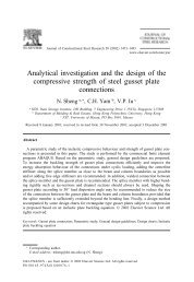
Fig. 15. Buckling of gusset <strong>plate</strong> (BGC).<br />
Brace<br />
section<br />
plotted in Fig. 17 is the total axial displacement measured at<br />
the location indicated in Fig. 13. Specimen GP2B5 was designed<br />
to have the brace yield in tension before the gusset<br />
<strong>plate</strong> <strong>and</strong> the gusset <strong>plate</strong> buckle in compression before<br />
buckling of the brace member. A comparison of Fig. 17a<br />
<strong>and</strong> 17b indicates that there is little difference in behaviour<br />
between load sequence LS1 <strong>and</strong> load sequence LS2. The<br />
gusset <strong>plate</strong> – brace member assembly behaviour <strong>under</strong> load<br />
sequence LS3 is similar to that observed <strong>under</strong> load sequence<br />
LS1 except for the fact that the initial stiffness of the<br />
assembly in tension tends to be smaller for load sequence<br />
LS3. The hysteresis curves for load sequence LS3 indicate<br />
that the capacity of the assembly deteriorates slightly with<br />
Failure mode<br />
Brace<br />
slenderness, kL/r Tension Compression<br />
B1 GP1 W200 × 21 50 YBT BGC<br />
B2 GP1 W200 × 21 100 YBT BBC<br />
B3 GP1 W200 × 27 50 YGT BGC<br />
B4 GP1 W200 × 27 100 YGT BBC<br />
B5 GP2 W200 × 27 50 YBT BBC<br />
B6 GP2 W200 × 27 100 YBT BBC<br />
B7 GP2 W200 × 42 50 YGT BGC<br />
B8 GP2 W200 × 42 100 YGT BBC<br />
B9 GP3 W200 × 31 50 YBT BBC<br />
B10 GP3 W200 × 31 100 YBT BBC<br />
B11 GP3 W200 × 59 50 YGT BGC<br />
B12 GP3 W200 × 59 100 YGT BBC<br />
Note: YGT, yielding of gusset in tension; YBT, yielding of brace in tension; BGC, buckling of gusset in compression;<br />
BBC, buckling of brace in compression.<br />
increasing number of cycles at each <strong>loading</strong> block. The differences<br />
between load sequence LS3 <strong>and</strong> load sequence LS1<br />
are believed to be very small. For this reason, the less time<br />
consuming load sequence LS1 was adopted for the remainder<br />
of the study.<br />
Effect of load limiting mechanism<br />
The load limiting mechanism in the tension cycle was either<br />
yielding of the brace member (YBT) or yielding of the<br />
gusset <strong>plate</strong> (YGT). In the compression cycle, the load limiting<br />
mechanism was either buckling of the brace member<br />
(BBC) or buckling of the gusset <strong>plate</strong> (BGC). Figure 18<br />
shows the difference in behaviour of the gusset <strong>plate</strong> – brace<br />
© 2005 NRC Canada