Gusset plate connections under monotonic and cyclic loading
Gusset plate connections under monotonic and cyclic loading
Gusset plate connections under monotonic and cyclic loading

You also want an ePaper? Increase the reach of your titles
YUMPU automatically turns print PDFs into web optimized ePapers that Google loves.
Walbridge et al. 989<br />
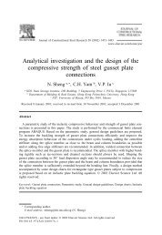
Fig. 13. Finite element model of the gusset <strong>plate</strong> – brace member subassembly.<br />
iour of the bolt slip model for an entire cycle. Some iteration<br />
was necessary in the selection of appropriate values for the<br />
bolt slip load <strong>and</strong> the assumed amount of slip. Due to the tediousness<br />
of the spring superposition procedure (which required<br />
stopping the analysis <strong>and</strong> modifying the model after<br />
each half cycle), only a few load cycles were modelled of<br />
the tests on specimens A1 <strong>and</strong> A3.<br />
Results<br />
Figure 11 shows axial load versus displacement plots for<br />
specimens A1 to A4 from Rabinovitch <strong>and</strong> Cheng (1993),<br />
along with the hysteresis plots predicted using the corresponding<br />
finite element models. Comparing the hysteresis<br />
plots for specimen A2 <strong>and</strong> A4, for which several load cycles<br />
were applied in the analysis, it can be seen that the finite element<br />
model predicts the buckling load <strong>and</strong> subsequent decay<br />
of the post-buckling load resistance <strong>under</strong> <strong>cyclic</strong> <strong>loading</strong><br />
quite well. The load resistance of the gusset <strong>plate</strong> in tension<br />
is also matched closely by the numerical model.<br />
A comparison of specimens A3 <strong>and</strong> A4, which had edge<br />
stiffeners, with A1 <strong>and</strong> A2 (with no edge stiffener) indicates<br />
that the effect of gusset <strong>plate</strong> edge stiffeners appears to be a<br />
reduction in the rate of decay of the post-buckling load. This<br />
corresponds well with the test results. Looking at the hysteresis<br />
plots for specimens A1 <strong>and</strong> A3, it can be seen that using<br />
the bolt slip model shown in Figs. 9 <strong>and</strong> 10, the finite element<br />
model is also able to predict the behaviour observed in<br />
these tests reasonably well considering the highly r<strong>and</strong>om<br />
nature of the bolt-slip phenomenon <strong>and</strong> the relatively simplistic<br />
nature of the modelling approach employed.<br />
A comparison of cumulative energy dissipation for specimens<br />
A2 <strong>and</strong> A4 is presented in Fig. 12. The energy dissipated<br />
was determined by calculating the area enclosed by<br />
the hysteresis loop for each cycle. The amount of dissipated<br />
energy predicted by the finite element model is slightly<br />
higher than the test values for both specimens. This is likely<br />
because the elasto-plastic material model was used in the <strong>cyclic</strong><br />
<strong>loading</strong> study. Although a study of the effect of strain<br />
hardening on buckling load showed only a small difference<br />
between material models, the effect of this parameter on the<br />
stiffness of the model once yielding had started was found to<br />
be significant. For specimen A2 especially, it was found that<br />
larger displacements had to be imposed on the compression<br />
side to cause buckling to occur as observed during the test.<br />
This meant that more energy was dissipated in this portion<br />
of each cycle. The cumulative energy dissipation curves for<br />
specimen A2 indicate that most of the difference between<br />
the two curves occurs in cycles 3, 4, <strong>and</strong> 5. In these cycles,<br />
higher displacements had to be imposed on the compression<br />
side to cause the gusset <strong>plate</strong> model to buckle during the<br />
same cycle as the test specimen. In subsequent cycles, the<br />
energy dissipated (per cycle) matches quite well.<br />
Parametric study<br />
For the parametric study presented in this section, the gusset<br />
<strong>plate</strong> model validated in the previous sections was modified<br />
to include a brace member. The model of the gusset<br />
<strong>plate</strong> <strong>and</strong> brace member is presented in Fig. 13. The objective<br />
of the parametric study was to exp<strong>and</strong> the experimental<br />
investigation performed by Yam <strong>and</strong> Cheng (1993) <strong>and</strong><br />
Rabinovitch <strong>and</strong> Cheng (1993) to include the effect of gusset<br />
<strong>plate</strong> – brace member interaction <strong>and</strong> load sequence.<br />
Using the modified model, three different load sequences<br />
were investigated. The first, designated LS1, consisted of a<br />
series of cycles of increasing displacement amplitude, starting<br />
with a tension cycle. The increase in the displacement<br />
amplitude with each cycle was taken as the yield displacement,<br />
δy, obtained from a <strong>monotonic</strong> load analysis of the<br />
gusset <strong>plate</strong> (based on the recommendations of the Applied<br />
© 2005 NRC Canada