Gusset plate connections under monotonic and cyclic loading
Gusset plate connections under monotonic and cyclic loading
Gusset plate connections under monotonic and cyclic loading

Create successful ePaper yourself
Turn your PDF publications into a flip-book with our unique Google optimized e-Paper software.
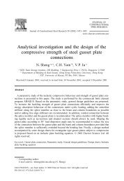
Walbridge et al. 987<br />
Fig. 9. Springs used to model bolt slip: (a) spring 1, (b) spring 2, <strong>and</strong> (c) spring 3..<br />
Fig. 10. Spring activation sequence for bolt slip model: (a) step1,(b) step2,(c) step3,<strong>and</strong>(d) step 4. Dashed lines represent springs<br />
that are “active” <strong>and</strong> solid lines represent the “effective” spring.<br />
Results<br />
On one h<strong>and</strong>, it was found that initial imperfection magnitude<br />
has a significant effect on the buckling capacity of the<br />
gusset <strong>plate</strong>; in general, the larger the initial imperfection,<br />
the lower the buckling capacity. On the other h<strong>and</strong>, it was<br />
found that the shape of the initial imperfection was much<br />
less critical. The quarter sine wave shape was used in subsequent<br />
analyses.<br />
The effect of initial imperfection magnitude was studied<br />
using a model of specimen GP3 from Yam <strong>and</strong> Cheng<br />
(1993). Figure 7 shows axial load versus displacement<br />
curves for models of the gusset <strong>plate</strong> connection with three<br />
different initial imperfection magnitudes. The figure<br />
indicates that an initial imperfection magnitude of 0.5 mm<br />
overestimates the capacity of the assembly, whereas a<br />
5.0 mm imperfection results in an <strong>under</strong>estimation of the test<br />
result.<br />
Based on the results of the analysis described above, new<br />
models of specimens GP1, GP2, <strong>and</strong> GP3 from Yam <strong>and</strong><br />
Cheng (1993) were constructed. A quarter sine wave initial<br />
imperfection with a magnitude of 2.0 mm was used, <strong>and</strong><br />
flexible beam <strong>and</strong> column members along the gusset <strong>plate</strong><br />
boundaries were included in the model. Table 3 shows a<br />
summary of the predicted <strong>and</strong> actual capacity in compres-<br />
© 2005 NRC Canada