PTO INSTALLATION and OWNER'S MANUAL - Muncie Power ...
PTO INSTALLATION and OWNER'S MANUAL - Muncie Power ...
PTO INSTALLATION and OWNER'S MANUAL - Muncie Power ...

Create successful ePaper yourself
Turn your PDF publications into a flip-book with our unique Google optimized e-Paper software.
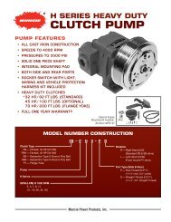
<strong>PTO</strong><br />
<strong>INSTALLATION</strong> <strong>and</strong><br />
OWNER’S <strong>MANUAL</strong><br />
FOR ALL 6-bOLT ANd 8-bOLT MOUNT<br />
SERIES OF MUNcIE <strong>PTO</strong>S<br />
KEEP IN VEHICLE<br />
READ OPERATING INSTRUCTIONS<br />
INSIDE BEFORE OPERATING <strong>PTO</strong><br />
<strong>Muncie</strong> <strong>Power</strong> Products, Inc. Member of the Interpump Hydraulics Group<br />
General Offices <strong>and</strong> Distribution Center • P.O. Box 548 • <strong>Muncie</strong>, IN 47308-0548 • (765) 284-7721<br />
FAX (765) 284-6991 • E-mail info@munciepower.com • Web site http://www.munciepower.com<br />
Drive Products, Exclusive Agents for Canada, ISO Certified by an Accredited Registrar<br />
IN84-03 (Rev. 9-08) Printed in the U.S.A.
WARNING<br />
READ <strong>MANUAL</strong> COMPLETELY INCLUDING THESE WARNINGS AND<br />
OPERATOR’S INSTRUCTIONS IN SECTION 3<br />
READ AND UNDERSTAND ENTIRE <strong>MANUAL</strong> BEFORE <strong>INSTALLATION</strong> OR<br />
OPERATION OF <strong>PTO</strong> AND DRIVEN EQUIPMENT<br />
ALWAYS DISENGAGE THE <strong>PTO</strong> WHEN THE DRIVEN EQUIPMENT IS NOT IN<br />
OPERATION.<br />
DO NOT ATTEMPT TO INSTALL OR SERVICE ANY POWER TAKE-OFF WITH THE<br />
TRUCK ENGINE RUNNING. PUT THE IGNITION KEYS IN YOUR POCKET BEFORE<br />
GETTING UNDER THE TRUCK.<br />
DO NOT ALLOW TRUCK ENGINE TO BE STARTED WHILE WORKERS ARE UNDER<br />
THE TRUCK.<br />
IMMOBILIZE TRUCK WHEELS WITH SUITABLE CHOCKS BEFORE WORKING<br />
UNDER TRUCK.<br />
BE SURE TO BLOCK ANY RAISED BODY OR MECHANISM BEFORE WORKING ON<br />
OR UNDER THE EQUIPMENT.<br />
INSTALLED POWER TAKE-OFFS MUST NEVER BE SHIFTED IN OR OUT OF GEAR<br />
BY ANY MEANS EXCEPT BY THE CONTROLS IN THE CAB OF THE TRUCK.<br />
STAY CLEAR OF SPINNING DRIVESHAFTS TO AVOID BECOMING ENTANGLED<br />
AND INJURED.<br />
IT SHALL BE THE RESPONSIBILITY OF THE INSTALLER OF A MUNCIE POWER<br />
TAKE-OFF TO DECIDE WHETHER TO INSTALL GUARDS IN THE <strong>PTO</strong> AND/OR<br />
DRIVELINE AREA BECAUSE OF POTENTIAL EXPOSURE TO DANGER.<br />
THIS IS BECAUSE MOST MUNCIE <strong>PTO</strong>S ARE INSTALLED BY EQUIPMENT<br />
DISTRIBUTORS OR MANUFACTURERS AND THEREFORE, THE RESPONSIBILITY<br />
OF THE <strong>INSTALLATION</strong> IS BEYOND THE CONTROL OF MUNCIE POWER PRODUCTS.<br />
OBTAIN PROPER TRAINING BEFORE OPERATING THIS MACHINERY<br />
DO NOT INSTALL OR OPERATE EQUIPMENT WHICH HAS NOT BEEN PROPERLY<br />
SPECIFIED FOR YOUR EQUIPMENT.<br />
ALLOW THE VEHICLE, <strong>PTO</strong> AND DRIVEN EQUIPMENT TO WARM UP WHEN<br />
OPERATING IN WEATHER WHERE TEMPERATURES ARE NEAR OR BELOW<br />
FREEZING 32 ºF (0 ºC).<br />
INSTALL SEPARATE CONTROLS FOR <strong>PTO</strong> AND DRIVEN EQUIPMENT<br />
ALWAYS INSTALL THE SAFETY LABELS PROVIDED AND PLACE THE OWNER’S<br />
<strong>MANUAL</strong> IN THE VEHICLE GLOVE COMPARTMENT.<br />
The <strong>PTO</strong> is supplied with a packet containing warning labels. If you did not<br />
receive any, or if you need extra, you may order them, no charge, by phone,<br />
email, or mail. They are available through your nearest <strong>Muncie</strong> distributor<br />
or at the number <strong>and</strong> address below:<br />
1-800-FOR-<strong>PTO</strong>S (367-7867)<br />
<strong>Muncie</strong> <strong>Power</strong> Products, Inc.<br />
P.O. Box 548<br />
<strong>Muncie</strong>, IN 47308-0548<br />
info@munciepower.com<br />
This symbol warns of personal injury.<br />
© <strong>Muncie</strong> <strong>Power</strong> Products, Inc. 2008
Table Of COnTenTs<br />
Section 1 <strong>PTO</strong> Installation<br />
<strong>PTO</strong> Installation Instructions ............................................................ 1.1<br />
Adapter Plates & Assemblies ........................................................... 1.10<br />
Adapter Gear Installation ................................................................. 1.11<br />
Filler Blocks 1.11<br />
Section 2 Activation Kit Installation<br />
Activation Kit Installation Instructions .............................................. 2.1<br />
Lever Shift Control ........................................................................... 2.1<br />
Cable Shift Instructions .................................................................... 2.2<br />
Indicator Light Switch Continuity Check ......................................... 2.7<br />
<strong>PTO</strong> Equipped with Magnetic Pick-Up Sensor ............................... 2.7<br />
TG Series Lectra Shift System ......................................................... 2.8<br />
TG Series Wiring Diagram for E-Hydra-Shift ................................... 2.9<br />
TG Series St<strong>and</strong>ard Air Shift System ............................................... 2.10<br />
TG Series Electric/Air Shift System ................................................. 2.10<br />
82 Series Double Acting Air Shift System ....................................... 2.11<br />
RG, RL Series St<strong>and</strong>ard Air Shift System ........................................ 2.11<br />
Automatic Transmission Diagrams ................................................... 2.12<br />
Clutch Shift <strong>and</strong> SH Series Electric/Air Shift System ...................... 2.18<br />
Clutch Shift <strong>and</strong> SH Series St<strong>and</strong>ard Air Shift System ................... 2.20<br />
Clutch Shift Electric/Hydraulic Shift System .................................... 2.21<br />
Clutch Shift Instructions & Tests ...................................................... 2.22<br />
Section 3 Owner’s Manual<br />
<strong>PTO</strong> OWNER’S <strong>MANUAL</strong><br />
FOR ALL 6-BOLT AND 8-BOLT<br />
MOUNT MUNCIE <strong>PTO</strong>S<br />
<strong>Power</strong> Take-Off Warranty ................................................................. 3.1<br />
<strong>PTO</strong> Shifting Procedure & Precautions ............................................ 3.2<br />
Clutch Shift Operating Notes ........................................................... 3.4<br />
<strong>PTO</strong> Maintenance ............................................................................ 3.4<br />
Indicator Light Check ....................................................................... 3.5<br />
<strong>PTO</strong> Torque & Horsepower Ratings ................................................. 3.6<br />
<strong>PTO</strong> Troubleshooting Guide ............................................................. 3.7
SectIoN 1<br />
Pto INStAllAtIoN<br />
Pto INStAllAtIoN INStRUctIoNS<br />
Always wear safety glasses. Read entire manual before starting installation.<br />
1.1<br />
1. There is a packet with the <strong>PTO</strong> which contains 4 WARNING LABELS.<br />
Before adhering the labels, make sure the surfaces are free of dirt <strong>and</strong><br />
grease. Place the labels supplied as follows:<br />
There are two (2) labels which measure approximately 4" x 8" which are to<br />
be placed on the outside of the vehicle frame rail, making them easy to be<br />
seen by anyone who might go under the truck or near the <strong>PTO</strong>. One label<br />
is to be placed on each side of the vehicle.<br />
Should the body installed on the chassis cover the frame rail, place the<br />
label on the body in a position easily visible by anyone who might go under<br />
the vehicle or near the <strong>PTO</strong>. Do not paint over labels.<br />
NEVER GET<br />
UNDER THIS<br />
TRUCK IF<br />
THE ENGINE<br />
IS RUNNING!<br />
Part No. 36M35644 (Rev. 9-06)<br />
© <strong>Muncie</strong> <strong>Power</strong> Products, Inc. 2006<br />
You may be<br />
hurt or killed.<br />
¡NUNCA SE<br />
META DEBAJO<br />
DEL CAMIÓN<br />
CUANDA EL<br />
MOTOR ESTÉ<br />
EN MARCHA!<br />
Figure 1.1<br />
There are two (2) 4" X 8" labels supplied <strong>and</strong> one is to be placed on each<br />
side of the vehicle.<br />
LOCATE ON FRAME RAIL.
2. The 2" x 3" <strong>PTO</strong> Equipped Caution Label is to be placed within the cab of<br />
the vehicle <strong>and</strong> in easy view of the vehicle operator. It should be located<br />
near the <strong>PTO</strong> control, when the control is installed in the vehicle dash<br />
(See Figure 1.2). This label directs the operator to read the <strong>PTO</strong> operating<br />
instructions on the “Visor Label”. The Visor Label 4" x 6 1/2" is to be<br />
placed on the visor on the operator’s side of the vehicle (See Figure 1.2).<br />
Do not mount this label on the same side of the visor as the air bag warning<br />
label if so equipped. Vehicles with hydraulic dump pumps are supplied<br />
with a Warning label to be mounted in clear view of the operator while<br />
seated in the driver’s seat.<br />
THIS VEHICLE IS<br />
EQUIPPED WITH A<br />
POWER TAKE-OFF<br />
READ AND UNDERSTAND<br />
OPERATOR'S <strong>MANUAL</strong><br />
BEFORE USING<br />
THIS MACHINE.<br />
FAILURE TO<br />
FOLLOW OPERATING<br />
INSTRUCTIONS COULD<br />
RESULT IN DEATH OR<br />
SERIOUS INJURY.<br />
ESTE VEHICULO ESTA<br />
EQUIPADO CON UNA<br />
TOMA DE FUERZA<br />
IMPORTANTE. FAVOR DE LEER<br />
Y CONSULTAR EL <strong>MANUAL</strong> DE<br />
OPERACION ANTES DE OPERAR<br />
Y MANEJAR ESTA UNIDAD.<br />
EL NO SEGUIR LAS<br />
INSTRUCCIONES DE<br />
OPERACION PUEDA RESULTAR<br />
EN HERIDAS PERSONALES<br />
O EN LA MUERTE.<br />
© <strong>Muncie</strong> <strong>Power</strong> Products, Inc. 2006 Part No. 36M35652 (Rev. 9-06)<br />
UNDERSTAND THIS LABEL BEFORE USING POWER<br />
TAKE-OFF (<strong>PTO</strong>). Refer to Owner's Manual in glove<br />
box or on the internet at: www.munciepower.com<br />
NEVER GET UNDER THIS<br />
TRUCK IF THE ENGINE<br />
IS RUNNING!<br />
H<strong>and</strong>s, clothes, hair, etc. can<br />
get caught on spinning shafts<br />
<strong>and</strong> U-joints.<br />
HOW TO USE THE<br />
POWER TAKE-OFF (<strong>PTO</strong>)<br />
STATIONARY APPLICATIONS:<br />
CHOCK WHEELS BEFORE<br />
ENGAGING <strong>PTO</strong>.<br />
Manual Shift <strong>PTO</strong>s<br />
(including Air Shift)<br />
Manual Transmissions<br />
1. Push in clutch pedal.<br />
2. Shift transmission into<br />
neutral.<br />
3. Engage <strong>PTO</strong>.<br />
4. Let clutch pedal out.<br />
Part No. 36T38634<br />
© <strong>Muncie</strong> <strong>Power</strong> Products, Inc. 2006<br />
COLOQUE LA CALCOMANIA CERCA DE<br />
LOS CONTROLES DE LA TOMA DE FUERZA<br />
LOCATE VISIBLE AND NEAR <strong>PTO</strong> CONTROL<br />
Figure 1.2<br />
YOU MAY BE HURT OR KILLED.<br />
It is against Federal Law to try to<br />
fix <strong>PTO</strong> driven machinery if the<br />
engine is running. Always turn the<br />
engine off. Then, put the keys in<br />
your pocket. (OSHA 1910.147)<br />
Manual Shift <strong>PTO</strong>s<br />
(including Air Shift)<br />
Automatic Transmissions<br />
1. Let engine idle.<br />
2. Apply brakes, while seated<br />
in driver's seat.<br />
3. Place shift selector in any<br />
drive range.<br />
4. Engage <strong>PTO</strong>.<br />
5. Shift transmission to<br />
neutral or park.<br />
<strong>Power</strong> Shift <strong>PTO</strong>s<br />
Manual or Automatic Trans.<br />
1. Let engine idle.<br />
2. Engage <strong>PTO</strong> with switch.<br />
3. Resume operating speed.<br />
COMO USAR LA<br />
TOMA DE FUERZA<br />
APLICACIONES<br />
ESTACIONARIAS: BLOQUEAR<br />
LAS LLANTAS<br />
ANTES DE ACTIVAR LA<br />
TOMA DE FUERZA.<br />
Tomas de fuerza de<br />
activación manual<br />
(incluye activación neumática)<br />
Transmisiones estándaresl<br />
1. Pise el embrague<br />
2. Cambie la transmisión<br />
a neutral<br />
3. Activa la toma de fuerza<br />
4. Desembragar<br />
LEA Y COMPRENDE ESTA CALCOMANÍA ANTES DE<br />
USAR LA TOMA DE FUERZA. Véase el manual del<br />
usuario. Visite el sitio www.munciepower.com<br />
¡NUNCA SE META DEBAJO PUEDA LASTIMARSE O SER MUERTO.<br />
EL CAMIÓN CUANDO EL Está en contra de leyes federales intentar<br />
MOTOR ESTÉ EN MARCHA! arreglar el equipo manejado por la toma de<br />
Cuídese las manos, la ropa, fuerza cu<strong>and</strong>o el motor está en marcha. En<br />
el pelo, etc. cu<strong>and</strong>o la flecha todas circunstancias sin excepción, apague<br />
cardán está gir<strong>and</strong>o. el motor y ponga las llaves en su bolsillo.<br />
(OSHA 1910.147)<br />
Transmisiones automáticas<br />
1. Prende el motor. No aumenta<br />
velocidad o RPM<br />
2. Frene mientras está sentado en<br />
la silla del conductor<br />
3. Cambia la transmisión a marcha<br />
(cualquier velocidad)<br />
4. Activa la toma de fuerza<br />
5. Cambia la transmisión a neutral<br />
o aparcamiento<br />
Tomas de fuerza de activación<br />
con embrague<br />
Transmisiones estándares o automáticas<br />
1. Prende el motor. No aumenta<br />
velocidad o RPM<br />
2. Activa la toma de fuerza con el interruptor<br />
3. Aumenta las RPM a la velocidad de<br />
operación deseada<br />
LOCATE ON VISOR SO IT IS VISIBLE WHEN THE SUN VISOR IS RAISED<br />
1.2
3. Manual Transmissions: While driving the truck into the work bay note if<br />
a delay is required between depressing the clutch <strong>and</strong> shifting the main<br />
transmission gear selection. If the gear does not come to a complete stop<br />
within a few seconds, the clutch linkage on the truck<br />
must be adjusted before installing the <strong>PTO</strong>. Run transmission<br />
in neutral. Determine sound of transmission<br />
before the <strong>PTO</strong> is installed. A transmission noise may<br />
be more noticeable after <strong>PTO</strong> is installed.<br />
Stop engine.<br />
4. For manual shift transmissions, drain<br />
transmission fluid. For Allison automatic<br />
transmissions, do not drain transmission<br />
fluid, but be prepared for a small<br />
amount of oil to escape from opening.<br />
Remove cover plate. Place a shop towel<br />
in the opening to prevent dirt from getting<br />
in the transmission.<br />
Examine cover plate. If there is a magnet<br />
attached to the inside, reinstall this<br />
cover on the other opening.<br />
Clean mounting pad. Inspect bolt holes<br />
in aperture for thread sealant used on OEM bolts. Clean these internal<br />
threads with wire brush to clear the material. Remove shop towel.<br />
5. Check transmission for proper <strong>PTO</strong> driver gear <strong>and</strong> location. Do not place<br />
anything in or near <strong>PTO</strong> opening while the engine is running.<br />
Stop engine <strong>and</strong> remove keys before proceeding to<br />
next operation.<br />
Check <strong>PTO</strong> driver gear for condition. A nick or blemish<br />
may cause excessive noise when <strong>PTO</strong> is mounted.<br />
6. Rock transmission gears by h<strong>and</strong> to get “feel” for gear<br />
backlash manufactured into transmission gear set.<br />
7. Open the <strong>PTO</strong> carton <strong>and</strong> find the mounting kit (studs <strong>and</strong> cap screws)<br />
enclosed with your <strong>PTO</strong>. Visual inspection of the <strong>PTO</strong> will indicate which<br />
mounting holes in the <strong>PTO</strong> will not accept cap screws. Install the enclosed<br />
studs in the transmission housing holes that correspond to those <strong>PTO</strong><br />
holes which will not accept cap screws. Additional instructions may be<br />
found on the supplement sheet enclosed with <strong>PTO</strong>. Install adapter gear at<br />
this point if it is required. (Go to page 1.10 if adapter gear is used.) <strong>PTO</strong>s<br />
with mounting option “6F” have two dowel pins which need to be placed<br />
in the mounting pad before mounting <strong>PTO</strong>.<br />
8. Install the studs until the barrel of the stud is even with the transmission<br />
pad. This typically requires a torque limit of 30-35 lbs.-ft. (6 bolt pad) or 45-<br />
50 lbs.-ft. (8 bolt pad). If more torque is required to install the stud to the<br />
barrel or to the depth shown in the below table then remove the lock patch<br />
from the stud <strong>and</strong> the transmission mounting holes <strong>and</strong> use a liquid loctite in<br />
its place (#242).<br />
1.3
The studs should be engaged to the minimum depth as shown below:<br />
Stud Dia. No. Threads Approx. Depth<br />
3/8" 7 - 8 1/2"<br />
7/16" 8 - 9 5/8"<br />
10mm 9 - 10 1/2"<br />
9. Remove the shifter cover or the inspection cover plate from the <strong>PTO</strong> by<br />
removing the hex head cap screws on the cover plate. With <strong>PTO</strong>s which<br />
do NOT have an inspection cover plate, hold<br />
the output shaft <strong>and</strong> rock input gear to get<br />
the “feel” of backlash built into the <strong>PTO</strong>. This<br />
“feel” will be helpful when fitting <strong>PTO</strong> to transmission.<br />
(Step 12)<br />
10. Place mounting gasket/shim from your kit over<br />
the studs already installed on the transmission.<br />
A thin coating of approved transmission oil is<br />
recommended on gasket/shims to help seal<br />
<strong>and</strong> to hold them in place during installation.<br />
The <strong>PTO</strong>s for the Eaton Lightning Transmission are<br />
designed to be mounted without gasket/shims <strong>and</strong><br />
require the use of a gasket eliminator which is supplied<br />
with the <strong>PTO</strong>.<br />
Do not use a permanent sealant on gasket/shims<br />
because you may need to change them later. Use<br />
approved transmission oil only!<br />
11. Position the <strong>PTO</strong> on the studs <strong>and</strong> start the nuts provided onto the studs<br />
Do Not Tighten Yet. Check for gaps between the <strong>PTO</strong> <strong>and</strong> transmission<br />
<strong>and</strong> make sure gear teeth are properly meshed <strong>and</strong> then tighten the top <strong>and</strong><br />
bottom nuts or cap screws. On some transmission models the TG Series<br />
<strong>PTO</strong> may encounter interference with the idler shaft cap. Special clearance<br />
caps may be used <strong>and</strong> are listed in the application catalog where known<br />
interference exists.<br />
12. Check the backlash on the input gear (gear that meshes with transmission<br />
gear) by feeling through the inspection hole or shift cover opening previously<br />
uncovered in step 9. The amount of rotational movement of the <strong>PTO</strong> gear<br />
should be only .006" to .012". As a reference, the thin gasket/shim in your<br />
installation kit is .010" thick. The thin gasket/shim (.010" thick) will change<br />
the backlash approx. .006". The amount of movement of the input gear<br />
would only be about the same distance as this gasket/shim thickness. At<br />
least one gasket/shim must be used. Do not stack more than (4) gasket/<br />
shims together. On Allison transmissions (Series AT-500, MT-600, HT-700,<br />
1000, 2000, 2400 only) the single .030" gasket/shim (13M13541) should<br />
be required <strong>and</strong> is supplied with <strong>PTO</strong>. The CS6B/SH6B-A6907 series <strong>and</strong><br />
TG6B-A69** Series uses the 23M60270 spacer <strong>and</strong> requires gasket/shims<br />
<strong>and</strong> backlash checks as described below.<br />
Special Instructions for Allison 1000 & 2000 Series Transmission<br />
Installations.<br />
Noise can occasionally be emitted from the <strong>PTO</strong> when installed on the<br />
Allison 1000/2000 Series transmissions that may be objectionable to the<br />
operator. The following instructions assist in reducing this noise.<br />
1.4
Noise emitting when the unit is disengaged <strong>and</strong> the reduced or extinguished<br />
when unit is engaged is common for this installation <strong>and</strong> is not a signal of<br />
advanced failure. <strong>Muncie</strong> <strong>Power</strong> Products does not consider this noise to<br />
be a warrantable condition.<br />
TG SERIES<br />
1.5<br />
When installing the TG series note that the <strong>PTO</strong> is provided with several<br />
gaskets <strong>and</strong> a steel spacer 23M60270.<br />
Install the <strong>PTO</strong> using two .020” thick gaskets provided, using one on each<br />
side of the spacer.<br />
Check the backlash. Backlash measurement should be in the range .010<br />
to .024”.<br />
If the <strong>PTO</strong> is noisy in the off mode, but quiet when engaged, then remove<br />
<strong>PTO</strong> <strong>and</strong> re-install with all of the gaskets provided.<br />
CS6 SERIES<br />
CS6B-A68 03 thru 05 ratios: When installing the <strong>PTO</strong> use one of the two<br />
13M13541 gaskets.<br />
If <strong>PTO</strong> is noisy in the off mode <strong>and</strong> quiet when engaged then, remove <strong>PTO</strong><br />
<strong>and</strong> re-install using both 13M13541 gaskets provided.<br />
CS6B-A69 07 ratio: Install the <strong>PTO</strong> using two .020” thick gaskets provided,<br />
using one on each side of the 23M60270 spacer provided with <strong>PTO</strong>.<br />
Check the backlash. Backlash measurement should be in the range .010<br />
to .024”.<br />
If the <strong>PTO</strong> is noisy in the off mode, but quiet when engaged, then remove<br />
<strong>PTO</strong> <strong>and</strong> re-install with all of the gaskets provided.<br />
GM6B/ GA6B SERIES<br />
Install <strong>PTO</strong> using both 13M13541 gaskets provided. See IN03-01<br />
Notice: For some Warner W80 applications, a maximum of one thin<br />
gasket/shim (.010") is required. If backlash is too excessive, remove the<br />
gasket/shim <strong>and</strong> use Loctite Gasket Eliminator sealant <strong>Muncie</strong><br />
#13M51717. A .20 ounce tube has<br />
been supplied with the <strong>PTO</strong> for these<br />
applications.<br />
Use of a dial indicator can greatly<br />
improve the quality of the installation.<br />
Mount the indicator so that the plunger<br />
aligns with a tooth on the <strong>PTO</strong> input<br />
gear. Hold the transmission gear with<br />
screw driver or bar <strong>and</strong> rock the <strong>PTO</strong><br />
gear back <strong>and</strong> forth with your h<strong>and</strong>. The
total movement on the dial indicator should be between .006" - .012". Check<br />
the backlash at different points around drive gear to find the worst condition.NOTE:<br />
Never use silicone type sealant on <strong>PTO</strong>/transmission mounting<br />
surface as proper backlash cannot be attained.<br />
13. Torque all the mounting cap screws or nuts to 40-45 lb-ft (6-bolt pad) or<br />
50-55 lb-ft (8-bolt pad) unless noted in a separate stud kit instruction.<br />
Failure to properly tighten capscrews or nuts can lead to leaks. <strong>PTO</strong> <strong>and</strong>/<br />
or transmission damage can occur. Improper installation, tightening, or<br />
leaks are not the responsibility of <strong>Muncie</strong> <strong>Power</strong> Products, Inc.<br />
Recheck the backlash.<br />
The <strong>PTO</strong> gear should not move more than .012 or less than .006 when all<br />
mounting nuts or bolts have been torqued.<br />
14. Replace shifter cover or inspection cover plate <strong>and</strong> gasket on the <strong>PTO</strong>.<br />
Shifter cover gasket can be found in the instruction<br />
envelope. It is required to use a gasket<br />
under the shift cover. Torque cap screws to 14-18<br />
lb.-ft. Double check to make sure the shifter fork is<br />
in the groove on gear or shift collar before tightening<br />
cap screws. On the TG Series shifter cover, the<br />
installation <strong>and</strong> torqueing of the capscrew should<br />
be in an "X" pattern starting with the center capscrews<br />
<strong>and</strong> crossing the cover during installation.<br />
Torque the capscrews using the same pattern.<br />
15. Start the truck engine (with transmission <strong>and</strong> <strong>PTO</strong> in neutral) for a few<br />
seconds <strong>and</strong> listen for unnatural noises. Stay clear of rotating components.<br />
A whine noise indicates the <strong>PTO</strong> is mounted too tight. Stop<br />
engine <strong>and</strong> add a gasket/shim. A clatter noise indicates a loose mount.<br />
Stop engine <strong>and</strong> remove a gasket/shim. Add sealant (Loctite gasket<br />
eliminator 6<br />
4<br />
2<br />
1<br />
3<br />
5<br />
"X" PATTERN<br />
) if no gasket is used.<br />
• A <strong>PTO</strong> will not always make these noises.<br />
• Do Not adjust backlash by noise alone, always visually check back<br />
lash.<br />
• Sometimes filling the transmission with lube is the only way to<br />
reduce the noise.<br />
• A tight mounted <strong>PTO</strong> will cause under cutting of gears <strong>and</strong> result in<br />
pre mature <strong>PTO</strong> failure, including gear or housing breakage.<br />
• If OK, repeat test with <strong>PTO</strong> engaged.<br />
Caution: Keep <strong>PTO</strong>/transmission running time as short as possible until<br />
transmission is refilled with lube. Do not drive the truck without transmission<br />
lube.<br />
16. Refill transmission with manufacturer’s approved fluid <strong>and</strong> run engine<br />
for 5 to 10 minutes to check for<br />
leaks. Stay clear of rotating components.<br />
Stop Engine! Inspect the<br />
cap screws, nuts, <strong>and</strong> studs to<br />
make sure they are properly tightened.<br />
After completing installation,<br />
installers need to check for leaks<br />
<strong>and</strong> proper mounting torque of <strong>PTO</strong><br />
fasteners. Refer to Step 21.<br />
1.6
17. Install the appropriate shifter kit components, including the supplied <strong>PTO</strong><br />
shift indicator light. Refer to page 2.1 for lever shift, page 2.2 thru 2.7 for<br />
cable shift, page 2.8 for the Lectra Shift TG series <strong>PTO</strong>, pages 2.9 thru<br />
2.10 for Air Shift <strong>PTO</strong>s, <strong>and</strong> pages 2.11 thru 2.20 for Clutch Shift <strong>PTO</strong>s.<br />
On air system only, you will not receive any air through the pressure protection<br />
valve to the <strong>PTO</strong> system until your main tank pressure exceeds 65<br />
PSI.<br />
18. If your system utilizes a driveline between the <strong>PTO</strong> <strong>and</strong> another device <strong>and</strong><br />
if you have noise in your system that was not there before, the angularity or<br />
phasing of your driveline may be the cause. Check driveline angularity <strong>and</strong><br />
reduce total angularity per recommendation on chart <strong>and</strong> be sure the <strong>PTO</strong><br />
shaft is parallel within 1.5° to the pump shaft (or driven unit). Drivelines<br />
must be in phase, that is, the yoke ears on the <strong>PTO</strong> <strong>and</strong> pump shafts must<br />
be in alignment, as illustrated below.<strong>PTO</strong> with Direct Couple Hydraulic<br />
Pump Installation<br />
1.7<br />
Max. Max.<br />
Speed TJA<br />
(RPM) “A”<br />
*3500* 5°<br />
*3000* 5°<br />
2500 7°<br />
2000 8°<br />
1500 11°<br />
1000 12°<br />
For installations with angles in the top <strong>and</strong> side views use this formula to<br />
compute the true joint angle (TJA):<br />
TJA = A2 + B2 A<br />
TOP VIEW<br />
TRANSMISSION<br />
<strong>PTO</strong><br />
B<br />
PuMP<br />
* For speeds over 2500 RPM contact <strong>Muncie</strong> for Approval.<br />
PuMP
FOR cAbLE OR LEVER SHIFT <strong>INSTALLATION</strong>S ONLY.<br />
Before bolting the pump to the <strong>PTO</strong>, place<br />
non-seizing compound or grease on the<br />
<strong>PTO</strong> shaft <strong>and</strong> pump shaft.<br />
All <strong>Muncie</strong> direct mount <strong>PTO</strong>s are supplied<br />
with the appropriate grease. Reusing an<br />
existing pump will require inspection of the<br />
pump splines. Clean any old grease from<br />
pump prior to installation.<br />
When mounting hydraulic pumps weighing<br />
over 40 lbs.*, exceeding 12" in length, or for t<strong>and</strong>em or<br />
multiple section pumps, a rigid support bracket must be<br />
installed. It should be attached to the rear of the pump <strong>and</strong> to<br />
the transmission to support the pump <strong>and</strong> to inhibit<br />
movement in all directions.<br />
*Weight includes fittings, oil, <strong>and</strong> unsupported hose sections.<br />
This requirement does not take into account the system<br />
duty cycles, vehicle vibrations, application, terrain, <strong>and</strong><br />
other external influences. We recommend that direct<br />
mounted components of any size or weight be supported<br />
when these conditions are extreme or unknown.<br />
(Do not force spline<br />
couplings together)<br />
This recommendation is based upon our experiences to date. Bracket design<br />
illustrations <strong>and</strong> pump recommendations is to be used as a GUIDELINE ONLY.<br />
Bracket design shown is representative <strong>and</strong> is not to be duplicated for all<br />
applications. Any failure as a result of damage caused by unsupported weight<br />
attached to the <strong>PTO</strong> will affect any warranty considerations.<br />
The drawings below are examples of how the bracket may be constructed.<br />
A bracket attached to two or more transmission bolts <strong>and</strong> two pump bolts<br />
is required. The bracket design should assure that there is no stress or force<br />
exerted on the pump or <strong>PTO</strong> shaft.<br />
If the vertical supports<br />
are greater than 20<br />
degrees off of perpendicular<br />
with the<br />
transmission main<br />
shaft then a reinforced<br />
“Z” bracket must be<br />
used. Reinforce horizontal<br />
members to<br />
prohibit flexing at bend or weld. Attach the bracket at the pump bolt closest to<br />
the center of gravity of the pump.<br />
Most <strong>Muncie</strong> direct mount flanges offer multiple mounting bolt holes which allow<br />
the flange to be rotated to multiple locations on the <strong>PTO</strong> for improved port location<br />
or clearance. Be sure to torque the cap screw to 25 ft.lb., <strong>and</strong> it is advisable<br />
to use a thread locker to secure the cap screws (Loctite 241 or NyLoc or<br />
equivalent).<br />
1.8
19. Greaseable hydraulic output shaft option.<br />
<strong>PTO</strong>s with the “G” special feature option<br />
have a grease zerk fitting behind a cover<br />
on the closed end cap of the output shaft.<br />
Grease needs to be added after the pump<br />
has been installed using a grease gun.<br />
Use a high temperature, high pressure,<br />
EP type grease.<br />
20. FOR cAbLE OR LEVER SHIFT <strong>INSTALLATION</strong>S ONLY.<br />
1.9<br />
For CLUTCH SHIFT installations,<br />
skip to pages 2.12 - 2.21.<br />
Using the metal plate as a template,<br />
drill holes in dash near cable knob <strong>and</strong><br />
attach indicator light as shown at right.<br />
Battery connection should be an “ACC”<br />
tap on fuse panel.<br />
Install light in a position which is visible to<br />
the operator when operating the <strong>PTO</strong><br />
<strong>and</strong> the vehicle.<br />
The indicator light is to be connected so that when the <strong>PTO</strong> is engaged the<br />
light is “ON” <strong>and</strong> the light is “OFF” when the <strong>PTO</strong> is disengaged.<br />
83 SERIES<br />
Do not install any other electrical<br />
devices to <strong>Muncie</strong> indicator<br />
switches, or to pressure switches.<br />
See page 2.12 for wiring indicator<br />
switch to the Eaton Fuller CEEMAT<br />
transmissions.<br />
21. Complete installation by placing warning labels as indicated on borders<br />
of the decals. Placement examples are illustrated on pages 1.1 <strong>and</strong> 1.2.<br />
Turn to Section 3 of Owner's Manual.<br />
After complete installation, installers needs to check for leaks <strong>and</strong> proper<br />
mounting-torque of fasteners. Operate the equipment for an appropriate<br />
amount of time established for proper operation or per the equipment<br />
manufacturer's recommendation. After shutting down equipment <strong>and</strong><br />
engine, check for leaks. Allow unit to sit for 60 minutes, then check again<br />
for any leaks. Fix all found leaks per manufacturer's recommendation.<br />
<strong>Muncie</strong> <strong>Power</strong> Products, Inc. is not responsible for any damage resulting<br />
from installation, mounting torque or maintenance of the <strong>PTO</strong>.
22. Complete installation by placing warning labels as indicated on borders of<br />
the decals. Placement examples are illustrated on pages 1.1 <strong>and</strong> 1.2. Turn<br />
to Section 3 of Owner’s Manual.<br />
AdAPteR PlAteS & ASSemblIeS<br />
See <strong>Muncie</strong> Quick Reference Catalog for specifications.<br />
ADAPTER PLATES are used to convert an SAE 8-bolt aperture to an SAE 6bolt<br />
aperture.<br />
Adapter plates<br />
mount to the transmission<br />
pad with<br />
included gaskets<br />
<strong>and</strong> capscrews.<br />
The 1/4" plate<br />
Adapter Plate has a raised pad<br />
to provide proper<br />
thread engagement.<br />
This raised pad is to be mounted toward<br />
the transmission opening <strong>and</strong> the <strong>PTO</strong> is<br />
mounted to the flush side of the plate.<br />
ADAPTER GEAR ASSEMBLIES are normally used to reverse the rotation of the<br />
<strong>PTO</strong> output shaft. They are also commonly specified to clear mounting obstructions.<br />
St<strong>and</strong>ard adapters will move the <strong>PTO</strong> outward from the transmission<br />
approximately three inches. Adapters often reduce the application horsepower<br />
ratings <strong>and</strong> service life. Contact <strong>Muncie</strong> for specific information<br />
regarding your application.<br />
Solid Body – Single Gear<br />
Angular Cluster Gear<br />
Mount Towards Transmission<br />
Flanged Body – Single Gear Vertical Offset Gear<br />
1.10
AdAPteR GeAR INStAllAtIoN<br />
Before installing the adapter gear be sure to read all of the instructions in this<br />
booklet for installing a <strong>PTO</strong>. Follow all the safety instructions listed when<br />
installing the adapter as you would for installing the <strong>PTO</strong>. Make sure that the<br />
engine is turned off <strong>and</strong> wheels are immobilized before starting any installation.<br />
1. Follow steps 1 through 7 on pages 1.1 through 1.3 of this manual.<br />
2. Before attempting to mount adapter to transmission, bench mount the<br />
adapter to the <strong>PTO</strong> using studs or capscrews in at least the top <strong>and</strong> bottom<br />
stud holes.<br />
3. Using gaskets <strong>and</strong> spacers (if required) adjust the backlash between the<br />
adapter <strong>and</strong> the <strong>PTO</strong> so that it is between .006" to .012". Some adapters<br />
are supplied with gasket eliminator instead of gaskets. Apply a bead<br />
evenly around the surface of the mounting pad.<br />
4. After spacing between <strong>PTO</strong> <strong>and</strong> adapter is adjusted remove the adapter<br />
from the <strong>PTO</strong> <strong>and</strong> carefully save the Gasket Pack you have just created.<br />
Mount the adapter to the transmission using at least the top <strong>and</strong> bottom<br />
stud holes. Adjust the backlash of the adapter to the transmission so that<br />
it is .006" to .012" inches. Refer to steps 8 through 12 on pages 1.3 <strong>and</strong><br />
1.4 for additional instructions on backlash.<br />
5. Using the Gasket Packs created from earlier steps, mount the <strong>PTO</strong> to the<br />
adapter using all six studs stud holes <strong>and</strong> return to the instructions on<br />
page 1.3, step 8 <strong>and</strong> continue the installation until completed.<br />
FIlleR blockS/SPAceRS<br />
FILLER BLOCKS are often required in transmission<br />
applications where it is necessary to use a spacer to<br />
adapt the <strong>PTO</strong> to a particular transmission. Two filler<br />
blocks may be used in combination with one or more<br />
gaskets between the filler block surfaces. A minimum of<br />
one (1) gasket is required between each surface. Refer to<br />
notice supplied with the filler block for more information.<br />
1.11
SectIoN 2<br />
ActIvAtIoN kIt INStAllAtIoN<br />
all INSTALLERS musT REAd THE FOLLOWINg<br />
ActIvAtIoN kIt INStAllAtIoN INStRUctIoNS<br />
ImpOrTanT: Disconnect vehicle battery <strong>and</strong> bleed air tanks with engine<br />
stopped prior to installing electrical or air activation kits.<br />
A. Vehicle manufacturers may have specific locations for the accessing of electrical<br />
power, activating hydraulics, <strong>and</strong> air. The body builder manual or company representative<br />
for the vehicle chassis should be contacted prior to installing electrical<br />
or pneumatic systems.<br />
B. Route wires, hydraulic activation lines, <strong>and</strong> air lines away from rotating <strong>and</strong> high<br />
temperature components. Use appropriate looms <strong>and</strong> bulkhead pass-thrus<br />
wherever possible to avoid rubbing through insulation or tubing <strong>and</strong> causing an<br />
electrical short or air leak.<br />
C. Follow all Federal Motor Vehicle Safety St<strong>and</strong>ards (FMVSS) for your<br />
vehicle.<br />
D. Where electrical grounds are indicated, be sure that they are good<br />
grounds, with straight paths to the vehicle battery ground. (Many vehicle<br />
cabs are insulated from the vehicle frame <strong>and</strong> a weak ground is a very common<br />
cause for malfunctions). Check with the vehicle manufacturers for the<br />
proper ground location or connect directly to battery.<br />
E. When installing hydraulic components, be certain to follow common installation<br />
<strong>and</strong> testing procedures. If you are not familiar with acceptable installation procedures<br />
request instructions <strong>and</strong> guidance from the hydraulic equipment supplier.<br />
F. Note that when installing the <strong>PTO</strong> air systems the installation of a pressure<br />
protection valve is required at the air tank. This valve is not a pressure regulator,<br />
it is a pressure check valve which does not allow air to the <strong>PTO</strong> system<br />
until the system air pressure exceeds approximately 65 PSI.<br />
G. Cold weather start conditions require that the transmission be started<br />
<strong>and</strong> warmed prior to engaging <strong>and</strong> using equipment. Hydraulic pumps<br />
should be run at idle <strong>and</strong> under no load conditions to allow oil to warm before<br />
activating hydraulic system.<br />
leveR SHIFt coNtRol<br />
Install indicator light as described on page 1.8, step 19.<br />
<strong>Muncie</strong> <strong>PTO</strong>s with lever shift options (available on *RG, RL, 82, 83 Series only)<br />
require the customer to provide the linkage <strong>and</strong> hook-up to the <strong>PTO</strong>. The <strong>PTO</strong> is<br />
provided with an eye bolt for this purpose.<br />
The <strong>PTO</strong> is designed with detent ball <strong>and</strong> spring to locate the engage <strong>and</strong> disengage<br />
positions, but it is not designed to lock into these positions. A neutral<br />
detent to prevent unintentional or accidental engagement must be installed<br />
on the external shift linkage. This detent must be included by the installer of<br />
the linkage.<br />
Tighten after shifting<br />
adjustments have<br />
been made.<br />
2.1
cAble SHIFt INStRUctIoNS<br />
Tg SERIES <strong>PTO</strong><br />
Sg SERIES <strong>PTO</strong><br />
Rg SERIES <strong>PTO</strong><br />
2.2<br />
Figure 2.1<br />
Figure 2.2<br />
Figure 2.3<br />
WARNING: All cable shift controlled <strong>PTO</strong>s are designed to be shifted only by wire<br />
cable. The unauthorized attachment of lever control linkage to a cable control<br />
mechanism may cause damage to shifting components <strong>and</strong>, subsequently, the<br />
transmission. The unauthorized attachment of the lever control linkage to a cable<br />
control mechanism may cause the <strong>PTO</strong> to engage unintentionally due to linkage<br />
bounce or flail.
cAbLE SHIFT <strong>INSTALLATION</strong> INSTRUcTIONS<br />
Be sure vehicle in not running when installing or adjusting cable control. After<br />
removing the cable from shipping liner (being very careful to hold cable so that it<br />
cannot uncoil <strong>and</strong> cause injury) straighten cable at crimp that has resulted from<br />
being coiled. Make sure cable has free travel before installing.<br />
Make sure cable has free travel.<br />
Remove Cable from shipping<br />
liner, so that it cannot uncoil<br />
<strong>and</strong> cause injury.<br />
The coiling of the cable<br />
causes a kink at the crimp.<br />
Straighten this before installing<br />
cable.<br />
1. Find a suitable location for the control cable <strong>and</strong> the indicator light. The<br />
cable control should be installed so that the operator has easy access<br />
to push in <strong>and</strong> pull out the control without obstruction or interference by<br />
other controls or components in the cab.<br />
2. Drill a 1/2" hole in dash or control bracket (not provided).<br />
3. Install the control head through the hole <strong>and</strong> attach with the lock washer<br />
<strong>and</strong> nuts provided.<br />
4. Knob can be screwed into place, using the jam nut to secure.<br />
Figure 2.4<br />
2.3
5. Route the length of cable through the floorboard or firewall <strong>and</strong> to the <strong>PTO</strong>.<br />
The cable needs to be routed clear of manifold, exhaust systems, <strong>and</strong> rotating<br />
<strong>and</strong> moving components. When routing the control cable avoid kinking<br />
the cable <strong>and</strong> do not bend to radius of less than 6"<br />
6. The lever on the <strong>PTO</strong> shifter assembly is designed so that it can be moved<br />
to allow the cable approach to be from the front or the back of the <strong>PTO</strong>. This<br />
should be determined by the routing method causing the least amount of<br />
bends <strong>and</strong> the shortest cable length.<br />
7. The lever, also must be positioned so that when you pull on the control knob<br />
that the <strong>PTO</strong> engages. (The RG Series should have a detent position for<br />
neutral, instead of pushing all the way in for neutral.)<br />
2.4
8. To adjust the lever, mark the position of the lever where it’s engaged when<br />
the cable would pull the lever. Remove the shift cover from the <strong>PTO</strong>.<br />
Remove the locking capscrew from the control lever. Lift the lever from the<br />
serrated post. Line up the lever with your mark. Line up the serrated hole <strong>and</strong><br />
post making sure that the poppet <strong>and</strong> the shift plate are in their respective<br />
positions. Replace the locking capscrew <strong>and</strong> torque to 18 ft.lb. Reinstall shift<br />
cover assembly. Double check the installation by referring back to step 7 on<br />
the previous page 2.4.<br />
Move lever to its fully<br />
disengaged position <strong>and</strong><br />
the cable knob to its<br />
fully disengaged position.<br />
2.5
2.6<br />
9. Referring to Figs. 2.1, 2.2, 2.3 on page 2.2, install the appropriate brackets,<br />
clamps, <strong>and</strong> hardware.<br />
STANdARd <strong>PTO</strong> cAbLE<br />
If the cable is too long, remove the inner wire <strong>and</strong> cut<br />
casing (only) to length with a hacksaw or large side<br />
cutters.<br />
If longer cables are required - they are available<br />
from your nearest <strong>Muncie</strong> Independent Master<br />
Warehouse.<br />
dELUxE (PT-65) <strong>PTO</strong> cAbLE<br />
Abrasive power cutting equipment<br />
is recommended for shortening<br />
this type of control cable. Do not<br />
use a bolt cutter or similar tool.<br />
Described here is a h<strong>and</strong> method<br />
for cutting cables where abrasive<br />
power cutting equipment is not<br />
available.<br />
Make a holding tool by using a<br />
hardwood block of any conve-<br />
Typical Block Dimensions Shown<br />
nient length as shown in the diagram.<br />
The hole should be of a size<br />
just large enough for the conduit<br />
to easily slip through.<br />
The hacksaw should have a fine tooth blade (no less than 32 teeth per<br />
inch). Remove the inner wire before cutting conduit by pulling the control<br />
knob end from the control head. Remove the installed cable end by<br />
unscrewing it from the cable conduit <strong>and</strong> saving it for reinstallation.<br />
10. It is recommended that the control cable casing be securely anchored,<br />
with cable clamps, approximately every 30", to the frame <strong>and</strong>/or cab to<br />
prevent movement during shifting. Cable mounting clamps can be purchased<br />
from your nearest <strong>Muncie</strong> Independent Master Warehouse. (part<br />
no. MT306-4)<br />
11. Install the indicator light <strong>and</strong> warning labels by referring to steps 19 & 20<br />
on page 1.9 of this instruction booklet. The indicator light is to be “ON”<br />
when the <strong>PTO</strong> is engaged <strong>and</strong> “OFF” when the <strong>PTO</strong> is disengaged.<br />
Do not install other electrical devices to the <strong>Muncie</strong> indicator light<br />
switch.<br />
Install cable so that you pull to engage <strong>and</strong><br />
fully pushed in to disengage.<br />
The <strong>PTO</strong> indicator light must be installed so that it is visible to the operator<br />
of the vehicle while seated in the driver’s seat. Additional indicator<br />
lights may need to be purchased to comply with this requirement.
INdIcAtoR lIGHt SWItcH<br />
coNtINUItY cHeck<br />
Performing a continuity check on the indicator switch will verify that the indicator<br />
switch is functioning <strong>and</strong> that the <strong>PTO</strong> is properly assembled.<br />
1. Using a multimeter, connect one lead to the spade terminal on the indicator<br />
switch mounted to the <strong>PTO</strong>.<br />
2. Connect the other lead to a bare metal portion of the <strong>PTO</strong> or shifter<br />
(Figure 2.5).<br />
3. If the <strong>PTO</strong> is mounted on a vehicle, be sure that the engine is stopped, <strong>and</strong><br />
the vehicle is safely immobilized to prevent any movement.<br />
4. Engage the <strong>PTO</strong>. The meter will show continuity (Figure 2.6).<br />
5. Shift <strong>PTO</strong> to the disengage position. The meter should return to normal<br />
(Figure 2.5).<br />
This continuity check may be performed on any <strong>Muncie</strong> <strong>PTO</strong>. Only the air shifted<br />
models will require an air source to engage the <strong>PTO</strong>.<br />
<strong>PTO</strong> EQUIPPEd WITH MAgNETIc PIcK-UP SENSOR<br />
1. Mount the shift cover to the <strong>PTO</strong> (as required).<br />
2. Align the internal gear tooth so that tip is centered in the pick-up opening.<br />
3. Install the jam nut with the seal in the nut facing the <strong>PTO</strong> <strong>and</strong> back it<br />
down the pick up close to the wire end. Place washer then the o’ring on<br />
the pick up so that the<br />
o’ring will be against the<br />
<strong>PTO</strong> cover. Screw in<br />
the pick-up until the tip<br />
gently touches the top of<br />
the gear tooth.<br />
4. Turn the pick-up backwards<br />
2 turns. Rotate<br />
gear to make sure it<br />
clears.<br />
5. Hold pick-up <strong>and</strong> tighten<br />
jam nut to hold in place.<br />
6. Re-Check gear for rotation.<br />
Figure 2.5 Figure 2.6<br />
16TK3833 OR 31TK3873 SPEEd SENSOR KIT<br />
Pulse Generator<br />
31T35108<br />
<strong>PTO</strong><br />
GEAR<br />
Seal Jam Nut<br />
21T35109<br />
(Jam Nut seal<br />
mount towards flat<br />
washer or <strong>PTO</strong>)<br />
Flat Washer<br />
21T36099<br />
O-Ring<br />
12T35774<br />
2.7
Tg SERIES LEcTRA SHIFT SYSTEM<br />
IMPORTANT:<br />
1. The dash bracket is to be mounted in cab<br />
within easy reach of operator.<br />
2. The control relay should be mounted on<br />
firewall in engine compartment.<br />
3. 10 ga. wires from battery to relay <strong>and</strong> from<br />
relay to solenoid should not be lengthened.<br />
4. <strong>PTO</strong> engagement is made by pushing rocker<br />
switch fully to the engage position <strong>and</strong> releasing<br />
switch immediately upon engagement.<br />
5. Excessive repeated shifting of <strong>PTO</strong> can<br />
overheat solenoid <strong>and</strong> prevent engagement until allowed to cool down.<br />
6. Drill .625 dia. hole in firewall near where control relay is mounted. Install black plastic grommet (P/N 37T35674) in hole<br />
<strong>and</strong> run the four wire connector through the grommet <strong>and</strong> plug into cab harness portion of harness. Plug the rocker switch<br />
receptacle onto the switch so that the green wire is up (matching the position of the green light on the rocker switch.)<br />
SWITcH ANd LIgHT <strong>INSTALLATION</strong><br />
1. Remove protective film from faceplate.<br />
2. Lay faceplate on switch bracket <strong>and</strong> push switch into faceplate<br />
<strong>and</strong> bracket so that the green lens on the rocker is up.<br />
3. Insert the indicator by aligning the flat with the hole in the<br />
faceplate <strong>and</strong> bracket, then push the light into place.<br />
LEcTRA SHIFT <strong>INSTALLATION</strong> WITH EATON FULLER cEEMAT<br />
48MK1434-14 (1 or 4 Assembly) • 48MK1434-23 (2 or 3 Assembly)<br />
2.8
WIRINg dIAgRAM FOR E-HYdRA-SHIFT Tg SERIES<br />
Activation Kit: 48TK4686<br />
12v DC<br />
Switch Assembly<br />
30T39590<br />
2<br />
1<br />
DASH BRACKET<br />
IMPORTANT:<br />
SWITCHED<br />
POWER SOURCE<br />
12VDC<br />
+<br />
1. The rocker switch <strong>and</strong> dash<br />
bracket (if used) is to be<br />
mounted in cab within easy<br />
reach of operator.<br />
2. <strong>PTO</strong> engagement is made by<br />
pushing rocker switch fully to<br />
the engage position <strong>and</strong> releasing<br />
switch immediately upon<br />
engagement. (Indicator light<br />
will light)<br />
3. Drill .750 dia. Hole in firewall,<br />
install black plastic grommet<br />
(p/n 37T 39628) in hole <strong>and</strong><br />
run the three wire connector<br />
through the grommet <strong>and</strong> plug<br />
into cab harness portion of<br />
harness. Note the orientation of<br />
the connector to insure proper<br />
assembly.<br />
4. Plug the rocker switch receptacle<br />
onto the switch so that the<br />
green wire is up (matching the<br />
position of the green light on<br />
the rocker switch.) as noted in<br />
diagram.<br />
E-HYdRA SHIFTER<br />
KITS<br />
16TK5024 St<strong>and</strong>ard (1 or 4 Assembly)<br />
16TK5025 St<strong>and</strong>ard (2 or 4 Assembly)<br />
3<br />
25 AMP<br />
FUSE<br />
16TK5026 Allison 1000/2000 (1 or 4 Assembly)<br />
16TK5027 Allison 1000/2000 (2 or 3 Assembly)<br />
4<br />
RED<br />
BLACK<br />
BATTERY GROUND<br />
GREEN<br />
RED<br />
5<br />
6<br />
3 2 1<br />
34T39591<br />
UP<br />
ENGAGEMENT<br />
SWITCH<br />
<strong>PTO</strong> COVER<br />
2.9
Tg SERIES STANdARd AIR SHIFT SYSTEM 48M61250-A (12V Light)<br />
48M62450-A (24V Light)<br />
Tg SERIES ELEcTRIc/AIR SHIFT SYSTEM<br />
48M61200-A (12V Solenoid & Switch)<br />
48M62400-A (24V Solenoid & Switch)<br />
2.10<br />
ACC tap<br />
note A<br />
pg. 2.1<br />
ACC tap<br />
note A<br />
pg. 2.1
82 SERIES dOUbLE AcTINg AIR SHIFT SYSTEM (d OPTION)<br />
ACC tap<br />
note A<br />
pg. 2.1<br />
82 Series<br />
(d Option)<br />
48M61261-A<br />
(12V Light)<br />
82 SERIES dOUbLE AcTINg AIR SHIFT SYSTEM (Q OPTION)<br />
ACC tap<br />
note A<br />
pg. 2.1<br />
82 Series (Q Option) 48M61261-A (12V Light) Rg, RL Series 48M61260-A (12V Light)<br />
2.11
INSTRUcTIONS FOR PUSH/PULL <strong>MANUAL</strong> AIR VALVE<br />
1. Remove the button cover (5) from the end of the air valve.<br />
2. using 3/32" allen wrench remove screw (4) from knob.<br />
Hold red knob (3) to loosen screw.<br />
3. Pull the red knob (3) from the valve stem.<br />
4. unscrew the hex nut (2) from the valve (1).<br />
5. Install the valve (1) through the bracket (6) <strong>and</strong><br />
face plate (7) using hex nut (2) to hold in place.<br />
6. Place knob (3) over the valve stem, aligning<br />
the pin in the groove of the knob (3).<br />
7. Insert screw (4) <strong>and</strong> tighten with 3/32" allen wrench.<br />
8. Push the button cover (5) onto the knob (3).<br />
AUTOMATIc TRANSMISSION dIAgRAMS APPLIcATION INFORMATION<br />
EATON FULLER cEEMAT TRANSMISSIONS<br />
Tg, Rg, RL, 82 & 83 Series <strong>PTO</strong>s<br />
Right Side Or Bottom Mount Openings (Not for<br />
Engine Driven <strong>PTO</strong> Opening). use in addition<br />
to the shift system components<br />
Supplied With The <strong>PTO</strong>.<br />
Eaton Fuller requires the installation of a special wiring<br />
harness for <strong>PTO</strong> indication used in conjunction with their<br />
transmission wiring harness. The <strong>Muncie</strong> add-on kit includes<br />
a special indicator switch <strong>and</strong> wiring harness which is to be<br />
wired as shown. use kit number 48MK1434-14 For TG (1 or<br />
4 assembly), RL, RG, 82 (all assemblies). use kit number<br />
48MK1434-23 for TG (2 or 3 assembly), <strong>and</strong> 83 Series <strong>PTO</strong>s.<br />
For Electric/Air Shift System <strong>PTO</strong>s use kit number<br />
48MK1435-14 TG Series (1 or 4 assembly) or kit number<br />
48MK1435-23 TG Series (2 or 3 assembly). This kit includes<br />
the special indicator switch, wiring harness, indicator light<br />
<strong>and</strong> face plate.<br />
2.12<br />
Right Side<br />
SAE 6-Bolt<br />
Opening<br />
Engine Driven Opening<br />
(CS <strong>PTO</strong> Only)*<br />
Electrical<br />
Connector<br />
RIgHT SIdE VIEW LEFT SIdE VIEW<br />
* 43TK4004 Dual Lube Kit<br />
Required for Continuous<br />
Duty or High Cycle<br />
Applications<br />
“AT” Suffix<br />
Install Tee<br />
Here<br />
Bottom<br />
SAE 8-Bolt<br />
Opening<br />
Main Pressure<br />
1/8"-N.P.T. 225-250 PSI “ATE” Suffix<br />
Lube Tap (Port B) 1/8" N.P.T.<br />
This Location For Engine<br />
Driven <strong>Power</strong>clutch <strong>PTO</strong> Only<br />
1<br />
6<br />
7<br />
2<br />
3<br />
4 5
There are two different automated<br />
manual transmissions provided by<br />
Eaton/Fuller. The Medium Duty 6speed<br />
ultra Shift <strong>and</strong> the Heavy Duty<br />
10-speed ultra Shift. Both transmissions<br />
require connection to the<br />
transmission control module (TCM)<br />
as shown is the diagram. To insure<br />
that the vehicle is properly specified<br />
for <strong>PTO</strong> use, contact the chassis<br />
dealer. Refer to the Eaton installation<br />
manual for specific instructions.<br />
WIRINg dIAgRAM FOR EATON/FULLER AUTOMATEd<br />
<strong>MANUAL</strong> TRANSMISSIONS<br />
1. Locate wire connected to the #F1 on the 18-way, connector<br />
on the transmission control module (middle<br />
position).<br />
Chassis dealer or body builder information should be<br />
able to help you find this information.<br />
2. If no wire is present, then obtain the Eaton document<br />
TRIG-0082 (6 spd. Version) or TRIG-2500 (10 spd.<br />
Version).<br />
Review their instructions for obtaining the Packard<br />
(Delphi) terminal described in the <strong>PTO</strong> section of the<br />
Eaton document.<br />
3. <strong>Muncie</strong> recommends the installation be wired as<br />
shown by using a st<strong>and</strong>ard, Normally Open, automotive<br />
relay.<br />
Follow the recommended wiring shown.<br />
EATON FULLER ULTRA SHIFT<br />
jATcO AUTOMATIc TRANSMISSION<br />
<strong>PTO</strong> Lubrication (Port “B”)<br />
1/8-28 BSPT<br />
Requires Fitting 43T37429<br />
<strong>PTO</strong> Main Pressure (Port “P”)<br />
1/8-28 BSPT<br />
Requires Fitting 43T37429<br />
50-70 PSI at Idle<br />
1/8-28 BSPT Requires Fitting 43T37429 50-70 PSI at Idle<br />
Connector DM3 or AW3<br />
Transmission ECU Connector<br />
(Vehicle Interface)<br />
Front View - Terminal #18<br />
2.132.13
2.14<br />
AISIN AUTOMATIc TRANSMISSION<br />
MOdELS 450-43LE, A443, A445<br />
5- SPEEd<br />
<strong>PTO</strong> Lube Tap (Port B)<br />
1/2-20 uNF-2B (SAE-5) (56 PSI)<br />
use 43T37557 & 43T35867<br />
AISIN AUTOMATIc TRANSMISSION 6- SPEEd<br />
(For Dodge/Sterling Bullet 2007 <strong>and</strong> later<br />
using separate instructions IN07-03.)<br />
Pressure Lube Port<br />
4-22 PSI<br />
Main Pressure Tap<br />
116-260 PSI<br />
Ports ½-20 UNF-2B (SAE-5)<br />
Use 43T37557 to convert to 1/8” NPT<br />
Main Pressure (Port P)<br />
1/2-20 uNF-2B (SAE-5)<br />
(81-120 PSI) use 43T37557<br />
VIEWED FROM LEFT SIDE<br />
Locate the two pressure ports on the Left side of the Aisin 6-speed automatic<br />
transmission.<br />
Connect Main Pressure to port #1 on CS6 solenoid valve as shown in the Electric/<br />
Hydraulic Clutch shift instructions.<br />
Connect the pressure lubrication hose the Pressure Lube Port "P" as shown in<br />
the Electric/Hydraulic Clutch shift instructions.
AUTOMATIc TRANSMISSION dIAgRAMS<br />
APPLIcATION INFORMATION<br />
ALLISON AUTOMATIc TRANSMISSION<br />
1000 SERIES, 2000 SERIES, ANd 2400 SERIES<br />
4 Bolt Mount - #2 Housing<br />
2 Bolt Mount - #3 Housing<br />
Locate Main Pressure Tap on<br />
Bottom of Transmission Converter<br />
GM (Only) Applications:<br />
use Lube Tap Kit 43TK4497 on C3500 - C5500 Chassis<br />
use Lube Tap Kit 43TK4503 on C6500 - C8500 Chassis<br />
On GM3600 Cab Chassis, the cooling lines enter the<br />
side of the transmission case, use 43TK4497 for<br />
lubrication line installation.<br />
ALLISON TRANSMISSION<br />
RIgHT PROFILE MOdEL LEFT PROFILE<br />
Main Pressure (“P”) 100-260 PSI<br />
.44-20 uNF-2A (-4)<br />
43T36431 Fitting <strong>and</strong><br />
43T36445 Elbow Fitting Required<br />
SIDE VIEW BOTTOM VIEW<br />
Tee or Tap Into Return Cooler Port for <strong>PTO</strong><br />
Pressure Lubrication (Where Required)<br />
(SAE-8) 1000 Series (#3 Housing) use 43M78840<br />
Tee Fitting<br />
(SAE-12) 1000 or 2000 Series (#2 Housing) use<br />
43M78970 Tee Fitting<br />
Chassis Info: International, Hino, Mitsubishi -<br />
Remove factory elbow in lubrication return port<br />
<strong>and</strong> drill <strong>and</strong> tap 1/8” NPT port. Thoroughly clean<br />
<strong>and</strong> reinstall chassis lines.<br />
2.15
ALLISON AUTOMATIc TRANSMISSION<br />
1000 SERIES OR 2000 SERIES<br />
When using the Allison transmission for stationary operation it is beneficial to<br />
engage the torque converter lock-up. This allows for a direct comparison of the<br />
output shaft speed to engine speed, without the affects of the torque converter.<br />
<strong>Muncie</strong> requires an electrical connection to the vehicle TCM terminal J106 (WTEC<br />
II) or Pin 43 (Gen IV) reference Allison documentation for <strong>PTO</strong> enable. This notifies<br />
the transmission that a <strong>PTO</strong> is active <strong>and</strong> will allow for increased transmission<br />
activation pressures <strong>and</strong> transmission torque converter lock-up.<br />
The Allison automatic transmission special wiring instructions depend on the<br />
chassis. Please refer to body builder’s manuals <strong>and</strong> special instructions listed<br />
there for connection of <strong>Muncie</strong> <strong>PTO</strong>s. It is required that clutch shifted <strong>PTO</strong>s<br />
mounted to the Allison 1000 series or 2000 series be wired to the Allison transmission<br />
control. The “<strong>PTO</strong> enable” circuitry provided by Allison allows for full<br />
<strong>PTO</strong> output specifications. This means that the <strong>PTO</strong> enable circuit must be<br />
located <strong>and</strong> connected.<br />
On GM Medium Duty vehicles C/K4500 thru C8500, this accomplished be connecting<br />
to the GM <strong>PTO</strong> control harness. Request documentation for the <strong>Muncie</strong><br />
wiring harness kits 34TK4504 used for clutch shift <strong>PTO</strong>s or 34TK4505 used for<br />
the TG series <strong>PTO</strong>.<br />
On Light Duty vehicle C/K3600 request installation kit 48TK4461. Pickup chassis<br />
C/K2500 – C/K3500 may not have proper electrical connections, contact GM<br />
upfitter’s group for assistance.<br />
International Truck <strong>and</strong> Engine Corp. has a specific <strong>PTO</strong> control which makes<br />
the appropriate connection when the correct activation option is ordered with the<br />
vehicle. <strong>PTO</strong> options are specified through the truck chassis dealer.<br />
CS6B, GA6B Series<br />
Depending on the Chassis used connection to the <strong>PTO</strong> enable terminal can be<br />
accomplished be attaching a wire to the switched power from the <strong>PTO</strong> rocker<br />
switch <strong>and</strong> connecting it to the J106 terminal (WTEC II) or Pin 43 (Gen IV). GM<br />
chassis wiring harnesses are available for connection to this circuit requires GM<br />
“<strong>PTO</strong>” option to be installed.<br />
GM6B Series<br />
Installation of this <strong>PTO</strong> is described in IN 01-03 <strong>and</strong> is not contain in this document.<br />
This <strong>PTO</strong> is made for the GM 3600 chassis <strong>and</strong> comes with wiring which<br />
already controls the J106 (WTEC II) or Pin 43 (Gen IV) circuit.<br />
TG Series<br />
Cable, lever, <strong>and</strong> air shifted <strong>PTO</strong>s can be install with either a two terminal switch<br />
or the use of a st<strong>and</strong>ard automotive relay as shown on the diagrams. Diagram 1<br />
or Diagram 2<br />
2.16
gM THROTTLE AdVANcE c4500 SERIES THRU c8500 SERIES<br />
Dash switch<br />
note: allIsOn COnneCTOr<br />
TRANSMISSION CONNECTOR<br />
LOCATED IN SAME AREA AS<br />
<strong>PTO</strong> CONNECTOR. NOT USED.<br />
PIN WIRE COLOR<br />
A<br />
B<br />
C<br />
D<br />
E<br />
F<br />
G<br />
H<br />
J<br />
K<br />
PURPLE<br />
YELLOW<br />
YELLOW<br />
—<br />
—<br />
TAN<br />
—<br />
BLACK<br />
BLACK<br />
LIGHT BLUE<br />
pTO upfitter Connector<br />
upfitter Wire Chart<br />
PIN WIRE<br />
YELLOW<br />
Top View of Truck Cab<br />
Upfitter <strong>PTO</strong> Connector Location #24<br />
34TK4504 <strong>INSTALLATION</strong> INSTRUcTIONS FOR cLUTcHSHIFT <strong>PTO</strong> ONLY<br />
2.17
Follow <strong>PTO</strong> shifting instructions listed in the <strong>PTO</strong> Owner's manual for engagement<br />
of CS Series <strong>PTO</strong>s.<br />
For stationary operation with vechicel stopped <strong>and</strong> transmission gear selection in<br />
park, cruise turned "on", foot off accelerator, turn on <strong>PTO</strong> dash switch.<br />
For "Preset" type throttle control, push Cruise Control set button to increase<br />
throttle to the preset speed programmed into the controller. This is 1200 rpm<br />
by default.<br />
Advance only works when Cruise Control is on.<br />
More information is available in the General Motors Body Builders manuals available<br />
from GM or on their website at www.gmupfitter.com<br />
34TK4505 <strong>INSTALLATION</strong> INSTRUcTIONS FOR Tg SERIES <strong>PTO</strong> ONLY<br />
This wiring harness<br />
does not<br />
allow mechanically<br />
shifted <strong>PTO</strong>s like this one to<br />
E-HYDRA SHIFT<br />
be activated by the GM Rocker<br />
Switch. It will only assist in the<br />
engine throttle advance of the application. Install <strong>PTO</strong> controls separate of the<br />
installation.<br />
Follow <strong>PTO</strong> shifting instructions listed in this <strong>PTO</strong> owner's manual for engagement<br />
of manual shift-type <strong>PTO</strong>s.<br />
Engage <strong>PTO</strong> first.<br />
For stationary operation, throttle advance with vehicle stopped <strong>and</strong> transmission<br />
gear selection in Park, parking brake set, foot off accelerator, <strong>and</strong> turn on <strong>PTO</strong><br />
Dash Switch.<br />
For "Preset" type throttle control, push Cruise Control set button to increase throttle<br />
to the preset speed programmed into the controller. This is 1200rpm by default.<br />
2.18<br />
WHITE<br />
86<br />
WHITE<br />
30<br />
85<br />
87<br />
BLACK<br />
YELLOW<br />
On LECTRA SHIFT or E-HYDRA SHIFT<br />
this is cut <strong>and</strong> spliced into the connection<br />
at the indicator switch.<br />
LECTRA SHIFT
Advance only works when Cruise Control is on.<br />
More information is available in the General Motors Body Builders manuals available<br />
from GM or on their website at www.gmupfitter.com.<br />
MERcEdES AgS (AUTOMATEd TRANSMISSION)<br />
WARNING: <strong>PTO</strong>S MOUNTED TO THE MERCEDES AGS TYPE TRANSMIS-<br />
SION WILL NOT FUNCTION UNLESS VEHICLE IS PROPERLY SPECIFIED.<br />
THE MERCEDES AGS SERIES TRANSMISSION REQUIRES THE <strong>PTO</strong> TO<br />
BE INSTALLED THROUGH THE PROVIDED <strong>PTO</strong> ACTIVATION, AIR SOLE-<br />
NOID CONTROL. THE <strong>PTO</strong> MUST BE AIR SHIFT OPTION WHETHER IT IS<br />
A MECHANICAL TYPE (TG, SH, RS4S SERIES) OR CLUTCH SHIFT (CS6<br />
SERIES) TYPE. THE VEHICLE NEEDS TO BE SPECIFIED FOR <strong>PTO</strong> USE<br />
FROM TIME OF ORDER. CONTACT DEALER FOR <strong>PTO</strong> CONNECTION<br />
LOCATIONS.<br />
2.19
cLUTcH SHIFT & SH STANdARd AIR SHIFT SYSTEM<br />
For Use When Air Shifting CLUTCH SHIFT or SH Series <strong>PTO</strong>s<br />
SYSTEM PROTEcTION<br />
dEVIcE<br />
(Cs series Only)<br />
SPD-1000A shown is sold<br />
separately.<br />
Refer to IN07-04 when making<br />
this installation.<br />
FOOTNOTES<br />
1. Green light in rocker switch is to<br />
turn “ON” when <strong>PTO</strong> is engaged<br />
<strong>and</strong> to turn “OFF” when <strong>PTO</strong> is<br />
disengaged.<br />
2. Solenoid valve should be<br />
mounted on firewall to protect<br />
it from corrosive environment.<br />
3. Air System users…You will<br />
not receive any air through the<br />
pressure protection valve to the<br />
<strong>PTO</strong> system until your main<br />
tank pressure exceeds 65 PSI.<br />
Some chassis’ have dual air<br />
systems. Be sure to connect to the MAIN air supply tank or to the connection specified by the vehicle<br />
manufacturer.<br />
4. Hydraulic hoses <strong>and</strong> hose ends not supplied with st<strong>and</strong>ard installation kit. Order <strong>Muncie</strong> 131-2-0001 separately.<br />
5. Street Tee provided for clearance mount of pressure switch or for CS6G installation, be sure to plug<br />
unused port(s).<br />
6. Connection to positive battery ACC tap as identified by chassis manufacturer. See note A on pg 2.1.<br />
2.20<br />
cS & SH Series<br />
Kit No. 48TK3926<br />
(12 Volt System)<br />
Kit No. 48TK3929<br />
(24 Volt System)
cLUTcH SHIFT ELEcTRIc/HYdRAULIc SHIFT SYSTEM<br />
For Hydraulic Shifting CLUTCH SHIFT Series <strong>PTO</strong> on Automatic Transmissions<br />
Do not mount solenoid to a flat surface without spacing the<br />
block with washers. Damage to valve will occur if coil is<br />
allowed to bind against any surfaces.<br />
cLUTcH SHIFT & SH HEAVY ELEcTRIc/AIR SHIFT SYSTEM<br />
For Use When Air Shifting CLUTCH SHIFT or SH Series <strong>PTO</strong>s<br />
2.21
clUtcH SHIFt INStRUctIoNS & teStS<br />
1. Install the appropriate shifter kit components described on pages 2.11 - 2.16.<br />
On Allison, Aisin, Eaton Fuller CEEMAT <strong>and</strong> JATCO Automatic installations be<br />
sure that the lube orifice fitting is installed in the housing port as shown on 1.<br />
Use only the fitting supplied with your kit to assure proper transmission function.<br />
Allison transmissions with neutral lock-up should be installed on a circuit<br />
separate of <strong>PTO</strong> shift circuit. The circuits are supplied by the transmission main<br />
pressure <strong>and</strong> should be teed together at, <strong>and</strong> closest to, the main pressure port<br />
(port P) as shown on diagrams found on pages 2.11 thru 2.17<br />
2. With ignition switch on (but engine not running) turn on the <strong>PTO</strong> control switch<br />
<strong>and</strong> listen for solenoid valve. You should be able to hear valve snap open. If not,<br />
check for a poor ground connection. The ground must be a bare metal contact<br />
to frame.<br />
3. Start engine <strong>and</strong> engage <strong>PTO</strong> with switch. If <strong>PTO</strong><br />
fails to operate or will not develop enough torque<br />
to operate your equipment, check pressures as<br />
follows:<br />
a. Stop engine.<br />
b. Install 400 PSI pressure gauge at <strong>PTO</strong> piston<br />
port. (Fig. A) (150 PSI gauge for air systems).<br />
c. Install a second 400 PSI pressure gauge in<br />
front of screen adapter at solenoid valve. (Fig.<br />
B) (150 PSI gauge for air systems).<br />
d. Start engine. Stay clear of rotating components.<br />
Place <strong>PTO</strong> switch in engage position.<br />
e. If either gauge registers less than 90 PSI, or<br />
if there is more than 50 PSI difference at any<br />
engine speed, check for obstructions in the<br />
hoses or the screen adapter.<br />
f. On the hydraulic system if gauge (Fig. B) registers 50 PSI or less, you<br />
may be connected to the wrong port on the transmission. Recheck<br />
the transmission information for the main pressure tap location on your<br />
model.<br />
4. Complete installation by placing warning labels as indicated on borders<br />
of the decals. Placement examples are illustrated on pages 1.1<br />
<strong>and</strong> 1.2.<br />
Upon installation, the Clutch Shift output shaft may operate in the off position. If this<br />
occurs, double check plumbing for restrictions in the lines. If OK, adjustment of the<br />
drag brake may be required. Clutch Shift requires a minimal load on the output<br />
shaft.<br />
The CS6 & CS8 <strong>PTO</strong> is equipped with an internal drag brake as st<strong>and</strong>ard. The brake<br />
is adjustable, should the output shaft continue to turn once <strong>PTO</strong> is disengaged.<br />
Note: This brake will not stop shaft if there is a catastrophic failure with <strong>PTO</strong> clutch<br />
pack. See Section 3 for more information.<br />
Drag Brake Adjustment Procedure:<br />
1. Stop engine.<br />
2. Locate adjustment screws on the<br />
end cover per the diagram.<br />
3. Using 3/16" Allen wrench turn each<br />
of the set screws 1/4 turn clockwise.<br />
2.22<br />
For u60, F85, I84 & I85 <strong>PTO</strong>s<br />
install 1 spring per hole in<br />
these 2 holes. No springs in<br />
other holes. (Mark these 2<br />
screws with red paint.)<br />
For all other ratios install 1<br />
spring per hole in all 4 holes.<br />
(do not paint these screws.)<br />
cOVER ENd VIEW<br />
4. Move away from under the vehicle <strong>and</strong> away from possible moving components<br />
<strong>and</strong> restart the engine. Look for the output shaft to stop turning. If the<br />
shaft continues, then shut the engine off <strong>and</strong> repeat steps 2 thru 4.
SectIoN 3<br />
oWNeR’S mANUAl<br />
PoWeR tAke-oFF WARRANtY<br />
The <strong>Muncie</strong> <strong>Power</strong> Take-Off is warranted to be free of defects in material<br />
or workmanship <strong>and</strong> to meet <strong>Muncie</strong>’s st<strong>and</strong>ard written specifications<br />
at the time of sale. <strong>Muncie</strong>’s obligation <strong>and</strong> liability under this warranty<br />
is expressly limited to repairing or replacing, at <strong>Muncie</strong>’s option, within<br />
one year after date of original installation any defective part or parts or<br />
any product not meeting the specifications.<br />
THIS WARRANTY IS IN LIEU OF ALL OTHER WARRANTIES,<br />
EXPRESSED OR IMPLIED. MUNCIE MAKES NO WARRANTY OF<br />
MERCHANTABILITY OR OF FITNESS FOR ANY PARTICULAR<br />
PURPOSE. MUNCIE’S OBLIGATION UNDER THIS WARRANTY<br />
SHALL NOT INCLUDE ANY TRANSPORTATION CHARGES OR<br />
COSTS OF <strong>INSTALLATION</strong> OR ANY LIABILITY FOR DIRECT,<br />
INDIRECT SPECIAL, INCIDENTAL, OR CONSEQUENTIAL<br />
DAMAGES OR DELAY. THE REMEDIES SET FORTH HEREIN ARE<br />
EXCLUSIVE, AND MUNCIE’S LIABILITY WITH RESPECT TO ANY<br />
CONTRACT OR SALE OR ANYTHING DONE IN CONNECTION<br />
THEREWITH, WHETHER IN CONTRACT, IN TORT, UNDER<br />
ANY WARRANTY, OR OTHERWISE, SHALL NOT, EXCEPT AS<br />
EXPRESSLY PROVIDED HEREIN, EXCEED THE PRICE OF THE<br />
PRODUCT OR PART ON WHICH SUCH LIABILITY IS BASED.<br />
If requested by <strong>Muncie</strong>, products or parts for which a warranty claim<br />
is made are to be returned transportation prepaid to a <strong>Muncie</strong> Service<br />
Center. Any installation or use not in accordance with catalogue or<br />
package instructions, other improper use, operation beyond capacity,<br />
substitution of parts not approved by <strong>Muncie</strong>, use with equipment<br />
other than the equipment on which the <strong>Power</strong> Take-Off is first<br />
installed, or alteration or repair made to the <strong>Power</strong> Take-Off other<br />
than at a <strong>Muncie</strong> Service Center shall void this warranty. No employee<br />
or representative of <strong>Muncie</strong> is authorized to change this warranty in<br />
any way or to grant any other warranty.<br />
3.1
3.2<br />
Pto SHIFtING PRocedURe<br />
& PRecAUtIoNS<br />
POWER TAKE-OFF OPERATION - VEHICLE STATIONARY<br />
WARNING - PARKING BRAKE MUST ALWAYS BE SET<br />
WARNING - VEHICLE’S WHEELS MUST ALWAYS BE CHOCKED<br />
WARNING - TRANSMISSION MUST ALWAYS BE IN NEUTRAL OR PARK<br />
WARNING - AN OPERATOR MUST ALWAYS BE IN THE DRIVER’S SEAT<br />
WHENEVER THE ENGINE IS RUNNING AND THE TRANSMISSION IS IN GEAR,<br />
IN ORDER TO PREVENT OR STOP ANY UNEXPECTED MOVEMENT OF THE<br />
VEHICLE WHICH MAY CAUSE INjURIES TO THE OPERATOR OR OTHERS IN<br />
THE VICINITY.<br />
• READ ALL OPERATORS <strong>MANUAL</strong>S AND INSTRUCTIONS FOR THE EQUIPMENT<br />
THAT YOU ARE OPERATING ON THIS VEHICLE.<br />
• OBTAIN INSTRUCTIONS AND TRAINING FOR ALL OPERATIONS OF THE<br />
EQUIPMENT ON THIS VEHICLE INCLUDING THOSE NOT COVERED BY THIS<br />
INSTRUCTION BOOKLET.<br />
• NEVER WORK ALONE WHEN REPAIRING OR GOING UNDER A VEHICLE<br />
FOR REPAIR OR MAINTENANCE.<br />
• ALWAYS BLOCK ANY RAISED OR MOVEABLE COMPONENTS OR DEVICES<br />
WHEN WORKING ON OR AROUND THE VEHICLE AS SPECIFIED BY THE<br />
EQUIPMENT MANUFACTURER.<br />
• WARNING: <strong>PTO</strong>S MAY DRIVE DRIVEN EQUIPMENT WITH AN EXPOSED<br />
DRIVE SHAFT WHICH MAY CAUSE SEVERE INjURY OR DEATH IF CONTACTED.<br />
• CARE MUST BE TAKEN WHEN USING A <strong>PTO</strong> FOR ANY SPECIFIC APPLICATION<br />
THAT THE <strong>PTO</strong> HAS BEEN PROPERLY SPECIFIED TO MATCH THE TRANS-<br />
MISSION AND AUXILIARY EQUIPMENT. IMPROPER SPECIFICATION AND<br />
<strong>INSTALLATION</strong> CAN CAUSE SEVERE DAMAGE TO THE VEHICLE TRANS-<br />
MISSION AND THE AUXILIARY COMPONENTS INCLUDING DRIVESHAFTS<br />
AND DRIVEN EQUIPMENT. DAMAGED COMPONENTS, EQUIPMENT<br />
RESULTING IN FAILURE CAN CAUSE SERIOUS PERSONAL INjURY TO<br />
OPERATORS AND PERSONS IN THE VICINITY.<br />
• ALWAYS FOLLOW RECOMMENDED PROCEDURES FOR SELECTING,<br />
INSTALLING, OPERATING, OR REPAIRING A POWER TAKE OFF AS FOUND<br />
IN MUNCIE OWNER’S <strong>MANUAL</strong>S, SERVICE PARTS LISTS AND SERVICE<br />
<strong>MANUAL</strong>S, CATALOGS, AND APPLICATION GUIDES.<br />
• NEVER USE A MUNCIE <strong>PTO</strong> ABOVE THE RECOMMENDED OPERATING<br />
SPEED OF THE UNIT OR THE SPECIFIED DRIVEN UNIT.<br />
• NEVER USE A POWER TAKE OFF THAT HAS NOT BEEN SPECIFIED FOR<br />
THE OUTPUT CAPABILITIES FOR THE EQUIPMENT BEING DRIVEN.<br />
ROTATING <strong>PTO</strong> DRIVE SHAFTS<br />
IT IS RECOMMENDED THAT DIRECT COUPLE HYDRAULIC PUMPS BE USED<br />
WHENEVER POSSIBLE, BUT IF YOUR APPLICATION REQUIRES THE USE OFAN<br />
EXPOSED DRIVE SHAFT IT IS THE RESPONSIBILITY OF THE INSTALLER AND<br />
PURCHASER TO DETERMINE THE BEST <strong>INSTALLATION</strong> OF A GUARD.<br />
• ROTATING SHAFT CAN SNAG CLOTHING, SKIN, HANDS, HAIR, ETC. AND WILL<br />
CAUSE SERIOUS INjURY OR DEATH.
• DO NOT GO UNDER THE VEHICLE WHEN THE ENGINE IS RUNNING.<br />
• DO NOT WORK NEAR AN EXPOSED DRIVE SHAFT WITH ENGINE RUNNING.<br />
• AUXILIARY SHAFT CAN BE INSTALLED WITH RECESSED OR PROTRUDING<br />
SET SCREWS. IF RAISED, SQUARE HEAD SET SCREWS ARE CHOSEN,<br />
THEN BE AWARE THAT THIS IS A CATCH POINT FOR CLOTHES, SKIN,<br />
HAIR, HANDS, ETC. AND SERIOUS INjURY OR DEATH MAY RESULT.<br />
THE OUTPUT SHAFT OF A <strong>PTO</strong> WITH INTERNAL CLUTCH PACKS MAY<br />
ROTATE IN COLD TEMPERATURES WITH THE <strong>PTO</strong> DISENGAGED. <strong>PTO</strong> SHAFT<br />
ROTATION CAN CAUSE SUDDEN MOVEMENT OF THE OUTPUT SHAFT AND<br />
ATTACHED DRIVE SHAFT LEADING TO PERSONAL INjURY OR DEATH. ALLOW<br />
TRANSMISSION TO OPERATE FOR A FEW MINUTES BEFORE ENGAGING <strong>PTO</strong>.<br />
ALLOW <strong>PTO</strong> TO OPERATE FOR A FEW MINUTES BEFORE ACTUATING APPLI-<br />
CATION CONTROLS.<br />
SOME O.E.M. CHASSIS MANUFACTURERS HAVE INTEGRATED ELECTRONIC<br />
CONTROLS WHICH REQUIRE CERTAIN CONDITIONS TO BE MET BEFORE<br />
ENGAGING A <strong>PTO</strong>. THESE INCLUDE, BUT ARE NOT LIMITED TO SETTING<br />
PARKING BRAKE, FOOT OFF SERVICE BRAKE, ENGINE AT IDLE, FOOT OFF<br />
ACCELERATOR PEDAL, AND/OR TRANSMISSION SELECTOR IN PARK OR<br />
NEUTRAL.<br />
1. Mechanical Transmission<br />
A. A power take-off is, <strong>and</strong> should be, operated as an integral part of the<br />
main transmission.<br />
B. Before shifting the <strong>Power</strong> Take-Off into or out of gear disengage the<br />
clutch <strong>and</strong> wait for transmission or <strong>PTO</strong> gears to stop rotating.<br />
2. Automatic Transmission with Manual Shift <strong>PTO</strong>s (includes Air Shift)<br />
— Manual Shift <strong>PTO</strong>s include SG, TG, SH, RL, RG, RX, 82, 83 Series <strong>PTO</strong>s<br />
— On automatic transmissions, the gears in the transmission turn when the<br />
transmission is in neutral, therefore, gear clashing will occur if the power takeoff<br />
is shifted into gear (engaged) or out of gear (disengaged) at this time.<br />
With Converter Driven Gear:<br />
A. Engine idle. With the operator seated in the driver’s seat <strong>and</strong> while<br />
activating the vehicle’s brake, shift transmission lever into any of the<br />
drive positions. (This will stop transmission gear from turning.)<br />
B. Shift power take-off into or out of gear.<br />
C. If the <strong>PTO</strong> does not engage release the <strong>PTO</strong> to the disengage position,<br />
shift the transmission to neutral <strong>and</strong> repeat the above steps from step A.<br />
D. Shift transmission into park or neutral. (This will start transmission gears<br />
turning.) If you hear a grinding or ratcheting sound turn <strong>PTO</strong> off <strong>and</strong><br />
repeat these procedures from step A.<br />
3. Automatic Transmission/Transfer Case Mounted <strong>PTO</strong><br />
(Also SS66 Splitshaft <strong>PTO</strong>)<br />
A. Shift transmission into park.<br />
B. Caution: Apply parking brake <strong>and</strong> block wheels. Note: Applying<br />
parking brake does not insure that vehicle will not move when transfer<br />
case is in neutral.<br />
C. Engage <strong>PTO</strong>.<br />
3.3
3.4<br />
D. Shift transfer case into neutral.<br />
E. Shift transmission into drive to activate <strong>PTO</strong> output shaft. Caution:<br />
Do not place the transmission selector in park or reverse while <strong>PTO</strong> is<br />
operational as damage to <strong>PTO</strong> or driven unit may occur.<br />
To Disengage <strong>PTO</strong>:<br />
F. Shut off engine with transmission in drive mode.<br />
G. Disengage <strong>PTO</strong>.<br />
H. Shift transmission selector to park.<br />
I. Restart engine.<br />
j. Remove wheel blocks <strong>and</strong> release parking brake.<br />
K. Shift transfer case into engaged mode.<br />
L. Vehicle can now be driven.<br />
Failure to follow proper shifting or operating sequences will result in<br />
premature <strong>PTO</strong> failure with possible damage to the equipment.<br />
clUtcH SHIFt oPeRAtING NoteS<br />
CLUTCH SHIFT <strong>PTO</strong>s should not be engaged (turned “ON”) under heavy load<br />
<strong>and</strong>/or at engine speeds over 1200 RPM. If your operators are careless or negligent<br />
in this respect, you can safeguard your equipment with one or more <strong>Muncie</strong><br />
protective systems.<br />
Consult your <strong>Muncie</strong> product literature or call your nearest <strong>Muncie</strong> <strong>Power</strong> Center<br />
for information on the SPD-1000A System Protection Device which prevents<br />
engagement of your CLUTCH SHIFT <strong>PTO</strong> above safe speeds.<br />
The red overspeed light on the <strong>PTO</strong> control switch panel is for use with the SPD-<br />
1000A <strong>and</strong> will indicate an overspeed condition when wired according to instructions<br />
in the SPD-1000A Installation Manual.<br />
Upon installation, CLUTCH SHIFT output shaft may rotate while in the off position.<br />
If this occurs, recheck plumbing for restrictions in the lines. If the plumbing is okay,<br />
adjustment of drag brake will be required. The Clutch Shift requires a minimal load<br />
on the output shaft. See your <strong>PTO</strong> installer or refer to page 2.20 for adjustment<br />
instructions. The CB Series does not require adjustment.<br />
Pto mAINteNANce<br />
The <strong>Power</strong> Take-Off, being an integral part of the transmission, should be serviced at<br />
the same intervals as the transmission. Transmission fluid changes should follow the<br />
interval recommended by the vehicle manufacturer for severe service. Transmission<br />
oil level is important. Checking for <strong>PTO</strong> leaks <strong>and</strong> checking the transmission oil level<br />
should be done on a regular basis.<br />
Check for leaks upon delivery of the vehicle <strong>and</strong> after initial operation of your equipment.<br />
Loss of any oil can significantly affect or damage a transmission or <strong>PTO</strong>.<br />
<strong>Muncie</strong> <strong>Power</strong> Products, Inc. is not responsible for damage resulting from improper<br />
fastener installation, mounting torque or maintenance of the <strong>PTO</strong>.<br />
The <strong>Power</strong> Take-Off is also part of a system. The <strong>PTO</strong> system may include the activation<br />
control parts, a driveshaft, or hydraulic pump. This <strong>PTO</strong> system requires periodic<br />
checks <strong>and</strong> service. Typically the interval for maintenance checks of the <strong>PTO</strong> system<br />
depends on the application of the system. Every time the chassis is lubricated or a<br />
mechanic is under the vehicle the <strong>PTO</strong> system should be checked <strong>and</strong> serviced. For<br />
severe duty <strong>PTO</strong> system applications, it is recommended that the system be checked<br />
for service every 100 hours of use (this guideline can be adjusted based on past
service history once you have it established). Service should include checking <strong>and</strong><br />
lubricating direct mount pump shaft connections. <strong>PTO</strong> gears can be checked for wear<br />
by removing the inspection or shifter cover. If pitting, galling, cracking, or deformation<br />
of the gears or splines has occurred, then the <strong>PTO</strong> needs to be rebuilt or replaced.<br />
Within the first week of use, recheck the installation of the <strong>PTO</strong>. Check for<br />
leaks <strong>and</strong> loose mounting hardware (studs, cap screws, nuts). Recheck the<br />
cable or lever connections for proper adjustment <strong>and</strong> tighten any loose connections.<br />
At regular maintenance intervals, check adjustments <strong>and</strong> lubricate moving parts,<br />
tighten <strong>and</strong> repair the connections, mounting hardware, cable or lever linkages.<br />
It is recommended that the operator/owner do a visual inspection for leaks under<br />
<strong>and</strong> around the vehicle <strong>and</strong> equipment on at least a weekly basis. Any leaks found<br />
should be corrected immediately.<br />
Pumps that are mounted directly to the <strong>PTO</strong> output require the application of an<br />
anti-seize or a high temperature, high pressure grease. (<strong>Muncie</strong> <strong>PTO</strong>s are initially<br />
supplied with the required grease.) The purpose of this grease is to help make the<br />
<strong>PTO</strong> easier to service <strong>and</strong> to reduce the effects of fretting corrosion on the mating<br />
<strong>PTO</strong> <strong>and</strong> pump shafts. <strong>PTO</strong> applications under severe duty cycles <strong>and</strong>/or high<br />
torque requirements may require servicing this shaft connection by periodically<br />
re-greasing the shafts. Vehicles with low speed diesel engines are also severe<br />
applications due to the vibrations inherent in these vehicles. Fretting corrosion<br />
cannot be stopped by applying grease, the grease is only a deterrent.<br />
INdIcAtoR lIGHt cHeck<br />
<strong>PTO</strong> LIgHT<br />
Procedure for checking the <strong>PTO</strong> Indicator Switch<br />
is found on Page 2.7<br />
STOP ENgINE.<br />
TRUcK IS NOT TO bE RUNNINg<br />
WHEN PREFORMINg THIS TEST.<br />
STOP ENgINE.<br />
TRUcK IS NOT TO bE RUNNINg<br />
WHEN PREFORMINg THIS TEST.<br />
ROcKER SWITcH IS TO bE TURNEd<br />
OFF dURINg THIS TEST.<br />
jUMPER WIRE<br />
10A FUSE<br />
jUMPER WIRE<br />
Temporarily ground the<br />
connector to check bulb.<br />
Temporarily ground the<br />
terminal to check bulb.<br />
The bulb in the rocker<br />
switch is a long lasting<br />
bulb. It is not replaceable.<br />
You will need to replace<br />
switch if bulb fails.<br />
3.5
Pto toRqUe & HoRSePoWeR RAtINGS<br />
Intermittent service refers to an On-Off operation under load. If maximum horsepower <strong>and</strong>/or torque<br />
is used for extended periods of time, (5 minutes or more) this is considered “Continuous Service”<br />
<strong>and</strong> the horsepower rating of the <strong>PTO</strong> should be reduced by multiplying the value below by .70.<br />
INTERMIT. INTERMIT.<br />
<strong>PTO</strong> SPEEd HP@1000 KW@1000 TORQUE TORQUE MAx.<br />
SERIES RATIO RPM RPM LbS.FT. NM SPEEd<br />
SG 10 25 18.6 130 176 2500<br />
TG 04 54 40.3 285 386 2500<br />
05 51 38 270 366 2500<br />
06 47 35 245 332 2500<br />
07 44 32.8 230 312 2500<br />
08 44 32.8 230 312 2500<br />
09 39 29 205 278 2500<br />
12H 40 29.8 210 285 2500<br />
13H 40 29.8 210 285 2500<br />
15H 37 27.6 195 264 2500<br />
18H 33 24.6 175 237 2500<br />
SH 05 76 57 400 542 2500<br />
07 76 57 400 542 2500<br />
09 71 53 375 508 2500<br />
12 62 46 325 441 2500<br />
13 62 46 325 441 2500<br />
CS 03 57 42.5 300 407 2500<br />
04 57 42.5 300 407 2500<br />
05 57 42.5 300 407 2500<br />
06 57 42.5 300 407 2500<br />
07 57 42.5 300 407 2500<br />
09 52 38.8 275 373 2500<br />
12 52 38.8 275 373 2500<br />
14 52 38.8 275 373 2500<br />
RG 13 26 19.4 140 190 2500<br />
RL 03 38 28.3 200 271 2500<br />
05 38 28.3 200 271 2500<br />
RX ALL 26 19.4 140 190 2500<br />
82 05 95 70.8 500 678 2500<br />
08 85 63.4 450 610 2500<br />
09 78 58.2 410 556 2500<br />
10 78 58.2 410 556 2500<br />
12 71 52.9 375 508 2500<br />
13 71 52.9 375 508 2500<br />
15 67 49.9 350 475 2500<br />
19 57 42.5 300 407 2500<br />
83 05 95 70.8 500 678 2500<br />
06 95 70.8 500 678 2500<br />
12 71 52.9 375 508 2500<br />
3.6
Pto tRoUbleSHootING GUIde<br />
PRObLEM POSSIbLE cAUSE REMEdY PREVENTION<br />
cAbLE SHIFT <strong>PTO</strong>S<br />
Hard<br />
Shifting<br />
delayed<br />
or partial<br />
engagement<br />
AIR SHIFT <strong>PTO</strong>S<br />
<strong>PTO</strong> doesn’t<br />
engage<br />
<strong>PTO</strong> doesn’t<br />
disengage<br />
Cable inner member<br />
frozen<br />
Sharp bend in cable<br />
Improper shifting<br />
Worn or damaged<br />
shift control<br />
Loose linkage or<br />
attachment. Loose<br />
or missing cable<br />
clamps<br />
Contaminated air<br />
lines<br />
Air pressure not<br />
high enough<br />
Improper method<br />
of shifting causing<br />
damage to the <strong>PTO</strong><br />
shift collar<br />
Worn or damaged<br />
shift control<br />
Shift fork is out of<br />
shift collar<br />
Faulty air valve<br />
Worn or damaged<br />
shift control<br />
Shift fork is out of<br />
shift collar<br />
Thaw in garage<br />
Straighten inner member<br />
or replace cable<br />
Make sure vehicle clutch is<br />
adjusted to allow the <strong>PTO</strong><br />
drive gear to stop before<br />
shifting or that the proper<br />
shift procedure is followed<br />
Repair or replace<br />
components<br />
Repair or replace<br />
Remove contaminants<br />
from air cylinder<br />
Wait until system<br />
pressure is above 65 psi<br />
before engaging <strong>PTO</strong><br />
Make sure vehicle clutch<br />
is adjusted to allow the<br />
<strong>PTO</strong> drive gear to stop<br />
before shifting or that the<br />
proper shift procedure is<br />
followed<br />
Repair or replace<br />
components<br />
Reassemble onto <strong>PTO</strong><br />
correctly.<br />
Repair or replace<br />
Repair or replace<br />
components<br />
Reassemble onto <strong>PTO</strong><br />
correctly.<br />
Route cable away from<br />
road spray <strong>and</strong> seal end<br />
from moisture<br />
Keep bends larger than<br />
the minimum bend radius.<br />
Avoid short cable runs<br />
See Section 3.<br />
Do not connect lever<br />
rods to cable shifters<br />
Routine maintenance<br />
Bleed air system more<br />
often<br />
Systems are designed with<br />
a pressure protection valve<br />
which does not allow air to<br />
the <strong>PTO</strong> until the system<br />
pressure exceeds 65 psi<br />
See Section 3.<br />
usually a result of contamination<br />
or dirty valve.<br />
Keep air system bled <strong>and</strong><br />
valves free of dirt<br />
3.7
Pto tRoUbleSHootING GUIde Continued<br />
PRObLEM POSSIbLE cAUSE REMEdY PREVENTION<br />
LEcTRA SHIFT <strong>PTO</strong>S<br />
Loose connection<br />
<strong>PTO</strong> doesn’t<br />
engage<br />
cLUTcH SHIFT <strong>PTO</strong>S<br />
<strong>PTO</strong> doesn’t<br />
engage<br />
<strong>PTO</strong> doesn’t<br />
disengage<br />
3.8<br />
Poor/improper grounding<br />
of electrical circuit<br />
Blown fuse<br />
Improper shifting<br />
Worn or damaged<br />
shift control<br />
Contaminated air<br />
lines<br />
Air pressure not<br />
high enough<br />
Air lines are too long<br />
Hydraulic line connected<br />
to wrong port<br />
Burned or extremely<br />
worn clutch pack<br />
Engine RPM too<br />
high (SPD)<br />
Hydraulic or air lines<br />
connected to wrong<br />
ports on valve control<br />
Faulty air or hydraulic<br />
valve<br />
Burned or extremely<br />
worn clutch pack<br />
Misadjusted drag brake<br />
Review wiring diagrams<br />
in Section 2<br />
Make all grounds to the<br />
vehicle battery<br />
Replace fuse with<br />
proper rating<br />
Make sure vehicle clutch is<br />
adjusted to allow the <strong>PTO</strong><br />
drive gear to stop before<br />
shifting or that the proper<br />
shift procedure is followed<br />
Repair or replace<br />
components<br />
Remove contaminants<br />
from air cylinder<br />
Wait until system pressure<br />
is above 65 psi<br />
before engaging <strong>PTO</strong> or<br />
80 psi for the Electric/Air<br />
system.<br />
Re-route lines directly<br />
to air tanks<br />
Review installation diagrams<br />
in Section 2<br />
Replace worn<br />
components<br />
Adjust SPD per IN07-04<br />
Re-route lines<br />
Repair or replace<br />
Repair or replace<br />
components<br />
Adjust brake with adjustment<br />
screws, see Section 2.<br />
Make sure wires are properly<br />
supported <strong>and</strong> connections<br />
are properly made<br />
Control module is very<br />
sensitive to proper ground<br />
Make proper connections<br />
See Section 3<br />
Bleed air system more<br />
often<br />
Electric/Air systems are<br />
designed with a pressure<br />
protection switch which<br />
does not allow current to<br />
the <strong>PTO</strong> valve until system<br />
pressure exceeds 80 psi<br />
Follow installation<br />
diagrams<br />
Refer to installation<br />
diagrams in Section 2<br />
Sometimes a result of<br />
contamination or dirty<br />
valve. Keep air system<br />
bled <strong>and</strong> valves free of dirt<br />
Follow proper engagement<br />
procedures in Section 3.