PTO INSTALLATION and OWNER'S MANUAL - Muncie Power ...
PTO INSTALLATION and OWNER'S MANUAL - Muncie Power ...
PTO INSTALLATION and OWNER'S MANUAL - Muncie Power ...

You also want an ePaper? Increase the reach of your titles
YUMPU automatically turns print PDFs into web optimized ePapers that Google loves.
AdAPteR GeAR INStAllAtIoN<br />
Before installing the adapter gear be sure to read all of the instructions in this<br />
booklet for installing a <strong>PTO</strong>. Follow all the safety instructions listed when<br />
installing the adapter as you would for installing the <strong>PTO</strong>. Make sure that the<br />
engine is turned off <strong>and</strong> wheels are immobilized before starting any installation.<br />
1. Follow steps 1 through 7 on pages 1.1 through 1.3 of this manual.<br />
2. Before attempting to mount adapter to transmission, bench mount the<br />
adapter to the <strong>PTO</strong> using studs or capscrews in at least the top <strong>and</strong> bottom<br />
stud holes.<br />
3. Using gaskets <strong>and</strong> spacers (if required) adjust the backlash between the<br />
adapter <strong>and</strong> the <strong>PTO</strong> so that it is between .006" to .012". Some adapters<br />
are supplied with gasket eliminator instead of gaskets. Apply a bead<br />
evenly around the surface of the mounting pad.<br />
4. After spacing between <strong>PTO</strong> <strong>and</strong> adapter is adjusted remove the adapter<br />
from the <strong>PTO</strong> <strong>and</strong> carefully save the Gasket Pack you have just created.<br />
Mount the adapter to the transmission using at least the top <strong>and</strong> bottom<br />
stud holes. Adjust the backlash of the adapter to the transmission so that<br />
it is .006" to .012" inches. Refer to steps 8 through 12 on pages 1.3 <strong>and</strong><br />
1.4 for additional instructions on backlash.<br />
5. Using the Gasket Packs created from earlier steps, mount the <strong>PTO</strong> to the<br />
adapter using all six studs stud holes <strong>and</strong> return to the instructions on<br />
page 1.3, step 8 <strong>and</strong> continue the installation until completed.<br />
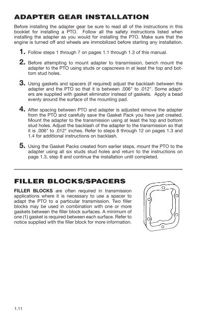
FIlleR blockS/SPAceRS<br />
FILLER BLOCKS are often required in transmission<br />
applications where it is necessary to use a spacer to<br />
adapt the <strong>PTO</strong> to a particular transmission. Two filler<br />
blocks may be used in combination with one or more<br />
gaskets between the filler block surfaces. A minimum of<br />
one (1) gasket is required between each surface. Refer to<br />
notice supplied with the filler block for more information.<br />
1.11