Instructions - Fontaine International
Instructions - Fontaine International
Instructions - Fontaine International

You also want an ePaper? Increase the reach of your titles
YUMPU automatically turns print PDFs into web optimized ePapers that Google loves.
®<br />
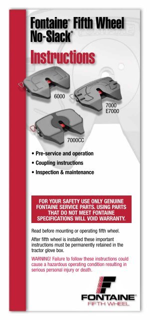
<strong>Fontaine</strong> ®<br />
No-Slack<br />
<strong>Instructions</strong><br />
6000<br />
• Pre-service and operation<br />
• Coupling instructions<br />
• Inspection & maintenance<br />
Fifth Wheel<br />
7000CC<br />
7000<br />
E7000<br />
for your safety use only GenuIne<br />
fontaIne servICe Parts. usInG Parts<br />
that do not meet fontaIne<br />
sPeCIfICatIons wIll voId warranty.<br />
Read before mounting or operating fifth wheel.<br />
After fifth wheel is installed these important<br />
instructions must be permanently retained in the<br />
tractor glove box.<br />
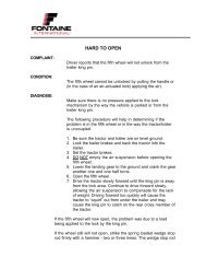
WARNING! Failure to follow these instructions could<br />
cause a hazardous operating condition resulting in<br />
serious personal injury or death.
Introduction<br />
warning!<br />
WARNING! The visual inspection is required by law. Some<br />
improper couplings can pass a “tug test” and sound is<br />
not reliable to verify proper coupling. The coupling<br />
procedure is not complete without a visual inspection. It<br />
is necessary to get out of the tractor and look. Incorrect<br />
coupling could cause the trailer to disconnect, possibly<br />
resulting in serious personal injury or death.<br />
WARNING! When coupling, the fifth wheel must lift the<br />
trailer. Always inflate the tractor suspension air bags<br />
prior to coupling. Coupling should not be attempted with<br />
the tractor suspension air bags deflated. Inflating the<br />
tractor suspension air bags while positioned underneath<br />
the trailer may result in damage to and incorrect<br />
coupling of the fifth wheel, possibly resulting in serious<br />
personal injury or death.<br />
WARNING! Do not use any fifth wheel that has damaged<br />
components or fails to operate properly.<br />
WARNING! Failure to follow these specifications will void<br />
the warranty and could affect product performance.<br />
WARNING! Air cylinder(s) should not be disassembled as<br />
contents are under pressure.<br />
WARNING! Under no circumstances should a sliding fifth<br />
wheel be repositioned while the tractor and trailer are in<br />
motion. This could result in personal injury or death.<br />
WARNING! Do not use a lube plate (high-density<br />
polyethylene) on top of the fifth wheel or kingpin bolster<br />
plate in lieu of grease without prior approval by <strong>Fontaine</strong>.<br />
2
Introduction<br />
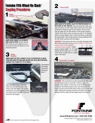
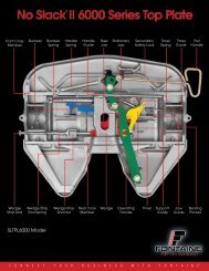
how to tell If the fIfth wheel Is ProPerly loCKed –<br />
no slack ®<br />
Verify secure coupling with a “tug test”, by easing the<br />
tractor forward, with the trailer brakes on, to feel<br />
resistance of the load. Set the parking brakes on the<br />
tractor and trailer and get out of the tractor and visually<br />
inspect, using a flashlight if necessary, that the fifth wheel<br />
is properly closed.<br />
the locking jaw and wedge must be fully across the<br />
throat of the fifth wheel, there must be no gap<br />
between the fifth wheel and the trailer plate, and the<br />
pull handle must be within 1” or less from the skirt of<br />
the fifth wheel. all three areas of the fifth wheel must<br />
be inspected to ensure that the fifth wheel is properly<br />
coupled.<br />
Below are three critical areas of visual inspection that<br />
drivers must perform after every couple.<br />
Kingpin<br />
Wedge<br />
Pull handle<br />
Fifth wheel throat<br />
1" Skirt<br />
Locking jaw<br />
and wedge<br />
must be fully<br />
across the<br />
throat of the<br />
fifth wheel<br />
No gap<br />
between<br />
trailer<br />
bottom and<br />
fifth wheel<br />
Gap between<br />
pull handle<br />
and skirt of<br />
wheel less<br />
than 1”.<br />
If the visual inspection indicates that you failed to<br />
obtain a proper couple, open the fifth wheel, inspect<br />
for damaged components, and repeat the coupling<br />
sequence.<br />
3
Introduction<br />
For over 60 years, <strong>Fontaine</strong> has been passing customer<br />
performance tests by building fifth wheels with<br />
innovative technology, uncompromising quality, and<br />
features designed to ensure cost-efficient performance.<br />
This handbook provides instructions and recommended<br />
procedures to ensure optimum performance from your<br />
new <strong>Fontaine</strong> ® No-Slack ® fifth wheel.<br />
Keep this handbook in the tractor glove box after<br />
your fifth wheel has been installed.<br />
For convenience, record fifth wheel information below:<br />
Model number: ________________________<br />
Serial number: ________________________<br />
In service date: ________________________<br />
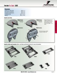
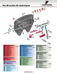
Serial number engraved into the right side of the fifth<br />
wheel skirt. Note: position 5 and 6 of the serial number<br />
indicates the year built.<br />
new (current) style serial number (after<br />
11/27/00). Serial number engraved directly into the<br />
right side of fifth wheel skirt.<br />
no-slack ® right side view<br />
old style serial number (before 11/27/00). Serial<br />
number located on small rectangular tag on front<br />
of top plate.<br />
XXXXXXXXX<br />
no-slack<br />
If you have any questions concerning your new fifth<br />
wheel, our Customer Service Department is available to<br />
help you at (800) 874-9780.<br />
® front view<br />
Note: For warranty information go to:<br />
http://www.fifthwheel.com<br />
Choose “Support” menu and select<br />
"Warranty information.”<br />
For installation information go to:<br />
http://www.fifthwheel.com<br />
Choose “Support” menu and select "Helpful<br />
information.”<br />
4
Contents Pages<br />
Section I – Pre-service and operation . . . . . .5-9<br />
Section II – Coupling instructions . . . . . . .10-20<br />
Section III – Inspection and maintenance . 20-23<br />
section I –<br />
Pre-service and operation<br />
Always check for damage due to improper handling or<br />
delivery practices prior to starting recommended preservice<br />
procedure.<br />
a. fasteners<br />
Make sure all nuts and bolts are in place and<br />
properly tightened.<br />
Check to see if both bracket pins are in place and<br />
secured by retainer pins and cotter pins (see FIGURE 1).<br />
fIGure 1<br />
Bracket pin<br />
Pre-service and operation<br />
5<br />
Retainer pin<br />
Cotter pin
Pre-service and operation<br />
B. lubrication<br />
1. Tilt the top plate forward (front of the fifth wheel down)<br />
and apply grease to each bearing area through the zerk<br />
fitting (No-Slack ® 6000/7000/7000CC/E7000 has two<br />
fittings each side) located on each side of the top plate<br />
just to the front of the bracket pins. Continue to apply<br />
grease until it is coming out of the back of the bearing. It<br />
may be necessary to raise the rear of the fifth wheel with<br />
a pry bar to open up the pocket slightly and allow the<br />
grease to flow through. A substantial amount of grease<br />
may be required initially to fill the reservoir. Tilt the wheel<br />
to the rear (rear of the wheel down) and repeat the<br />
procedure. Rock the top plate back and forth several<br />
times to spread the grease over the bearing surface. If you<br />
have a no lube bracket liner, do not grease.<br />
Inspect the trailer kingpin plate and top surface of the<br />
fifth wheel to make sure each is properly greased. A<br />
liberal coating of grease should be applied to the<br />
complete surfaces of both the trailer kingpin plate and<br />
the top surface of the fifth wheel. A paddle or brush<br />
will make this job easier.<br />
Do not use a lube plate (high density polyethylene) on top<br />
of the fifth wheel or on the kingpin in lieu of grease<br />
without prior approval by <strong>Fontaine</strong> Fifth Wheel. The<br />
additional thickness of this material can prevent the<br />
proper operation of the fifth wheel and can cause a<br />
dangerous condition.<br />
2. Lubricate the fifth wheel prior to opening and closing.<br />
Referring to (see FIGURES 2-5 on next pages), grease the<br />
jaw and wedge on top and bottom. Separate the jaw and<br />
wedge with a large screwdriver and distribute the grease<br />
along the full length of the jaw and wedge mating<br />
surfaces. Open and close the fifth wheel several times to<br />
further distribute the grease.<br />
<strong>Fontaine</strong> suggests the use of a Moly based lubricant such<br />
as Mobilgrease XHP320 or equivalent when applying<br />
lubricant to the locking jaw and wedge.<br />
Lightly oil other moving parts in the fifth wheel. (Areas or<br />
regions that experience extreme and/or prolonged freezing<br />
temperatures should consider using a less viscous<br />
substance such as: 90-weight oil, diesel fuel, kerosene,<br />
motor oil, etc. <strong>Fontaine</strong> suggests contacting your specific<br />
6
lubricant manufacturer for guidelines on mixing<br />
compatibility of any lubricant). In cold weather<br />
applications please refer to technical bulletin TB-008.<br />
Technical bulletins are available at fifthwheel.com under<br />
support menu.<br />
3. For sliding fifth wheels, lightly oil the locking mechanism.<br />
Operate the mechanism (air or manual) several times to<br />
ensure it is functioning properly.<br />
4. Grease the top plate. Spread grease all over the mating<br />
surface of the top plate. Be sure the grease pockets<br />
built into the top plates are full of grease.<br />
C. operation<br />
Pre-service and operation<br />
1. <strong>Fontaine</strong>’s No-Slack ® 6000/7000/7000CC/E7000 &<br />
retractable handle fifth wheels shown in open by a<br />
straight pull on the release handle which releases the<br />
secondary lock automatically as the mechanism<br />
opens (see FIGURE 2 and 3).<br />
fIGure 2 – no-slack ® 6000/7000/7000CC/e7000<br />
7<br />
A<br />
Pull<br />
handle<br />
fIGure 3 – no-slack ® 6000/7000/7000CC/e7000<br />
Retractable handle
Pre-service and operation<br />
2. <strong>Fontaine</strong>’s air actuated No-Slack ® 6000/7000/<br />
7000CC/E7000 air-actuated fifth wheel (see FIGURE<br />
4) open with a release valve located on the dash or<br />
in a lock box mounted on the rear of the cab. To<br />
open, set the tractor parking brake and pull the<br />
release valve. Hold the valve open until the locking<br />
mechanism is locked in the open position. The pull<br />
valve will not activate the air cylinder unless the<br />
tractor parking brakes are set.<br />
3. Close the locking mechanism using a test kingpin<br />
(<strong>Fontaine</strong> part number KIT-NOSLACK-KP). Repeat<br />
several times making sure that all moving parts have<br />
adequate lubrication.<br />
4. The pull handle should always be free of grease or<br />
any substance which could prevent a firm grip,<br />
causing the handle to slip and resulting in injury.<br />
fIGure 4 – no-slack ® 6000/7000/7000CC/e7000<br />
fIGure 5<br />
Jaw<br />
Wedge<br />
8<br />
Separate<br />
jaw and<br />
wedge.<br />
Grease full<br />
length.
d. wedge stop rod setting<br />
Pre-service and operation<br />
Wedge stop rod adjustment is not required as part of<br />
the pre-service procedure. It is set during the final<br />
assembly inspection at our manufacturing facility. At<br />
the first recommended P.M. (90 days or 30,000 miles<br />
whichever comes first) and every 90 days or 30,000<br />
miles there after, the wedge stop rod should be<br />
adjusted per technical Bulletin TB-012.<br />
Note P.M. intervals are recommended based on standard<br />
duty applications. Applications more severe than<br />
standard duty may require different P.M. intervals to<br />
ensure peak performance.<br />
fIGure 6 – no-slack ® 6000/7000/7000CC/e7000<br />
this wedge stop rod can also be used to release<br />
a tight wedge (hard to pull handle) by tapping the<br />
rod with a hammer to release the wedge.<br />
e. Knock-out rod<br />
The knock-out rod requires no adjustment (See<br />
Figure 7) and is used to release a tight wedge (hard<br />
to pull handle) by tapping the rod with a hammer.<br />
figure 7<br />
Wedge stop rod<br />
Knock-out rod<br />
Wedge<br />
9
Coupling instructions<br />
section II –<br />
Coupling instructions<br />
CouPlInG ProCedure:<br />
1. Prior to coupling, inspect the fifth wheel to ensure a<br />
proper operation.<br />
• Examine the mounting assembly for securely fastened<br />
bolts.<br />
• Tilt the fifth wheel up and down to make sure that it<br />
moves freely. Rest the fifth wheel in the proper position<br />
by tilting it to the rear of the tractor and resting<br />
it on the stops.<br />
• Check the surface for a liberal coating of grease.<br />
The indented pockets on top of the fifth wheel act as<br />
a grease reservoir for the top surface and should be<br />
filled with grease.<br />
• If the tractor is equipped with an air sliding fifth<br />
wheel, actuate the air cylinder and check for air<br />
leaks. warnInG: aIr CylInder dIsassemBly<br />
should not Be attemPted.<br />
• The fifth wheel should be in an unlocked position.<br />
When unlocked, the handle should be extended (see<br />
FIGURE 1) and the fifth wheel throat unobstructed. If<br />
the fifth wheel is equipped with a retractable handle,<br />
the handle will not be fully extended. do not try to<br />
CouPle to a Closed fIfth wheel.<br />
fIGure 1 – no-slack ® 6000/7000/7000CC/e7000<br />
10
Coupling instructions<br />
2. The trailer kingpin should also be inspected prior to<br />
coupling. The kingpin plate should be fully reinforced<br />
and of sufficient size to completely cover the fifth<br />
wheel. If the kingpin plate is too narrow, the uncovered<br />
portion of the fifth wheel will collect dirt and<br />
foreign matter. This material may work into the fifth<br />
wheel locking mechanism, causing wear and occasionally<br />
difficult uncoupling. This material can also<br />
cause galling of the fifth wheel and/or kingpin plate.<br />
If the trailer kingpin plate is not fully reinforced, distortion<br />
can result causing:<br />
• Non-uniform loading<br />
• Variation in kingpin length<br />
• Cutting and galling of the fifth wheel or kingpin<br />
plate<br />
If the trailer kingpin plate is distorted enough to<br />
cause any of the conditions listed above, we recommend<br />
that a new plate be installed.<br />
The trailer kingpin plate must be properly greased.<br />
<strong>Fontaine</strong> Fifth Wheels are designed and manufactured<br />
for use with all trailer kingpins that conform to<br />
SAE specifications, SAE J700, February 1993 and<br />
subject to the wear limits of SAE J2228, June 1993.<br />
These specifications cover SAE 2" kingpins only.<br />
The SAE standard kingpin can be checked using the<br />
dimensions given below (see FIGURE 2).<br />
11
Coupling instructions<br />
fIGure 2 sae standard king-pin (SAE J700, FEB 93)<br />
3. Proper tractor/trailer alignment is critical to obtain a<br />
secure coupling and to avoid equipment damage.<br />
Set the trailer brakes and raise the trailer to the<br />
proper height by extending the landing legs. If the<br />
trailer is positioned too high, the kingpin may jump<br />
the fifth wheel throat and locking mechanism altogether.<br />
Resulting damage may include: scoring the<br />
fifth wheel, bending the handle thus preventing the<br />
fifth wheel from properly locking to the kingpin,<br />
bending the kingpin, and other significant damage to<br />
the tractor cab.<br />
Coupling should not be attempted if the trailer is too<br />
low. Costly damage may be incurred to the trailer,<br />
the kingpin, the kingpin plate, the fifth wheel, and the<br />
entire tractor drivetrain (see FIGURE 3).<br />
fIGure 3<br />
Fifth wheel<br />
needs to lift up<br />
trailer.<br />
2.875 ± .005<br />
2.000 ± .005<br />
2.812 ± .015<br />
slowly back into<br />
the trailer until<br />
resistance is felt.<br />
12<br />
1.328<br />
1.250<br />
2.782<br />
2.704 3.354<br />
3.256
Coupling instructions<br />
4. To couple the fifth wheel to the kingpin, be sure the<br />
fifth wheel is positioned so that it tilts down at the<br />
rear and is resting on the stops.<br />
Align the kingpin with the throat of the fifth wheel<br />
and ease the tractor toward the trailer. The trailer<br />
should strike the fifth wheel just at the top of the<br />
approach ramps. The fifth wheel will level with the<br />
kingpin plate and the kingpin should slide up the fifth<br />
wheel throat.<br />
Coupling is complete when the fifth wheel locking<br />
mechanism snaps closed behind the kingpin.<br />
Verify secure coupling with a "tug test," by easing<br />
the tractor forward, with trailer brakes on, to feel<br />
resistance of the load. If the coupling feels secure,<br />
visually inspect the fifth wheel. The jaw and wedge<br />
must be locked in place behind the kingpin, completely<br />
across the throat of the fifth wheel, and the<br />
pull handle must be retracted and securely latched in<br />
the secondary lock.<br />
13
Coupling instructions<br />
warnInG! when coupling, the fifth wheel must lift<br />
the trailer. always inflate the tractor suspension air<br />
bags prior to coupling. Coupling should not be<br />
attempted with the tractor suspension air bags<br />
deflated.<br />
Inflating the tractor suspension air bags while<br />
positioned underneath the trailer may result in<br />
damage to and incorrect coupling of the fifth wheel,<br />
possibly resulting in serious personal injury or death.<br />
warning!<br />
the visual inspection is required by law. some improper<br />
couplings can pass a “tug test” and sound is not reliable<br />
to verify proper coupling. the coupling procedure is not<br />
complete without a visual inspection. It is necessary to<br />
get out of the tractor and look. Incorrect coupling could<br />
cause the trailer to disconnect, possibly resulting in<br />
serious personal injury or death.<br />
14
Coupling instructions<br />
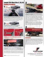
how to tell If the fIfth wheel Is ProPerly loCKed –<br />
no slack ®<br />
Verify secure coupling with a “tug test”, by easing the<br />
tractor forward, with the trailer brakes on, to feel<br />
resistance of the load. Set the parking brakes on the<br />
tractor and trailer and get out of the tractor and visually<br />
inspect, using a flashlight if necessary, that the fifth wheel<br />
is properly closed.<br />
the locking jaw and wedge must be fully across the<br />
throat of the fifth wheel, there must be no gap<br />
between the fifth wheel and the trailer plate, and the<br />
pull handle must be within 1” or less from the skirt of<br />
the fifth wheel. all three areas of the fifth wheel must<br />
be inspected to ensure that the fifth wheel is properly<br />
coupled.<br />
Below are three critical areas of visual inspection that<br />
drivers must perform after every couple.<br />
Kingpin<br />
Wedge<br />
Pull handle<br />
Fifth wheel throat<br />
1" Skirt<br />
Locking jaw<br />
and wedge<br />
must be fully<br />
across the<br />
throat of the<br />
fifth wheel<br />
No gap<br />
between<br />
trailer<br />
bottom and<br />
fifth wheel<br />
Gap between<br />
pull handle<br />
and skirt of<br />
wheel less<br />
than 1”.<br />
If the visual inspection indicates that you failed to<br />
obtain a proper couple, open the fifth wheel, inspect<br />
for damaged components, and repeat the coupling<br />
sequence.<br />
15
Coupling instructions<br />
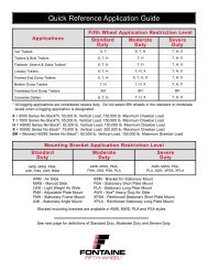
no-slack 7000 series with retractable handle<br />
and visual lock Indicator<br />
7000 Retractable series fifth wheels are equipped with a<br />
retractable handle and an additional lock indicator. The<br />
retractable handle allows the handle to return to the edge<br />
of the skirt after opening. The visual is also available<br />
without the retractable handle.<br />
When coupling the visual lock indictor (see FIGURE 4)<br />
needs to be included in the visually inspection and tug<br />
test as outlined on page 15 to complete the coupling<br />
procedure.<br />
fIGure 4<br />
Fifth wheel closed<br />
Fifth wheel<br />
not closed<br />
A<br />
Note: Lock indicator is extended<br />
and exposed visually indicating<br />
the fifth wheel is locked.<br />
Note: Lock<br />
indicator is<br />
retracted and<br />
not exposed<br />
visually indicating the fifth<br />
wheel is NOT locked.<br />
16
Coupling instructions<br />
no-slack e7000/e7000CC series smartlock<br />
E7000/E7000CC Series fifth wheels are equipped with<br />
internal sensors to detect components in the fifth wheel<br />
that confirm a proper couple. When installed and<br />
powered, a visual indicator on either a display box or<br />
integrated into the dash shows the status of the fifth<br />
wheel lock.<br />
the dash indication provides an extra check to<br />
supplement the driver's visual inspection and pull<br />
test as outlined on page 15.<br />
fIGure 5<br />
fIGure 6<br />
logic box<br />
When the fifth wheel is ready to<br />
couple the “unlocked” indicator is<br />
illuminated in red (see FIGURE 5).<br />
If this is flashing, check to make<br />
sure fifth wheel is open prior to<br />
attempting couple.<br />
When coupled a “locked” indicator<br />
(see FIGURE 6) in green illuminates<br />
and now can be verified with a “tug<br />
test” and visual inspection (refer to<br />
previous page).<br />
For all other troubleshooting, refer to<br />
TB-042 or the operator’s manual for<br />
the integrated instrumentation.<br />
17<br />
sensors
Coupling instructions<br />
slIde adJustment<br />
under no circumstances should a sliding fifth wheel<br />
be repositioned while the tractor and trailer are in<br />
motion. this could result in serious personal injury or<br />
death.<br />
do not attempt to slide the fifth wheel until all<br />
persons are clear of the vehicle.<br />
note: the fifth wheel must be in the locked position<br />
when changing slide positions.<br />
To position an air sliding fifth wheel:<br />
1. Set the trailer brakes.<br />
2. Unlock the cab control air valve and allow the air<br />
cylinder to retract the locking wedges.<br />
3. Ease the tractor forward or backward to move the<br />
fifth wheel to the desired position.<br />
4. Lock the air valve.<br />
warning!<br />
After the fifth wheel is properly positioned, inspect<br />
the locking wedges to ensure that they are fully<br />
engaged in the slide rail pockets. (see FIGURE 9)<br />
figure 9<br />
Wedges through rail<br />
18
unCouPlInG ProCedure:<br />
1. Prior to uncoupling, set the trailer parking brakes.<br />
Back the tractor gently against the trailer. This will<br />
release the load on the fifth wheel locking mechanism.<br />
If the truCK has an aIr susPensIon, do not<br />
dumP the aIr Before oPenInG the fIfth<br />
wheel. doInG so may Cause a hard to oPen<br />
sItuatIon.<br />
2. Block the trailer wheels. If poor ground conditions<br />
exist you may have to provide a base for the trailer<br />
landing gear.<br />
3. Lower landing gear until it contacts the ground. Give<br />
extra turns to reduce load on fifth wheel. do not<br />
raIse traIler off of the fIfth wheel.<br />
4. Disconnect air lines and open the fifth wheel.<br />
5. Slowly drive tractor from under trailer.<br />
Coupling instructions<br />
section III –<br />
Inspection and maintenance<br />
procedures<br />
warnInG! do not use any fifth wheel that has<br />
damaged components or fails to operate properly.<br />
<strong>Fontaine</strong> recommends that preventative maintenance be<br />
performed after 90 days or 30,000 miles, whichever<br />
comes first and every 90 days or 30,000 miles thereafter.<br />
Note: P.M. intervals are recommended based on standard<br />
duty applications. Applications more severe than standard<br />
duty may require different P.M. intervals to ensure peak<br />
performance.<br />
Using a suitable solvent, degrease the fifth wheel and<br />
mounting brackets and inspect for:<br />
1. Cracks in the fifth wheel assembly, mounting brackets,<br />
and mounting parts.<br />
2. Wear and/or damage to moving parts.<br />
3. Loose nuts and bolts in the fifth wheel and in the<br />
mounting hardware.<br />
19
Inspection and maintenance procedures<br />
4. Securely fastened and properly working springs.<br />
5. Check to see if both bracket pins are in place and<br />
secured by retainer pins and cotter pins.<br />
6. Free front to rear rock on brackets with greaseless liners.<br />
If the fifth wheel does not rock freely, remove the<br />
top plate and inspect the bracket<br />
liners. Replace liners that are broken or have worn<br />
excessively. Check the bracket liner thickness at<br />
every scheduled maintenance. Replace liners if the<br />
thickness is less than .125" at the top of the liners.<br />
7. Proper operation of the slide locking mechanism.<br />
Check for air leaks in the cylinder and supply line.<br />
8. Wedge stop rod setting: Close the fifth wheel using a<br />
test kingpin (<strong>Fontaine</strong> part number KIT-NOSLACK-KP).<br />
Push on the wedge stop rod.<br />
(Extends from the side of the top plate and looks like<br />
the head of a bolt). It should move in 1/4" with hand<br />
pressure, then spring back. To obtain a proper setting,<br />
turn the wedge stop rod clockwise to reduce the<br />
dimension and counter-clockwise to increase it. Adjust<br />
until the free travel is 1/4" (see FIGUREs 1 and 2).<br />
This will allow the automatic slack adjustment feature<br />
of the <strong>Fontaine</strong> fifth wheel to function properly.<br />
fIGure 1 – no-slack ® 6000/7000/7000CC<br />
Wedge stop rod<br />
Wedge<br />
fIGure 2 – wedge stop rod setting<br />
20<br />
Close the<br />
fifth wheel<br />
on a 2"<br />
kingpin<br />
Wedge<br />
stop rod
Inspection and maintenance procedures<br />
lubrication<br />
Follow the instructions provided in the Pre-Service<br />
Procedure on pages 5-9.<br />
Periodically remove the fifth wheel to clean old grease<br />
from the bracket grease channels to help insure an even<br />
grease distribution of fresh grease.<br />
Special precautions should be taken during cold weather<br />
to ensure that the <strong>Fontaine</strong> No-Slack ® locking<br />
mechanisms operate freely. Ice and sludge can build up<br />
and lubricants become thick and binding at low<br />
temperatures. When the temperature drops below<br />
freezing, <strong>Fontaine</strong> recommends a thorough cleaning of<br />
the latching mechanism using a suitable cleaner or<br />
degreaser to make sure that all moving parts operate<br />
freely. Lubricate the fifth wheel prior to opening and<br />
closing (see FIGURE 4 on next page). Grease the jaw and<br />
wedge on top and bottom. Separate the jaw and wedge<br />
with a large screwdriver and distribute the grease along<br />
the full length of the jaw and wedge mating surfaces.<br />
Open and close the fifth wheel several times to further<br />
distribute the grease.<br />
fontaine suggests the use of a moly based lubricant<br />
such as mobilgrease XhP320 or equivalent when<br />
applying lubricant. (areas or regions that experience<br />
extreme and/or prolonged freezing temperatures<br />
should consider using a less viscous substance such<br />
as: 90-weight oil, diesel fuel, kerosene, motor oil, etc.<br />
doing so will help ensure proper movement/<br />
lubrication of the latching mechanism. fontaine<br />
suggests contacting your specific lubricant<br />
manufacturer for guidelines on coldmixing<br />
compatibility of any lubricant. In cold weather<br />
applications please refer to technical bulletin tB-008.<br />
technical bulletins are available at fifthwheel.com<br />
under support menu).<br />
The regular performance of the routine, "90-Day/ 30,000<br />
Mile Preventative Maintenance Procedure," is also<br />
recommended.<br />
21
Grease<br />
fittings<br />
Inspection and maintenance procedures<br />
fIGure 4<br />
Clean oil/grease all moving parts (arrows)<br />
Jaw<br />
Wedge<br />
Jaw &<br />
wedge<br />
Separate jaw and wedge with screwdriver<br />
here – grease full length.<br />
22<br />
Grease<br />
fittings
for sales and service locations or for<br />
additional copies of this handbook go<br />
www.fifthwheel.com or contact fontaine<br />
Customer support at 1-800-874-9780.<br />
23
<strong>Fontaine</strong> Fifth Wheel<br />
7574 Commerce Circle • Trussville, AL 35173 USA<br />
800.874.9780 • Fax 205.655.9982<br />
www.fifthwheel.com<br />
©2012 <strong>Fontaine</strong> Fifth Wheel • LT-001 • November 2012<br />
All specifications are subject to change without notice.