Service Manual - Fontaine International
Service Manual - Fontaine International
Service Manual - Fontaine International

You also want an ePaper? Increase the reach of your titles
YUMPU automatically turns print PDFs into web optimized ePapers that Google loves.
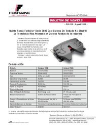
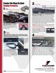
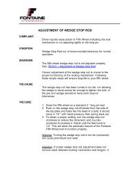
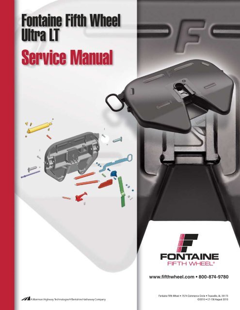
<strong>Fontaine</strong> Fifth Wheel<br />
Ultra LT<br />
<strong>Service</strong> <strong>Manual</strong><br />
FONTAINE<br />
FIFTH WHEEL ®<br />
www.fifthwheel.com • 800-874-9780<br />
<strong>Fontaine</strong> Fifth Wheel • 7574 Commerce Circle • Trussville, AL 35173<br />
©2010 • LT-156 August 2010
2<br />
Ultra LT<br />
Contents<br />
Identify your fifth wheel ....................................... 2-3<br />
Slides and brackets ............................................. 4-5<br />
Pre-service procedures ........................................ 6-8<br />
Preventive maintenance ..................................... 9-10<br />
Uncoupling design ........................................... 11-12<br />
Troubleshooting ............................................... 13-15<br />
Rebuild ............................................................ 16-18<br />
Disassembly .................................................... 19-20<br />
Assembly ......................................................... 21-22<br />
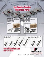
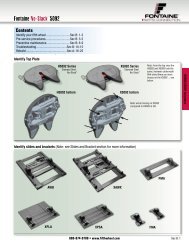
Identify fifth wheel assembly<br />
Identify top plate<br />
Indentifying features:<br />
• Fabricated pull handle<br />
• Slide assemblies have centermounted<br />
air cylinders<br />
• Name tags located on front skirt<br />
Identify slides and brackets (Note: see Slides and Bracket section for more information)<br />
Inboard models<br />
will be available<br />
in the future<br />
Inboard<br />
Adjustable plate mount<br />
800-874-9780 • www.fifthwheel.com<br />
Outboard<br />
FONTAINE<br />
FIFTH WHEEL ®<br />
Ultra LT Series
Identify your fifth wheel<br />
Serial number locations<br />
Serial number engraved directly into the right of fifth wheel skirt.<br />
Note: position 5 and 6 of the serial number indicates the year built.<br />
Part number nomenclature<br />
<strong>Fontaine</strong> Fifth Wheel complete assembly part numbers. Example: SL4LWO675012<br />
FONTAINE<br />
FIFTH WHEEL ®<br />
1. Top plate 2. Mounting bracket 3. Slide rail<br />
SL Release 4 Top plate model LWO Mounting bracket 6750 Mounting height 12 Slide travel<br />
SL = Side left<br />
SR = Side right<br />
AA = Air actuated<br />
Duty class restrictions<br />
4 = Ultra LT Series LWO = Outboard slide bracket Actual height from truck<br />
APB = Adjustable plate bracket<br />
Pending release:<br />
LWI = Inboard slide bracket<br />
SMB = Stationary bracket mount<br />
A36 = Angle mount<br />
Application/restriction levels<br />
Standard duty: Fifth Wheel must be used in a 100% on-highway<br />
application, with more than 30 miles between each stop. The<br />
total number of towed axles equals two (2). Road type must be<br />
maintained concrete or asphalt. Gross Combination Weight (GCW)<br />
is less than 95,000 lbs or 43,000 kgs. See <strong>Fontaine</strong> Application<br />
Guide LT-076 for specific application recommendations. Product<br />
used in unapproved applications voids manufacture warranty.<br />
Moderate duty: Fifth Wheel must be used in a less than 10%<br />
off-highway application, with no minimum mileage between each<br />
stop. The maximum total number of towed axles equals four (4).<br />
Road type must be maintained concrete, asphalt, gravel, or crushed<br />
rock. Gross Combination Weight (GCW) is less than 115,000 lbs<br />
or 52,000 kgs. See <strong>Fontaine</strong> Application Guide LT-076 for specific<br />
application recommendations. Product used in unapproved<br />
applications voids manufacture warranty.<br />
Severe duty: Fifth Wheel can be used in any off-highway<br />
application, with no minimum mileage between each stop. The<br />
total number of towed axles equals five (5) or more. All road types<br />
are acceptable including hard packed dirt and non-maintained<br />
roads. Gross Combination Weight (GCW) is more than 115,000 lbs<br />
or 52,000 kgs. See <strong>Fontaine</strong> Application Guide LT-076 for specific<br />
application recommendations. Product used in unapproved<br />
applications voids manufacture warranty.<br />
frame to top of fifth wheel.<br />
Examples: 6750 = 6-3/4"<br />
7750 = 7-3/4"<br />
8750 = 8-3/4"<br />
For sliding fifth wheels only.<br />
Example: 12 = 12" slide<br />
24 = 24" slide<br />
36 = 36" slide<br />
48 = 48" slide<br />
Important application notes:<br />
1. If any single restriction factor within your application<br />
is surpassed within a given duty level, the next duty<br />
level must be selected.<br />
2. When selecting a fifth wheel, if the application or<br />
vehicle usage places the maximum capacity on a<br />
certain fifth wheel, then the selection of a fifth wheel<br />
with a higher capacity is advised. For example, a<br />
tractor that is at a maximum vertical load of 50,000<br />
lbs in a moderate duty application should be using a<br />
fifth wheel with a vertical load capacity of 55,000 lbs<br />
or greater. This additional capacity should give better<br />
service life over a longer period of time.<br />
3. All logging, mining, oil field and similar applications<br />
are considered severe duty. Do not select assemblies<br />
in the standard or moderate levels when a special<br />
application is designated.<br />
800-874-9780 • www.fifthwheel.com 3
<strong>Fontaine</strong> ®<br />
Ultra LT Series Slides and Brackets<br />
1<br />
4<br />
6<br />
8<br />
9<br />
7<br />
4<br />
5<br />
10<br />
11<br />
8<br />
3<br />
7<br />
Item Description Part No. Quantity<br />
1 Slide Rail * 1<br />
2<br />
9<br />
6<br />
10<br />
11<br />
800-874-9780 • www.fifthwheel.com<br />
2<br />
4<br />
FONTAINE<br />
FIFTH WHEEL ®<br />
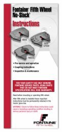
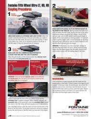
LWO: Outboard slide<br />
• Up to 50 lbs lighter than competitive outboard<br />
slide systems<br />
• 4” slide increments give you slide versatility for<br />
improved payload distribution<br />
• Compact design with central mounted air cylinder<br />
• Booted air cylinder provides protection to shaft<br />
• Available in 6-3/4", 7-3/4", 8-3/4" and 9-3/4"<br />
heights; 12”, 16", 24”, 36” and 48” slide travel<br />
LWO parts list<br />
Item<br />
no.<br />
LWO weight chart<br />
Slide<br />
Height<br />
Length 6-3/4" 7-3/4" 8-3/4" 9-3/4"<br />
12" 356 lbs 361 lbs 367 lbs 373 lbs<br />
16" 363 lbs 368 lbs 374 lbs 380 lbs<br />
24" 376 lbs 381 lbs 387 lbs 393 lbs<br />
36" 396 lbs 401 lbs 407 lbs 413 lbs<br />
48" 416 lbs 421 lbs 427 lbs 433 lbs<br />
Add 5 lbs for air actuation<br />
Description Part no. Qty.<br />
1 Slide rail – 1<br />
2 Rear slide stop – 2<br />
3 Slide bracket – 1<br />
4 Bracket bushing BSH-3000 2<br />
5 Air cylinder * 1<br />
6 Locking wedge – 2<br />
7 Hex bolt, 3/8"-16 x 1-1/4", gr5 * 2<br />
8 Spacer bushing * 2<br />
9 Hex lock nut, 3/8"-16, gr5 * 2<br />
10 Flat washer, 1/2" – 2<br />
11 Hex head bolt, 1/2"-13 x 1" – 2<br />
* Included in LWO/LWI air cylinder kit, part no.:<br />
CYL-LWO-LWI
<strong>Fontaine</strong> ®<br />
Ultra LT Series Slides and Brackets<br />
FONTAINE<br />
FIFTH WHEEL ®<br />
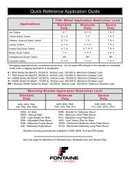
APB: Adustable plate mount<br />
• LT top plate with the ABP bracket is the lightest<br />
mounting system available for the LT family<br />
• Manufactured with the durability and costeffectiveness<br />
of steel construction<br />
• Brackets are welded to a 3/8" steel plate with<br />
six 5/8" bolt holes on each side for mounting<br />
versatility<br />
• Plate has different cut out and different locations<br />
for rear rocker limit blocks<br />
• Available in 6-1/4", 7-1/4", 8-1/4" and 9-1/4"<br />
heights<br />
APB weight chart<br />
Height<br />
6-1/4" 7-1/4" 8-1/4" 9-1/4"<br />
281 lbs 286 lbs 291 lbs 297 lbs<br />
800-874-9780 • www.fifthwheel.com 5
Pre-service procedures<br />
Always check for damage due to improper handling or<br />
delivery practices prior to starting recommended pre-service<br />
procedure.<br />
A. Fasteners<br />
Make sure all nuts and bolts are in place and properly<br />
tightened.<br />
Check all welds for cracks, breaks or separation.<br />
Check to see if both bracket pins are in place and secured by<br />
retainer pins and cotter pins.<br />
See Figure A and B.<br />
6<br />
Figure A<br />
Figure B<br />
Cotter pin<br />
Retainer pin<br />
Bracket pin<br />
B. Lubrication<br />
800-874-9780 • www.fifthwheel.com<br />
FONTAINE<br />
FIFTH WHEEL ®<br />
1. Tilt the top plate forward (front of the fifth wheel down) and<br />
apply grease to each bearing area through the zerk fitting<br />
located on each side of the top plate just to the front of the<br />
bracket pins. Continue to apply grease until it is coming out of<br />
the back of the bearing. It may be necessary to raise the rear<br />
of the fifth wheel with a pry bar to open up the pocket slightly<br />
and allow the grease to flow through. Periodically remove<br />
the fifth wheel to clean old grease from the bracket grease<br />
channels to help insure an even distribution of fresh grease.<br />
A substantial amount of grease may be required initially to<br />
fill the reservoir. Tilt the wheel to the rear (rear of the wheel<br />
down) and repeat the procedure. Rock the top plate back<br />
and forth several times to spread the grease over the bearing<br />
surface.<br />
Inspect the trailer kingpin plate and top surface of the fifth<br />
wheel to make sure each is properly greased. A liberal coating<br />
of grease should be applied to the complete surfaces of both<br />
the trailer kingpin plate and the top surface of the fifth wheel.<br />
A paddle or brush will make this job easier.<br />
Do not use a lube plate (high density polyethylene) on top<br />
of the fifth wheel or kingpin bolster plate in lieu of grease<br />
without prior approval by <strong>Fontaine</strong>.<br />
The additional thickness of this material can prevent the<br />
proper operation of the fifth wheel and can cause a dangerous<br />
condition.<br />
2. Lubricate the fifth wheel lock prior to opening and closing.<br />
Referring to Figure C, grease the jaw and lockbar (wedge) on<br />
top and bottom. Separate the jaw and lockbar (wedge) with<br />
a large screwdriver and distribute the grease along the full<br />
length of the jaw and lockbar (wedge) mating surfaces. Open<br />
and close the fifth wheel several times to further distribute the<br />
grease.<br />
Figure C<br />
Grease<br />
fitting<br />
Separate jaw and<br />
wedge – grease<br />
full length<br />
Jaw<br />
Grease<br />
fitting<br />
Wedge
Pre-service procedures<br />
<strong>Fontaine</strong> suggests the use of a moly-based lubricant such as<br />
Mobilgrease XHP320 or equivalent when applying lubricant<br />
to the locking jaw and wedge. Lightly oil other moving parts<br />
in the fifth wheel (areas or regions that experience extreme<br />
and/or prolonged freezing temperatures should consider<br />
using a less viscous substance such as: 90-weight oil, diesel<br />
fuel, kerosene, motor oil, etc. <strong>Fontaine</strong> suggests contacting<br />
your specific lubricant manufacturer for guidelines on mixing<br />
compatibility of any lubricant).<br />
3. For sliding ffth wheels, lightly oil the locking mechanism.<br />
Operate the mechanism several times to ensure it is<br />
functioning properly.<br />
4. Grease the top plate. Spread grease all over the mating<br />
surface of the top plate. Be sure the grease pockets built into<br />
the top plates are full of grease.<br />
C. Operation<br />
1. <strong>Fontaine</strong>’s Ultra LT fifth wheel opens by a straight pull<br />
on the release handle until maximum opening stroke is<br />
achieved then is moved slightly forward until the handle cut<br />
out sets up on the handle block located on the fifth wheel<br />
skirt.<br />
2. Close the locking mechanism using a test kingpin or 2"<br />
(50.8 mm) diameter pipe. Repeat several times making sure<br />
that all moving parts have adequate lubrication.<br />
3. The pull handle grip should always be free of grease or<br />
any substance which could prevent a firm grip, causing the<br />
handle to slip and possibly resulting in injury.<br />
4. <strong>Fontaine</strong>’s air actuated Ultra LT fifth wheel is shown in<br />
Figure D. A release valve located on the dash or in a lock<br />
box mounted on the rear of the cab is used to activate the<br />
release cylinder. To open, set the tractor parking brake and<br />
pull the release valve. Hold the valve open until the locking<br />
mechanism is locked in the open position. The pull valve<br />
will not activate the air cylinder unless the tractor parking<br />
brakes are set.<br />
Figure D<br />
FONTAINE<br />
FIFTH WHEEL ®<br />
Note: This lock is set from the factory with some running<br />
slack based on a two inch kingpin. If a kingpin is less<br />
than nominal diameter but within tolerance of SAE 1955<br />
the amount of slack will increase. No attempt should be<br />
made to reduce the slack on smaller diameters kingpins<br />
as it would result in failure to close properly around a<br />
nominal kingpin diameter. The adjustment stud can<br />
not be used as knock-out rod! If the fifth wheel is not<br />
properly adjusted the wheel will be very difficult to open.<br />
Once the wheel is opened the adjustment procedure<br />
should be followed by installing a 2" kingpin and the<br />
adjustment stud should receive 2-1/2 turns after contact<br />
with the lock bar.<br />
800-874-9780 • www.fifthwheel.com 7
Pre-service procedures<br />
8<br />
800-874-9780 • www.fifthwheel.com<br />
FONTAINE<br />
FIFTH WHEEL ®<br />
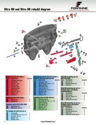
Lubrication points: (Ultra LT)<br />
Black arrows are lube points when the fifth wheel is on a mount. However, for proper maintenance it is recommended you clean it<br />
and re-grease the pivot points... see white arrows.<br />
Jaw and wedge<br />
(see preservice and<br />
lubrication)
Preventive maintenance<br />
Remember to exercise extreme caution, follow all stated<br />
& customary safety procedures, and be sure to wear<br />
safety glasses.<br />
Step 1. Visual inspection<br />
Using a suitable solvent, degrease the fifth wheel and<br />
mounting brackets every 90 days or 30,000 miles and<br />
inspect for:<br />
1. Cracks in the fifth wheel assembly, mounting brackets,<br />
and mounting parts.<br />
2. Wear and/or damage to moving parts.<br />
3. Correct operation of the secondary lock.<br />
4. Loose nuts and bolts in the fifth wheel and in the<br />
mounting hardware.<br />
5. Securely fastened and properly working springs.<br />
6. Check to see if both bracket pins are in place and<br />
secured by retainer pins and cotter pins.<br />
7. Check the locking jaw. If dimension “X” is less than 0.8"<br />
(20.25 mm) replacement of the jaw and lockbar (wedge)<br />
is required. See Figure A.<br />
Figure A<br />
Dimension “X”<br />
Check the fifth wheel operation and adjustment. Using a<br />
test kingpin or 2" (50.88 mm) diameter pipe, follow the<br />
instructions provided in the pre-service procedure on<br />
pages 6-8.<br />
Step 2. Function Inspection<br />
FONTAINE<br />
FIFTH WHEEL ®<br />
Begin with the fifth wheel in the unlocked position. Pull<br />
handle to unlock fifth wheel if it is not open.<br />
Insert a test kingpin, such as <strong>Fontaine</strong> Kingpin Tool<br />
KIT-ULTRA-KP, to close the lock.<br />
Make sure the jaw and wedge are engaged behind the<br />
kingpin and the pull handle is fully retracted.<br />
Open and close the wheel again.<br />
If the action is slow or sluggish, it may be due to a build up<br />
of old grease or a bent part causing binding (see trouble<br />
shooting section).<br />
Lightly lubricate the pivot points on the mechanism with a<br />
spray lubricant.<br />
Step 3. Adjustment<br />
1. With the wheel in the closed position, loosen the<br />
adjuster lock nut and turn the adjuster stud counter<br />
clockwise (outward) until it is free from touching the end<br />
of the lockbar (wedge).<br />
2. Insert a test kingpin or 2" (50.8 mm) diameter shaft to<br />
ensure the locking mechanism is completely closed.<br />
3. Turn the adjuster stud clockwise (inward) until it<br />
contacts the end of the lockbar (wedge). Now turn the<br />
adjuster stud clockwise (inward) an additional 2-1/2<br />
revolutions. This will give the recommended .02"<br />
(0.525 mm) running clearance.<br />
4. Tighten the adjuster lock nut.<br />
Improper adjustment can cause the mechanism to bind<br />
and/or wear prematurely.<br />
800-874-9780 • www.fifthwheel.com 9
Preventive maintenance<br />
Step 4. Lubrication<br />
Lubrication recommended every 6 weeks or 15,000<br />
miles.<br />
Follow the instructions provided in the lubrication<br />
pre-service procedures on pages 6-7.<br />
Special precautions must be taken during cold weather<br />
to ensure that the <strong>Fontaine</strong> Ultra LT locking mechanism<br />
operates freely. Ice and sludge can built up and lubricants<br />
become thick and binding at low temperatures. In areas or<br />
regions that experience extreme and/or prolonged freezing<br />
temperatures, <strong>Fontaine</strong> recommends use of a cleaner or<br />
degreaser on the latching mechanism, making sure that the<br />
moving parts operate freely. This should be followed by an<br />
application of 90-weight oil, diesel fuel, kerosene, motor<br />
oil, etc. to all moving parts. This procedure may also be<br />
necessary in operations where excessive road grime or grit<br />
is encountered.<br />
The regular performance of the routine, "90-Day/30,000<br />
mile preventative maintenance procedure," is also<br />
recommended.<br />
10<br />
800-874-9780 • www.fifthwheel.com<br />
FONTAINE<br />
FIFTH WHEEL ®
Uncoupling design<br />
1.<br />
Lockbar<br />
Adjustment<br />
stud<br />
Lockbar (wedge) is stopped by the adjustment stud.<br />
Springs apply constant pressure to hold the wedge tight<br />
against the stud. Proper adjustment allows the wedge from<br />
becoming “wedged” behind the jaw.<br />
3.<br />
Handle is pulled until notch is free to be placed on the latch<br />
catch block on the handle plate (not shown). Trailer holds<br />
the kingpin the jaw in the fifth wheel. There is a portion of<br />
the lockbar that is in the throat of the fifth wheel.<br />
2.<br />
FONTAINE<br />
FIFTH WHEEL ®<br />
First pull of the handle rotates the secondary lock to clear<br />
the secondary lock stop.<br />
4.<br />
As trailer pulls the kingpin away from the stationary jaw,<br />
the rotating jaw moves. The kingpin then contacts the<br />
lockbar that is the throat.<br />
800-874-9780 • www.fifthwheel.com 11
Uncoupling design<br />
5. 6.<br />
As trailer continues to pull the kingpin out of the fifth<br />
wheel, jaw rotates until it hits stop on cover plate. The<br />
kingpin pushes the lockbar allowing the notch to become<br />
free of the lock catch. The springs rotate the handle away<br />
from the lock catch allowing the fifth wheel to become<br />
set-up for the next couple.<br />
12<br />
Visual lock indicators<br />
Fifth wheel is not closed since handle<br />
notch is not over the handle plate.<br />
800-874-9780 • www.fifthwheel.com<br />
FONTAINE<br />
FIFTH WHEEL ®<br />
Fifth wheel is ready to couple. There is some portion of the<br />
lockbar in the throat of the fifth wheel.<br />
Fifth wheel is locked as shown by the handle<br />
notch being over the handle plate.
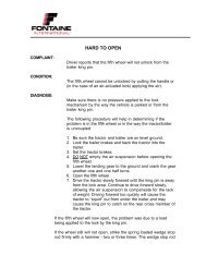
Troubleshooting<br />
NO<br />
Check for obstruction<br />
hitting between fifth wheel<br />
and mounting base.<br />
Check kingpin for<br />
proper dimension.<br />
Check for correct<br />
adjustment setting.<br />
Hard to open<br />
Ultra LT<br />
Will the<br />
pull handle move?<br />
Check for proper lubrication.<br />
Check for obstruction<br />
hitting between fifth wheel<br />
and mounting base.<br />
Check kingpin for<br />
proper dimension.<br />
Check for proper rotation<br />
of secondary lock.<br />
Do not over tighten.<br />
Check for damaged<br />
pull handle spring.<br />
Check for damaged components such<br />
as pull handle, operating handle,<br />
cover plate, rotating locking jaw and<br />
secondary lock spring.<br />
Finish or call<br />
<strong>Fontaine</strong> Parts Connection.<br />
YES<br />
NO<br />
Make sure fifth wheel is<br />
in open position.<br />
Make sure kingpin is<br />
at correct height.<br />
Hard to close<br />
Ultra LT<br />
While<br />
coupling, does handle<br />
retract at all?<br />
Check for bent pull handle and/or<br />
operating handle base.<br />
Check tip of rotating jaw to see<br />
if worn, broken or bent.<br />
Check kingpin to see<br />
if bent or worn.<br />
Check to see if cover plate<br />
is bent or broken.<br />
FONTAINE<br />
FIFTH WHEEL ®<br />
Check for interference<br />
between top plate and<br />
base mount.<br />
Check to see if operating handle spring<br />
or pull handle rotating jaw spring is<br />
missing or damaged.<br />
Finish or call<br />
<strong>Fontaine</strong> Parts Connection.<br />
800-874-9780 • www.fifthwheel.com 13<br />
YES
Troubleshooting<br />
14<br />
Set adjustment<br />
rod to proper<br />
setting.<br />
NO<br />
Is<br />
adjustment<br />
rod set correctly?<br />
Check for bent operating<br />
handle and/or pull handle.<br />
Check for bent or damaged<br />
cover plate and/or<br />
rotating locking jaw.<br />
Check for bent or damaged<br />
pull handle spring, operating<br />
handle spring and/or rotating<br />
jaw spring.<br />
Finish or call<br />
<strong>Fontaine</strong> Parts Connection.<br />
Excessive slack<br />
Ultra LT<br />
Is the<br />
wheel completely<br />
closed?<br />
YES<br />
Is<br />
adjustment<br />
rod set correctly?<br />
NO NO<br />
YES<br />
YES<br />
Set adjustment<br />
rod to proper<br />
setting.<br />
Check for kingpin wear.<br />
Check rotating locking jaw<br />
and wedge for wear.<br />
Check for bent or damaged<br />
cover plate and/or<br />
rotating locking jaw.<br />
Finish or call<br />
<strong>Fontaine</strong> Parts Connection.<br />
NO<br />
Check for interference<br />
between top plate and<br />
mount or other lower frame<br />
obstruction.<br />
800-874-9780 • www.fifthwheel.com<br />
Will not latch open<br />
Ultra LT<br />
Have<br />
you checked for<br />
interference between<br />
wheel and base<br />
mount?<br />
Check for missing or damaged<br />
operating handle, pull handle or<br />
rotating jaw springs.<br />
Check for bent pull handle, operating<br />
handle or cover plate.<br />
Check for worn or broken<br />
rotating lock jaw.<br />
Check for excessive wear on<br />
pull handle notch and/or<br />
fifth wheel latch block.<br />
Check for proper orientation of pull<br />
handle and secondary lock.<br />
Make sure pull handle bolt<br />
is not too tight.<br />
Finish or call<br />
<strong>Fontaine</strong> Parts Connection.<br />
FONTAINE<br />
FIFTH WHEEL ®<br />
YES
Troubleshooting<br />
NO<br />
Air Actuated coupling problems<br />
Ultra LT<br />
Remove air cylinder and<br />
check for damage - i.e. bent<br />
shaft, exterior housing or<br />
broken internal spring.<br />
Is air<br />
supply line crushed<br />
or crimped?<br />
Finish or call<br />
<strong>Fontaine</strong> Parts Connection.<br />
Check air cylinder port<br />
and/or relief valve hole for<br />
obstruction.<br />
Replace air line.<br />
NO<br />
NO<br />
Is the wheel closing<br />
properly?<br />
Check air cylinder for leakage.<br />
Is air<br />
cylinder installed<br />
properly?<br />
YES<br />
Check air supply line<br />
for damage (crushed or<br />
crimped).<br />
YES<br />
Remove air cylinder and<br />
check for damage i.e. bent<br />
shaft, exterior housing or<br />
broken internal spring.<br />
Finish or call<br />
<strong>Fontaine</strong> Parts Connection.<br />
FONTAINE<br />
FIFTH WHEEL ®<br />
800-874-9780 • www.fifthwheel.com 15
Rebuild<br />
Items needed for rebuild (follow rebuild<br />
instructions included in the LT-147)<br />
Remember to exercise extreme caution, follow all<br />
stated and customary safety procedures, and be<br />
sure to wear safety glasses.<br />
Do not use pneumatic tools. Over-tightening may<br />
cause damage.<br />
• 15/16" wrench<br />
• 3/4" socket wrench<br />
• Pliers<br />
• Flat head screw driver<br />
• Long pry bar<br />
• Test kingpin KIT-ULTRA-KP<br />
• Kingpin gauge MSC-GAUGE<br />
• Moly-based lubricant such as Mobilgrease XHP320 or<br />
equivalent<br />
16<br />
800-874-9780 • www.fifthwheel.com<br />
FONTAINE<br />
FIFTH WHEEL ®<br />
Inspect fifth wheel for damage<br />
Before rebuilding check to make sure that there are no cracks in the crossmembers or other components. Under no circumstances should a<br />
fifth wheel be repaired or used if any component (cross member, saddle bearing, etc.) is cracked. Also check for excessively worn areas.<br />
Special tools<br />
KIT-ULTRA-KP<br />
Top plate rebuild kit<br />
KIT-RPR-UL-L<br />
After inspection you may need to optionally order other kits. See<br />
schematic on page18.<br />
<strong>Fontaine</strong> offers special tools for your fifth<br />
wheel to help your repairs go fast and easy.<br />
Kingpin gauge<br />
MSC-GAUGE
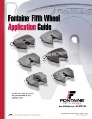
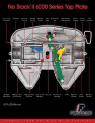
Rebuild<br />
Ultra LT series part identification<br />
Cover plate not shown for clarity.<br />
Bracket<br />
liner<br />
Adjustment<br />
rod<br />
Jaw<br />
spring<br />
Adjustment<br />
rod nut<br />
Main<br />
springs<br />
Pivot<br />
pin<br />
Rotating locking<br />
jaw<br />
Pivot pin<br />
clip<br />
Locking<br />
wedge<br />
Hex head bolt &<br />
lock nut<br />
Operating<br />
handle<br />
Pull<br />
handle<br />
Pivot pin<br />
clip<br />
FONTAINE<br />
FIFTH WHEEL ®<br />
Pivot<br />
pin<br />
short<br />
800-874-9780 • www.fifthwheel.com 17
Rebuild<br />
18<br />
9<br />
8<br />
2<br />
3<br />
10<br />
1<br />
11<br />
6<br />
Repair kit (KIT-RPR-UL-L)<br />
Item Description Quantity<br />
7 Pivot pin, long 1<br />
20 Pivot pin, short 1<br />
25 Lock nut, 5/8"-11 1<br />
26 Main spring 2<br />
27 Jaw spring 1<br />
28 Rotating locking jaw 1<br />
29 Pivot pin clip 2<br />
30 Locking wedge 1<br />
32 Washer, 3/4" 1<br />
33 Cotter Pin 1<br />
Spring kit (KIT-SPR-ULHH)<br />
26 Main spring 2<br />
27 Jaw spring 1<br />
Adjuster rod kit (KIT-ROD-UL)<br />
1 Adjustment rod 1<br />
2 Adjustment rod nut 1<br />
5<br />
4<br />
14<br />
7<br />
12<br />
13<br />
27<br />
26<br />
26<br />
28<br />
Secondary lock kit (KIT-SEC-ULHH-L)<br />
Item Description Quantity<br />
15 Lock nut, 1/2"-13 1<br />
16 Washer, 1/2" 1<br />
17 Bushing, 5/16" 1<br />
19 Hex head bolt, 5/8"-11 x 1.75" 1<br />
21 Secondary lock 1<br />
22 Hex head bolt, 1/2"-13 x 1.5" 1<br />
23 Spacer bushing 1<br />
24 Washer, flat 5/8" 1<br />
25 Lock nut, 5/8"-11 1<br />
Operating lever kit (KIT-OPR-UL)<br />
19 Hex head bolt, 5/8"-11 x 1.75" 1<br />
20 Pivot pin, short 1<br />
23 Spacer bushing 1<br />
24 Washer, flat 5/8" 1<br />
25 Lock nut, 5/8"-11 1<br />
31 Operating handle 1<br />
32 Washer, 3/4" 1<br />
33 Cotter Pin 1<br />
800-874-9780 • www.fifthwheel.com<br />
29<br />
15<br />
17<br />
16<br />
6<br />
20<br />
5<br />
30<br />
4<br />
19<br />
22<br />
FONTAINE<br />
FIFTH WHEEL ®<br />
21<br />
3<br />
18<br />
31<br />
23<br />
24<br />
Air cylinder kit (KIT-AA-UL-L)<br />
Item Description Quantity<br />
8 Lock nut, 1/2"-13 1<br />
9 Exhaust valve 1<br />
Quick disconnect (not pictured) 1<br />
10 Hex head bolt, 1/2"-13 x 1.75" 1<br />
11 Air cylinder 1<br />
12 Lock nut, 3/8"-16 1<br />
13 Washer, 3/8" 1<br />
14 Shoulder bolt, 3/8"-16 1<br />
26 Main spring 1<br />
Mounting pin kit (KIT-PIN-UL)<br />
3 Bracket pin 2<br />
5 Bracket retainer pin 2<br />
6 Cotter pin 2<br />
Bracket bushing (not pictured) 2<br />
Pull handle kit (KIT-PUL-UL-L)<br />
15 Lock nut, 1/2"-13 1<br />
16 Washer, 1/2" 1<br />
17 Bushing, 5/16" 1<br />
18 Pull handle 1<br />
22 Hex head bolt, 1/2"-13 x 1.5" 1<br />
32<br />
25<br />
33
Disassembly<br />
1. Set the fifth wheel in the<br />
closed position<br />
To set the fifth the wheel in the closed position, rotate the<br />
jaw towards the front of the fifth wheel with a screw driver<br />
of adequate length to keep hands and fingers out of the<br />
throat of the wheel. This will partially close the wheel. Now<br />
pull out on the pull handle a small amount and complete the<br />
rotation of the jaw toward the front of the wheel. Allow the<br />
pull handle to go in slowly for the wheel to completely close.<br />
Remove the 5/8"-11 lock nut, flat washer and<br />
spacer (items 23, 24 & 25) and 5/8"-11 hex head<br />
bolt (item 19) which secures the secondary lock<br />
latch (item 21) to the operating handle (item 31).<br />
Hex head bolt is captured inside the secondary<br />
lock.<br />
2. Remove the jaw spring<br />
FONTAINE<br />
FIFTH WHEEL ®<br />
Cover plate removed for clarity. Refer to exploded view of assembly on page 18 to identify item number and parts.<br />
Degrease fifth wheel before installing new parts<br />
Rotate<br />
jaw counter-clockwise<br />
toward the front of wheel<br />
3. Remove the lock nut, flat<br />
washer, spacer and hex nut<br />
Secondary<br />
lock (21)<br />
Lock nut,<br />
washer, and<br />
spacer<br />
(23), (24), (25)<br />
23<br />
24<br />
25<br />
Pull handle<br />
19<br />
21<br />
31<br />
Operating<br />
handle (31)<br />
Remove the jaw spring (item 27). Now remove the main<br />
spring (item 26) from the pull handle. Remove the main<br />
spring (item 26) from the operating handle.<br />
Main springs<br />
(26)<br />
Jaw spring<br />
(27)<br />
4. Remove the pivot pin clip/pin<br />
Remove the cotter pin (item 33) from the pivot pin (item<br />
20) and washer (item 32) which attaches the operating<br />
handle (item 31) to the locking<br />
20<br />
wedge (item 30).<br />
Cotter pin<br />
(33)<br />
Locking<br />
wedge (30)<br />
Operating<br />
handle (31)<br />
800-874-9780 • www.fifthwheel.com 19<br />
30<br />
31<br />
32<br />
33
Disassembly<br />
20<br />
5. Remove the operating handle<br />
and locking wedge<br />
Remove the operating handle (item 31) and locking wedge<br />
(item 30) by pulling the operating handle to the open position.<br />
This will allow you to remove the operating handle from the<br />
wedge. Remove the wedge (item 30) and short pivot pin<br />
(item 20). Turn the adjustment rod (item 1) counter clockwise<br />
(outward) until it has moved about 2" from starting position.<br />
This will eliminate interference when removing and installing<br />
the locking jaw.<br />
7. Remove the rotating locking jaw<br />
Remove the pivot pin clip (item 29) from the long pivot pin<br />
(item 7). Raise the top plate and remove the long pivot pin<br />
(item 7) that secures the rotating locking jaw (item 28).<br />
Remove the rotating locking jaw.<br />
800-874-9780 • www.fifthwheel.com<br />
6. Remove the pull handle and<br />
secondary lock.<br />
15<br />
Remove the 1/2” hex head bolt,<br />
spacer bushing, washer and<br />
17<br />
lock nut (items 15, 16, 17 & 22)<br />
which secures the secondary lock<br />
latch (item 21) to the pull handle.<br />
Remove the pull handle and<br />
secondary lock.<br />
Pull handle (18)<br />
FONTAINE<br />
FIFTH WHEEL ®<br />
Cover plate removed for clarity. Refer to exploded view of assembly on page 18 to identify item number and parts.<br />
Pivot pin<br />
(20)<br />
Rotate<br />
adjustment<br />
rod (1) 2" from<br />
starting position<br />
7<br />
20<br />
Pivot pin clip (29)<br />
and pivot pin (7)<br />
29<br />
Locking<br />
wedge (30)<br />
Rotating locking<br />
jaw (28)<br />
28<br />
Operating<br />
handle (31)<br />
16<br />
22<br />
Secondary<br />
lock (21)
Assembly<br />
Refer to exploded view of assembly on page 18 to identify item number and parts.<br />
Adequate lubrication should be used<br />
1. Insert rotating locking jaw<br />
Insert the rotating jaw (item 28) after applying a light<br />
coating of grease. Note: Insert the jaw so that the hole in<br />
the cover plate lines up with the hole in the rotating jaw.<br />
Raise the fifth wheel and then insert the long pivot pin<br />
(item 7) into the fifth wheel and then into the rotating jaw.<br />
Note: Make sure the notched portion of the pivot pin is<br />
inserted into the fifth wheel first. Secure the pivot pin in<br />
place with a new pivot pin clip (item 29).<br />
Rotating locking jaw (28) 28<br />
7<br />
29<br />
Pivot pin clip (29)<br />
and pivot pin (7)<br />
3. Insert wedge, and handle<br />
Insert the new short pivot pin (item 20) into the locking<br />
wedge (item 30) after applying a light coat of grease. Insert<br />
the locking wedge into the wheel. Move the locking wedge<br />
in behind the rotating locking jaw (item 28) to verify operation.<br />
Now slide the locking wedge back toward the outside<br />
of the wheel. This will assist in installing the operating<br />
handle. Insert the end of the operating handle (item 31) into<br />
the slot at the bottom of the fifth wheel and over the locking<br />
wedge pivot pin. Rotate the operating handle towards the<br />
center of the fifth wheel. This will slide the locking wedge<br />
behind the locking jaw.<br />
Before rebuilding the assembly, check to make sure<br />
that there are no cracks in the crossmembers or other<br />
components. Also check bracket pin holes to ensure<br />
they are not overly worn (pins should fit snugly). Refer<br />
to exploded view of assembly on page 18 to identify<br />
item numbers and parts.<br />
2. Insert the pull handle and<br />
secondary lock<br />
Insert the pull handle. After<br />
applying a light coat of grease<br />
to the pivot points, insert the<br />
secondary lock latch (item 21)<br />
into the fifth wheel. Attach the<br />
pull handle to the secondary lock<br />
latch using the 1/2” hex head bolt,<br />
spacer bushing, washer and new<br />
lock nut (items 15, 16, 17 & 22).<br />
Pivot pin<br />
(20)<br />
Rotating locking jaw (28)<br />
20<br />
Locking<br />
wedge (30)<br />
FONTAINE<br />
FIFTH WHEEL ®<br />
Pull handle (18)<br />
Secondary<br />
lock (21)<br />
Operating<br />
handle (31)<br />
800-874-9780 • www.fifthwheel.com 21<br />
15<br />
17<br />
16<br />
22
Assembly<br />
22<br />
Refer to exploded view of assembly on page 18 to identify item number and parts.<br />
4. Attach the operating handle to the<br />
locking wedge<br />
Attach the operating handle<br />
(item 31) to the locking wedge<br />
using a cotter pin (item 33) and<br />
washer (item 32) to secure the<br />
connection.<br />
Make sure the fifth wheel is completely closed. Attach the<br />
jaw spring (item 27) to the rotating locking jaw. Now install<br />
main spring (item 26) to the pull handle. Now install the<br />
main spring (item 26) to the operating handle.<br />
800-874-9780 • www.fifthwheel.com<br />
FONTAINE<br />
FIFTH WHEEL ®<br />
5. Attach the secondary lock latch to<br />
the operating handle<br />
Attach the secondary lock latch (item 21) to the operating<br />
handle (item 31) using the 5/8"-11 hex head bolt (item 19)<br />
and new lock nut (item 25) with flat washer and 19<br />
spacer (items 23 & 24). Note the orientation 21<br />
of the bolt (item 19) the threads should be<br />
facing up.<br />
Secondary<br />
lock (21)<br />
6. Attach springs 7. Adjust fifth wheel<br />
Attach<br />
here<br />
Jaw spring<br />
(27)<br />
Cotter pin<br />
(33)<br />
Locking<br />
wedge (30)<br />
Main springs (26)<br />
31<br />
32<br />
33<br />
Operating<br />
handle (31)<br />
Open the fifth wheel, insert a 2" kingpin and close<br />
the wheel. Turn the adjustment rod (item 1) clockwise<br />
(inward) until it contacts the end of the locking wedge.<br />
Now turn the adjustment rod clockwise (inward) an<br />
additional 2-1/2 complete revolutions. This will give<br />
the recommended 0.525 mm (.02") running clearance.<br />
Tighten the adjuster rod jam nut (item 2). The fifth wheel<br />
should operate freely and smoothly without binding or<br />
interference.<br />
Contact plus 2-1/2 turns<br />
Adjustment<br />
rod (1)<br />
2<br />
Lock nut, washer,<br />
and spacer<br />
(23), (24), (25)<br />
1<br />
23<br />
24<br />
25<br />
Operating<br />
handle (31)<br />
31
FONTAINE<br />
FIFTH WHEEL ®<br />
800-874-9780 • www.fifthwheel.com 23
FONTAINE<br />
FIFTH WHEEL ®<br />
<strong>Fontaine</strong> Fifth Wheel • 7574 Commerce Circle • Trussville, AL 35173<br />
800-874-9780 • Fax: 205-655-9982<br />
www.fifthwheel.com<br />
24 800-874-9780 www.fifthwheel.com<br />
• www.fifthwheel.com<br />
©2010 <strong>Fontaine</strong> Fifth Wheel • LT-156 September 2010<br />
All specifications are subject to change without notice.