Ferro Silicon Calcium Cored wire - Minex
Ferro Silicon Calcium Cored wire - Minex
Ferro Silicon Calcium Cored wire - Minex

You also want an ePaper? Increase the reach of your titles
YUMPU automatically turns print PDFs into web optimized ePapers that Google loves.
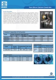
Product Description<br />
<strong>Calcium</strong> Silicide cored <strong>wire</strong> is souce of <strong>Calcium</strong> for steel industries, which is<br />
used for Deoxidation, Desulphurization and Inclusion modification. <strong>Cored</strong> <strong>wire</strong><br />
is prepared by, high grade of CaSi granules or powder, which is filled in U<br />
shaped steel sheath (Made of high quality of cold rolled steel strip), and this U<br />
shapes steel sheath is closed tightly, so called overlapping craft, with help of<br />
equipment. The encapsulated <strong>Calcium</strong> Silicide in steel sheath (called cored<br />
<strong>wire</strong>) is injected into the steel melt with help of <strong>wire</strong> injection system with the<br />
purpose of high recovery of Ca in steel than the virgin Ca / CaSi lumps<br />
addition into the ladle. The powder specification of <strong>Calcium</strong> siliside, which is<br />
used in cored <strong>wire</strong>, strip specification, & <strong>wire</strong> characteristics, is given below:<br />
Chemical Composition of CaSi powder<br />
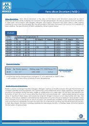
<strong>Ferro</strong> <strong>Silicon</strong> <strong>Calcium</strong> <strong>Cored</strong> <strong>wire</strong><br />
Grade Powder Chemical Composition (%)<br />
Ca Si Al (Max) C (Max) S (Max) P (Max) Fe (Min)<br />
FeSiCa30 28-31 55-65 1.5 1 0.05 0.06 4.5<br />
FeSiCa30+ 30-33 55-65 1.5 1 0.05 0.06 4.5<br />
FeSiCa33 32-34 55-65 1.5 1 0.05 0.06 4.5<br />
Powder Specification<br />
Grade Density<br />
(gm/cc)<br />
Melting Point<br />
(°C)<br />
Size (mm)<br />
FeSiCa30-33 2.5-2.7 1030 – 1200 -1.4 + 0.045<br />
Wire Characteristics<br />
Grade Diameter (mm Shape Powder Fill (gms/mt)<br />
FeSiCa<br />
9±0.5 Round<br />
105±10<br />
13±0.2 Round<br />
230±10<br />
16+0.2 Round<br />
390±10<br />
Strip Specification<br />
Grade Diameter ( Thickness (mm)<br />
mm<br />
EDD IS –<br />
513<br />
9 ± 0.5<br />
13 ± 0.2<br />
0.30 – 0.35 ± 0.03<br />
0.30 – 0.35 ± 0.03<br />
16 ± 0.2 0.35 – 0.4 ± 0.03<br />
Pouring Reliability Into Your Melt - Alloying Solution in Foundry Industry
Coil Specification (Flipping Coil – Horizontal & Vertical)<br />
Details<br />
Powder<br />
Weight<br />
(MT)<br />
Strip<br />
Weight<br />
(MT)<br />
Net<br />
Weight<br />
(MT)<br />
Length<br />
(mtrs)<br />
Internal<br />
Diameter<br />
(mm)<br />
External<br />
Diameter<br />
(mm)<br />
Height<br />
(mm)<br />
9 mm 13 mm 16 mm <br />
F1-05 F1-10 F2-05 F2-10 F2-15 F2-20 F2-05<br />
0.500 1.000 0.500 1.000 1.500 2.000 1.000<br />
0.490 0.980 0.315 0.630 0.945 1.260 0.710<br />
0.990 1.980 0.815 1.630 2.445 3.260 1.710<br />
4760 9520 2172 4337 6521 8695 2631<br />
650 650 650 650 650 650 650<br />
1070 1190 1100 1200 1370 1420 1230<br />
630 900 630 900 900 1000 900<br />
Packing<br />
Packing in flipping cage and mounted on<br />
wooden / mild steel pallet and strapped with<br />
pallet horizontally or vertically. All coils are<br />
wrapped in stretch film & palletized<br />
Application & Addition<br />
<strong>Ferro</strong> <strong>Silicon</strong> <strong>Calcium</strong> <strong>Cored</strong> <strong>wire</strong><br />
Coil Identification<br />
All coils are colour coded and fixed with a detailed<br />
sticker clearly displaying details such as coil no.,<br />
powder content, strip weight, gross weight density &<br />
length. A fluorescent sticker displays the name of the<br />
product in bold letters on the outer diameter of the<br />
coil.<br />
Handling<br />
No metal sling, chain or rod is to be used across the<br />
ID of the coil for handling as it may damage the coil.<br />
Use only polyester, synthetic slings, fork lift/tractor<br />
to handle the coil. The pallet is an integral part of the<br />
coil and it is to be removed till the coil is consumed.<br />
Shelf Life<br />
Follow the shelf life period specified by MINEX<br />
Storage & Safety<br />
To be stored in dry & covered area away<br />
from heat and moisture. Material Safety Data<br />
Sheet can be supplied on demand<br />
CaSi is universal deoxidizing, desulphurising and Inclusion<br />
modifying agent used for manufacture every kind of steel as killed<br />
plain carbon steel, low alloy steel, high grade alloyed steel,<br />
stainless steel etc. (except low Si steel, where CaFe & CaFeAl<br />
<strong>Cored</strong> <strong>wire</strong> is used to get same effect). In combination with<br />
aluminium (FeAl / Al <strong>wire</strong>), it is used in cases where high demands<br />
are made on the degree of purity and the surface quality of steel.<br />
The addition of <strong>Calcium</strong>, and close control over the degree of<br />
addition, is an important step in the steelmaking process. There<br />
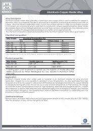
are various way to add calcium into steel melt. Usually calcium<br />
silicide lumps added into bottom of the ladle and steel melt<br />
(temperature 1500 - 1600°C) is poured into the ladle or <strong>Calcium</strong><br />
silicide powder can be added by powder injection method<br />
through lance as shown in figure 1. :-<br />
But it’s very costly and outdated process.<br />
In ladle addition of <strong>Calcium</strong> silicide lumps, the recovery of Ca is very low. Due to lower density (2.5gm/cc) of<br />
CaSi lumps its floats at the surface of melt and losses in oxidation and slag. Usually the recovery of Ca is only less<br />
than 10%.<br />
Whereas in cored <strong>wire</strong> Injection system the recovery of calcium is 15 – 30% with precise control of composition.<br />
In CaSi cored <strong>wire</strong>, CaSi is encapsulated in steel sheath, when injected into steel it can go in depth of steel melt<br />
as shown in<br />
Pouring Reliability Into Your Melt - Alloying Solution in Foundry Industry
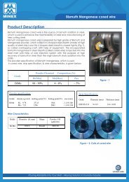
In ladle addition of <strong>Calcium</strong> silicide lumps, the recovery of<br />
Ca is very low. Due to lower density (2.5gm/cc) of CaSi<br />
lumps its floats at the surface of melt and losses in<br />
oxidation and slag. Usually the recovery of Ca is only less<br />
than 10%.<br />
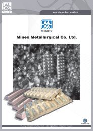
Whereas in cored <strong>wire</strong> Injection system the recovery of<br />
calcium is 15 – 30% with precise control of composition. In<br />
CaSi cored <strong>wire</strong>, CaSi is encapsulated in steel sheath,<br />
when injected into steel it can go in depth of steel melt as<br />
shown in<br />
figure2, where due to sufficient ferrostatic pressure,<br />
calcium bubbles slowly raise to surface and react<br />
efficiently in steel melt and also control of <strong>wire</strong> feeding<br />
with help of <strong>wire</strong> feeder at desired speed ensures high<br />
recovery, precise composition control and less fumes<br />
generation. Thus the cored <strong>wire</strong> injection into the steel is<br />
environmental friendly due to less fumes generation and<br />
economical due to high recovery and less heat rejection.<br />
Recovery of Ca in steel melt depends on various factors as<br />
oxygen content & sulphur content into the melt,<br />
temperature, <strong>wire</strong> injection speed etc...<br />
Effects and Advantages<br />
The following advantages have been reported from Ca – treatment as:<br />
<strong>Ferro</strong> <strong>Silicon</strong> <strong>Calcium</strong> <strong>Cored</strong> <strong>wire</strong><br />
1. To improve steel castability in continuous casting (i.e., minimise nozzle blockage during casting with<br />
consequential reduction in casting speed and possibly the formation of large aggregated alumina<br />
clusters in the solidified product).<br />
2. To get good surface quality and good internal slag cleanliness;;<br />
3. To improve mechanical properties especially in transversal and through<br />
thickness direction, by modifying manganese sulphides to globular Ca-Mn<br />
sulphides, which are nearly non-deformable during rolling.<br />
4. To improve steel machinability at high cutting speeds by forming a protective film on the tool surface that<br />
prolongs the life of the carbide tool;;<br />
5. To minimise the susceptibility of steel to reheat cracking, as in the heat-affected<br />
zones (HAZ) of welds.<br />
6. To prevent lamellar tearing in large restrained welded structures;; and<br />
7. To minimise the susceptibility of high-strength low-alloy (HSLA) linepipe steels to hydrogen-induced cracking<br />
(HIC) in sour gas or sour oil environment.<br />
Fig. 2<br />
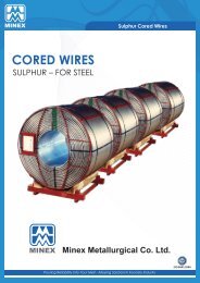
<strong>Calcium</strong> % Yield Comparison Lumps vs <strong>Cored</strong> Wire<br />
Ca Yield<br />
(from CaSi<br />
lumps)<br />
0 5 10 15 20 25 30 35 40 45<br />
Pouring Reliability Into Your Melt - Alloying Solution in Foundry Industry<br />
Ca Yield<br />
(from <strong>Cored</strong><br />
Wire)<br />
The addition rate of the Ca depends on the oxygen &<br />
% <strong>Calcium</strong> Yield<br />
sulphur concentration in steel and desired residual Ca<br />
content in steel. The residual Ca content in steel should be<br />
below the 20 ppm in order gets desired effect as Inclusion modification, improved castebility, reduced nozzle<br />
clogging etc. And also, the addition of calcium to the steel in an amount ensuring that Ca/Al > 0.14 and Ca/S<br />
> 0.7 leads to considerable decrease of the number and area fraction of long inclusions as well as their high<br />
plastic deformability.
<strong>Ferro</strong> <strong>Silicon</strong> <strong>Calcium</strong> <strong>Cored</strong> <strong>wire</strong><br />
The following advantages have been reported from Ca – treatment as:<br />
1. To improve steel castability in continuous casting (i.e., minimise nozzle blockage during casting with<br />
consequential reduction in casting speed and possibly the formation of large aggregated alumina<br />
clusters in the solidified product).<br />
2. To get good surface quality and good internal slag cleanliness;;<br />
3. To improve mechanical properties especially in transversal and through<br />
thickness direction, by modifying manganese sulphides to globular Ca-Mn<br />
sulphides, which are nearly non-deformable during rolling.<br />
4. To improve steel machinability at high cutting speeds by forming a protective film on the tool surface that<br />
prolongs the life of the carbide tool;;<br />
5. To minimise the susceptibility of steel to reheat cracking, as in the heat-affected<br />
zones (HAZ) of welds.<br />
6. To prevent lamellar tearing in large restrained welded structures;; and<br />
7. To minimise the susceptibility of high-strength low-alloy (HSLA) linepipe steels to hydrogen-induced cracking<br />
(HIC) in sour gas or sour oil environment.<br />
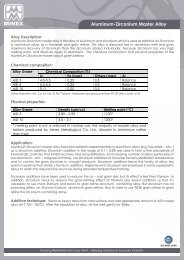
Figure - 3<br />
Fig. 4 The sulpho-oxide inclusion;<br />
1 – calcium aluminate,<br />
2 – sulphide (Ca,Mn)S<br />
As During solidication sulphur is selectively deposed at<br />
grain boundaries in forms of various sulphides and their<br />
solution (especially type II & III) and causes heterogeneity<br />
of mechanical properties of nal products. <strong>Calcium</strong> change<br />
the sulphur release mechanism in such a way that the<br />
sulphur is bound to oxide or aluminate particles and not<br />
deposed as sulphide inclusions at grain boundaries during<br />
the steel solidication. see microstructure - Alumina inclusions<br />
form calcium aluminates that can be as cores for<br />
precipitating “oxysulphide” inclusions (Figure 4). The outer<br />
layer contains calcium sulphide (or calcium sulphide with<br />
little manganese) when sulphur content is low or calciummanganese<br />
sulphide when sulphur content is higher. The<br />
mechanism and stage of formation of the oxysulphides is<br />
not fully known,<br />
but the favourable inuence of these complex inclusions<br />
for many products is well known i.e. improving the machinability<br />
of hardening and tempering as well as casehardening<br />
steels. The formation of oxide layer on the tool is optimized<br />
and results in longer tool life and in possibility to use<br />
higher cutting speeds. Better surface quality of the product<br />
is also attained. In addition, good castability is an important application of Ca-treatment.<br />
For some products, however, the Ca-treatment and hence modication of inclusions must be avoided. For<br />
instance, well deformable silicate type inclusions are desirable for <strong>wire</strong> materials and undeformable inclusions<br />
should be avoided. In general, the properties of nal products must be thoroughly considered when<br />
choosing the proper ladle treatment.<br />
Pouring Reliability Into Your Melt - Alloying Solution in Foundry Industry