RNAS Howden - The Airfield Research Group
RNAS Howden - The Airfield Research Group
RNAS Howden - The Airfield Research Group

Create successful ePaper yourself
Turn your PDF publications into a flip-book with our unique Google optimized e-Paper software.
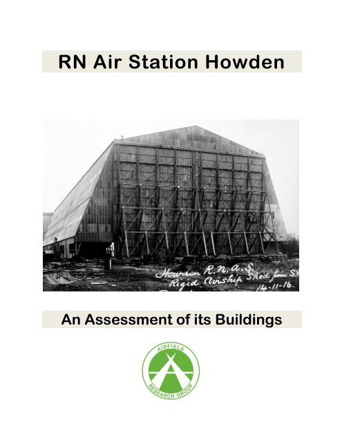
RN Air Station <strong>Howden</strong><br />
An Assessment of its Buildings
Contents<br />
Part 1: Methodology & Notes on Sources 1<br />
Part 2: Royal Naval Air Service – An Overview 2<br />
Part 3: Location and Planning 5<br />
Part 4: <strong>The</strong> Airship Sheds 9<br />
Part 5: Other Buildings 20<br />
Part 6: Operational History 26<br />
Plate 1: MT Garage 13-09-17 1<br />
Plate 2: <strong>Howden</strong> Site Plan 1918 4<br />
Plate 3: Map showing building numbers (un-official) 6<br />
Plate 4: Brindcommon Farm 23-03-17 7<br />
Plate 5: Wireless station looking south 09-08-17 8<br />
Plate 6: Pigeon Loft 17-04-17 8<br />
Plate 7: Coastal shed and windbreak under construction 27-07-16 9<br />
Plate 8: Coastal shed with wind break under construction. 10<br />
Plate 9: Coastal shed with wind break and petrol installation 10<br />
Plate 10: Half cross-section of Rigid Shed 11<br />
Plate 11: Rigid Shed No.1 29-09-16 12<br />
Plate 12: Rigid Shed No.1 12<br />
Plate 13: Aerial view showing the twin shed foundation blocks being constructed 14<br />
Plate 14: Travelling stage being erected 11-12-17 15<br />
Plate 15: View from SW showing the right-hand shed annexe 16<br />
Plate 16: Twin Shed under construction 14-05-18 17<br />
Plate 17: Twin shed with door framework 04-03-19 18<br />
Plate 18: Twin shed 04-03-19 18<br />
Plate 19: Twin shed 04-03-19 19<br />
Plate 20: Twin shed c.1920 19<br />
Plate 21: Servant’s quarters 20<br />
Plate 22: Men’s quarters 21<br />
Plate 23: Officers’ quarters 21<br />
Plate 24: Post office, church and YMCA 22<br />
Plate 25: Gasholder 23-07-18 23<br />
Plate 26: Gasholder (full) 23-05-17 23<br />
Plate 27: Power station 27-07-16 24<br />
Plate 28: Magazine 24<br />
Plate 29: Hydrogen gas water plant 25<br />
Plate 30: Hydrogen gas plant and cooling tower 15-5-18 25<br />
Plate 31: Water tower c.1918 32<br />
Plate 32: Water tower c.1981 33<br />
Plate 33: Steel tie ring – <strong>Howden</strong> 33
Part 1: Methodology & Notes on Sources<br />
This desk-based study has been commissioned by CGMS to provide baseline information in order to<br />
compile a record of the buildings and structures that were once part of the First World War <strong>Howden</strong><br />
Airship Station.<br />
<strong>The</strong> report has taken the central part of the 1916 requisitioned land for its main study area; it includes the<br />
aerodrome and an 80 acre plot which was once occupied by the station buildings but which has since<br />
been demolished. <strong>The</strong> area that has been studied is largely covered by the Ordnance Survey grid<br />
kilometre square SE 74 32. This report is largely based on primary sources located at <strong>The</strong> National<br />
Archives (TNA), Kew, and includes a large and very important collection of contemporary photographs<br />
showing the construction of the station between 1916 and 1919. <strong>The</strong> presence of such a large collection<br />
of images from WWI showing a military air station being built is quite remarkable. Although the originals<br />
are generally quite poor in quality, as a result of bad storage (many have deteriorated over time), they<br />
have been copied and then enhanced digitally. <strong>The</strong> results are a considerable improvement on the<br />
originals and these have been transferred to a CD in support of this report.<br />
Another photographic source is the <strong>Airfield</strong> <strong>Research</strong> <strong>Group</strong> archives which include images taken in the<br />
early 1980s, plus a few more recent ones – these have also been added to the CD.<br />
A search was made of surviving Air Ministry records at the TNA. Relevant files at the TNA mainly consist<br />
of documents relating to the post-WWI period, with the majority of files concerned with the problems<br />
associated with the twin shed and the construction of the R100.<br />
A key source is the HMSO publication CB 819: Royal Naval Air Service State of Development of the<br />
Airship Service, of 1 January 1918. This booklet gives an excellent description of the operational side of<br />
all airship patrol stations.<br />
Paul Francis, AIFA. Trading as ARP<br />
9 Milton Road, Ware,<br />
Herts SG12 0QA<br />
Tel: 01920 420452<br />
E-Mail: paul.francis30@ntlworld.com<br />
Plate 1: MT Garage 13-09-17<br />
1
Part 2: Royal Naval Air Service – An Overview<br />
In October 1912, the Admiralty decided to establish a chain of seaplane and airship stations on the eastcoast<br />
of Britain. <strong>The</strong> earliest of these, after Eastchurch, was the seaplane station on the Isle of Grain,<br />
commissioned in December 1912, with Lieutenant JW Seddon as officer in command. <strong>The</strong> was followed,<br />
in the first half of 1913, by seaplane stations at Calshot, Cromarty, Felixstowe and Yarmouth. HMS<br />
Hermes replaced HMS Actaeon on 7 May 1913, as headquarters of the Naval Wing and her<br />
commanding officer was Captain GW Vivian, RN – who was also given charge of all coastal air stations.<br />
An airship station was established at Kingsnorth, completed in April 1914, by which time all airships had<br />
been handed over to the Admiralty.<br />
In the naval manoeuvres of July 1913, the Hermes was equipped with launching platforms plus two<br />
seaplanes and operated with the fleet. On 26 October 1913, the First Lord of the Admiralty (Winston<br />
Churchill), outlined his future policy for the Royal Naval Air Service (<strong>RNAS</strong>). He recommended three new<br />
types of aircraft: an overseas fighting seaplane, to operate from a ship, a scouting seaplane to work with<br />
the fleet at sea, and a home-defence fighting aeroplane, to repel enemy aircraft and to carry out patrol<br />
duties along the British coast.<br />
<strong>The</strong> Admiralty conducted many experiments in using the aircraft as a fighting machine, including bombdropping<br />
trials using a Shorts pusher type carrying a dummy 100lb bomb, and in December 1912,<br />
experiments were conducted to determine the lowest height at which bombs could be released from an<br />
aeroplane. Other work included the firing of Hales grenades from rifles, and trials were carried out during<br />
October 1913 using guns and special types of ammunition against balloon fabric at the Cotton Powder<br />
Company’s works at Faversham. At the outbreak of war, the only effective weapon against the Zeppelin<br />
from the air was the Hales grenade, and these were hastily distributed among the East Coast seaplane<br />
stations. <strong>The</strong> Naval Wing had also conducted experiments with the mounting of machine-guns to aircraft<br />
before the outbreak of WWI. <strong>The</strong> <strong>RNAS</strong> therefore, was more experienced in using aircraft as a fighting<br />
machine than the RFC, and accordingly, became responsible for the defence of Britain while the RFC,<br />
had the task of scouting for the British Expeditionary Force (BEF).<br />
At the end of 1913, HMS Hermes was paid off, and the headquarters of the Naval Wing transferred to<br />
the Central Air Office, Sheerness with Captain Scarlett, RN (2 nd in command on Hermes), placed in<br />
charge with the title of Inspecting Captain of Aircraft. At the request of the Secretary of War (Lord<br />
Kitchener), the First Lord of the Admiralty was invited in September 1914, to become responsible for<br />
home defence against enemy aircraft.<br />
At the beginning of the war, the <strong>RNAS</strong> had only two aircraft fitted with machine-guns, and one airship<br />
(No. 3 Airship, the Astra-Torres), fitted with a Hotchkiss gun. All other aircraft were equipped with rifles.<br />
<strong>The</strong> Isle of Grain had four Hales grenades and both Hendon (the station for the defence of London) and<br />
Felixstowe had twelve each. In contrast, Eastchurch had a 150 hand-grenades, 42 rifle grenades, 26<br />
bombs (twenty pound), and a Maxim gun.<br />
On 1 July 1914, the separate existence of the <strong>RNAS</strong> (with its own constitution) was officially recognised,<br />
with administration coming under the Air Department of the Admiralty and the Central Air Office. <strong>The</strong> first<br />
real opportunity to demonstrate its use in connection with naval operations, came during the review of<br />
the fleet by the King, at Spithead, from 18 to 22 July 1914. On 20 July an organised flight of seventeen<br />
seaplanes, and two flights of aeroplanes in formation headed by Commander Samson, flew over the<br />
fleet. Three airships from Farnborough and Kingsnorth also took part.<br />
On 29 July, instructions were issued, that the duties of scouting and patrol were to be secondary to the<br />
protection of the country against hostile aircraft – all aeroplanes were to be kept at readiness. It was not<br />
until 21 December 1914, that the first air-raid took place on Britain, when a single aircraft dropped bombs<br />
close to the Admiralty Pier at Dover, and on the night of 19 / 20 January, the first airship raid on Britain<br />
took place. On 24 August 1914, the Government approved the formation of two <strong>RNAS</strong> squadrons, one to<br />
be based at Fort Grange.<br />
2
On the outbreak of war, the role of the <strong>RNAS</strong> was to support the BEF during its passage across the<br />
Channel, and regular patrols were flown between Westgate and Ostend. <strong>The</strong> earliest measure of<br />
defence for the UK, ordered by the Admiralty, was the institution of a coastal patrol of the East Coast,<br />
from Kinnaird’s Head in Aberdeenshire, to Dungeness in Kent. Incomplete RFC squadrons undertook the<br />
northern and southern extremes, while the <strong>RNAS</strong> patrolled the most vulnerable part. This arrangement<br />
was altered slightly after the Germans had established themselves in Belgium, as it was believed that<br />
they would use Belgium to attack the vulnerable points along the Thames Estuary. For home defence the<br />
<strong>RNAS</strong> was therefore, concentrated in a line between the Humber and the Thames. For anti-submarine<br />
patrol duties, there were three main types of operational <strong>RNAS</strong> stations:<br />
• Marine Operations (Aeroplane) Station – aerodrome for landplanes<br />
• Marine Operations (Seaplane) Station – seaplane station for seaplanes<br />
• Marine Operations (Balloon) Stations – aerodrome for balloons used in conjunction with Naval<br />
craft on convoy or patrol duties<br />
• Airship Patrol Station – either dedicated to rigid or non-rigid airships.<br />
In May 1915, the first <strong>RNAS</strong> kite balloon sections were despatched to France. During January 1915,<br />
Wing Commander Maitland, <strong>RNAS</strong>, had inspected a Belgian kite balloon (probably of the French Caquot<br />
type after the inventor Albert Cacquot [1881-1976]), which had been flying at a time when British<br />
balloons were grounded due to the poor weather. He therefore came to the conclusion that captive<br />
spherical balloons were handicapped by the weather and recommended the formation of kite balloon<br />
sections using sausage-like streamlined captive balloons. <strong>The</strong> first British wartime dirigible became<br />
known as the SS type or, Submarine Scout. This particular balloon consisted of a modified BE2c<br />
fuselage fitted with a 70hp Renault engine suspended beneath a simple envelope of rubberised fabric.<br />
<strong>The</strong>y were designed for searching narrow channels such as the Dover Straits or Irish Narrows.<br />
On 1 August 1915 the Admiralty Air Department reorganised the <strong>RNAS</strong>. <strong>The</strong> air stations were now<br />
grouped together for operations under the senior naval officer of the nearest naval base – for example,<br />
the Marine Operations (Aeroplane) Station at Sea Houses, Northumberland came under the senior Naval<br />
Officer, Tyne for operations.<br />
This had the immediate effect of having a closer liaison between air and surface craft. Admiral Bacon, for<br />
example, became responsible for the aeroplane and seaplane bases at Dover and Dunkirk, together with<br />
the Submarine Scout (SS) airship stations at Capel and Polegate. To advise him on air matters, Wing<br />
Commander CL Lambe was appointed to the Admiral’s staff.<br />
An airship patrol of the Channel was established from 10 August 1915 and undertaken by airships Nos. 3<br />
and 4 – a typical patrol lasted twelve hours, while an average time for a seaplane was just three hours.<br />
<strong>The</strong> assembly and testing of a new and larger type of non-rigid airship began in September 1915, known<br />
as the Coastal Class. This was essentially an Astra-Torres envelope with a car made from two Avro<br />
fuselages joined together with their tails removed. <strong>The</strong>y could cruise at 45 mph and had an eleven hour<br />
endurance. In January 1916, the first Coastal Class airship station was commissioned at Pembroke,<br />
manned by personnel from the airship station at Marquise. On 15 March <strong>Howden</strong> and Longside opened<br />
and also in March, the first airship shed at Cranwell had been completed. Eventually all free balloons<br />
were transferred from Wormwood Scrubs when Cranwell took over the training of airship officers and<br />
men from Kingsnorth.<br />
<strong>The</strong> first coastal-type ship for <strong>Howden</strong> was delayed until 26 June 1916 – Coastal C11 being the first<br />
airship to arrive at <strong>Howden</strong> (from Kingsnorth) on 26 June 1916.<br />
3
Plate 2: <strong>Howden</strong> Site Plan 1918<br />
4
Part 3: Location and Planning<br />
<strong>Howden</strong>, in East Yorkshire functioned as an <strong>RNAS</strong> operational patrol station for non-rigid and rigid<br />
airships 1 . It was also a parent to two sub-stations or mooring stations, located at Lowthorpe and<br />
Kirkleatham.<br />
<strong>The</strong> parent site is located to the north of <strong>Howden</strong> village mainly on the east side of Bubwith Road, but<br />
the requisitioned land appears to have included as far west as Brindley’s Plantation, and as far south to<br />
include part of Spaldington Common, then Hall Farm in the east and Mount Pleasant Farm to the north.<br />
Brindcommon Farm, located in the southern corner of the site, was at first used by the works department<br />
but was then demolished.<br />
<strong>The</strong> site was planned from the beginning, based around a standard <strong>RNAS</strong> patrol station arrangement<br />
with the main sheds being built in two phases. Firstly around October 1915, two coastal class sheds<br />
were erected by the Cleveland Bridge and Engineering Co. of Darlington. This was followed by a larger<br />
rigid class shed by Frindlay and Co Ltd of Motherwell, being completed in December 1916.<br />
<strong>The</strong> usual design practice for airship stations was enforced by aligning the sheds with their length in the<br />
direction of the prevailing wind, so that the majority of wind normally encountered was more or less up<br />
and down the shed – a dead cross-wind was only encountered on rare occasions.<br />
In addition to the patrol station arrangement, another much larger twin shed was also constructed by<br />
Cleveland Bridge and Engineering Co Ltd. <strong>The</strong> erection of this building commenced in August 1917 and<br />
was completed around 31 March 1919.<br />
<strong>The</strong> planning of the original station consisted of the two coastal sheds positioned in front of the first rigid<br />
shed on the NE end so that they could act as wind breaks, and projecting out from either coastal shed<br />
was a 700 feet long wind shield or break constructed of steel framing. This arrangement offered<br />
protection to the ship as it left or entered its shed during a cross-wind.<br />
<strong>The</strong> other buildings were standard single-storey designs, similar to others erected at various airship<br />
patrol stations in the UK, such as East Fortune and Moreton. Buildings were generally arranged within<br />
three main groups, beginning with a domestic series of structures to the south-west.<br />
<strong>The</strong> main 18 feet wide <strong>RNAS</strong> service road (aligned SW / NE) was constructed off the <strong>Howden</strong>–Bubwith<br />
road, and buildings were erected to the north of it while the airship sheds were to the south (a section<br />
was lit by electric lighting, the fittings fixed to lamp standards). Buildings or groups of structures were<br />
served by a nine feet wide road network with passing places, off the main one. <strong>The</strong> site was also served<br />
by a siding off the North Eastern Railway line from Selby to Hull which left the main line at North<br />
<strong>Howden</strong> Junction and ran north-west to enter the site north of <strong>Howden</strong> Station – a distance of 1.5<br />
miles. This crossed the Bubwith Road at the Spaldington road junction; the line crossed the<br />
aerodrome towards the technical buildings and airship sheds. About mid-way across there were three<br />
reception sidings (the largest for twelve wagons) with spurs to the two rigid sheds and the main one<br />
terminated at the coal store.<br />
<strong>The</strong> aerodrome had maximum dimensions of 3,100 by 2,600 yards and the whole site covered an area of<br />
1,240 acres of which 80 acres was occupied by station buildings. <strong>The</strong> aerodrome occupied the land to<br />
the south, east and west of the airship sheds, some existing drains and ditches were piped and filled in<br />
and a cinder nine feet wide perimeter track was built from the eastern end of the <strong>RNAS</strong> road in the north.<br />
Its route went south to connect with the Spaldington Road. Ten mooring block sites were built around<br />
this perimeter, of which one was located on the south side of Spaldington Road, and another to the east<br />
of the <strong>Howden</strong>–Bubwith Road.<br />
1 <strong>The</strong> term ‘rigid’ is applied to those airships which have a hull framework of built-up timber or aluminium alloy, covered with a flexible envelope. Nonrigid<br />
types have no such hull framework, and retain their shape only as long as the pressure within the flexible envelope is maintained greater than<br />
ambient atmospheric pressure.<br />
5
On the southern side of Spaldington Road, just east of Spaldington Grange, was the site of the wireless<br />
station.<br />
<strong>The</strong> station complement at the beginning of 1918 was 40 officers and 612 men and for operational<br />
purposes the station was located in North East Area; No.18 (Operations) <strong>Group</strong>.<br />
Plate 3: Map showing building numbers (un-official)<br />
6
Key to Plate 3<br />
1 Airship Shed 320 ft by 110 ft by 80 ft 2 Windbreak<br />
3 Windbreak 200 ft by 50 ft 4 Airship Shed 700 ft by 150 ft by 100 ft<br />
5 Windbreak 700 ft by 70 ft 6 Twin Airship Shed<br />
7 Railway Siding 8 Compressor House (drainage)<br />
9 Officers’ Quarters 10 MT Garage<br />
11 Servants’ Quarters 12 Warrant Officers’ Quarters<br />
13 Station Offices 14 First Aid Room<br />
15 Detonator Store 16 Small Arms Ammunition Store<br />
17 Latrine Block 18 Men’s Barracks<br />
19 CPO & PO’s Quarters 20 CPO & PO’s Mess<br />
21 Men’s Mess 22 Unknown<br />
23 Works Dept Office 24 Cookhouse<br />
25 Church & Post Office 26 YMCA Hut<br />
27 Smith’s Shop 28 Petrol Installation<br />
29 Lecture Room 30 Water Tower<br />
31 Latrine Block 32 Compressor House<br />
33 Water Gas Hydrogen Plant 34 Gas Holders 250,000 cu ft<br />
35 Gas Holders 500,000 cu ft 36 Water Gas Hydrogen Plant<br />
37 Water Gas Hydrogen Plant 38 Gas Bottle Storage Foundation Blocks<br />
39 Compressor House 40 Silicol Plant & gasholder 20,000 cu ft<br />
41 Unknown 42 Electric Light & Power Station<br />
43<br />
DW Compound & Stores (carpenters,<br />
general store, cement store & latrines)<br />
44 Magazine<br />
45 Temporary Silicol Plant 46 Telephone Exchange<br />
47 Pigeon Loft 48 Meteorological Office<br />
49 Station Store 50 Old Wireless Station<br />
Plate 4: Brindcommon Farm 23-03-17<br />
7
Plate 5: Wireless station looking south 09-08-17<br />
Plate 6: Pigeon Loft 17-04-17<br />
8
4.1 Coastal Sheds<br />
Part 4: <strong>The</strong> Airship Sheds<br />
<strong>The</strong> two coastal sheds were constructed by the Cleveland Bridge & Engineering Co Ltd, beginning<br />
around September 1915, and preceded the rigid airship shed. <strong>The</strong>y were 11 bays long with full length<br />
annexes (22 feet wide) along both longitudinal walls. <strong>The</strong> main doors, in two leaves, were located at<br />
either end. <strong>The</strong> sheds were separated by a distance of 520 feet, and No.1 rigid airship shed was erected<br />
in a central position to the south-west of them with its north-east doors aligned with the south-west ends<br />
of the coastal sheds. <strong>The</strong> gaps between the rigid and the coastal sheds were occupied by 80 feet high<br />
screens. <strong>The</strong> windscreen of the north coastal shed was extended and as an experiment it was covered<br />
with expanded metal instead of corrugated iron. <strong>The</strong> tests carried out proved satisfactory as no suction<br />
was caused and eddies were reduced. In addition the bottoms of all windscreens were filled in with<br />
brushwood which also gave good results. <strong>The</strong> main screens were 380 feet long by 70 feet wide on the<br />
north-east side and 200 feet by 50 feet on the south-west side.<br />
• Coastal airship shed No.1 was 323 ft 1 in long by 110 ft 8 in wide and a clear height of 80 ft 2 in.<br />
• Coastal airship shed No.2 was 320 ft long by 110 ft and a clear height of 80 ft.<br />
Note: another source gives both sheds at 320 ft by 110 ft by 80 ft<br />
Plate 7: Coastal shed and windbreak under construction 27-07-16<br />
9
Plate 8: Coastal shed with wind break under construction.<br />
Plate 9: Coastal shed with wind break and petrol installation<br />
under construction 25-05-17<br />
10
4.2 Shed No.1<br />
A Findlay & Co. Ltd was awarded a contract in 1916 to design and build the No.1 shed at <strong>Howden</strong>. <strong>The</strong><br />
two sheds to house non-rigid coastal class airships had already been completed when construction<br />
started. <strong>The</strong> new shed had a 150ft clear span, 100ft clear height and a length of 700ft. Roof girders were<br />
spaced at 25ft centres which were carried on 98ft high braced ‘A’-frame trestles forming 28-bays. For<br />
stability wall trestles were joined by six longitudinal girders. Internal annexes were accommodated within<br />
the ‘A’-frame trestles, these being 35ft wide and ran the whole length of the shed. <strong>Howden</strong> No.1 was<br />
completed in December 1916. <strong>The</strong> shed had been erected by two steam derrick cranes placed on<br />
staging made out of the permanent doors, and the roof girders were then lifted in one piece.<br />
It was constructed for a new class of rigid airship known as Class 23.<br />
Plate 10: Half cross-section of Rigid Shed<br />
11
Plate 11: Rigid Shed No.1 29-09-16<br />
Plate 12: Rigid Shed No.1<br />
12
4.3 Shed No.2<br />
4.3.1 Description<br />
<strong>The</strong> twin shed at <strong>Howden</strong> (No.2 shed), was erected between November 1917 and 1 April 1919 to house<br />
two of the latest type of rigid airships. Designed and constructed by Sir William Arrol & Co. Ltd – not only<br />
was it the largest airship shed ever built in Britain, covering 8.5 acres (including doors) – it was also the<br />
largest building in the UK. Two spans were erected, each of 150 feet by 130 feet high and a length of<br />
750 feet – the total weight being 5,208 tons. It was constructed mainly of steel with some parts in timber<br />
and brick.<br />
<strong>The</strong>re were therefore two spans arranged side-by-side (coupled or twin shed), supported on the inside<br />
by a shared row of central columns and on the opposite ends by frames running down both sides. <strong>The</strong><br />
outer frames also formed full-length annexe workshops, each 35 feet wide. <strong>The</strong> clear height at the centre<br />
of the main spans was 140 feet and to the ridge of the roof, a total of about 160 feet. Sliding doors were<br />
provided at both ends, consisting of four leaves, each 150 feet by 130 feet. <strong>The</strong>se were independent of<br />
the shed and were of the semi-ballasted type, running on parallel tracks which were 48 feet apart.<br />
<strong>The</strong> main spans of the shed were three-pin arches, the springing pin on the outer side (3 inches in<br />
diameter), rested at a height of 60 feet from the floor (at the highest point of the annexe roof), and this<br />
was fixed to a lattice framework which formed the inner part of the annexe. <strong>The</strong> main ribs were spaced at<br />
30 feet centres arranged as 25 bays and these carried side and roof girders.<br />
<strong>The</strong> annexe framework was also of rigid construction, there was a concrete ceiling at 17 feet height and<br />
this ground floor section was separated from the main shed by brickwork; the outer walls were also brick.<br />
One annexe had internal brick walls which provided stores, workshops and offices, but the other annexe<br />
may have been left undivided. Annexe foundations were reinforced concrete blocks with four 1.625 inch<br />
anchor bolts set at an angle of 45 degrees to resist uplift under wind pressure.<br />
<strong>The</strong> centre columns above annexe height were 12 feet wide but these spread out to 30 feet at ground<br />
floor level. <strong>The</strong>y were spaced at 30 feet centres and were rigidly braced by two rows of box girders. <strong>The</strong><br />
foundations were reinforced with both legs being anchored down by with four 1.25 inch bolts.<br />
A concrete floor was provided with a minimum thickness of four inches, it covered the entire area of the<br />
shed including annexes (about 34,300 square yards), which was laid over a bed of hardcore also of four<br />
inches thick. Longitudinal and cross trenches were inserted into the floor as required to carry hydrogen<br />
mains, heating pipes and for drainage etc. Mooring blocks were also provided at intervals in the floor for<br />
anchoring airships, and a railway track of 4 ft 8.5 inch gauge was laid into each half of the shed (see<br />
below).<br />
Ventilation was in the form of a continuous framework which ran full length and consisted of a series of<br />
fixed louvres each side.<br />
<strong>The</strong> sides and roof were clad with 20-gauge corrugated galvanised sheeting. and explosion flaps were<br />
fitted high up on each side; these were hinged at the bottom and loosely held in place at the top and<br />
covered in corrugated sheeting.<br />
Seven emergency panic doors were provided on the ground floor, and runway beams and gangways<br />
were provided at high level.<br />
<strong>The</strong> main roof drained into three pressed-steel gutters and these discharged directly into sixteen storage<br />
tanks, each of 5,300 gallons capacity. <strong>The</strong>se were located close to the eaves and valley gutters. An<br />
observation cabin (10 ft by 6 ft) was erected on the ridge at one end of the shed, with access from the<br />
central gangway below, and an outside fire-escape.<br />
13
<strong>The</strong> site for the twin shed was found to be practically level and consists of roughly 12 inches of soil,<br />
overlying six feet of clay, which is bedded on sand and warp. It was therefore decided to rest the shed on<br />
the crust of clay, and in order to avoid the possibility of penetrating it, the maximum depth of foundations<br />
was fixed at three feet below ground level, the floor level being six inches above the ground line.<br />
<strong>The</strong> wind load on the side of the shed was 30 lb per square foot, which gave a total pressure of roughly<br />
60 tons per panel, or 1,500 tons over the full length of the shed. <strong>The</strong> reaction on the bases were<br />
therefore quite considerable, and as the concrete was limited to just 3 feet 6 inches in thickness, with a<br />
ground pressure of 15 cwt per square foot, it was necessary to reinforce all main blocks. <strong>The</strong> sizes of<br />
these blocks were as follows:<br />
Annexe outer block 9 ft 6 in by 9 ft 6ins by 3 ft 6 in<br />
Annexe column 15 ft 6 in by 13 ft by 3 ft 6 in<br />
Centre columns (each leg) 15 ft by 12 ft 6 in by 3 ft 6 in<br />
Plate 13: Aerial view showing the twin shed foundation blocks being constructed<br />
August 1917<br />
14
4.3.2 Staging<br />
For the erection of this high structure it was found necessary to provide two temporary steel stages, each<br />
96 feet wide, 106 feet long and 100 feet high, each carrying two 5-ton 110-foot jib steam derrick cranes.<br />
<strong>The</strong>se special stages were used instead of using the main doors as stages as used in the No.1 shed.<br />
<strong>The</strong> stages and cranes allowed perfect command of the erection, with the whole of the shed and main<br />
door steelwork being erected by them. Each one was erected onto steel bogies which travelled on the<br />
two railway tracks. As the erection proceeded the stage was drawn back by means of a locomotive crane<br />
and wire rope tackles. <strong>The</strong> railway tracks had to be kept well ballasted, level and parallel. Near the top<br />
on the outer face of each stage a moveable arm was fitted, for use in securing the first length of main rib<br />
after connection to the bottom pin, and for holding it in position until the top length of the main rib was<br />
erected and connected to the centre.<br />
A platform 25 feet by 96 feet, constructed of three-inch timbers and carried by steel girders on top of the<br />
staging was built some 26 feet higher than the base of the cranes and some 126 feet from the ground.<br />
This provided a safe working platform for the men erecting the main arch. Electric lights had to be fitted<br />
to the tops of the outer 110-foot jibs for protection against night flying, as the end of the jib was<br />
about 200 feet above ground level.<br />
Plate 14: Travelling stage being erected 11-12-17<br />
15
4.3.3 Shed Erection<br />
Following the construction of the staging, came erecting of the steelwork of the shed, and a start was<br />
made at the west end. <strong>The</strong> north and south annexes frameworks were erected first up to the level of the<br />
first longitudinal box girder, a height of about 60 feet. <strong>The</strong> main columns of the annexes were carefully<br />
plumbed and levelled, and bolted to the rakers and box girder ready for the supporting arch.<br />
After the erection of the annexes and door rails, the east main doors were constructed. <strong>The</strong> two outer<br />
doors were built first and moved out, and then the two inner doors were built immediately afterwards.<br />
<strong>The</strong> two outer cranes were used on the stages for this erection, and the two inner cranes made a start on<br />
raising the centre columns.<br />
<strong>The</strong> door carriages and wheels were first placed in position on the rails and chocked up ready for<br />
receiving the bottom door framework. Once this had been completed the remaining steelwork was<br />
erected, the outer door first, then the inner door.<br />
<strong>The</strong> centre columns in suitable pieces were lifted by the two inner cranes on the stages, and bolted<br />
together up to and including the main box girder at a height of 96 feet. <strong>The</strong>se columns were now ready to<br />
receive the main arch. <strong>The</strong> north and south annexes and centre columns were also ready to receive the<br />
pair of spans of the main arches. <strong>The</strong> bottom pin connection rested on the box girder of the annexe main<br />
column, and the vertical length of the main arch was erected over the first two annexe members from the<br />
east end.<br />
Plate 15: View from SW showing the right-hand shed annexe<br />
Central columns finished up to main box girder height, travelling stage and door framework 23-07-18<br />
Both members were securely fixed temporarily by guys, so that the bracings could be fitted in the first<br />
bay, which were plumbed up and made to receive the remaining members of the main arch, erection<br />
going forward on the north and south arches, and the two spans being raised simultaneously as far as<br />
possible. <strong>The</strong> vertical members of the main arch, which connect to the pins resting on the box girder of<br />
the centre column were then elevated. <strong>The</strong> north and south pieces were temporarily bolted together on<br />
the ground and lifted in one piece, carrying the pins and brackets with them.<br />
16
<strong>The</strong> last two members of the main arch were then lifted, one by each crane, one slightly ahead of the<br />
other; the two were then lowered into position, connected up at the eaves, and the centre pin driven<br />
home. <strong>The</strong> first main arch was thus now completed and the second main arch was then erected and all<br />
wind girders and intermediate trusses, along with braces were inserted to complete the bay.<br />
A fine day was chosen for the elevation of the first bay and the stage was placed in such a position as to<br />
allow both main arch ribs to be raised without moving the stages. <strong>The</strong> stages were then moved<br />
backwards into position for the next bay, this process being repeated as the process proceeded.<br />
After the completion of the last bay the west end main doors were erected in a similar manner to those at<br />
the east end.<br />
4.3.4 Stage Removal<br />
A three-ton hand crane was installed on each stage for taking down the steam derrick cranes, and after<br />
removal of the cranes from the stages, a 110-foot jib crane was erected at ground level on bogies<br />
running on railway track, for the taking down of the staging steelwork.<br />
4.3.5 Sundry Work<br />
On completion of the steelwork, came the sheeting, glazing, painting and sundry work. <strong>The</strong> shed floor<br />
had been covered with hardcore, and this helped in keeping the site dry. <strong>The</strong> concreting of the floor and<br />
the construction of the hydrogen and heating trenches then followed, after the completion of the roof<br />
covering. <strong>The</strong> floor was concreted in-situ, using nine-foot square slabs.<br />
Plate 16: Twin Shed under construction 14-05-18<br />
17
Plate 17: Twin shed with door framework 04-03-19<br />
Plate 18: Twin shed 04-03-19<br />
18
Plate 19: Twin shed 04-03-19<br />
Plate 20: Twin shed c.1920<br />
19
5.1 Domestic <strong>Group</strong><br />
Part 5: Other Buildings<br />
At the south-west end of the <strong>RNAS</strong> road where it joined the public one, the first building to the south of<br />
this road was a telephone exchange and barrack master’s office. On the north side was the pigeon loft<br />
and further north again towards New Plantation was the meteorological office.<br />
Going east along the <strong>RNAS</strong> road, the next building complex was the officers’ quarters – a timberframed<br />
building with its own driveway, (the centre of this structure was located 900 feet from the main<br />
entrance). This was followed by the steel-framed motor transport garage, MT petrol and oil stores, plus<br />
servants and WOs quarters (brick-built) as well as the depot or administration offices and the Air<br />
Inspection Directorate (AID) offices.<br />
<strong>The</strong> next group of structures consisted of the main domestic accommodation and this was located 200<br />
feet north of the <strong>RNAS</strong> road. Adjacent to the <strong>RNAS</strong> road was the works department offices and a small<br />
cook house, and on the north side was a parade ground followed by the main domestic group.<br />
Men’s accommodation consisted of two groups of eight barrack huts (wooden Armstrong huts). <strong>The</strong>se<br />
were separated by a small group of mess buildings which included a central kitchen block flanked on<br />
three sides by mess blocks. <strong>The</strong> CPOs / POs quarters were located to the north of the central mess<br />
complex. Isolated in the extreme north, located between the northern section of Great Committee Drain<br />
and New Plantation was a detonator store and small arms ammunition store.<br />
Further east along the <strong>RNAS</strong> road was the post office, YMCA hut and church. Further east along the<br />
<strong>RNAS</strong> road was the technical area.<br />
Plate 21: Servant’s quarters<br />
20
Plate 22: Men’s quarters<br />
Plate 23: Officers’ quarters<br />
21
5.2 Technical <strong>Group</strong><br />
At the NE end of the main <strong>RNAS</strong> road was the technical group of buildings and structures, these were<br />
all located on the northern side of the <strong>RNAS</strong> road. <strong>The</strong>se were a mixture of brick and steel-framed<br />
structures, principally single-storey but with some at two-storey such as the electric light and power<br />
station.<br />
Between the <strong>RNAS</strong> road and the railway with its small siding, was a lecture room followed by a 20,000<br />
cu feet gasholder, silicol plant and water tower. Compressor plant for filling bottles and gas holders<br />
were three, 600 lbs for filling the holders. One 1,600 lbs and two 1,800 lbs cu feet capacity compressors<br />
were used for filling British Mannesmann Tube Co gas bottles. <strong>The</strong>re were the original two 250,000 cu<br />
feet gas holders plus the later two 500,000 cu feet gas holders. After the gas plant, further east was the<br />
electric light and power station plus a boiler house.<br />
<strong>The</strong> gas plant area was located to the north of the railway and consisted of (when fully developed) a<br />
pair of water-gas iron contact plants which could be worked separately, giving a total capacity of one<br />
million cubic feet per week for each plant unit. <strong>The</strong>re were four small gasholders, a compressor house<br />
for gas filling, four 250,000 cu feet capacity gas holders and two long and parallel foundation blocks for<br />
storing gas cylinders. Construction of the first water-gas plant was completed in May 1917 and the<br />
second was completed in November 1918.<br />
<strong>The</strong> extreme eastern end of the <strong>RNAS</strong> road terminated with a turning circle and it was here where the<br />
Directorate of Works stores and workshops were located it was also the terminus for the railway. This<br />
area included a general store, carpenter’s shop, cement store, a station store, blacksmith’s shop,<br />
destructor, and the original wireless station.<br />
Positioned further east in an isolated position, was the magazine, a brick-built building with a hippedshaped<br />
roof that was surrounded by full-height earth mounds.<br />
Plate 24: Post office, church and YMCA<br />
22
Plate 25: Gasholder 23-07-18<br />
Plate 26: Gasholder (full) 23-05-17<br />
23
Plate 27: Power station 27-07-16<br />
Plate 28: Magazine<br />
24
Plate 29: Hydrogen gas water plant<br />
Plate 30: Hydrogen gas plant and cooling tower 15-5-18<br />
25
6.1 1916<br />
Part 6: Operational History<br />
Coastal Class airship C11 was joined by C4 and the first operational flights were carried out on 3 July.<br />
C19 arrived on strength on 26 September, followed by Parseval P4 which was transferred from Barrow<br />
and which made its first flight from <strong>Howden</strong> on 27 December. On landing she was slightly damaged but<br />
repaired by the New Year when she was used for training No.9 Rigid Trials Flight under Cmdr<br />
Masterman.<br />
A total of 521 flying hours was completed between 26 June and 31 December 1916 by the <strong>Howden</strong><br />
airships. <strong>Howden</strong>'s complement at the end of that year was 25 officers and 476 men, including 139 men<br />
of the Air Service Constructional Corps.<br />
Known non-rigid Coastal Patrols (airship serial number and date flown)<br />
CII 14-12-16 C21 14-12-16 C4 14-12-16 C4 13-11-16<br />
CX1 13-11-16 C19 13-11-16 C19 02-10-16 C21 01-10-16<br />
C4 30-09-16 C19 30-09-16 C21 30-09-16 C4 28-09-16<br />
C19 21-09-16 C4 21-09-16 C4 09-09-16 CX1 08-09-16<br />
CIV 07-09-16 CXI 07-09-16 C4 31-08-16 C11 09-08-16<br />
C4 06-08-16 C11 05-08-16<br />
6.2 1917<br />
<strong>The</strong> year 1917 was the first one in which all stations in commission were in a position to carry out flying<br />
throughout the whole year. Furthermore, each station had been operational for a sufficient time to be<br />
equipped with the latest development of airship. This enabled systematic schemes of co-operation<br />
between adjacent stations to be organised.<br />
By 1 January 1917, the larger patrol stations (East Fortune, <strong>Howden</strong>, Longside, Mullion, Pembroke and<br />
Pulham) – all of which had been commissioned in the previous year – were equipped with a complement<br />
of coastal airships. <strong>The</strong>y were each able to carry out such duties as required whenever weather<br />
conditions were suitable.<br />
As a result of experience gained, it was decided in 1917 that airships could be effectively employed for<br />
the following duties:<br />
• Co-operation with the fleet, for scouting duties<br />
• Escort of ships or convoys<br />
• Anti-submarine patrol and searching for mines.<br />
With regards to the first point, the radius of action of the coastal type of non-rigid airship was not<br />
sufficient to make them useful for this purpose this was to be a function of the 33 Class of rigid airship.<br />
With regard to escort duties, airships were sent on the orders of C-in-C of various districts to escort<br />
convoys through the patrol areas of the stations. For example, the areas through which the convoys<br />
passed were swept by airships, convoys were warned of the presence of submarines, submarines were<br />
engaged and assistance was summoned for torpedoed vessels. Northbound convoys from the Humber<br />
were escorted by <strong>Howden</strong> airships to the northern-most limit of their patrol, they were then taken over by<br />
the airships of East Fortune, and in proceeding still further north were then escorted by airships from<br />
Longside. By this means merchant vessels could be escorted from Spurn Point to the extreme north<br />
coast of Scotland.<br />
26
Definite patrol areas were laid down for each station and these were extended after April for the stations<br />
at East Fortune and <strong>Howden</strong> whereby they overlapped at the river Tyne. Prior to this, patrols from<br />
<strong>Howden</strong> were generally limited with one airship flying to a position 20 miles due east of Hornsea at 800<br />
feet, then on to a position 20 miles due east of the mouth of the river Tees, and return. Another airship<br />
would be ordered to a position 20 miles due east of Hornsea at 800 feet, then to Sheringham Bank Light,<br />
and return by the same route. Anti-submarine patrols embraced the whole coast of the UK with the<br />
exception of the west coast of Scotland. Patrols were carried out in conjunction with destroyers, airships<br />
using the same radio wave length as the destroyer flotillas.<br />
<strong>The</strong> compliment of airships based at <strong>Howden</strong> at the end of 1917 consisted of the following:<br />
• Rigids Nos. 9 and 25<br />
• Parsevals Nos. 5 and 7<br />
• Coastals Nos. 4, 10, 11 and 21<br />
During the year a total of 2,086 flying hours was carried out. <strong>The</strong> best months being April with 215 hours,<br />
June with 226 hours, and July with 258 hours. <strong>The</strong> weather was generally unsuitable for flying both in the<br />
spring and late autumn.<br />
<strong>The</strong> policy was adopted of sending out on patrol not more than two coastal airships at any one time. This<br />
succeeded in reducing the flying hours but allowed a more efficient patrol to be kept up. It also<br />
maintained engine running down which required less engine changes due to failures. <strong>The</strong> Vickers-built<br />
Parseval ships were mainly employed in training pilots and crews for rigid airship work.<br />
A temporary mooring ground was established at Gosforth Park, near Newcastle and was used by the<br />
Coastal ships which could land there at night at the end of a patrol, and return to <strong>Howden</strong> the following<br />
day. <strong>The</strong> ships were moored out in the open, secured to a landing block or a Jeffrey lorry by the<br />
‘Usborne’ method. A supply of gas and petrol was also stored there. This substation was closed on 1<br />
October 1917 as the soldiers whose services were utilized for landing the airships, had left the district.<br />
Rigid airship No.9 had arrived at <strong>Howden</strong> on 4 April and carried out a number of instructional flights for<br />
officers and crews. Her principal flights throughout the year were as follows:<br />
• During June a patrol over the sea lasting 10 hours<br />
• 26 June – a flight of 12 ¾ hours<br />
• On 21 July there was a flight of 26 ¾ hours covering a distance of 430 miles – a record flight for a<br />
British airship in 1917<br />
• On 6 August the ship carried out a long flight of 24 ¾ hours, landing at East Fortune owing to fog.<br />
Parseval No.4 left for Pulham in March, and in May Parseval No.6 carried out trials, plus a further flight<br />
trial of six hours in the early part of June. Owing to lack of lift, this ship was principally employed in night<br />
flying. On one occasion in July the ship carried out a patrol of 16 hours, and also in the same month<br />
made two special night flights to test local anti-aircraft defences. On 6 August she left for Cranwell to be<br />
stationed there for training purposes.<br />
In April, Coastal C11, while returning from patrol in thick fog, collided with the top of a 500 foot hill near<br />
Scarborough. <strong>The</strong> captain put the ship controls to hard up, but the after-skid struck the hill taking it with<br />
the after engine, engineer’s seat, the engineer himself and all the valve controls. <strong>The</strong> ship then became<br />
1,800 lbs lighter and ascended rapidly until the pressure rose to 85 mm. <strong>The</strong> top patch was pulled off<br />
and the ship descended rapidly from 3,000 feet and was completely smashed.<br />
<strong>The</strong> redesignated Coastal C11a, having been repaired and re-inflated, carried out its initial trials on 19<br />
July and left the station two days later to undergo further trials. After the ship had been in the air for 50<br />
minutes, it became very heavy. Although the ballast was released and the engines were run flat-out with<br />
the elevators hard up, the ship struck the water, being over the river Humber at the time. <strong>The</strong> car was at<br />
once submerged and the envelope came down on the water. After a few seconds the whole ship burst<br />
27
into flames. Two officers, the 2 nd Coxwain, and the engineer managed to get clear. <strong>The</strong> car, engines,<br />
valves and rigging were practically undamaged and were saved.<br />
Whilst moored out at Gosforth, Coastal C19 broke its propeller, which then pierced the envelope in<br />
several places. <strong>The</strong> ship lost pressure very quickly, the tail rose up rapidly breaking off the after-skid and<br />
three struts. <strong>The</strong> ship was deflated to prevent further damage being done to the car.<br />
On 14 October the rigid airship No.25 arrived from Barlow and carried out its acceptance trials on 23<br />
December.<br />
On 15 October the airship left for Cranwell, but returned to <strong>Howden</strong> on 29 th and landed owing to bad<br />
weather. <strong>The</strong> ship was then seriously damaged while being taken into its shed and was out of<br />
commission for the remainder of the year.<br />
On 19 October rigid airship No.23 landed en route for Pulham and left for that station ten days later.<br />
On 12 November, Parseval No.5 carried out its trials. This ship was rigged to a new car of a modified<br />
Coastal pattern with two 240 hp Renault engines.<br />
On 4 December airship SS 9A, which had been sent to the station for experimental purposes, was<br />
returning from patrol when the engine failed. <strong>The</strong> ship made a forced landing and was ripped, but only<br />
slight damage occurred.<br />
On 22 December Parseval No.7 carried out a trial flight of six hours, the speed obtained being 41 mph.<br />
6.3 1918<br />
Blowers were installed inside No.1 rigid shed to allow for the transfer of gas from one ballonet to another,<br />
or from an airship to a gas holder. This scheme was necessary because the price to produce hydrogen<br />
had significantly increased. It was a simple case of adapting the existing 12 inch pipe work and installing<br />
a blower and motor.<br />
In the first few months of 1918 saw the latest non-rigid SSZ class (Zeros) start to arrive at <strong>Howden</strong> with<br />
SSZ 32, SSZ 38 and SSZ 58 all becoming operational during March and April. It was in April that the<br />
mooring-out site at Lowthorpe became operational with SSZ 23 operating from there, having being sold<br />
to the US Navy. Other ships using this site included SSZ 32 which was wrecked close to Lowthorpe on<br />
19 May. Another mooring-out station at Kirkleatham near Redcar became operation during May.<br />
Several of the older coastal were replaced by the improved C Star class, with C Star 2 and C Star 4<br />
arriving early in 1918, along with SSZs 54 and 55. On 10 May C star 4 escorted a south-bound convoy of<br />
forty ships.<br />
On 28 May C Star 4 escorted a convoy of thirty ships, five drifters and two TBDs, and later escorted a<br />
convoy of thirty ships, six drifters and a pair of destroyers. On 25 May C Star 2 on a Grand Fleet Patrol<br />
sighted an enemy submarine NNE of square 24 ZD, seven miles distance but the submarine had<br />
disappeared before the airship could arrive at its position.<br />
A rigid airship, the R27, was destroyed by fire in the <strong>Howden</strong> No.1 shed. On 16 August 1918, a non-rigid<br />
SSZ class airship, the SSZ 23, was packed ready for transport to America, complete with a new<br />
envelope. <strong>The</strong> American crew decided to present the <strong>RNAS</strong> with a ‘new’ unnumbered airship and rigged<br />
the old envelope with a spare car. Inside the shed were R27, SSZ 38, SSZ 54, the packed SSZ 23, and<br />
the ‘new’ unnumbered SSZ. When the work was nearly completed, the W/T operator checked his W/T<br />
set and a spark from the set ignited petrol in the car. <strong>The</strong> resulting inferno destroyed all the airships<br />
except one nearest an open door. <strong>The</strong> brunt of the explosion was borne by the roof sheeting which<br />
opened up, killing a man who was on look-out duty in the observation tower. A large portion of the roof<br />
steelwork was subjected to the intense heat of the burning hydrogen gas but there was not any serious<br />
damage. Much of the internal air pressure was relieved because one of the main doors had been left<br />
open. However the explosion flaps failed to work and as a result all subsequent sheds were built without<br />
them.<br />
28
On 6 November the new R31 made an unscheduled stop, it had been en-route from Cardington to East<br />
Fortune but had suffered a number of broken frames and girders (it was a wooden vessel similar to a<br />
Shult-Lanz). It was garaged in the damaged rigid shed for repair, but then came the cessation of<br />
hostilities and the will to repair it. <strong>The</strong> timber quickly deteriorated and eventually all salvage material like<br />
the five 275 hp Rolls Royce engines were removed and the R 31 was sold for scrap In July 1919.<br />
6.4 1919 – 1922<br />
In June 1919 the following deflated non-rigid airships were on charge at <strong>Howden</strong>:<br />
• C 2 (one 110 hp Berliet and one 220 hp Renault)<br />
• C5a (one 160 hp Sunbeam and one 220 hp Renault)<br />
• C14a (one 110 hp Berliet56 and one 220 hp Renault)<br />
• C Star 2 (one 110 hp Berliet and one 240 hp Fiat)<br />
• C Star 9 (one 240 hp Fiat and one 110 hp Berliet)<br />
• Parseval 6 (two 220 hp Renault)<br />
• SSTs 3, 4, 7, 9, 11 & 12 (two 75 hp RR)<br />
• SSZs 32, 55, 62, 63 & 64 (one 75 hp RR).<br />
After the transfer of the responsibility for the construction, maintenance and operation of airships from<br />
the Admiralty to the Air Ministry, the RN Airship Store Depot at White City was destined for vacation in<br />
1920, and it was proposed to transfer the unit to <strong>Howden</strong>.<br />
<strong>The</strong> main operational post-war function was the need to clear the North Sea of mines. More modern<br />
SST-class airships were used for this purpose (see list above).<br />
After R34’s successful Transatlantic flight, it was overhauled at <strong>Howden</strong>, then took-off on 27 January<br />
1920 for an exercise over the North Sea. In deteriorating weather, it struck the North Yorkshire Moors<br />
near Guisborough but managed to get back to <strong>Howden</strong> the following day. <strong>The</strong> ground staff at <strong>Howden</strong><br />
failed to get it back into its shed owing to the rising wind, and had to be moored outside. <strong>The</strong> next day it<br />
was found to be badly damaged and the ship was broken up where it lay. <strong>The</strong> facts revealed at the Court<br />
of Enquiry showed that the R34 was not fit for flight, the wireless failed to work, and the charts the crew<br />
were using were out of date. Furthermore, the ship’s captain (Flight Lieutenant HV Drew) had insufficient<br />
knowledge of navigation and apparently did not even get out of bed to verify the ship’s position, but left<br />
this to one of his junior officers who was under his instruction.<br />
Some of the blame was aimed at <strong>Howden</strong> and its senior flying officer Flight Lieutenant Archibald H Wann<br />
as the aerodrome was deemed to be inadequate for handling the task of housing R34 in anything but<br />
fine weather.<br />
Apart from the proposed sale of R38 to America, the rigid programme more or less came to a standstill,<br />
but the potential sale of airships to the rest of the world would prove a life saver for the industry. <strong>The</strong> US<br />
Navy accordingly sent personnel to <strong>Howden</strong> to train for the task of flying the R38 over the Atlantic, and<br />
started to overhaul the wooden R32. Flights took place in August 1920 and continued into 1921, when<br />
they were forced to transfer to the R80 owing to the loss of R34. <strong>The</strong> R38 was a new ship, being<br />
constructed at Cardington, its third flight 17 / 18 July took it to <strong>Howden</strong> but damage was sustained to<br />
several girders and repairs had to be made, before its next flight which took place on 23 August.<br />
Tragically while carrying out high-speed manœuvers over Hull, R38 broke up, falling into the River<br />
Humber in two sections, one on fire. <strong>The</strong>re were just five survivors with the majority of US Navy<br />
personnel on board being killed. This was the nail in the coffin for the industry and <strong>Howden</strong> closed down,<br />
the last rigid flight being the R80 which took-off for Pulham on 20 September 1921.<br />
An offer was made in July 1922 for the purchase of the airship station from an estate agent called<br />
Humbert and Flint Ltd but their offer was deemed too low.<br />
29
6.5 1923 – 1933<br />
In 1924, the Government decided to build two airships of five-million cubic feet capacity (5MMCF). One<br />
of these, the R101, was 720 feet in length with a diameter of 120 feet. It was too large for the existing<br />
shed at Cardington (700 feet long by 180 feet wide and a clear height of 180 feet). <strong>The</strong> shed had<br />
therefore to be extended in length by 112 feet and in height by 35 feet. It was considered unnecessary to<br />
have doors at either end. It was also decided to erect a mooring mast or tower so that visiting airships<br />
could be berthed outdoors. In October a contract was awarded to the Cleveland Bridge & Engineering<br />
Co Ltd for the enlargement of the shed.<br />
An original proposal (as discussed at a meeting between Air Ministry (AM) and the Airship Guarantee<br />
Company (AGC) on 5 August 1925) for the construction of two 5MMCF airships was that both should<br />
ships be erected at <strong>Howden</strong> inside the twin shed, one to a Royal Airship Works (RAW) design and the<br />
other to AGC design. Owing to the small clearance between the airships and the framework of the shed,<br />
<strong>Howden</strong> would not be suitable for operational purposes. This proposal would have left the Cardington<br />
shed vacant for operations and RAW staff would manufacture the gas bags for both vessels. This<br />
however never happened and when the contract was signed in 1924, the R100 had limiting dimensions<br />
of 133 feet in diameter with a length of 750 feet, but then a reduction was made to the final design, to<br />
130 feet 9½ inches in diameter and 709 feet 3½ inches long. <strong>The</strong> over-all height when the airship was<br />
bagged down at its maximum diameter was 132 feet 7¾ inches which gave a distance of 4 feet between<br />
the bottom of the hull and the floor of the shed (September 1926 figures).<br />
<strong>The</strong> first trials prior to first flight - a requirement of the provisional Certificate of Air Worthiness, had to be<br />
completed in the shed because there was no mast at <strong>Howden</strong>. <strong>The</strong>re were two main trials:<br />
• Power plant tests. This was chiefly to test the engines over some considerable duration, the<br />
checking of the electrical and fuel systems and to give the ship’s crew preliminary training in their<br />
duties.<br />
• Lift and trim trial. This involved allowing the vessel to float freely in the shed for a series of short<br />
periods, during which time certain measurements were undertaken.<br />
Much correspondence between the Air Ministry and AGC took place between 1925 and 1927 concerning<br />
the clearance between the R100 and the framework of the shed with the AM saying that there was not<br />
enough and AGC arguing that it was not a problem.<br />
<strong>The</strong> Air Ministry contract with the Airship Guarantee Company actually stipulated that the airship would<br />
be required to re-enter its shed during the trial period for modifications and repair, and the AM had<br />
allowed a contribution figure of £50,000 to cover shed modifications and associated plant (Clause 6).<br />
<strong>The</strong> AM felt it was one thing to build the R100 but it would be very difficult to get the airship back into its<br />
shed unless the weather was very calm and even then it would be extremely difficult. <strong>The</strong> clearance<br />
between the frames and the airship was deemed as being so small that even a minute light swing of the<br />
airship when being brought out of the shed would bring the fins or elevators into contact with the sides or<br />
roof of the shed. <strong>The</strong>re were only four handling points on the R100, one auxiliary control car, two engine<br />
wing cars and an aft engine car. This gave a handling area for 80 men which would be just enough to be<br />
able to deal with a wind of 4mph.<br />
With the fins inside the shed, both the forward and aft car handling parties had to keep within five feet of<br />
the shed centre line to avoid the ship fouling the shed. When the fins were clear of the shed, provided<br />
the forward car handling party kept to within eight feet and the aft car party within about ten feet of the<br />
centre line of the shed, then the ship would not foul the structure. <strong>The</strong>se clearances remained the same<br />
until the ship was about half way out, when they improved until the ship was clear of the shed. <strong>The</strong><br />
reverse would happen if the ship was being put into the building.<br />
<strong>The</strong>re was no other shed in the UK capable of handling it. <strong>The</strong> single structure at Cardington would, in<br />
the event of the R100 being completed first, be occupied by the R101; the R100 would be left attached to<br />
the mooring mast at Cardington. One option was to complete R101 first and then to fly it India to carry<br />
30
out its trials there so that R100 could then be housed inside the Cardington shed should the weather<br />
deteriorate.<br />
<strong>The</strong> only solutions available to the Air Ministry, was to build a mooring mast at <strong>Howden</strong>, and / or to build<br />
another shed at Cardington. <strong>The</strong> first problem was a political one concerning an AM funded mast built<br />
onto a private company’s land, plus the fact that the clay soil at <strong>Howden</strong> was not suitable for erecting a<br />
mast and would require considerable expense in constructing its foundations. <strong>The</strong> cost was estimated to<br />
be £10,000 for the foundations, £60,000 for the mast (which included the heavier Burney head) and<br />
£20,000 for a handling party and maintenance etc. (Excluding the handling party, the figure of £70,000<br />
was quite different from the £50,000 estimate for the RAW mooring mast). Even if the mast was built,<br />
there was still the problem of nursing the R100 back into its shed. <strong>The</strong> best option therefore was to build<br />
another shed at Cardington.<br />
By the first week of July 1927, construction of the R100’s hull was almost complete and at this time it had<br />
become easier to gauge more accurately what the conditions would be for handling the vessel. <strong>The</strong><br />
company had decided that the clearance was sufficient to safely handle the vessel both in and out of the<br />
shed, provided a mooring mast was available to allow calm weather conditions to be utilized for re-entry<br />
into the shed. In addition a trained Air Force handling party would be required, together with a proper<br />
meteorological service and a resident meteorological officer. It was proposed to take the airship out<br />
towards the north east end and necessary alterations to the shed would have to be carried out to<br />
accomplish this. Part of the problem was that the height of the doors did not equal the height of the shed.<br />
<strong>The</strong> company wanted to take the ship out tail first, as this gave a greater manœuvering area available at<br />
that end.<br />
<strong>The</strong> AGC also wanted to buy the airship at the completion of the trials and would then have to rehouse<br />
the ship in the <strong>Howden</strong> shed. Bringing the vessel in bow first would give a considerably greater<br />
clearance than if the vessel was brought in stern first.<br />
In the end the mooring mast never got built and the decision was taken by the Air Ministry to build a<br />
second shed at RAW, Cardington to the tune of £145,000 to house the R100. For speed and economy it<br />
was decided to dismantle the existing No.2 shed at Pulham and on 30 June 1927, a contract was<br />
awarded to the Cleveland Bridge and Engineering Co Ltd for the dismantling, extending and re-erecting.<br />
<strong>The</strong> project was completed and handed over to the AM on 1 January 1919. This was justified on the<br />
grounds that it was anticipated that the AGC airship would be ready for flight around April 1928 and<br />
R101 being ready about three months later. A full six months was required for the home trials which<br />
would be completed roughly by January 1929. This meant that the existing Cardington shed would not<br />
be available for R100 until after that date. <strong>The</strong> country was in a position to obtain a real lead in airship<br />
construction if the trials of the two airships were successfully carried out at the earliest possible date. It<br />
was also pointed out that the USA had given approval for the construction of an airship of 5.5 MCF,<br />
furthermore the French Government were also in the process of negotiating for the building of a large<br />
airship!<br />
R100 made its maiden flight in the morning of 16 December 1929. After departing <strong>Howden</strong> it flew slowly<br />
to York then set course for the Government airship establishment at Cardington, cruising at around<br />
50 mph on four engines, reaching the destination in around two hours flight time. Tragically R101<br />
crashed at Beauvais, France in the early hours of 5 October 1930, with the loss of 43 lives. <strong>The</strong> British<br />
Government then suspended all airship activities, and three years later R100 was broken up for scrap<br />
inside its shed at Cardington.<br />
No.2 shed was dismantled between 1933 and 1935.<br />
31
Plate 31: Water tower c.1918<br />
32
Plate 32: Water tower c.1981<br />
Plate 33: Steel tie ring – <strong>Howden</strong><br />
33
Files From <strong>The</strong> National Archives<br />
SOURCES<br />
AIR 1/436/15/292/1: <strong>RNAS</strong> airship station, <strong>Howden</strong>: reports on airship patrols March 1916 - 1917<br />
AIR 1/632/17/122/57: Track charts, patrol of airships from <strong>RNAS</strong> station, <strong>Howden</strong> July 1916.<br />
AIR 1/634/17/122/97: Track charts, patrol of airships from <strong>RNAS</strong> station, <strong>Howden</strong> October 1916.<br />
AIR 1/641/17/122/223: Extended patrol of East Coast by airships from <strong>Howden</strong> station May 1917.<br />
AIR 1/2581: Repeat of experiments in mechanical hardlines of airships at <strong>Howden</strong> locks 1916<br />
AIR 1/631/17/122/52: Track Charts, patrol of airships from <strong>RNAS</strong> station, <strong>Howden</strong> December 1917.<br />
AIR 2/40: <strong>Howden</strong>, Table of calculations compiled by Ft/Lt. LD Morrison for correcting course and<br />
showing ground speed of aircraft 1917.<br />
AIR 2/42: Hydrogen Exhaust Blowers for transferring gas from one ballonet to another at Longside,<br />
Pulham, <strong>Howden</strong>, East Fortune and Cranwell. Approval of Installation February 1918.<br />
AIR 2/168: Disposal of airships and airship plant (Burney Scheme).<br />
AIR 2/169: Completion of Burney Scheme. Construction of rigid airships and statements of labour<br />
employed.<br />
AIR 2/169: Completion of Burney Scheme. Provisional specifications for lacing edge.<br />
AIR 2/171: Sheds and hangars Weekly and Monthly Reports on airships, sheds and Hydrogen Plan<br />
(Burney Scheme).<br />
AIR 2/172: Weekly Progress Reports by contractors on airships and sheds (Burney Scheme).<br />
AIR 2/173: Register of plans and book of plans of airship stations (Burney Scheme).<br />
AIR 2/207: Court of Enquiry into the loss of airship R34 at <strong>Howden</strong> 1921.<br />
AIR 2/236: Replies from <strong>Howden</strong> and Nos.10 and 29 <strong>Group</strong>s regarding retention of entertainment<br />
allowance 1921-1924.<br />
AIR 2/272: Proposed erection by the Airship Guarantee Co of a mooring mast at <strong>Howden</strong> for use by<br />
airship R100 1925-1927.<br />
AIR 2/325: Proposal by Airship Guarantee Co Ltd – <strong>Howden</strong> Propulsion Scheme 1928-1929.<br />
AIR 2/351: Question of operation of trials of R100 from <strong>Howden</strong> shed 1929-1930.<br />
AIR 59/5: <strong>Howden</strong> airship sheds, buildings and gas plant 1916-1918.<br />
AIR 59/6: <strong>Howden</strong> airship sheds and gas plant 1918-1919 Photographic Record.<br />
AIR 5/1028: Erection of mooring masts and sheds at <strong>Howden</strong> and Cardington 1925-1927<br />
AIR 5/1029: Airship Guarantee Company's '<strong>Howden</strong> Propulsion Scheme': reports and papers 1928<br />
34
Published Sources<br />
CB 819: Royal Naval Air Service State of Development of the Airship Service,<br />
HMSO 1 January 1918<br />
Cross and Cockade Journal – <strong>Howden</strong> Airship Station 1916 to 1930<br />
Ces Mowthorpe and D Cooke c.1979<br />
<strong>The</strong> Institute of Civil Engineers, Volume CCXII – Larmuth on Airship Sheds. p.169 to 225.<br />
Wings on Rails Sqn Ldr WJL Corser, 2003<br />
35