RAF Oakington Volume 2 - The Airfield Research Group
RAF Oakington Volume 2 - The Airfield Research Group
RAF Oakington Volume 2 - The Airfield Research Group

Create successful ePaper yourself
Turn your PDF publications into a flip-book with our unique Google optimized e-Paper software.
<strong>RAF</strong><br />
<strong>RAF</strong><br />
<strong>RAF</strong> OAKINGTON<br />
AKINGTON<br />
GAZETTEER<br />
GAZETTEER GAZETTEER OF OF SURVIVING SURVIVING STRUCTURES<br />
STRUCTURES<br />
STRUCTURES<br />
AI RFI EL D RESE ARCH GRO UP<br />
1
CONTENT S<br />
1. Methodology and Site Overview ........................................................................... 1<br />
1.1 Methodology ........................................................................................................................ 1<br />
1.2 Site Overview ...................................................................................................................... 2<br />
2. Domestic and Technical Buildings ........................................................................ 5<br />
2.1 Officers' Mess & Quarters (2) .............................................................................................. 6<br />
2.2 Officers' Garages (3) ......................................................................................................... 12<br />
2.3 Squash Racquets Court (4) ............................................................................................... 13<br />
2.4 Guard and Fire Party House (7) ........................................................................................ 14<br />
2.5 Sick Quarters (8) ............................................................................................................... 17<br />
2.6 Decontamination Annexe (10) ........................................................................................... 19<br />
2.7 Station Headquarters and Operations Block (14) .............................................................. 22<br />
2.8 Grocery Shop & Store (17) ................................................................................................ 26<br />
2.9 Petrol Store (17A) .............................................................................................................. 28<br />
2.10 Unit Ammunition Storehouse (18) ................................................................................... 29<br />
2.11 Barrack Blocks (19–22, 25, 26, 30, 39) ........................................................................... 30<br />
2.12 Sergeants' Mess & Quarters and WAAF Changing Room Annexe (23 & 24) ................. 34<br />
2.13 Combined Dining Room & Institute (31), WAAF Changing Room Annexes (33 & 34) .... 38<br />
2.14 Ration Store (32) ............................................................................................................. 42<br />
2.15 Mechanical and Electrical Plinths ‘A’ to ‘J’ ....................................................................... 43<br />
2.16 MT Vehicle Sheds & Yard (40 & 42) ................................................................................ 44<br />
2.17 Articulated Trailer Shed (45) ............................................................................................ 48<br />
2.18 Compressor House (47) .................................................................................................. 49<br />
2.19 AMWD Offices, Workshops & Yard (51) .......................................................................... 50<br />
2.20 Disinfector House (52) ..................................................................................................... 55<br />
2.21 Central Heating Station Type 2A (55) .............................................................................. 56<br />
2.22 Link Trainer Building (56) ................................................................................................ 58<br />
2.23 Synthetic Navigation Classroom (57) .............................................................................. 60<br />
2.24 Bulk Aviation Fuel Installation (58 & 99) .......................................................................... 61<br />
2.25 25-yard Machine-gun Range (59) .................................................................................... 62<br />
2.26 Marston Sheds (61 & 62) ................................................................................................. 63<br />
2.27 Training <strong>The</strong>atre (63) ....................................................................................................... 64<br />
2.28 Main Stores (66) .............................................................................................................. 66<br />
2.29 Lubricant & Inflammable Store (68) ................................................................................. 68<br />
2.30 Armoury (70) .................................................................................................................... 70<br />
2.31 Parachute Store (73) ....................................................................................................... 75<br />
2.32 Dinghy Shed (74) ............................................................................................................. 77<br />
2.33 Main Workshops (76) ...................................................................................................... 78<br />
2.34 T2 Hangars (79 & 80) ...................................................................................................... 80<br />
2.35 Type ‘J’ Aircraft Sheds (83 & 93) ..................................................................................... 82<br />
2.36 Night Flying Equipment Store (86) .................................................................................. 86<br />
2.37 Aircraft Armament Stores and Engine Component Bay – Nissen Huts (90,94,95) ......... 87<br />
2.38 Varsity Line Crew Building (98) ....................................................................................... 89<br />
2.39 <strong>Airfield</strong> Lighting ‘B’ Controlled Centre (150a) .................................................................. 90<br />
2.40 ‘B’ Controlled Centre (158) .............................................................................................. 91<br />
2.41 Squadron Dispersal Building / Varsity Line Crew Accommodation (510) ........................ 92<br />
2.42 New Gymnasium (514) & Squash Racquets Court ......................................................... 94<br />
i
2.43 Commutated Aerial Direction Finding Building (513) ....................................................... 96<br />
2.44 Small Arms Ammunition Store (517) ............................................................................... 98<br />
2.45 VHF / UHF Transmitter Station (516, 518) ...................................................................... 99<br />
2.46 Exhaust Silencer and Ventilating Column ..................................................................... 100<br />
2.47 Open Store .................................................................................................................... 101<br />
2.48 Sleeve Streamer Mast (516) .......................................................................................... 102<br />
2.49 <strong>Airfield</strong> Identification Letters and Signal Square ............................................................ 103<br />
2.50 Aircraft Servicing Platforms ........................................................................................... 105<br />
2.51 BEFAB ‘Safeland’ Emergency Arrester Net .................................................................. 106<br />
3. Bomb Stores .................................................................................................... 107<br />
3.2 Practice Bomb Store and Gas Chamber (171) ................................................................ 108<br />
3.3 High Explosive Fuzing Point Buildings (173 & 177/8) ..................................................... 109<br />
3.4 Bomb Stores Type ‘D’ (184–186) .................................................................................... 110<br />
3.5 Bomb Stores (187–189, 193/4 & 203/4) .......................................................................... 113<br />
3.6 Components Storehouse (198 & 199) ............................................................................. 114<br />
4. <strong>Airfield</strong> Defence and Air-Raid Shelters ............................................................. 115<br />
4.1 <strong>Airfield</strong> Defence ............................................................................................................... 115<br />
4.2 FW3/22 Pillbox ................................................................................................................ 116<br />
4.3 FC Construction Pillbox ................................................................................................... 118<br />
4.4 Watch Towers / Pillboxes ................................................................................................ 122<br />
4.5 Air-Raid Shelters ............................................................................................................. 124<br />
5. Dispersed Domestic Sites (Site 3) .................................................................... 127<br />
5.1 Introduction ...................................................................................................................... 127<br />
5.2 British Concrete Federation Huts (308–310) ................................................................... 127<br />
5.3 Arcon Houses .................................................................................................................. 128<br />
6. Remote Sites ................................................................................................... 129<br />
6.1 Introduction ...................................................................................................................... 129<br />
6.2 British Instrument Landing System .................................................................................. 129<br />
6.3 VHF / DF Building 62/52 and Stand by Set House 450/50 Site ....................................... 131<br />
7. Airmen’s Married Quarters Communal Buildings .............................................. 133<br />
7.1 NAAFI Families Shop ...................................................................................................... 133<br />
AP PENDI CES<br />
Appendix 1 – Summary of Buildings & Structures ..................................................... 134<br />
Appendix 2 – Room Inventory – (28 February 1941) ................................................. 143<br />
Appendix 3 – Buildings Demolished Before 2004 ...................................................... 156<br />
Appendix 4 – Sources, Drawings ............................................................................... 160<br />
Appendix 5 – Sources, National Archives .................................................................. 162<br />
Appendix 6 – Secondary Sources .............................................................................. 163<br />
ii
T ABLES<br />
Table I – Lubricant & Inflammable Store Rooms ..................................................................... 68<br />
Table II – Summary of FW3/22 Pillboxes .............................................................................. 116<br />
Table III – Summary of FC Construction Pillboxes ................................................................ 119<br />
Table IV – Summary of Stanton Shelters .............................................................................. 124<br />
Table V – Summary of Blast Shelters .................................................................................... 126<br />
SIT E PLANS<br />
Fig 1: Site Plan .......................................................................................................................... 3<br />
Fig 2: Site Plan .......................................................................................................................... 4<br />
Fig 3: Bomb stores site plan .................................................................................................. 107<br />
PHOTOGRAPHS<br />
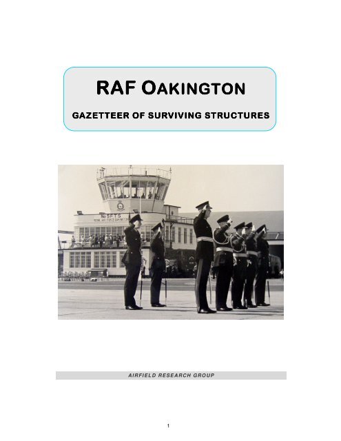
Plate 1: Watch Office with Meteorological Section and modern visual control room ................ vi<br />
Plate 2: Air Ministry bombing teacher inside the armoury ...................................................... viii<br />
Plate 3: <strong>RAF</strong> <strong>Oakington</strong>’s water tower ....................................................................................... 2<br />
Plate 4: Central heating station (55) .......................................................................................... 5<br />
Plate 5: Officers’ mess central block ......................................................................................... 9<br />
Plate 6: Officers mess, general view ......................................................................................... 9<br />
Plate 7: Officers mess, the dining room ................................................................................... 10<br />
Plate 8: Officers’ mess, the anteroom ..................................................................................... 10<br />
Plate 9: Officers’ mess (2) – rear view ..................................................................................... 11<br />
Plate 10: Officers’ mess (SE wing) .......................................................................................... 11<br />
Plate 11: Officers’ garages (3) ................................................................................................. 12<br />
Plate 12: Squash racquets court (4) ........................................................................................ 13<br />
Plate 13: Guard and fire party house (7) ................................................................................. 15<br />
Plate 14: Guard and fire party house (7) ................................................................................. 15<br />
Plate 15: Guard and fire party house (14) ............................................................................... 16<br />
Plate 16: A wooden bed inside one of the modern cells .......................................................... 16<br />
Plate 17: Station sick quarters (8) ........................................................................................... 18<br />
Plate 18: Station sick quarters and annexe (8 and 10) ............................................................ 18<br />
Plate 19: Decontamination annexe (10) .................................................................................. 21<br />
Plate 20: Decontamination annexe (10) .................................................................................. 21<br />
Plate 21: Station headquarters (14) ......................................................................................... 23<br />
Plate 22: Station headquarters – operations block (14) .......................................................... 24<br />
Plate 23: Station headquarters (14) ......................................................................................... 24<br />
Plate 24: Battalion Headquarters (14) ..................................................................................... 25<br />
Plate 25: Battalion Headquarters (14) ..................................................................................... 25<br />
Plate 26: Grocery shop and store (17) .................................................................................... 27<br />
Plate 27: Grocery shop and store (17), view from the empties yard ....................................... 27<br />
Plate 28: Petrol store (17A) ..................................................................................................... 28<br />
Plate 29: Unit store (18) ........................................................................................................... 29<br />
Plate 30: Barrack block type 8/84 (39) .................................................................................... 32<br />
Plate 31: Barrack block type 8/84 (19) .................................................................................... 33<br />
Plate 32: Barrack block type 8/84 (22) .................................................................................... 33<br />
iii
Plate 33: Barrack block type 8/84 (30) .................................................................................... 33<br />
Plate 34: Sergeants’ mess (central block) (24) ........................................................................ 36<br />
Plate 35: Sergeants’ mess (NW wing) (24) ............................................................................. 36<br />
Plate 36: Sergeants’ mess (24) general view .......................................................................... 37<br />
Plate 37: Annexe 24 ................................................................................................................ 37<br />
Plate 38: Combined dining room and institute (airmen’s mess) (31) ....................................... 40<br />
Plate 39: Combined dining room and institute (31) ................................................................. 40<br />
Plate 40: Combined dining room and institute (31) showing NCOs’ mess (Spar shop) .......... 41<br />
Plate 41: Combined dining room and institute (31 ................................................................... 41<br />
Plate 42: Ration store (32) ....................................................................................................... 42<br />
Plate 43: M&E plinth ‘A’ ........................................................................................................... 43<br />
Plate 44: General view of the MT section during army occupation ......................................... 44<br />
Plate 45: MT vehicle shed (40) ................................................................................................ 45<br />
Plate 46: MT vehicle shed (41) ................................................................................................ 45<br />
Plate 47: MT long bay (42) ...................................................................................................... 46<br />
Plate 48: MT vehicle shed and long bay (41 and 42 ............................................................... 46<br />
Plate 49: General view of MT vehicle sheds (40, 41 & 62) ...................................................... 47<br />
Plate 50: Articulated trailer shed (45) and extension ............................................................... 48<br />
Plate 51: Compressor House (47) ........................................................................................... 49<br />
Plate 52: AMWD offices (51) ................................................................................................... 50<br />
Plate 53: Contractor’s offices (51) ........................................................................................... 51<br />
Plate 54: Type B37 substation and pump house (51) ............................................................. 52<br />
Plate 55: Type B37 substation and pump house (51) viewed from the rear ............................ 53<br />
Plate 56: Gas defence centre and garages (51) ...................................................................... 53<br />
Plate 57: Gas defence centre and garages with water tank tower (51) ................................... 54<br />
Plate 58: Disinfector house (52) .............................................................................................. 55<br />
Plate 59: Central heating station (55) ...................................................................................... 57<br />
Plate 60: Central heating station – a view looking at the fuel store ......................................... 57<br />
Plate 61: Link trainer building (56) ........................................................................................... 59<br />
Plate 62: Link trainer building (56) ........................................................................................... 59<br />
Plate 63: Synthetic navigation trainer classroom (57) ............................................................. 60<br />
Plate 64: Aviation fuel installation (58) .................................................................................... 61<br />
Plate 65: 25 yard MG range (59) ............................................................................................. 62<br />
Plate 66: Marston sheds (61 and 62) ...................................................................................... 63<br />
Plate 67: Training theatre interior (63) ..................................................................................... 64<br />
Plate 68: Training theatre rear view (63) ................................................................................. 65<br />
Plate 69: Training theatre (63) front elevation ......................................................................... 65<br />
Plate 70: Main stores (66) front elevation showing fabric store ............................................... 67<br />
Plate 71: Main stores (66) rear view showing receiving area .................................................. 67<br />
Plate 72: Lubricant and inflammable store (68) ....................................................................... 69<br />
Plate 73: Lubricant and inflammable store (68) rear elevation ................................................ 69<br />
Plate 74: Armoury offices (70) ................................................................................................. 72<br />
Plate 75: Armoury Offices (70) front elevation ......................................................................... 72<br />
Plate 76: Armoury (70) AML .................................................................................................... 73<br />
Plate 77: Armoury (70) looking south ...................................................................................... 73<br />
Plate 78: Armoury (70) bombing target lighting rig .................................................................. 74<br />
Plate 79: Armoury (70) light fitting ........................................................................................... 74<br />
Plate 80: Store (73) north elevation (packing side) ................................................................. 76<br />
Plate 81: Parachute store (73), blind south elevation (storage) .............................................. 76<br />
Plate 82: Dinghy shed (74) ...................................................................................................... 77<br />
iv
Plate 83: Main workshops (76) ................................................................................................ 79<br />
Plate 84: Main workshops (76) ................................................................................................ 79<br />
Plate 85: T2 hangar (80) interior .............................................................................................. 80<br />
Plate 86: T2 hangars (79 and 80) ............................................................................................ 81<br />
Plate 87: T2 hangar (79) .......................................................................................................... 81<br />
Plate 88: ‘J’ type aircraft shed (83) .......................................................................................... 83<br />
Plate 89: ‘J’ type aircraft shed (93) door detail ........................................................................ 84<br />
Plate 90: ‘J’ type aircraft shed (93) interior .............................................................................. 84<br />
Plate 91: ‘J’ type aircraft shed (83) aerodrome elevation ........................................................ 85<br />
Plate 92: ‘J’ type aircraft shed (93) .......................................................................................... 85<br />
Plate 93: Night flying equipment store (86) ............................................................................. 86<br />
Plate 94: Nissen hut (95) aircraft armament store ................................................................... 88<br />
Plate 95: Nissen hut (95) aircraft armament store interior ....................................................... 88<br />
Plate 96: Varsity line crew building (98) .................................................................................. 89<br />
Plate 97: B’ Centre (150a) ....................................................................................................... 90<br />
Plate 98: B’ Controlled centre (158) ........................................................................................ 91<br />
Plate 99: Squadron dispersal building (510) entrance elevation ............................................. 92<br />
Plate 100: Squadron dispersal building (510) .......................................................................... 93<br />
Plate 101: Squadron dispersal building (510) interior view of classroom ................................ 93<br />
Plate 102: New gymnasium (514) ........................................................................................... 94<br />
Plate 103: New gymnasium (514) ........................................................................................... 95<br />
Plate 104: New gymnasium (514) interior of hall ..................................................................... 95<br />
Plate 105: CADF building (513) ............................................................................................... 97<br />
Plate 106: CADF building (513) ............................................................................................... 97<br />
Plate 107: SAA store (517) ...................................................................................................... 98<br />
Plate 108: VHF / UHF transmitter mast and generator building (518) ..................................... 99<br />
Plate 109: Exhaust silencer and ventilating column .............................................................. 100<br />
Plate 110: Open store ............................................................................................................ 101<br />
Plate 111: Sleeve streamer mast foundations ....................................................................... 102<br />
Plate 112: <strong>Airfield</strong> code letters, open day 1952 ..................................................................... 103<br />
Plate 113: <strong>Airfield</strong> code letters ............................................................................................... 104<br />
Plate 114: <strong>Airfield</strong> code letters ............................................................................................... 104<br />
Plate 115: WWII aircraft dispersal and post-war ASP ........................................................... 105<br />
Plate 116: BEFAB emergency arrester site ........................................................................... 106<br />
Plate 117: Practice bomb store and gas chamber (171) ....................................................... 108<br />
Plate 118: Fuzing point building (173) access road ............................................................... 109<br />
Plate 119: Bomb stores (186) lorry unloading ramp .............................................................. 111<br />
Plate 120: Bomb stores (186) ................................................................................................ 111<br />
Plate 121: Bomb stores (186) trolley loading platform ........................................................... 112<br />
Plate 122: Bomb stores site (187 to 189) .............................................................................. 113<br />
Plate 123: Component Store (199) ........................................................................................ 114<br />
Plate 124: FC Construction pillbox (444), continuous field of fire .......................................... 115<br />
Plate 125: Modern and old pillbox (458) ................................................................................ 116<br />
Plate 126: Type FW3/22 pillbox (458) ................................................................................... 117<br />
Plate 127: FW3/22 pillbox (442) ............................................................................................ 117<br />
Plate 128: FW3/22 pillbox (460) ............................................................................................ 118<br />
Plate 129: FC Construction pillbox (461) ............................................................................... 119<br />
Plate 130: FC Construction pillbox (443), interior .................................................................. 119<br />
Plate 131: FC Construction pillbox, interior ........................................................................... 120<br />
Plate 132: FC Construction pillbox and air-raid shelter ......................................................... 120<br />
v
Plate 133: FC Construction pillbox (443) ............................................................................... 121<br />
Plate 134: FC Construction pillbox (446) ............................................................................... 121<br />
Plate 135: Watch tower located near the perimeter fence ..................................................... 122<br />
Plate 136: Watch tower overlooking the airfield .................................................................... 123<br />
Plate 137: Watch tower at the front gate ............................................................................... 123<br />
Plate 138: Stanton arched air-raid shelter (509) .................................................................... 124<br />
Plate 139: Air-raid shelters 483 ............................................................................................. 125<br />
Plate 140: Air-raid shelters 493 ............................................................................................. 125<br />
Plate 141: Interior of Stanton shelter (509) ............................................................................ 126<br />
Plate 142: BCF hut, Site 3 ..................................................................................................... 127<br />
Plate 143: Arcon houses, Site 3 ............................................................................................ 128<br />
Plate 144: Metsec bridge ....................................................................................................... 129<br />
Plate 145: Outer marker ........................................................................................................ 130<br />
Plate 146: Glide path building ................................................................................................ 131<br />
Plate 147: VHF/ DF building .................................................................................................. 132<br />
Plate 148: Standby house ..................................................................................................... 132<br />
Plate 149: NAAFI families shop ............................................................................................. 133<br />
Plate 150: Blast shelter, decontamination centre and additional Nissen ward block ............. 156<br />
Plate 151: Decontamination centre Type ‘G’ ......................................................................... 156<br />
Plate 152: Watch Office with Meteorological Section (85) ..................................................... 157<br />
Plate 153: Watch Office with Meteorological Section (85) ..................................................... 157<br />
Plate 154: RC Church (160) .................................................................................................. 158<br />
Plate 155: RC Church (160) .................................................................................................. 158<br />
Plate 156: Standby house (179) ............................................................................................ 159<br />
Plate 157: Standby house (179) ............................................................................................ 159<br />
Plate 1: Watch Office with Meteorological Section and modern visual control room<br />
July 1976<br />
vi
PREFACE<br />
This report has been commissioned by WSP Environmental Ltd. to provide baseline information for<br />
the redevelopment of the former <strong>RAF</strong> <strong>Oakington</strong> site. It has taken as its main study area the land<br />
within the 1999 boundary of <strong>Oakington</strong> Barracks, although reference has also been made to outlying<br />
sites and structures outside the perimeter that relate to the history of the station; this includes<br />
structures south of the Longstanton Road. It provides information on the majority of buildings and<br />
structures erected on this site between 1939 and 1999 that were extant in 2004.<br />
<strong>The</strong> fieldwork was carried out by Paul Francis and Richard Flagg, the research and report writing<br />
was compiled by Paul Francis. Alex Brown completed the proof reading.<br />
Paul Francis, AIFA<br />
ARP<br />
9 Milton Road<br />
Ware<br />
Herts<br />
SG12 0QA<br />
Tel: 01920 420452<br />
E-Mail: paul.francis30@ntlworld.com<br />
ACKNOWLEDGEMENTS<br />
Richard Childes Atkins Defence<br />
Dave Allen Homes & Communities Agency<br />
Alex Brown <strong>Airfield</strong> <strong>Research</strong> <strong>Group</strong><br />
Richard Childes Atkins Defence<br />
Denis Corley <strong>Airfield</strong> <strong>Research</strong> <strong>Group</strong><br />
Graham Crisp <strong>Airfield</strong> <strong>Research</strong> <strong>Group</strong><br />
Aldon Ferguson <strong>Airfield</strong> <strong>Research</strong> <strong>Group</strong><br />
Richard Flagg <strong>Airfield</strong> <strong>Research</strong> <strong>Group</strong><br />
Les Gardner Atkins Defence<br />
John Hamlin <strong>Airfield</strong> <strong>Research</strong> <strong>Group</strong><br />
Paul Kitson Homes & Communities Agency<br />
Andrew Ricketts WSP Environmental<br />
Steve Wright Tenant Farmer<br />
COPYRIGHT<br />
WSP Environmental Ltd and <strong>Airfield</strong> <strong>Research</strong> <strong>Group</strong>, June 2011.<br />
All rights reserved. No part of this report may be reproduced or used in any<br />
form or by any means – photographic, electronic or mechanical, including<br />
photocopying, recording, taping or information storage and retrieval systems –<br />
without the prior permission in writing of the copyright holders.<br />
vii
Plate 2: Air Ministry bombing teacher inside the armoury<br />
(70) March 2011<br />
viii
1.1 Methodology<br />
1. METHODOLOGY AND SITE OVERVIEW<br />
This gazetteer is a stand-alone document that accompanies the <strong>Oakington</strong> History report. It<br />
covers all extant structures and these have been placed within six chapters, depending on<br />
building type and location.<br />
<strong>The</strong> building descriptions in this report conform to English Heritage’s Level 2 / 3 surveys as<br />
described in Understanding Historic Buildings – A Guide to Good Recording Practice (2006).<br />
<strong>The</strong> gazetteer is based on an earlier one compiled in 2004 but has been enhanced, due to<br />
more information becoming available and as the result of a subsequent series of field work<br />
exercises which were carried out between 21 February and 10 March 2011. It provides a record<br />
of structures at <strong>Oakington</strong> and is not a structural or condition survey. A DVD of images taken<br />
during both surveys and pdf files of building plans is included in support of this report.<br />
All buildings within the 1999 MOD boundary which were covered in the original report are<br />
included here regardless of whether they have been demolished in the intervening period<br />
between 2004 and 2011. This report, like the previous one, does not include the married<br />
quarters; however it does include the WWII domestic site No.3 and the remote sites of the<br />
post-war Illuminated Landing System.<br />
Descriptions are arranged in building numbered order but are also based on type so that similar<br />
structures are grouped together – for example the barrack blocks. Any building numbers<br />
missing in the sequence were demolished before 2004 but an attempt has been made to locate<br />
images of demolished buildings, and these can be found in Appendix 3. Each heading has a<br />
title followed by the Air Ministry drawing number and then a building number in brackets, as<br />
used in the schedule of buildings on record site plans 4542/44 and 6342/54. A ten figure grid<br />
reference (NGR) is included, taken from a set of 1:2500 scale Ordnance Survey maps<br />
(TL 4064-4164, TL 4065-4165, TL 4066-4166). In all cases the reference point is the building’s<br />
centre.<br />
<strong>The</strong> description of each building is based on both the primary source (which in most cases is<br />
the quoted drawing) as well as field work observations. In the text, room dimensions are shown<br />
in imperial units followed by the metric equivalent, displayed as millimetres and shown in<br />
brackets. Wall thickness is also shown in imperial values and in order to cut down on repetition<br />
the following millimetre equivalents apply:<br />
Inches 4.5 6 11 13.5 15 27<br />
Millimetres 114 152 279 343 381 686<br />
After the description there is a footprint dimension shown as a bullet point which is a nominal<br />
figure presented in decimal imperial units (metre equivalents are shown in brackets).<br />
<strong>The</strong> conclusion which accompanied the original report has been omitted as it no longer applies.<br />
• Appendix 1 is a table listing all buildings constructed between 1939 and 1955 and<br />
includes the status of the building in September 2004.<br />
• Appendix 2 is a table containing a room inventory dated 28 February 1941. It is based on<br />
an incomplete set of documents found in building 51.<br />
• Appendix 3 is a small collection of images of buildings demolished before the 2004<br />
survey.<br />
1
1.2 Site Overview<br />
In September 2004, the former <strong>RAF</strong> station at <strong>Oakington</strong> had survived with a large percentage<br />
of its WWII buildings and infrastructure within the main camp area still intact. <strong>The</strong> majority of the<br />
dispersed buildings outside the 1999 boundary were removed before 1979. Perhaps the biggest<br />
loss occurred during its time under the occupation of the army; this included the demolition of<br />
the watch office with met section, as well as the battle headquarters and a small number of<br />
airfield defensive structures. During this period two runways (one had already been removed)<br />
were also removed for the construction of the M11 motorway, leaving only a small length<br />
remaining for STOL aircraft.<br />
In 1989, new security fencing with six gates was installed around the perimeter of the domestic<br />
and technical areas, and in 1999 the domestic area was separated from the technical area by<br />
additional fencing. This arrangement is extant in 2011.<br />
What survives in March 2011 at the time of the survey includes most but not all of the buildings<br />
present in 2004, as well as the internal road network. Previous to the original survey, the<br />
majority of the domestic buildings had become part of the immigration centre, but the technical<br />
buildings were disused during this period (2000 to 2010). This disuse has had a visible negative<br />
impact on the condition of many structures, whereas the domestic buildings have fared much<br />
better.<br />
<strong>The</strong> March 2011 historical fieldwork was part of a number of different types of survey carried<br />
out by specialists to enable demolition: this commenced once the surveys had been completed.<br />
Plate 3: <strong>RAF</strong> <strong>Oakington</strong>’s water tower<br />
(March 2011)<br />
2
Fig 1: Site Plan<br />
3
Fig 2: Site Plan<br />
4
2. DOM ESTIC AND TECHNICAL B UILDINGS<br />
Plate 4: Central heating station (55)<br />
Entrance to tank tower detail (March 2011)<br />
5
2.1 Officers' Mess & Quarters (2)<br />
60 4 2 / 3 8 & 4 2 9 6 / 3 9 , N G R : T L 4 0 5 2 0 6 6 6 8 5<br />
2.1.1 Introduction<br />
A Bulloch, FRIBA, designed the original 1934 version (<strong>RAF</strong> expansion<br />
Scheme ‘A’) which became the standard officers' mess and single<br />
officers' quarters for operational <strong>RAF</strong> stations. His idea was to create<br />
a standard type design based around a common formal Neo-<br />
Georgian style; it would however include three sizes of mess. A<br />
choice of a particular size depended on the number of officers that were originally planned for<br />
the station: <strong>The</strong> three designs were:<br />
• Type ‘A’: Fighter aerodromes 26 to 35 officers in the mess such as at Church Fenton.<br />
• Type ‘B’: Fighter and medium bomber stations – 36 to 45 officers in the mess, as at<br />
Duxford (fighter) and Wyton.<br />
• Type ‘C’: Heavy bomber and army cooperation stations – 46 to 55 officers in the mess.<br />
Examples include Finningley, Dishforth and Catterick.<br />
Between 1934 and 1939 all new operational as well as some older <strong>RAF</strong> stations had a mess to<br />
one of these types. <strong>Oakington</strong> was a Scheme ‘M’ station and as such would have had a mess<br />
based on this letter code sequence, but by now the planned floor area allowed for each officer<br />
had been reduced due to the increase in officer establishment as a result of mobilisation.<br />
Types ‘A’ to ‘C’ were therefore replaced with types ‘D’ to ‘F’:<br />
• Type ‘D’: 60 officers based on the old type ‘A’. Examples unknown.<br />
• Type ‘E’: 65 officers based on the old type ‘B’. Examples unknown.<br />
• Type ‘F’: 70 officers based on the old type ‘C’. Known examples are <strong>Oakington</strong>, Ouston<br />
and Waterbeach (it is quite likely that all Scheme ‘M’ stations had a type ‘F’ mess and the<br />
other two versions were never actually built).<br />
<strong>The</strong> architect Frank Hawbest, who replaced Bulloch, also changed the roof construction to<br />
conform to the latest Air Ministry requirements for protection against near-miss bomb blast. All<br />
previous designs had a pitched roof of steel trusses which were boarded and tiled, but the<br />
<strong>Oakington</strong> example features a protected design of flat reinforced-concrete slab roof instead of<br />
the more common pitched design. It opened on 28 October 1940 (the station itself opened on<br />
1 July 1940). Today <strong>Oakington</strong> is the only type ‘F’ mess which has not been over-roofed with a<br />
modern pitched design erected over the original flat one.<br />
As with the original 1934 design, the complex incorporates a central element which functions as<br />
the public rooms such as the dining room and the kitchen area, while officers (married or<br />
unmarried, as officers’ married quarters were not built here until after WWII) were<br />
accommodated within two wings, one each positioned on either side of the mess block. <strong>The</strong><br />
complex is therefore designed on the internal dispersal principle whereby the central element –<br />
the dining room and recreational facilities – is separated from the accommodation wings by<br />
lengths of corridor. Messes planned under the later <strong>RAF</strong> schemes went one step further by<br />
having their quarters blocks a characteristic L-shaped plan-form instead of the traditional<br />
rectangular pattern of the earlier schemes.<br />
<strong>The</strong> aim of this internal dispersal of officers was to reduce the potential casualties from a single<br />
bomb dropped by an enemy aircraft . Another feature of this design is that the main corridor<br />
runs in a straight line, connecting with both wings at the extreme ends and with all mess<br />
facilities within the central block, as well as all the exits along its length. <strong>The</strong> short ends of the L-<br />
6
shaped corridor also terminate at exit points. Additionally the corridor walls are load bearing to<br />
withstand near miss bomb blast.<br />
2.1.2 Access<br />
<strong>The</strong> planning is based on a symmetrical arrangement whereby the main access to the front<br />
elevation is via a central tree-lined driveway, to a roundabout at the entrance. From here SE<br />
and NW access roads continue around both quarters blocks to meet at the officers’ garages<br />
and the kitchen / messmen’s yards at the rear of the central block. <strong>The</strong> main building is SW<br />
facing with SE and NW accommodation wings.<br />
<strong>The</strong>re is also a hedge line pedestrian access route from the guardhouse, the route of which has<br />
been straightened out in recent years.<br />
2.1.3 Central Block Ground Floor<br />
All public facilities are contained within the ground floor; there is a central entrance with loggia<br />
and a large hall with SE and NW corridors which together form the main corridor. To the NW is<br />
a billiard room and card writing room, and then the NW quarters wing. On the SE side of the<br />
hall is a large anteroom plus access to the mess (or dining room) which is at right angles to the<br />
main corridor. <strong>The</strong> extreme end of the corridor is the SE quarters wing. <strong>The</strong> only other mess<br />
facilities, which are all to the NE of the corridor, are a cloak room, toilets and mess president’s<br />
office.<br />
All other rooms on the ground floor are associated with the running of the mess complex, and<br />
are based around a kitchen block which extends out northwards from the main block. This has<br />
a large kitchen, scullery, two larders and other store rooms associated with the preparation of<br />
meals, including separate beer and wine cellars. <strong>The</strong> mess room is connected to the servery<br />
and wash-up rooms, a pantry and the kitchen.<br />
Access to other ancillary rooms within the complex for staff is via a central service corridor<br />
(aligned SE / NW) which joins with the main corridor by two passages. <strong>The</strong> remaining rooms on<br />
the ground floor are therefore for the wellbeing of the mess staff. <strong>The</strong>se include a messmen’s<br />
scullery and hall and mess waiters’ quarters, plus a waiters’ day room.<br />
Along the corridor are two lightwells located conveniently close to toilets within the central<br />
block. <strong>The</strong>se not only provided a flood of natural light into the complex but are also the sites for<br />
foul-drain inspection points. <strong>The</strong>re is a third lightwell between the lavatories and the service<br />
corridor.<br />
Outside at the rear of the central complex on the west side of the kitchen block is a messmen’s<br />
yard, outhouse and mess waiters’ yard, while on the east side is the kitchen yard, outhouse and<br />
a fuel store.<br />
2.1.4 Central Block Subway and Basement<br />
<strong>The</strong> main corridor, before it leaves the central building in either direction, has a 5 ft deep<br />
subway to carry the central heating pipes (feed and return) and primary hot water from either<br />
the underground boiler house and pump room, or from the district heating scheme. This<br />
arrangement fed radiators and hot-water outlets located throughout the complex.<br />
Accessed from the mess waiters’ yard is a basement boiler house and pump house. <strong>The</strong> pump<br />
house room is also connected to the subway below the main corridor. This originally housed<br />
two 420,000 BTU boilers and circulating pumps which provided hot water for heating, and one<br />
240,000 BTU boiler which provided a hot water service. <strong>The</strong> mains, sub-mains lighting boards<br />
and power circuits were also located in the basement.<br />
7
2.1.5 Central Block First Floor<br />
<strong>The</strong>re are two first floor blocks which are independent of each other. A central one located<br />
above the kitchen block is accessed from a small staircase annexe that extends out from the<br />
kitchen block. Upstairs there is a servants’ dormitory, rest room, bathroom and lavatory.<br />
<strong>The</strong> other first floor block is located above the messmen’s scullery and mess president’s office<br />
on the NW side of the central complex. It is accessed from a set of stairs in the messmen’s hall.<br />
Upstairs there are two bedrooms, a bathroom and a linen cupboard.<br />
2.1.6 SE and NW Wings<br />
<strong>The</strong> central mess block is SW with the main corridor running SE / NW. <strong>The</strong> link-detached<br />
accommodation wings are therefore aligned SE and NW to the central block. Each is designed<br />
to accommodate 22 officers and a number of servants within a two-storey, L-shaped plan-form<br />
building. Rooms are arranged on either side of a central corridor; there is also a bathroom,<br />
ablutions and toilet facilities on both floors.<br />
Officers of squadron leader or above had an additional sitting room arranged on the same side<br />
of the corridor, and these are separated from each other by a shared bathroom and lavatory<br />
facility. Senior officers also had a corner fireplace. Officers of junior rank had a single bedroom,<br />
although this was larger than the equivalent for a senior officer as its combined function was as<br />
a sitting room. Junior officers within each floor shared a bathroom and lavatory complex.<br />
2.1.7 Associated Structures<br />
Associated with the officers' mess and quarters complex is a terrace of lock-up garages (3), a<br />
squash racquets court (4), and a tennis court (12). Normally it would also be associated with a<br />
small estate of married officers’ quarters but the outbreak of WWII meant that these houses as<br />
originally designed were never built.<br />
2.1.8 Construction<br />
External walls are a mixture of 15 inch and 11 inch cavity brick, while internal walls are 9 inch<br />
and 4.5 inch brick. <strong>The</strong> roof is reinforced concrete slab (presumed to be made from ‘Smiths’<br />
patent fire-proof floor / roof units) carried on beams.<br />
2.1.9 Immigration Reception Centre<br />
Building 2 functioned as a families and single parent accommodation block.<br />
2.1.10 Status, March 2011<br />
<strong>The</strong> building survives as the only flat roofed, pre-war designed officers’ mess in the UK. All<br />
internal rooms, passages and yard buildings are present, which is an unusual feature of<br />
surviving (pre-war designed) officers’ messes in 2011. <strong>The</strong> building has not been extended and<br />
contains many original features including doors, fire places, bedroom cupboards and store<br />
cupboards. However the fenestration has unfortunately been spoilt by UPVC double glazing<br />
units, and the rain water goods are plastic.<br />
Footprint dimensions:<br />
Mess Block 143.83 ft by 122.37 ft (43.84 m by 37.30 m),<br />
Quarters block: ‘L-shaped 126.99 ft by 70 ft (38.71 m by 21.35 m), width is 32.27 ft (9.84 m)<br />
8
Plate 5: Officers’ mess central block<br />
March 2011<br />
Plate 6: Officers mess, general view<br />
March 2011<br />
9
Plate 7: Officers mess, the dining room<br />
March 2011<br />
Plate 8: Officers’ mess, the anteroom<br />
March 2011<br />
10
Plate 9: Officers’ mess (2) – rear view<br />
March 2011<br />
Plate 10: Officers’ mess (SE wing)<br />
March 2011<br />
11
2.2 Officers' Garages (3)<br />
59 8 7 / 3 9 , N G R : T L 4 05 5 2 6 6 7 3 0<br />
2.2.1 Introduction<br />
<strong>The</strong> access road to the officers’ mess and quarters terminates<br />
at a roundabout in front of the central block, where a road<br />
branches off on either side and continues around the side<br />
elevations of both quarter blocks. It then connects with either<br />
end of the officers' garages at the rear of the complex where it<br />
widens out into a car manoeuvring area in front of a suite of<br />
garages.<br />
2.2.2 Construction<br />
<strong>The</strong> original officers’ garages consist of a terraced block of 22 garages, constructed mainly of 9<br />
inch and 4.5 inch brick interior walls with a new single-pitched roof. In the mid-1960s another<br />
suite of eleven garages was built against the western end of the rear elevation and this is<br />
constructed of concrete block with brick end walls.<br />
2.2.3 Immigration Centre<br />
Building 3 was partly used as a garage and a store.<br />
2.2.4 Status, March 2011<br />
‘Garador’ door units have mainly been removed while the new garages are complete with their<br />
doors.<br />
Footprint dimensions: old garage 215.82 ft by 17.52 ft (65.78 m by 5.34 m).<br />
New garage 109.53 ft by 18.47 ft (32.38 m 5.63 m).<br />
Plate 11: Officers’ garages (3)<br />
March 2011<br />
12
2.3 Squash Racquets Court (4)<br />
66 5 9 / 3 9 , N G R : T L 4 06 0 5 6 6 6 6 9<br />
2.3.1 Introduction<br />
<strong>The</strong> squash racquets court is located behind the east officers’ quarters<br />
wing. It was designed by FH Lambert and is based on the original A<br />
Bulloch design of 1934. It consists of a lobby area and changing room/<br />
cloakroom with a hardwood staircase to a viewing gallery, and the<br />
main squash court playing area. Upstairs, the viewing gallery has a seating area and balcony.<br />
2.3.2 Construction<br />
Walls are 11 inch cavity brick with external piers, the interior of the playing area is cement<br />
rendered while above this is fair face brick. <strong>The</strong> corrugated roof covering and two skylights are<br />
carried on a pair of exposed steel trusses. This roof arrangement appears to be a deviation<br />
from that shown in drawing number 6659/39, probably for austerity reasons.<br />
2.3.3 Immigration Centre<br />
Building 4 was used as a store.<br />
2.3.4 Status, March 2011<br />
<strong>The</strong> building survives with both original steel windows present.<br />
Footprint dimensions: 41.26 ft by 24.08 ft (12.58 m by 7.29 m)<br />
Plate 12: Squash racquets court (4)<br />
March 2011<br />
13
2.4 Guard and Fire Party House (7)<br />
49 4 – 4 9 7 / 3 8 , N G R : T L 40 5 6 9 6 6 5 3 0<br />
2.4.1 Introduction<br />
<strong>The</strong> guard and fire party house occupies a position along the main<br />
drive. It faces SW and is set back on the northern side to allow the<br />
SHQ to face the main drive. <strong>The</strong> building opened on 6 October 1940<br />
(the station itself opened on 1 July 1940).<br />
It is a Scheme ‘M’ design, consisting of a single-storey brick and concrete structure with an<br />
internal planning based around a lozenge-shaped plan-form (the four corners are known as<br />
triangles which are architecturally interesting as they functional – either as external access<br />
points or as light wells).<br />
<strong>The</strong>re is a large 28 ft by 60 ft (8534 by 18288) centrally located exercise yard which also<br />
functions as a light well. Rooms are therefore arranged around the exercise yard.<br />
2.4.2 Room Arrangement<br />
As originally built the accommodation is split between civilian wardens, the fire party and<br />
personnel forming the station guard. <strong>The</strong> front elevation is symmetrical with a veranda, the roof<br />
of which is supported by four pairs of brick piers and at either end is a loggia. One of these<br />
originally had a telephone box but this has now been removed and repositioned. <strong>The</strong>re is a<br />
central entrance veranda, which is divided between the guardroom, followed by an NCO's<br />
room, SAA store and then a civilian warden's barrack area on the right.<br />
<strong>The</strong> NW side contains the guardroom while beyond this is the general detention room, a<br />
corridor with access to the exercise yard and service detention room, and lavatories for the<br />
guard. As originally constructed it was not possible to get access from here to the remainder of<br />
the building.<br />
From the civilian warden's barrack room at the SE end of the veranda there is an L-shaped<br />
corridor that forms a perimeter of the exercise yard. From here there is access to the fire party<br />
barrack room located at the rear of the building, and a lavatory / bathroom. Other rooms include<br />
a paint and repair shop, and the prophylactic treatment room. Both of these are accessed from<br />
the eastern triangle. <strong>The</strong> central part of the SE side elevation is the fire tender house which<br />
extends beyond the main building. <strong>The</strong> last room is a calorifier chamber, which is behind the<br />
service detention room and is accessed from the NW triangle.<br />
2.4.3 Internal Modifications<br />
<strong>The</strong> building underwent internal modification c.1975 whereby the open plan fire party barrack<br />
room was converted into four detention rooms, each having a small window. <strong>The</strong>y were<br />
accessed from a new covered way erected within the exercise yard, and a new wide corridor<br />
which connected with the L-shaped one. <strong>The</strong> prophylactic room was also modified with a new<br />
entrance from the former L-shaped corridor and its original entrance from the eastern triangle<br />
was bricked up. A new partition was also built inside the modified room. <strong>The</strong> function of these<br />
two rooms is unknown. <strong>The</strong> former civilian warden's room became guard quarters and the<br />
doorway to the L-shaped corridor was bricked up. <strong>The</strong> paint and repair shop became the fire<br />
section quarters.<br />
2.4.4 Construction<br />
External walls are 15 inch vented cavity brick with internal walls of 9 inch brick. Windows were<br />
originally two, three and ten pane steel casements, and metal grill windows within timber<br />
14
surrounds in the detention rooms. <strong>The</strong> main entrance had five-panel stout timber doors and the<br />
fire tender house had a steel roller shutter type door. <strong>The</strong> roof is 5 inches of reinforced concrete<br />
slab of protected roof design, the perimeter of which overhangs by 12 inches (0305).<br />
2.4.5 Immigration Centre<br />
Building 7 functioned as a secure unit and departure block.<br />
2.4.6 Status, March 2011<br />
Most windows have been replaced by UPVC types which are out of keeping with its<br />
architectural design.<br />
Footprint dimensions: 105.93 ft by 75.14 ft (32.29 m by 22.90 m).<br />
Plate 13: Guard and fire party house (7)<br />
March 2011<br />
Plate 14: Guard and fire party house (7)<br />
c.1997<br />
15
Plate 15: Guard and fire party house (14)<br />
September 2004<br />
Plate 16: A wooden bed inside one of the modern cells<br />
March 2011<br />
16
2.5 Sick Quarters (8)<br />
75 0 3 / 3 7 , N G R : T L 4 04 6 5 6 6 4 4 0<br />
2.5.1 Introduction<br />
<strong>The</strong> Scheme ‘M’ station sick quarters as built at <strong>Oakington</strong> is<br />
similar in architectural treatment and internal layout to the<br />
Scheme ‘L’ design of 1938, except that the parapet wall around<br />
the perimeter of the roof is omitted. A major difference to the<br />
earlier scheme is the design of decontamination annexe (10). As<br />
before the sick quarters is connected by a corridor from the side<br />
of the annexe which faces south-east.<br />
<strong>The</strong> building is SW facing, covering two stories with a central main entrance porch and hall with<br />
stairs to the floor above.<br />
Associated with the sick quarters is the decontamination annexe (10) located at the rear of the<br />
building, the decontamination centre (13) (now demolished) and the combined ambulance<br />
shelter and mortuary (11) which is also demolished.<br />
2.5.2 Ground Floor<br />
From the hall are two corridors, the NW one giving access to an accident reception area,<br />
kitchen, medical stores and medical NCO's office. <strong>The</strong> SE corridor gives access to a dental<br />
surgery, a consulting room, medical inspection area, office, dispensary and a waiting room used<br />
by personnel arriving via the decontamination annexe.<br />
2.5.3 First Floor<br />
Upstairs there is also a central longitudinal corridor. <strong>The</strong> rear half of the floor is entirely taken up<br />
with ablutions and toilets, and the front half contains an airmen’s’ ward (four beds), orderly<br />
room, observation ward (a single bed), and two separate single bed officers' wards.<br />
2.5.4 Extension (Building 9)<br />
At the end of 1943 and in keeping with sick quarters located on permanent <strong>RAF</strong> stations<br />
elsewhere, an additional ward block and dental surgery was built against the NW end elevation<br />
in temporary brick and Nissen construction. This work was carried out with reference to drawing<br />
number 3250/43.<br />
<strong>The</strong> extension consisted of a new entrance hall, connecting corridor, dental store and dental<br />
surgery in temporary brick, and a 30 ft (9144) span Nissen hut arranged mainly as a 16 bed<br />
ward but also having lavatories, bathroom, dirty linen store, ward equipment store, sluice room<br />
and duty room. <strong>The</strong> brick part is extant.<br />
2.5.5 Construction<br />
External walls of the original building are 15 inch vented cavity brick with concrete beams<br />
supporting a reinforced concrete slab roof. Windows were originally 12 pane timber casements<br />
on the ground floor and 16 pane timber casements at first floor level. A post-war, link-detached<br />
rendered brick extension (9) has been built against the NW side elevation which was the<br />
entrance hall to the Nissen hut ward block.<br />
2.5.6 Immigration Centre<br />
Building 8 was derelict during the period of the Immigration Centre.<br />
17
2.5.7 Status, March 2011<br />
All internal rooms are as-built.<br />
Footprint dimensions: 125.05 ft by 40.38 ft (38.12 m by 12.31 m)<br />
Plate 17: Station sick quarters (8)<br />
March 2011<br />
Plate 18: Station sick quarters and annexe (8 and 10)<br />
March 2011<br />
18
2.6 Decontamination Annexe (10)<br />
16 4 7 9 / 3 9 & 2 4 2 5 / 4 0 , N G R : TL 404 8 1 6 64 5 0<br />
2.6.1 Introduction<br />
<strong>The</strong> use of gas in war was outlawed by the Geneva Gas Protocol of<br />
1925 (both Germany and Britain were signatories), but its production<br />
and development were not. As a result the British Government, with<br />
its previous experience of the ease with which signed agreements<br />
were broken during hostilities, decided to develop gas weapons and<br />
design methods of protection against their use. This included the construction of specialised<br />
buildings so that in the event of such an attack, personnel who became gas casualties could<br />
receive first-aid treatment and get decontaminated. <strong>The</strong> decontamination centre and annexe to<br />
the sick quarters was designed to deal with most types of gas developed during WWI:<br />
lachrymatory agents, respiratory agents and blister agents.<br />
It was possible to protect oneself from many of the gases by wearing a respirator. Some gases<br />
had distinctive odours that gave sufficient warning of their presence to allow personnel to take<br />
cover inside a building or shelter. However mustard gas has only a faint smell of garlic and its<br />
symptoms are not always apparent until sometime after the attack. In liquid or vapour form, the<br />
skin can absorb mustard gas without the victim noticing. By the time irritation is felt, the agent<br />
has penetrated the surface of the skin and started to cause serious damage. <strong>The</strong>refore special<br />
warning posts with metal plates coated with gas detection paint were placed at intervals along<br />
pathways connecting with buildings; these would change colour when exposed to mustard gas.<br />
<strong>The</strong> basic idea was to get out of all contaminated clothing and dispose of it, then wash<br />
thoroughly and change into fresh clothing as soon as possible. If all this could be achieved<br />
within 20 minutes of the initial contamination, serious injury could be avoided.<br />
Two buildings were built at <strong>Oakington</strong> for the decontamination of personnel:<br />
Annexe to sick Quarters (10) for wounded male and female personnel.<br />
Decontamination centre type ‘G’ (13) for unwounded male and female personnel. This was<br />
demolished along with the ambulance garage and mortuary (11) in 1989, to allow the<br />
construction of a car park.<br />
<strong>The</strong> chief architectural difference between the sick quarters annexe and the decontamination<br />
centre is that the latter was a detached building. <strong>The</strong> annexe is also associated with the<br />
disinfector house (52) where the contaminated clothes would be taken for boiling.<br />
2.6.2 Operation<br />
Wounded personnel requiring treatment for conventional wounds as well as decontamination<br />
had to be cleaned and treated for the effects of the gas before entering the SSQ. A one-way<br />
system was in force whereby wounded personnel (either walking or as stretcher cases) would<br />
enter the annexe through one of two doorways located on the SE end elevation: men through<br />
the left and women the right). Here there is a path with a gentle slope that functions as a<br />
footbath of bleach solution. Guide rails (which are missing) were provided, as one of the effects<br />
of mustard gas is blindness. <strong>The</strong> first room is a reception area and undressing room where<br />
contaminated clothes are discarded through metal hoppers (these have been in-filled with brick)<br />
where they fall into bins which were placed against the SE elevation, below the hoppers. <strong>The</strong><br />
concrete floor and internal rendered walls were treated with sodium silicate solution and the<br />
floor has a drainage system to allow decontamination to be easily carried out. With the plant<br />
running this part of the building operated at ambient air pressure and therefore, during a gas<br />
19
attack, it was quite likely to be contaminated. To get into the shower and bleaching room where<br />
the internal air pressure was above ambient (to prevent mustard gas from entering this section<br />
as it is heavier than air), it was first necessary to enter an airlock. <strong>The</strong> airlock consists of two<br />
gas-tight doors separated by a gas-proof compartment – a wounded airman would enter the<br />
airlock, close the door behind, and then open the other door to enter the bleaching area.<br />
<strong>The</strong> bleaching room contained shower cubicles, sinks, bleach store, towel store, dirty towel<br />
store and W/Cs. First of all personnel were required to use the showers; these were arranged<br />
as a pair with a space between so that a person could wet himself under one, move into the<br />
space to soap himself and then wash off the soap in the next shower cubicle. After a thorough<br />
wash, the treatment could begin with the antidote to mustard gas – bleach. A specially prepared<br />
paste would be rubbed into the affected area and then wiped off after two minutes.<br />
After the bleaching room came a dressing area containing a clean clothes store and waiting<br />
area. From here a corridor connects with the waiting room inside the sick quarters which was<br />
accessed via another airlock.<br />
2.6.3 Construction<br />
<strong>The</strong> building design of the annexe at <strong>Oakington</strong> is completely different to annexes built to the<br />
earlier <strong>RAF</strong> schemes. This version is an austerity Scheme ‘M’ design that was much quicker to<br />
build than the permanent fully-protected types erected on the peace time stations. It consists of<br />
a windowless single-storey structure with a flat roof, which is interrupted by a full-width water<br />
tank house. Walls are cement-rendered internally, 13.5 inch solid brick supporting a roof of<br />
Sigwart precast concrete units. Internal walls are 9 inch brick. <strong>The</strong> buildings internal floor plan is<br />
mirrored to the original drawing; consequently the AC plant room and boiler house are<br />
positioned along the NE elevation towards the rear of the building and the male side is where<br />
the female side should be.<br />
2.6.4 Immigration Centre<br />
During the army occupation, building 10 was the headquarters of the local army cadet force. In<br />
1999 the unit moved into the NAAFI families shop (building 147) on the married quarter estate,<br />
Longstanton, which it shares with the local ATC unit (see building 17). During the Immigration<br />
Centre period, it was derelict.<br />
2.6.5 Status, March 2011<br />
<strong>The</strong> concrete footbaths survive and the pressure stabilisers are in-situ on the SE end wall. <strong>The</strong><br />
external and airlock gas-tight doors are all original and even retain their rubber seals, but not<br />
their door furniture. All internal rooms are as-built.<br />
Footprint dimensions: 91.48 ft by 37.98 ft (27.88 m by 11.58 m).<br />
20
Plate 19: Decontamination annexe (10)<br />
March 2011<br />
Plate 20: Decontamination annexe (10)<br />
Note the footbaths, three pressure stabilizers and three openings (bricked up) for dirty clothing.. March 2011<br />
21
2.7 Station Headquarters and Operations Block (14)<br />
16 6 9 0 / 3 9 , N G R : T L 40 5 9 5 6 6 4 5 0<br />
2.7.1 Introduction<br />
Occupying a prominent position facing the main entrance (NW facing)<br />
is the station headquarters (SHQ). It is of protected roof design with a<br />
flat fire-proof concrete slab roof and is divided into two main parts,<br />
consisting of the SHQ at the front and an operations block at the rear.<br />
It is a Scheme ‘M’ version, based on the earlier pitched roof design by<br />
A Bulloch in 1934 and its architectural treatment is of a formal Neo-Georgian style.<br />
<strong>The</strong> SHQ at <strong>Oakington</strong> has only two storeys and does not include the second storey offices for<br />
the Meteorological Officer. This is probably because the third storey was the result of a<br />
deviation drawing, and the outbreak of WWII prevented the construction of the additional floor.<br />
It opened for business on 9 November 1940 and six days later the operations room opened (the<br />
station itself opened on 1 July 1940).<br />
2.7.2 Ground Floor (SHQ)<br />
<strong>The</strong> ground floor is based around a T-shaped plan-form, with a central entrance and hall and a<br />
central corridor running longitudinally with rooms on either side. Another corridor (at rightangles)<br />
gives access to toilets and a staircase, before it ends at the operations block.<br />
<strong>The</strong> right-hand wing had two orderly rooms and a waiting room. <strong>The</strong> single-storey part of this<br />
wing had offices for the Engineer Officer and his clerk; another for the Adjutant and the final one<br />
was for the Commanding Officer.<br />
<strong>The</strong> other wing housed offices for the Chief Accounting Officer and his clerks and another one<br />
for a Sergeant Major. <strong>The</strong> final room (single-storey) was for stores and accounts clerks. This<br />
large room had a veranda against the rear elevation for airmen to stand under to receive<br />
payment through one of three sliding windows.<br />
A single-storey kitchen annexe (room G24) has been built in part of the space between the<br />
SHQ and ops room on the SE side, its access being a former entrance to the operations block.<br />
2.7.3 First Floor<br />
<strong>The</strong> first floor also has a T-shaped plan-form but on a much smaller scale than the floor below.<br />
<strong>The</strong> front section had a library and two lecture rooms while the rear section had a toilet and an<br />
office for the Education Officer and his clerk.<br />
2.7.4 Operations Block<br />
<strong>The</strong> operations block is located at the rear of the SHQ with access either from the corridor<br />
linking with the hallway at the front of the SHQ, or a side entrance and hall which was the<br />
official entrance to the block. <strong>The</strong> access to the block itself was through heavy steel doors that<br />
led to a corridor running around four sides of a light well. Rooms included offices for Signals<br />
Officer and CO, the operations room, traffic office, wireless room, a room containing emergency<br />
110 volt supply batteries and the telephone exchange<br />
<strong>The</strong> operations block was originally surrounded by a 10 ft 7 in (3226) high traverse, 3 ft (0914)<br />
thick hollow blast wall which had a cavity filled with sand and gravel. As this is one of the few<br />
operations blocks that has an additional operations room (room G38) for the local anti-aircraft<br />
defence unit, this annexe has been built over part of the area normally covered by the route of<br />
the blast wall. It was therefore diverted around the new annexe, before continuing on its normal<br />
22
oute around the operations block. <strong>The</strong> annexe has been built to a similar standard to the<br />
original block, including the protected roof, and was completed at the same time.<br />
<strong>The</strong> structure rises to 1.5 storey height but the accommodation is only single-storey with a thicksection<br />
roof, followed by a void and then a thin-section upper roof. <strong>The</strong> void is filled with a layer<br />
2 ft 6 in (0762) of sand and gravel, and on top of this is another 2 ft (0609) of just gravel. This<br />
arrangement, along with the traverse blast walls, offered personnel inside the block a fair<br />
amount of protection against incendiary bombs and near miss bomb blast.<br />
2.7.5 Construction<br />
Exterior walls are vented cavity 15 inch brick; internal walls are either 9 inch brick or 13.5 inch<br />
brick (lateral corridor serving the operations block). Floors and roof are reinforced concrete<br />
supported by cased steel beams.<br />
2.7.6 Immigration Centre<br />
Building 14 functioned as an administration and control centre.<br />
2.7.7 Status, March 2011<br />
Most SHQs have had a third storey constructed for the Met Officer so it is unusual to see an<br />
SHQ without one. <strong>The</strong> building retains its flat roof, and its internal room arrangement is largely<br />
as-built, but it has lost its original windows. Outside the blast wall that once protected the<br />
operations block has been removed (apart from a small section) and has been replaced on the<br />
SE elevation by the kitchen and AA operations room annexes. Inside the operations room<br />
complex, there has been some remodelling of rooms. <strong>The</strong> most obvious is the light well being<br />
converted into a useable room (G32), and the operations room itself (G36) has been made<br />
smaller with the addition of a new corridor (G37).<br />
Footprint dimensions:<br />
SHQ – 149.74 ft by 35.54 ft (45.64 m by 10.83 m), maximum width 68.95 ft (20.94 m).<br />
Ops – 86.17 ft by 42.20 ft (26.26 m by 12.86 m).<br />
Plate 21: Station headquarters (14)<br />
March 2011<br />
23
Plate 22: Station headquarters – operations block (14)<br />
Note the extra AA operations room annexe in the foreground (March 2011)<br />
Plate 23: Station headquarters (14)<br />
March 2011<br />
24
Plate 24: Battalion Headquarters (14)<br />
c.1997<br />
Plate 25: Battalion Headquarters (14)<br />
c.1997<br />
25
2.8 Grocery Shop & Store (17)<br />
17 3 6 8 / 3 9 , N G R : T L 40 7 6 5 6 6 4 9 0<br />
2.8.1 Introduction<br />
<strong>The</strong> grocery shop and store is located behind the dining room and<br />
institute and was originally operated by the NAAFI organisation.<br />
Designed by Frank Hawbest the building is single-storey, originally<br />
with a rectangular shaped plan-form, but was extended during WWII to include a NAAFI staff<br />
quarters annexe and now has an L-shaped plan-form.<br />
It consists of a shop at one end served by an external entrance lobby on the NW end wall. A<br />
customer would enter the shop through this lobby, order the goods at the counter and the sales<br />
person would fetch the goods from the adjacent grocery, bacon stores and local produce store.<br />
<strong>The</strong> NAAFI staff quarters extension was built against the SW elevation at the shop end of the<br />
building. After the grocery store and local produce store was a covered yard with lavatory, and<br />
then a covered shed area. Both of these are now a part of the main building.<br />
2.8.2 Construction<br />
External walls are 11 inch cavity brick supporting a roof of reinforced concrete slab. Windows<br />
were three or eight pane steel casements with guard bars. Internal walls are 4.5 inch and 9 inch<br />
brick. <strong>The</strong> roof of the covered sheds was single-pitch timber covered with corrugated asbestos<br />
sheeting.<br />
2.8.3 Immigration Centre<br />
It is believed that from the mid-1970s until 1999, this building functioned as the headquarters<br />
building for 2524 Squadron, Air Training Corps. In April 1999 the unit moved into the NAAFI<br />
families shop (building 147) on the married quarter estate, Longstanton, which it shares with an<br />
army cadet unit. During the Immigration centre period, Building 17 functioned as the<br />
maintenance staff store.<br />
2.8.4 Status, March 2011<br />
All rooms appear to be original.<br />
Footprint dimensions: 87.47 ft by 53.27 ft (26.66 m by 16.24 m).<br />
26
Plate 26: Grocery shop and store (17)<br />
March 2011<br />
Plate 27: Grocery shop and store (17), view from the empties yard<br />
March 2011<br />
27
2.9 Petrol Store (17A)<br />
B u i l d i ng T ype ?, NG R ?<br />
2.9.1 Introduction<br />
<strong>The</strong> petrol store appears to have been erected on the concrete floor<br />
slab of a demolished building. It consists of a windowless concrete<br />
post and panel store with a single-pitch roof.<br />
2.9.2 Construction<br />
Construction is of reinforced concrete posts or stanchions at 4 ft (1219) centres with a steel<br />
truss that is bracketed and bolted to the post. Wall infilling is concrete panels 3 ft 10 in by 1 ft 4<br />
in (1168 by 0406) which are fixed into position by steel brackets. <strong>The</strong> panels only go up to the<br />
underside of the truss; these are followed by a wooden framed and clad soffit board. Roof<br />
cladding is corrugated asbestos sheeting.<br />
2.9.3 Immigration Centre<br />
Building 17 A was derelict during the Immigration Centre period.<br />
2.9.4 Status, March 2011<br />
<strong>The</strong> building used to have a large opening but this has been made smaller and in-filled with<br />
concrete blocks.<br />
Footprint dimensions: 20.16 ft by 8.10 ft (6.15 m by 2.47 m).<br />
Plate 28: Petrol store (17A)<br />
March 2011<br />
28
2.10 Unit Ammunition Storehouse (18)<br />
N G R : TL 408 1 0 6 65 8 2<br />
2.10.1 Introduction<br />
<strong>The</strong> new unit ammunition storehouse, which is a generic Army<br />
design from 1973, was built c.1976. It consists of a terrace of three<br />
store cubicles, and a receipts and issue room which is separated<br />
from the storehouses by a 27 inch thick wall. Along the front<br />
elevation is a veranda. Full height earthwork traverses and a security fence with lighting stand<br />
posts surround the storehouse.<br />
2.10.2 Immigration Centre<br />
Building 18 is located outside the area used by the Immigration Centre.<br />
2.10.3 Status, March 2011<br />
When viewed, the building was found to be in a partially demolished (see image below).<br />
Footprint dimensions: 48.93 ft by 22.92 ft (15 m by 7 m).<br />
Plate 29: Unit store (18)<br />
March 2011<br />
29
2.11 Barrack Blocks (19–22, 25, 26, 30, 39)<br />
T ype 8/ 8 4 – 1 1 3 4 / 3 8 ( 1 9 – 2 2 , 2 5 , 2 6 & 3 0 ) , T ype 8/ 56 ( 3 9 )<br />
N G R :<br />
( 1 9 ) T L 40 6 9 5 6 6 4 8 0 ( 2 0 ) T L 4 0 6 7 5 6 6 4 1 2<br />
( 2 1 ) T L 40 6 2 5 6 6 3 7 1 ( 2 2 ) T L 4 0 5 6 5 6 6 3 5 5<br />
( 2 5 ) T L 40 6 9 0 6 6 2 1 5 ( 2 6 ) T L 4 0 7 1 0 6 6 2 8 0<br />
( 3 0 ) T L 40 7 5 9 6 6 3 2 2 ( 3 9 ) T L 4 0 8 2 5 6 6 3 3 3<br />
2.11.1 Introduction<br />
As a Scheme ‘M’ station <strong>Oakington</strong> was planned from the beginning with seven examples of<br />
barrack block type 8/84 and a single 8/56 block; the station is therefore without older style<br />
barrack blocks. Both building types were designed under Scheme ‘L’. <strong>The</strong> majority of expansion<br />
period stations belonging to earlier schemes were originally designed and planned without<br />
these types of barracks as they had not yet been conceived. After mobilisation these stations<br />
were further extended to accommodate extra airmen, and so additional land had to be<br />
requisitioned so that the new buildings could be built. By only having this design of barrack<br />
block, Scheme ‘M’ stations tended to be smaller than the earlier stations.<br />
<strong>The</strong> barrack blocks at <strong>Oakington</strong> were constructed between 1940 and 1941. JH Binge, ARIBA<br />
had designed this building type in 1938 as a protected-roof design barrack block. It and its<br />
architectural treatment are based on a formal Neo-Georgian style, but it is less decorative than<br />
previous <strong>RAF</strong> designs. Each block was designed to accommodate eight NCOs and either 84 or<br />
56 airmen. <strong>The</strong> ground floor had three NCO bedrooms while the first floor has five, the space<br />
on the ground floor where the extra rooms should be is part of the hall; it is the elevation which<br />
has the larger hall that is the front of the building.<br />
A number of improvements came about during 1938 under Scheme ‘L’ when it was decided that<br />
the floor area per man in barrack rooms should be increased from 67sq ft to 69 sq ft. <strong>The</strong><br />
ceiling height was also reduced from 10 to 9 ft (3048 to 2743), and the number of men per room<br />
was reduced to a maximum of 12. <strong>The</strong> provision of a sitting room for entertainment and a utility<br />
room for cleaning equipment were amongst other additions.<br />
<strong>The</strong> H-shaped plan-form was chosen as it is the ultimate design in internal dispersal for passive<br />
defence of personnel within a single building: it avoided concentrating large numbers of airmen<br />
in one wing. One block covers a similar floor area as two of the older style T-shaped barrack<br />
blocks and the H-shaped plan is essentially two T-shaped blocks joined together by their<br />
ablution annexes.<br />
All these improvements led to new two-storey type-designs known as the 8/56 (eight NCOs and<br />
56 airmen) and 8/84 with both flat and pitched roofed versions. Buildings to this new standard<br />
were erected at all Scheme ‘L’ and ‘M’ <strong>RAF</strong> stations (such as <strong>Oakington</strong> and Waterbeach) as<br />
well as to supplement existing accommodation at the stations built under earlier schemes. With<br />
the outbreak of WWII the sitting room became an additional barrack room for another 12<br />
airmen, making a total for the larger version of 96 airmen and eight NCOs in each block.<br />
<strong>The</strong> design is essentially a 29 ft 7 in by 98 ft 6 in (9017 by 30023) central unit which is common<br />
to all designs within this group of structures. <strong>The</strong>re is a longitudinal corridor with a hall and<br />
staircase at either end with NCOs' bedrooms and ablution facilities such as cleaning, drying<br />
rooms and toilets. At either end of the central unit are two open-plan wings, each for eight or 12<br />
airmen which gives the building its characteristic H-shaped plan-form.<br />
30
2.11.2 Air-Raid Shelter Provision<br />
Another characteristic of the new design was that the earlier versions included a basement<br />
emergency refuge located below the hall and one of the NCO’s bedrooms. <strong>The</strong> shelter is built of<br />
9 inch thick concrete and has a series of four 3 inch diameter steel columns along the centre<br />
giving additional support to the roof. <strong>The</strong> seating area has an internal width of 11 ft and a length<br />
of 20 ft (6096). Along the side walls were seats for ten personnel and along the centre was<br />
another seating nine (a total of 40 personnel); a cubicle for a chemical toilet was also provided.<br />
Gas-tight metal doors and a narrow escape passage having a minimum length of 25 ft (7620)<br />
with air-lock led to a point clear of the building. This internal facility however was not included<br />
within the blocks at <strong>Oakington</strong> and Waterbeach. Instead detached Stanton segment type airraid<br />
shelters were provided at a short running distance from each block, and in all cases the<br />
shelters are aligned on the centre-line (corridor) of the barrack block. <strong>The</strong> reason for this<br />
omission may have either been because of the high water table or that the stations were being<br />
built under war-time conditions, or maybe a combination of both. Another characteristic of the<br />
earlier blocks is the front elevation has rounded artificial stone columns supporting a weather<br />
canopy over the entrance. At <strong>Oakington</strong> this has been omitted and both entrances feature brick<br />
ends instead.<br />
2.11.3 Construction<br />
<strong>The</strong> eight buildings erected at <strong>Oakington</strong> are flat roofed and they still retain these, while at the<br />
majority of stations pitched roofs have been added over the originals. <strong>The</strong> <strong>Oakington</strong> buildings<br />
are arranged in a symmetrical grid like layout based around the intended central parade<br />
ground, which was never actually built.<br />
Exterior walls are vented cavity 15 inch brick with 9 inch internal walls. Windows were originally<br />
four, nine, ten and 16 light steel casements with continuous reconstructed stone sills, main<br />
doors were four-panel timber double units, but windows and doors have since been replaced.<br />
<strong>The</strong> first floor and roof are constructed of reinforced concrete slab corresponding to the<br />
protected roof design, the perimeter of which over hangs by 12 inches (0304).<br />
2.11.4 Change of Use<br />
Around 1948, building 22 had briefly became the No.2 officers’ mess, but it was then handed<br />
over to the sergeants for their new mess as their own mess had been requisitioned by officers<br />
as their new mess annexe. <strong>The</strong> open plan nature of the ground floor barrack rooms was<br />
retained and these became the public rooms (anteroom, billiard room, anteroom / bar / lounge<br />
and mess room respectively). A single-storey 11 inch brick kitchen and yard extension was built<br />
in the space between the NW – SE wings which contained a servery, mess man’s bedroom,<br />
wash up, kitchen, two food preparation rooms, larders and a staff dining room. Outside in the<br />
kitchen yard is a two bay outhouse. Upstairs, each open plan barrack room was converted into<br />
six bedrooms which including the former NCO’s bedrooms, making a total of 24 bedrooms for<br />
officers. Around January 1970 another extension 40 ft by 14 ft (12192 by 4267) was built in 11<br />
inch cavity brick against the NE wing (anteroom) and then another similar one on the other side<br />
but the details of these are unknown.<br />
Around 1951, the barrack rooms of Building 21 were converted into small single rooms and<br />
these were used as overflow accommodation for the sergeants’ mess: firstly on the ground<br />
floor, then in the late 1960s to include the top floor.<br />
By April 1969 the remaining six barrack blocks had not been converted, although only three<br />
(Buildings 20, 26 and 30) were actually used to accommodate airmen. Building 19 was in use<br />
by the Education Section and Building 39 was used as the AFTS Ground Instruction School.<br />
31
Building 25 was mainly empty, although one wing on the top floor was in use as the offices for<br />
the Standards Squadron; this building was also used to meet the station’s temporary<br />
commitments such as Air Training Corp Cadet Camps.<br />
2.11.5 Immigration Centre<br />
Buildings 19, 20, 26, 30 and 39 were all used as residential blocks, building 21 was an interview<br />
and medical block, building 22 was the detainee reception unit as well as the offices of the UK<br />
Immigration Agency. Building 25 was the offices for refuge legal representatives.<br />
2.11.6 Status, March 2011<br />
Buildings 19, 20, 23, 26 and 39 retain their open-plan barrack rooms – although in all cases<br />
UVPC windows have replaced the original metal casements. Buildings 20 and 26 have lost their<br />
cast iron rain water goods which have been replaced in plastic while the others have retained<br />
most of the original exterior fittings. All doors except for lavatory doors have been replaced with<br />
modern fire-proof examples.<br />
Buildings 21 22, and 25 have had their barrack rooms subdivided. Windows are now UPVC<br />
types, rain water and waste pipes are mostly cast iron although a few plastic examples are<br />
present. Internal doors are mainly modern fire-proof examples except for lavatory doors.<br />
Footprint dimensions: 114.29 ft by 99.61 ft (34.83 m by 30.36 m) (Type 8/84).<br />
Plate 30: Barrack block type 8/84 (39)<br />
All March 2011<br />
32
Plate 31: Barrack block type 8/84 (19)<br />
Plate 32: Barrack block type 8/84 (22)<br />
Plate 33: Barrack block type 8/84 (30)<br />
33
2.12 Sergeants' Mess & Quarters and<br />
WAAF Changing Room Annexe (23 & 24)<br />
M e s s 1152 7 / 3 8 ( 2 3 ) NG R T L 40 6 2 0 6 6 2 8 0 ,<br />
C h a n g i n g R o o m ( 2 4 ) NG R : T L 4 0 6 4 9 6 6 2 7 7<br />
2.12.1 Introduction<br />
<strong>The</strong> sergeants' mess and quarters as built at <strong>Oakington</strong> is the<br />
largest example of the pre-war designs and is based on the<br />
scale 170/17 which represents a mess hall for 170 sergeants<br />
and 17 bedrooms in the central block. This scale contrasts with<br />
sergeants messes elsewhere such as at <strong>RAF</strong> Bassingbourn,<br />
Honington and Wyton which were built to the scale of 116/14.<br />
<strong>The</strong> building was designed by Frank Hawbest and is based on an earlier one by JH Binge. It is<br />
a Scheme ‘M’ version with a protected roof. <strong>The</strong> example at <strong>Oakington</strong> is SW facing consisting<br />
of a two-storey combined central mess and quarters block flanked at the extreme ends (SE and<br />
NW wings) by additional quarters which are link-detached to the central block by corridors. <strong>The</strong><br />
complex is therefore designed on the internal dispersal principle whereby the central element –<br />
the dining room and recreational facilities, is separated from the accommodation wings by<br />
lengths of corridors with the idea of localising the effects of damage by a single bomb . Another<br />
feature of this is the corridor which runs full width connecting with both wings at the extreme<br />
ends and all mess facilities within the central block as well as all exits (along its length). <strong>The</strong><br />
corridor also has a 5 ft (1524) deep subway to carry the central heating pipes (feed & return)<br />
and primary hot water from the District Heating Scheme.<br />
2.12.2 Air-Raid Shelter Provision<br />
Another feature of its design is an underground refuge located beneath the entrance hall with<br />
an escape tunnel to a point clear of the building. This feature was omitted at <strong>Oakington</strong> and<br />
above ground air-raid shelters were instead placed at either end of the complex.<br />
2.12.3 Ground Floor (central block)<br />
<strong>The</strong> public rooms on the ground floor of the central block are based on a T-shaped plan-form<br />
with a central entrance hall with the main corridor running east-west. <strong>The</strong> hall has stairs to the<br />
quarters above and beyond this is an inner hall leading to the mess room. On the east side of<br />
the hall is the anteroom, while to the opposite side are ablutions and a billiard room. Kitchen<br />
facilities are located within an L-shaped annexe built on the east side of the mess room. This<br />
contains a large kitchen, a scullery, cook’s room, servery, beer store and an office.<br />
2.12.4 Yard<br />
On the east side of the kitchen annexe are two yards, one open and the other having outhouses<br />
used as stores and a larder. One of these is Building 24 which appears to be wash-up<br />
2.12.5 First Floor (central block)<br />
Sergeants' quarters on the first floor consists of 17 bedrooms, ablutions, toilets, a cleaning room<br />
and a drying room.<br />
2.12.6 Wings<br />
<strong>The</strong> link-detached two-storey quarters blocks were designed on the same internal dispersal<br />
policy as the mess. <strong>The</strong>y are therefore planned on an L-shaped plan-form with the foot of the L’<br />
facing away from the central complex. Each block could accommodate 22 senior NCOs and<br />
34
had ablution facilities similar to the first floor of the central block. Both floors have a central<br />
corridor with rooms on either side.<br />
2.12.7 Construction<br />
Exterior walls are 15 inch vented cavity brick with the inner corridor wall of 11 inch cavity brick.<br />
Other internal walls are mainly 9 inch brick with some 4.5 inch brick room partitions. Windows<br />
were originally five or 12 pane steel casements at first floor level and either eight or 16 pane<br />
steel casements on the ground floor. <strong>The</strong> building incorporates a flat protected roof design of<br />
reinforced concrete slab.<br />
<strong>The</strong> quarters blocks are of similar construction but windows were 12 pane steel casements for<br />
both floors on the outer facing elevations. Inner facing elevations had either four or eight pane<br />
steel casements. Bedroom partitions and corridor are 4.5 inch brick.<br />
2.12.8 Change of Use<br />
In 1948 due to the increased numbers of officers on the station, it became necessary to evict<br />
sergeants from their mess and they moved into new premises in Buildings 21 (quarters) and 22<br />
(mess and quarters). <strong>The</strong>ir former mess then became an annexe of the officers’ mess, (possibly<br />
used on a hotel basis for officers engaged in Operation Plain Fare and who required quarters<br />
for a short duration). It became known as the No.2 officers’ mess and the building continued in<br />
this form until at least 1970, when it reverted back to sergeants’.<br />
2.12.9 Immigration Centre<br />
Building 23 was derelict during the immigration centre occupation of the domestic area.<br />
2.12.10 Status, March 2011<br />
All windows have been replaced which are not in keeping with its architectural design.<br />
Footprint dimensions: central block 140.47 ft by 101.89 ft (42.82 m by 31.06 m), ‘L-shaped<br />
quarters 99.60 ft by 76.58 ft (30.36 m by 23.34 m) (width is 31.63 ft) (9.64 m).<br />
2.12.11 WAAF Changing Room Annexe 24<br />
Located at the rear of the sergeants mess central block and part of the curtilage of that building<br />
is building 24, a small detached single-storey WAAF changing room annexe (as identified on<br />
site plan 6342/54). It is constructed of 4.5 inch brick with a concrete slab roof and has been built<br />
onto a concrete raft with a drainage channel along the front, the floor is quarry tiled and the<br />
internal walls are tiled full height. <strong>The</strong> doors and window glazing units are missing.<br />
It consists of a pair of rooms separated by a brick dividing wall (8 ft by 6 ft 9 in and 8 ft by<br />
5 ft 3 in) (2438 by 2057 and 2438 by 1600), ceiling height is 7 ft 5 in (2260).<br />
Footprint dimensions: 8.73 ft by 12.31 ft (2.66 m by 3.75 m).<br />
35
Plate 34: Sergeants’ mess (central block) (24)<br />
March 2011<br />
Plate 35: Sergeants’ mess (NW wing) (24)<br />
March 2011<br />
36
Plate 36: Sergeants’ mess (24) general view<br />
March 2011<br />
Plate 37: Annexe 24<br />
March 2011<br />
37
2.13 Combined Dining Room & Institute (31),<br />
WAAF Changing Room Annexes (33 & 34)<br />
D i n i n g R o o m 80 6 0 / 3 8 , N G R : T L 40 7 6 0 6 6 4 10<br />
A n n e x es ( 3 3 ) NG R : T L 40 82 6 6 6 3 8 8<br />
( 3 4 ) N G R: T L 40 8 0 0 6 6 4 0 0<br />
2.13.1 Introduction<br />
In 1934 it became general policy in the interests of economy, good<br />
architectural design and grouping that the traditionally separate<br />
dining room and institute buildings should be combined as one<br />
structure. Designs were prepared that were suitable to varying numbers of personnel as<br />
required. <strong>The</strong> new structures were planned on two floors with a vertical division between the<br />
dining and institute areas whereby the former consisted of two separate dining rooms, one on<br />
the ground floor and the other on the floor above. Some institute function rooms also required a<br />
NAAFI service and these were located on the ground floor, and games and other sitting rooms<br />
were positioned at first floor level. This combination allowed for dignified and well-proportioned<br />
buildings that enjoyed a centralised location overlooking the parade ground, and which provided<br />
an attractive architectural grouping with the adjacent barrack blocks.<br />
<strong>The</strong> internal planning is based on two-storey dining and institute facilities with a single-storey<br />
kitchen area at the rear of the building. <strong>The</strong>re is also a NAAFI staff quarters located at first floor<br />
level above a covered way leading into the kitchen yard.<br />
Designed by JH Binge to accommodate up to 800 corporals and airmen, the building has a<br />
rectangular-shaped plan-form, but in order that the dining areas could be arranged as large<br />
open-plan rooms the main access points have been positioned within two projecting two-storey<br />
entrance halls. This particular design replaced an earlier one (such as at Scampton) with<br />
inboard entrance halls whereas this larger version has projecting entrance halls positioned on<br />
the either of the front elevation.<br />
<strong>The</strong> facility is positioned at the head of the intended parade ground (which was never built). <strong>The</strong><br />
front elevation is therefore SW facing and this part of the building is the two-storey mess facility.<br />
Behind this is the single-storey kitchen area with a small second storey block at the rear to<br />
provide staff accommodation. <strong>The</strong> building opened on 16 November 1940 (the station itself had<br />
opened on 1 July 1940).<br />
2.13.2 Ground Floor – recreation facilities<br />
<strong>The</strong> right-hand entrance annexe was originally arranged open plan, with stairs to the floor<br />
above and an open area for use as a cloak room. <strong>The</strong> left-hand entrance annexe, whilst the<br />
same floor area as the other, also contained lavatories and a much smaller cloakroom. Access<br />
from under the stairs of both halls would normally be to an underground refuge but these were<br />
not built at <strong>Oakington</strong> and instead detached surface shelters were provided close by.<br />
<strong>The</strong> recreational part of the ground floor of the main block is mostly located within the two<br />
storey part of the building. <strong>The</strong> dining area was designed to be partitioned off to form the main<br />
dining room for 440 airmen (at one sitting); there is also a smaller supper room. As originally<br />
planned, at one end of the supper room was a stage and two dressing rooms. Corporals had<br />
their own supper room, toilets and a games room with a separate entrance on the NW<br />
elevation, and this forms part of the single-storey element (which in later years became a Spar<br />
supermarket). Civilians were also provided for with their dining room at the rear of the complex,<br />
but this facility at <strong>Oakington</strong> may well have been used for other purposes due to the war.<br />
38
2.13.3 Kitchens<br />
<strong>The</strong> kitchens were planned as two separate single-storey annexes at the rear of the supper /<br />
dining room and were separated from each other by a large yard. Kitchen 1 served the dining<br />
room which was joined to it by a service area. Some ancillary rooms are located on three sides<br />
of the kitchen. <strong>The</strong>se included a boiler room and fuel store on one side and wash-up, bread<br />
store and preparation room on the other. All other rooms were located in a projecting annexe<br />
which included an oven room, pan wash, larder, mess office and butchers. Between this and a<br />
smaller annexe is another yard. <strong>The</strong> smaller annexe which forms one side of a covered way<br />
contained a by-product store and kitchen equipment and box stores.<br />
Kitchen 2 is on a smaller scale than kitchen 1. It is connected to the supper room by a scullery<br />
and service area. Ancillary rooms included beer store, larder, and an office and NAAFI common<br />
room.<br />
2.13.4 First Floor – recreation facilities<br />
<strong>The</strong> first floor landings and stairs are similar to those on the ground floor as far as the righthand<br />
landing goes. <strong>The</strong> left-hand landing had a barber’s shop and store which occupies the<br />
position of the lavatories on the ground floor hall.<br />
<strong>The</strong> first floor was subdivided and included a dining room for 360 men, a games room, reading<br />
room and writing room. Behind the dining room is a wash-up and service area, hot food being<br />
brought up from the service area below via two dumb waiters.<br />
2.13.5 Manageress’s Quarters<br />
Above the NAAFI common room and the small annexe previously described, is the staff<br />
quarters. This includes a sitting room, bedroom for the manageress, a dormitory with five beds<br />
and another for four beds. <strong>The</strong>re is also a landing, bathroom and lavatory.<br />
2.13.6 Construction<br />
External walls on the ground floor are 15 inch vented cavity brick (except the projecting<br />
entrances which are 11 inch cavity brick). External walls at first floor are believed to be 11 inch<br />
cavity. Concrete beams support a protected roof of reinforced concrete slab (without a brick<br />
parapet wall). Windows were originally 12 pane steel casements at front and rear elevations at<br />
first floor level with three circular fanlights above the entrances. <strong>The</strong> ground floor had 14 pane<br />
steel casements along the front elevation and mainly eight panes at the rear. Side elevations<br />
had 12 or 14 pane while the end elevations of the mess area had eight, 14 and 16 pane<br />
casements.<br />
2.13.7 Immigration Centre<br />
Building 31 functioned as the amenities block with a dining room, internet suite, prayer rooms<br />
and arts and crafts centre.<br />
2.13.8 Status, March 2011<br />
<strong>The</strong> building was modified during its time as the Immigration Centre: in particular the first floor<br />
has been partitioned in order to create additional rooms, although this has been carried out in<br />
studwork. Most of the original steel casements have been replaced with UPVC although those<br />
on the left hand entrance are original. Rain water goods are cast iron.<br />
Footprint dimensions: 196.24 ft by 169.39 ft (59.81 m by 51.63 m).<br />
39
2.13.9 Buildings 33 and 34<br />
Within the curtilage of the combined dining room and institute and located at the rear of the<br />
building are two small single-storey structures. Building 33 is a WAAF changing room, but the<br />
function of Building 34 is unknown although it is presumed to be another changing room.<br />
Building 33 – this is a two-bay structure (both 10 ft 2 in by 10 ft 8 in) (3099 by 3251),<br />
constructed of 4.5 inch brick with a single pitch roof of timber rafters carrying modern profiled<br />
steel sheets. Quarry tiled floor and white glazed tiles to walls.<br />
Building 34 – this is similar to Building 33 but has only one bay (8 ft by 6 ft 3 in) (2438 by 1905).<br />
Plate 38: Combined dining room and institute (airmen’s mess) (31)<br />
March 2011<br />
Plate 39: Combined dining room and institute (31)<br />
Rear view showing entrance to kitchen yard and staff quarters (March 2011<br />
40
Plate 40: Combined dining room and institute (31) showing NCOs’ mess (Spar shop)<br />
March 2011<br />
Plate 41: Combined dining room and institute (31<br />
View looking at kitchen area and building 33 March 2011<br />
41
2.14 Ration Store (32)<br />
31 7 2 / 3 8 , N G R : T L 4 08 0 5 6 6 4 4 7<br />
2.14.1 Introduction<br />
Located adjacent to the combined institute and dining room is<br />
a single-storey (three squadron) ration store. It was designed<br />
by JH Binge, originally as a NAAFI staffed store providing<br />
food rations and other services such as a tailor’s shop and a<br />
shoemaker’s shop. It consists of a grocery and bread store<br />
located behind a three-bay loggia. To the right of this is the<br />
meat store with its own entrance, while the shoemaker's and tailor’s shops are on the SW side;<br />
these also have their own entrances, being separated from the grocery stores by a<br />
9 inch wall.<br />
2.14.2 Construction<br />
Construction is of 11 inch cavity brick external walls with concrete slab roof that forms the<br />
loggia, which is supported by four brick piers. Windows were originally eight and 12 pane steel<br />
casements.<br />
2.14.3 Immigration Centre<br />
Building 32 functioned as a kitchen store.<br />
2.14.4 Status, March 2011<br />
<strong>The</strong> building retains all of its original windows.<br />
Footprint dimensions: 34.81 ft by 60.14 ft (10.61 m by 18.33 m).<br />
Plate 42: Ration store (32)<br />
March 2011<br />
42
2.15 Mechanical and Electrical Plinths ‘A’ to ‘J’<br />
2.15.1 Introduction<br />
As the aerodrome covered many hundreds of acres, it was necessary to have a number of<br />
dispersed transformers and their associated switchgear to provide a boost to the Air Ministry<br />
voltage. <strong>The</strong>se were therefore placed at intervals around the station perimeter. WWII versions<br />
are housed inside 13 inch thick brick walled open enclosures 9 ft by 17 ft 7 in (2743 by 5359)<br />
internal with a blast wall protecting the gated entrance. Walls are 6 ft 6 in high (1981). Later<br />
versions are in fenced cages. <strong>The</strong> transformers and switchgear were supplied by Crompton<br />
Parkinson and Ferranti.<br />
<strong>The</strong> usual route of Air Ministry electric supply during WWII started with the intake sub-station<br />
(51) – the point at which the public mains became Air Ministry mains, supplied via the stations<br />
own transformers and switchgear. Plinth ‘A’ with 50 kva transformer was the first in the circuit,<br />
and the stations emergency supply was provided through Plinth ‘B’ located at the standby plant<br />
house (179), which also had a 50 kva transformer. After this the medium voltage cable route<br />
followed another seven M&E plinths. Unfortunately at <strong>Oakington</strong> they were never assigned<br />
building numbers, so tracing them has been difficult.<br />
• Plinth ‘C’ (30 kva), located on the NE side of the airfield,<br />
• Plinth ‘D’ (20 kva), located at the S end of the airfield close to 010 runway threshold<br />
• Plinth ‘E’ (30 kva), located at the SW end of the airfield close to runway 05 threshold<br />
• Plinth ‘F’ (20 kva). located at the NE end of W aircraft dispersals<br />
• Plinth ‘G’ (20 kva), located centrally along the S end of the W aircraft dispersals<br />
• Plinth ‘H’ (50 kva), located at the extreme SW end of the W aircraft dispersals.<br />
• Plinth ‘J’ (50 kva), located at NE side of the W aircraft dispersals.<br />
2.15.2 Status, March 2011<br />
Three examples were extant in 2004 but in 2011, apart from plinth ‘A’, only the transformers<br />
remain without their walls and these are waiting to be recycled.<br />
Footprint dimensions: (Plinth ‘A’) 15.26 ft by 17.18 ft (4.65 m by 5.24 m).<br />
Plate 43: M&E plinth ‘A’<br />
March 2011<br />
43
2.16 MT Vehicle Sheds & Yard (40 & 42)<br />
77 8 / 3 8 , N G R : T L 4 0 88 5 6 6 3 4 2 ( c e n tr e o f yard)<br />
2.16.1 Introduction<br />
<strong>The</strong> MT yard is a rectangular shaped paved area, open on two<br />
ends and enclosed along the sides by vehicle sheds; a distance<br />
of 80 ft (24384) separate these. One of the open ends is the main<br />
entrance and this has large double steel gates, while the opposite<br />
end originally had a 30 ft (9144) square washing platform and is<br />
fenced. <strong>The</strong> yard has 4 inch diameter underground pipes which<br />
carry water from the rain water outlets on the vehicle sheds to a<br />
central carrier drain (with yard gulleys) which then takes the water away from the yard. <strong>The</strong><br />
concrete yard is therefore set to fall to the central drain.<br />
2.16.2 West Shed (40)<br />
<strong>The</strong> west shed has an MT rest room annexe built onto an end wall, followed by three bays<br />
forming a large repair bay and then a lock-up bay. <strong>The</strong>se first four bays are higher than the next<br />
eleven bays of the terrace, to accommodate rows of fixed lights above the door openings. All<br />
bays are 30 ft (9144) length versions, whereas in sheds of earlier schemes the garages<br />
following the repair and lock-up bays were only 20 ft (6096) long.<br />
<strong>The</strong> office annexe in its original form had a rest room, office, store, toilet, compressor house,<br />
small valve cleaning room and an oil and paint store. <strong>The</strong> repair bay had a 7 ton lift in the centre<br />
and this is the only one in the terrace to have side walls. All others are arranged open plan. <strong>The</strong><br />
bays all have concrete floors, and a concrete hurter to prevent a vehicle from hitting the rear<br />
wall.<br />
In 1966 a 40 ft by 20 ft (12912 by 6096) refuelling vehicle servicing bay was built against the<br />
north end elevation, with breeze and brick cavity walls and a roof of Bison reinforced concrete<br />
slabs. It has a vehicle inspection pit and Henderson folding shutter doors. Windows are<br />
industrial metal casements. At the same time, the adjacent garage bay became a filter servicing<br />
bay and a new concrete block wall was built separating it from the next garage bay.<br />
Plate 44: General view of the MT section during army occupation<br />
1 st Battalion Royal Anglian Regiment’s 1997<br />
44
2.16.3 East Shed (41)<br />
Plate 45: MT vehicle shed (40)<br />
March 2011<br />
Plate 46: MT vehicle shed (41)<br />
March 2011<br />
<strong>The</strong> shed on the opposite side of the yard consists of a terrace of 14 standard 30 ft (9144) bays,<br />
all arranged at the same height. <strong>The</strong> garages here are arranged open plan, but they are divided<br />
into two sections of seven garages by a fire wall.<br />
In 1966 a small oil store annexe was built in the space between buildings 40 and 42. It is<br />
constructed of 9 inch brick with 13.5 inch piers at the 4 ft (1219) wide entrance. <strong>The</strong> roof is a<br />
single pitch corrugated asbestos sheeting arrangement. It measures 8 ft 6 in by 15 ft (2591 by<br />
4572).<br />
45
2.16.4 Long Bay (42)<br />
At the SE end of vehicle shed (41) is a detached (now link-detached) long bay shed (42) to<br />
accommodate two vehicles.<br />
Plate 47: MT long bay (42)<br />
March 2011<br />
Plate 48: MT vehicle shed and long bay (41 and 42<br />
March 2011<br />
46
2.16.5 MT Driver’s Rest Room (43)<br />
Built against south end elevation of the original office / rest room annexe, is an extension known<br />
as building 43. This provided for a larger rest room and was itself extended c.1968 to include a<br />
wash room and lavatory. <strong>The</strong> original extension was built with half brick cement rendered walls,<br />
and the new wash room annexe was constructed of 11 inch cavity brick supporting a concrete<br />
slab roof.<br />
2.16.6 Vehicle Shed Construction<br />
External walls are 15 inch cavity brick walls with 9 inch internal walls (repair bay), and<br />
reinforced concrete beams supporting a roof of reinforced concrete slab. Doors were originally<br />
timber glazed sliding and folding types but these have been replaced with steel shutters. <strong>The</strong>re<br />
is a single casement window in each bay and these were originally four and 12 pane steel types<br />
fitted to the rear of the garage bays.<br />
2.16.7 Status, March 2011<br />
Apart from the refuelling service bay, all sheds have had roller shutters installed.<br />
Footprint dimensions:<br />
Vehicle Shed (40) 181.64 ft by 35 ft (55.36 m by 10.67 m)<br />
Vehicle shed (41) 172.24 ft by 34.20 ft (52.50 m by 10.42 m)<br />
Long bay (42) 66.0 ft by 17.47 ft (20.12 m by 5.33 m)<br />
Refuelling Service Bay 44.30 ft by 22.54 ft (13.50 m 6.87 m)<br />
MT Driver’s Rest Room (43) 47.88 ft by 23.79 ft (14.60 m by 7.25 m).<br />
Plate 49: General view of MT vehicle sheds (40, 41 & 62)<br />
March 2011<br />
47
2.17 Articulated Trailer Shed (45)<br />
98 7 0 / 3 7 , N G R : T L 4 08 9 5 6 6 2 6 5<br />
2.17.1 Introduction<br />
<strong>The</strong> articulated trailer shed at <strong>Oakington</strong> in its original form was a<br />
detached, single-bay garage for a Queen Mary trailer with dimensions<br />
44 ft 3 in by 7 ft 6 in (13487 by 2286). It was similar in architectural<br />
treatment to a standard 30 ft (9144) MT bay, but was 20 ft (6096)<br />
longer and had main door openings at both ends.<br />
In the 1960s the building had been in use as a paint spray shop and in 1967 a large extension<br />
was added to the NE end, and three smaller annexes were also built against the SE elevation.<br />
<strong>The</strong> larger extension created an additional paint spray shop 34 ft 2 in by 19 ft (10414 by 5791),<br />
it is built with 15 inch cavity brick / concrete block walls with a roof of Bison pre-stressed roofing<br />
planks. <strong>The</strong> smaller annexes consisted of a paint store 10 ft by 12 ft 6 in (3048 by 3810), a plant<br />
room with filter chamber 16 ft 9 in by 14 ft (5105 by 4267) and a compressor house 8 ft by 5 ft<br />
(2438 by 1524). Each of these is built of 11 inch cavity brick walls.<br />
Under army occupation, a mezzanine floor was installed within the large extension when the<br />
building was converted into signals accommodation. <strong>The</strong> first floor was used as an instruction<br />
room, the floor below became a workshop and the original building became a store. Of the<br />
small annexes, the plant room and filter chamber became an office and heating chamber, the<br />
paint store became a toilet facility and the compressor house was used as a store.<br />
2.17.2 Construction<br />
<strong>The</strong> original building is constructed of 15 inch cavity brick walls supporting a concrete slab roof.<br />
Windows were originally four pane steel casements.<br />
2.17.3 Status, March 2011<br />
Windows are UPVC, access was not possible.<br />
Footprint dimensions: 88.30 ft by 37.64 ft (26.91 m by 11.47 m) (at its maximum width).<br />
Plate 50: Articulated trailer shed (45) and extension<br />
March 2011<br />
48
2.18 Compressor House (47)<br />
31 6 / 3 7 , N G R : T L 4 0 83 0 6 6 2 6 2<br />
2.18.1 Introduction<br />
Designed by Frank Hawbest, the compressor house is located close to<br />
the AMWD yard. It is in two parts consisting of the machine or plant room<br />
12 ft by 15 ft 3657 by 4572) which housed two compressors, each with a<br />
capacity of 25 cu ft, and two automatic control panels. <strong>The</strong> other part is<br />
the air receiver compound which contains the pressurised cylinder that stores the compressed<br />
air. <strong>The</strong> purpose of its plant is to force sewage around the sewerage system. Adams Hydraulics<br />
Ltd. of York and London installed the equipment. A full height hollow blast wall protects the<br />
entrance elevation.<br />
2.18.2 Construction<br />
External walls are 13.5 inch brick while the wall between the machine room and air receiver<br />
room is 9 inch brick. <strong>The</strong> roof is a concrete slab without parapet wall. <strong>The</strong> floor is quarry tiles<br />
with concrete foundation blocks for two compressors.<br />
2.18.3 Status. March 2011<br />
<strong>The</strong> machine plant room contains modern pumping plant and the receiver room retains its air<br />
receiver vessel.<br />
Footprint dimensions: 25.38 ft by 17.37 ft (7.74 m by 5.29 m).<br />
Plate 51: Compressor House (47)<br />
March 2011<br />
49
2.19 AMWD Offices, Workshops & Yard (51)<br />
15 9 7 5 / 3 9 , N G R : T L 40 7 8 0 6 6 2 5 0 ( c e n tr e o f compl e x)<br />
2.19.1 Introduction<br />
Occupying a central position between the domestic and technical<br />
areas is the Clerk of Works’ AMWD offices, workshops and yard. It<br />
has a rectangular-shaped plan-form and consists of a number of<br />
different building and structures within a single complex. All of these<br />
are important to the day-to-day running of the station, and the staff here maintained essential<br />
services such as electric power (mains and standby), water and sewage disposal as well as<br />
providing workshops and stores for tradesmen engaged in the maintenance of buildings. Close<br />
by are other buildings associated with the Clerk of Works, such as the compressor house (47),<br />
disinfector house (52) and central heating station (55).<br />
<strong>The</strong> outside open areas within the complex are actually two separate yards, one used by<br />
maintenance contractors and the other by the staff of the Clerk of Works and the Station<br />
Engineer. A sub-station and the pump house with high-level water tower occupy a central<br />
position and separate the yards. <strong>The</strong> works and buildings offices and the workshops are on the<br />
east side while the contractors’ store and a 100,000 gallon reservoir (now demolished)<br />
occupied the west side. <strong>The</strong> southern section has both yard entrances separated by the<br />
defence centre and two garage blocks.<br />
Plate 52: AMWD offices (51)<br />
March 2011<br />
2.19.2 AMWD Works & Buildings Offices & Workshops Type B4 (51)<br />
62 8 6 / 3 7<br />
<strong>The</strong> AMWD offices and workshop block originally had a U-shaped plan-form; it was designed by<br />
JH Binge and consists of an oil store, toilets and fitters' shop located at the entrance to the yard.<br />
This is followed by a central store which has a higher ceiling level than the surrounding<br />
structures; it also has a large raised lantern light within the centre of the roof. <strong>The</strong> Station<br />
Engineer and Clerk of Works offices follow on from this with access from a corridor, and the<br />
final room is a small store. In the 1960s the fitters’ shop had been converted to offices and in<br />
1964, an 11 ft (3353) wide extension along the west wall of the fitters’ shop was built to create a<br />
further three rooms.<br />
50
<strong>The</strong>se were:<br />
• Store – 24 ft 6 in by 37 ft 6 in (7315 by 11430)<br />
• Fitters’ Shop – 13 ft 6 in by 18 ft 6 in (4114 by 5639)<br />
• Station Engineers & Clerk of Works' Offices – 15 ft by 15 ft 5 in (4572 by 4699).<br />
Construction is of 11 inch vented cavity walls with vertical five pane steel casements and highlevel<br />
12 pane horizontal casements (these have been replaced with UPVC). <strong>The</strong> roof is<br />
reinforced concrete slab.<br />
Footprint dimensions (total complex): 186.03 ft by 148 ft (56.72 m by 45.11 m)<br />
2.19.3 Contractors’ Store (51)<br />
<strong>The</strong> maintenance contractors’ store was originally within a walled contractors’ yard which has<br />
small open sheds and a lavatory block. <strong>The</strong> main building is arranged open-plan with an office<br />
in one corner. This accommodation forms the west elevation of the complex and was originally<br />
joined to the reservoir, but is now isolated. <strong>The</strong> reservoir therefore formed part of the W and N<br />
walls of the yard.<br />
<strong>The</strong> reservoir was constructed to drawing number 7344/37 and had a capacity of 100,000<br />
gallons; it consisted of two reinforced concrete chambers 25 ft by 38 ft 2 in (7620 by 11633) and<br />
10 ft 3 in (3124) deep. It is unknown when or why the reservoir was removed and replaced by<br />
another structure. <strong>The</strong> new one is in a different location from the original.<br />
Plate 53: Contractor’s offices (51)<br />
March 2011<br />
2.19.4 Type B37 Substation and Pump House 151899/39 (51)<br />
<strong>The</strong> substation and pump house form a semi-detached building which is adjacent to the highlevel<br />
water tank tower.<br />
<strong>The</strong> pump house has a number of pumps that could be used during an emergency to provide a<br />
boost to the water pressure for fire fighting purposes. It was positioned close to the reservoir but<br />
this is now demolished. Construction is of 15 inch cavity brick; the inner leaf is glazed brickwork<br />
up to dado height and pioneer blocks above. Walls rise above a 12 inch thick lower roof to form<br />
51
a parapet above an upper (6 inch thick) roof. <strong>The</strong> 5 ft (1524) deep void is filled with a layer of<br />
sand and gravel and a final layer of gravel only. Windows are six pane steel casements. <strong>The</strong><br />
floor is tiled.<br />
<strong>The</strong> substation has a square-shaped plan-form and is attached to an end elevation of the pump<br />
house. It consists of the substation room with switchgear apparatus and three transformer<br />
enclosures which are accessed from outside the building. <strong>The</strong> incoming company electrical<br />
supply entered the station via this building where the voltage was transformed down to form an<br />
Air Ministry outgoing supply via switchgear. Construction is of 15 inch cavity brick with walls<br />
rising above a 12 inch thick lower roof to form a parapet above an upper (6 inch thick) roof. <strong>The</strong><br />
5 ft (1524) deep void is filled with a layer of sand and gravel and a final layer of gravel only.<br />
Windows are six and 12 pane steel casements. It may have been replaced by an M&E plinth<br />
located adjacent to the building on the NW side.<br />
Surrounding the substation and pump house would have been a hollow concrete traversed<br />
blast wall; this had a height of 11 ft (3353) and was filled with gravel, but has now been<br />
demolished.<br />
Plate 54: Type B37 substation and pump house (51)<br />
March 2011<br />
2.19.5 High-Level Water Towers 15874/39 (51)<br />
<strong>The</strong> high-level water tower consists of two 24 ft by 20 ft by 12 ft (7315 by 6096 by 3657)<br />
pressed steel tanks erected at a height of 65 ft (19812) on twin open-lattice steel towers, and<br />
was designed by A Beasley. Normally the high-level water tank on peacetime-designed stations<br />
would be hidden inside and supported by brick or concrete towers, and so the <strong>Oakington</strong><br />
version is a first generation austerity example – a typical characteristic of a Scheme ‘M’ station.<br />
52
Plate 55: Type B37 substation and pump house (51) viewed from the rear<br />
March 2011<br />
Plate 56: Gas defence centre and garages (51)<br />
March 2011<br />
2.19.6 Type B7 Gas Defence Centre & Garages Block 8556/37<br />
<strong>The</strong> SE elevation of the AMWD complex (high-level water tank behind) is a gas defence centre<br />
with a garage on either side. This is positioned between the two yards. <strong>The</strong> garages were<br />
provided for the cars belonging to the Station Engineer and Clerk of Works. <strong>The</strong>se are 20 ft by<br />
10 ft (6096 by 3048) with a concrete washing space at the front.<br />
<strong>The</strong> single-storey gas defence centre was designed by JH Binge, ARIBA and is based around<br />
two main rooms. From 1938 one of the duties of the works and bricks department was to<br />
53
prepare the station for a possible gas attack, and the gas defence centre functioned as a<br />
storage facility for anti-gas equipment. Typical stores associated with this building included: gas<br />
capes, spades, warning posts, bleach, gas detection paint, gas masks and wellington boots.<br />
<strong>The</strong>re was also an issue area with counter. <strong>The</strong> other room is a changing room.<br />
Construction is of 11 inch cavity brick with windows of three and six light steel casements. <strong>The</strong><br />
roof is reinforced concrete slab.<br />
2.19.7 Status, March 2011<br />
All WWII structures apart from the reservoir are extant.<br />
Plate 57: Gas defence centre and garages with water tank tower (51)<br />
March 2011<br />
54
2.20 Disinfector House (52)<br />
16 9 9 7 / 3 9 , N G R : T L 40 7 6 0 6 6 2 0 5<br />
2.20.1 Introduction<br />
Dirty clothes removed from the annexe to the sick quarters and<br />
decontamination centre were brought to the disinfector house to be<br />
cleaned. <strong>The</strong> building therefore functioned on similar lines to a<br />
launderette, and consisted of a ‘dirty’ or infected room with a steam<br />
disinfector, and another where the clean clothes were stored awaiting collection called the<br />
disinfected area. A boiler room with a fuel store is located in a side annexe. <strong>The</strong> building was<br />
designed by Frank Hawbest in November 1939.<br />
Dirty clothes were placed into a cage and then fed into the steam disinfector; once the cleaning<br />
cycle had been completed the clothes were removed on the clean side, and then stored on<br />
racks awaiting collection. Rooms: clean side 16 ft 6 in by 22 ft (5029 by 6705), dirty side 16 ft 6<br />
in by 13 ft (5029 by 3962). Boiler room is 7 ft by 10 ft (2133 by 3048). Ceiling height is 10 ft 5 in<br />
(3175).<br />
2.20.2 Construction<br />
External walls are 11 inch cavity brick, and the internal wall between the dirty and clean sides is<br />
4.5 inch brick (the exit from the steam disinfector is through the dividing wall on the clean side).<br />
<strong>The</strong> roof is constructed of reinforced concrete slab (protected). Windows were originally eight<br />
pane steel casements.<br />
2.20.3 Status, March 2011<br />
<strong>The</strong> chimney stack has been considerably shortened and capped.<br />
Footprint dimensions: 28.42 ft by 37.76 ft (8.66 m by 11.56 m).<br />
Plate 58: Disinfector house (52)<br />
View is of the clean side, with the boiler house annexe on the left , March 2011<br />
55
2.21 Central Heating Station Type 2A (55)<br />
16 0 0 4 / 3 9 & 1 6 2 8 5/ 3 9 , N G R : T L 4 0 8 3 5 6 6 1 8 5<br />
2.21.1 Introduction<br />
Instead of every building having a boiler room of its own, a central<br />
heating station (CHS) was provided to supply a steam heating service<br />
to buildings connected to the local District Heating Scheme (DHS).<br />
Long lengths of feed and return pipe work carried within underground<br />
ducts provided a ring-main that could service all buildings connected to the scheme. A Beasley<br />
designed the type 2A version and 11 examples were built at 11 <strong>RAF</strong> Stations.<br />
2.21.2 CH Station<br />
In its original form the complex was rectangular in plan-form and arranged as two parts<br />
consisting of a single-storey boiler house with an attached pump room forming the main<br />
building. <strong>The</strong> other part is the fuel bunker compound (see below); the central part where this<br />
connected with the CHS had three fuel hatches through which coal was shovelled into the boiler<br />
room. <strong>The</strong> boilers were connected to a horizontal flue that joined with the chimney stack boiler<br />
flue. In front of and joined to the stack is a tall water tank tower, identified by a large vertical<br />
galvanised steel vent frame running up its front elevation. On one side of the boiler house is a<br />
clinker bunker.<br />
2.21.3 Fuel Bunker<br />
Facing the AMWD offices and yard is the very large brick and concrete fuel bunker compound<br />
which was also designed by A Beasley (to drawing number 16720/39). It is larger than average<br />
because it was combined with the general fuel store, which otherwise would have been a<br />
separate store on its own. It consists of a covered bunker built against the west elevation of the<br />
CHS and in front of this is a (central) coke store with a capacity of 330 tons. On both sides and<br />
extending beyond the middle coke store to include the sides of the covered bunker are another<br />
two (outer) coke stores, each with a capacity of 315 tons. <strong>The</strong> perimeter of the three open<br />
stores is a thick-section 8 ft 9 in high brick wall, while the west wall is 10 ft high. Extending<br />
beyond the west wall are two general stores, these are positioned on either side of the gate to<br />
the central coke store. One of these is subdivided into a covered wood store, a covered sack<br />
and scales store and an open anthracite store with a capacity of 10 tons. <strong>The</strong> other general<br />
store is subdivided into two equal halves each having a capacity of 78 tons of domestic coal.<br />
In more recent times the old coal-fired boilers were replaced with high-pressure oil-burning<br />
stoves, and the west side coke bunker was converted to accommodate the oil tanks; these do<br />
not survive but their foundation blocks are still in place. <strong>The</strong> rooms are:<br />
• CHS – boiler room 37 ft by 52 ft (11277 by 15849) & pump room 15 ft by 37 ft (4572 by<br />
11277)<br />
• Covered bunker 25 ft by 69 ft 6 in (7620 by 21183)<br />
• Central coke store 52 ft 2 in by 69 ft 6 in (15900 by 21183)<br />
• Outer coke bunkers 44 ft 7in by 78 ft (13589 by 23774)<br />
• Wood store 20 ft by 22 ft 7 in (6096 by 6883)<br />
• Sack store 9 ft 9 in by 22 ft 8 in (2972 by 6909)<br />
• Domestic coal bunkers 20 ft by 22 ft 8 in (6096 by 6883).<br />
56
2.21.4 2.21.4 Construction<br />
External walls of the CHS are 15 inch cavity brick with RC beams supporting the concrete slab<br />
roof.<br />
2.21.5 Status, March 2011<br />
Access was not possible.<br />
Footprint dimensions: 150.93 ft by 166.40 ft (46.0 m by 50.87 m).<br />
Plate 59: Central heating station (55)<br />
March 2011<br />
Plate 60: Central heating station – a view looking at the fuel store<br />
March 2011<br />
57
2.22 Link Trainer Building (56)<br />
17 6 2 / 3 9 & 1 5 1 1 9 / 3 9 , N G R : TL 407 5 8 6 6 1 3 9<br />
2.22.1 Introduction<br />
<strong>The</strong> Link trainer provided an alternative to training pilots in<br />
instrument flying that was cheaper than flying actual aircraft. Edwin<br />
Link, an American organ manufacturer, invented the trainer in 1929.<br />
<strong>The</strong> wartime trainer consisted of a fuselage (with stubby wings, tailplane and fin) about 10 ft<br />
(3048) long made of a timber frame covered with plywood. Underneath the ‘aircraft’ were<br />
powerful bellows enabling the device to simulate basic flying movements similar to pitching,<br />
banking and turning of a real aircraft. <strong>The</strong> cockpit closely resembled a single-engined training<br />
aircraft of the period with the basic six instruments plus compass, radio, rudder pedals and<br />
control column. <strong>The</strong> instruments and the relevant control surfaces indicated a change in flight<br />
attitude.<br />
Connections led from the trainer to an instructor’s desk where a small three-wheeled trolley<br />
called a ‘tracking crab’ (automatic recorder) reacted to time and rate of movement of the<br />
fuselage. One of the wheels (idler wheel) acted as a pen recorder and traced an accurate<br />
course onto a map of the countryside over which the ‘pilot’ was supposed to be flying. <strong>The</strong><br />
instructor’s desk had a duplicate set of instruments that enabled him to assess the pilot’s flying<br />
ability.<br />
2.22.2 Link Trainer Building<br />
Frank Hawbest designed the building at <strong>Oakington</strong>; it is an ‘M’ Scheme version and consists of<br />
two classrooms separated by a 9 inch brick wall, each half having one Link trainer and a<br />
separate internal entrance porch. Each classroom is 25 ft by 25 ft (7620 by 7620), ceiling height<br />
10 ft 3 in (3124).<br />
2.22.3 Construction<br />
External walls are 11 inch cavity brick with the inside face plastered on either side of a cement<br />
dado. Windows were originally three pane high-level steel casements with concrete sills. <strong>The</strong><br />
roof is reinforced concrete slab without parapet wall but with roof overhang, and a continuous<br />
precast concrete lintel.<br />
2.22.4 Status, March 2011<br />
<strong>The</strong> building is in good condition but one half is missing its set of high-level windows, and a<br />
large doorway has been cut into the exterior wall which has since been filled in with brick (see<br />
photos). In the left hand bay, the square-shaped under floor ducting for the link trainer can still<br />
be seen.<br />
Footprint dimensions: 54.86 ft by 28.92 ft (16.72 m by 8.81 m).<br />
58
Plate 61: Link trainer building (56)<br />
March 2011<br />
Plate 62: Link trainer building (56)<br />
March 2011<br />
59
2.23 Synthetic Navigation Classroom (57)<br />
20 7 5 / 4 3 & 3W A / 8A / 4 5 8 , N G R: T L 4 0 7 5 4 6 6 11 9<br />
2.23.1 Introduction<br />
Built after November 1943, this is a temporary brick hut with<br />
external brick piers covering five 10 ft (3048) bays with a pitched<br />
roof, and another one at 9 ft with a flat roof. Four of the bays<br />
functioned as an open-plan classroom while an end bay was<br />
subdivided into a D/R training room and an office. This 9 ft (2743) wide bay is two storeys in<br />
height, at first floor level it was used for practical synthetic navigation training; the flat roof had<br />
four astro glass domes for navigators to practice using a sextant. An original desk is also<br />
present. Access to this floor was via a narrow concrete staircase.<br />
2.23.2 Construction<br />
External walls of the main building are cement-rendered 4.5 inch brick, with external piers at 10<br />
ft (3048) centres supporting exposed 18 ft (5486) span steel trusses carrying corrugated<br />
asbestos cement sheeting. Windows were originally 12 pane steel casements but these have<br />
now been replaced. <strong>The</strong> flat roofed section is constructed of 9 inch cement rendered brick; the<br />
roof is clad with asbestos cement decking.<br />
2.23.3 Status, March 2011<br />
All windows are UPVC.<br />
Footprint dimensions: 61 ft by 19.08 ft (18.60 m by 5.82 m).<br />
Plate 63: Synthetic navigation trainer classroom (57)<br />
March 2011<br />
60
2.24 Bulk Aviation Fuel Installation (58 & 99)<br />
15 2 2 4 / 3 9 & 1 6 1 9 / 3 9 , N G R ( 5 8 ) : T L 4 0 57 5 6 6 1 3 0, ( 9 9 ) T L 40 7 3 0 6 5 9 2 0<br />
2.24.1 Introduction<br />
Two JH Binge designed, Type B4 Aviation Petrol Installations were built at <strong>Oakington</strong>, each<br />
with a capacity of 72,000 gallons. Although today there is very little in the way of above ground<br />
evidence, the roadways are extant and it is thought the six underground storage tanks and<br />
pump house are in-situ but filled with sand and gravel.<br />
<strong>The</strong> installations consist of a circular road of two different widths. In the centre of this circle are<br />
the underground pump room and six storage tanks, each with a capacity of 12,000 gallons. <strong>The</strong><br />
wider road has two 10 ft by 30 ft (3048 by 9144) <strong>RAF</strong> tanker concrete standings separated from<br />
each other by 10 ft. Each standing would have had a vertical stand post with hoses for filling the<br />
tankers with petrol from the underground tanks. <strong>The</strong> full tankers would then make their way<br />
around the perimeter track to service the aircraft.<br />
On the opposite side of the circular road (the narrow width section) there is similar standing for<br />
the petrol company tanker to park up on. Here there were six ground-level manifold type<br />
connectors for the tanker to offload its petrol into the tanks below. Inside diameter of roadway is<br />
80 ft (24384). Pump house 15 ft by 19 ft (4572 by 5791) (internal).<br />
As a Class IIa station the bulk aviation fuel installation (58) was considered important enough to<br />
protect, and it is the focus of a defended locality in the form of three pillboxes.<br />
2.24.2 September 2004<br />
Only structure 58 survived in any graphic form in 2004, and since then all traces have been<br />
removed.<br />
Footprint dimensions: 129.53 ft by 143.06 ft (39.48 m by 43.60 m)<br />
Plate 64: Aviation fuel installation (58)<br />
September 2004<br />
61
2.25 25-yard Machine-gun Range (59)<br />
29 0 4 / 3 , N G R : T L 4 0 54 0 6 6 0 9 0<br />
2.25.1 Introduction<br />
This is a large 25 yard rifle range having four firing positions, to give<br />
airmen who were engaged in airfield defence shooting practice with<br />
pistols, rifles and machine guns.<br />
It is in three parts and consists of a brick-built firing shelter and<br />
workshop with a single-pitch corrugated asbestos roof. This faces the brick-built butt which has<br />
a target trench at the front. <strong>The</strong> butt consists of a V-shaped (in section) structure with stepped<br />
side walls and a long buttressed rear wall that extends beyond the butt. <strong>The</strong> 25 ft by 64 ft (7620<br />
by 19507) butt had an angled sand bank but this has now been removed. <strong>The</strong>re is a marker's<br />
shelter at one end of the target trench and a target store is located against a side and rear wall<br />
of the butt. Between the target trench and the target shelter is a 75 ft (22860) long landscaped<br />
area which falls at a shallow angle away from the shelter before a steep incline at the target<br />
trench front wall.<br />
<strong>The</strong> targets originally consisted of 4 ft 6 in (1371) square frames or holders made of 1.25 inch<br />
gas barrel pipes. <strong>The</strong> frames are pivoted and connected to wires attached to a pulley system<br />
controlled from levers inside the firing shelter. This enabled the target holders to lie flat to<br />
enable the airman acting as a marker to change the target before it is raised to the firing<br />
position.<br />
2.25.2 September 2004<br />
When viewed in 2004 the firing range had been altered to conform to modern requirements with<br />
most of the original features erased. A new target pulley system had also been installed. <strong>The</strong><br />
structure was demolished before March 2011.<br />
Footprint dimensions: 125 ft by 105.37 ft (38.08 m by 32.12 m).<br />
Plate 65: 25 yard MG range (59)<br />
September 2004<br />
62
2.26 Marston Sheds (61 & 62)<br />
65 2 6 / 4 3 , N G R : ( 6 1 ) T L 40 7 5 4 66 0 5 2 , ( 6 2) T L 4 0 7 70 6 6 0 4 3<br />
2.26.1 Introduction<br />
Two Marston sheds were erected at <strong>Oakington</strong> which date from 1943.<br />
<strong>The</strong>y were used as an annexe to the main stores to provide additional<br />
storage space for holding barrack and technical stores.<br />
2.26.2 Construction<br />
<strong>The</strong>y are of standard War Office low shed design with end-opening doors. Construction is of a<br />
steel RSJ type framework (7 by 11 inch RSJs) supplied by Skinningrove Steel Works, arranged<br />
at 25 ft centres supporting standard commercial steel trusses. Wall covering was normally<br />
corrugated asbestos sheeting for walls and 24 gauge corrugated steel roofing sheets, but these<br />
have since been replaced with modern profiled steel cladding. Span 45 ft, (13716) bay width 25<br />
ft (7620) and clear height 16 ft (4877). Door opening is 12 ft high (3657) by 11 ft (3353) wide.<br />
2.26.3 Status, March 2011<br />
In 1986 building 61, which functioned as a married quarter exchange store and office, had a<br />
single pitch annexe built onto the NE end elevation which is an entrance lobby and lavatory.<br />
<strong>The</strong> other building is open-plan.<br />
Footprint dimensions: 100 ft by 45 ft (30.5 m by 13.72 m)<br />
Plate 66: Marston sheds (61 and 62)<br />
March 2011<br />
63
2.27 Training <strong>The</strong>atre (63)<br />
NAO/55/76/3, NGR: TL 40730 66055<br />
2.27.1 Introduction<br />
During 1977 a new four-point 25 metre indoor firing range or training<br />
theatre was built, it is a generic Army design dating to 1970. Targets<br />
were presented by a cinematic image shown on a screen which was<br />
pre-coloured to represent an area of open countryside. <strong>The</strong>re are<br />
two annexes, one is a cloak room and the other is a store; there is also a projector store and<br />
lobby with double doors for a vehicle to enter. <strong>The</strong> internal space is 9705 by 32485.<br />
2.27.2 Construction<br />
External walls are 11 inch cavity brick supporting a reinforced concrete slab roof.<br />
2.27.3 Status, March 2011<br />
<strong>The</strong> interior walls retain their original paint scheme.<br />
Footprint dimensions: 109.33 ft by 35.03 ft (33.32 m by 10.68 m).<br />
Plate 67: Training theatre interior (63)<br />
March 2011<br />
64
Plate 68: Training theatre rear view (63)<br />
March 2011<br />
Plate 69: Training theatre (63) front elevation<br />
March 2011<br />
65
2.28 Main Stores (66)<br />
7034/37, NGR: TL 40801 66122<br />
2.28.1 Introduction<br />
<strong>The</strong> main store was a single-storey centralised storage facility<br />
designed by JH Binge, to accommodate both technical and nontechnical<br />
equipment within a single building. It occupies a position<br />
close to the hangar line. <strong>The</strong> structure has a nominally squareshaped<br />
plan-form and is easily recognisable by its central twostorey<br />
height fabric store. <strong>The</strong> building is a Scheme ‘M’ version with protected concrete roof<br />
(without parapet wall). It is arranged with a pair of parallel longitudinal corridors that divide the<br />
building into three main components:<br />
• Central area<br />
• NW wing<br />
• SE wing<br />
2.28.2 Central Area<br />
<strong>The</strong> central area is mainly single-storey but includes a fabric store that rises to two storeys<br />
located at the front elevation (which is south facing), where it projects slightly away from the<br />
main building. <strong>The</strong> rear is the packing, unpacking, receiving area and packing case store with<br />
three 8 ft (2438) wide openings that open out onto a raised platform for unloading supplies from<br />
lorries. For this reason the area is 3 ft (0914) above the normal floor level (the concrete floor is<br />
supported on sleeper walls), and ramps are provided for access from the two parallel corridors.<br />
<strong>The</strong> central light well measures 23 ft 8 in by 16 ft 2 in (7213 by 4927), and on one side is a<br />
magneto and instrument store while on the other are two offices. Between the light well and the<br />
fabric store is a lateral corridor which connects with the two longitudinal corridors. <strong>The</strong> two sides<br />
of the fabric store have a rubber store and issue area on one side, and a bedding store and a<br />
barrack warden’s office on the other. <strong>The</strong> fabric store held airframe components, and originally<br />
had main timber folding doors on the inside and a sliding blast proof steel door on the outside;<br />
the steel doors opened out along a projecting gantry and rails set into the concrete floor outside<br />
the building.<br />
2.28.3 NW Wing<br />
<strong>The</strong> single-storey NW wing was arranged mainly open-plan and functioned as the general store<br />
for aero-engine and motor transport spares; although it was originally designed to have three<br />
small offices it may instead have had one large office.<br />
2.28.4 SE Wing<br />
<strong>The</strong> single-storey SE wing was subdivided into a produce area, barrack and furniture store,<br />
clothing store and a fitting space at the front.<br />
2.28.5 Construction<br />
External walls are 15 inch cavity brick with RC beams at 10 ft (3408) centres. Internal walls are<br />
mainly 4.5 inch except for the fabric store which is 9 inch brick. <strong>The</strong> receipts and unpacking and<br />
the packing case store are lined with steel-framed wire screens. Windows were originally six,<br />
eight, 12 and 18 pane steel casements. <strong>The</strong> protected roof is reinforced concrete slab without<br />
parapet wall.<br />
66
2.28.6 Status, March 2011<br />
<strong>The</strong> building survives with many original features except for the windows which have been<br />
replaced with UPVC double glazed units, and the fabric store doors have also been replaced.<br />
<strong>The</strong> steel wire mesh cages around the packing area are in-situ.<br />
Footprint dimensions: 125.59 ft by 110.10 ft (38.28 m by 33.56 m)<br />
Plate 70: Main stores (66) front elevation showing fabric store<br />
March 2011<br />
Plate 71: Main stores (66) rear view showing receiving area<br />
March 2011<br />
67
2.29 Lubricant & Inflammable Store (68)<br />
7352/38, NGR: TL 40840 66101<br />
2.29.1 Introduction<br />
<strong>The</strong> combined lubricant and inflammable store is a detached annexe of<br />
the main stores, for storing dangerous liquids and oils that required a fireproof<br />
facility. It is a three-squadron type, with a rectangular-shaped planform,<br />
consisting of the main building and an annexe at either end. Earlier<br />
pre-expansion period designs were two separate buildings consisting of a lubricant store and an<br />
inflammable store, but this version is combined as a single structure. It is a Scheme ‘M’ version<br />
without parapet wall above the roof.<br />
<strong>The</strong> building has four entrances along the aerodrome elevation which access four separate<br />
store cubicles. At the west end is a dirty oil store, followed by oil filter and clean container store,<br />
then a clean oil store, the next is a lubricant store and the last one at the eastern end of the<br />
main building, is an inflammable store.<br />
At the west end is a small annexe which is a dope store with its door on the west end elevation,<br />
while at the east end are two stores with doors on the east elevation; these consist of a carbide<br />
store and an acid store.<br />
2.29.2 Construction<br />
External walls are 11 inch cavity brick with internal piers; internal dividing walls are 4.5 and 9<br />
inch brick. Windows are mainly six pane steel casements along front and rear elevations; these<br />
are set within continuous lintels and window sills. <strong>The</strong> roof is constructed from breeze type<br />
concrete slabs supported by reinforced concrete beams. Each storage compartment has steel<br />
fire-proof double doors.<br />
2.29.3 Status, March 2011<br />
<strong>The</strong> building retains its original steel doors and windows.<br />
Dirty oil<br />
Clean oil<br />
Table I – Lubricant & Inflammable Store Rooms<br />
Store Imperial Millimetres Store Imperial Millimetres<br />
Inflammable<br />
Carbide<br />
7 ft 7 in by<br />
16 ft 2 in<br />
8 ft 2 in by<br />
16 ft 2 in<br />
19 ft 7 in by<br />
16 ft 2 in<br />
5 ft 1 in by<br />
7 ft 1 in<br />
2311 by<br />
4927<br />
2989 by<br />
4927<br />
5969 by<br />
4927<br />
1549 by<br />
2159<br />
68<br />
Oil filter & clean<br />
containers<br />
Lubricant<br />
Dope<br />
Acid<br />
Footprint dimensions: 76.29 ft by 18.70 ft (23.25 m by 5.89 m).<br />
15ft 3 in by<br />
16 ft 2 in<br />
15 ft 9 in by<br />
16 ft 2 in<br />
7 ft 1 in by 8<br />
ft 8 in<br />
7 ft 1 in by 8<br />
ft 8 in<br />
4648 by<br />
4927<br />
4800 by<br />
4927<br />
2159 by<br />
2461<br />
2159 by<br />
2461
Plate 72: Lubricant and inflammable store (68)<br />
March 2011<br />
Plate 73: Lubricant and inflammable store (68) rear elevation<br />
March 2011<br />
69
2.30 Armoury (70)<br />
73 0 4 / 3 7 & M & E 36 1 2 / 4 0 , N G R : T L 4 0 86 8 6 6 1 5 0<br />
2.30.1 Introduction<br />
<strong>The</strong> armoury was designed by JH Binge to centralise the ammunition<br />
requirements of a three bomber squadron station as well as the station<br />
needs within a single building. <strong>The</strong> <strong>Oakington</strong> version is based on an<br />
earlier one designed by A Bulloch, FRIBA. It is located in a central position between the main<br />
hangars, and therefore close to where the work on the aircraft is carried out. <strong>The</strong> building is<br />
based around two main parts, a single-storey armoury facing the aerodrome and two-storey<br />
office accommodation facing the technical area. <strong>The</strong>re is also a small basement in part of the<br />
building. It is a Scheme ‘M’ version with protected concrete roof (without parapet wall). <strong>The</strong> first<br />
rooms on the ground floor were occupied on 19 October 1940.<br />
2.30.2 Ground Floor (two-storey part)<br />
<strong>The</strong> front elevation is symmetrical with a central entrance and hall leading to an L-shaped<br />
corridor. On one side of the hall are two offices and on the other is a classroom. <strong>The</strong> L-shaped<br />
corridor forms two sides of the Air Ministry Laboratory (AML) bombing teacher, and on the other<br />
side is a suite of lavatories and stairs going down to the AML target floor in a basement, or up<br />
to the first floor. On the right of the corridor is the gas respirator workshop.<br />
2.30.3 Ground Floor (single-storey part)<br />
Beyond the AML is a large central workshop used for turret firing gear and magazine<br />
maintenance. This is flanked by three rooms on each side. On the left are three squadron<br />
armouries, while on the opposite side is the station armoury, an ammunition filling room, then<br />
an expense ammunition store which is half the size of the other two as the remaining space is<br />
occupied by the camera obscura. <strong>The</strong> final rooms on the ground floor are an oil and paint store,<br />
a valve chamber, lobby and store.<br />
2.30.4 First Floor<br />
<strong>The</strong> first floor was almost exclusively the domain of the photographic section but also contains<br />
the projection floor level of the AML.<br />
<strong>The</strong>re is a workshop, and separate rooms for chemical mixing, developing, printing, film drying,<br />
an office as well as a photographic instruction and lecture room. <strong>The</strong>se are served by a central<br />
passage while on the other side is a photographic workshop, the upper floor of the AML, stairs<br />
and lavatories.<br />
<strong>The</strong> flat roof above the turret firing gear room has a large triangular shaped ring of roof lights<br />
which is thought to be a night practice bombing target, and would have been used in<br />
conjunction with the camera obscura – this is a rare feature not seen elsewhere.<br />
2.30.5 Air Ministry Laboratory Bombing Teacher<br />
<strong>The</strong> chief apparatus specifically for the instruction of bomb-aimers was the Vickers-Bygrave<br />
Bombing Teacher, manufactured by Vickers-Armstrongs Ltd. This teacher was used for the<br />
instruction in air navigation and bomb dropping techniques under conditions that reflected a<br />
realistic representation of those experienced while flying. Instruction took place in a darkened<br />
room, the floor of which was whitened. On to this floor was projected an aerial photographic<br />
mosaic printed onto a 10 inch (254) square transparency. This represented 1,600 square miles<br />
of country at a scale of 1: 200,000, very fine detail was not possible but sufficient detail was<br />
shown for the recognition of ground marks, to produce a realistic representation of the ground<br />
70
as seen from a height of 8-9,000 ft (2.4 km to 2.7 km). A platform represented the aircraft from<br />
which the ‘ground’ could be seen, which was fitted with navigation and bomb sighting<br />
equipment for use of the bomb-aimer under instruction, and a seat and rudder bar for the pilot.<br />
<strong>The</strong> image of the ground slowly moved towards the platform thus simulating the flight of the<br />
aircraft. Means were also provided to represent the effects of wind on the course of the aircraft.<br />
<strong>The</strong> bomb-aimer gave instructions to the pilot to ‘fly’ in the direction of the ‘target’, having<br />
calculated the direction and force of the wind. When he had sighted on the target he opened a<br />
switch to release the ‘bomb’. A device working at an interval equal to the time taken for the<br />
bomb to reach the ground would stop the movement of the ground when this time period had<br />
elapsed. Painted on the floor was a circle known as a ‘fixed trail point’, which marked the point<br />
on which the correctly aimed bomb should drop through. Any error could be seen by the<br />
difference in the position of the target and the fixed trail point . <strong>The</strong> equipment was finally<br />
installed and checked on 20 December 1940, the target slides arriving on 5 January 1941.<br />
2.30.6 Camera Obscura<br />
<strong>The</strong> camera obscura was an early training aid for the checking of a pilot’s ability to fly straight<br />
courses, find wind speed and direction, and for the simulation of level bombing. In the roof of<br />
the camera obscura was a glass lens through which the image of the aircraft was projected<br />
onto a table. <strong>The</strong> release of an imaginary bomb was indicated to the instructor by the flash of a<br />
magnesium bulb fitted to the aircraft. From the position of the flash in relation to the focal centre<br />
and fixed target position on the table, the instructor could tell where the bomb would have<br />
fallen.<br />
<strong>The</strong>re were two types of camera obscura: a portable type and the fixed version. <strong>The</strong> one in use<br />
at <strong>Oakington</strong> was in a room inside the armoury. It was used in conjunction with a lighting rig<br />
fixed to the roof (see image).<br />
2.30.7 Army Modifications<br />
During the Army occupation, the single-storey part of the building was effectively cut off from<br />
the two-storey part and all doorways from the workshop to the three original armouries, station<br />
armoury, ammunition filling room and camera obscura were in-filled in brick to create six secure<br />
armouries. <strong>The</strong> double doors to the original three armouries were made smaller and the window<br />
frames to the overhead roof lights were removed and in-filled in brick.<br />
2.30.8 Construction<br />
Construction is of 15 inch cavity brick external walls, with 9 inch brick internal walls on the<br />
ground floor and 11 inch cavity brick walls on the first floor. Windows were originally three, five<br />
and ten pane steel casements. <strong>The</strong> protected roof is reinforced concrete slab, which on the<br />
single-storey section is interrupted by lantern lights over the armouries and filling room. <strong>The</strong><br />
roof is supported by internal walls and concrete beams.<br />
2.30.9 Status, March 2011<br />
<strong>The</strong> presence of the bombing target on the roof was very interesting as it is the first one that I<br />
have seen. All windows have been replaced with UPVC double glazed units.<br />
Footprint dimensions: 99.2 ft by 86.13 ft (30.24 m by 26.25 m)<br />
71
Plate 74: Armoury offices (70)<br />
March 2011<br />
Plate 75: Armoury Offices (70) front elevation<br />
March 2011<br />
72
Plate 76: Armoury (70) AML<br />
March 2011<br />
Plate 77: Armoury (70) looking south<br />
March 2011<br />
73
Plate 78: Armoury (70) bombing target lighting rig<br />
March 2011<br />
Plate 79: Armoury (70) light fitting<br />
March 2011<br />
74
2.31 Parachute Store (73)<br />
6351/37, NGR: TL 40924 66177<br />
2.31.1 Introduction<br />
From 1927 parachutes became standard <strong>RAF</strong> equipment, and all<br />
aircrew had to be measured for and issued with their own. <strong>The</strong>se had<br />
to be periodically inspected to ensure that they were fit for service.<br />
This was achieved under the supervision of a senior NCO and carried out on a monthly basis<br />
by safety equipment workers. Each parachute pack was issued with a small card on which was<br />
noted the date of the last inspection. Details included to whom it was issued, and <strong>RAF</strong> Form<br />
1125 was signed to confirm that the parachute was fit for use.<br />
One of the main problems with parachutes was that of condensation, and to prevent shrinkage<br />
they had to be dried out. <strong>The</strong> object was to evaporate 6lb of moisture per parachute every 24<br />
hours. A dry atmosphere with constant ventilation and a temperature of between 55 and 65<br />
degrees F was required. <strong>The</strong> building had to be free of dust and built with a lobby so that the<br />
outer door could be closed before the inner was opened. <strong>The</strong> main room had to have sufficient<br />
height to permit parachutes to be suspended by their apices for airing and drying, without any<br />
part of the silk canopy touching the floor. In this position, rigging lines were placed on smoothtop<br />
tables. Natural lighting was used to flood the 40 ft long packing table to allow each<br />
parachute to be thoroughly inspected. In contrast the storage of the packed parachutes<br />
required a blind wall, to prevent the harmful sunlight from damaging the parachutes. <strong>The</strong> is a<br />
single room 21 ft by 49 ft (6401 by 14935)<br />
2.31.2 Construction<br />
<strong>The</strong> building at <strong>Oakington</strong> is constructed with 15 inch cavity brick external walls with a row of<br />
three 15 pane windows on the north facing (packing area) side wall, the opposite wall (storage<br />
racks) and the sides are blind. <strong>The</strong> only entrance is through an external porch on the west end<br />
elevation. <strong>The</strong> protected roof is concrete slab with the central section raised 3 ft and supported<br />
by a RC framework incorporating a single row of three lantern lights on either side. It is from this<br />
raised ceiling that the parachutes were suspended.<br />
2.31.3 Status, March 2011<br />
<strong>The</strong> building is in good condition but does not contain any original features, such as the pulleys<br />
in the ceiling for winching up the parachutes to dry.<br />
Footprint dimensions: 52.35 ft by 25.38 ft (15.96 m by 7.73 m).<br />
75
Plate 80: Store (73) north elevation (packing side)<br />
March 2011<br />
Plate 81: Parachute store (73), blind south elevation (storage)<br />
March 2011<br />
76
2.32 Dinghy Shed (74)<br />
29 0 1 / 4 3 , N G R : T L 4 09 0 4 6 6 1 8 2<br />
2.32.1 Introduction<br />
An inflatable dinghy was stored on the aircraft, in a compartment<br />
covered by a panel sealed in fabric. This would be ejected in an<br />
emergency, the dinghy being inflated by a cylinder of compressed<br />
gas.<br />
<strong>The</strong> servicing and inspection of dinghies for signs of cracking or leaks was carried out by the<br />
station's safety section. Dinghies were returned on a three-monthly inspection roster. Each had<br />
a log card showing the aircraft number and date of inspection. <strong>The</strong> installation of emergency<br />
packs and dinghies carried out by safety equipment assistants was recorded on the aircraft<br />
<strong>RAF</strong> Form 700.<br />
Fittings included a large table in the centre of the room and shelving positioned around the<br />
walls.<br />
2.32.2 Construction<br />
External walls are cement-rendered 4.5 inch brick with external piers at 10 ft (3048) centres.<br />
<strong>The</strong> roof is a series of steel trusses carrying corrugated asbestos sheeting.<br />
2.32.3 Status, March 2011<br />
<strong>The</strong> building has original windows and a modern roof covering.<br />
Footprint dimensions: 35.24 ft by 28.03 ft (10.74 m by 8.54 m).<br />
Plate 82: Dinghy shed (74)<br />
March 2011<br />
77
2.33 Main Workshops (76)<br />
69 5 8 / 3 7 , N G R : T L 4 09 0 2 6 6 2 1 8<br />
2.33.1 Introduction<br />
<strong>The</strong> main workshops site is positioned close to the hangar line. It<br />
was designed to centralise the total workshop requirements for<br />
three bomber squadrons within a single building. It is a Scheme ‘M’<br />
version with protected concrete roof (without parapet wall).<br />
Planned on internal dispersal it consists of two main two-storey height wings parallel to each<br />
other; one is an airframe repair shop (NW wing) and the other is for engine repair and storage<br />
(SE wing). <strong>The</strong> engine repair shop is slightly larger in length. <strong>The</strong> wings are separated by two<br />
parallel single-storey annexes which are in turn separated from each other by a full width light<br />
well.<br />
<strong>The</strong> arrangement of two-storey height wings joined by single-storey offices and workshops<br />
allows for a row of large (12 pane) clerestory windows along the side elevations to flood the<br />
wings with natural light. Similar but larger (18 pane) windows were also fitted along the outer<br />
walls at 4 ft 6 in (1371) height.<br />
2.33.2 Connecting Annexes<br />
One annexe functioned as offices and a store room at the front, and behind this is a corridor<br />
and a machine shop as well as a fabric workers’ shop.<br />
<strong>The</strong> other annexe is an open plan blacksmiths’ shop and acetylene welders’ shop.<br />
2.33.3 Construction<br />
External walls of the two wings and annexes are 15 inch cavity brick with RC beams at 10 ft<br />
(3048) centres. Internal walls are either 4.5 or 9 inch brick. Windows were originally six, eight,<br />
12 and 18 pane steel casements. <strong>The</strong> protected roof is reinforced concrete slab without parapet<br />
wall.<br />
2.33.4 Status, March 2011<br />
<strong>The</strong> main doors are missing with smaller doors inserted and the gap in-filled in brick. All<br />
windows have been replaced with UPVC.<br />
Footprint dimensions: 111.27 ft by 112.16 (33.92 m by 34.19 m).<br />
78
Plate 83: Main workshops (76)<br />
March 2011<br />
Plate 84: Main workshops (76)<br />
March 2011<br />
79
2.34 T2 Hangars (79 & 80)<br />
N G R : ( 79) T L 4 1 01 5 6 6 2 3 5, ( 8 0 ) T L 4 10 4 5 6 6 1 85<br />
2.34.1 Introduction<br />
By 1940 with the rapidly increasing development of aircraft, it<br />
became obvious that the then standard <strong>RAF</strong> transportable<br />
hangar known as the 'Bellman shed' was becoming obsolete.<br />
As a result the Air Ministry, in collaboration with Teesside<br />
Bridge & Engineering Company Ltd, developed a series of<br />
end-opening hangars known as Type T. <strong>The</strong> first design was<br />
the T2 and like the others in this family it is of standard steelfabricated<br />
units of welded-and-bolted lattice stanchions and<br />
roof units (which were interchangeable), and a wall-to-roof corner unit. <strong>The</strong> framework was<br />
covered with galvanised corrugated iron, 22 gauge for the roof and 24 gauge for the walls. A<br />
standard hangar had framework covering 23 bays. <strong>The</strong> original Type A design has roof<br />
sheeting fixed with the overlapping portion cranked above its neighbour using angle-iron bolts.<br />
<strong>The</strong> first hangar of this design was built at Middleton St. George. This method was discontinued<br />
from 1942 in favour of fitting commercial corrugated sheeting with the overlapping portion fitted<br />
flush using the same angle-iron (but fitted the opposite way up) and hook bolts. It is this later<br />
version that was erected at <strong>Oakington</strong> during 1943. Doors at either end (originally) are in 18<br />
leaves and open out along projecting guide rails (nine doors each side). Clear internal<br />
dimensions are:<br />
113 ft 6 in by 239 ft 7 in long & 25 ft clear height.<br />
Footprint dimensions: 242.14 ft by 118.67 ft (73.81 m by 36.17 m).<br />
Plate 85: T2 hangar (80) interior<br />
March 2011<br />
80
Plate 86: T2 hangars (79 and 80)<br />
March 2011<br />
Plate 87: T2 hangar (79)<br />
March 2011<br />
81
2.35 Type ‘J’ Aircraft Sheds (83 & 93)<br />
58 3 6 / 3 9 , N G R : ( 8 3 ) T L 40 9 2 5 66 0 8 5 ,<br />
( 93 ) T L 4 0 83 0 6 5 9 7 5<br />
2.35.1 Introduction<br />
With many new stations of permanent construction required<br />
under the first <strong>RAF</strong> Expansion Scheme, and anticipating the<br />
need to house larger aircraft, it was decided that a new<br />
standard shed was required with a clear span of 150 ft<br />
(45720), a clear length of 300 ft (91440) and a clear height of<br />
35 ft (10668). <strong>The</strong> design chosen to meet these requirements<br />
became known as the type ‘C’ aeroplane shed, and after many modifications became the<br />
standard permanent <strong>RAF</strong> shed.<br />
By 1938 the size of heavy bombers had stabilised and as a result a major change took place to<br />
the design of this shed. This enabled it to be more economical on materials, which also meant it<br />
was quicker to erect than the previous version. This was achieved with a reduction of 5 ft in<br />
(1524) clear height to 30 ft (9144); another saving was the omission of the parapet wall hiding<br />
the roof trusses over the door bays. <strong>The</strong> new design was unofficially known as austerity type ‘C’<br />
aircraft shed.<br />
Almost simultaneously as the last of the austerity type ‘C’ sheds were being erected, a new type<br />
of aircraft shed was being designed by Sir William Arrol & Sons Ltd, to be built on the next<br />
generation of <strong>RAF</strong> stations under Scheme ‘M’. <strong>The</strong> new structure became known as the type ‘J’<br />
aircraft shed.<br />
<strong>The</strong> first seven stations planned during 1940 under this scheme received two ‘J’s (later<br />
supplemented by two or three T2 hangars). With the outbreak or war the <strong>RAF</strong> schemes came to<br />
an end, although the airfields planned during the pre-war period were still being built. Work then<br />
started on the planning and construction of airfields under war conditions. <strong>The</strong> first parent<br />
stations planned under war conditions were the last to have a compact, non-dispersed camp<br />
layout. Consequently these stations were the last with this permanent aircraft shed, one of<br />
which was provided on each of the fifteen sites that were constructed commencing 1941.<br />
Structurally similar to this hangar type is the type ‘K’ aircraft storage shed, but these were only<br />
erected at the Aircraft Storage Units (ASUs). A total of 42 type ‘J’ aircraft sheds were erected<br />
between 1940 and 1941, and 36 type ‘K’ aircraft storage sheds were erected on the ASUs.<br />
2.35.2 Construction<br />
<strong>The</strong> shed design is based on a series of 150 ft (45720) span arched steel trusses, which spring<br />
from RSJ (14 in by 8 in) (355 by 203) stanchions spaced at 16 ft 8 in (5080) centres, to create<br />
an open plan hangar 300 ft long (18 bays). For lateral stability the trusses rely on a system of<br />
external rakers and suspenders that are exposed above single-storey annexes running the full<br />
length of the shed. <strong>The</strong> rakers are fixed to RSJ (10 in by 5 in) (254 by 127) stanchions at the<br />
outside wall of the annexe. Wall cladding between the annexe stanchions is 9 inch brick.<br />
<strong>The</strong> roof of the annexes is a 6 inch (152) thick reinforced concrete slab, supported by cased<br />
steel beams spanning the main stanchions (longitudinally), and a similar beam spanning the<br />
main and annexe stanchions. This is a rectangular structural grid based on eighteen, 23 ft by 16<br />
ft 8 in (7010 by 5080) bays. Natural light is provided by a continuous row of patent wired glazing<br />
panels on the vertical face above the annexes.<br />
82
<strong>The</strong> arched trusses are fabricated from double rolled steel angle-section curved upper and<br />
lower members, separated by bolted or riveted angled compression and vertical tension struts.<br />
<strong>The</strong> trusses are further braced by a series of longitudinal ties. Roof cladding is 0.25 inch thick<br />
mild-steel plate sheets. <strong>The</strong> bays above the main doors are cross-braced against wind forces<br />
when the doors are in the open position. <strong>The</strong> three central trusses are also cross-braced.<br />
<strong>The</strong> main shed doors are arranged as six leaves, which could originally open out along top and<br />
bottom guide tracks. <strong>The</strong>se project out from the shed and the upper track is supported at its<br />
extremity by a lattice steel A-frame trestle. Doors when open stack into two sets of three doors<br />
standing clear of the shed allowing 150 ft (45720) clear opening (clear height 30 ft) (9144) at<br />
either end. <strong>The</strong> doors are steel-framed, clad full height with steel plate on the outside face, and<br />
only half-height inside the shed. Originally they would have been filled with sand and gravel for<br />
protection of equipment and personnel inside the shed from near miss bomb blast.<br />
(e) Four runways for lifting tackle blocks are arranged laterally and run parallel with the roof<br />
trusses. One 1.5 ton runway at either end, and two 6 ton runways were provided along the<br />
central truss: special trusses support these.<br />
Full length annexes (13011/39) were provided along both side elevations, each having a central<br />
covered way giving access into the shed. Either side of the covered way the annexes are<br />
subdivided into various rooms; the one along the technical side elevation into workshops and<br />
stores, including workshops for routine maintenance of aircraft components and a ground<br />
equipment store. <strong>The</strong> aerodrome elevation annexe is subdivided into squadron offices, stores<br />
and a large briefing room.<br />
2.35.3 Status, March 2011<br />
<strong>The</strong>y both appear to be largely as-built without any major alteration and retain their original<br />
windows.<br />
Footprint dimensions: 304.97 ft by 197.53 ft (92.94 m by 60.21 m).<br />
Plate 88: ‘J’ type aircraft shed (83)<br />
March 2011<br />
83
Plate 89: ‘J’ type aircraft shed (93) door detail<br />
March 2011<br />
Plate 90: ‘J’ type aircraft shed (93) interior<br />
March 2011<br />
84
Plate 91: ‘J’ type aircraft shed (83) aerodrome elevation<br />
March 2011<br />
Plate 92: ‘J’ type aircraft shed (93)<br />
March 2011<br />
85
2.36 Night Flying Equipment Store (86)<br />
32 3 5 / 3 9 , N G R : T L 4 09 9 5 6 6 0 3 8<br />
2.36.1 Introduction<br />
<strong>The</strong> night flying equipment store was located on the NE side of<br />
the watch office. Designed by Frank Hawbest, it was a three<br />
bay garage block for storing portable night flying equipment and<br />
the tractor used for taking the floodlight trailer out to the active<br />
runway.<br />
2.36.2 Construction<br />
Exterior walls are 11 inch cavity brick with a 4.5 inch brick firewall between the three bays. <strong>The</strong><br />
roof is reinforced concrete slab.<br />
2.36.3 Status, March 2011<br />
<strong>The</strong> front and rear elevation openings have been in-filled with brick and windows have been<br />
inserted in place of doors. One of the internal walls has also been removed. A small annexe<br />
extension containing a lobby and lavatory has been built against a side elevation.<br />
Footprint dimensions: 40.72 ft by 18.42 ft (12.41 m by 5.61 m).<br />
Plate 93: Night flying equipment store (86)<br />
March 2011<br />
86
2.37 Aircraft Armament Stores and Engine Component Bay –<br />
Nissen Huts (90,94,95)<br />
N G R : ( 90) T L 4 0 87 4 6 6 0 9 2 ( A ir cr a ft Ar m a m e n t S t or e)<br />
( 9 4 ) T L 4 0 7 8 8 6 5 9 7 8 ( E n g i n e C o m p o n e n t B a y )<br />
( 9 5 ) T L 4 0 7 7 8 6 5 9 6 2 ( A ir cr a f t A r m a m en t S t or e )<br />
2.37.1 Introduction<br />
<strong>The</strong> Nissen hut was invented in 1916 by a Canadian, Lieutenant-<br />
Colonel Peter Nissen, DSO (103rd Field Company, Royal<br />
Engineers) who died in March 1930. His earliest buildings were<br />
known as the Nissen Bow and the Nissen Hospital Hut and were<br />
designed for use on the Western Front in WWI.<br />
In 1922 Nissen set up a company called Nissen Buildings Ltd.<br />
and a factory was built at Rye House, Hoddesdon, Herts.<br />
<strong>The</strong> Air Ministry purchased component parts of Nissen huts in bulk from the manufacturer, for<br />
storage at their own works depots which had been set up on a geographical basis around the<br />
country. Nissen huts therefore became one of the Air Ministry’s standard WWII forms of building<br />
construction for all types of accommodation, and were the main alternative to temporary brick.<br />
<strong>The</strong>y were available in 16 ft (4876), 24 ft (7315) and 30 ft (9144) spans. Buildings 90, 94 and 95<br />
are of the 16 ft span variety.<br />
2.37.2 Construction<br />
Like all huts of this type, the 16 ft span hut is semicircular in section and could be built to any<br />
length in multiples of 6 ft 0.5 in (1841). <strong>The</strong> frame is a steel T-rib in three sections (ribs spaced<br />
at 6 ft 0.5 in centres) with an inner lining of corrugated sheets (horizontal corrugations) which<br />
are held in place between the T-shaped ribs and by straining wires. <strong>The</strong> external covering is 26<br />
gauge corrugated iron sheets; these are attached to timber purlins fixed to the ribs. End walls<br />
normally had two windows and a door frame and were usually made of timber, but in practice<br />
any material found locally could be used. 16 ft span huts were generally used as barracks or<br />
quarters and for storage – a standard hut being six bays long (36 ft in length).<br />
End walls of the three <strong>Oakington</strong> buildings are 4.5 inch brick with access at one end only.<br />
2.37.3 Status, March 2011<br />
<strong>The</strong> three buildings are internally arranged open-plan, although building 90 has racking still in<br />
place.<br />
Footprint dimensions: 36.66 ft by 16.19 m (11.17 m by 4.93 m).<br />
87
Plate 94: Nissen hut (95) aircraft armament store<br />
March 2011<br />
Plate 95: Nissen hut (95) aircraft armament store interior<br />
March 2011<br />
88
2.38 Varsity Line Crew Building (98)<br />
67 4 9 0 4 1 A D G / 1 , NG R : T L 4 0 9 4 5 6 5 9 9 1<br />
2.38.1 Introduction<br />
Building 98 was constructed c.1968. It was originally an<br />
extension to another building which also functioned as line<br />
crew accommodation, but this is now demolished.<br />
<strong>The</strong> extension is single-storey and has an L-shaped plan-form,<br />
with an open plan main room which is a large square-shaped office. <strong>The</strong>re is also a lobby and<br />
lavatories. Exterior access is to an Elsan cleansing room and oil stores. <strong>The</strong> demolished line<br />
crew accommodation building was also single-storey and functioned as a drying room, locker<br />
room and crew room.<br />
2.38.2 Construction<br />
External walls are 9 inch cement rendered brick which are dry-lined inside. <strong>The</strong> office<br />
observation window framework is constructed of prefabricated 6 inch square box columns and 6<br />
ft (1829) wide glazing units. <strong>The</strong> roof is made up of a series of 2 ft (0609) wide ‘Woodcemax’<br />
wood-wool structural roof units covered with felt.<br />
<strong>The</strong> demolished building was constructed of unrendered 9 inch brick and had a single pitch<br />
roof. Also missing is a cycle shelter. Rooms: 18 ft 6 in by 21 ft 10 in (5639 by 6655) with toilet<br />
and porch 8 ft by 14 ft 5 in (2438 by 4394). Ceiling height is 9 ft 3 in (2819).<br />
2.38.3 Status, March 2011<br />
<strong>The</strong> building is in poor condition owing to it being completely sealed up, and consequently it is<br />
very damp.<br />
Footprint dimensions: 31.57 ft by 27.91 ft (9.62 m by 8.51 m).<br />
Plate 96: Varsity line crew building (98)<br />
March 2011<br />
89
2.39 <strong>Airfield</strong> Lighting ‘B’ Controlled Centre (150a)<br />
504/64E, NGR: TL 41585 65103<br />
2.39.1 Introduction<br />
This is a small structure built c.1964; it is a vented but<br />
windowless single-storey building which functioned as the<br />
‘B’ centre for airfield lighting on the subsidiary runways.<br />
Close by there is an M&E transformer enclosure (Plinth<br />
‘D’).<br />
2.39.2 Construction<br />
<strong>The</strong> building is constructed of cement rendered 9 inch concrete block which is plastered on the<br />
interior face. This supports a flat concrete slab roof. It has a quarry tile floor. <strong>The</strong> door is<br />
accessed by a concrete ramp. <strong>The</strong> room measured 10 ft by 11 ft (3048 by 3353) and ceiling<br />
height is 8 ft 10 in (2962).<br />
2.39.3 September 2004<br />
<strong>The</strong> building was devoid of fittings, and was demolished before the March 2011 survey.<br />
Footprint dimensions: Unknown.<br />
Plate 97: B’ Centre (150a)<br />
March 2011<br />
90
2.40 ‘B’ Controlled Centre (158)<br />
N G R : TL 415 1 1 6 64 5 0<br />
2.40.1 Introduction<br />
<strong>The</strong> northern ‘B’ centre is located between runways 19 and<br />
23; it is similar to another smaller one (B1b) at the southern<br />
end of runway 05. Its purpose is the electrical control of the<br />
airfield lighting approach and runway lighting (combined omnidirectional<br />
and uni-directional elevated fittings), plus the Safeland arrestor net.<br />
Each ‘B’ centre controlled a half of the total length of a runway lighting system. It converted<br />
signal commands from the ‘A’ centre located at the control tower into physical lighting<br />
applications.<br />
<strong>The</strong> building is a larger version, covering AFL circuits B1a and B1b for the instrument approach<br />
end of the main runway, but also may have served the non-instrument approach end of runway<br />
19. It consists of two parts, an apparatus room and a transformer room.<br />
2.40.2 Construction<br />
External walls are a combination of vented 9 and 13.5 inch brick, the roof is a series of hollow<br />
concrete beams.<br />
2.40.3 Status, March 2011<br />
<strong>The</strong> building contained the remains of amplifier racks and other electrical equipment.<br />
Footprint dimensions: 40.58 ft by 23 ft 16 ft (12.37 m by 7.01 m).<br />
Plate 98: B’ Controlled centre (158)<br />
March 2011<br />
91
2.41 Squadron Dispersal Building / Varsity Line Crew<br />
Accommodation (510)<br />
10105A/58, NGR: TL 40695 65784<br />
2.41.1 Introduction<br />
During the tenure of 5 Flying Training School a new<br />
squadron dispersal building was built c.1958, which<br />
functioned as the new headquarters. It replaced the old<br />
HQ located in the annexes of the ‘J’ aircraft sheds.<br />
<strong>The</strong> new building was based around a main entrance and large hall with an asymmetrical, near<br />
full length 4 ft 6 in wide (1371) corridor, with rooms on either side. <strong>The</strong>se varied in size from<br />
small offices for the squadron commander and for each flight commander, to a large briefing<br />
room with six partitioned off training cubicles (three on either side of an open-plan classroom<br />
layout). <strong>The</strong> corridor and each of the 6 ft 3 in by 8 ft (1905 by 2438) cubicles were naturally lit<br />
from above by ‘Twide’ vented dome lights. <strong>The</strong>re is also an airmen’s’ crew room, rooms for<br />
instructors, classrooms and toilets. A locker room still contains 46 wooden lockers.<br />
Accessed from outside is a boiler room and an inflammable store. As the Varsity Line Crew<br />
Accommodation it was extended c.1965 to include locker and drying rooms.<br />
2.41.2 Construction<br />
External walls are 11 inch cavity brick (LBC Tuscans) and lightweight hollow concrete blocks.<br />
Internal walls are 4.5 and 9 inch brick or breeze block. <strong>The</strong> roof is “Woodcemax” wood-wool<br />
structural roof units covered with felt.<br />
2.41.3 Status, March 2011<br />
All windows have been replaced with UPVC, the most interesting aspect of this building is the<br />
presence of the cubicles and lockers.<br />
Footprint dimensions: 157.98 ft by 44.81 ft (48.15 m by 3.66 m).<br />
Plate 99: Squadron dispersal building (510) entrance elevation<br />
March 2011<br />
92
Plate 100: Squadron dispersal building (510)<br />
March 2011<br />
Plate 101: Squadron dispersal building (510) interior view of classroom<br />
March 2011<br />
93
2.42 New Gymnasium (514) & Squash Racquets Court<br />
N G R : TL 404 3 8 6 63 8 7<br />
2.42.1 Introduction<br />
Designed by BA Hewitt, the new gymnasium was built<br />
c.1962 and is a revised version of the original 1955 design.<br />
It consists of the gymnasium hall, with stores, showers,<br />
changing rooms and a heating chamber arranged within an<br />
annex around three sides of the building. It is now linkdetached<br />
to a double squash racquets court.<br />
2.42.2 Construction<br />
It is constructed of a portal frame arrangement of tapered precast concrete posts and beams<br />
arranged in six bays at 14 ft 2.5 in centres. <strong>The</strong> posts are exposed externally and wall in-filling<br />
is 11 inch cavity brick. Roof sheeting of the original design was reinforced asbestos trough<br />
sheeting, but the <strong>Oakington</strong> example is presumed to be ‘Bartrey’ chipboard panels covered with<br />
bitumen glass fibre felt, and a final covering of mineral surfaced bitumen felt. Window openings<br />
are at high-level and fitted with steel casements. <strong>The</strong> gymnasium has the following internal<br />
dimensions: 84 ft 8 in by 52 ft (25806 by 15849), maximum height is 23 ft (7010).<br />
2.42.3 Squash Racquets Courts<br />
In 1983 a double squash court was designed by the PSA and was erected c.1984 as a linkdetached<br />
annexe. It consists of a pair of courts, a spectator’s area, a stairwell and a gallery<br />
viewing area. It is constructed of fair face brick, with a 40 mm cavity and fair face block work as<br />
the inner skin. <strong>The</strong> roof is a series of metal lattice beams with profiled plastic coated roof<br />
sheeting fixed to purlins. <strong>The</strong> floor is of semi-sprung beach strip flooring on battens. <strong>The</strong> court<br />
has the following internal dimensions: 32 ft by 21 ft (9753 by 6401), height 18 ft 2 in (5537).<br />
2.42.4 Status, March 2011<br />
Another example, without the squash court is extant at West Raynham. <strong>The</strong> <strong>Oakington</strong> version<br />
appears to be as-built apart from the presence of the squash court.<br />
Footprint dimensions (gym): 102.79 ft by 79.26 m (31.33 m by 24.16 m)<br />
(squash court): 54.78 ft by 48.55 ft (16.70 m by 14.78 m).<br />
Plate 102: New gymnasium (514)<br />
March 2011<br />
94
Plate 103: New gymnasium (514)<br />
March 2011<br />
Plate 104: New gymnasium (514) interior of hall<br />
March 2011<br />
95
2.43 Commutated Aerial Direction Finding Building (513)<br />
N G R : TL 411 8 9 6 55 4 5<br />
2.43.1 Introduction<br />
Building 513 is thought to be the stations Very High Frequency Omni-directional Radio Range<br />
(VOR) beacon. This is a VHF radio navigation aid which provided suitably equipped aircraft with<br />
a continuous indication of bearing to and from the VOR station.<br />
2.43.2 Construction<br />
Construction is of a windowless single-storey building with a single room (11 ft by 10 ft 3 in)<br />
(3353 by 3124). It is built with 11 inch cavity brick walls supporting a 6 inch concrete slab roof.<br />
<strong>The</strong> exterior walls are pebbledash rendered and painted in a red and white square pattern.<br />
Fixed to the roof are six (11 inch square) concrete posts at 60 degree spacing, and surrounding<br />
the building are another 12 reinforced concrete, 11 inch square posts. <strong>The</strong>se are also spaced at<br />
60 degree increments for a diameter of 20 ft 6 in (6248). This post arrangement once supported<br />
a circular aerial superstructure (counterpoise aerial) which was fixed at a height of 11 ft 8 in<br />
(3556) from floor level. <strong>The</strong> aerial is now missing.<br />
2.43.3 September 2004<br />
When inspected the building was found to be in poor condition and was used for farming<br />
purposes. It was demolished before the March 2011 survey.<br />
Footprint dimensions: 20.50 ft by 20.50 ft (6.25 m by 6.25 m).<br />
96
Plate 105: CADF building (513)<br />
September 2004<br />
Plate 106: CADF building (513)<br />
July 1976<br />
97
2.44 Small Arms Ammunition Store (517)<br />
N G R : TL 405 2 7 6 61 3 3<br />
2.44.1 Introduction<br />
This structure is thought to be a small arms ammunition<br />
(SAA) store associated with a defence locality protecting the<br />
bulk fuel installation (58).<br />
It is close to the 25 yard M/G Range (59) aligned with a<br />
hedge and tree line forming a perimeter of St Michaels Lane.<br />
Close by are a group of three pillboxes (456-458) that are arranged in the typical triangular<br />
formation of a defence locality.<br />
2.44.2 September 2004<br />
It is thought to be of similar construction to the Stanton shelters but on a smaller scale. <strong>The</strong><br />
structure has a bricked-up entrance and is concealed by a covering of earth. <strong>The</strong> building and<br />
the defence locality were removed before the March 2011 survey.<br />
Footprint dimensions: Unknown<br />
Plate 107: SAA store (517)<br />
September 2004<br />
98
2.45 VHF / UHF Transmitter Station (516, 518)<br />
N G R : ( 51 6 ) T L 4 08 8 4 6 4 7 40 ( r e c e i ver)<br />
( 5 1 8 ) T L 4 1 6 12 6 5 1 8 0 ( tr a n s m it t er )<br />
2.45.1 Introduction<br />
Around April 1964, two 70 ft high (21336) timber VHF / UHF timber transmitter (518) and<br />
receiver (516) masts plus brick built service buildings were erected.<br />
2.45.2 Status, September 2004<br />
Only the foundation steel work survived in 2004 along with a fragment of the timber structure.<br />
An adjacent generator building had also been demolished. By March 2011 all traces of both<br />
structures had been removed.<br />
Footprint dimensions: Unknown<br />
Plate 108: VHF / UHF transmitter mast and generator building (518)<br />
July 1976<br />
99
2.46 Exhaust Silencer and Ventilating Column<br />
N G R : TL 405 6 0 6 65 7 4 ( a p pr o x)<br />
2.46.1 Introduction<br />
Adams Hydraulics Ltd. installed three exhaust silencers and ventilating columns (contract<br />
A42144/39) within the domestic and technical areas, but only one was found during the survey.<br />
It consists of a 12 ft (3657) long silencer section (which varies from 12 or 15 inches in diameter)<br />
that is buried in a horizontal position 2 ft (0609) below ground. This is connected to the exhaust<br />
pipe from the sewage ejector system. <strong>The</strong> silencer is connected by 2 inch diameter pipe to a<br />
vertical vent column that is 10 ft 6 in (3200) tall above ground level. <strong>The</strong> sewage ejector system<br />
was operated from a control panel in the compressor house (Building 47). Here compressors<br />
charged a compressed air vessel;<br />
when full, the high pressure air<br />
was released around the sewage<br />
ejector circuit, and the silencer<br />
and vent column silenced and<br />
exhausted the bad air.<br />
2.46.2 Construction<br />
<strong>The</strong> silencer and vertical column<br />
are believed to be cast iron. <strong>The</strong><br />
column is nominally 4 inches in<br />
diameter but the lower section as<br />
it rises from ground level is thicker<br />
and is decorated with the name<br />
‘Adams’. <strong>The</strong> vent end is splayed<br />
and would have had a copper<br />
cowl but this is missing. Below<br />
ground is another 2 ft 6 in (0762)<br />
of vertical cast iron column which<br />
has fluted feet, which is set into a<br />
concrete foundation block.<br />
2.46.3 Status, March 2011<br />
<strong>The</strong> surviving vent column is<br />
located between the guard house<br />
(7) and the officers’ mess (2).<br />
Footprint dimensions: N/A<br />
Plate 109: Exhaust silencer and ventilating column<br />
March 2011<br />
100
2.47 Open Store<br />
N G R : TL 409 1 7 6 61 3 2<br />
2.47.1 Introduction<br />
Presumably constructed during the army occupation, this is a steel framed and brick clad<br />
storage or garage like building. It is constructed of 4 inch square steel stanchions spaced at 7 ft<br />
6 in (2286) centres, and these support steel purlins that carry timber joists. <strong>The</strong> roof is felt<br />
covered boarding, and the walls are half brick stretcher bond. <strong>The</strong> four bay openings are now<br />
without their up-and-over type doors which are stored inside the structure. Internal dimensions<br />
are 15 ft by 37 ft 9 in (4573 by 11506).<br />
2.47.2 Status, March 2011<br />
<strong>The</strong>re is a purpose-built concrete ramp along the front elevation as the floor level is above the<br />
slope of the land.<br />
Footprint dimensions: 38,27 ft by 15.50 ft (1167 m by 4.72 m).<br />
Plate 110: Open store<br />
September 2004<br />
101
2.48 Sleeve Streamer Mast (516)<br />
N G R : TL 416 6 9 6 60 6 5<br />
2.48.1 Introduction<br />
This is a 15 inch wide, 26 ft 6 in (8077) internal diameter concrete ring that is set flush with the<br />
ground surface. Its true purpose is unknown, but it is presumed to be a foundation block and<br />
perimeter for a sleeve streamer mast.<br />
2.48.2 Status, March 2011<br />
<strong>The</strong> structure is now almost entirely covered by grass.<br />
Footprint dimensions: 28.57 ft by 28.57 ft (8.71 m by 8.71 m)<br />
Plate 111: Sleeve streamer mast foundations<br />
September 2004<br />
102
2.49 <strong>Airfield</strong> Identification Letters and Signal Square<br />
N G R : TL 409 8 9 6 59 9 0<br />
2.49.1 Introduction<br />
Located in front of the site of the watch office with met section<br />
are the unique ground-to-air airfield identification letters ‘OA’,<br />
and next to them is the site of the signal square. <strong>The</strong> letters are<br />
made from concrete slabs set into a tarmac base which has a<br />
concrete slab perimeter.<br />
2.49.2 Status, March 2011<br />
<strong>The</strong> letters were almost completely concealed by a covering of grass and moss, but a quick<br />
clear up operation on the letters alone revealed them and their concrete slab perimeter. <strong>The</strong><br />
letters appear to be in good condition, but the tarmac is still completely hidden by grass.<br />
<strong>The</strong> adjacent signal square is in poor condition.<br />
Dimensions:<br />
Rectangle 30 ft by 25 ft (9144 by 7620).<br />
Perimeter 20 inches (508) wide.<br />
Letters 20 ft (6096) long, by 20 inches wide.<br />
Signal Square 40 ft by 40 ft (12192 by 12192).<br />
Footprint dimensions: N/A<br />
Note <strong>Oakington</strong> retained the identification ‘OA’ throughout its life, unlike many other airfields.<br />
However the code ‘OH’ was flashed from the airfield’s neon beacon certainly up to 1943.<br />
Plate 112: <strong>Airfield</strong> code letters, open day 1952<br />
TNA<br />
103
Plate 113: <strong>Airfield</strong> code letters<br />
1997<br />
Plate 114: <strong>Airfield</strong> code letters<br />
March 2011<br />
104
2.50 Aircraft Servicing Platforms<br />
2.50.1 Introduction<br />
An aircraft servicing platform (ASP) is a paved area of concrete slabs, with picket points for<br />
parking aircraft so that minor servicing could be carried out in the open. <strong>The</strong> pavements consist<br />
of 10 ft by 10 ft (3048 by 3048) unreinforced concrete bays which are 8 inches thick, laid on 4<br />
inches of dry lean concrete.<br />
<strong>The</strong>re were three aircraft servicing platforms at <strong>Oakington</strong>:<br />
• No.1 ASP to the south of the main hangars and north of the B1 hangar (119)<br />
• No.2 ASP is on the airfield side of the two type ‘J’ aircraft sheds and the control tower<br />
• No.3 ASP used to be on the NE side of the two T2 hangars (79 & 80) but this was<br />
removed before 1979.<br />
2.50.2 No.1 ASP, Details<br />
N G R : TL 405 9 8 6 57 5 1 (WW II h a r d s t a n d i n g )<br />
No.1 ASP was built utilising existing WWII ‘spectacle’ and ‘frying pan’ aircraft hard standing; it<br />
was built c.1956 and widened by 40 ft (12192) in 1965. It was also extended in 1968 to include<br />
a ‘wing’ at the NW end.<br />
2.50.3 No.2 ASP, Details<br />
N G R : TL 410 3 6 6 59 5 1<br />
No.2 ASP, when constructed in 1956, measured 520 ft (158496) long by 150 ft (45720). <strong>The</strong>n in<br />
1965, it was widened to 221 ft 6 in (67513), and finally in 1967 it was extended in length at the<br />
SW end by a further 240 ft (73152) to allow for parking of eight Varsity aircraft. A ‘wing’ was<br />
also added to the SW end, and at the opposite end its sharp angled profile was changed to a 50<br />
ft (15240) radius curved end plus a ‘wing’.<br />
Footprint dimensions: (No.1 ASP) 866.76 ft 256.99 ft by (264.19 m by 78.33 m),<br />
(No.2 ASP) 898.63 ft by 222.24 ft (by 273.87 by 67.74).<br />
Plate 115: WWII aircraft dispersal and post-war ASP<br />
March 2011<br />
105
2.51 BEFAB ‘Safeland’ Emergency Arrester Net<br />
N G R : TL 415 4 1 6 62 8 0 & T L 4 1 5 95 6 6 2 3 5<br />
2.51.1 Introduction<br />
At the runway threshold end of runway 23 is a pair of T-shaped concrete access roads, these<br />
were built c.1960. <strong>The</strong> head of each T is the foundation block for a mast, its brake box and a<br />
control box. <strong>The</strong> emergency arrester net was supported by the two masts and spanned the<br />
runway threshold, so that an aircraft landing from the 05 end would not overrun the 23 end.<br />
Arrester nets were fitted at both ends of the runway (05-23) but only the 23 end is extant.<br />
<strong>The</strong> arrestor net was suspended by two electrically driven masts that were raised or lowered by<br />
remote control from the control tower via the ‘B’ centre. <strong>The</strong> net could be raised in the standby<br />
position so that the mast was raised to a 30 to 45 degree angle, but the net itself would remain<br />
on the ground. In the fully raised position, when the masts were between 87 to 89 degrees to<br />
the vertical, the net height in the middle was set to a predetermined height for the aircraft.<br />
<strong>The</strong> top of the net rope was connected to each of the masts on either side of the runway by a<br />
shear pin. When an aircraft entered the net, the shear pin would snap and the net would wrap<br />
itself around the aircraft. A lower net rope was attached to energy absorption units, normally a<br />
wire rope on a stainless steel drum. A set of 32 pneumatically actuated disc pads inside the<br />
drum were connected to a 1,400 psi air cylinder. <strong>The</strong> wire rope on the drum would start to<br />
unwind when the aircraft engaged the net. As the drum rotated a lever would actuate a valve to<br />
release compressed air from the cylinder to the disc brakes. This action would bring the aircraft<br />
to a stop. <strong>The</strong> Safeland arrester net became operational in September 1960.<br />
2.51.2 Status, March 2011<br />
Today only the two access tracks, duct pits and fixing holes for the mast are extant.<br />
Dimensions: Access track is 40 ft long (12192) and 10 ft (3048) wide, the head of the T is 34 ft<br />
(10363) long by 10 ft wide.<br />
Footprint dimensions: N/A<br />
Plate 116: BEFAB emergency arrester site<br />
March 2011<br />
106
3. BOM B STORES<br />
Fig 3: Bomb stores site plan<br />
107
3.2 Practice Bomb Store and Gas Chamber (171)<br />
11 4 4 / 3 7 & 1 5 3 6 2 / 3 9 , N G R : TL 410 8 8 6 64 2 5<br />
3.2.1 Introduction<br />
<strong>The</strong> practice bomb store and gas chamber is located<br />
between the main camp area and the bomb stores. It is in<br />
two parts of unequal size, consisting of a large open-plan<br />
room functioning as the practice bomb store at the front, and<br />
the smaller open-plan gas chamber behind. <strong>The</strong> bomb store<br />
has a lachrymatory generator cupboard in one corner.<br />
3.2.2 Construction<br />
<strong>The</strong> gas chamber has vented 11 in brick external walls with a concrete slab roof that forms a<br />
canopy on three sides, aligned with the roof of the bomb store. <strong>The</strong> bomb store has solid 9 inch<br />
walls.<br />
3.2.3 Status, March 2011<br />
<strong>The</strong> building is extant but is in very poor condition. <strong>The</strong> gas chamber canopy is missing, as are<br />
the steel doors to the practice bomb store. <strong>The</strong> rooms are as follows: gas chamber 12 ft 6 in by<br />
16 ft (3810 by 4877), practice bomb store 15 ft by 20 ft (4572 by 6096).<br />
Footprint dimensions: 33.63 ft by 20.86 ft (10.25 m by 6.36 m).<br />
Plate 117: Practice bomb store and gas chamber (171)<br />
March 2011<br />
108
3.3 High Explosive Fuzing Point Buildings (173 & 177/8)<br />
79 0 0 / 4 2 , N G R : T L 4 11 3 9 6 6 5 0 7 ( 1 7 3 ) ,<br />
4 1 0 1 5 6 6 7 1 0 ( 1 7 7 ) ,<br />
4 1 0 5 0 6 6 6 4 8 ( 1 7 8 )<br />
3.3.1 Introduction<br />
Although no fuzing point buildings survive today, the roadways<br />
are extant and so these structures deserve mention here.<br />
<strong>The</strong>y consisted of a 12 ft (3657) wide road from the bomb<br />
stores, which has a small bypass leading to and through the<br />
fuzing point building before rejoining the bomb stores road.<br />
<strong>The</strong> next fuzing point building for another tractor train would normally have been located on the<br />
opposite side to the first one but at <strong>Oakington</strong> they were on the same side. <strong>The</strong> buildings were<br />
either 24 ft (7315) span, 45 ft 4 in (13817) long Nissen huts with earth traversed walls or a<br />
similar structure supplied by Joseph Westwood and Co. Ltd. – an arched hut made from<br />
pressed steel troughing that could be completely covered by earth. <strong>The</strong> centre line of the hut is<br />
26 ft (7925) from the nearest edge of the bomb stores road. A tractor towing a number of fully<br />
loaded bomb trolleys would arrive from the bomb stores and take the first bypass road to the<br />
fuzing point building. It entered and passed through the Nissen / Westwood hut, stopping while<br />
each trolley load of bombs were fuzed. When this task had been completed the tractor re-joined<br />
the main road before making its way out to the dispersed aircraft around the perimeter track.<br />
3.3.2 Status, March 2011<br />
Today the 12 ft wide road network is extant and is still covered by a thin layer of tarmac.<br />
Footprint dimensions: N/A<br />
Plate 118: Fuzing point building (173) access road<br />
March 2011<br />
109
3.4 Bomb Stores Type ‘D’ (184–186)<br />
31 6 4 / 4 2 , N G R : T L 4 08 4 1 6 6 9 2 6 ( 1 8 4 ) ,<br />
4 0 8 4 0 6 7 1 0 4 ( 1 8 5 ) ,<br />
4 1 0 3 0 6 7 0 4 0 ( 1 8 5 )<br />
3.4.1 Introduction<br />
After 1942 a series of three additional bomb stores, each with<br />
a storage capacity of 200 tons to the designs of A Beasley,<br />
ARIBA, were built to the north of the existing bomb storage<br />
area. <strong>The</strong> stores are separated from each other by 120 yards<br />
– known as the Inside Safety Distance.<br />
<strong>The</strong> design is based on an access road from the old bomb stores area that splits into two<br />
unequal width roads. <strong>The</strong>se run in parallel through the store before rejoining again at the<br />
opposite end, and then continue on to the next store. One of these is a 12 ft (3657) wide lorry<br />
road for unloading bombs arriving from the maintenance unit, while the other is a 20 ft (6096)<br />
wide trolley road used by the squadron's tractor and bomb trolley train for taking the required<br />
bomb loads out to the dispersed aircraft. <strong>The</strong> space between the two roads is the bomb storage<br />
area and the type ‘D’ had a terrace of four open storage bays – there were never any storage<br />
buildings as bombs were stored out in the open. A 25 ft (7620) wide and 6 ft (1828) high earth<br />
traversed bank separates each storage bay (these are at 54 ft (16459) centres) from its<br />
neighbour, and a continuous longitudinal traverse wall is placed along one side of both roads.<br />
Four similar bays were built in a straight line for each bomb store.<br />
<strong>The</strong> storage bay is a flat concrete area which originally had loose timber bearers on which the<br />
bombs were stacked. <strong>The</strong> storage area is at trolley road level, but the opposite end has a<br />
gradient so that the extreme end becomes a 3 ft (914) high platform supported by a brick<br />
retaining wall at the lorry road end. In use, the lorry parked up, a rope was then lashed to the<br />
bomb before it was transferred to the platform which was at lorry floor height. <strong>The</strong> slope from<br />
the platform down to the bearers allowed the bomb to be carefully rolled into the store. A pair of<br />
steel rings was provided for tying off the rope to prevent runaways, and these still survive fixed<br />
to the retaining wall.<br />
3.4.2 Status, March 2011<br />
Only structure 186 survives in any graphic form although the roadways survive at 184.<br />
Dimensions: Storage area 24 ft wide (7315) with 7 ft 6 in (2286) gap either side) by<br />
48 ft (14630).<br />
Total length (longitudinal traversed wall) 318 ft (96926) which extends 34 ft 6 in (10515)<br />
beyond the four storage bays.<br />
Footprint dimensions: N/A.<br />
110
Plate 119: Bomb stores (186) lorry unloading ramp<br />
March 2011<br />
Plate 120: Bomb stores (186)<br />
March 2011<br />
111
Plate 121: Bomb stores (186) trolley loading platform<br />
March 2011<br />
112
3.5 Bomb Stores (187–189, 193/4 & 203/4)<br />
54 1 6 / 4 0 , N G R : T L –<br />
41 1 3 2 6 6 8 8 1 ( 1 8 9 ) ,<br />
41 2 4 2 6 6 7 6 3 ( 2 0 3 ) , 41 1 7 5 6 6 7 8 6 ( 1 9 3 ) ,<br />
41 2 4 2 6 6 6 9 0 ( 2 0 4 ) , 41 1 8 5 6 6 7 2 2 ( 1 9 4 )<br />
3.5.1 Introduction<br />
Despite the fact that apart from the roadways and eroded<br />
banks of earth very little survives today of this particular type<br />
of bomb store at <strong>Oakington</strong>, the following is known:<br />
Designed by Frank Hawbest, this small austerity well-dispersed style of bomb store replaced<br />
the traditional style store of 1934, the design of which had remained largely unchanged until<br />
1940. With this <strong>Oakington</strong> version there was never a store house or overhead gantry system for<br />
lifting the bombs as used previously, but instead bombs were stored out in the open on a 30 ft<br />
by 21 ft (9144 by 64101) tarmac raft. <strong>The</strong> store consisted of the raft, surrounded on all four<br />
sides by a 19 ft (5791) wide and 5 ft (1524) high earth traversed bank. A 9 ft (2743) wide<br />
roadway cuts through the bank, to serve the store and exits again on the opposite side. <strong>The</strong><br />
earth bank has a brick retaining wall which prevents movement of the earth. <strong>The</strong> whole storage<br />
area is therefore square-shaped in plan.<br />
Bombs were stored on wooden battens with a maximum length of 16 ft 3 in (4953) between end<br />
stops, two being used to store a row of bombs, and five pairs used per store. <strong>The</strong> distance<br />
between battens would vary according to the size of the bombs being stored.<br />
3.5.2 September 2004<br />
When viewed in 2004 it was still possible to see the eroded earth banks but since then these<br />
have completely disappeared and in March 2011, only the road network survives.<br />
Footprint dimensions: N/A.<br />
Plate 122: Bomb stores site (187 to 189)<br />
March 2011<br />
113
3.6 Components Storehouse (198 & 199)<br />
N G R : TL 411 8 5 6 66 5 8 ( 1 9 8) , 4 1 1 8 7 6 6 9 3 6 ( 1 9 9 )<br />
3.6.1 Introduction<br />
Two components stores were required for each bomber<br />
station holding 144 gross tons of HE bombs. <strong>The</strong> building<br />
contains two storage compartments of unequal size; a small<br />
cubicle held detonators and the larger L-shaped room stored<br />
exploders, pistols and fuzes.<br />
3.6.2 Construction<br />
<strong>The</strong> storehouse is built of vented 13 inch solid brick, with precast concrete roof units supported<br />
by both external and internal walls and an RSJ roof beam. Both compartments were<br />
independent having their own fire-proof steel doors and are separated from each other by a fireproof<br />
wall. <strong>The</strong> buildings are surrounded by full height earth banks.<br />
3.6.3 Status, March 2011<br />
At the time of the 2011 survey only building 199 was extant; the steel door to the detonator<br />
store is now lying on the floor and cattle regularly use the building. Consequently the earth<br />
banks that surround the building are considerably eroded. Building 198 was extant at the time<br />
of the 2004 survey but had been demolished before March 2011.<br />
Dimensions: 20 ft by 20 ft (6096 by 6096) (exploders and pistols),<br />
with a separate 9 ft 6 in by 10 ft (2895 by 3048 room (detonators) in one corner.<br />
Ceiling height is 7 ft 6 in (2286).<br />
Total footprint (including earth traverses) is 68 ft 3 in by 71 ft 9 in (20802 by 21869).<br />
Footprint dimensions (building only): 21.56 ft by 21.56 ft (6.57 m by 6.57 m).<br />
Plate 123: Component Store (199)<br />
March 2011<br />
114
4. AIRFIELD D EFENCE AND AIR-R AID SHELTERS<br />
4.1 <strong>Airfield</strong> Defence<br />
Plate 124: FC Construction pillbox (444), continuous field of fire<br />
March 2011<br />
<strong>The</strong> two main hard types of airfield defence at <strong>Oakington</strong> are the FW3/22 Pillbox, of which there<br />
are standard sized versions as well as oversize forms. <strong>The</strong> other is represented by many<br />
examples of the private venture design by the FC Construction Company. This particular pillbox<br />
is only found on or close to <strong>RAF</strong> station airfields whereas examples of the FW3/22 are found all<br />
over the UK. <strong>The</strong> defences were mainly grouped in threes, sometimes laid out in a triangular<br />
formation although many of the F.C Construction Pillboxes are aligned on the airfield side of the<br />
railway which they face (as the entrances are all on the airfield side). Pillboxes are also<br />
positioned on the airfield boundary on the north and west perimeters, close to public roads and<br />
often where there is a change in road direction. Another defended area is the Bulk Petrol<br />
Installation (58) which is very close to Church Lane. Each group of defences were also<br />
associated with defence unit barracks and an air-raid shelter, but except for one detached airraid<br />
shelter all of these have been demolished.<br />
115
4.2 FW3/22 Pillbox<br />
4.2.1 Introduction<br />
<strong>The</strong> War Office Directorate of Fortifications and Works established a branch during May 1940 to<br />
design emergency defences. FW3/22 was the first pillbox specification completed by the<br />
branch. <strong>The</strong> design is based around a reinforced concrete structure with a hexagonal plan-form,<br />
having a loophole on each of five walls for five light machine guns, and a rifle loophole<br />
positioned on the entrance wall. <strong>The</strong> original design called for walls of bulletproof thickness of<br />
15 inches with a brick anti-ricochet wall aligned in the centre of the interior . <strong>The</strong> walls of many<br />
of these were later 'thickened' to 42 inch (1067) shellproof specifications although the<br />
<strong>Oakington</strong> examples remained as thin-wall structures throughout their active lives.<br />
At <strong>Oakington</strong> there are also three composite construction brick and concrete pillboxes that<br />
appear to be based on the FW3/22 design but are larger structures. <strong>The</strong> brick portion would<br />
have been concealed by an earth mound so that only the reinforced concrete upper wall and<br />
roof is exposed.<br />
Table II – Summary of FW3/22 Pillboxes<br />
# Location Type NGR (TL)<br />
441 W boundary Rampton Road by bomb stores FW3/22 (small) unknown<br />
442 NE boundary by sewage works FW3/22 (large) 41385 67216<br />
447 East perimeter on Station Road. Faces east FW3/22 41712 65037<br />
452 Close to St Michaels Lane and near command post FW3/22 (small) 40329 65631<br />
456 Close to St Michaels Lane and aviation petrol installation FW3/22 (large) 40495 66090<br />
458 Aviation petrol installation FW3/22 (small) 40618 66179<br />
459 Mid-point along Long Lane within airfield boundary FW3/22 (small) 40408 66408<br />
460 Facing bomb stores FW3/22 (small) 40894 66796<br />
464 At Level Crossing north of sewage works FW3/22 (large) 41274 67367<br />
Plate 125: Modern and old pillbox (458)<br />
September 2004<br />
116
Plate 126: Type FW3/22 pillbox (458)<br />
September 2004<br />
Plate 127: FW3/22 pillbox (442)<br />
September 2004<br />
117
4.3 FC Construction Pillbox<br />
4.3.1 Introduction<br />
Plate 128: FW3/22 pillbox (460)<br />
March 2011<br />
During the 1930s, FC Construction Co. Ltd. of City Road, Derby was one of the main designers<br />
and contractors for reinforced concrete in the midlands.<br />
<strong>The</strong> company designed a private venture pillbox of circular form having 360 degrees field of<br />
view of fairly simple construction. It consists of a reinforced concrete mushroom shaped roof<br />
supported at its centre by a substantial brick cruciform anti-ricochet wall. Around the perimeter<br />
is a brick and concrete composite curtain wall that finishes 9 inches below the outside lip of the<br />
roof, thus giving an all-round open observation slit and firing position. A 2 inch diameter tubular<br />
steel rail is bracketed to the inside of the curtain wall from which machine-gun turnbulls could<br />
slide and be able to be locked in any position for the gunner to fire his weapon from. <strong>The</strong> curtain<br />
wall and brick entrance traversed walls are almost entirely hidden from view by earthworks and<br />
the roof could also be concealed by a covering of earth and turf. This low profile structure would<br />
therefore be difficult to detect from distance, both from ground level and from the air.<br />
Pillboxes that are built close to the railway line have a single loop hole for a Boys anti-tank<br />
weapon aimed at the railway and ammunition locker recesses are built into the curtain wall.<br />
A development of the FC Construction pillbox was to include a link-detached air-raid shelter. At<br />
<strong>Oakington</strong>, Stanton and brick / concrete shelters were provided, the brick/concrete version<br />
being attached while the Stanton type is detached. <strong>The</strong> brick / concrete version consists of the<br />
pillbox and a brick-lined trench that connects it with the shelter. <strong>The</strong> shelter is a concrete boxsection,<br />
and has two latrines in a corner. When viewed it was under water.<br />
<strong>The</strong> station Operations Record Book, states that the first of the new design of 'round' pillboxes<br />
was completed at <strong>Oakington</strong> on 2 March 1941. This date is believed to represent the first use of<br />
this pillbox type, and for this reason it is also unofficially described in secondary sources as<br />
‘<strong>Oakington</strong>’ type.<br />
118
A few of the pillboxes have been modified, presumably under the recent army occupation, so<br />
that their 360 degree field of fire has been restricted by bricking up part of the opening. Pillbox<br />
446 is an example of where this has occurred.<br />
Table III – Summary of FC Construction Pillboxes<br />
# Location NGR (TL)<br />
439 Junction of Rampton Road & Long Lane 40171 66630<br />
443 NE boundary between perimeter track & railway line 41689 66231<br />
444 NE boundary between perimeter track & railway line 41648 66110<br />
445 NE boundary between perimeter track & railway line. With<br />
attached shelter<br />
119<br />
41700 66032<br />
446 E boundary between perimeter track & railway 41709 65677<br />
449 Southern dispersals. Protecting BHQ & 01-19 runway 41121 65011<br />
454 Protecting command post 40643 65611<br />
455 Protecting command post 40486 65712<br />
461 SW boundary Wilsons Road close to Site 3 39867 65545<br />
462 NE boundary between perimeter track & railway line 41583 66853<br />
Plate 129: FC Construction pillbox (461)<br />
Supporting structure and roof (curtain wall removed), March 2011<br />
Plate 130: FC Construction pillbox (443), interior<br />
showing Boys gun aperture and ammunition locker, March 2011
Plate 131: FC Construction pillbox, interior<br />
showing gun holdfast March 2011<br />
Plate 132: FC Construction pillbox and air-raid shelter<br />
March 2011<br />
120
Plate 133: FC Construction pillbox (443)<br />
September 2004<br />
Plate 134: FC Construction pillbox (446)<br />
September 2004<br />
121
4.4 Watch Towers / Pillboxes<br />
4.4.1 Introduction<br />
Built presumably when the security fencing was erected around the domestic and technical<br />
areas, are two rendered concrete block watch towers or pillboxes, both of which are now<br />
demolished. At the main gate there is a brick and concrete block pillbox which is extant.<br />
Plate 135: Watch tower located near the perimeter fence<br />
(at the corner of St Michaels Lane and Long Lane), September 2004<br />
122
Plate 136: Watch tower overlooking the airfield<br />
1997<br />
Plate 137: Watch tower at the front gate<br />
– overlooking Rampton Road (March 2011)<br />
123
4.5 Air-Raid Shelters<br />
4.5.1 Introduction<br />
<strong>The</strong> only defences against air-raids on the main camp were in the form of eleven blast shelters<br />
(all of which have now been removed), and surface shelters constructed of arch-shaped precast<br />
reinforced concrete segments which are bolted together to form the shelter. Each arch of one<br />
segment is in two halves bolted together. <strong>The</strong> Stanton Ironworks Company Limited of<br />
Nottingham manufactured them to drawing number C-4167. <strong>The</strong>y were a private venture<br />
development from air-raid shelters made up of large diameter spun-concrete tubes that the<br />
company had been manufacturing for industrial purposes in the late 1930s. <strong>The</strong>ir new shelter<br />
was called ‘Segment Type Air-Raid Shelter’ but is now referred to as a Stanton shelter.<br />
<strong>The</strong> segments were purchased in bulk from the manufacturer and erected as standard length<br />
shelters by Air Ministry contractors. At <strong>Oakington</strong>, they were erected close to main exit routes<br />
from adjacent buildings. Each complete shelter consists of 18 segments (30 ft long for 50<br />
persons) (9144) with a brick-built traversed wall (U-shaped in plan) that protects personnel as<br />
they enter or leave the shelter. <strong>The</strong> walls are also angled to act as a perimeter to the earth<br />
covering that conceals the shelter from above. At the rear of the shelter is an emergency exit in<br />
the roof with a vertical steel ladder.<br />
Table IV – Summary of Stanton Shelters<br />
# NGR (TL) # NGR (TL) # NGR (TL)<br />
480 40584 66315 481<br />
483 40620 66472 484<br />
486 40777 66366 487<br />
489 40640 66334 490<br />
492 40710 66190 493<br />
495 40845 66314 496<br />
498 40770 66156 499<br />
501 40769 66015 502<br />
504 Unknown 505<br />
507 Unknown 505<br />
40608 66396 482 40655 66440<br />
40564 66626 485 40723 66431<br />
40745 66359 488 40706 66398<br />
40675 66295 491 40645 66241<br />
40724 66256 494 40782 66304<br />
40846 66235 497 40675 66496<br />
40935 66305 500 40890 66119<br />
40604 65672 503 40180 65576<br />
40085 65024 506 Unknown<br />
41130 65030 509<br />
Plate 138: Stanton arched air-raid shelter (509)<br />
September 2004<br />
124<br />
41564 65062
Plate 139: Air-raid shelters 483<br />
September 2004<br />
Plate 140: Air-raid shelters 493<br />
September 2004)<br />
125
Plate 141: Interior of Stanton shelter (509)<br />
September 2004<br />
Table V – Summary of Blast Shelters<br />
# NGR (TL) # NGR (TL) # NGR (TL)<br />
469 40820 66390 470 40812 65880 470 40812 65880<br />
472 40670 66197 473 40950 66250 473 40950 66250<br />
475 40877 65978 476 40930 66040 476 40930 66040<br />
478 40525 66484 479 40460 66725<br />
126
5.1 Introduction<br />
5. D ISPERSED DOM ESTIC SITES (SITE 3)<br />
<strong>The</strong>re were originally six dispersed sites, but today only a<br />
small area of the former Site 3, located along Wilson Road at<br />
TL 40068 65763, retains some buildings dating from WWII<br />
and the immediate post-war period. When Site 3 was<br />
originally built in 1942/3 it was a typical <strong>RAF</strong> quarters site, with<br />
a mixture of officers’ and sergeants’ quarters, as well as a few airmen’s’ barracks. <strong>The</strong>se were<br />
mainly in the form of 16 ft (4877) span Nissen huts supplemented by a small number of British<br />
Concrete Federation (BCF) huts. After Site 3 had been transferred to Cottenham Rural District<br />
Council during February 1948 some of the Nissens were replaced with several examples of the<br />
Arcon house. <strong>The</strong>se were erected by the local authority as emergency housing under the<br />
Housing (Temporary Accommodation) Act of 1944.<br />
5.2 British Concrete Federation Huts (308–310)<br />
From 1942, the British Concrete Federation designed a monolithic-concrete barrack hut for the<br />
Ministry of Works which was to be manufactured by companies belonging to the federation.<br />
<strong>The</strong>re were two basic types, those having a pitched-roof (which are now very rare) and the<br />
more common flat-roofed version, three examples of which are extant on Site 3 where they<br />
were used as sergeants' quarters.<br />
<strong>The</strong> hut consists of a series of slotted reinforced concrete wall posts at 3 ft 3 in (990) centres<br />
(bay width) which support the roof beams. Between each post are inner and outer wall panels,<br />
which are separated by a cavity. <strong>The</strong> inner panel is a lightweight 2 inch thick breeze-concrete<br />
precast slab and the external panel is made of dense concrete. Normally steel multi-pane<br />
windows were inserted within every other bay and these were fitted with small infill panels,<br />
inserted between the posts. Reinforced concrete roof beams span the posts and these carry felt<br />
covered breeze-concrete roofing slabs.<br />
Plate 142: BCF hut, Site 3<br />
September 2004<br />
127
Huts such as these were also used for nurseries, emergency pre-schools for the children of<br />
mothers working in munitions factories, hospital operating theatres and clinics. <strong>The</strong> huts were<br />
never a great success largely because they were too expensive to manufacture, so in 1943 the<br />
Ministry of Works designed a cheaper concrete version which went on to be manufactured in far<br />
greater quantities than the BCF hut.<br />
5.3 Arcon Houses<br />
<strong>The</strong> presence of Arcon houses on Site 3 may or may not suggest that these were originally<br />
have been <strong>RAF</strong> married quarter houses.<br />
Arcon was the name of a group of architect-consultants who set out to design and sponsor a<br />
single-storey dwelling which could be quickly assembled from stocks of prefabricated parts to<br />
conform to the requirements of the Government's Temporary Housing Programme.<br />
<strong>The</strong> architects utilised a number of industrial metal firms for the manufacture of light rolled steel<br />
sections for the frame, tubular sections for the roof trusses and purlins, lightweight steel<br />
windows and sheet steel for doors and internal equipment. Asbestos companies provided all of<br />
the external corrugated cladding, plasterboard for internal lining including ceilings and<br />
partitions, plywood and wood-wool for prefabricated floor and ceiling panels and thermal<br />
insulation. All these component parts were manufactured and then stored at distribution centres<br />
located all over the UK.<br />
<strong>The</strong> houses had an offset main entrance with hall and WC, with doors leading off to a<br />
bathroom, two bedrooms and a combined dining and living room. Also off the hall was an airing<br />
cupboard and a broom cupboard. <strong>The</strong> kitchen had its own entrance, or access could be made<br />
from the living room.<br />
At Site 3 there are three or more surviving examples.<br />
N G R : TL 400 5 8 6 57 5 0 , 4 0 0 6 5 6 5 7 5 6 , 4 0 07 0 6 5 7 6 2 ( B C F h u t s)<br />
N G R : TL 400 5 0 6 57 9 2 , 4 0 0 5 5 6 5 7 8 5 , 4 0 06 1 6 5 7 8 0 ( A r c o n H ou s e s)<br />
Plate 143: Arcon houses, Site 3<br />
March 2011<br />
128
6.1 Introduction<br />
6. REM OTE SITES<br />
Located within and outside the post-war airfield boundary were a number of remote sites, all of<br />
which are associated with the instrument landing system.<br />
6.2 British Instrument Landing System<br />
6.2.1 Middle Marker AB1/65064<br />
N G R : TL 421 4 1 6 69 4 8<br />
In 1965 the British Instrument Landing System (BILS) was installed for the main runway at<br />
<strong>Oakington</strong>. Its beam was aligned along the main runway (05-23) centre line, in a NE direction<br />
beyond the airfield perimeter. It hit the middle marker building which was located in a field on<br />
the NE side of Cuckoo Lane and an adjacent stream (just north of Cuckoo Bridge). A special<br />
bridge was built to get access from the lane to the building.<br />
This was also the site of the first two approach lights to runway 23 which were installed in 1954<br />
by the company Thorpe and Thorpe Ltd.<br />
<strong>The</strong> middle marker building was 3060.8 ft from the runway end threshold bar (co-ordinates<br />
E.542 155.08, N.266 960.09). It was located in the centre of a 30 ft by 20 ft plot that was fenced<br />
with wooden cattle-proof fencing with a gate. It was single-storey with a square-shaped planform,<br />
constructed of cement-rendered, vented 9 inch brick with a Bison precast concrete flat<br />
roof with 0.5 inch wire mesh earth screen. <strong>The</strong> earth screen extended out from the main<br />
building on three sides, supported by 3/8 inch diameter steel bars at 14 inch centres. <strong>The</strong>re was<br />
one room which functioned as a workshop.<br />
Dimensions: 8 ft by 8 ft (footprint) (2438 by 2438) and a ceiling height of 7 ft (2133).<br />
<strong>The</strong> middle marker building is demolished but the purpose-built 35 ft (10668) span ‘Metsec’ type<br />
bridge is extant and it is possible to see the pipe carrying the power cables from the airfield<br />
lighting running below the bridge.<br />
Plate 144: Metsec bridge<br />
September 2004<br />
129
6.2.2 Outer Marker 5216E/54<br />
N G R : TL 480 2 1 7 39 8 8<br />
Further north-east, the outer marker building is located in field No.203, close to Low Fen Bridge<br />
on Twenty Pence Road at Low Fen, south of Wilburton. <strong>The</strong> building was 33,157 ft (10,106 m)<br />
from the runway 23 threshold bar. It was originally located on a 20 ft by 30 ft (6096 by 9144)<br />
plot which was fenced with wooden cattle-proof fencing and a gate. <strong>The</strong> building is singlestorey;<br />
with a rectangular shaped plan-form and is constructed of cement-rendered 9 inch<br />
external walls. <strong>The</strong> roof is constructed of Bison beams and slabs with a covering of wire mesh<br />
earth screening. <strong>The</strong>re are two rooms, a large one with concrete ramp access which housed a<br />
standby plant generator, and the other is a workshop. It was ready for electrical fitting on 30<br />
December 1966.<br />
Dimensions: standby plant room 9 ft by 10 ft (2743 by 3048), workshop 9 ft by 5 ft 9 in<br />
(2743 by 1752) and ceiling height 7 ft (1752).<br />
Plate 145: Outer marker<br />
March 2011<br />
6.2.3 Localiser Building & Aerial Array 5429/54<br />
At the 05 runway end, the localiser building and aerial array was located 1550 ft from the 05<br />
threshold bar. <strong>The</strong> building was single-storey, constructed of vented 9 inch brick supporting a<br />
Bison concrete beam and slab roof. Immediately in front of the building was a 35 ft radius<br />
(minimum) concrete arch which was 13 ft wide. This was the reflector foundation and 16 ft in<br />
front of this was the foundation block for the aerial plinth. <strong>The</strong> building and concrete arch were<br />
removed before the September 2004 survey, and therefore no photograph has been found.<br />
130
6.2.4 Glide Path Building (517)<br />
N G R : TL 414 6 5 6 59 2 2<br />
Located on the airfield and 450 ft (137.16 m) from the centre line of runway 19-23 on the SE<br />
side is a glide path building, and 7 ft 6 in (2286) in front of this is a 6 ft (1829) square concrete<br />
plinth for supporting the aerial. <strong>The</strong> centre of this plinth is 1000 ft (304.8 m) from the runway 23<br />
threshold. A monitor plinth was located 380 ft (115.824 m) from the aerial plinth.<br />
<strong>The</strong> glide path building was near identical to the localiser, consisting of a small single-storey<br />
windowless structure, constructed of cement rendered (roughcast) 9 inch brick walls supporting<br />
a Bison concrete slab roof. <strong>The</strong> building was extant in September 2004 but has since been<br />
removed.<br />
Plate 146: Glide path building<br />
September 2004<br />
6.3 VHF / DF Building 62/52 and Stand by Set House 450/50 Site<br />
N G R : TL392 3 5 64 6 2 0<br />
6.3.1 Introduction<br />
An earlier directional finding system was installed on a remote site close to the runway 05 end.<br />
6.3.2 VHF / DF Building 62-63/52<br />
Located in a field adjacent to Wilsons Lane, is the CR / DF remote operated VHF / DF building.<br />
It was designed by Frank Hawbest in 1952. It consists of a 13.5 inch brick single-storey squareshaped<br />
structure, with entrance lobby, radio room, M&E room and a latrine. Windows are<br />
timber casements. <strong>The</strong> roof is flat constructed of wooden joists, boarded and felted. <strong>The</strong> roofmounted<br />
platform and aerial is missing. This consisted of a 7ft 9 in (2362) timber lattice<br />
framework that supported the aerial and also supported a ladder for maintenance and cleaning<br />
of the aerial.<br />
Dimensions: 16 ft 3 in by 18 ft (4953 by 5486) (accurate footprint). Ceiling height is 9 ft (2743).<br />
131
6.3.3 Stand by Set House<br />
N G R : TL 393 5 6 6 45 2 2<br />
Plate 147: VHF/ DF building<br />
March 2011<br />
Located close to the eastern boundary of the field with the VHF / DF building is its stand by set<br />
house. It is single-storey, constructed of windowless but vented 11 inch cavity brick walls with a<br />
flat Sigwart precast concrete slab roof, supported on concrete beams. Outside there is a brick<br />
walled fuel tank or substation compound. It is believed to be a 15 or 20 kW set version with a<br />
10 ft high ceiling.<br />
Dimensions: 11 ft by 18 ft (3353 by 5486) (internal).<br />
Plate 148: Standby house<br />
March 2011<br />
132
7. AIRM EN’S M ARRIED QUARTERS COMMUNAL BUILDINGS<br />
7.1 NAAFI Families Shop<br />
N G R : TL 400 2 1 6 65 5 4<br />
7.1.1 Introduction<br />
Designed by RM Rogers, the NAAFI families shop was constructed in 1966 and built adjacent<br />
to School Road, on an open space designated as marsh land. A new service road was also<br />
built from School Road leading to a new car park, plus another car park was built adjacent to a<br />
married quarter internal road.<br />
<strong>The</strong> building is single-storey with a rectangular shaped plan-form. <strong>The</strong> main part is a messing<br />
store (shop) while the remainder of the building is in the form of a stores annexe. This contains<br />
a provision room, messing issue area, an office, staff toilets, a rest room, lock-up store and<br />
local produce store. Outside at the southern end of the complex is an open yard with an<br />
empties store and an oil store, while at the front is a covered pram park.<br />
7.1.2 Construction<br />
External walls are 11 inch cavity brick with a flat roof constructed of wood wall slabs fixed to<br />
joists over the stores area and yard. <strong>The</strong> main part is raised clear of the stores area, the<br />
difference in height between the stores annexe and the messing store being a four bay timber<br />
glazed unit with 20 degree pitched roof which is constructed of 25 ft (7620) span Metsec joists<br />
at 12 ft 6 in (3810) centres. <strong>The</strong> Metsec joists are carried on 4 inch square box-section steel<br />
stanchions. <strong>The</strong> building has since been extended by another three bays.<br />
Plate 149: NAAFI families shop<br />
March 2011<br />
133
Appendix 1 – S U M M AR Y O F BUI L D ING S & ST R U CT U R ES<br />
2004 Survey Ext= extant, Dem= demolish ed<br />
Bdg Description Dwg Number NGR (TL) Status<br />
2 Officers' Mess & Quarters ? 40520 66685 Ext<br />
3 Officers' Garages 5987/39 40552 66730 Ext<br />
4 Squash Racquets Court 6659/39 40605 66669 Ext<br />
5 Static Water Tank 4100/41 40531 66545 Dem<br />
6 Ejector ? ? ?<br />
7 Guard & Fire Party House 494-497/38 40569 66530 Ext<br />
8 Sick Quarters 7503/37 40465 66440 Ext<br />
10 Sick Quarters Annexe 3250/40 40481 66450 Ext<br />
11 Ambulance Garage & Mortuary 5703/36 40505 66405 Dem<br />
12 C of E Church ? ? Dem<br />
13 Gas Decontamination Centre Type ‘G’ 6068/36 40529 66395 Dem<br />
14 Station HQ Offices 16690/39 40595 66450 Ext<br />
15 Institute & NAAFI Quarters 8W/OAK/211 40656 66502 Ext<br />
17 Grocery & Local Produce Store 7368/39 40762 66490 Ext<br />
18 WAAF Staff Quarters ? ? Dem<br />
18 Unit Stores ? 40810 66580 Ext<br />
19 Barrack Block 1132/38 40695 66475 Ext<br />
20 Barrack Block 1132/38 40675 66412 Ext<br />
21 Barrack Block 1132/38 40625 66371 Ext<br />
22 Barrack Block 1132/38 40565 66355 Ext<br />
23 Sergeants' Mess & Quarters 11525/39 40620 66280 Ext<br />
24 WAAF Changing Block ? ? Dem<br />
25 Barrack Block 1132/38 40690 66215 Ext<br />
26 Barrack Block 1132/38 40710 66280 Ext<br />
27 Static Water Tank 4100/41 40720 66305 Dem<br />
28 Static Water Tank 4100/41 40730 66315 Dem<br />
29 N/A N/A N/A N/A<br />
30 Barrack Block 1132/38 40759 66322 Ext<br />
31 Dining Room & Institute 5060/38 40760 55410 Ext<br />
32 Ration Store 3172/38 40805 66447 Ext<br />
33 WAAF Changing Room ? 40826 66388 Ext<br />
34 WAAF Changing Room ? 40860 66400 Ext<br />
35 Works Flight Store ? 40830 66410 Dem<br />
36 Works Flight Store ? 40833 66402 Dem<br />
37 Works Flight Store ? 40840 66396 Dem<br />
37 M&E Transformer Plinth ? 40752 66223 Ext<br />
38 Works Flight Store ? ? Dem<br />
39 Barrack Block 1132/39 40825 66338 Ext<br />
40 MT Vehicle Shed & Yard 778/38 40877 66331 Ext<br />
41 Gas Clothing Store & Workshop 9210/43 ? Dem<br />
42 MT Long Bay 6225/37 40928 66318 Ext<br />
43 MT Drivers' Rest Room 9210/42 ? Dem<br />
44 MT Petrol Installation 11735/39 4908 66284 Ext<br />
45 Articulated Trailer Shed 9870/37 40895 66265 Ext<br />
46 Bulk Oil Installation (MT) 7007/38 40830 66248 Dem<br />
134
Appendix I (contd) – Summary Of Buildings & Structures<br />
Bdg Description Dwg Number NGR (TL) Status<br />
47 Compressor House 316/37 40830 66262 Ext<br />
48 Flight Store ? ? Dem<br />
49 Flight Store ? ? Dem<br />
50 N/A N/A N/A N/A<br />
51 AMWD Offices & Workshops 15975/39 40780 66250 Ext<br />
52 Disinfector House 16997/39 40760 66205 Ext<br />
53 Bulk Petrol Installation (MT) 7007/38 40775 66200 Ext<br />
54 YMCA ? ? Dem<br />
55 Central Heating Station 16004/39 40835 66185 Ext<br />
56 Link Trainer Building 1163/39 48758 66139 Ext<br />
57 Synthetic Navigation Building 3WA/8A/458 40754 66119 Ext<br />
58 Bulk Aviation Petrol Installation 1619/39 40575 66130 Elements extant<br />
59 M/G Range 2904/36 40540 66090 Ext<br />
60 Ready Use Pyro Store 2847/37 ? Dem<br />
61 Main Stores 6526/43 40754 66052 Ext<br />
62 Main Stores 6526/43 40770 66043 Ext<br />
63 Gun Turret Instructional Building 11023/40 ? Dem<br />
63 Training <strong>The</strong>atre ? 40730 66055 Ext<br />
64 Salt & Sand Store ? ? Dem<br />
65 Salvaged Metal Dump ? ? Dem<br />
66 Main Stores 7034/37 40801 66122 Ext<br />
67 Static Water Tank 4100/41 ? Dem<br />
68 Lubricant & Inflammable Store 7352/38 40840 66101 Ext<br />
69 Technical Latrine 9026/41 ? Dem<br />
70 Armoury 7616/37 40868 66150 Ext<br />
71 Sewage Ejector Station 1116/38 ? ?<br />
72 Technical Latrine 9026/41 ? Dem<br />
73 Parachute Store 6351/37 40924 66177 Ext<br />
74 Dinghy Store 2901/43 40904 66182 Ext<br />
75 Static Water Tank 4100/41 ? ?<br />
76 Main Workshops 6958/37 40902 66218 Ext<br />
77 Radar Workshop 7352/42 ? Dem<br />
78 Radar Workshop 6211/43 ? Dem<br />
79 Aircraft Shed T2 3653/41 41015 66235 Ext<br />
80 Aircraft Shed T2 3653/41 41045 66185 Ext<br />
81 Technical Latrine 9026/41 ? Dem<br />
82 Sleeve Streamer Mast 5615/40 ? ?<br />
83 Aircraft Shed Type ‘J’ 13005/39 40925 66085 Ext<br />
84 Fire Tender 9842/39 40972 66015 Dem<br />
85 Watch Office with Met Section 5845/39 40982 66022 Dem<br />
86 NFE Store 3235/39 40995 66038 Ext<br />
87 Signal Square ? 41000 66000 Ext<br />
88 Meteorological Enclosure ? ? ?<br />
89 Aircraft Armament Store ? 40888 66101 Dem<br />
90 Aircraft Armament Store ? 40875 66090 Ext<br />
91 Technical Latrine 175/35 ? Dem<br />
91 Technical Latrine 175/35 ? Dem<br />
135
Appendix I (contd) – Summary Of Buildings & Structures<br />
Bdg. Description Dwg Number NGR (TL) Status<br />
92 Technical Latrine 175/35 ? Dem<br />
93 Aircraft Shed Type ‘J’ 13005/39 40830 65975 Ext<br />
94 Engine Component Bay ? 40788 65978 Ext<br />
95 Aircraft Armament Store ? 40778 65962 Ext<br />
96 Technical Latrine (WAAF) 9023/41 ? Dem<br />
97 Technical Latrine (<strong>RAF</strong>) 175/35 40748 65956 Dem<br />
98 Defence Store ? ? ?<br />
98 Varsity Line Crew Building ? 40945 65991 Ext<br />
99 Bulk Petrol Installation 1623/39 40730 65920 Elements extant<br />
100 Crew Rest Room 5816/41 ? Dem<br />
101 Latrine ? ? Dem<br />
102 Flight Office ? ? Dem<br />
103 Cinema ? 40632 65935 Dem<br />
104 Flight Office ? ? Dem<br />
105 Crew Rest Room ? 40780 65860 Dem<br />
106 Latrine ? ? Dem<br />
107 Locker & Drying Room ? 40754 65830 Dem<br />
108 General Purpose Hut ? ? Dem<br />
109 Defence HQ ? 40765 65742 Dem<br />
110 Fire Fighting Equipment Store ? 40778 65728 Dem<br />
111 Latrine ? 40755 65730 Dem<br />
112 Store (Nissen) ? ? Dem<br />
113 N/A N/A N/A N/A<br />
114 M&E Plinth ? 4052 6509 Dem<br />
115 Command Post ? 40547 65691 Dem<br />
116 Cloud Height Projector ? ? Removed<br />
117 N/A N/A N/A N/A<br />
118 Latrine Block 9026/41 ? Dem<br />
119 Aircraft Shed Type B1 11776/42 40595 85622 Dem<br />
120 N/A N/A N/A N/A<br />
121 Ablution Hut ? ? Dem<br />
122 Ablution Hut ? ? Dem<br />
123 Ablution Hut ? ? Dem<br />
124 General Purpose Hut ? ? Dem<br />
125 Latrine Block 9026/41 40152 65592 Dem<br />
126 Latrine Block 9026/41 ? Dem<br />
127 General Purpose Hut ? ? Dem<br />
128 General Purpose Hut ? ? Dem<br />
129 AA Defence Crew Quarters & Cookhouse ? 40240 65190 Dem<br />
130 AA Defence Crew Latrines ? 40222 65173 Dem<br />
131 General Purpose Hut ? 40072 65003 Dem<br />
132 Latrine Block 9026/41 ? Dem<br />
133 General Purpose Hut ? 40932 64699 Dem<br />
134 Shooting-in Butt ? ? Dem<br />
135 Main Beacon ? 40205 64632 Dem<br />
136 General Purpose Hut ? 40597 64633 Dem<br />
137 General Purpose Hut ? 40165 65584 Dem<br />
136
Appendix I (contd) – Summary Of Buildings & Structures<br />
Bdg. Description Dwg Number NGR (TL) Status<br />
138 General Purpose Hut ? ? Dem<br />
139 Latrine Block 9026/41 ? Dem<br />
140 General Purpose Hut ? 41169 64758 Dem<br />
141 General Purpose Hut ? ? Dem<br />
142 General Purpose Hut ? 41141 65048 Dem<br />
143 Latrine Block 9026/41 41150 65062 Dem<br />
144 AA Defence Engine House ? ? Dem<br />
145 AA Defence Crew Quarters & Cook House ? 41203 65102 Dem<br />
146 AA Defence Latrines ? ? Dem<br />
147 Battle HQ 11008/41 41272 65112 Dem<br />
148 Sand & Salt Store ? 41472 65128 Dem<br />
149 N/A N/A N/A N/A<br />
150 M&E Plinth ? 41576 65090 Dem<br />
150a Distribution Centre & M&E Plinth 41580 65098 Ext<br />
151 Latrine Block 9026/41 41566 65099 Dem<br />
152 Sewage Ejector Station ? ? ?<br />
153 General Purpose Hut ? ? Dem<br />
154 Inner Marker Beacon ? ? Dem<br />
155 AA Defence Latrines ? ? Dem<br />
156 AA Defence Crew Quarters & Cook House ? ? Dem<br />
157 M/G Harmonisation Range ? 41649 66650 Dem<br />
158 AA Defence Engine House ? ? Dem<br />
158 ‘B’ Centre ? TL Ext<br />
159 AA Defence Latrines ? ? Dem<br />
160 RC Church ? 40476 66808 Dem<br />
161 Fire Fighting Equipment Store ? ? Dem<br />
162 SAA Store ? ? Dem<br />
511 ? ? 40755 65983 Dem<br />
510 Dispersed Squadron Offices ? 40695 65783 Ext<br />
513 Glide Path Building ? 41465 65922 Ext<br />
514 Gymnasium ? 40435 66285 Ext<br />
515 ROC Post ? 41160 65083 Dem<br />
516 VHF / UHF Receiver Site ? 40884 64740 Partially Dem<br />
517 SAA Stores ? 40527 66133 Ext<br />
518 VHF / UHF Transmitter Site ? 41612 65180 Dem<br />
537 VOR Station ? 41199 65545 Ext<br />
Sew age Disposal Wo rks<br />
224 Sludge Drying Beds 17184/39 41300 67205 Ext<br />
225 Sedimentation Tanks 17183/39 41330 67235 Ext<br />
226 Filter Beds 17184/39 41320 67262 Ext<br />
227 Filter Beds 17184/39 41305 67250 Ext<br />
228 Destructor House 9559/40 ? Dem<br />
229 Humus Drying Beds 17184/39 41337 67232 Ext<br />
230 Humus Tanks 17184/39 41295 67266 Ext<br />
231 Tool House 3737/35 41319 67301 Ext<br />
232 Sludge Drying Beds 17184/39 ? Ext<br />
233 Humus Tanks ? ? Ext<br />
137
Appendix I (contd) – Summary Of Buildings & Structures<br />
Bomb Stores<br />
Bdg. Description Dwg Number NGR (TL) Status<br />
171 Practice Bomb Store & Gas Chamber 1144/37 41085 66423 Ext<br />
172 RU Pyro Store 2847/37 ? Dem<br />
173 Fuzing Point Building 4778/42 41139 66507 Dem<br />
174 Latrine Block 9026/41 ? Dem<br />
175 Pyrotechnic Stores 2164/43 40915 66606 Dem<br />
176 Pyrotechnic Stores 2164/43 41035 66575 Dem<br />
177 Fuzing Point Building 7900/42 41051 66649 Dem<br />
178 Fuzing Point Building 7900/42 41015 66710 Dem<br />
179 Standby House 10966/38 40942 66698 Dem<br />
180 Incendiary Bomb Store 4734/42 40843 66672 Dem<br />
181 Incendiary Bomb Store 4734/42 40761 66722 Dem<br />
182 Incendiary Bomb Store 4734/42 40830 66778 Dem<br />
183 Fuzed & Spare Bomb Store 4780/42 40928 66812 Ext<br />
184 Bomb Store 3164/42 & 1212/43 40841 66926 Ext<br />
185 Bomb Store 3164/42 & 1212/43 40840 67105 Dem<br />
186 Bomb Store 3164/42 & 1212/42 41030 67040 Ext<br />
187 Bomb Store 3416/40 41115 66958 Dem<br />
188 Bomb Store 3416/40 41074 66905 Dem<br />
189 Bomb Store 3416/40 41135 66880 Dem<br />
190 Incendiary & Pyrotechnic Store 5244/40 41070 66790 Dem<br />
191 Incendiary Bomb Store 4734/42 41051 66787 Dem<br />
192 Incendiary Bomb Store 4734/42 41062 66774 Dem<br />
193 Bomb Store 5416/40 41175 66786 Dem<br />
194 Bomb Store 5416/40 41185 66720 Dem<br />
195 Static Water Tank 4100/41 41128 66768 Dem<br />
196 Components Store 3181/40 41130 66678 Dem<br />
197 Small Bomb Container Stores 3181/40 41120 66620 Dem<br />
198 Components Store 5284/40 41185 66658 Ext<br />
199 Components Store 5284/40 41178 66934 Ext<br />
200 Fuzing Point Building ? 41205 67018 Dem<br />
201 Fuzing Point Building ? 41300 66932 Dem<br />
202 Fuzing Point Building ? 41282 66810 Dem<br />
203 Bomb Store ? 41240 66762 Dem<br />
204 Bomb Store ? 41240 66700 Dem<br />
205 LC Bomb Store ? 41486 66860 Dem<br />
206 LC Bomb Store ? 41510 66873 Dem<br />
207 LC Bomb Store ? 41530 66838 Dem<br />
208 Static Water Tank ? ? Dem<br />
209 LC Bomb Store ? 41545 66760 Dem<br />
210 Bomb Store ? 41512 66716 Dem<br />
211 Bomb Store ? 41472 66703 Dem<br />
212 Bomb Store ? 41465 66660 Dem<br />
213 Bomb Store ? 41518 66632 Dem<br />
214 Bomb Store ? 41525 66668 Dem<br />
138
Appendix I (contd) – Summary Of Buildings & Structures<br />
VHF / D/F Site<br />
Bdg. Description Dwg Number NGR (TL) Status<br />
250 VHF D/F ? ? Ext<br />
251 Standby House ? ? Ext<br />
Blast Shelters / Air- Raid Shelters<br />
Bdg. Description Type NGR (TL) Status<br />
469 Dining Room & Institute (31) Blast Shelter 40820 66390 Dem<br />
470 Close to Flight Offices (100) Blast Shelter 40812 65880 Dem<br />
471 Armoury (70) Blast Shelter 40841 66141 Dem<br />
472 SE side of Barrack Block (25) Blast Shelter 40670 66197 Dem<br />
473 T2 hangar (79) Blast Shelter 40950 66250 Dem<br />
474 Synthetic Navigation Trainer (57) Blast Shelter 40762 66100 Dem<br />
475 ‘J’ Hangar (93) Blast Shelter 40877 65978 Dem<br />
476 ‘J’ Hangar (83) Blast Shelter 40930 66040 Dem<br />
477 ‘J’ Hangar (83) Blast Shelter 40966 66072 Dem<br />
478 Between SSQ (8) and Guardhouse (7) Blast Shelter 40525 66484 Dem<br />
479 Officers' Mess (2) Blast Shelter 40460 66725 Dem<br />
480 Sergeants' Mess & Quarters (23) Stanton 40584 66315 Ext<br />
481 Barrack Block (21) Stanton 40608 66396 Ext<br />
482 Barrack Block (20) Stanton 40655 66440 Ext<br />
483 SHQ (13) Stanton 40620 66472 Ext<br />
484 Officers' Mess (2) Stanton 40564 66626 Ext<br />
485 Dining room & Institute (31) Stanton 40723 66431 Ext<br />
486 Dining Room & Institute (31) Stanton 40777 66366 Ext<br />
487 Parade Ground Stanton 40745 66359 Ext<br />
488 Parade Ground Stanton 40706 66398 Ext<br />
489 Parade Ground Stanton 40640 66334 Ext<br />
490 Parade Ground Stanton 40675 66295 Ext<br />
491 Sergeants' mess & quarters (23) Stanton 40645 66241 Ext<br />
492 Barrack Block (25) Stanton 40710 66190 Ext<br />
493 Barrack Block (26) Stanton 40724 66256 Ext<br />
494 Barrack Block (30) Stanton 40782 66304 Ext<br />
495 Barrack Block (39) Stanton 40845 66314 Ext<br />
496 AMWD Works (51) Stanton 40846 66235 Ext<br />
497 Barrack Block (19) Stanton 40675 66496 Ext<br />
498 Main Stores (62) Stanton 40770 66156 Ext<br />
499 MT Vehicle Sheds (40) Stanton 40935 66305 Ext<br />
500 ‘J’ Hangar (83) Stanton 40890 66119 Ext<br />
501 Barrack Stores (62) Stanton 40769 66015 Ext<br />
502 B1 Hangar (119) Stanton 40604 65672 Ext<br />
503 <strong>Airfield</strong> defence perimeter W Stanton 40180 65576 Dem<br />
504 <strong>Airfield</strong> Defence Perimeter SW Stanton ? Dem<br />
505 <strong>Airfield</strong> defence perimeter SW Stanton 40085 65024 Dem<br />
506 <strong>Airfield</strong> defence perimeter S Stanton ? Dem<br />
507 <strong>Airfield</strong> defence perimeter S Stanton ? Dem<br />
508 <strong>Airfield</strong> defence perimeter E Stanton 41130 65030 Ext<br />
509 <strong>Airfield</strong> defence perimeter SE Stanton 41564 65082 Dem<br />
139
Appendix I (contd) – Summary Of Buildings & Structures<br />
Blast Shelters / Air- Raid Shelters<br />
Bdg. Description Type NGR (TL) Status<br />
261 Dining Room ? ? Dem<br />
262 Ration Store ? ? Dem<br />
263 Officers' Mess ? ? Dem<br />
264 High-level Water Tank ? ? Dem<br />
265 Boiler House ? ? Dem<br />
266 Officers & Sergeants' Shower Block ? ? Dem<br />
268 Fuel Compound 9106/41 ? Dem<br />
267 Sergeants’ Mess ? ? Dem<br />
277 Officers' Quarters 2965/42 ? Dem<br />
278 Officers' Quarters 2965/42 ? Dem<br />
279 Officers' Quarters 2965/42 ? Dem<br />
280 Officers' Quarters 2965/42 ? Dem<br />
281 Officers' Quarters 2965/42 ? Dem<br />
282 Officers' Quarters 2965/42 ? Dem<br />
Pillboxes<br />
439 Junction of Rampton Road & Long Lane FC Con 40171 66630 Ext<br />
440 Mid-point of Rampton Road NW boundary ? 40556 66888 Dem<br />
441 W boundary Rampton Road by Bomb Stores FW3/22 (small) ? Ext<br />
442 NE boundary by Sewage Works FW3/22 (large) 41385 67216 Ext<br />
443 NE boundary between perimeter track & railway line FC Con 41689 66231 Ext<br />
444 NE boundary between perimeter track & railway line FC Con 41648 66110 Ext<br />
445 NE boundary between perimeter track & railway line.<br />
With attached shelter<br />
140<br />
FC Con 41700 66032 Ext<br />
446 E boundary between perimeter track & railway FC Con 41709 65677 Ext<br />
447 East perimeter on Station Road. Faces E FW3/22 41712 65037 Ext<br />
448 On site of corn mill close to Mill Road, <strong>Oakington</strong> ? 41531 64930 Dem<br />
449 Southern dispersals. Protecting BHQ & 01-19 rwy FC Con 41121 65011 Ext<br />
450 Southern dispersals near Manor Farm FC Con 41250 64970 ?<br />
451 Longstanton Road boundary ? 40890 64628 Dem<br />
452 Close to St Michael's Lane. Command Post FW3/22 (small) 403299 65631 Ext<br />
453 Close to St Michael's Lane. Command Post ? 40350 65702 ?<br />
454 Protecting Command Post? FC Con 40643 65611 Ext<br />
455 Protecting Command Post? FC Con 40486 65712 Ext<br />
456 Close to St Michaels Lane. Aviation Petrol Inst. FW3/22 (large) 40495 66090 Ext<br />
457 Junction of Long Lane & St Michaels Lane. Aviation<br />
Petrol Installation<br />
FC Con 40562 66188 Dem<br />
458 Aviation Fuel Installation FW3/22 (small) 40618 66179 Ext<br />
459 Mid-point along Long Lane within airfield boundary FW3/22 (small) 40408 66408 Ext<br />
460 Facing Bomb Stores FW3/22 (small) 40894 66796 Ext<br />
461 SW boundary Wilsons Road close to Site 3 FC Con 39867 65545 Ext<br />
462 NE boundary between perimeter track & railway line FC Con 41583 66853 Ext<br />
463 Southern dispersals Protecting BHQ FC Con 41293 65130 Dem<br />
464 At Level Crossing north of Sewage Works FW3/22 (large) 41274 67367 Ext
Appendix I (contd) – Summary Of Buildings & Structures<br />
Site No. 3 (R AF<br />
Bdg. Description Dwg Number NGR (TL) Status<br />
283 Officers' Latrines 6504/42 ? Dem<br />
284 Officers' Ablutions 6050/42 ? Dem<br />
285 Officers' Latrines 6504/42 ? Dem<br />
286 Officers' Ablutions 6050/42 ? Dem<br />
287 Sergeants' Quarters 2965/42 ? Dem<br />
288 Sergeants' Quarters 2965/42 ? Dem<br />
289 Sergeants' Quarters 2965/42 ? Dem<br />
290 Sergeants' Quarters 2965/42 ? Dem<br />
293 Sergeants’ & Airmen’s’ Drying Room 6499/42 ? Dem<br />
294 Sergeants’ & Airmen’s’ Ablutions 8050/42 ? Dem<br />
295 Latrines 6504/42 ? Dem<br />
296 Latrines 6504/42 ? Dem<br />
297 Picket Post 12404/41 ? Dem<br />
298 Sergeants' Quarters 2965/42 ? Dem<br />
299 Sergeants' Quarters 2965/42 ? Dem<br />
300 Sergeants' Quarters 2965/42 ? Dem<br />
301 Sergeants' Quarters 2965/42 ? Dem<br />
302 Sergeants' Quarters 2965/42 ? Dem<br />
303 Sergeants' Quarters 2965/42 ? Dem<br />
304 Sergeants' Quarters 2965/42 ? Dem<br />
305 Sergeants' Quarters 2965/42 ? Dem<br />
306 Sergeants' Latrines 2965/42 ? Dem<br />
307 Sergeants' Quarters 2965/42 40069 65762 Ext<br />
308 Sergeants' Quarters 2965/42 40060 65759 Ext<br />
309 Sergeants' Quarters 2965/42 40056 65751 Ext<br />
310 Sergeants' Quarters 2965/42 ? Dem<br />
311 Sergeants' Latrines 6504/42 ? Dem<br />
312 Airmen’s’ Barrack Block 2965/42 ? Dem<br />
313 Airmen’s’ Barrack Block 2965/42 ? Dem<br />
314 Airmen’s’ Barrack Block 2965/42 ? Dem<br />
315 Airmen’s’ Latrines 6504/42 ? Dem<br />
316 Airmen’s’ Barrack Block 2965/42 ? Dem<br />
317 Airmen’s’ Barrack Block 2965/42 ? Dem<br />
318 Airmen’s’ Barrack Block 2965/42 ? Dem<br />
141
Appendix I (contd) – Summary Of Buildings & Structures<br />
Dispersed Sites – Site 4<br />
Bdg. Description Type NGR (TL) Status<br />
329 Gymnasium (Dance Hall) 16428/40 ? Dem<br />
Dispersed Sites – Site 5 (WAAF)<br />
331 Institute 12568/41 ? Dem<br />
332 Ablutions & Latrines 15047/41 ? Dem<br />
333 Airwomen's Quarters 14423/41 ? Dem<br />
334 Airwomen's Quarters 14423/41 ? Dem<br />
335 Airwomen's Quarters 14423/41 ? Dem<br />
336 Airwomen's Quarters 14423/41 ? Dem<br />
337 Airwomen's Quarters 14423/41 ? Dem<br />
338 Airwomen's Quarters 14423/41 ? Dem<br />
339 Incinerator ? ? Dem<br />
340 Fuel Compound 9106/41 ? Dem<br />
341 Sergeants & Airwomen's Baths & Cleansing Station ? ? Dem<br />
342 Latrines, Ablutions, Laundry & Hairdressers ? ? Dem<br />
343 Airwomen's Baths & Ablutions ? ? Dem<br />
344 Latrine Cleansing Platform ? ? Dem<br />
345 Sergeants' Quarters 14423/41 ? Dem<br />
346 Airwomen's Quarters 14423/41 ? Dem<br />
347 Airwomen's Quarters 14423/41 ? Dem<br />
348 Airwomen's Quarters 14423/41 ? Dem<br />
349 Ablutions & Latrines 15047/41 ? Dem<br />
350 Static Tank ? ? Dem<br />
351 Dining Room 12641/41 ? Dem<br />
352 Sergeants' Latrine ? ? Dem<br />
353 Picket Post 12404/41 ? Dem<br />
Dispersed Sites – Site 6 W AAF Sew age Disposal<br />
362 Tool House ? ? Dem<br />
363 Sedimentation Tanks ? ? Dem<br />
364 Effluent Irrigation Beds ? ? Dem<br />
365 Sludge Beds ? ? Dem<br />
366 Humus Tanks ? ? Dem<br />
367 Percolating Filters ? ? Dem<br />
142
Appendix 2 – ROOM I N V E NT O RY – (28 FEBRUAR Y 1941)<br />
Building Room Length Width Height<br />
Officers’ Mess<br />
Ground Floor Central Block<br />
Ground Floor<br />
Building 2<br />
Entrance Hall 24 ft 3 in 21 ft 10 in 14 ft 6 in<br />
Corridor 184 ft 6 ft 9 ft<br />
Card & Writing Room 24 ft 21 ft 9 in 14 ft 6 in<br />
Billiards Room 36 ft 24 ft 14 ft 6 in<br />
Anteroom 58 ft 1 in 24 ft 14 ft 6 in<br />
Mess Room 62 ft 4 in 24 ft 14 ft 6 in<br />
Mess President’s Office 14 ft 10 ft 8 ft 9 in<br />
Living Room 15 ft 11 ft 3 in 8 ft 9 in<br />
Messmen’s Hall 4 ft 3 in 4 ft 6 in 8 ft 9 in<br />
Messmen’s Hall (part) 14 ft 3 in 6 ft<br />
Scullery 10 ft 9 ft 7 in 8 ft 9 in<br />
Larder 5 ft 3 ft 1 in 8 ft 9 in<br />
Fuel Store 4 ft 3 in 3 ft 1 in 8 ft 9 in<br />
Lavatory 7 ft 7 in 6 ft 8 ft 9 in<br />
Passage 16 ft 6 in 3 ft 6 in 8 ft 9 in<br />
Fuel Store 6 ft 3 ft 10 in 8 ft 9 in<br />
Grocery Store 8 ft 8 in 6 ft 8 ft 9 in<br />
Plate Store 8 ft 4 in 5 ft 8 ft 9 in<br />
Lavatory 10 ft5 8 ft 8 in 8 ft 9 in<br />
Mess Waiter’s Bedroom 11 ft 8 in 10 ft 9 ft<br />
Service Corridor 55 ft 6 in 4 ft 6 in 9 ft<br />
Passage 24 ft 4 ft 6 in 9 ft<br />
Lavatory 1 23 ft 4 in 9 ft 7 in 8 ft<br />
Cloakroom 11 ft 4 in 9 ft 7 in 8 ft<br />
Passage 24 ft 4 ft 6 in 9 ft<br />
Servery 7 ft 3 in 5 ft 9 ft<br />
Servery (part) 22 ft 7 in 16 ft<br />
Wash Up 12 ft 7 in 10 ft 9 ft<br />
Pantry 12 ft 10 in 12 ft 7 in 9 ft<br />
Kitchen 24 ft 22 ft 13 ft<br />
Waiter’s Day Room 18 ft 10 ft 9 ft<br />
Beer Store 1 12 ft 4 in 6 ft 9 ft<br />
Beer Store 2 12 ft 10 in 5 ft 7 in 9 ft<br />
Scullery 18 ft 12 ft 6 in 9 ft 3 in<br />
Wine Store 12 ft 6 ft 9 ft<br />
Store 12 ft 6 in 6 ft 6 in 9 ft 3 in<br />
Larder 10 ft 9 in 6 ft 6 in 9 ft 3 in<br />
Larder (part) 12 ft 6 in 6 ft 6 in<br />
Corridor 24 ft 6 in 3 ft 4 in 9 ft 3 in<br />
Mess Man’s Office 9 ft 7 ft 9 ft 3 in<br />
Entrance 7 ft 6 in 3 ft 9 ft 3 in<br />
Lavatory 7 ft 6 in 7 ft 9 ft 3 in<br />
Fuel Store 7 ft 3 ft 9 ft 3 in<br />
Outhouse 12 ft 5 in 8 ft 8 ft<br />
Fuel Store 8 ft 4 ft 8 ft<br />
143
Building 2<br />
contd.<br />
Appendix 2 (contd) – Room Inventory – (28 February 1941)<br />
Building Room Length Width Height<br />
Officers’ Mess<br />
Ground Floor Central Block<br />
First Floor<br />
Building 2<br />
Officers’ Mess<br />
East and West Wings<br />
Ground Floor<br />
Building 2<br />
Officers’ Mess<br />
East and West Wings<br />
First Floor<br />
Building 2<br />
Outhouse 17 ft 7 ft 8 ft<br />
Boiler Room 23 ft 6 in 18 ft 9 ft 6 in<br />
Pump Room 12 ft 10 ft 9 ft 6 in<br />
Expenses 15 ft 11 ft 8 in 9 ft<br />
Laundry Room 11 ft 8 in 8 ft 9 ft<br />
Servants’ Quarters 6 ft 9 in 6 ft 3 in 9 ft 9 in<br />
Bathroom 7 ft 6 ft 1 in 8 ft<br />
W/C 3 ft 6 in 3 ft 8 ft<br />
Linen Store 6 ft 3 ft 9 in 8 ft<br />
Landing 6 ft 2 ft 10 in 8 ft<br />
Landing (part) 24 ft 6 ft 8 ft<br />
Bedroom 1 18 ft 6 in 12 ft 8 ft<br />
Bedroom 2 15 ft 10 ft 6 in 8 ft<br />
Passage 9 ft 9 in 3 ft 6 in 8 ft<br />
Servants’ Dormitory 24 ft 3 in 18 ft 9 ft<br />
Servants’ Rest Room 13 ft 6 in 13 ft 9 ft<br />
Landing 9 ft 8 in 6 ft 3 in 9 ft<br />
Passage 14 ft 3 in 3 ft 6 in 9 ft<br />
Lavatory 7 ft 6 in 7 ft 9 ft<br />
Bathroom 6 ft 10 in 7 ft 8 in 9 ft<br />
Corridor 31 ft 10 in 6 ft 9 ft<br />
Stairway 13 ft 6 in 12 ft 9 ft<br />
Lavatory & Bathroom 21 ft 6 in 12 ft 9 ft<br />
Slops 12 ft 4 ft 9 ft<br />
Stairway 12 ft 6 ft 3 in 9 ft<br />
Corridor 106 ft 4 in 4 ft 6 in 9 ft<br />
Quarters 1 to 8 17 ft 12 ft 9 ft<br />
Quarter 9 16 ft 3 in 12 ft 9 ft<br />
Box Room 12 ft 12 ft 9 ft<br />
Corridor 61 ft 9 in 4 ft 6 in 9 ft<br />
Entrance 5 ft 6 in 4 ft 6 in 9 ft<br />
Sitting Rooms 1 & 2 15 ft 3 in 12 ft 9 ft<br />
Bedrooms (1 & 2) 12 ft 6 in 12 ft 9 ft<br />
Lavatory & Bathroom 12 ft 10 ft 2 in 9 ft<br />
Calorifier Room 12 ft 8 ft 3 in 9 ft<br />
Outhouse 12 ft 8 ft 3 in 9 ft<br />
Stairway 12 ft 9 in 7 ft 3 in 9 ft 3 in<br />
Lavatory & Bathroom 28 ft 6 in 12 ft 9 ft 3 in<br />
Slops 12 ft 4 ft 9 ft 3 in<br />
Stairway 12 ft 6 ft 3 in 9 ft 3 in<br />
Servants’ Room 20 ft 6 in 12 ft 9 ft 3 in<br />
Corridor 106 ft 4 in 4 ft 6 in 9 ft 3 in<br />
Quarters 10 to 17 17 ft 12 ft 9 ft 3 in<br />
Quarter 18 16 ft 3 in 12 ft 9 ft 3 in<br />
Box Room 12 ft 12 ft 9 ft 3 in<br />
Corridor 61 ft 9 in 4 ft 6 in 9 ft 3 in<br />
Sitting Room 1 & 2 15 ft 3 in 12 ft 9 ft 3 in<br />
Bedroom 1 & 2 12 ft 6 in 12 ft 9 ft 3 in<br />
Lavatory & Bathroom 12 ft 10 ft 2 in 9 ft 3 in<br />
Outhouse 12 ft 8 ft 3 in 9 ft<br />
144
Officers’ Mess<br />
East and West Wings<br />
First Floor<br />
Building 2<br />
Appendix 2 (contd) – Room Inventory – (28 February 1941)<br />
Building Room Length Width Height<br />
Officers’ Garages 8987/39 –<br />
Building 3<br />
Guard House<br />
496/38<br />
Building 7<br />
Stairway 12 ft 9 in 7 ft 3 in 9 ft 3 in<br />
Lavatory & Bathroom 28 ft 6 in 12 ft 9 ft 3 in<br />
Slops 12 ft 4 ft 9 ft 3 in<br />
Stairway 12 ft 6 ft 3 in 9 ft 3 in<br />
Servants’ Room 20 ft 6 in 12 ft 9 ft 3 in<br />
Corridor 106 ft 4 in 4 ft 6 in 9 ft 3 in<br />
Quarters 10 to 17 17 ft 12 ft 9 ft 3 in<br />
Quarter 18 16 ft 3 in 12 ft 9 ft 3 in<br />
Box Room 12 ft 12 ft 9 ft 3 in<br />
Corridor 61 ft 9 in 4 ft 6 in 9 ft 3 in<br />
Sitting Room 1 & 2 15 ft 3 in 12 ft 9 ft 3 in<br />
Bedroom 1 & 2 12 ft 6 in 12 ft 9 ft 3 in<br />
Lavatory & Bathroom 12 ft 10 ft 2 in 9 ft 3 in<br />
Garages (1 to 22) 17 ft 6 in 9 ft 9 in 10 ft 7 in<br />
General Detention Room 16 ft 9 in 14 ft 10 ft 6 in<br />
Latrine 14 ft 10 ft 10 in 10 ft 6 in<br />
Calorifier Chamber 12 ft 10 ft 3 in 10 ft 6 in<br />
Service Detention Room 12 ft 9 ft 10 ft 6 in<br />
FP Barrack Room 33 ft 20 ft 10 ft 6 in<br />
Bathroom 12 ft 1 in 5 ft 1 in 10 ft 6 in<br />
Latrine 12 ft 1 in 8 ft 10 ft 6 in<br />
Passage 12 ft 10 in 3 ft 6 in 10 ft 6 in<br />
Passage 24 ft 9 in 7 ft 2 in 10 ft 6 in<br />
Prophylactic 24 ft 9 in 10 ft 6 in 10 ft 6 in<br />
Paint & Repair Shop 12 ft 1 in 11 ft 2 in 10 ft 6 in<br />
Fire Tender House 27 ft 12 ft 11 ft 6 in<br />
Fire Tender House (part) 15 ft 9 in 4 ft 6 in 11 ft 6 in<br />
Civilian Wardens 20 ft 15 ft 6 in 10 ft 6 in<br />
Civilian Wardens (part) 12 ft 9 in 9 ft 9 in 10 ft 6 in<br />
Civilian Wardens (part) 6 ft 6 in 4 ft 5 in 10 ft 6 in<br />
Triangle 5 ft 8 in 5 ft 8 in 10 ft 6 in<br />
Guardroom 20 ft 15 ft 6 in 10 ft 6 in<br />
Guardroom (part) 12 ft 9 in 9 ft 9 in 10 ft 6 in<br />
Guardroom (part) 6 ft 6 in 6 ft 10 ft 6 in<br />
Triangle 5 ft 8 in 5 ft 8 in 10 ft 6 in<br />
SAA 23 ft 5 in 8 ft 10 ft 6 in<br />
FA Cable Room 8 ft 5 ft 10 ft 6 in<br />
NCO 11 ft 6 in 8 ft 10 ft 6 in<br />
Corridor 20 ft 6 in 5 ft 3 in 10 ft 6 in<br />
Corridor 22 ft 6 in 3 ft 6 in 10 ft 6 in<br />
145
Station Sick Quarters<br />
7503/37<br />
Ground Floor<br />
Building 8<br />
Station Sick Quarters<br />
7503/37<br />
First Floor<br />
Building 8<br />
Station Sick Quarters<br />
Annexe 16479/39<br />
Building 10<br />
Appendix 2 (contd) – Room Inventory – (28 February 1941)<br />
Building Room Length Width Height<br />
Porch 9 ft 9 in 8 ft 8 ft 9 ft 3 in<br />
Hall 12 ft 1 in 9 ft 9 in 9 ft 3 in<br />
Hall 7 ft 3 in 6 ft 9 in 9 ft 3 in<br />
Passage 17 ft 6 in 3 ft 6 in 9 ft 3 in<br />
Porch 8 ft 3 ft 6 in 9 ft 3 in<br />
W/C 5 ft 3 ft 3 in 9 ft 3 in<br />
W/C (part) 4 ft 6 in 4 ft 1 in 9 ft 3 in<br />
Calorifier 9 ft 10 in 4 ft 6 in 9 ft 3 in<br />
Medical Store 9 ft 10 in 6 ft 10 in 9 ft 3 in<br />
NCO 13 ft 1 in 9 ft 10 in 9 ft 3 in<br />
Kitchen 13 ft 4 in 18 ft 2 in 9 ft 3 in<br />
Larder 6 ft 6 in 3 ft 10 in 9 ft 3 in<br />
Store 5 ft 6 in 3 ft 10 in 9 ft 3 in<br />
Store 7 ft 3 ft 6 in 9 ft 3 in<br />
Accident Reception 14 ft 13 ft 1 in 9 ft 3 in<br />
Stairway & Stretcher Store 14 ft 10 ft 1 in 9 ft 3 in<br />
Dental Surgery 14 ft 13 ft 1 in 9 ft 3 in<br />
Passage 16 ft 5 ft 9 ft 3 in<br />
Waiting Room 13 ft 11 in 12 ft 6 in 9 ft 3 in<br />
Dispensary 10 ft 6 in 7 ft 9 in 9 ft 3 in<br />
Lobby 5 ft 4 in 3 ft 6 in 9 ft 3 in<br />
W/C 9 ft 7 in 4 ft 1 in 9 ft 3 in<br />
Office 9 ft 7 in 7 ft 1 in 9 ft 3 in<br />
Office (part) 14 ft 1 in 7 ft 9 ft 3 in<br />
Medical Inspection 14 ft 1 in 13 ft 9 ft 3 in<br />
Consulting Room 14 ft 1 in 10 ft 9 ft 3 in<br />
Stairway 14 ft 2 in 10 ft 1 in 10 ft 3 in<br />
Linen 6 ft 10 in 4 ft 10 ft 3 in<br />
Shower 6 ft 10 in 3 ft 10 ft 3 in<br />
Lobby 6 ft 10 in 3 ft 10 ft 3 in<br />
W/C 6 ft 10 in 3 ft 10 ft 3 in<br />
W/C 6 ft 10 in 3 ft 10 ft 3 in<br />
Lobby 6 ft 10 in 3 ft 2 in 10 ft 3 in<br />
Bathroom 10 ft 6 ft 10 in 10 ft 3 in<br />
Corridor 75 ft 5 ft 10 ft 3 in<br />
Officers’ Ward 14 ft 1 in 10 ft 10 ft 3 in<br />
Officers’ Ward 14 ft 1 in 10 ft 10 ft 3 in<br />
Observation Ward 14 ft 1 in 10 ft 9 in 10 ft 3 in<br />
Orderly 11 ft 1 in 10 ft 1 in 10 ft 3 in<br />
Airmen’s’ Ward 31 ft 6 in 14 ft 1 in 10 ft 3 in<br />
Pantry 6 ft 10 in 6 ft 7 in 10 ft 3 in<br />
Sluice 7 ft 1 in 6 ft 10 in 10 ft 3 in<br />
Bathroom 10 ft 3 in 6 ft 10 in 10 ft 3 in<br />
W/C 6 ft 10 in 3 ft 10 ft 3 in<br />
Lobby 6 ft 10 in 3 ft 10 ft 3 in<br />
Corridor 34 ft 6 in 5 ft 2 in 8 ft 6 in<br />
146
Building 10<br />
contd<br />
Ambulance Garage &<br />
Mortuary 15469/39<br />
Building 11<br />
Appendix 2 (contd) – Room Inventory – (28 February 1941)<br />
Building Room Length Width Height<br />
Decontamination Centre<br />
Type ‘G<br />
Building 13<br />
Air Lock 11 ft 5 in 5 ft 2 in 8 ft 6 in<br />
Corridor 15 ft 4 in 5 ft 2 in 8 ft 6 in<br />
Dressing Room 23 ft 22 ft 6 in 8 ft 6 in<br />
Bleaching Room 23 ft 3 in 18 ft 1 in 8 ft 6 in<br />
Bleaching Room (part) 11 ft 3 in 6 ft 4 in 8 ft 6 in<br />
Clean Clothes Store 11 ft 3 in 6 ft 8 ft 6 in<br />
W/C 6 ft 3 in 3 ft 8 ft 6 in<br />
Air Lock 12 ft 10 in 4 ft 6 ft 9 in<br />
Bleach Store 6 ft 6 ft 8 ft 6 in<br />
Bleach Store (part) 5 ft 4 in 3 ft 8 ft 6 in<br />
Clean Towels 7 ft 6 ft 8 ft 6 in<br />
AWC 6 ft 3 in 3 ft 8 ft 6 in<br />
Men’s Undressing 17 ft 9 in 12 ft 6 in 8 ft 6 in<br />
Valuables 6 ft 5 ft 8 ft 6 in<br />
Women’s Undressing 12 ft 6in 11 ft 10 in 8 ft 6 in<br />
Valuables 5 ft 4 ft 4 in 8 ft 6 in<br />
Air Lock 12 ft 10 ft 4 ft 6 ft 9 in<br />
AWC 6 ft 3 in 3 ft 8 ft 6 in<br />
W/C 6 ft 3 in 3 ft 8 ft 6 in<br />
Bleach Room 23 ft 3 in 4 ft 8 ft 6 in<br />
Bleach Room (part) 12 ft 6 in 6 ft 8 ft 6 in<br />
Clean Towel 2 ft 10 in 2 ft 7 in 8 ft 6 in<br />
Bleach Store 2 ft 10 in 2 ft 7 in 8 ft 6 in<br />
Clean Clothes 8 ft 6 in 5 ft 7 in 8 ft 6 in<br />
Dressing Room 29 ft 3 in 11 ft 6 in 8 ft 6 in<br />
AC Plant 17 ft 1 in 10 ft 9 ft 6 in<br />
Boiler Room 12 ft 6 in 10 ft 9 ft 6 in<br />
Tank Room 23 ft 4 in 11 ft 3 in 6 ft 9 in<br />
Ambulance Garage 28 ft 13 ft 11 ft 5 in<br />
Mortuary 14 ft 12 ft 9 ft<br />
Reception 21 ft 19 ft 4 in 8 ft 6 in<br />
AWC 5 ft 3 ft 8 ft 6 in<br />
Valuables 6 ft 5 ft 8 ft 6 in<br />
Bleach Store 6 ft 10 in 5 ft 8 ft 6 in<br />
Air Lock 5 ft 4 ft 8 ft 6 in<br />
Bleaching Room 21 ft 19 ft 6 in 8 ft 6 in<br />
Clean Clothes 12 ft 3 in 10 ft 10 in 8 ft 9 in<br />
Corridor 10 ft 10 in 5 ft 8 ft 9 in<br />
Corridor (part) 5 ft 3 ft 8 ft 9 in<br />
W/C 5 ft 6 in 3 ft 8 ft 9 in<br />
Dressing Room 21 ft 4 in 21 ft 8 ft 6 in<br />
Air Lock 5 ft 10 ft 8 ft 6 in<br />
Boiler Room 12 ft 9 in 9 ft 3 in 10 ft<br />
AC Plant 12 ft 9 in 11 ft 7 in 8 ft 6 in<br />
AC Plant (part) 7 ft 4 in 4 ft 5 in 8 ft 6 in<br />
Air Lock 5 ft 4 ft 8 ft 6 in<br />
147
Building 13<br />
contd<br />
Station Headquarters<br />
16690/39<br />
Ground Floor<br />
Building 14<br />
Station Headquarters<br />
Operations Block<br />
16690/39<br />
Ground Floor<br />
Building 14<br />
Appendix 2 (contd) – Room Inventory – (28 February 1941)<br />
Building Room Length Width Height<br />
Dressing Room 21 ft 4 in 8 ft 3 in 8 ft 6 in<br />
Corridor 10 ft 10 in 3 ft 9 in 8 ft 9 in<br />
W/C 4 ft 6 in 2 ft 9 in 8 ft 9 in<br />
Clean Clothes 7 ft 9 in 4 ft 6 in 8 ft 9 in<br />
Bleaching Room 19 ft 6 in 8 ft 3 in 8 ft 6 in<br />
Air Lock 5 ft 4 ft 8 ft 6 in<br />
AWC 5 ft 3 ft 10 in 8 ft 6 in<br />
Reception Room 19 ft 4 in 8 ft 3 in 8 ft 6 in<br />
Tank Room 30 ft 11 ft 7 in 6 ft 9 in<br />
Main Entrance 12 ft 6 ft 10 ft 3 in<br />
Corridor 20 ft 6 in 5 ft 10 ft<br />
Corridor (part) 75 ft 7 in 5 ft 6 in 10 ft 3 in<br />
Chief Accountant Offices 12 ft 6 in 11 ft 9 in 10 ft 3 in<br />
Assistant Accountant Offices 20 ft 6 in 12 ft 10 ft 3 in<br />
Store Accounts Clerks 34 ft 2 in 23 ft 10 ft 3 in<br />
Sergeant Major 16 ft 1 in 11 ft 10 in 10 ft 3 in<br />
Hall 12 ft 7 in 12 ft 10 ft 3 in<br />
Stationary Store 16 ft 1 in 6 ft 1 in 10 ft 3 in<br />
Orderly Room 30 ft 6 in 12 ft 10 ft 3 in<br />
Engineer Clerk 13 ft 3 in 11 ft 2 in 10 ft 3 in<br />
Engineer Officer 20 ft 3 in 11 ft 2 in 10 ft 3 in<br />
Commanding Officer 17 ft 4 in 13 ft 10 ft 3 in<br />
Adjutant 20 ft 6 in 11 ft 2 in 10 ft<br />
Orderly Room 20 ft 6 in 11 ft 9 in 10 ft 3 in<br />
Waiting Room 12 ft 6 in 11 ft 9 in 10 ft 3 in<br />
Corridor 33 ft 9 in 5 ft 10 ft 3 in<br />
Officers’ Lavatory 13 ft 9 in 10 ft 6 in 10 ft 3 in<br />
Hall & Staircase 19 ft 2 in 10 ft 6 in 10 ft 3 in<br />
Passage 22 ft 8 in 3 ft 6 in 10 ft<br />
Passage 16 ft 3 in 5 ft 10 ft<br />
Passage 15 ft 3 ft 6 in 10 ft<br />
Teleprinter Room 20 ft 3 in 9 ft 10 ft<br />
Batteries 20 ft 3 in 10 ft 10 ft<br />
Wireless Room 16 ft 15 ft 10 ft<br />
Meteorological Room 17 ft 10 ft 6 in 10 ft<br />
Traffic Office 17 ft 11 ft 6 in 10 ft<br />
Operations Room 22 ft 6 in 22 ft 6 in 10 ft<br />
Passage 14 ft 3 ft 6 in 10 ft<br />
C/O’s Room 12 ft 3 in 8 ft 9 in 10 ft<br />
Signal Offices 13 ft 4 in 8 ft 5 in 10 ft<br />
Store 10 ft 6 in 3 ft 7 in 10 ft 3 in<br />
Entrance 10 ft 5 in 5 ft 6 in 10 ft 3 in<br />
Airmen’s’ Lavatory 13 ft 9 in 10 ft 6 in 10 ft 3 in<br />
Calorifier 11 ft 10 in 6 ft 9 in 10 ft 3 in<br />
Hydrogen Store 10 ft 6 in 5 ft 10 ft 3 in<br />
AA Operations 18 ft 9 in 14 ft 10 ft<br />
148
Station Headquarters<br />
16690/39<br />
First Floor<br />
Building 14<br />
Grocery Shop & Store<br />
17365/39<br />
Building 17<br />
Barrack Block 8/84<br />
Ground Floor<br />
Appendix 2 (contd) – Room Inventory – (28 February 1941)<br />
Building Room Length Width Height<br />
Buildings 19-22, 25, 26 & 30<br />
Barrack Block 8/84<br />
First Floor<br />
Buildings 19-22, 25, 26 & 30<br />
Sergeants’ Mess<br />
Centre Block<br />
11525/38<br />
Building 23<br />
Hallway off Landing 19 ft 3 in 11 ft 3 in 9 ft<br />
Corridor 36 ft 1 in 5 ft 9 ft<br />
Store 11 ft 3 in 5 ft 9 ft<br />
Education Officer 13 ft 6 in 11 ft 3 in 9 ft<br />
Clerk 14 ft 2 in 11 ft 3 in 9 ft<br />
Lavatory & Cloakroom 14 ft 1 in 11 ft 3 in 9 ft<br />
Lecture Room 1 30 ft 6 in 30 ft 6 in 12 ft 9 in<br />
Lecture Room 2 24 ft 6 in 22 ft 2 in 12 ft 9 in<br />
Library 30 ft 6 in 20 ft 6 in 12 ft 9 in<br />
Corridor 23 ft 6 in 5 ft 4 in 12 ft 9 in<br />
Post Office 8 ft 4 in 8 ft 3 in 9 ft 6 in<br />
Office 8 ft 4 in 7 ft 9 in 9 ft 6 in<br />
Shop 22 ft 6 in 15 ft 3 in 9 ft 6 in<br />
Lobby 6 ft 5 ft 6 in 9 ft 6 in<br />
Grocery Store 31 ft 6 in 10 ft 5 in 9 ft 6 in<br />
Bacon Store 12 ft 4 in 5 ft 5 in 9 ft 6 in<br />
Ration Store 9 ft 8 ft 3 in 9 ft 6 in<br />
Consumable Products 21 ft 9 in 8 ft 4 in 9 ft 6 in<br />
Covered Yard 22 ft 11 ft 3 in 10 ft 6 in<br />
Sitting Room 25 ft 10 in 21 ft 9 ft 3 in<br />
Hall 1 13 ft 10 ft 3 in 9 ft 3 in<br />
Hall 1 (part) 16 ft 2 in 16 ft 9 ft 3 in<br />
Hall 2 16 ft 2 in 16 ft 9 ft 3 in<br />
NCOs’ Bedrooms 1 to 3 10 ft 3 in 7 ft 8 in 9 ft 3 in<br />
Barrack Store 10 ft 3 in 6 ft 9 ft 3 in<br />
Bathrooms 1 & 2 10 ft 3 in 4 ft 6 in 9 ft 3 in<br />
Calorifier 10 ft 3 in 6 ft 6 in 9 ft 3 in<br />
Cleaning Room 15 ft 4 in 10 ft 3 in 9 ft 3 in<br />
Drying Room 11 ft 10 ft 3 in 9 ft 3 in<br />
Barrack Rooms 1 to 3 39 ft 9 in 21 ft 9 ft 3 in<br />
Lavatories 44 ft 10 ft 3 in 9 ft 3 in<br />
Corridor 46 ft 9 in 5 ft 9 ft 3 in<br />
Suitcase Store 10 ft 3 in 7 ft 7 in 9 ft 3 in<br />
Halls 1 & 2 20 ft 2 in 16 ft 9 ft 3 in<br />
NCOs’ bedrooms 1 to 4 10 ft 3 in 7 ft 8 in 9 ft 3 in<br />
NCO’s bedroom 5 10 ft 3in 7 ft 9 ft 3 in<br />
Bathrooms 1 & 2 10 ft 3 in 4 ft 6 in 9 ft 3 in<br />
Cleaning Room 15 ft 10 ft 3 in 9 ft 3 in<br />
Drying Room 15 ft 3 in 10 ft 3 in 9 ft 3 in<br />
Barrack Rooms (1 to 4) 39 ft 9 in 21 ft 9 ft 3 in<br />
Lavatories 44 ft 7 in 10 ft 3 in 9 ft 3 in<br />
Corridor 48 ft 5 ft 9 ft 3 in<br />
Suitcase Stores (1 & 2) 10 ft 3 in 7 ft 4 in 9 ft 3 in<br />
Entrance Hall 25 ft 15 ft 3 in 12 ft 9 in<br />
Cloaks & Lavatory 25 ft 15 ft 6 in 12 ft 9 in<br />
Billiard Room 41 ft 4 in 25 ft 11 ft 7 in<br />
Corridor 44 ft 4 in 5 ft 9 ft 3 in<br />
Inner Hall 28 ft 16 ft 9 ft<br />
Corridor 62 ft 7 in 5 ft 9 ft 3 in<br />
149
Building 23<br />
contd<br />
Sergeants’ Mess<br />
Central Block<br />
First Floor<br />
Building 23<br />
Sergeants’ Mess,<br />
East Wing,<br />
Ground Floor<br />
(West Wing similar)<br />
Building 23<br />
Appendix 2 (contd) – Room Inventory – (28 February 1941)<br />
Building Room Length Width Height<br />
Anteroom 61 ft 10 in 25 ft 12 ft 4 in<br />
Coat Store 10 ft 7 in 7 ft 9 ft 3 in<br />
Calorifier Room 10 ft 7 in 7 ft 9 ft 3 in<br />
Lavatory 10 ft 7 in 6 ft 9 ft 3 in<br />
Office 12 ft 10 ft 7 in 9 ft 3 in<br />
Beer Store 16 ft 10 ft 7 in 9 ft 3 in<br />
Liquor Sore 10 ft 9 ft 7 in 9 ft 3 in<br />
Meter Cupboard 5 ft 6 in 3 ft 6 in 9 ft 3 in<br />
Passage 15 ft 4 in 3 ft 6 in 9 ft 3 in<br />
Servery 22 ft 13 ft 6 in 9 ft 3 in<br />
Mess 59 ft 25 ft 13 ft<br />
Cook’s Room 11 ft 11 ft 9 ft 3 in<br />
Cook’s Lavatory 11 ft 6 ft 9 ft 3 in<br />
Lobby 11 ft 4 ft 9 ft 3 in<br />
Coke Store 10 ft 7 5 ft 9 in 9 ft 3 in<br />
Larder 15 ft 4 in 12 ft 10 in 9 ft 3 in<br />
Passage 28 ft 3 in 4 ft 9 ft 3 in<br />
Store 13 ft 12 ft 9 ft 3 in<br />
Passage 12 ft 9 in 4 ft 9 ft 3 in<br />
Scullery 24 ft 15 ft 9 ft 3 in<br />
Kitchen 24 ft 24 ft 9 ft 3 in<br />
Stairway 9 ft 10 in 7 ft 9 in 9 ft 3 in<br />
Corridor 136 ft 3 in 5 ft 9 ft 3 in<br />
Quarters (1 to 12 & 14 to 15) 11 ft 9 ft 10 9 ft 3 in<br />
Quarters (13) 10 ft 5 in 9 ft 10 in 9 ft 3 in<br />
Drying Room 9 ft 10 in 8 ft 3 in 9 ft 3 in<br />
Lavatory 42 ft 6 in 9 ft 10 in 9 ft 3 in<br />
Cleaning Room 8 ft 10 in 8 ft 6 in 9 ft 3 in<br />
Box Room (1 & 2) 9 ft 10 in 6 ft 9 ft 3 in<br />
Tank Room 8 ft 6 in 5 ft 5 ft<br />
Corridor 22 ft 3 in 5 ft 9 ft<br />
Passage 13 ft 5 ft 9 ft<br />
Corridor 77 ft 9 in 4 ft 3 in 9 ft<br />
Quarters (1, 11 to 18) 11 ft 3 in 10 ft 9 ft<br />
Quarters (2 to 10) 10 ft 10 in 10 ft 9 ft<br />
Stairway 11 ft 7 in 7 ft 6 in 9 ft<br />
Drying Room 14 ft 1 in 10 ft 9 ft<br />
Boxes 14 ft 1 in 6 ft 1 in 9 ft<br />
Corridor 68 ft 6 in 4 ft 3 in 9 ft<br />
Entrance 4 ft 3 in 3 ft 3 in 9 ft<br />
Cleaning Room 11 ft 3 in 9 ft 8 in 9 ft<br />
Lavatory 5 ft 9 in 4 ft 3 in 9 ft<br />
Lavatory 23 ft 3 in 11 ft 3 in 9 ft<br />
Bathroom 1 6 ft 6 in 5 ft 3 in 9 ft<br />
Bathroom 2 9 ft 4 in 5 ft 3 in 9 ft<br />
Calorifier Room 8 ft 5 ft 9 in 9 ft<br />
Cupboard 5 ft 9 in 2 ft 9 in 9 ft<br />
150
Sergeants’ Mess<br />
East Wing<br />
First Floor<br />
(West Wing similar)<br />
Building 23<br />
Appendix 2 (contd) – Room Inventory – (28 February 1941)<br />
Building Room Length Width Height<br />
Note: only 14 quarters<br />
are listed<br />
Ration Store<br />
3172/38<br />
Building 32<br />
Barrack Block 8/56<br />
Ground Floor<br />
Building 39<br />
MT Sheds & Yard<br />
778/38<br />
Buildings 40 & 41<br />
MT Vehicle Shed 6225/37<br />
Building 42<br />
Stairway 11 ft 7 in 7 ft 6 in 9 ft<br />
Drying Room 11 ft 5 ft 8 in 9 ft<br />
Drying Room 14 ft 1 in 4 ft 4 in 9 ft<br />
Boxes 14 ft 1 in 6 ft 1 in 9 ft<br />
Corridor 72 ft 3 in 4 ft 3 in 9 ft<br />
Quarters 19 11 ft 3 in 11 ft 1 in 9 ft<br />
Quarters 26 to 29 10 ft 10 in 10 ft 9 ft<br />
Quarters 20 & 30 to 37 11 ft 3 in 10 ft 9 ft<br />
Corridor 77 ft 9 in 4 ft 3 in 9 ft<br />
Cleaning 11 ft 3 in 9 ft 8 in 9 ft<br />
Lavatory 5 ft 9 in 4 ft 3 in 9 ft<br />
Lavatory 23 ft 3 in 11 ft 3 in 9 ft<br />
Bathroom 1 9 ft 4 in 5 ft 3 in 9 ft<br />
Bathroom 2 6 ft 6 in 5 ft 3 in 9 ft<br />
Meat Store 22 ft 10 ft 6 in 9 ft 10 in<br />
Grocery & Bread Store 32 ft 4 in 15 ft 9 ft 10 in<br />
Tailor’s Shop 18 ft 14 ft 9 ft 10 in<br />
Shoemaker’s Shop 14 ft 14 ft 9 ft 10 in<br />
Sitting Room 25 ft 10 in 21 ft 9 ft 3 in<br />
Hall 1 24 ft 2 in 16 ft 9 ft 3 in<br />
Hall 2 14 ft 2 in 16 ft 9 ft 3 in<br />
NCOs’ Bedrooms 1 to 3 10 ft 3 in 7 ft 7 in 9 ft 3 in<br />
Barrack Store 10 ft 3 in 6 ft 9 ft 3 in<br />
Bathroom 1 & 2 10 ft 3 in 4 ft 6 in 9 ft 3 in<br />
Calorifier 10 ft 3 in 6 ft 6 in 9 ft 3 in<br />
Cleaning Room 15 ft 4 in 10 ft 3 in 9 ft 3 in<br />
Drying Room 11 ft 10 ft 3 in 9 ft 3 in<br />
Barrack Room 1 to 3 25 ft 10 in 21 ft 9 ft 3 in<br />
Lavatories 48 ft 10 ft 3 in 9 ft 3 in<br />
Corridor 48 ft 5 ft 9 ft 3 in<br />
Suitcase Store 10 ft 3 in 7 ft 7 in 9 ft 3 in<br />
Lobby 8 ft 4 in 3 ft 5 in 10 ft 1 in<br />
Office 12 ft 1 in 11 ft 10 ft 1 in<br />
Rest Room 12 ft 1 in 8 ft 10 in 10 ft 1 in<br />
Passage 8 ft 6 in 3 ft 4 in 10 ft 1 in<br />
Lavatory 10 ft 9 in 6 ft 2 in 10 ft 1 in<br />
Valve Chamber 6 ft 2 in 3 ft 10 ft 1 in<br />
Compressor House 8 ft 4 in 6 ft 2 in 10 ft 1 in<br />
Store 15 ft 3 in 10 ft 3 in 10 ft 1 in<br />
Oil. Paint & Dope 11 ft 7 in 8 ft 6 in 10 ft 1 in<br />
Repair Bay 36 ft 2 in 30 ft 10 ft 1 in<br />
Lock Up 30 ft 12 ft 2 in 19 ft 4 in<br />
30 ft bays 132 ft 4 in 30 ft 15 ft 4 in<br />
30 ft bays 181 ft 2 in 30 ft 15 ft 4 in<br />
Bay 60 ft 2 in 12 ft 6 in 14 ft 2 in<br />
151
Compressor House<br />
318/37<br />
Building 47<br />
Appendix 2 (contd) – Room Inventory – (28 February 1941)<br />
Building Room Length Width Height<br />
Works Services Offices Block<br />
6238/37<br />
Building 51<br />
Works Services<br />
Gas Defence Centre<br />
8556/ 37<br />
Building 51<br />
Works Services<br />
Office Pump House /<br />
Sub-Station<br />
6286/37<br />
Building 51<br />
Works Services<br />
Reservoir &<br />
Contractor’s Store<br />
7344/37<br />
Building 51<br />
Central Heating Station<br />
16024/39<br />
Building 55<br />
Machine Room 15 ft 12 ft 10 ft 8 in<br />
Tank Room 15 ft 11 ft 10 ft 8 in<br />
Entrance 13 ft 5 ft 8 ft 6 in<br />
Clerk of Works 15 ft 5 in 13 ft 8 ft 6 in<br />
Station Engineer 15 ft 5 in 13 ft 8 ft 6 in<br />
Corridor 23 ft 4 ft 6 in 8 ft 6 in<br />
Store 13 ft 6 in 4 ft 6 in 8 ft 6 in<br />
Lavatory 7 ft 6 in 5 ft 6 in 8 ft 6 in<br />
Lavatory (part) 4 ft 3 in 3 ft 8 ft 6 in<br />
Passage 11 ft 4 ft 6 in 8 ft 6 in<br />
Store 6 ft 10 in 2 ft 9 in 8 ft 6 in<br />
Store (part) 5 ft 10 in 3 ft 8 ft 6 in<br />
Store 37 ft 6 in 22 ft 6 in 8 ft 6 in<br />
Entrance Lobby 10 ft 5 ft 8 ft 5 in<br />
Lavatory 8 ft 5 ft 8 in 8 ft 5 in<br />
Valves 8 ft 4 ft 8 ft 5 in<br />
Fitter’s Shop 19 ft 3 in 13 ft 6 in 8 ft 4 in<br />
Oil Store 10 ft 7 ft 1in 8 ft 5 in<br />
Garages 1 & 2 20 ft 10 ft 10 ft<br />
Issue Lobby 8 ft 4 in 7 ft 9 ft 6 in<br />
Bleach Store 8 ft 4 in 7 ft 5 in 9 ft 6 in<br />
Oil & Lamp Store 8 ft 4 in 5 ft 9 ft 6 in<br />
Equipment Store 20 ft 16 ft 4 in 9 ft 6 in<br />
Dressing Room 20 ft 16 ft 4 in 9 ft 6 in<br />
Pump House 28 ft 21 ft 6 in 12 ft<br />
Substation 26 ft 22 ft 12 ft<br />
Transformer Rooms (1 to 3) 9 ft 8 ft 2 in 12 ft<br />
Future Entrance 13 ft 4 in 7 ft 6 in 16 ft 9 in<br />
Ducts 7 ft 6 in 50 ft 20 ft 3 in<br />
Contractor’s Store 36 ft 3 in 21 ft 4 in 8 ft 6 in<br />
Contractor’s Store 11 ft 10 in 10 ft 4 in 8 ft 6 in<br />
Office 11 ft 10 in 10 ft 7 in 10 ft 3 in<br />
Reservoir (1 & 2) 38 ft 2 in 25 ft 4 in 10 ft 3 in<br />
Valve Chamber 7 ft 6 in 4 ft 9 in 14 ft 3 in<br />
Boiler Room 52 ft 31 ft 10 in 27 ft<br />
Pump Room 31 ft 10 in 15 ft 27 ft<br />
Tower & Tank Room 7 ft 7 ft 39 ft 6 in<br />
Tower & Tank Room 8 ft 6 in 8 ft 1 in 15 ft 6 in<br />
Covered Bunkers 67 ft 4 in 24 ft 7 in 12 ft 6 in<br />
Wood Store 23 ft 4 in 20 ft 8 ft 9 in<br />
Sack & Scale Store 21 ft 6 in 9 ft 1 in 8 ft 9 in<br />
152
Link Trainer 1762/39<br />
Building 56<br />
Bulk Aviation Petrol<br />
Installation<br />
Buildings 58 and 99<br />
Appendix 2 (contd) – Room Inventory – (28 February 1941)<br />
Building Room Length Width Height<br />
25 Yard Machine-Gun Range<br />
Building 59<br />
Lubricant &<br />
Inflammable Store<br />
7352/38<br />
Building 68<br />
Armoury<br />
Ground Floor<br />
7616/37<br />
Building 70<br />
Armoury<br />
7616/37<br />
First Floor<br />
Building 70<br />
Lobby 1 & 2 5 ft 6 in 4 ft 10 ft 2 in<br />
Control Rooms 1 & 2 25 ft 25 ft 10 ft 2 in<br />
Pump Room 18 ft 14 ft 7 ft 9 in<br />
Workshop 15 ft 11 ft 8 ft 10 in<br />
Firing Shelter 59 ft 3 in 11 ft 8 ft 10 in<br />
Checker’s Shed 12 ft 9 in 6 ft 9 in 7 ft 3 in<br />
Target Store 16 ft 6 in 11 ft 8 ft 6 in<br />
Dope 8ft 8in 7ft 1in 10 ft 3 in<br />
Dirty Oil 16 ft 2in 7 ft 7 in 10 ft 3 in<br />
Oil Filter 16 ft 2in 15 ft 3 in 10 ft 3 in<br />
Clean Oil 16 ft 7 in 8 ft 2 in 10 ft 3 in<br />
Lubricant 16 ft 2in 8 ft 2 in 10 ft 3 in<br />
Inflammable 16 ft 2 in 15 ft 8 in 10 ft 3 in<br />
Acids 8 ft 8 in 7 ft 1 in 10 ft 3 in<br />
Carbide 7 ft 1 in 5 ft 1 in 10 ft 3 in<br />
Entrance Hall 16 ft 6 ft 10 ft<br />
Hall 34 ft 10 in 4 ft 10 ft<br />
Office 19 ft 6 in 16 ft 10 ft<br />
Office 16 ft 9 ft 9 in 10 ft<br />
Armament Instruction 13 ft 16 ft 10 ft<br />
Gas Respirators 17 ft 9 in 11 ft 7 in 10 ft<br />
Passage 13 ft 9 in 4 ft 10 ft<br />
AML Teacher 13 ft 13 ft 14 ft 6 in<br />
AML Teacher (part) 6 ft 3 in 3 ft 6 in<br />
Stairway 13 ft 9 in 6 ft 3 in 10 ft<br />
Passage 7 ft 3 ft 4 in 10 ft<br />
Officers’ Lavatory 7 ft 6 ft 10 ft<br />
O/R’s Lavatory 9 ft 4 in 3 ft 7 in 10 ft<br />
Workshop 11 ft 7 ft 13 ft 6 in<br />
Workshop (part) 7 ft 24 ft 3 in<br />
Armoury (1 to 3) 22 ft 13 ft 8 ft 9 in<br />
Oil & Paint Store 10 ft 7 in 8 ft 6 in 8 ft 9 in<br />
Lobby 12 ft 6 in 5 ft 8 ft 9 in<br />
Lobby (part) 5 ft 3 in 4 ft 9 in 8 ft 9 in<br />
Valve Chamber 10 ft 3 in 3 ft 3 in 8 ft 9 in<br />
Store 7 ft 2 in 5 ft 3 in 8 ft 9 in<br />
Camera Obscura 13 ft 10 ft 6 ft 10 in<br />
Camera Obscura (part) 12 ft 6 in 5 ft 9 in<br />
Expense Ammo 13 ft 11 ft 3 in 8 ft 9 in<br />
Filling Room 22 ft 13 ft 8 ft 9 in<br />
Station Armoury 22 ft 13 ft 8 ft 9 in<br />
Stairway 13 ft 9 in 5 ft 3 in 9 ft 6 in<br />
Passage 30 ft 3 in 4 ft 9 ft 6 in<br />
Developing Room 10 ft 5 in 3 ft 2 in 9 ft 6 in<br />
Developing Room (part) 23 ft 12 ft 10 in 9 ft 6 in<br />
Printing Room 13 ft 6 in 9 ft 9 in 9 ft 6 in<br />
153
Building 70<br />
contd<br />
Parachute Store<br />
6351/37<br />
Building 73<br />
Workshops<br />
6958/37<br />
Building 76<br />
Appendix 2 (contd) – Room Inventory – (28 February 1941)<br />
Building Room Length Width Height<br />
Aircraft Shed, Type ’J’<br />
(<strong>Airfield</strong> Side Annexe)<br />
13011/39<br />
Buildings 83 & 93<br />
Printing Room (part) 16 ft 8 in 10 ft 10 in 9 ft 6 in<br />
Drying Room 16 ft 9 in 9 ft 9 in 9 ft 6 in<br />
Office 16 ft 9 in 10 ft 9 ft 6 in<br />
Photo Instruction 20 ft 6 in 16 ft 9 in 9 ft 6 in<br />
Store 10 ft 4 ft 9 ft 6 in<br />
Photo W/S 16 ft 9 in 13 ft 6 in 9 ft 6 in<br />
AML Teacher 13 ft 13 ft 9 ft 6 in<br />
Lavatory 10 ft 2 5 ft 7 in 9 ft 6 in<br />
Lavatory (part) 2 ft 6 in 3 ft 2 in 9 ft 6 in<br />
Chemical Mixing 8 ft 6 ft 6 in 9 ft 6 in<br />
Chemical Mixing (part) 4 ft 6 in 3 ft 6 in 9 ft 6 in<br />
Dark Lobby 7 ft 6 ft 6 in 9 ft 6 in<br />
Lobby 4 ft 10 in 4 ft 7 ft 5 in<br />
Store 58 ft 21 ft 11 ft 6 in<br />
Lights 33 ft 12 ft 1 in 4 ft 4 in<br />
Engine Repair Shop 108 ft 30 ft 21 ft 3 in<br />
Blacksmith & Acetylene 45 ft 30 ft 10 ft 6 in<br />
Fabric Worker’s Shop 14 ft 10 11 ft 10 ft 6 in<br />
Machine Shop 33 ft 7 in 14 ft 10 ft 6 in<br />
Corridor 45 ft 3 ft 9 in 10 ft 6 in<br />
Office 19 ft 10 in 10 ft 3 in 10 ft 6 in<br />
Store & Valve Room 19 ft 10 in 10 ft 3 in 10 ft 6 in<br />
Airframe Repair Shop 96 ft 30 ft 21 ft 3 in<br />
Clerks’ Office 18 ft 4 in 17 ft 4 in 12 ft 7 in<br />
Store 18 ft 4 in 3 ft 10 in 12 ft 7 in<br />
Lobby 18 ft 9 in 3 ft 10 in 12 ft 7 in<br />
CO 17 ft 4 in 8 ft 8 in 12 ft 7 in<br />
Adjutant 17 ft 4 in 11 ft 12 ft 7 in<br />
Lobby 18 ft 9 in 4 ft 12 ft 7 in<br />
Passage 33 ft 6 in 3 ft 10 in 12 ft 7 in<br />
CO 21 ft 8 in 11 ft 9 in 12 ft 7 in<br />
Flight Commander 6 ft 9 in 4 ft 4 in 12 ft 7 in<br />
Flight Commander (part) 17 ft 6 in 16 ft 6 in 12 ft 7 in<br />
Flight Sergeant 9 ft 9 in 4 ft 4 in 12 ft 7 in<br />
Flight Sergeant (part) 21 ft 8 in 8 ft 2 in 12 ft 7 in<br />
Flight Store 21 ft 8 in 8 ft 12 ft 7 in<br />
Navigation Officer 21 ft 8 in 12 ft 6 in 12 ft 7 in<br />
Pilots’ Room 42 ft 3 in 21 ft 8 in 12 ft 7 in<br />
Covered Way 24 ft 10 in 10 ft 12 ft 7 in<br />
Locker Room 45 ft 2 in 21 ft 8 in 12 ft 7 in<br />
Instrument Room 32 ft 10 in 21 ft 8 in 12 ft 7 in<br />
Engineer 17 ft 6 in 8 ft 6 in 12 ft 7 in<br />
Clerks 8 ft 5 in 4 ft 4 in 12 ft 7 in<br />
Clerks (part) 12 ft 9 in 21 ft 8 in 12 ft 7 in<br />
Flight Commander 21 ft 8 in 11 ft 9 in 12 ft 7 in<br />
Lobby 18 ft 9 in 3 ft 10 in 12 ft 7 in<br />
Flight Sergeant 21 ft 8 in 9 ft 1 in 12 ft 7 in<br />
Passage 13 ft 4 in 3 ft 10 in 12 ft 7 in<br />
Flight Store 21 ft 8 in 9 ft 12 ft 7 in<br />
154
Appendix 2 (contd) – Room Inventory – (28 February 1941)<br />
Building Room Length Width Height<br />
Aircraft Shed, Type ’J’<br />
(Tech Site Side Annexe)<br />
13011/39<br />
Buildings 83 & 93<br />
Fire Tender Shelter<br />
9842/39<br />
Building 84<br />
Watch Office<br />
with Met Section<br />
Ground Floor<br />
5845/39<br />
Building 85<br />
Watch Office<br />
with Met Section<br />
First Floor<br />
5845/39<br />
Building 85<br />
Night Flying Equipment Store<br />
3235/39<br />
Building 86<br />
Battery Charging Room 21 ft 11 in 17 ft 12 ft 7 in<br />
Lobby 21 ft 11 4 ft 12 ft 7 in<br />
Workshop Area 27 ft 21 ft 11 in 12 ft 7 in<br />
Oil Paint & Dope Store 24 ft 1 in 21 ft 11 in 12 ft 7 in<br />
W/T Workshop 24 ft 7 in 21 ft 11 in 12 ft 7 in<br />
W/T Store 21 ft 11 in 10 ft 12 ft 7 in<br />
Auto Pilot Workshop 24 ft 9 in 21 ft 11 in 12 ft 7 in<br />
Store 21 ft 11 in 12 ft 1 in 12 ft 7 in<br />
Valve Chamber 21 ft 11 in 4 ft 2 in 12 ft 7 in<br />
Covered Way 24 ft 11 in 10 ft 12 ft 7 in<br />
Flight Machine Gun<br />
Stripping Room<br />
155<br />
21 ft 11 in 20 ft 4 in 12 ft 7 in<br />
Spare Equipment 31 ft 21 ft 11 in 12 ft 7 in<br />
Aircraft Equipment 32 ft 6 in 21 ft 11 in 12 ft 7 in<br />
Ground Equipment 27 ft 23 ft 12 ft 7 in<br />
Lobby 21 ft 11 in 4 ft 12 ft 7 in<br />
O/R’s Lavatories 17 ft 8 in 8 ft 3 in 12 ft 7 in<br />
Officers’ Lavatories 21 ft 11 8 ft 4 in 12 ft 7 in<br />
Passage 8 ft 7 in 4 ft 12 ft 7 in<br />
Fire Tender 33 ft 12 ft 4 in 14 ft 6 in<br />
Floodlight Trailer 33 ft 12 ft 4 in 14 ft 6 in<br />
Watch Office 36 ft 12 ft 10 ft<br />
Corridor 16 ft 4 ft 6 in 10 ft 2 in<br />
Passage 12 ft 2in 4 ft 6 in 10 ft 2 in<br />
Duty Pilot’s Rest Room 12 ft 2 in 11 ft 2 in 10 ft 2 in<br />
O/R’s Lavatory 10 ft 6 in 8 ft 6 in 10 ft 3 in<br />
Hall & Stairs 19 ft 1 in 7 ft 8 in 10 ft 2 in<br />
Officers’ Lavatory 10 ft 6 in 5 ft 10 ft 3 in<br />
Cylinder Store 10 ft 5 ft 9 in 10 ft 3 in<br />
Met Store 8 ft 4 in 5 ft 9 in 10 ft 2 in<br />
Teleprinter Room 13 ft 9 in 10 ft 7 in 11 ft 2 in<br />
Forecast Room 17 ft 9 in 16 ft 10 ft 2 in<br />
Stairway 14 ft 6 in 7 ft 8 in 10 ft 6 in<br />
Met Officer’s Bedroom 10 ft 6 in 9 ft 1 in 10 ft 6 in<br />
Control Officer’s Rest Room 13 ft 3 in 9 ft 10 ft 6 in<br />
Control Room 36 ft 19 ft 11 in 10 ft 4 in<br />
Signals Office 18 ft 5 in 10 ft 6 in 10 ft 6 in<br />
Signals Office (part) 13 ft 5 ft 9 in 10 ft 6 in<br />
Store 10 ft 5 ft 10 ft 6 in<br />
Balloon Filling Room 10 ft 10 ft 8 ft<br />
NFE Store 29 ft 2 in 17 ft 1 in 10 ft 6 in
Appendix 3 – BUILDING S DEM O L I S H E D BEFORE 2004<br />
Plate 150: Blast shelter, decontamination centre and additional Nissen ward block<br />
Blast shelter (9) (above) 1951, Photo: TNA<br />
Plate 151: Decontamination centre Type ‘G’<br />
1951, Photo: TNA<br />
156
Plate 152: Watch Office with Meteorological Section (85)<br />
1976<br />
Plate 153: Watch Office with Meteorological Section (85)<br />
c.1947<br />
157
Plate 154: RC Church (160)<br />
1999<br />
Plate 155: RC Church (160)<br />
1997<br />
158
Plate 156: Standby house (179)<br />
1999<br />
Plate 157: Standby house (179)<br />
1999<br />
159
Appendix 4 – SO U R C E S, DRAW I N G S<br />
DR AWI NGS HELD BY CLE RK OF WORKS, WAT E RBE ACH<br />
481/37 Components Storehouse – GA<br />
6225/37 MT Shed for 2 Vehicles – GA<br />
6280/37 Works Services Building – GA<br />
6351/37 Parachute Store – GA<br />
8042/38 Sergeants' Quarters – GA<br />
8060/38 Combined Dining Room & Institute – Elevations<br />
17368/38 Grocery Shop & Store – GA<br />
6659/39 Squash Court – GA<br />
15113/39 Link Trainer Building – GA<br />
15344/39 <strong>RAF</strong> <strong>Oakington</strong> – Site Plan<br />
16720/39 Fuel Bunkers for Type 2A Central Heating Station – Plan<br />
16285/39 Central Heating Station – Details of tower flue<br />
15274/39 Type B4 Aviation Petrol Installation – GA<br />
M&E 3612/40 Armoury for Bomber Stations – electric lighting & power – Plan<br />
S/3/L/1 Bomb Fuzing Points – GA<br />
5416/40 Danger Buildings – Bomb Stores GA<br />
6666/43 Typical Road Arrangement & Setting–Out of Fuzing Point Buildings<br />
6177/43 HE Fuzing Point Buildings – GA<br />
M&E 3924/53 Electrical Distribution Centre – GA<br />
10105A/58 Squadron Dispersal Building – GA<br />
NAO/221/64 Record Site Plan<br />
NAO/55/76/3 Training <strong>The</strong>atre – Plan<br />
NAO/2783 Squash Racquets Court – GA<br />
S202/79 Record Site Plan<br />
AB/1/1 Provision of Refueller Servicing Bay – GA<br />
ALG/1 Extension to Varsity Line Crew Building<br />
DR AWI NGS HEL D BY ARG<br />
1725/36 Station Headquarters & Operations Room – Elevations<br />
6351/37 Parachute Store – GA<br />
7064/37 Main Stores – GA<br />
7503/37 Sick Quarters & Annexe – GA<br />
7616/37 Armoury – GA<br />
496/38 Guard & Fire Party House – Plans<br />
778/38 MT Vehicle Sheds – GA<br />
7859/38 Sergeants' Mess & Quarters – Elevations<br />
9967/38 Barrack Block Design 8/84 – Elevations<br />
160
1132/38 Barrack Block Type 8/84 – Sections<br />
5836/39 Aircraft Shed Type ‘J’ – GA<br />
14557/39 Sergeants' Mess & Quarters – Quarters for 35 – GA<br />
2425/40 Annexe to Sick Quarters – GA<br />
3653A/42 Type T2 Hangar – GA<br />
2291/34 Officers' Mess Design B Mess – Elevations<br />
3518/36 Officers' Mess & Quarters – West Wing Block Elevations<br />
8550/37 Station Headquarters – Elevations<br />
3043/38 Officers' Mess – Quarters for 44 – Elevations<br />
4969/38 Works Services Building – Setting out plan<br />
7858/38 Sergeants' Mess & Quarters – Plan<br />
8055/38 Combined Dining Room & Institute – Plan<br />
11527/38 Sergeants' Mess & Quarters Elevations<br />
1612/39 Petrol Installation – GA<br />
3005/39 Annexes to Type J Aircraft Shed – GA<br />
31642/42 Bomb Stores – GA<br />
5143/43 Marston Shedding – GA<br />
4303/43 Dinghy Shed – details of fittings<br />
2075/43 Synthetic Navigation Classroom – GA<br />
784/45 <strong>RAF</strong> <strong>Oakington</strong> Site Plan<br />
785/45 <strong>RAF</strong> <strong>Oakington</strong> Dispersed Sites Site Plan<br />
6342/54 <strong>RAF</strong> <strong>Oakington</strong> – Site Plan<br />
161
Appendix 5 – S O U R C E S, NAT IO N AL AR C H I V E S<br />
AIR 2/11749 <strong>RAF</strong> <strong>Oakington</strong> – Railway Safety – signalling arrangements 1952–1960<br />
AIR 2/16726 <strong>RAF</strong> <strong>Oakington</strong> – Organisation 1963–1972<br />
AIR 2/18624 <strong>RAF</strong> <strong>Oakington</strong> – Policy 1972–1973<br />
AIR 14/3347 <strong>RAF</strong> <strong>Oakington</strong> – Operational effort and state of readiness: 1940 July<br />
AIR 14/3348 <strong>RAF</strong> <strong>Oakington</strong> – Op. effort and state of readiness: flying policy 1941–1945<br />
AIR 14/3349 <strong>RAF</strong> <strong>Oakington</strong> – Op. effort and state of readiness: PFF reports 1942–1945<br />
AIR 14/3350 <strong>RAF</strong> <strong>Oakington</strong> – Op. effort and state of readiness: notes for briefing 1940–1942<br />
AIR 14/3351 <strong>RAF</strong> <strong>Oakington</strong> – Log book 1941–1943<br />
AIR 28/607 <strong>RAF</strong> <strong>Oakington</strong> ORB 1940–1945<br />
AIR 28/608 <strong>RAF</strong> <strong>Oakington</strong> ORB 1941<br />
AIR 28/609 <strong>RAF</strong> <strong>Oakington</strong> ORB 1942<br />
AIR 28/610 <strong>RAF</strong> <strong>Oakington</strong> ORB 1943, January–June<br />
AIR 28/611 <strong>RAF</strong> <strong>Oakington</strong> ORB 1943 July–1944 February<br />
AIR 28/612 <strong>RAF</strong> <strong>Oakington</strong> ORB 1944, March–May<br />
AIR 28/613 <strong>RAF</strong> <strong>Oakington</strong> ORB 1944, June–July<br />
AIR 28/614 <strong>RAF</strong> <strong>Oakington</strong> ORB 1944, August–September<br />
AIR 28/1094 <strong>RAF</strong> <strong>Oakington</strong> ORB 1946–1950<br />
AIR 29/867 1409 Meteorological Flight 1943–1946<br />
AIR 29/1810 1 Flying Training School 1947–1950<br />
AIR 32/270 Refueller establishments with special reference to 5 FTS. <strong>Oakington</strong> 1956<br />
T180/96 <strong>Oakington</strong> 1957–1958<br />
162
Appendix 6 – SE C O N D AR Y SOURCES<br />
Author Title Publisher Reference<br />
Joubert, Sir Philip <strong>The</strong> Third Service Jarrold and Sons Ltd,<br />
1955<br />
Longyard, William H Who’s Who in Aviation History Airlife Publishing,<br />
1994<br />
Middlebrook, Martin<br />
& Everitt, Chris<br />
Moowat, Lock,<br />
Charles<br />
<strong>The</strong> Bomber Command War Diaries Midland Publishing,<br />
2000<br />
Britain Between the Wars<br />
1918–1940<br />
163<br />
Methuen and Co Ltd,<br />
1955<br />
Norris, Geoffrey <strong>The</strong> Short Stirling Profile Publications Ltd,<br />
1967<br />
Reader, W.J Architect of Air Power –<br />
<strong>The</strong> Life of the First Viscount Weir<br />
Collins,<br />
1968<br />
Taylor, A.J.P English History 1914–1945 Oxford Paperbacks,<br />
1992<br />
Weir, L MacNeill <strong>The</strong> Tragedy of Ramsey MacDonald Saecker and Warburg,<br />
1938<br />
Wood, Derek &<br />
Dempster, Derek<br />
Musgrave, Gordon Pathfinder Force –<br />
A History of 8 <strong>Group</strong><br />
<strong>The</strong> Narrow Margin Arrow Books Limited,<br />
1970<br />
Various <strong>The</strong> Second World War<br />
1939–1945<br />
Royal Air Force –<br />
Maintenance<br />
Various <strong>The</strong> Second World War<br />
1939–1945<br />
Royal Air Force –<br />
Works<br />
Macdonald and Jane’s,<br />
1976<br />
Air Historical Branch,<br />
1954<br />
Air Historical Branch,<br />
1956<br />
1–85310 272–5<br />
1–85780–033–8<br />
0–19–28526–X<br />
09–002160–6<br />
0354 01017 4<br />
(AP3397)<br />
(AP3236)