Modeling and Control of Direct Driven PMSG for Ultra Large Wind ...
Modeling and Control of Direct Driven PMSG for Ultra Large Wind ...
Modeling and Control of Direct Driven PMSG for Ultra Large Wind ...

Create successful ePaper yourself
Turn your PDF publications into a flip-book with our unique Google optimized e-Paper software.
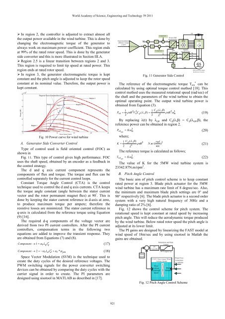
In region 2, the controller is adjusted to extract almost all<br />
the output power available in the wind turbine. This is done by<br />
changing the electromagnetic torque <strong>of</strong> the generator to<br />
always work on maximum power coefficient. This region ends<br />
at 99% <strong>of</strong> the rated rotor speed. This is done by the generator<br />
side converter <strong>and</strong> this is more illustrated in Section III.A.<br />
Region 2.5 is a linear transition between regions 2 <strong>and</strong> 3.<br />
This region is required to limit tip speed at rated power. This<br />
region ends at rated rotor speed.<br />
In region 3, the generator electromagnetic torque is kept<br />
constant <strong>and</strong> the pitch angle is adjusted to keep the rotor speed<br />
constant at its nominal value. There<strong>for</strong>e, the output power is<br />
kept constant.<br />
Fig. 10 Power curve <strong>for</strong> wind turbine<br />
A. Generator Side Converter <strong>Control</strong><br />
Type <strong>of</strong> control used is field oriented control (FOC) as<br />
shown in<br />
Fig. 11. This type <strong>of</strong> control gives high per<strong>for</strong>mance. FOC<br />
uses the shaft speed, obtained by an encoder as a feedback in<br />
the control strategy.<br />
The d <strong>and</strong> q axis current component represents the<br />
components <strong>of</strong> flux <strong>and</strong> torque. The torque <strong>and</strong> flux can be<br />
controlled separately <strong>for</strong> the current control loops.<br />
Constant Torque Angle <strong>Control</strong> (CTA) is the control<br />
technique used to control the d <strong>and</strong> q axis currents. CTA keeps<br />
the torque angle constant (angle between the stator current<br />
vector <strong>and</strong> the rotor permanent magnet flux) at 90 ° . This is<br />
done by keeping the stator current reference in d-axis at zero,<br />
to produce maximum torque per ampere; there<strong>for</strong>e the<br />
resistive losses are minimized. The stator current reference in<br />
q-axis is calculated from the reference torque using Equation<br />
(9) [16].<br />
The required d-q components <strong>of</strong> the voltage vector are<br />
derived from two PI current controllers. After the PI current<br />
controllers, compensation terms in the following two<br />
equations are added to improve the transient response. They<br />
are obtained from Equations (7) <strong>and</strong> (8).<br />
r<br />
Component → 1 = ωrLq<br />
Iq<br />
(17)<br />
r<br />
Component 2 = −ω<br />
rLd Id<br />
+ ωr<br />
* ϕ pm<br />
→ (18)<br />
Space Vector Modulation (SVM) is the technique used to<br />
create the duty cycles <strong>of</strong> the desired reference voltages. The<br />
PWM switching signals <strong>for</strong> the power converter switching<br />
devices can be obtained by comparing the duty cycles with the<br />
carrier signal in order to create. The PI parameters are<br />
designed using sisotool in MATLAB as described in [17].<br />
World Academy <strong>of</strong> Science, Engineering <strong>and</strong> Technology 59 2011<br />
921<br />
Fig. 11 Generator Side <strong>Control</strong><br />
The reference <strong>of</strong> the electromagnetic torque Tem * can be<br />
calculated by using optimal torque control method [18]. This<br />
control method uses the measured rotational speed (rad/sec) <strong>of</strong><br />
the shaft <strong>and</strong> the parameters <strong>of</strong> the wind turbine to obtain the<br />
optimal operating point. The output wind turbine power is<br />
obtained from Equation (3).<br />
1 2 3 1 C p(<br />
λ,<br />
β ) 5 3<br />
Pwt ρπ R VwCp<br />
( λ,<br />
β ) =<br />
ρπR<br />
ω<br />
2<br />
2 3<br />
m<br />
λ<br />
= (19)<br />
By replacing λ(t) by λopt <strong>and</strong> Cp(λ,β) = Cp(λopt,β), the<br />
reference power can be obtained in region 2.<br />
Pwtopt where;<br />
3<br />
Kωm<br />
= (20)<br />
1 C p(<br />
λ,<br />
β ) 5<br />
K = ρπR<br />
2 3<br />
λ<br />
rad 2<br />
N.<br />
m /( )<br />
sec<br />
(21)<br />
The reference torque is calculated as follows;<br />
Twtopt 2<br />
Kωm<br />
= (22)<br />
The value <strong>of</strong> K <strong>for</strong> the 5MW wind turbine system is<br />
23342.87N.m/rpm 2 .<br />
B. Pitch Angle <strong>Control</strong><br />
The basic aim <strong>of</strong> pitch control scheme is to keep constant<br />
rated power at region 3. Blade pitch actuator <strong>for</strong> the 5MW<br />
wind turbine has a maximum rate limit <strong>of</strong> 8 degree/sec. Also,<br />
the minimum <strong>and</strong> maximum blade pitch settings are 0° <strong>and</strong><br />
90° respectively [6]. The blade pitch actuator is a second order<br />
system with a very high natural frequency <strong>of</strong> 30Hz <strong>and</strong> a<br />
damping ratio <strong>of</strong> 2% [6].<br />
Fig. 12 shows the control scheme <strong>for</strong> pitch system. The<br />
rotational speed is kept constant at rated speed by increasing<br />
pitch angle. This will reduce the aerodynamic torque produced<br />
by the wind turbine. Below rated rotor speed the pitch angle is<br />
adjusted at its lower limit.<br />
The PI gains are designed by linearizing the FAST model at<br />
wind speed <strong>of</strong> 18m/sec <strong>and</strong> by using sisotool in Matlab the<br />
gains are obtained.<br />
Fig. 12 Pitch Angle <strong>Control</strong> Scheme