Talk ICCDs
Talk ICCDs
Talk ICCDs

You also want an ePaper? Increase the reach of your titles
YUMPU automatically turns print PDFs into web optimized ePapers that Google loves.
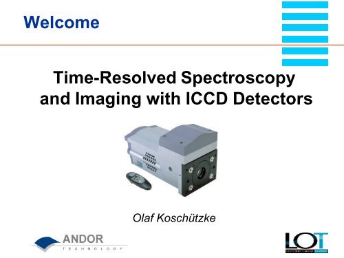
Welcome<br />
Time-Resolved Spectroscopy<br />
and Imaging with ICCD Detectors<br />
Olaf Koschützke
Overview<br />
ICCD and image intensifier design<br />
Parameters and specifications<br />
Applications
Why <strong>ICCDs</strong>?<br />
Image intensifier acts as ultra-fast shutter<br />
Gate widths (= temporal resolution)<br />
as short as 2 ns<br />
Single photon detection
ICCD Design
MCP lmage Intensifier Design<br />
Ultra-fast optical shutter:<br />
ns gating, 50 kHz gate<br />
repetition rates<br />
High vacuum tube<br />
Input window: quartz,<br />
glass, MgF 2, fiber optic<br />
Photocathode<br />
photons → electrons<br />
(photoelectric effect)<br />
-200 V (on), +50 V (off)
MCP lmage Intensifier Design<br />
Micro Channel Plate (MCP):<br />
multiplying of electrons<br />
input 0 V<br />
output +400 V ... +1,000 V<br />
Phosphor screen:<br />
electrons → photons (fluorescence)<br />
+ 6,000 V<br />
Output window:<br />
fiber optic (standard)<br />
glass
MCP (Micro Channel Plate)<br />
Electroding<br />
(on each face)<br />
Lead Silicate<br />
Glass Wafer<br />
Input Events<br />
Channels<br />
(105 - 107 / cm2 )<br />
Output Electrons<br />
Channel diameter: 6 µm (18 mm intensifiers) - 10 µm<br />
(25 mm intensifiers)<br />
VB<br />
-<br />
+
MCP (Micro Channel Plate)<br />
Gain: 1 ... 10,000 el/el (software gain control<br />
0 - 255)<br />
Gain (el/el)<br />
10.000<br />
1.000<br />
100<br />
10<br />
1<br />
400 500 600 700 800 900 1000<br />
MCP Voltage (V)
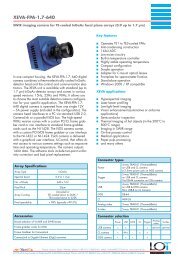
ICCD Specifications<br />
Image intensifier generations<br />
Quantum efficiency of photocathodes<br />
Effective quantum efficiency of image intensifiers<br />
Gating & irising<br />
Phosphor<br />
EBI (Equivalent Background Illumination)
Intensifier Generations<br />
1. Generation<br />
Image intensifiers without MCP<br />
2. Generation<br />
MCP image intensifiers with multi-alkali photocathodes<br />
3. Generation (Filmed)<br />
GaAs photocathodes on glass input windows<br />
Susceptible to ion damage<br />
⇒ ion barrier film (Al 2O 3) on MCP input<br />
⇒ 1) reduces effective QE by ≈ 1/4<br />
2) 800 V photocathode voltage (slower gating)
Intensifier Generations<br />
3. Generation (Filmless)<br />
Gen III image intensifiers without ion barrier film<br />
⇒ improved quantum efficiency up to 50%<br />
Large reduction of poison gases<br />
Lifetime comparable to any filmed Gen III or Gen II<br />
ANDOR was the first to offer 16 bit <strong>ICCDs</strong> with filmless<br />
Gen III image intensifiers
Quantum Efficiency<br />
Input Windows<br />
MgF 2 (120 nm)<br />
Quartz (180 nm)<br />
Glass (270 nm)<br />
Fiber optic (380 nm)
Quantum Efficiency Gen II
Quantum Efficiency Gen II
Quantum Efficiency<br />
Filmless Gen III
Quantum Efficiency<br />
Filmless Gen III<br />
Nd:YAG: 1064 nm
Quantum Efficiency<br />
Filmless Gen III<br />
BGT: VIH photocathode + UV coating of<br />
fiber optic input window of image intensifier
Effective Quantum Efficiency<br />
of Image Intensifiers<br />
Noise Factor<br />
N f : = SNR in / SNR out<br />
N f > 1 for all <strong>ICCDs</strong><br />
Loss mechanisms and<br />
electron multiplication<br />
statistics<br />
Gen II + III: 25% of<br />
photoelectrons lost in<br />
MCP (75% active area)<br />
Detector Noise Factor<br />
Gen II 1.6<br />
Gen III filmless 1.6<br />
Gen III filmed 2.0<br />
CCD 1<br />
EMCCD 1.3
Effective Quantum Efficiency<br />
of Image Intensifers<br />
Filmed Gen III:<br />
additional ≈ 25% photoelectrons<br />
lost in ion barrier film<br />
Effective QE : = Photocathode QE / Noise Factor 2<br />
Very important for fair comparison with CCD and<br />
EMCCD sensitivity!
Gating<br />
Requirement for ns-Gating<br />
High conductivity of photocathode or<br />
Nickel underlayer or<br />
Metal grid:<br />
Advanced Grid<br />
Technology AGT TM<br />
⇒ fast gating,<br />
higher QE
Gating<br />
18 mm Image Intensifiers<br />
Ultra-fast: 2 ns - 5 ns<br />
Fast: 5 ns - 10 ns<br />
Slow (without Nickel underlay): only 50 ns – 100 ns but<br />
up to 40% higher QE<br />
25 mm Image Intensifiers<br />
Ultra-fast: 3 ns<br />
Fast: 7 ns
Irising<br />
Irising<br />
Delay between center<br />
and edge<br />
Irising < 1/3 of specified<br />
minimum optical gate<br />
Measured for each<br />
ICCD
Phosphors<br />
Phosphors are matched to CCD quantum<br />
efficiency<br />
For fast readout, a fast phosphor is required<br />
Phosphor decays are not a simple exponential<br />
Phosphor Decay Time (10%) Relative Light Output<br />
P43 2 ms 100%<br />
P46 200 ns 20%
Resolution<br />
Resolution of Image Intensifers<br />
Depending on channel diameter, MCP design,<br />
electrical field strength, phosphor grain size<br />
18 mm: Gen II 25 µm, Gen III 30 µm<br />
25 mm: 35 µm<br />
Resolution of ICCD Detectors<br />
Depending on intensifier, coupling, CCD pixel size<br />
1.5 to 2 times effective CCD pixel size ⇒ 20 µm – 50 µm<br />
Reduced in lens coupled ICCD
EBI<br />
EBI (Equivalent Background Illumination):<br />
input illuminance required to produce the same output<br />
brightness as thermal electrons<br />
Output Brightness B<br />
2 B0<br />
Background Brightness B0<br />
EBI<br />
B = G I + B0<br />
Input Illumination I
EBI<br />
Dark current of photocathodes<br />
EBI sets lower detection limit<br />
EBI = 0.02 ... 0.1 photoelectrons/pixel/s<br />
Higher for red sensitive photocathodes (lower work<br />
functions)<br />
EBI can be minimized by:<br />
- storing intensifier in darkness (> 1 h)<br />
- cooling the photocathode<br />
(not necessary in a gated application)
EBI<br />
Negligible in gated applications<br />
1 s<br />
10 ms<br />
100 ms<br />
1 ms
Coupling<br />
2 Methods<br />
1) Fiber Optic Coupling<br />
High efficiency (≈ 30%)<br />
⇒ lower gain ⇒ better dynamic range (> 15 bit)
Coupling<br />
Compact<br />
Low optical distortions<br />
2) Lens Coupling<br />
Flexible (convert ICCD to CCD)<br />
No “chicken wire” effect<br />
Low efficiency ⇒ reduced dynamic range<br />
Larger<br />
Optical distortions
Features<br />
Digital Delay Generator (DDG TM ) built into head<br />
Lowest total propagation delay available (35 ns)<br />
Optical gate width as short as 2 ns<br />
Gate repetition rate up to 50 kHz<br />
Wireless remote control<br />
Ultra-compact design
Digital Delay Generator<br />
Built directly into the camera head<br />
Micro components reduce both total propagation delay<br />
and signal jitter (35 ns ± 2 ns)<br />
Programmable gate pulse delay, width, and TTL trigger<br />
output:<br />
0 ns - 25 s<br />
Resolution:<br />
25 ps (gate pulse delay and width)<br />
16 ns (TTL trigger output)
Fine-tune experiment from any location<br />
around optics table (up to a distance of 12 m)<br />
Change remotely:<br />
- Gate pulse width<br />
- Gate pulse delay<br />
- TTL output delay<br />
- MCP gain<br />
1 4<br />
Operate Windows as with<br />
2 3<br />
an ordinary mouse
Ultra-Compact Design<br />
Only a single PCI controller card,<br />
does not require an external controller box<br />
Design eliminates the need for additional bulky<br />
apparatus:<br />
- Saves space<br />
- Enhances performance<br />
- Easy interface to control complete system<br />
Optional power supply for extra cooling to as low as<br />
–15° at 20°C air temperature and –35°C with 10°C water<br />
Optional input/output box with BNC connectors
Applications<br />
Laser Induced Fluorescence (LIF)<br />
Time Resolved Fluorescence (TRF)<br />
Time Resolved Transient Absorption<br />
Time Resolved Resonance Raman<br />
Spectroscopy (TR3)<br />
UV Resonance Raman Spectroscopy<br />
Single Photon Spectroscopy<br />
Single Molecule Detection<br />
Combustion<br />
Butane flame
Applications<br />
Laser Induced Breakdown Spectroscopy<br />
(LIBS)
Applications<br />
1 µs<br />
typical spectrum from<br />
solution of potassium<br />
pertechnetate dissolved in<br />
0.1 mol/l nitric acid<br />
5 µs<br />
atomic emission lines<br />
start to become visible through<br />
the broadened ionic lines
Applications<br />
10 µs<br />
atomic spectral lines dominate,<br />
clear identification of atomic<br />
species is possible
Applications<br />
Laser Induced Plasma Spectroscopy (LIPS)<br />
Pulsed Laser Deposition (PLD)<br />
Laser Ablation
Applications<br />
1 µs<br />
2 µs<br />
3 µs<br />
O 2 (0,24 mbar) Vacuum<br />
20 ns gate width
Applications<br />
Laser Induced Fluorescence (LIF)