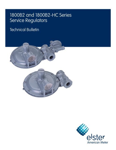
1800B2 and 1800B2-HC Series Service Regulators - Elster-Instromet
1800B2 and 1800B2-HC Series Service Regulators - Elster-Instromet
1800B2 and 1800B2-HC Series Service Regulators - Elster-Instromet

You also want an ePaper? Increase the reach of your titles
YUMPU automatically turns print PDFs into web optimized ePapers that Google loves.
<strong>1800B2</strong> <strong>and</strong> <strong>1800B2</strong>-<strong>HC</strong> <strong>Series</strong><br />
<strong>Service</strong> <strong>Regulators</strong><br />
Technical Bulletin
<strong>1800B2</strong> <strong>and</strong> <strong>1800B2</strong>-<strong>HC</strong> <strong>Series</strong> <strong>Service</strong> <strong>Regulators</strong> 02 <strong>Elster</strong> American Meter<br />
The <strong>1800B2</strong> <strong>Series</strong> pressure regulators are designed to control natural gas,<br />
air, nitrogen, carbon dioxide, propane vapor, <strong>and</strong> other non-corrosive gases<br />
in residential, light commercial, <strong>and</strong> small industrial applications.<br />
General Information<br />
Outlet pressures between 3.5" W.C.<br />
<strong>and</strong> 2 PSIG are available. Operating<br />
temperature range is -20°F to 150°F<br />
(-30°C to 65°C). Maximum flow rate<br />
is 2500 SCFH (70.8 m 3 /h).<br />
All models conform to ANSI Code B109.<br />
4-1998, <strong>and</strong> CGA <strong>Service</strong>-Type Regulator<br />
Specification CAN/CGA-6.18-M95.<br />
Features<br />
• Variety of interchangeable orifices<br />
<strong>and</strong> spring ranges<br />
• 90 Degree (Right Angle), 180 Degree<br />
(Straight-Flow), or Offset Valve Body<br />
(See photo on next page)<br />
• Wide range of valve body<br />
connection sizes<br />
Options<br />
Vent Elbow<br />
The regulator vent opening should face<br />
downward (6 o'clock) to minimize the<br />
chance of blockage from ice <strong>and</strong> snow.<br />
If not possible, a 3/4" NPT plastic, 90˚<br />
vent elbow (part number 78041P025) <strong>and</strong><br />
separate protective screen (part number<br />
70400P017) may be screwed into the vent<br />
to provide the necessary protection.<br />
Elevation Compensation<br />
The E.C. orifice is recommended for<br />
installations where the inlet pressure<br />
may vary over a wide range. The E.C.<br />
orifice is available in two sizes: 1/8" x<br />
3/16" <strong>and</strong> 3/16". The capacities of these<br />
orifices are the same as the st<strong>and</strong>ard<br />
orifice of the same size.<br />
Applications<br />
Model Number Description<br />
1803B2 Basic regulator, non-relieving with 3/4" or 1" NPT vent.<br />
1803B2-<strong>HC</strong> Basic regulator, non-relieving with 3/4" or 1" NPT vent.<br />
1813B2 Basic regulator with full-capacity internal relief with 3/4"<br />
or 1" NPT vent.<br />
1813B2-<strong>HC</strong> Basic regulator with full-capacity internal relief with 3/4"<br />
or 1" NPT vent.<br />
1823B2 Basic regulator, non-relieving with under-pressure shut-off<br />
<strong>and</strong> 3/4" or 1" NPT vent.<br />
1833B2 Basic regulator with full-capacity internal relief <strong>and</strong> underpressure<br />
shut-off <strong>and</strong> 3/4" or 1" NPT vent.<br />
1843B2 Basic regulator with full-capacity internal relief <strong>and</strong> overpressure<br />
shut-off <strong>and</strong> 3/4" or 1" NPT vent.<br />
1843B2-<strong>HC</strong> Basic regulator with full-capacity internal relief <strong>and</strong> overpressure<br />
shut-off <strong>and</strong> 3/4" or 1" NPT vent.<br />
1843B2-L Basic regulator with limited relief <strong>and</strong> overpressure shut-off <strong>and</strong><br />
3/4" or 1" NPT vent.<br />
1853B2 Basic regulator with full-capacity internal relief <strong>and</strong> overpressure,<br />
underpressure shut-off <strong>and</strong> 3/4" or 1" NPT vent.<br />
1883B2 Basic regulator, non-relieving with overpressure shut-off<br />
<strong>and</strong> 3/4" or 1" NPT vent.<br />
1883B2-<strong>HC</strong> Basic regulator, non-relieving with overpressure shut-off<br />
<strong>and</strong> 3/4" or 1" NPT vent.<br />
1893B2 Basic regulator, non-relieving with overpressure, underpressure<br />
shut-off <strong>and</strong> 3/4" or 1" NPT vent.<br />
1853B2 w/USSA Basic regulator with full-capacity internal relief <strong>and</strong> overpressure,<br />
underpressure shut-off <strong>and</strong> 3/4" or 1" NPT vent.<br />
1853B2-<strong>HC</strong> w/USSA Basic regulator with full-capacity internal relief <strong>and</strong> overpressure,<br />
underpressure shut-off <strong>and</strong> 3/4" or 1" NPT vent.<br />
1893B2 w/USSA Basic regulator, non-relieving with overpressure, underpressure<br />
shut-off <strong>and</strong> 3/4" or 1" NPT vent.<br />
1893B2-<strong>HC</strong> w/USSA Basic regulator, non-relieving with overpressure, underpressure<br />
shut-off <strong>and</strong> 3/4" or 1" NPT vent.<br />
Full Capacity Relief Valve<br />
Full capacity relief valve st<strong>and</strong>ard<br />
on some models. (See Performance<br />
Graphs on page 10)<br />
Splashguards<br />
UV stabilized, weather-resistant, resin<br />
device that protects the vent screen from<br />
splashes while providing a large external<br />
vent opening to keep regulators working<br />
properly.<br />
Safety Shutoff Devices<br />
Overpressure Shutoff (OPSO) — Operates<br />
independently. The OPSO will shut off<br />
the gas supply in the event of a serious<br />
downstream pressure build-up. These<br />
are available in two pressure ranges on<br />
the Models 1843B2, 1843B2-<strong>HC</strong>, 1843B-L,<br />
1853B2, 1883B2, 1883B2-<strong>HC</strong>, <strong>and</strong> 1893B2.<br />
Spring Range Part Number<br />
14" W.C. to 35" W.C. 71403P005<br />
1 PSIG to 3 1/2 PSIG 71403P004
<strong>1800B2</strong> <strong>and</strong> <strong>1800B2</strong>-<strong>HC</strong> <strong>Series</strong> <strong>Service</strong> <strong>Regulators</strong> 03 <strong>Elster</strong> American Meter<br />
When the outlet pressure exceeds the<br />
OPSO set point, the pressure under the<br />
OPSO diaphragm plate (A) compresses<br />
the pressure spring (B) forcing the<br />
diaphragm stem (E) upwards <strong>and</strong><br />
releasing plunger (D). This permits the<br />
shut-off spring (F) to force the shut-off<br />
disc (G) against the back side of the<br />
special double-ended orifice.<br />
E<br />
D<br />
C<br />
A OPSO Diaphragm Plate B Pressure Spring<br />
C Cap D Plunger<br />
E Diaphragm Stem F Shut-off Spring<br />
G Shut-off Disc H Adjusting Screw<br />
H<br />
B A<br />
Underpressure Shutoff (UPSO) —<br />
The 1823B2, 1833B2, 1853B2, <strong>and</strong> the<br />
1893B2 regulators come equipped with<br />
an underpressure shutoff (UPSO) device<br />
which utilizes a spring loaded valve stem<br />
<strong>and</strong> o-ring assembly within an orifice<br />
body. It will shut off gas flow through<br />
the regulator in the event of an upstream<br />
underpressure condition.<br />
UPSO in the Open position<br />
Under normal operating conditions,<br />
gas flows through the orifice from<br />
the high pressure upstream to the low<br />
pressure downstream. If conditions<br />
should change to cause the upstream<br />
pressure to decrease, the plunger <strong>and</strong><br />
seat disk assembly will move away<br />
from the orifice thereby opening up<br />
the regulator to compensate for the<br />
lower inlet pressure. The spring in the<br />
Underpressure Shutoff will push the valve<br />
stem assembly up against the face of<br />
the seat disk. Eventually the valve stem’s<br />
o-ring will make contact with the inner<br />
wall of the orifice <strong>and</strong> completely shut<br />
off the gas flow.<br />
F<br />
G<br />
UPSO in the Closed position<br />
When the inlet underpressure condition<br />
has been corrected or repaired, the UPSO<br />
must be manually reset to allow gas flow.<br />
Reset is done by unscrewing the seal<br />
plug <strong>and</strong> pulling up on the diaphragm<br />
stem. This will open the Underpressure<br />
Shutoff <strong>and</strong> allow gas to flow.<br />
A Seal Plug<br />
This type of design allows service<br />
maintenance to be performed to<br />
downstream appliances before<br />
pressure is introduced, i.e. lighting<br />
the pilot light, closing valves, etc.<br />
In some cases downstream failure<br />
may result in the regulator shutting off.<br />
Excessive flow may result in a decrease<br />
in downstream pressure which opens<br />
the seat disk away from the orifice until<br />
the Underpressure Shutoff takes over<br />
<strong>and</strong> shuts the regulator off.<br />
The design has been tested <strong>and</strong> meets<br />
capacity requirements, while insuring<br />
efficient <strong>and</strong> reliable resetting operation<br />
even at sub-zero temperatures.<br />
Capacities of the Underpressure<br />
Shutoff orifice:<br />
A<br />
B Diaphragm Stem<br />
Set Point: 7” W.C.<br />
Inlet Pressure: 20 PSIG<br />
Set at 50 cubic feet per hour<br />
Maximum inlet pressure rating of 60 PSIG<br />
Applicable to ¾”, 1”, <strong>and</strong> 1 ¼” valve bodies<br />
B<br />
Inlet Pressure (PSIG) Flow Rate (SCFH)<br />
3 300<br />
5 400<br />
10 600<br />
15 750<br />
20 900<br />
30 1000<br />
40 1300<br />
60 1500<br />
Universal Safety Shutoff Assembly<br />
(USSA) — USSA protects the downstream<br />
piping from both over- <strong>and</strong> under-pressure<br />
conditions by shutting off the gas flow at<br />
the inlet side of the regulator orifice. Both<br />
Over- <strong>and</strong> under-pressure shut-off set<br />
points are adjustable.<br />
USSA Shutoff Spring Ranges<br />
Over Pressure Spring Ranges<br />
Spring Range Part Number<br />
7.5 - 24“ W.C. 70017P123<br />
20 - 32” W.C. 70017P124<br />
24 - 44” W.C. 70017P125<br />
40 - 84” W.C. 70017P126<br />
3 - 5 PSIG 70017P127<br />
4 - 7 PSIG 70017P128<br />
Under Pressure Spring Ranges<br />
Spring Range Part Number<br />
3 - 6“ W.C. 70017P133<br />
6 - 24” W.C. 70017P134<br />
24 - 60” W.C. 70017P135<br />
Pressure Taps<br />
1/8" NPT taps are available on most<br />
valve heads.<br />
Offset Valve Body
<strong>1800B2</strong> <strong>and</strong> <strong>1800B2</strong>-<strong>HC</strong> <strong>Series</strong> <strong>Service</strong> <strong>Regulators</strong> 04 <strong>Elster</strong> American Meter<br />
2<br />
7 6<br />
Material Specifications<br />
1 Diaphragm Case - Precision die-cast<br />
aluminum with an exclusive seven-<br />
step advanced conversion coating,<br />
single-coat polyester primer <strong>and</strong><br />
high solids polyurethane top coat.<br />
2 Valve Body - Cast grey iron,<br />
undercoated, single coat polyester<br />
primer <strong>and</strong> high solids polyurethane<br />
top coat. NPT threads meet ANSI/<br />
ASME B1.20.1.<br />
Available sizes: 3/4” x 3/4”, 3/4” x 1”,<br />
3/4” x 1-1/4”, 1” x 1”, 1” x 1-1/4” <strong>and</strong><br />
1-1/4” x 1-1/4” NPT or BSP-TR<br />
Offset valve body: 3/4” x 3/4”,<br />
3/4” x 1” <strong>and</strong> 1” x 1” NPT or BSP-TR<br />
3 Pressure Spring - Steel, zinc plated<br />
<strong>and</strong> yellow chromate. Color coded<br />
for identification.<br />
Outlet<br />
Pressure<br />
Color<br />
Code<br />
Part<br />
Number<br />
3.5" to 6" W.C. Blue 70017P043<br />
3.5" to 7.5" W.C. Tan 70017P089<br />
5.5" to 8.5" W.C. Yellow 70017P044<br />
6" to 12" W.C. Brown 70017P137<br />
6" to 15" W.C. Purple 70017P042<br />
12" to 28" W.C. White 70017P060<br />
24" to 48" W.C. Red 70017P082<br />
42" W.C. to 2 PSIG Red - Red 70017P049<br />
10<br />
9<br />
11<br />
4 3<br />
17<br />
Orifice<br />
Size<br />
16<br />
4 Diaphragm Plate - Steel,<br />
Electrogalvanized.<br />
5 Diaphragm - Nylon fabric reinforced<br />
Buna N.<br />
6 Seat Disc - Buna N; 60, 70 (std.)<br />
or 80 durometer rating.<br />
7 Orifice Valve - High strength,<br />
corrosion resistant aluminum.<br />
8<br />
St<strong>and</strong>ard<br />
Part<br />
Number<br />
Part Number<br />
with OPSO<br />
9/16" 72494P026 72751P019<br />
1/2" 72494P025 72751P016<br />
3/8" 72494P023 72751P014<br />
5/16" 72494P022 72751P013<br />
UPSO 71422G004 71422G004<br />
1/4" 72494P021 72751P012<br />
3/16" 72494P020 72751P011<br />
1/8" x 3/16" 72494P030 72751P020<br />
1/8" 72494P019 N/A<br />
8 Lever - Steel, zinc plated <strong>and</strong><br />
yellow chromate.<br />
9 Seal Plug - Minlon.<br />
10 Plunger Guide - Minlon.<br />
11 Pressure Adjustment Screw - Minlon.<br />
5 14<br />
13<br />
12<br />
15<br />
12 Relief Valve Stem - Celcon with<br />
steel, zinc plated <strong>and</strong> yellow<br />
chromate insert.<br />
13 Vent Screen - Stainless Steel -<br />
All models are designed with a<br />
removable weather <strong>and</strong> bug-proof<br />
stainless steel screen to resist<br />
freeze-ups <strong>and</strong> to exclude foreign<br />
matter. The vent is threaded ¾” or<br />
1” NPT (BSP-TR threads available).<br />
A vent line can be added to carry<br />
gas away to a safe outside location<br />
<strong>and</strong> away from any opening(s) in<br />
the building. Comply with applicable<br />
Federal, State, <strong>and</strong> local codes.<br />
14 Vent Valve - Stainless Steel with<br />
Electrogalvanized steel retainer.<br />
15 Relief Valve Spring - Steel, zinc<br />
plated <strong>and</strong> yellow chromate.<br />
Adjustable. Color coded for<br />
identification. St<strong>and</strong>ard set point<br />
of 8” W.C. above outlet set pressure<br />
of 7” W.C. St<strong>and</strong>ard set point of 1.1<br />
PSIG above outlet set pressure of<br />
2 PSIG.<br />
16 Relief Valve Adjustment Nut -<br />
Brass, sintered.<br />
1
<strong>1800B2</strong> <strong>and</strong> <strong>1800B2</strong>-<strong>HC</strong> <strong>Series</strong> <strong>Service</strong> <strong>Regulators</strong> 05 <strong>Elster</strong> American Meter<br />
<strong>1800B2</strong> Regulator Capacity Performance<br />
3/4" Outlet<br />
Set Point 7.0" W.C.<br />
at 50 SCFH<br />
SCFH (m 3 /h) 0.60 specific gravity<br />
gas at 60°F <strong>and</strong> 14.7 PSIA. Pressure<br />
spring 70017P044. Outlet pressure<br />
variance not to exceed +2" -1" W.C.<br />
from set point, horizontal position.<br />
1" Outlet<br />
Set Point 7.0" W.C.<br />
at 50 SCFH<br />
SCFH (m 3 /h) 0.60 specific gravity<br />
gas at 60°F <strong>and</strong> 14.7 PSIA. Pressure<br />
spring 70017P044. Outlet pressure<br />
variance not to exceed +2" -1" W.C.<br />
from set point, horizontal position.<br />
<strong>1800B2</strong> <strong>Series</strong> Regulator Capacity SCFH (m 3 /h)<br />
Inlet<br />
PSIG<br />
(bar)<br />
1<br />
(0.07)<br />
2<br />
(0.14)<br />
3<br />
(0.21)<br />
5<br />
(0.34)<br />
10<br />
(0.70)<br />
15<br />
(1.00)<br />
20<br />
(1.40)<br />
30<br />
(2.10)<br />
40<br />
(2.80)<br />
60<br />
(4.10)<br />
100<br />
(6.90)<br />
125<br />
(8.60)<br />
1/8" x 3/16"<br />
Orifice<br />
—<br />
150<br />
(4.2)<br />
200<br />
(5.7)<br />
250<br />
(7.1)<br />
350<br />
(9.9)<br />
425<br />
(12.0)<br />
500<br />
(14.2)<br />
650<br />
(18.4)<br />
800<br />
(22.7)<br />
1100<br />
(31.2)<br />
1700<br />
(48.1)<br />
2000<br />
(56.6)<br />
3/16"<br />
Orifice<br />
150<br />
(4.2)<br />
225<br />
(6.4)<br />
300<br />
(8.5)<br />
400<br />
(11.3)<br />
600<br />
(17.0)<br />
900<br />
(25.5)<br />
1100<br />
(31.2)<br />
1400<br />
(39.6)<br />
1800<br />
(51.0)<br />
2200<br />
(62.3)<br />
2400<br />
(68.0)<br />
1/4"<br />
Orifice<br />
175<br />
(5.0)<br />
275<br />
(7.8)<br />
375<br />
(10.6)<br />
500<br />
(14.2)<br />
850<br />
(24.1)<br />
1100<br />
(31.2)<br />
1400<br />
(39.6)<br />
1800<br />
(51.0)<br />
2200<br />
(62.3)<br />
2500<br />
(70.8)<br />
2500<br />
(70.8)<br />
5/16"<br />
Orifice<br />
250<br />
(7.1)<br />
375<br />
(10.6)<br />
425<br />
(12.0)<br />
600<br />
(17.0)<br />
1000<br />
(28.3)<br />
1500<br />
(42.5)<br />
1600<br />
(45.3)<br />
2100<br />
(59.5)<br />
2400<br />
(68.0)<br />
2500<br />
(70.8)<br />
3/8"<br />
Orifice<br />
300<br />
(8.5)<br />
400<br />
(11.3)<br />
500<br />
(14.2)<br />
700<br />
(19.8)<br />
1200<br />
(34.0)<br />
1500<br />
(42.5)<br />
1800<br />
(51.0)<br />
2100<br />
(59.5)<br />
2500<br />
(70.8)<br />
1/2"<br />
Orifice<br />
350<br />
(9.9)<br />
475<br />
(13.4)<br />
550<br />
(15.6)<br />
800<br />
(22.7)<br />
1300<br />
(36.8)<br />
1500<br />
(42.5)<br />
1800<br />
(51.0)<br />
2100<br />
(59.5)<br />
9/16"<br />
Orifice<br />
350<br />
(9.9)<br />
475<br />
(13.4)<br />
600<br />
(17.0)<br />
1000<br />
(28.3)<br />
1400<br />
(39.6)<br />
1600<br />
(45.3)<br />
1900<br />
(53.8)<br />
—<br />
— —<br />
— — —<br />
— — — —<br />
— — — — — —<br />
For optimum performance, maximum inlet pressure should not exceed maximum capacity rating for any given<br />
orifice size.<br />
<strong>1800B2</strong> <strong>Series</strong> Regulator Capacity SCFH (m 3 /h)<br />
Inlet<br />
PSIG<br />
(bar)<br />
1<br />
(0.07)<br />
2<br />
(0.14)<br />
3<br />
(0.21)<br />
5<br />
(0.34)<br />
10<br />
(0.70)<br />
15<br />
(1.00)<br />
20<br />
(1.40)<br />
30<br />
(2.10)<br />
40<br />
(2.80)<br />
60<br />
(4.10)<br />
100<br />
(6.90)<br />
125<br />
(8.60)<br />
1/8" x 3/16"<br />
Orifice<br />
—<br />
175<br />
(5.0)<br />
200<br />
(5.7)<br />
275<br />
(7.8)<br />
350<br />
(9.9)<br />
425<br />
(12.0)<br />
500<br />
(14.2)<br />
650<br />
(18.4)<br />
800<br />
(22.7)<br />
1100<br />
(31.2)<br />
1700<br />
(48.1)<br />
2000<br />
(56.6)<br />
3/16"<br />
Orifice<br />
150<br />
(4.2)<br />
250<br />
(7.1)<br />
325<br />
(9.2)<br />
425<br />
(12.0)<br />
650<br />
(18.4)<br />
900<br />
(25.5)<br />
1100<br />
(31.2)<br />
1400<br />
(39.6)<br />
1800<br />
(51.0)<br />
2400<br />
(68.0)<br />
2500<br />
(70.8)<br />
1/4"<br />
Orifice<br />
200<br />
(5.7)<br />
350<br />
(9.9)<br />
400<br />
(11.3)<br />
550<br />
(15.6)<br />
900<br />
(25.5)<br />
1200<br />
(34.0)<br />
1600<br />
(45.3)<br />
2000<br />
(56.6)<br />
2500<br />
(70.8)<br />
2500<br />
(70.8)<br />
2500<br />
(70.8)<br />
5/16"<br />
Orifice<br />
250<br />
(7.1)<br />
375<br />
(10.6)<br />
425<br />
(12.0)<br />
600<br />
(17.0)<br />
1000<br />
(28.3)<br />
1500<br />
(42.5)<br />
1800<br />
(51.0)<br />
2500<br />
(70.8)<br />
2500<br />
(70.8)<br />
2500<br />
(70.8)<br />
3/8"<br />
Orifice<br />
300<br />
(8.5)<br />
400<br />
(11.3)<br />
500<br />
(14.2)<br />
700<br />
(19.8)<br />
1400<br />
(39.6)<br />
1800<br />
(51.0)<br />
2300<br />
(65.1)<br />
2500<br />
(70.8)<br />
2500<br />
(70.8)<br />
2500<br />
(70.8)<br />
1/2"<br />
Orifice<br />
350<br />
(9.9)<br />
475<br />
(13.4)<br />
550<br />
(15.6)<br />
1000<br />
(28.3)<br />
1500<br />
(42.5)<br />
2100<br />
(59.5)<br />
2500<br />
(70.8)<br />
2500<br />
(70.8)<br />
2500<br />
(70.8)<br />
9/16"<br />
Orifice<br />
350<br />
(9.9)<br />
475<br />
(13.4)<br />
600<br />
(17.0)<br />
1000<br />
(28.3)<br />
1800<br />
(51.0)<br />
2400<br />
(68.0)<br />
2500<br />
(70.8)<br />
—<br />
—<br />
— —<br />
— — — —<br />
— — — — — —<br />
For optimum performance, maximum inlet pressure should not exceed maximum capacity rating for any given<br />
orifice size.
<strong>1800B2</strong> <strong>and</strong> <strong>1800B2</strong>-<strong>HC</strong> <strong>Series</strong> <strong>Service</strong> <strong>Regulators</strong> 06 <strong>Elster</strong> American Meter<br />
<strong>1800B2</strong> Regulator Capacity Performance<br />
1-1/4" Outlet<br />
Set Point 7.0" W.C.<br />
at 50 SCFH<br />
SCFH (m 3 /h) 0.60 specific gravity<br />
gas at 60°F <strong>and</strong> 14.7 PSIA. Pressure<br />
spring 70017P044. Outlet pressure<br />
variance not to exceed +2" -1" W.C.<br />
from set point, horizontal position.<br />
3/4" Outlet<br />
Set Point 2 PSIG<br />
at 50 SCFH<br />
SCFH (m 3 /h) 0.60 specific gravity<br />
gas at 60°F <strong>and</strong> 14.7 PSIA. Pressure<br />
spring 70017P049. Outlet pressure<br />
variance not to exceed +/- 10%<br />
from set point, horizontal position.<br />
<strong>1800B2</strong> <strong>Series</strong> Regulator Capacity SCFH (m 3 /h)<br />
Inlet<br />
PSIG<br />
(bar)<br />
1<br />
(0.07)<br />
2<br />
(0.14)<br />
3<br />
(0.21)<br />
5<br />
(0.34)<br />
10<br />
(0.70)<br />
15<br />
(1.00)<br />
20<br />
(1.40)<br />
30<br />
(2.10)<br />
40<br />
(2.80)<br />
60<br />
(4.10)<br />
100<br />
(6.90)<br />
1/8" x 3/16"<br />
Orifice<br />
—<br />
175<br />
(5.0)<br />
225<br />
(6.4)<br />
275<br />
(7.8)<br />
375<br />
(10.6)<br />
450<br />
(12.7)<br />
500<br />
(14.2)<br />
650<br />
(18.4)<br />
800<br />
(22.7)<br />
1100<br />
(31.2)<br />
1700<br />
(48.1)<br />
3/16"<br />
Orifice<br />
150<br />
(4.2)<br />
250<br />
(7.1)<br />
325<br />
(9.2)<br />
475<br />
(13.4)<br />
800<br />
(22.7)<br />
1000<br />
(28.3)<br />
1200<br />
(34.0)<br />
1600<br />
(45.3)<br />
1900<br />
(53.8)<br />
1/4"<br />
Orifice<br />
200<br />
(5.7)<br />
350<br />
(9.9)<br />
475<br />
(13.4)<br />
750<br />
(21.2)<br />
1500<br />
(42.5)<br />
1800<br />
(51.0)<br />
2100<br />
(59.5)<br />
2500<br />
(70.8)<br />
5/16"<br />
Orifice<br />
275<br />
(7.8)<br />
475<br />
(13.4)<br />
550<br />
(15.6)<br />
1000<br />
(28.3)<br />
2200<br />
(62.3)<br />
2500<br />
(70.8)<br />
2500<br />
(70.8)<br />
3/8"<br />
Orifice<br />
350<br />
(9.9)<br />
500<br />
(14.2)<br />
700<br />
(19.8)<br />
1200<br />
(34.0)<br />
2500<br />
(70.8)<br />
2500<br />
(70.8)<br />
2500<br />
(70.8)<br />
1/2"<br />
Orifice<br />
400<br />
(11.3)<br />
650<br />
(18.4)<br />
1000<br />
(28.3)<br />
2000<br />
(56.6)<br />
2500<br />
(70.8)<br />
2500<br />
(70.8)<br />
9/16"<br />
Orifice<br />
400<br />
(11.3)<br />
900<br />
(25.5)<br />
1500<br />
(42.5)<br />
2500<br />
(70.8)<br />
2500<br />
(70.8)<br />
2500<br />
(70.8)<br />
— —<br />
— — — —<br />
— — — — —<br />
— — — — — —<br />
— — — — — —<br />
For optimum performance, maximum inlet pressure should not exceed maximum capacity rating for any given<br />
orifice size.<br />
<strong>1800B2</strong> <strong>Series</strong> Regulator Capacity SCFH (m 3 /h)<br />
Inlet<br />
PSIG<br />
(bar)<br />
3<br />
(0.21)<br />
5<br />
(0.34)<br />
10<br />
(0.70)<br />
15<br />
(1.00)<br />
20<br />
(1.40)<br />
30<br />
(2.10)<br />
40<br />
(2.80)<br />
60<br />
(4.10)<br />
100<br />
(6.90)<br />
125<br />
(8.60)<br />
1/8" x 3/16"<br />
Orifice<br />
—<br />
200<br />
(5.7)<br />
325<br />
(9.2)<br />
425<br />
(12.0)<br />
500<br />
(14.2)<br />
600<br />
(17.0)<br />
750<br />
(21.2)<br />
1100<br />
(31.2)<br />
1600<br />
(45.3)<br />
2000<br />
(56.6)<br />
3/16"<br />
Orifice<br />
200<br />
(5.7)<br />
300<br />
(8.5)<br />
450<br />
(12.7)<br />
600<br />
(17.0)<br />
750<br />
(21.2)<br />
950<br />
(26.9)<br />
1200<br />
(34.0)<br />
1600<br />
(45.3)<br />
2200<br />
(62.3)<br />
1/4"<br />
Orifice<br />
225<br />
(6.4)<br />
375<br />
(10.6)<br />
600<br />
(17.0)<br />
800<br />
(22.7)<br />
1000<br />
(28.3)<br />
1300<br />
(36.8)<br />
1600<br />
(45.3)<br />
2100<br />
(59.5)<br />
2500<br />
(70.8)<br />
5/16"<br />
Orifice<br />
275<br />
(7.8)<br />
475<br />
(13.4)<br />
750<br />
(21.2)<br />
1000<br />
(28.3)<br />
1200<br />
(34.0)<br />
1600<br />
(45.3)<br />
1900<br />
(53.8)<br />
2300<br />
(65.1)<br />
3/8"<br />
Orifice<br />
300<br />
(8.5)<br />
475<br />
(13.4)<br />
800<br />
(22.7)<br />
1000<br />
(28.3)<br />
1300<br />
(36.8)<br />
1700<br />
(48.1)<br />
2100<br />
(59.5)<br />
2500<br />
(70.8)<br />
1/2"<br />
Orifice<br />
375<br />
(10.6)<br />
600<br />
(17.0)<br />
1100<br />
(31.2)<br />
1400<br />
(39.6)<br />
1600<br />
(45.3)<br />
2300<br />
(65.1)<br />
2500<br />
(70.8)<br />
9/16"<br />
Orifice<br />
450<br />
(12.7)<br />
700<br />
(19.8)<br />
1200<br />
(34.0)<br />
1500<br />
(42.5)<br />
1800<br />
(51.0)<br />
—<br />
—<br />
— —<br />
— — — —<br />
— — — — — —<br />
For optimum performance, maximum inlet pressure should not exceed maximum capacity rating for any given<br />
orifice size.
<strong>1800B2</strong> <strong>and</strong> <strong>1800B2</strong>-<strong>HC</strong> <strong>Series</strong> <strong>Service</strong> <strong>Regulators</strong> 07 <strong>Elster</strong> American Meter<br />
<strong>1800B2</strong> Regulator Capacity Performance<br />
1" Outlet<br />
Set Point 2 PSIG<br />
at 50 SCFH<br />
SCFH (m 3 /h) 0.60 specific gravity<br />
gas at 60°F <strong>and</strong> 14.7 PSIA. Pressure<br />
spring 70017P049. Outlet pressure<br />
variance not to exceed +/- 10%<br />
from set point, horizontal position.<br />
1-1/4" Outlet<br />
Set Point 2 PSIG<br />
at 50 SCFH<br />
SCFH (m 3 /h) 0.60 specific gravity<br />
gas at 60°F <strong>and</strong> 14.7 PSIA. Pressure<br />
spring 70017P049. Outlet pressure<br />
variance not to exceed +/- 10%<br />
from set point, horizontal position.<br />
<strong>1800B2</strong> <strong>Series</strong> Regulator Capacity SCFH (m 3 /h)<br />
Inlet<br />
PSIG<br />
(bar)<br />
3<br />
(0.21)<br />
5<br />
(0.34)<br />
10<br />
(0.70)<br />
15<br />
(1.00)<br />
20<br />
(1.40)<br />
30<br />
(2.10)<br />
40<br />
(2.80)<br />
60<br />
(4.10)<br />
100<br />
(6.90)<br />
125<br />
(8.60)<br />
Inlet<br />
PSIG<br />
(bar)<br />
3<br />
(0.21)<br />
5<br />
(0.34)<br />
10<br />
(0.70)<br />
15<br />
(1.00)<br />
20<br />
(1.40)<br />
30<br />
(2.10)<br />
40<br />
(2.80)<br />
60<br />
(4.10)<br />
100<br />
(6.90)<br />
125<br />
(8.60)<br />
1/8" x 3/16"<br />
Orifice<br />
—<br />
200<br />
(5.7)<br />
350<br />
(9.9)<br />
425<br />
(12.0)<br />
500<br />
(14.2)<br />
650<br />
(18.4)<br />
800<br />
(22.7)<br />
1100<br />
(31.2)<br />
1600<br />
(45.3)<br />
2000<br />
(56.6)<br />
1/8" x 3/16"<br />
Orifice<br />
—<br />
200<br />
(5.7)<br />
350<br />
(9.9)<br />
425<br />
(12.0)<br />
500<br />
(14.2)<br />
650<br />
(18.4)<br />
800<br />
(22.7)<br />
1100<br />
(31.2)<br />
1700<br />
(48.1)<br />
2100<br />
(59.5)<br />
3/16"<br />
Orifice<br />
200<br />
(5.7)<br />
300<br />
(8.5)<br />
475<br />
(13.4)<br />
650<br />
(18.4)<br />
800<br />
(22.7)<br />
1000<br />
(28.3)<br />
1300<br />
(36.8)<br />
2100<br />
(59.5)<br />
2500<br />
(70.8)<br />
3/16"<br />
Orifice<br />
200<br />
(5.7)<br />
300<br />
(8.5)<br />
500<br />
(14.2)<br />
650<br />
(18.4)<br />
850<br />
(24.1)<br />
1100<br />
(31.2)<br />
1500<br />
(42.5)<br />
2400<br />
(68.0)<br />
2500<br />
(70.8)<br />
1/4"<br />
Orifice<br />
225<br />
(6.4)<br />
375<br />
(10.6)<br />
600<br />
(17.0)<br />
850<br />
(24.1)<br />
1100<br />
(31.2)<br />
1500<br />
(42.5)<br />
1900<br />
(53.8)<br />
2500<br />
(70.8)<br />
2500<br />
(70.8)<br />
<strong>1800B2</strong> <strong>Series</strong> Regulator Capacity SCFH (m 3 /h)<br />
1/4"<br />
Orifice<br />
225<br />
(6.4)<br />
375<br />
(10.6)<br />
600<br />
(17.0)<br />
850<br />
(24.1)<br />
1100<br />
(31.2)<br />
1600<br />
(45.3)<br />
2200<br />
(62.3)<br />
2500<br />
(70.8)<br />
2500<br />
(70.8)<br />
5/16"<br />
Orifice<br />
275<br />
(7.8)<br />
475<br />
(13.4)<br />
750<br />
(21.2)<br />
1000<br />
(28.3)<br />
1300<br />
(36.8)<br />
1800<br />
(51.0)<br />
2400<br />
(68.0)<br />
2500<br />
(70.8)<br />
5/16"<br />
Orifice<br />
275<br />
(7.8)<br />
475<br />
(13.4)<br />
750<br />
(21.2)<br />
1100<br />
(31.2)<br />
1400<br />
(39.6)<br />
2300<br />
(65.1)<br />
2500<br />
(70.8)<br />
2500<br />
(70.8)<br />
3/8"<br />
Orifice<br />
300<br />
(8.5)<br />
475<br />
(13.4)<br />
850<br />
(24.1)<br />
1100<br />
(31.2)<br />
1400<br />
(39.6)<br />
2000<br />
(56.6)<br />
2500<br />
(70.8)<br />
2500<br />
(70.8)<br />
3/8"<br />
Orifice<br />
300<br />
(8.5)<br />
500<br />
(14.2)<br />
950<br />
(26.9)<br />
1300<br />
(36.8)<br />
1700<br />
(48.1)<br />
2500<br />
(70.8)<br />
2500<br />
(70.8)<br />
2500<br />
(70.8)<br />
1/2"<br />
Orifice<br />
375<br />
(10.6)<br />
600<br />
(17.0)<br />
1200<br />
(34.0)<br />
1500<br />
(42.5)<br />
2000<br />
(56.6)<br />
2500<br />
(70.8)<br />
2500<br />
(70.8)<br />
1/2"<br />
Orifice<br />
375<br />
(10.6)<br />
600<br />
(17.0)<br />
1200<br />
(34.0)<br />
1800<br />
(51.0)<br />
2400<br />
(68.0)<br />
2500<br />
(70.8)<br />
2500<br />
(70.8)<br />
9/16"<br />
Orifice<br />
450<br />
(12.7)<br />
700<br />
(19.8)<br />
1300<br />
(36.8)<br />
1700<br />
(48.1)<br />
2300<br />
(65.1)<br />
9/16"<br />
Orifice<br />
450<br />
(12.7)<br />
750<br />
(21.2)<br />
1400<br />
(39.6)<br />
2100<br />
(59.5)<br />
2500<br />
(70.8)<br />
—<br />
—<br />
— —<br />
— — — —<br />
— — — — — —<br />
For optimum performance, maximum inlet pressure should not exceed maximum capacity rating for any given<br />
orifice size.<br />
—<br />
—<br />
— —<br />
— — — —<br />
— — — — — —<br />
For optimum performance, maximum inlet pressure should not exceed maximum capacity rating for any given<br />
orifice size.
<strong>1800B2</strong> <strong>and</strong> <strong>1800B2</strong>-<strong>HC</strong> <strong>Series</strong> <strong>Service</strong> <strong>Regulators</strong> 08 <strong>Elster</strong> American Meter<br />
<strong>1800B2</strong>-<strong>HC</strong> Regulator<br />
Ideal for light commercial <strong>and</strong> industrial use, the 1-1/4"<br />
<strong>1800B2</strong>-<strong>HC</strong> <strong>Series</strong> regulator is designed to increase output<br />
capacity during medium to high inlet pressure operations.<br />
General Information<br />
The <strong>1800B2</strong>-<strong>HC</strong> <strong>Series</strong> regulator’s<br />
lightweight design features high-capacity<br />
capabilities for 1-1/4" NPT connections<br />
<strong>and</strong> flow capacities up to 4600 SCFH<br />
depending on inlet pressure <strong>and</strong> orifice<br />
selection. It complements the <strong>1800B2</strong><br />
<strong>Series</strong> family of regulators.<br />
<strong>1800B2</strong>-<strong>HC</strong> Regulator Capacity Performance<br />
1-1/4" Outlet<br />
Set Point 7.0" W.C.<br />
at 50 SCFH<br />
SCFH (m 3 /h) 0.60 specific gravity<br />
gas at 60°F <strong>and</strong> 14.7 PSIA. Pressure<br />
spring 70017P044. Outlet pressure<br />
variance not to exceed +2" -1" W.C.<br />
from set point, horizontal position.<br />
AC-630 Meter with 1813B2-<strong>HC</strong> Regulator<br />
<strong>1800B2</strong>-<strong>HC</strong> <strong>Series</strong> Regulator Capacity SCFH (m 3 /h)<br />
Inlet<br />
PSIG<br />
(bar)<br />
1<br />
(0.07)<br />
2<br />
(0.14)<br />
3<br />
(0.21)<br />
5<br />
(0.34)<br />
10<br />
(0.70)<br />
15<br />
(1.00)<br />
20<br />
(1.40)<br />
30<br />
(2.10)<br />
40<br />
(2.80)<br />
60<br />
(4.10)<br />
100<br />
(6.90)<br />
125<br />
(8.60)<br />
1/8" x 3/16"<br />
Orifice<br />
—<br />
150<br />
(4.2)<br />
200<br />
(5.7)<br />
250<br />
(7.1)<br />
350<br />
(9.9)<br />
425<br />
(12.0)<br />
500<br />
(14.2)<br />
650<br />
(18.4)<br />
800<br />
(22.7)<br />
1100<br />
(31.2)<br />
1700<br />
(48.1)<br />
1900<br />
(53.8)<br />
3/16"<br />
Orifice<br />
150<br />
(4.2)<br />
200<br />
(5.7)<br />
250<br />
(7.1)<br />
350<br />
(9.9)<br />
500<br />
(14.2)<br />
600<br />
(17.0)<br />
750<br />
(21.2)<br />
1200<br />
(34.0)<br />
1650<br />
(46.7)<br />
2500<br />
(70.8)<br />
3900<br />
(110.4)<br />
1/4"<br />
Orifice<br />
225<br />
(6.4)<br />
275<br />
(7.8)<br />
350<br />
(9.9)<br />
425<br />
(12.0)<br />
650<br />
(18.4)<br />
900<br />
(25.5)<br />
1000<br />
(28.3)<br />
1700<br />
(48.1)<br />
2600<br />
(73.6)<br />
4500<br />
(127.4)<br />
5/16"<br />
Orifice<br />
225<br />
(6.4)<br />
300<br />
(8.5)<br />
350<br />
(9.9)<br />
500<br />
(14.2)<br />
800<br />
(22.7)<br />
950<br />
(26.9)<br />
2100<br />
(59.4)<br />
3600<br />
(101.9)<br />
4300<br />
(121.7)<br />
4600<br />
(130.2)<br />
3/8"<br />
Orifice<br />
200<br />
(4.2)<br />
350<br />
(9.9)<br />
425<br />
(12.0)<br />
600<br />
(17.0)<br />
800<br />
(22.7)<br />
1500<br />
(42.5)<br />
2200<br />
(62.3)<br />
3000<br />
(84.9)<br />
4100<br />
(116.0)<br />
3900<br />
(110.4)<br />
1/2"<br />
Orifice<br />
325<br />
(9.2)<br />
375<br />
(10.6)<br />
600<br />
(17.0)<br />
750<br />
(21.2)<br />
1500<br />
(42.5)<br />
2200<br />
(62.3)<br />
2700<br />
(76.4)<br />
3900<br />
(110.4)<br />
9/16"<br />
Orifice<br />
300<br />
(8.5)<br />
450<br />
(12.7)<br />
600<br />
(17.0)<br />
850<br />
(24.1)<br />
1700<br />
(48.1)<br />
2300<br />
(65.1)<br />
2900<br />
(82.1)<br />
—<br />
— —<br />
— —<br />
— — — — —<br />
— — — — — —<br />
For optimum performance, maximum inlet pressure should not exceed maximum capacity rating for any given<br />
orifice size.
<strong>1800B2</strong> <strong>and</strong> <strong>1800B2</strong>-<strong>HC</strong> <strong>Series</strong> <strong>Service</strong> <strong>Regulators</strong> 09 <strong>Elster</strong> American Meter<br />
<strong>1800B2</strong> <strong>and</strong> <strong>1800B2</strong>-<strong>HC</strong> <strong>Series</strong> <strong>Service</strong><br />
<strong>Regulators</strong> - Other Technical Data<br />
Full-Open Regulator<br />
Relief Capacity<br />
For sizing downstream relief valves,<br />
use the following formulas to determine<br />
the regulator full-open capacity:<br />
Critical flow rates Sub-critical flows<br />
P1 √P<br />
Q = 0.5 C x Q = C x 2h<br />
√G<br />
√G<br />
Critical flow occurs when the absolute<br />
outlet pressure is less than about 1/2<br />
of the absolute inlet pressure.<br />
Q Maximum capacity of regulator<br />
C Orifice constant (see table below)<br />
P 1<br />
P 2<br />
Inlet absolute pressure (PSIA)<br />
Outlet absolute pressure (PSIA)<br />
h Differential pressure<br />
G Specific gravity of gas<br />
Orifice Constants<br />
Orifice C<br />
1/8" 25<br />
1/8" x 3/16" 25<br />
3/16" 57<br />
1/4" 98<br />
5/16" 149<br />
3/8" 208<br />
1/2" 353<br />
9/16" 421<br />
Maximum Recommended<br />
Inlet Pressure<br />
Orifice Size Inlet Pressure (PSIG)<br />
9/16" 20<br />
1/2" 40<br />
3/8" 100<br />
5/16" 110<br />
1/4" 125<br />
3/16" 125<br />
1/8" x 3/16" 125<br />
1/8" 125<br />
This is the maximum inlet the regulator should operate<br />
at to insure complete lockup at no-flow conditions.<br />
Other Gas Capacities<br />
To determine the capacity of these regulators for gases other than natural gas, multiply<br />
the values within the capacity tables by a Specific Gravity Conversion Factor (Fg). The<br />
table below lists this factor for some of the more common gases.<br />
Gas Type Specific Gravity Conversion Factor (F g)<br />
Air 1.00 0.77<br />
Butane 2.01 0.55<br />
Carbon Dioxide 1.52 0.63<br />
Nitrogen 0.97 0.79<br />
Propane 1.53 0.63<br />
To calculate the Conversion Factor for other gases:<br />
(Fg) = √ Specific gravity of gas on which the capacity table is based<br />
Specific gravity of gas being used<br />
Example: If using propane <strong>and</strong> only having tables based on natural gas,<br />
the Specific Gravity Conversion Factor is:<br />
(Fg) = √ Specific gravity of natural gas (0.6)<br />
Specific gravity of propane (1.53)<br />
(Fg) = √ 0.60<br />
1.53<br />
(Fg) = 0.626<br />
Regulator Pressure Rating<br />
125 PSIG (8.6 bar) = Maximum recommended inlet pressure for normal service.<br />
Maximum recommended pressure may vary with orifice size.<br />
175 PSIG (12 bar) = Maximum inlet pressure for abnormal or emergency service,<br />
without causing damage to regulator case.<br />
2 PSIG (138 mbar) = Maximum outlet pressure for normal service.<br />
10 PSIG (689 mbar) = Maximum outlet pressure which can be contained by pressure<br />
carrying components (no flange leakage to atmosphere except for normal relief action).<br />
If regulator is subjected to these conditions, it should be removed from service.<br />
50 PSIG (3.5 bar) = Maximum outlet pressure for abnormal service without damage to<br />
internal components. If regulator is subjected to these conditions, it should be removed<br />
from service.
<strong>1800B2</strong> <strong>and</strong> <strong>1800B2</strong>-<strong>HC</strong> <strong>Series</strong> <strong>Service</strong> <strong>Regulators</strong> 10 <strong>Elster</strong> American Meter<br />
<strong>1800B2</strong> <strong>and</strong> <strong>1800B2</strong>-<strong>HC</strong> <strong>Service</strong> <strong>Regulators</strong><br />
Regulator Relief Valve Performance<br />
There are several methods of measuring the relief performance of a regulator.<br />
The worst case scenario will occur when the lever is disconnected. The data<br />
presented in the tables below represent this condition.<br />
Outlet Pressure Relative to Inlet Pressure<br />
3/4" Screened Vent – No Vent Pipe Set Pressure 7" W.C.<br />
Outlet Pressure - Inches W.C. (mbar)<br />
90<br />
(224)<br />
80<br />
(199)<br />
70<br />
(174)<br />
60<br />
(149)<br />
50<br />
(124)<br />
40<br />
(100)<br />
30<br />
(75)<br />
20<br />
(50)<br />
10<br />
(25)<br />
9<br />
(.62)<br />
8<br />
(.55)<br />
7<br />
(.48)<br />
6<br />
(.41)<br />
5<br />
(.34)<br />
4<br />
(.26)<br />
3<br />
(.21)<br />
2<br />
(.14)<br />
1<br />
(.07)<br />
0<br />
0 10 20 30 40 50 60 70 80 90 100 110 120 130<br />
(.7) (1.4) (2.1) (2.8) (3.4) (4.1) (4.8) (5.5) (6.2) (6.9) (7.6) (8.3) (9.0)<br />
Inlet Pressure - PSIG (bar)<br />
9/16” 3/8” 1/4” 1/8“ x 3/16”<br />
1/2” 5/16” 3/16”<br />
3/4" Screened Vent – No Vent Pipe Set Pressure 2 PSIG<br />
Outlet Pressure - Inches W.C. (mbar)<br />
0<br />
0 10 20 30 40 50 60 70 80 90 100 110 120 130<br />
(.7) (1.4) (2.1) (2.8) (3.4) (4.1) (4.8) (5.5) (6.2) (6.9) (7.6) (8.3) (9.0)<br />
Inlet Pressure - PSIG (bar)<br />
9/16” 3/8” 1/4” 1/8“ x 3/16”<br />
1/2” 5/16” 3/16”<br />
1" Screened Vent – No Vent Pipe Set Pressure 7" W.C.<br />
Outlet Pressure - Inches W.C. (mbar)<br />
90<br />
(224)<br />
80<br />
(199)<br />
70<br />
(174)<br />
60<br />
(149)<br />
50<br />
(124)<br />
40<br />
(100)<br />
30<br />
(75)<br />
20<br />
(50)<br />
10<br />
(25)<br />
1" Screened Vent – No Vent Pipe Set Pressure 2 PSIG<br />
Outlet Pressure - Inches W.C. (mbar)<br />
9<br />
(.62)<br />
8<br />
(.55)<br />
7<br />
(.48)<br />
6<br />
(.41)<br />
5<br />
(.34)<br />
4<br />
(.26)<br />
3<br />
(.21)<br />
2<br />
(.14)<br />
1<br />
(.07)<br />
0<br />
0 10 20 30 40 50 60 70 80 90 100 110 120 130<br />
(.7) (1.4) (2.1) (2.8) (3.4) (4.1) (4.8) (5.5) (6.2) (6.9) (7.6) (8.3) (9.0)<br />
Inlet Pressure - PSIG (bar)<br />
9/16” 3/8” 1/4” 1/8“ x 3/16”<br />
1/2” 5/16” 3/16”<br />
0<br />
0 10 20 30 40 50 60 70 80 90 100 110 120 130<br />
(.7) (1.4) (2.1) (2.8) (3.4) (4.1) (4.8) (5.5) (6.2) (6.9) (7.6) (8.3) (9.0)<br />
Inlet Pressure - PSIG (bar)<br />
9/16” 3/8” 1/4” 1/8“ x 3/16”<br />
1/2” 5/16” 3/16”
<strong>1800B2</strong> <strong>and</strong> <strong>1800B2</strong>-<strong>HC</strong> <strong>Series</strong> <strong>Service</strong> <strong>Regulators</strong> 11 <strong>Elster</strong> American Meter<br />
1843B2-L Regulator with Limited Relief<br />
The 1843B2-L has a limited relief feature that reduces<br />
the amount of gas released to the atmosphere.<br />
General Information<br />
Limited Relief is accomplished by<br />
installing a relief restriction cup inside<br />
the diaphragm assembly of the 1843B2<br />
regulator. The 1843B2-L regulator utilizes<br />
overpressure protection as part of its<br />
assembly, which will shut off the gas<br />
in the event of over pressure condition.<br />
Full Relief Diaphragm Assembly<br />
Limited Relief Diaphragm Assembly<br />
Under regulator lockup conditions, an<br />
increase in gas temperature or very small<br />
gas leakage through the orifice can raise<br />
the outlet gas pressure. The limited relief<br />
will release this small increase in outlet<br />
pressure to atmosphere without the OPSO<br />
tripping. But should the outlet pressure<br />
continue to increase for some reason,<br />
then the OPSO will shut off <strong>and</strong> close<br />
off the gas flow.<br />
3/8" O/D minimum pipe size is<br />
recommended should the relief<br />
connection require piping to a safe<br />
location. Care must be taken to prevent<br />
water from closing off or entering into<br />
the vent opening. Any kind of blockage<br />
of the vent or vent pipe must be prevented.<br />
To the right is a graphical representation<br />
of the difference of gas flow between<br />
a st<strong>and</strong>ard relief valve <strong>and</strong> a limited<br />
relief valve.<br />
Flow Through Vent<br />
Flow (SCFH)<br />
Flow (SCFH)<br />
3000<br />
2750<br />
2500<br />
2250<br />
2000<br />
1750<br />
1500<br />
1250<br />
1000<br />
750<br />
500<br />
250<br />
1400<br />
1200<br />
1000<br />
0<br />
0.5 0.7 0.9 1 1.1 1.2 1.4 1.5 1.6 2 2.5 3 3.5 4 4.5 5 5.5 6 6.4 6.5<br />
Outlet (PSIG)<br />
800<br />
600<br />
400<br />
200<br />
Limited Relief St<strong>and</strong>ard IRV<br />
Flow Through Vent - Enlarged View of Tinted Area<br />
0<br />
0.5 0.7 0.9<br />
Outlet (PSIG)<br />
1 1.1<br />
Limited Relief St<strong>and</strong>ard IRV
<strong>1800B2</strong> <strong>and</strong> <strong>1800B2</strong>-<strong>HC</strong> <strong>Series</strong> <strong>Service</strong> <strong>Regulators</strong> 12 <strong>Elster</strong> American Meter<br />
<strong>1800B2</strong> <strong>and</strong> <strong>1800B2</strong>-<strong>HC</strong> <strong>Series</strong><br />
<strong>Service</strong> Regulator Dimensions<br />
Model 1803B2, 1803B2-<strong>HC</strong>, 1813B2 <strong>and</strong> 1813B2-<strong>HC</strong> 90°<br />
Model 1803B2, 1803B2-<strong>HC</strong>, 1813B2 <strong>and</strong> 1813B2-<strong>HC</strong> 90°<br />
C<br />
F<br />
C<br />
F<br />
Model D1803B2,<br />
1803B2-<strong>HC</strong>, 1813B2 <strong>and</strong> 1813B2-<strong>HC</strong> 90°<br />
D<br />
E<br />
E<br />
D<br />
A<br />
A<br />
B<br />
Model 1803B2, 1803B2-<strong>HC</strong>, 1813B2 <strong>and</strong> 1813B2-<strong>HC</strong> 180°<br />
Model 1803B2, 1803B2-<strong>HC</strong>, 1813B2 <strong>and</strong><br />
C<br />
1813B2-<strong>HC</strong> 180°<br />
F<br />
C<br />
F<br />
Model 1803B2, D 1803B2-<strong>HC</strong>, 1813B2 <strong>and</strong> 1813B2-<strong>HC</strong> 180°<br />
D<br />
D<br />
E<br />
D<br />
D<br />
E<br />
E<br />
D<br />
E<br />
E<br />
E<br />
D<br />
E<br />
A<br />
A<br />
A<br />
A<br />
B<br />
Model 1803B2 <strong>and</strong> 1813B2 - Offset<br />
Model 1803B2 <strong>and</strong> 1813B2<br />
C<br />
- Offset<br />
F<br />
C<br />
F<br />
Model 1803B2 <strong>and</strong> 1813B2 - Offset<br />
A<br />
A<br />
A<br />
Model 1823B2 <strong>and</strong> 1833B2 - 90°<br />
Model 1823B2 <strong>and</strong> 1833B2 - 90°<br />
C<br />
C F<br />
F<br />
Model 1823B2 <strong>and</strong> 1833B2 - 90°<br />
B<br />
B<br />
B<br />
B<br />
B<br />
B<br />
B<br />
C<br />
C<br />
C<br />
C<br />
F<br />
F<br />
F<br />
Model 1803B2, 1803B2-<strong>HC</strong>, 1813B2, <strong>and</strong> 1813B2-<strong>HC</strong> - 90°<br />
Inlet Outlet A B C Model 1823B2 D <strong>and</strong> 1833B2 E - 180° F<br />
3/4"<br />
3/4"<br />
3/4"<br />
1"<br />
1-9/16"<br />
39.7mm<br />
1-9/16"<br />
8-7/8"<br />
225.4mm<br />
8-7/8"<br />
D7-1/4"<br />
D184.2mm<br />
7-1/4"<br />
4-1/8"<br />
104.8mm<br />
4-1/8"<br />
2"<br />
50.8mm C<br />
2"<br />
F<br />
3-5/8"<br />
92.1mm<br />
3-5/8"<br />
39.7mm 225.4mm 184.2mm 104.8mm 50.8mm 92.1mm<br />
1" 1" 1-9/16"<br />
39.7mm<br />
8-7/8"<br />
225.4mm<br />
E 7-1/4"<br />
184.2mm<br />
ED<br />
A<br />
7-1/4"<br />
E 184.2mm<br />
ED<br />
7-1/4"<br />
184.2mm<br />
7-1/4" A<br />
184.2mm A<br />
7-1/4"<br />
E<br />
184.2mm<br />
Model 1823B2 <strong>and</strong> 1833B2 - 180°<br />
Model 1823B2 <strong>and</strong> 1833B2<br />
C<br />
- 180°<br />
C F<br />
F<br />
4-1/8"<br />
104.8mm<br />
2"<br />
50.8mm<br />
Model A 1823B2 <strong>and</strong> 1833B2 B - Offset<br />
Model 1823B2 <strong>and</strong> 1833B2 C - Offset<br />
F<br />
C<br />
F<br />
Model 1803B2, 1803B2-<strong>HC</strong>, 1813B2, <strong>and</strong> 1813B2-<strong>HC</strong> - 180°<br />
3-5/8"<br />
92.1mm<br />
Inlet Outlet A B D<br />
Model 1823B2 <strong>and</strong> 1833B2 - Offset<br />
C D E F<br />
3/4" 3/4" 1"<br />
25.4mm<br />
8-7/8"<br />
225.4mm<br />
D 7-1/4"<br />
184.2mm<br />
4-1/8"<br />
104.8mm<br />
C<br />
2"<br />
50.8mm<br />
F<br />
3-5/8"<br />
92.1mm<br />
3/4" 1" 1"<br />
25.4mm<br />
1" 1" 1"<br />
25.4mm<br />
1" 1-1/4" 1-1/8"<br />
28.6mm<br />
1-1/4" 1-1/4" 1-1/8"<br />
28.6mm<br />
3/4" 1-1/4" 1-1/8"<br />
28.6mm<br />
8-7/8"<br />
225.4mm<br />
8-7/8"<br />
225.4mm<br />
8-7/8"<br />
225.4mm<br />
8-7/8"<br />
225.4mm<br />
Model 1803B2 <strong>and</strong> 1813B2 - Offset<br />
8-7/8" 7-1/4" 4-1/8" 2" 3-5/8"<br />
225.4mm Model 184.2mm 1843B2, 1843B2-<strong>HC</strong>, 104.8mm 1883B2 50.8mm <strong>and</strong> 1883B2-<strong>HC</strong> 92.1mm<br />
A<br />
B<br />
Model 1843B2, 1843B2-<strong>HC</strong>, 1883B2 <strong>and</strong> 1883B2-<strong>HC</strong><br />
D<br />
D<br />
4-1/8"<br />
104.8mm<br />
4-1/8"<br />
104.8mm<br />
4-1/8"<br />
104.8mm<br />
4-1/8"<br />
104.8mm<br />
Model 1853B2 <strong>and</strong> B 1893B2<br />
B<br />
2"<br />
50.8mm<br />
2"<br />
50.8mm<br />
B 2"<br />
B 50.8mm<br />
2"<br />
50.8mm<br />
Model 1853B2 <strong>and</strong> 1893B2<br />
C<br />
F<br />
C<br />
F<br />
3-5/8"<br />
92.1mm<br />
3-5/8"<br />
92.1mm<br />
3-5/8"<br />
92.1mm<br />
3-5/8"<br />
92.1mm<br />
D<br />
C<br />
Inlet Outlet A B C D E F F<br />
3/4" 3/4" 1"<br />
E<br />
8-7/8" 7-1/4" 4-1/8" 2" 3-5/8"<br />
3/4" 1"<br />
25.4mm<br />
1"<br />
E225.4mm<br />
D<br />
8-7/8"<br />
184.2mm<br />
A<br />
7-1/4"<br />
104.8mm<br />
4-1/8"<br />
50.8mm<br />
B<br />
2"<br />
92.1mm<br />
3-5/8"<br />
25.4mm 225.4mm A 184.2mm 104.8mm B 50.8mm 92.1mm<br />
1" 1" 1"<br />
25.4mm<br />
8-7/8"<br />
225.4mm E<br />
D<br />
E<br />
A<br />
C<br />
C F<br />
Model 1843B2, 1843B2-<strong>HC</strong>, 1883B2 <strong>and</strong> 1883B2-<strong>HC</strong> F<br />
A<br />
7-1/4"<br />
184.2mm<br />
4-1/8"<br />
104.8mm<br />
B<br />
2"<br />
50.8mm<br />
Model 1853B2 <strong>and</strong> 1893B2<br />
C<br />
F<br />
3-5/8"<br />
92.1mm
<strong>1800B2</strong> <strong>and</strong> <strong>1800B2</strong>-<strong>HC</strong> <strong>Series</strong> <strong>Service</strong> <strong>Regulators</strong> 13 <strong>Elster</strong> American Meter<br />
E<br />
B<br />
<strong>1800B2</strong> <strong>and</strong> <strong>1800B2</strong>-<strong>HC</strong> <strong>Series</strong><br />
<strong>Service</strong> Regulator Dimensions<br />
D<br />
E<br />
D<br />
D<br />
E<br />
E<br />
D<br />
D<br />
E<br />
E<br />
Model 1823B2 <strong>and</strong> 1833B2 - 90°<br />
A<br />
Model 1823B2 <strong>and</strong> 1833B2 - 180°<br />
A<br />
Model 1823B2 <strong>and</strong> 1833B2 - Offset<br />
A<br />
A<br />
Model 1823B2 <strong>and</strong> 1833B2 - 180°<br />
A<br />
Model 1823B2 <strong>and</strong> 1833B2 - Offset<br />
A<br />
B<br />
Model 1843B2, 1843B2-<strong>HC</strong>, 1883B2 <strong>and</strong> 1883B2-<strong>HC</strong><br />
C<br />
Model 1843B2, 1843B2-<strong>HC</strong>, 1883B2 <strong>and</strong> 1883B2-<strong>HC</strong><br />
F<br />
B<br />
B<br />
B<br />
B<br />
C<br />
C<br />
C<br />
C<br />
C<br />
F<br />
F<br />
F<br />
F<br />
F<br />
Model 1823B2 <strong>and</strong> 1833B2 - 90°<br />
Inlet Outlet A<br />
D<br />
B C D E F<br />
3/4" 3/4" 1-9/16" 8-7/8" 7-1/4" 5-1/8" 2" 3-5/8"<br />
39.7mm 225.4mm 184.2mm 130.2mm 50.8mm 92.1mm<br />
3/4" 1" 1-9/16"<br />
39.7mm<br />
1" 1" 1-9/16"<br />
39.7mm<br />
Model 1823B2 <strong>and</strong> 1833B2 - 180°<br />
Inlet Outlet A B C D E F<br />
3/4" 3/4" 1"<br />
25.4mm<br />
3/4" 1" 1"<br />
25.4mm<br />
1" 1" 1"<br />
25.4mm<br />
1" 1-1/4" 1-1/8"<br />
28.6mm<br />
1-1/4" 1-1/4" 1-1/8"<br />
28.6mm<br />
3/4" 1-1/4" 1-1/8"<br />
28.6mm<br />
8-7/8"<br />
225.4mm<br />
8-7/8"<br />
225.4mm<br />
8-7/8"<br />
225.4mm<br />
8-7/8"<br />
225.4mm<br />
8-7/8"<br />
225.4mm<br />
8-7/8"<br />
225.4mm<br />
Model 1823B2 <strong>and</strong> 1833B2 - Offset<br />
7-1/4"<br />
184.2mm<br />
7-1/4"<br />
184.2mm<br />
7-1/4"<br />
184.2mm<br />
7-1/4"<br />
184.2mm<br />
7-1/4"<br />
184.2mm<br />
7-1/4"<br />
184.2mm<br />
5-1/8"<br />
130.2mm<br />
5-1/8"<br />
130.2mm<br />
5-1/8"<br />
130.2mm<br />
5-1/8"<br />
130.2mm<br />
5-1/8"<br />
130.2mm<br />
5-1/8"<br />
130.2mm<br />
2"<br />
50.8mm<br />
2"<br />
50.8mm<br />
2"<br />
50.8mm<br />
2"<br />
50.8mm<br />
2"<br />
50.8mm<br />
2"<br />
50.8mm<br />
3-5/8"<br />
92.1mm<br />
3-5/8"<br />
92.1mm<br />
3-5/8"<br />
92.1mm<br />
3-5/8"<br />
92.1mm<br />
3-5/8"<br />
92.1mm<br />
3-5/8"<br />
92.1mm<br />
Inlet Outlet A B C D E F<br />
3/4" 3/4" 1"<br />
25.4mm<br />
3/4" 1" 1"<br />
25.4mm<br />
1" 1" 1"<br />
25.4mm<br />
D<br />
E<br />
8-7/8"<br />
225.4mm<br />
E<br />
8-7/8"<br />
225.4mm<br />
8-7/8"<br />
225.4mm<br />
8-7/8"<br />
225.4mm<br />
8-7/8"<br />
225.4mm<br />
A<br />
7-1/4"<br />
184.2mm<br />
7-1/4"<br />
184.2mm<br />
A<br />
7-1/4"<br />
184.2mm<br />
7-1/4"<br />
184.2mm<br />
7-1/4"<br />
184.2mm<br />
Model 1853B2 <strong>and</strong> 1893B2<br />
5-1/8"<br />
130.2mm<br />
5-1/8"<br />
130.2mm<br />
5-1/8"<br />
130.2mm<br />
5-1/8"<br />
130.2mm<br />
5-1/8"<br />
130.2mm<br />
B<br />
C<br />
2"<br />
50.8mm<br />
2"<br />
50.8mm<br />
B<br />
2"<br />
50.8mm<br />
2"<br />
50.8mm<br />
2"<br />
50.8mm<br />
F<br />
3-5/8"<br />
92.1mm<br />
3-5/8"<br />
92.1mm<br />
3-5/8"<br />
92.1mm<br />
3-5/8"<br />
92.1mm<br />
3-5/8"<br />
92.1mm
F<br />
E<br />
<strong>1800B2</strong> <strong>and</strong> <strong>1800B2</strong>-<strong>HC</strong> <strong>Series</strong><br />
D A<br />
B<br />
<strong>Service</strong> Regulator Dimensions<br />
D<br />
E<br />
D<br />
E<br />
D<br />
E<br />
Model 1843B2, 1843B2-<strong>HC</strong>, 1883B2 <strong>and</strong> 1883B2-<strong>HC</strong><br />
A<br />
A<br />
A<br />
Model 1823B2 <strong>and</strong> 1833B2 - Offset<br />
Model 1843B2, 1843B2-<strong>HC</strong>, 1883B2 <strong>and</strong> 1883B2-<strong>HC</strong><br />
Model 1853B2 <strong>and</strong> 1893B2<br />
B<br />
C<br />
B C<br />
Model 1853B2 <strong>and</strong> 1893B2<br />
B<br />
<strong>1800B2</strong> <strong>and</strong> <strong>1800B2</strong>-<strong>HC</strong> <strong>Series</strong> <strong>Service</strong> <strong>Regulators</strong> 14 <strong>Elster</strong> American Meter<br />
D<br />
E<br />
D<br />
E<br />
A<br />
A<br />
A<br />
B<br />
B<br />
B<br />
C<br />
C<br />
C<br />
F<br />
F<br />
F<br />
F<br />
F<br />
Model 1843B2, 1843B2-<strong>HC</strong>, 1883B2 <strong>and</strong> 1883B2-<strong>HC</strong><br />
Inlet Outlet A B C D E F<br />
3/4" 3/4" 4-1/2"<br />
114.3mm<br />
3/4" 1" 4-1/2"<br />
114.3mm<br />
1" 1" 4-1/2"<br />
114.3mm<br />
1" 1-1/4" 4-1/2"<br />
114.3mm<br />
1-1/4" 1-1/4" 4-1/2"<br />
114.3mm<br />
Model 1853B2 <strong>and</strong> 1893B2<br />
Inlet Outlet A B C D E F<br />
3/4" 3/4" 4-1/2"<br />
114.3mm<br />
3/4" 1" 4-1/2"<br />
114.3mm<br />
1" 1" 4-1/2"<br />
114.3mm<br />
1" 1-1/4" 4-1/2"<br />
114.3mm<br />
1-1/4" 1-1/4" 4-1/2"<br />
114.3mm<br />
8-15/16"<br />
227.0mm<br />
8-15/16"<br />
227.0mm<br />
8-15/16"<br />
227.0mm<br />
8-15/16"<br />
227.0mm<br />
8-15/16"<br />
227.0mm<br />
8-15/16"<br />
227.0mm<br />
8-15/16"<br />
227.0mm<br />
8-15/16"<br />
227.0mm<br />
8-15/16"<br />
227.0mm<br />
8-15/16"<br />
227.0mm<br />
7-1/4"<br />
184.2mm<br />
7-1/4"<br />
184.2mm<br />
7-1/4"<br />
184.2mm<br />
7-1/4"<br />
184.2mm<br />
7-1/4"<br />
184.2mm<br />
7-1/4"<br />
184.2mm<br />
7-1/4"<br />
184.2mm<br />
7-1/4"<br />
184.2mm<br />
7-1/4"<br />
184.2mm<br />
7-1/4"<br />
184.2mm<br />
4-1/8"<br />
104.8mm<br />
4-1/8"<br />
104.8mm<br />
4-1/8"<br />
104.8mm<br />
4-1/8"<br />
104.8mm<br />
4-1/8"<br />
104.8mm<br />
5-1/8"<br />
130.2mm<br />
5-1/8"<br />
130.2mm<br />
5-1/8"<br />
130.2mm<br />
5-1/8"<br />
130.2mm<br />
5-1/8"<br />
130.2mm<br />
2"<br />
50.8mm<br />
2"<br />
50.8mm<br />
2"<br />
50.8mm<br />
2"<br />
50.8mm<br />
2"<br />
50.8mm<br />
2"<br />
50.8mm<br />
2"<br />
50.8mm<br />
2"<br />
50.8mm<br />
2"<br />
50.8mm<br />
2"<br />
50.8mm<br />
3-5/8"<br />
92.1mm<br />
3-5/8"<br />
92.1mm<br />
3-5/8"<br />
92.1mm<br />
3-5/8"<br />
92.1mm<br />
3-5/8"<br />
92.1mm<br />
3-5/8"<br />
92.1mm<br />
3-5/8"<br />
92.1mm<br />
3-5/8"<br />
92.1mm<br />
3-5/8"<br />
92.1mm<br />
3-5/8"<br />
92.1mm
<strong>1800B2</strong> <strong>and</strong> <strong>1800B2</strong>-<strong>HC</strong> <strong>Series</strong> <strong>Service</strong> <strong>Regulators</strong> 15 <strong>Elster</strong> American Meter<br />
Regulator Assembly Positions<br />
180° Models<br />
Valve Head Position "A"<br />
1<br />
2<br />
4<br />
3<br />
St<strong>and</strong>ard<br />
Vent Position<br />
Valve Head Position "C"<br />
3<br />
4<br />
2<br />
1<br />
St<strong>and</strong>ard<br />
Vent Position<br />
90° Models<br />
Valve Head Position "A"<br />
Offset Models<br />
Valve Head Position "D"<br />
4<br />
1<br />
3<br />
1<br />
2<br />
4<br />
2<br />
St<strong>and</strong>ard<br />
Vent Position<br />
Valve Head Position "C"<br />
1<br />
2<br />
4<br />
3<br />
3<br />
St<strong>and</strong>ard<br />
Vent Position<br />
St<strong>and</strong>ard<br />
Vent Position<br />
Valve Head Position "B"<br />
1<br />
2<br />
4<br />
3<br />
St<strong>and</strong>ard<br />
Vent Position<br />
Valve Head Position "D"<br />
3<br />
1<br />
2<br />
4<br />
St<strong>and</strong>ard<br />
Vent Position<br />
Valve Head Position "B"<br />
4<br />
2<br />
1<br />
3<br />
St<strong>and</strong>ard<br />
Vent Position<br />
Valve Head Position "D"<br />
1<br />
2<br />
4<br />
3<br />
VENT<br />
St<strong>and</strong>ard<br />
Vent Position<br />
AC-250 Meter with 1813B2 Regulator<br />
Example of Regulator<br />
Assembly Position<br />
In the photo above the 1813B2 Regulator<br />
shown has an 180 degree valve head in<br />
Position "C" (Flow upward) with the vent in<br />
position 2 (Looking down). This would be<br />
assembly position C2.<br />
Ordering Information<br />
1 Model number<br />
2 Size of inlet <strong>and</strong> outlet<br />
3 Inlet pressure, PSIG (bar)<br />
4 Outlet pressure, inches W.C.<br />
(mbar) or PSIG (bar)<br />
5 Flow, SCFH (m3/h)<br />
6 Kind <strong>and</strong> specific gravity of gas<br />
7 Orifice size<br />
8 Regulator assembly position<br />
number<br />
9 Possible variation in inlet pressure<br />
for E.C. Orifice models<br />
Maximum ___ PSIG (bar)<br />
Minimum ___ PSIG (bar)<br />
Shipping Weight<br />
17.5 lbs/carton of four regulators
About <strong>Elster</strong> Group<br />
A world leader in advanced metering<br />
infrastructure, integrated metering, <strong>and</strong><br />
utilization solutions to the gas, electricity<br />
<strong>and</strong> water industries, <strong>Elster</strong>’s systems<br />
<strong>and</strong> solutions reflect over 170 years of<br />
knowledge <strong>and</strong> experience in measuring<br />
precious resources <strong>and</strong> energy.<br />
<strong>Elster</strong> provides solutions <strong>and</strong> advanced<br />
technologies to help utilities more easily,<br />
efficiently <strong>and</strong> reliably obtain <strong>and</strong> use<br />
advanced metering intelligence to<br />
improve customer service, enhance<br />
operational efficiency, <strong>and</strong> increase<br />
revenues. <strong>Elster</strong>'s AMI solutions enable<br />
utilities to cost-effectively generate, deliver,<br />
manage, <strong>and</strong> conserve the life-essential<br />
resources of gas, electricity, <strong>and</strong> water.<br />
<strong>Elster</strong> has over 7500 staff <strong>and</strong><br />
operations in 38 countries in North<br />
<strong>and</strong> South America, Europe, <strong>and</strong> Asia.<br />
<strong>Elster</strong> American Meter<br />
2221 Industrial Road<br />
Nebraska City, NE 68410<br />
USA<br />
T +1 402 873 8200<br />
F +1 402 873 7616<br />
www.elster-americanmeter.com<br />
<strong>Elster</strong> Canadian Meter<br />
275 Industrial Road<br />
Cambridge, Ontario<br />
N3H 4R7<br />
Canada<br />
T +1 519 650 1900<br />
F +1 519 650 1917<br />
www.elster-canadianmeter.com<br />
© 2008 <strong>Elster</strong> American Meter. All rights reserved.<br />
Information contained herein is subject to change<br />
without notice. Product specifications may change.<br />
Contact your <strong>Elster</strong> American Meter representative<br />
for the most current product information. Printed in<br />
the United States.<br />
EAM-TB8510.8-EN-P - April 2008<br />
Supersedes SB 8510.7, TDB-8620.2 <strong>and</strong> TDB-8622.1