Download PDF - GSW Water Heating
Download PDF - GSW Water Heating
Download PDF - GSW Water Heating

Create successful ePaper yourself
Turn your PDF publications into a flip-book with our unique Google optimized e-Paper software.
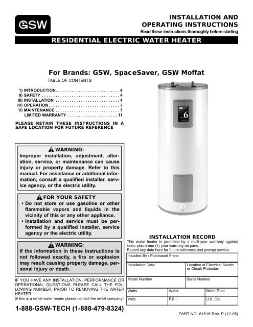
INSTALLATION AND<br />
OPERATING INSTRUCTIONS<br />
Read these instructions thoroughly before starting<br />
RESIDENTIAL ELECTRIC WATER HEATER<br />
For Brands: <strong>GSW</strong>, SpaceSaver, <strong>GSW</strong> Moffat<br />
TABLE OF CONTENTS<br />
1) INTRODUCTION. . . . . . . . . . . . . . . . . . . . . . . . . . . . 4<br />
II) SAFETY . . . . . . . . . . . . . . . . . . . . . . . . . . . . . . . . . . 4<br />
III) INSTALLATION . . . . . . . . . . . . . . . . . . . . . . . . . . . . 4<br />
IV) OPERATION . . . . . . . . . . . . . . . . . . . . . . . . . . . . . . . 7<br />
V) MAINTENANCE . . . . . . . . . . . . . . . . . . . . . . . . . . . . 7<br />
LIMITED WARRANTY . . . . . . . . . . . . . . . . . . . . . . 11<br />
PLEASE RETAIN THESE INSTRUCTIONS IN A<br />
SAFE LOCATION FOR FUTURE REFERENCE<br />
WARNING:<br />
Improper installation, adjustment, alteration,<br />
service, or maintenance can cause<br />
injury or property damage. Refer to this<br />
manual. For assistance or additional information,<br />
consult a qualified installer, service<br />
agency, or the electric utility.<br />
FOR YOUR SAFETY<br />
• Do not store or use gasoline or other<br />
flammable vapors and liquids in the<br />
vicinity of this or any other appliance.<br />
• Installation and service must be performed<br />
by a qualified installer, service<br />
agency or the electric utility.<br />
WARNING:<br />
If the information in these instructions is<br />
not followed exactly, a fire or explosion<br />
may result causing property damage, personal<br />
injury or death.<br />
IF YOU HAVE ANY INSTALLATION, PERFORMANCE OR<br />
OPERATIONAL QUESTIONS PLEASE CALL THE FOL-<br />
LOWING NUMBER, PRIOR TO REMOVING THE WATER<br />
HEATER<br />
(if this is a rental water heater please contact the rental company)<br />
1-888-<strong>GSW</strong>-TECH (1-888-479-8324)<br />
INSTALLATION RECORD<br />
This water heater is protected by a multi-year warranty against<br />
leaks plus a one (1) year warranty on parts.<br />
Record key data here for future reference and prompt service:<br />
Installed By / Purchased From:<br />
Installation Date:<br />
Model Number<br />
Location of Electrical Switch<br />
or Circuit Protector:<br />
Serial Number<br />
Watts Watts Watts-Total<br />
Volts P.S.I. U.S. Gal.<br />
PART NO. 61515 Rev. P (12-05)
This page intentionally left blank. May be used for notes or to record other installation information.<br />
– 2 –
This page intentionally left blank. May be used for notes or to record other installation information.<br />
– 3 –
1) INTRODUCTION<br />
Thank you for purchasing this water heater. Properly<br />
installed and maintained, it will provide years of trouble free<br />
service.<br />
The warranty on this water heater is in effect only when the<br />
water heater is installed and operated in accordance with<br />
these instructions. The manufacturer of this water heater<br />
will not be liable for any injury or property damage resulting<br />
from failure to comply with these instructions.<br />
IMPORTANT:<br />
This water heater must be installed strictly in accordance<br />
with the instructions enclosed, and local electrical, fuel<br />
and building codes. It is possible that connections to the<br />
water heater, or the water heater itself, may develop<br />
leaks. IT IS THEREFORE IMPERATIVE that the water<br />
heater be installed so that any leakage of the tank or related<br />
water piping is directed to an adequate drain in such a<br />
manner that it cannot damage the building, furniture, floor<br />
covering, adjacent areas, lower floors of the structure or<br />
other property subject to water damage. This is particularly<br />
important if the water heater is installed in a multi-story<br />
building, on finished flooring or carpeted surfaces. THE<br />
MANUFACTURER WILL NOT ASSUME ANY LIABILITY<br />
for damage caused by water leaking from the water<br />
heater, pressure relief valve, or related fittings. Select a<br />
location as centralized within the piping system as possible.<br />
In any location selected, it is recommended that a<br />
suitable drain pan be installed under the water heater.<br />
This pan must limit the water level to a MAXIMUM depth<br />
of 45mm (1 3/4 in.) and have a diameter that is a minimum<br />
of 50mm (2 in.) greater than the diameter of the water<br />
heater. Suitable piping shall connect the drain pan to a<br />
properly operating floor drain. When used with a fuel-fired<br />
heater, this drain pan must not restrict combustion air flow.<br />
CAUTION<br />
Hydrogen gas can be produced in a hot water system<br />
served by this storage tank that has not been used for a<br />
long period of time (generally two (2) weeks or more).<br />
Hydrogen gas is extremely flammable and can ignite<br />
when exposed to a spark or flame. To reduce the risk of<br />
injury under these conditions, it is recommended that the<br />
hot water faucet be opened for several minutes at the<br />
kitchen sink before using any electrical appliance connected<br />
to the hot water system. Use caution in opening<br />
faucets. If hydrogen is present, there will probably be an<br />
unusual sound such as air escaping through the pipe as<br />
the water begins to flow. There should be no smoking or<br />
open flame near the faucet at the time it is open.<br />
II) SAFETY<br />
Relief Valve Requirements<br />
Caution: To reduce the risk of excessive pressures and<br />
temperatures in this water heater, install temperature and<br />
pressure protective equipment required by local codes. It<br />
should be no less than a combination temperature and<br />
– 4 –<br />
pressure relief valve certified by a nationally recognized<br />
testing laboratory that maintains periodic inspection of production<br />
of listed equipment or materials, as meeting the latest<br />
edition of “Relief Valves for Hot <strong>Water</strong> Supply<br />
Systems”, CSA 4.4 in Canada, “Relief Valves and<br />
Automatic Gas Shutoff Devices for Hot <strong>Water</strong> Supply<br />
Systems”, ANSI Z21.22 in the U.S.A. This valve must be<br />
marked with a maximum set pressure not to exceed the<br />
marked MAXIMUM working pressure of the water heater<br />
(150 psi). Install the valve into an opening provided and<br />
marked for this purpose in the water heater, and orient it or<br />
provide tubing so that any discharge from the valve will exit<br />
only within 150mm (6 in.) above, or at any distance below<br />
the structural floor and cannot contact any live electrical<br />
part. The discharge opening must not be blocked or<br />
reduced in size under any circumstances. The end of the<br />
relief pipe opening should terminate near a floor drain or<br />
other suitable location not subject to blocking or freezing.<br />
DO NOT thread, plug or cap the relief pipe opening.<br />
WARNING<br />
Failure to install a listed 3/4" Temperature &<br />
Pressure Relief Valve will release the<br />
Manufacturer from any claim that might<br />
result from excessive temperatures and<br />
pressures.<br />
III) INSTALLATION<br />
DO NOT apply power to this unit until it is completely filled<br />
with water.<br />
Plumbing<br />
1. The cold water inlet is identified at the top of the heater<br />
(unless bottom entry). The hot water connection is also<br />
identified at the top of the heater. Install a shut-off valve<br />
in the cold line approximately 1m (3 ft.) from the inlet to<br />
the heater where it is in convenient reach. This valve is<br />
for emergency shut-off and MUST be kept open during<br />
the operation of the heater.<br />
2. The water connection fittings contain a plastic lining to<br />
minimize corrosion and some models include plastic<br />
heat traps. Do not apply heat to these nipples when<br />
making solder connections. Sweat a piece of tubing to<br />
adapter before fitting adapter to nipple.<br />
3. After installing the water piping, cover with the pipe<br />
insulation (if supplied with this heater). Use the insulation<br />
to cover 610mm (2 ft.) of hot and cold piping nearest<br />
to the heater.<br />
4. A combination Temperature and Pressure relief valve<br />
MUST be installed. In some cases it is necessary that a<br />
Tee be fitted in the top of the heater that allows the temperature<br />
probe to reach into the top of the tank (see<br />
Figure 4). No shut-off valve of any kind is permitted<br />
between the tank and the relief valve. The relief valve<br />
discharge line must be piped to a drain or fixture, and<br />
must terminate a maximum of 300mm (12 in.) (Canada)<br />
or 150mm (6 in.) (U.S.A.) from the floor.
Pressure Build-Up (Thermal Expansion)<br />
During the heating cycle of the water heater, the water<br />
expands creating a pressure build-up in the plumbing system.<br />
If the pressure exceeds 150 psi, water will come out of<br />
the Temperature-Pressure (T&P) Relief Valve. This is a normal<br />
safety function of the T&P valve. The water supply<br />
meter may have a check valve or back flow preventer<br />
inside. This can increase the possibility of pressure buildup.<br />
Causes of discharge can be thermal expansion, excess<br />
system pressure, too high a temperature setting on the thermostat<br />
or something in the water heater causing excess<br />
temperatures in the heater.<br />
Thermal Expansion<br />
As water is heated, it expands (Thermal expansion). In a<br />
closed system the volume of water will grow when it is heated.<br />
As the volume of water grows there will be a corresponding<br />
increase in water pressure due to thermal expansion.<br />
Thermal expansion can cause premature tank failure (leakage).<br />
This type of failure is not covered under the limited<br />
warranty. Thermal expansion can also cause intermittent<br />
T&P valve operation: water discharged from the valve due<br />
to excess pressure build up. This condition is not covered<br />
under the limited warranty. The T&P valve is not intended<br />
for the constant relief of thermal expansion. A properly sized<br />
and charged thermal expansion tank must be installed on all<br />
closed systems to control the harmful effects of thermal<br />
expansion. To prevent the T&P valve from discharging hot<br />
water there are two (2) recommendations:<br />
OPTION 1: Install a 125 psi Pressure Relief (only) valve in<br />
the cold water supply line. Make sure that the discharge of<br />
this valve is directed to a drain to prevent water damage and<br />
it is protected from freezing,<br />
OR<br />
OPTION 2: Install an expansion tank on the cold water supply<br />
line. For every 50 U.S. gallons of stored water, the<br />
expansion tank must have a minimum capacity of 1.5 U.S.<br />
gallons. Contact a local plumbing service agency to have a<br />
thermal expansion tank installed.<br />
Electrical<br />
DO NOT apply power to this unit until it is completely filled<br />
with water.<br />
1. Check to see that the element marking and nameplate<br />
data correspond with the electric service available. The<br />
junction box where electrical connections are made is<br />
located near the top of the heater, near the upper<br />
access door.<br />
2. Install a circuit directly from the main fuse box. This circuit<br />
must be the right size for the length of run and the<br />
load (see Table 1).<br />
– 5 –<br />
MAX. MAX. VOLTS<br />
WATTS 120 V 208 V 240 V<br />
1500 20 A 10 A 10 A<br />
3000 35 A 20 A 20 A<br />
3500 40 A 20 A 20 A<br />
4500 30 A 25 A<br />
5500 35 A 35 A<br />
NOTE: <strong>Water</strong> heater must be well grounded to the electrical<br />
supply service.<br />
Table 1 Power Requirements<br />
3. A ground wire must run from the green ground screw<br />
provided at the electrical connection point in the heater<br />
junction box to the ground connection at the service<br />
panel.<br />
4. Adequate fusing must be provided at the service<br />
entrance as required by local codes and/or electric utility<br />
having jurisdiction. This can be accomplished with<br />
either a circuit breaker or fuse block in the service panel<br />
or a separate disconnect switch, so that electric power<br />
can be shut off easily when working on the heater.<br />
5. Final connections are made at the junction box in the<br />
heater. Access to the junction box is obtained by removing<br />
the cover near the knockouts.<br />
6. The heater you have received is internally wired. A specific<br />
wiring diagram is located inside the upper door or<br />
for certain models on the rating plate. All wiring is<br />
colour-coded and connections must be made as shown<br />
in the wiring diagram.<br />
Wiring<br />
TWO WIRE CIRCUIT FOR NON-SIMULTANEOUS OPER-<br />
ATION. SINGLE HIGH LIMIT.<br />
The basic operation of a two-thermostat system (upper and<br />
lower) on an electric water heater of 240 volts is as follows:<br />
Only one element will come on at any one time. This is<br />
known as a flip/flop system. On a 240 volt water heater,<br />
there will always be 120 volts to both elements. The thermostat<br />
will direct the second leg of the 120 volts to the element<br />
to complete the 240 volts required for energizing the<br />
element.<br />
Initial Start Up: When the tank is full of cold water, the<br />
upper thermostat will take priority and the top portion of the<br />
water will heat up to the setting of the thermostat. Once that<br />
temperature has been reached, the thermostat will then flip<br />
down the 120 volts to the lower thermostat. The thermostat<br />
switch closes and the bottom portion of the tank heats up<br />
until the water reaches the setting on that thermostat. At this<br />
point the tank will be full of hot water.<br />
Normal Operation: When hot water is being used, cold<br />
water enters the bottom of the heater (either bottom feed or<br />
by diptube), and the bottom element will begin to heat the<br />
cold water. If lots of hot water has been used, the upper<br />
thermostat will take priority and the top portion of the heater<br />
will be heated. Once heated, the thermostat will flip down to<br />
the lower thermostat to heat the lower portion.
TWO WIRE CIRCUIT FOR SINGLE (1) ELEMENT HEATERS EQUIPPED WITH<br />
SINGLE (1) HIGH-LIMIT CONTROL. SPACESAVER TM MODELS ONLY.<br />
208/240V SUPPLY: RED<br />
120/277V SUPPLY: WHITE<br />
HIGH-LIMIT CONTROL:<br />
BOTH N/C’s OPEN AT<br />
180°F<br />
THERMOSTAT:<br />
N/C - OPENS WHEN<br />
TEMPERATURE<br />
REACHES SET POINT<br />
ELEMENT<br />
TWO WIRE CIRCUIT FOR DUAL (2) ELEMENT HEATERS EQUIPPED WITH A<br />
SINGLE (1) HIGH-LIMIT CONTROL. NON-SIMULTANEOUS OPERATION.<br />
208/240V SUPPLY: RED<br />
120/277V SUPPLY: WHITE<br />
HIGH-LIMIT CONTROL:<br />
BOTH N/C’s OPEN AT<br />
180°F. RED BUTTON<br />
RESETS BOTH CIRCUITS<br />
UPPER THERMOSTAT:<br />
N/C - OPENS, N/O CLOSES<br />
WHEN TEMPERATURE<br />
REACHES SET POINT<br />
UPPER<br />
ELEMENT<br />
LOWER THERMOSTAT:<br />
N/C - OPENS WHEN<br />
TEMPERATURE<br />
REACHES SET POINT<br />
LOWER<br />
ELEMENT<br />
INCOMING<br />
SUPPLY<br />
Figure 1 Single Element Wiring<br />
INCOMING<br />
SUPPLY<br />
BLACK<br />
Figure 2 Double Element Wiring<br />
BLACK<br />
BLACK<br />
JUNCTION<br />
BOX<br />
BLACK WATER HEATER MUST<br />
BE GROUNDED TO THE<br />
ELECTRICAL SUPPLY<br />
SERVICE.<br />
RED BUTTON<br />
RESETS BOTH<br />
CIRCUITS<br />
JUNCTION<br />
BOX<br />
WATER HEATER MUST<br />
BE GROUNDED TO THE<br />
ELECTRICAL SUPPLY<br />
SERVICE.<br />
– 6 –<br />
WARNING<br />
Do not supply power to this water heater<br />
until you have verified that the unit is completely<br />
filled with water.<br />
To ensure that the water heater is full of<br />
water and that all the air has been purged<br />
from the system, run all the hot water<br />
faucets in the house continuously for three<br />
(3) minutes.<br />
Filling the Tank<br />
NOTE: When filling, avoid water spillage. Do not allow the<br />
insulation of the heater to get wet as water can cause electrical<br />
malfunction.<br />
1. Close the drain valve, and then open a hot water faucet.<br />
2. Open the cold water supply valve.<br />
3. When water runs out of the hot faucet, the tank is full.<br />
4. Check the system for leaks.<br />
Draining the Tank (completely)<br />
If the power is to be turned off during the cold season and<br />
the tank is exposed to freezing temperatures, the water<br />
heater must be drained. <strong>Water</strong> will expand when it freezes<br />
and can damage the heater.<br />
Completely drain as follows:<br />
1. Make sure the electrical supply to the water heater is<br />
"OFF".<br />
2. Turn off cold water supply.<br />
3. Connect a garden hose to the end of the drain valve<br />
and direct this to a point lower than the heater.<br />
4. Open a hot water faucet.<br />
5. Open the drain valve on the heater - drain, keeping the<br />
drain valve open during the shutdown period.<br />
6. To refill the heater, see “Filling the Tank” section.<br />
Installation Check List<br />
Check Here<br />
1. Are the fuse and wire sizes correct?<br />
2. Is the certified relief valve installed?<br />
3. Are you sure that in case of water leakage, the<br />
building, furniture, carpeting or other property<br />
will not be damaged?<br />
4. Has the relief valve been piped to a suitable<br />
drain point?<br />
5. Is the relief valve discharge unobstructed?<br />
6. Is the heater completely filled with water?<br />
7. Is the cold supply valve open?<br />
If the answers to the above are “Yes”, turn on the<br />
power and enjoy all the hot water you need, all<br />
the time.
IV) OPERATION<br />
Temperature Adjustment<br />
WARNING:<br />
Risk of scalding<br />
There is a hot water scald potential if the<br />
thermostat is set too high.<br />
The National Plumbing code requires that the temperature<br />
of residential electric service water heaters be set at 60°C<br />
(140°F) (Canada), 49°C (120°F) (U.S.A.). The maximum<br />
outlet temperature of some bath fixtures must be tempered<br />
to 49°C (120°F) to reduce risk of scalding. Higher temperatures<br />
increase the risk of scalding. The thermostats operate<br />
automatically. They can be adjusted to provide warmer or<br />
cooler water temperature. Set both thermostats to the<br />
SAME setting (if applicable).<br />
If water temperature adjustment is required:<br />
1. Turn the electrical supply to the water heater "OFF".<br />
2. Remove the access door(s) and insulation pad(s).<br />
3. Check with a voltage tester at terminal 1 and 3 of the<br />
limit control that power is indeed "OFF".<br />
4. Adjust the thermostat(s) to the water temperature<br />
desired (if a two-thermostat system exists, set both thermostats<br />
at the same temperature).<br />
5. Ensure insulation pad is in the door cavity. Replace<br />
access door(s).<br />
6. Turn the electrical supply to the water heater "ON".<br />
<strong>Water</strong><br />
Temperature<br />
Time for 1st Degree<br />
Burn (Less Severe<br />
Burns)<br />
Temperature Limit Control<br />
For safety, a non-adjustable high limit temperature switch<br />
will shut off the power when excessive water temperatures<br />
are reached. This switch must be re-set manually. See<br />
“Trouble-Shooting” section.<br />
V) MAINTENANCE<br />
Time for Permanent<br />
Burns 2nd & 3rd<br />
Degree (Most Severe<br />
Burns)<br />
44°C (110°F)<br />
(normal shower<br />
temp.)<br />
47°C (116°F) (pain threshold)<br />
47°C (116°F) 35 minutes 45 minutes<br />
50°C (122°F) 1 minute 5 minutes<br />
55°C (131°F) 5 seconds 25 seconds<br />
60°C (140°F) 2 seconds 5 seconds<br />
65°C (149°F) 1 second 2 seconds<br />
68°C (154°F) instantaneous 1 second<br />
(U.S. Government Memorandum, C.P.S.C., Peter L.<br />
Armstrong, Sept. 15,1978)<br />
Temperature & Pressure Relief Valve<br />
Manually operate the temperature and pressure relief valve<br />
at least once a year to make sure it is working properly and<br />
that there are no blockages. To prevent water damage, the<br />
valve must be properly connected to a discharge line that<br />
terminates at an adequate drain. Standing clear of the<br />
outlet (discharged water may be hot), slowly lift and<br />
release the lever handle on the temperature and pressure<br />
relief valve (see Figure 3) to allow the valve to operate freely<br />
and return to its closed position. If the valve fails to completely<br />
reset and continues to release water, immediately<br />
turn "OFF" the electrical supply to the tank, and close the<br />
cold water supply valve and call a qualified service technician.<br />
In systems where the relief valve discharges periodically,<br />
this may be due to thermal expansion causing pressure<br />
build up. See “Pressure Build-Up (Thermal<br />
Expansion)” section.<br />
CAUTION<br />
The out-flowing water is hot. Avoid splashing<br />
the water on yourself or on the surroundings<br />
where it may cause damage.<br />
TEMPERATURE AND<br />
PRESSURE RELIEF VALVE<br />
DISCHARGE LINE TO DRAIN<br />
Figure 3 T&P Relief Valve Test<br />
MANUAL RELIEF VALVE<br />
WARNING<br />
Electrical Shock Hazard<br />
Disconnect power before<br />
servicing. Replace all parts<br />
and panels before operating.<br />
Failure to do so can result in<br />
death or electrical shock.<br />
Element Replacement<br />
1. See “Draining the Tank” section to remove water from<br />
the heater.<br />
2. Turn the electrical supply to the water heater "OFF".<br />
3. Remove the access door(s) and insulation pad(s).<br />
4. Disconnect wires from heating element terminals.<br />
5. Unscrew the element using a 1-1/2 in. socket wrench or<br />
tool number S1008, available from your water heater<br />
distributor.<br />
6. Replace element with new one, taking care that sealing<br />
gasket is in the groove of element flange.<br />
7. Re-connect wiring, and replace Di-Electric shields.<br />
8. Ensure insulation pad is in the door cavity. Replace<br />
access door(s).<br />
9. Fill tank with water BEFORE turning ELECTRICITY on.<br />
See “Filling the Tank” section.<br />
– 7 –
Thermostat Replacement<br />
1. Turn the electrical supply to the water heater "OFF".<br />
2. Remove the access door(s) and insulation pad(s).<br />
3. Disconnect wires from thermostat(s).<br />
4. Lift prongs off bracket and slide thermostat up and out.<br />
5. Replace in reverse order, taking care that thermostat(s)<br />
is flush against the tank.<br />
6. Ensure insulation pad is in the door cavity. Replace<br />
access door(s).<br />
7. Turn the electrical supply to the water heater "ON".<br />
Cathodic Protection: Anode Maintenance<br />
Your water heater has been supplied with an anode rod that<br />
protects the tank from corrosion. As the rod works, it slowly<br />
dissolves over time and must be replaced. If the anode is<br />
less than 10mm (3/8 in.) diameter, or any exposed bare<br />
core, replace. Depending on water conditions, an anode<br />
can last from one to ten years. Many localities treat their<br />
water, which can have significant effect on the life of your<br />
heater. <strong>Water</strong> conditioning such as over softening can<br />
accelerate the rate at which the anode rod is consumed.<br />
Rapid depletion can leave a heater unprotected causing a<br />
premature failure. As with any water heater, it is good practice<br />
to check the anode annually to see if it needs replacing.<br />
Anode Inspection/Change<br />
1. Turn "OFF" the electrical supply to the tank.<br />
2. Close the cold water supply valve.<br />
3. Open a nearby hot water faucet served by the system<br />
to depressurize the system.<br />
4. Connect a hose to the drain valve and drain enough<br />
water to empty the piping system as directed in the<br />
“Draining the Tank” section.<br />
5. Using a 1-1/16 in. socket, remove the anode and<br />
inspect it. The surface may be rough, full of pits and<br />
crevices, but this is normal. If it is less than approximately<br />
6mm (1/4 in.) in diameter, or the inner steel core<br />
is exposed, the anode should be replaced.<br />
6. Apply TeflonTM tape or sealing compounds approved<br />
for use with potable water, to the threads of the anode<br />
and install into the tank top.<br />
7. Open the cold water supply valve and open a nearby<br />
hot water faucet to purge air from the tank as directed<br />
in the “Filling the Tank” section.<br />
8. Check for leaks, repair as required, and re-test.<br />
9. Turn "ON" the electrical supply to the tank.<br />
Operating a water heater without an actively working<br />
anode rod will void any warranties, stated or implied.<br />
Tank Clean-Out<br />
1. A clean-out opening is provided on certain models for<br />
periodic cleaning of the tank. Power supply must be<br />
shut off and the heater drained before opening the<br />
clean-out.<br />
2. To clean heater through the clean-out opening, proceed<br />
as follows:<br />
a. Remove outer door from side of the casing.<br />
b. Mark the insulation at the 12 o’clock position. Using<br />
the opening in the outer casing as a guide cut out the<br />
insulation covering the clean-out flange.<br />
– 8 –<br />
c. Remove the six (6) hex head screws securing the<br />
tank clean-out plate and remove the plate.<br />
d. Remove lime, scale or sediment using care not to<br />
damage the glass lining of the tank.<br />
e. Inspect the clean-out gasket. If it shows signs of<br />
wear, a new gasket is required.<br />
f. Install the clean-out plate. Be sure to draw plate up<br />
tight by tightening screws securely.<br />
g. Position the insulation so the mark is aligned, and<br />
replace the door.<br />
Trouble-Shooting<br />
Follow the preceding instructions carefully and your heater<br />
should provide long and trouble free service. If problems do<br />
arise however, the following will be of assistance:<br />
Not Enough Or No Hot <strong>Water</strong><br />
1. Make sure the electrical supply to the water heater is<br />
"ON".<br />
2. Check for loose or blown fuses and loose connections<br />
in the water heater circuit.<br />
3. If the water was too hot and is now cold, the high limit<br />
temperature switch may have operated. To reset this,<br />
proceed as follows:<br />
a. Turn the electrical supply to the water heater "OFF".<br />
b. Remove the access door then turn back the insulation.<br />
c. Reset the control by pushing in the red button marked<br />
'RESET'.<br />
d. Repack the insulation then replace access door.<br />
e. Turn the electrical supply to the water heater "ON".<br />
4. The capacity of the tank may have been exceeded by<br />
large demands of hot water. Wait at least one hour then<br />
check for hot water at normal hot water faucet.<br />
5. The incoming cold water may be colder because it is<br />
winter. If so, it will take longer to heat the water.<br />
6. If none of the above result in adequate hot water, call a<br />
qualified service technician.<br />
7. If there is no HOT water, check the upper element.<br />
8. If there is limited HOT water, check the lower element.<br />
9. If water is LUKEWARM check for proper incoming voltage.<br />
<strong>Water</strong> Leakage Is Suspected<br />
1. Check all pipes and fittings for leaks, including the drain<br />
valve, element(s) and relief valve.<br />
2. See if the apparent leakage might be condensation. In<br />
warm or humid locations, condensation can accumulate<br />
and run from the heater and piping.<br />
3. If leakage is from the relief valve discharge pipe, it may<br />
represent a normal condition. Call a qualified service<br />
technician to check the valve carefully.<br />
4. If you cannot identify or correct the source of leakage:<br />
a. Turn off electrical supply to he heater.<br />
b. Close the cold water inlet valve to the heater.<br />
c. Open a hot water faucet.<br />
d. Contact a qualified plumber or service technician.
<strong>Water</strong> Is Too Hot<br />
Adjust the thermostats to a lower setting. See “Temperature<br />
Adjustment” section. It is imperative that the thermostat is<br />
flush against the tank. See “Thermostat Replacement” section.<br />
Hot <strong>Water</strong> Odour<br />
On occasion, and depending on your location, hot water<br />
may develop a strong odour. This can be especially problematic<br />
in regions where the water contains some sulphur,<br />
which results in hot water having a "rotten egg" smell. If this<br />
occurs, drain the system completely, flush thoroughly and<br />
refill. If the problem persists, the anode rod may need to be<br />
changed from magnesium to one made of aluminum. In certain<br />
cases chlorinating and flushing of the water heater may<br />
be required. Contact your dealer or water supplier.<br />
Discoloured <strong>Water</strong><br />
· <strong>Water</strong> rich in iron or other minerals can produce red or<br />
brown staining. <strong>Heating</strong> water generally worsens this<br />
situation.<br />
· Black water can be an indication of organic contaminates<br />
in the water supply. This can be problematic in<br />
areas where the water is obtained from surface or contaminated<br />
sources. Organic particles can develop bacterial<br />
growth, causing potential health hazards. Contact<br />
your water supplier for proper filtration or water conditioning<br />
equipment. For bacterial problems contact your<br />
local health authority. Also see “Hot <strong>Water</strong> Odour” section.<br />
· A sudden appearance of rusty water can indicate the<br />
anode rod has been depleted. The remaining steel core<br />
wire may be corroding, releasing iron particles into the<br />
water. Inspect and replace as necessary. Also see<br />
“Cathodic Protection: Anode Maintenance” section.<br />
<strong>Water</strong> Heater Makes Noise<br />
Sediment, sand or scale can accumulate resulting in "rumbling"<br />
or a "hissing" noise. <strong>Water</strong> heaters need to be flushed<br />
regularly to minimize buildup. Severe accumulations can<br />
cause premature failure of the water heater elements.<br />
Extended Non-Use Service<br />
CAUTION<br />
Hydrogen gas can be produced in a hot water system<br />
served by this storage tank that has not been used for a<br />
long period of time (generally two (2) weeks or more).<br />
Hydrogen gas is extremely flammable and can ignite<br />
when exposed to a spark or flame. To reduce the risk of<br />
injury under these conditions, it is recommended that the<br />
hot water faucet be opened for several minutes at the<br />
kitchen sink before using any electrical appliance connected<br />
to the hot water system. Use caution in opening<br />
faucets. If hydrogen is present, there will probably be an<br />
unusual sound such as air escaping through the pipe as<br />
the water begins to flow. There should be no smoking or<br />
open flame near the faucet at the time it is open.<br />
– 9 –<br />
Temperature Relief<br />
The T&P valve will discharge varying amounts of water, but<br />
typically more than you would experience from thermal<br />
expansion. Check the temperature in relation to the setting<br />
on the thermostat dial. A malfunctioning thermostat could<br />
cause the water to get too hot.
Hot out<br />
Drain pan*<br />
1. Cold water inlet<br />
2. Hot water outlet<br />
3. Anode(s)<br />
4. Temperature and pressure (T&P) relief valve*<br />
4a. Alternate location of T&P relief valve*<br />
5. Thermostat with High-limit switch<br />
6. Element<br />
7. Access door - not illustrated<br />
8. Thermostat<br />
9. Drain valve<br />
10. <strong>Water</strong> supply to meter<br />
11. <strong>Water</strong> supply to water heater<br />
12. <strong>Water</strong> meter with backflow preventer<br />
13. Overflow<br />
14. Pressure relief valve<br />
15. Expansion tank<br />
16. Pipe Insulation (mandatory if supplied with heater)<br />
*Items to be supplied by installer.<br />
Figure 4 Parts Reference<br />
Floor Drain<br />
Cold in<br />
Drain pan*<br />
Floor drain<br />
Floor drain<br />
OPTION 2<br />
OPTION 1<br />
Hot out<br />
Cold in<br />
Refer to pressure<br />
relief/expansion tank<br />
schematic above.<br />
Tee fitting<br />
Drain valve*<br />
– 10 –<br />
SPACESAVER MODELS<br />
(SIDE OUTLET) ONLY<br />
NOTE TO INSTALLERS:<br />
A bent tube (as<br />
shown) is installed for<br />
the hot water outlet on<br />
side outlet water<br />
heaters to ensure a<br />
maximum of hot water<br />
supply. This fitting<br />
must be aligned properly.<br />
The 'line' on the<br />
fitting must be oriented<br />
pointing up. When<br />
in correct position, the<br />
hot water is drawn<br />
from the highest point<br />
in the tank.<br />
Options 1 and 2 show the location of pressure relief and/or<br />
expansion tank if a check valve or pressure reducing valve<br />
is in the cold water supply to the house. Use option 1 or 2<br />
as convenient. If a pressure relief valve is used (OPTION 1)<br />
select one with a setting 25 psi below the relief valve rating<br />
used on the heater.
When referencing the water heater for service or warranty, please refer to the rating plate affi xed to the unit for the following<br />
information:<br />
Use Copper Conductors Only<br />
AUTOMATIC STORAGE WATER HEATER<br />
For currenlly installed rating see element marking.<br />
Caution: Pressure relief valve Iimiting the pressure<br />
to 1034 kPa (150 psI) musl be installed.<br />
For safe operation, do not block pressure relief.<br />
This lank is equipped with a temperature limit<br />
device located under the upper access door.<br />
Model Number<br />
Catalogue Number Warranty Code: P R S U V W Y<br />
CAUIlON: Risk of electrlc shock. Turn off power<br />
before opening access door. Do not turn on electric<br />
current until tank is full of water. Elements wlll bum<br />
out if tank is operated without water.<br />
Pour seulement conducteurs copper<br />
CHAUFFE-EAU A ACCUMIl.ATlON AUTOMATIQUE<br />
La puissance installee est indiquee sur l'element.<br />
ATTENTION: Une soupape de securite limitant la<br />
(SKU)<br />
Inner Tank Warranty Years: 3 5 6 8 9 10 12<br />
pression a 1034 kPa (150 psi) doit etre installee.<br />
Pour un fonctionment securitaire, ne pas enlever<br />
ou bloquer cette soupape.<br />
Ce reservoir est muni d'un dispositif reglage<br />
automatique de la temperature situe sous la porte<br />
d'acces superieure.<br />
ATTENTION: Risque de choc electrique. Coupez le<br />
courant avant d'ouvrir la porte d'acces. Ne<br />
remettez pas le courant en marche avant que le<br />
reservoir soit remplis d'eau. Si le reservoir<br />
Rating Plate<br />
Component Part Warranty Years: 1 1 1 6 1 1 1<br />
fonctionment sans eau, les elements bruleront.<br />
Serial Number<br />
The Serial Number contains the warranty and manufacture date information for the unit as follows:<br />
U9999 F999999 Example: U1005 F001234<br />
Warranty code Manufactured in week 5<br />
Year of manufacture Manufactured in 2010<br />
Week of manufacture 8 year tank, 6 year parts warranty<br />
The Warranty Code indicates the inner tank and component part warranties as shown in the table above.<br />
LIMITED WARRANTY<br />
RESIDENTIAL STORAGE TANK TYPE WATER HEATER FOR INSTALLATION IN A SINGLE FAMILY DWELLING<br />
A. WHO IS COVERED.<br />
<strong>GSW</strong> WATER HEATING AND ITS SUPPLIERS, (herein collectively referred to as “Manufacturer”) warrants only to the<br />
original consumer purchaser (hereinafter “Owner”) of the water heater, within the boundaries of the continental United<br />
States or Canada, or their territories, so long as he or she continuously occupies the single family dwelling in which this<br />
water heater is initially installed for the period specifi ed below. This Warranty is not transferable. This Warranty is reduced<br />
to one year if the water heater is used in a commercial or industrial application, or if the water heater is used to supply<br />
more than one dwelling unit. Consumers must retain point-of-sale proof of purchase to validate warranty entitlement.<br />
B. WHEN IT IS COVERED.<br />
The water heater is warranted only when it is installed, operated, and maintained in accordance with the printed instructions<br />
accompanying the water heater. The water heater shall/must be installed in such a manner that, if the tank or any<br />
connection thereto should leak, the resulting fl ow of water will not cause damage to the area in which it is installed. The<br />
water heater’s temperature and pressure relief valve must be piped to the nearest drain to avoid damage in the event the<br />
valve is actuated. For detailed instructions, read the manual accompanying the water heater and review drawings in the<br />
manual.<br />
C. WHAT THE MANUFACTURER WILL DO AND THE PERIOD OF COVERAGE.<br />
1. The Inner Tank. If the inner tank leaks within the warranty period shown in the table above after the original installation,<br />
the Manufacturer will furnish a new water heater of the Manufacturer’s then prevailing comparable model. If industry<br />
standards, regulatory changes, product improvements, or product obsolescence prohibits the Manufacturer from<br />
furnishing an identical model replacement water heater under this Warranty, the Owner will be furnished with a new<br />
water heater of comparable capacity; however, the Owner will be charged for the additional value of the item(s) which<br />
the Manufacturer has incorporated in the replacement water heater. A prior authorization number must be obtained<br />
from the Manufacturer before replacing the water heater. This Warranty is limited to one replacement water heater at<br />
the original installation site.<br />
2. Component Part. If any component, part other than the inner tank, proves to the Manufacturer’s satisfaction to be<br />
defective in material or workmanship within the warranty period shown in the table above after the original installation,<br />
the Manufacturer will furnish the Owner with a replacement for the defective part(s). This Warranty is limited to one<br />
replacement component part for each original part.<br />
3. Return of Defective <strong>Water</strong> Heater and Component Parts. The Manufacturer reserves the right to examine the alleged<br />
defect in the water heater or component part(s). As such, it will be the Owner’s obligation (see paragraph D. 3) to<br />
return the water heater and/or component part(s) to the Manufacturer.<br />
a. When returning a water heater, it must include all component parts and the rating plate label.<br />
b. When returning component part(s), they must be individually tagged and identifi ed with the water heater’s Model<br />
Number, SKU, Serial Number, date of purchase, and date of installation.<br />
c. THERE ARE NO WARRANTIES WHICH EXTEND BEYOND THE DESCRIPTION ON THE FACE HEREOF. THIS<br />
EXPRESS WARRANTY IS, WHERE PERMITTED BY LAW, IN LIEU OF AND EXCLUDES AND REPLACES ALL<br />
OTHER CONDITIONS, WARRANTIES, GUARANTEES, REPRESENTATIONS, OBLIGATIONS OR LIABILITIES<br />
OF THE MANUFACTURER OF ANY NATURE OR KIND, EXPRESS OR IMPLIED, HOWEVER ARISING (WHETH-<br />
ER BY CONTRACT, CONDUCT, STATEMENT, STATUTE, NEGLIGENCE, PRINCIPLES OF MANUFACTURER’S<br />
LIABILITY, OPERATION OF LAW, OR OTHERWISE) WITH RESPECT TO THE UNIT OR ITS FIRNESS FOR A<br />
PARTICULAR PURPOSE, METCHANTABILITY, INSTALLATION, OPERATION, REPAIR, OR REPLACEMENT.<br />
THE MANUFACTURER EXPRESSLY DISCLAIMS ANY AND ALL IMPLIED WARRANTIES. IN NO EVENT WILL<br />
THE MANUFACTURER’S LIABILITIES EXCEED THE COST OF THE DEFECTIVE PART(S) OR UNIT.<br />
D. WHAT THIS WARRANTY DOES NOT COVER.<br />
1. The Unit must not be installed where water damage can result from a leak, while provision(s) shall be made for directing<br />
any water escaping from the Unit to a properly operating drainpipe. As all units of this type may eventually leak,<br />
you must protect against any potential water damage. The Manufacturer accepts no responsibility for such damage,<br />
nor any incidental or consequential loss, nor damage(s) related thereto, suffered by the Owner of the Unit nor by any<br />
third party.<br />
2. The Manufacturer shall not be liable under this Warranty and this Warranty shall be void and have no effect if the following<br />
events occur:<br />
a. The water heater or any of its component parts have been subject to misuse, alteration, neglect, or accident; or<br />
– 11 –
. The water heater has not been installed in accordance with the applicable local plumbing and/or building code(s)<br />
and/or regulations or, in their absence, with the latest edition of the Natural Gas and Propane Installation Code,<br />
and/or the Canadian Electrical Code; or<br />
c. The water heater is not installed, operated, and maintained in accordance with the Manufacturer’s instructions,<br />
including if the water heater has any additional aftermarket equipment introduced into the sealed system not approved<br />
by the Manufacturer; or<br />
d. The water heater or any of its component parts are damaged or fails from operation with an empty or partially empty<br />
tank (such as, but not limited to elements burned out in a dry tank); or<br />
e. The water heater or any part has been under water; or<br />
f. The water heater is exposed to highly corrosive atmospheric conditions. No warranty extends, for example, and<br />
without limitation of the foregoing, to Units exposed to: salts, chemicals, exhausts, pollutants, or contaminants; or<br />
g. The water heater is not continuously supplied with potable water; or<br />
h. The water heater replacement is requested for reasons of noise, taste, odour, discolouration, and/or rust; or<br />
i. The water heater is operated at temperatures exceeding the maximum setting of the thermostat and/or high limit<br />
control provided by the Manufacturer, or at water pressures exceeding the pressure reading stated on the Unit; or<br />
j. The water heater is operated without an operating anode; or<br />
k. The water heater is supplied or operated with deionized water; or<br />
l. The water heater is removed from its original installation location; or<br />
m. The water heater is installed outdoors (this water heater is intended only for indoor installation); or<br />
n. The water heater is converted, or is attempted to be converted, from one voltage or wattage to another, if an electric<br />
water heater, or from one gas type to another, if a gas water heater; or<br />
o. The water heater has not been fi red at the factory rated input and fuel for which it was factory built; or<br />
p. The water heater or any of its component parts fail due to sediment build-up; or<br />
q. The water heater does not have installed a properly operating temperature and pressure relief valve, certifi ed to<br />
ANSI Z21.22/CSA “Requirements for Relief Valves for Hot <strong>Water</strong> Supply Systems”; or<br />
r. The water heater or any of its component parts fail because of fi re, fl oods, lightning, or any other act of God, or any<br />
other contingency beyond the control of the Manufacturer; or<br />
s. The water heater is installed in a closed system without adequate provision for thermal expansion.<br />
3. Except when specifi cally prohibited by the applicable law, the Owner, and not the Manufacturer, shall be liable for<br />
and shall pay for all charges for labour or other expenses incurred in the removal, repair, or replacement of the water<br />
heater or any component part(s) claimed to be defective or any expense incurred to remedy any defect in the product.<br />
Such charges may include, but are not necessarily limited to:<br />
a. All freight, shipping, handling, and delivery costs of forwarding a new water heater or replacement part(s) to the<br />
Owner.<br />
b. All costs necessary or incidental in removing the defective water heater or component part(s) and installing a new<br />
water heater or component part(s).<br />
c. Any material required to complete and/or permits required for the installation of a new water heater or replacement<br />
part(s), and<br />
d. All costs necessary or incidental in returning the defective water heater or component part(s) to a location designated<br />
by the Manufacturer.<br />
4. The terms of this Limited Warranty cannot be modifi ed by any person, whether or not he/she claims to represent or<br />
act on behalf of the Manufacturer.<br />
E. HOW THE ORIGINAL OWNER CAN MAKE A WARRANTY CLAIM.<br />
1. The Owner should submit the warranty claim direct to the Manufacturer’s Service Department, at the address or phone<br />
number listed below, and the Manufacturer will arrange for the handling of the claim.<br />
2. Whenever any inquiry or request is made, be sure to include the water heater’s Catalogue Number, Model Number,<br />
Serial Number, date of purchase, date of installation, and location of installation.<br />
This Warranty and the Manufacturer’s obligations shall be construed and determined in accordance with the laws of both the<br />
Province of Ontario, and of Canada in force therein. This Warranty does not affect specifi c legal rights of a consumer under<br />
applicable law, except to the extent that such rights may be waived or replaced, and the provisions hereof are deemed to be<br />
amended to the extent necessary. The unenforceability of any provision, in whole or in part, of this Certifi cate shall not affect<br />
the remaining provisions. Any and all repair and/or replacement of part(s) or Unit are the sole and exclusive remedy available<br />
against the Manufacturer.<br />
<strong>GSW</strong> <strong>Water</strong> Heaters<br />
599 Hill Street West<br />
Fergus, ON Canada N1M 2X1<br />
Should you have any questions, please<br />
Visit us online at www.gsw-wh.com, or<br />
E-mail us at techsupport@gsw-wh.com, or<br />
Call our Technical Support line at 1 888 <strong>GSW</strong> TECH (479 8324)<br />
– 12 –