Characteristics of Cascade and C3MR Cycle on Natural Gas ...
Characteristics of Cascade and C3MR Cycle on Natural Gas ...
Characteristics of Cascade and C3MR Cycle on Natural Gas ...

You also want an ePaper? Increase the reach of your titles
YUMPU automatically turns print PDFs into web optimized ePapers that Google loves.
Abstract—In this paper, several different types <str<strong>on</strong>g>of</str<strong>on</strong>g> natural gas<br />
liquefacti<strong>on</strong> cycle. First, two processes are a cascade process with<br />
two staged compressi<strong>on</strong> were designed <str<strong>on</strong>g>and</str<strong>on</strong>g> simulated. These include<br />
Inter-cooler which is c<strong>on</strong>sisted to Propane, Ethylene <str<strong>on</strong>g>and</str<strong>on</strong>g> Methane<br />
cycle, <str<strong>on</strong>g>and</str<strong>on</strong>g> also, liquid-gas heat exchanger is applied to between <str<strong>on</strong>g>of</str<strong>on</strong>g><br />
methane <str<strong>on</strong>g>and</str<strong>on</strong>g> ethylene cycles (process2) <str<strong>on</strong>g>and</str<strong>on</strong>g> between <str<strong>on</strong>g>of</str<strong>on</strong>g> ethylene <str<strong>on</strong>g>and</str<strong>on</strong>g><br />
propane (process2). Also, these cycles are compared with two staged<br />
cascade process using <strong>on</strong>ly a Inter-cooler (process1). The COP <str<strong>on</strong>g>of</str<strong>on</strong>g><br />
process2 <str<strong>on</strong>g>and</str<strong>on</strong>g> process3 showed about 13.99% <str<strong>on</strong>g>and</str<strong>on</strong>g> 6.95% higher than<br />
process1, respectively. Also, the yield efficiency <str<strong>on</strong>g>of</str<strong>on</strong>g> LNG improved<br />
comparing with process1 by 13.99% lower specific power.<br />
Additi<strong>on</strong>ally, <str<strong>on</strong>g>C3MR</str<strong>on</strong>g> process are simulated <str<strong>on</strong>g>and</str<strong>on</strong>g> compared with<br />
Process 2.<br />
Keywords—<str<strong>on</strong>g>Cascade</str<strong>on</strong>g>. <str<strong>on</strong>g>C3MR</str<strong>on</strong>g>. LNG. Inter-cooler.<br />
I. INTRODUCTION<br />
ATURAL gas is the mixture with methane, ethane,<br />
propane, butane, etc., <str<strong>on</strong>g>and</str<strong>on</strong>g> methane accounts for about<br />
80% <str<strong>on</strong>g>of</str<strong>on</strong>g> these comp<strong>on</strong>ents, <str<strong>on</strong>g>and</str<strong>on</strong>g> normal boiling point is<br />
about -162 o N<br />
C.[1] <strong>Natural</strong> gas is being preferred as the green<br />
energy which is colorlessness, odorless <str<strong>on</strong>g>and</str<strong>on</strong>g> n<strong>on</strong>-toxicity.<br />
Furthermore c<strong>on</strong>sumpti<strong>on</strong> rate <str<strong>on</strong>g>of</str<strong>on</strong>g> natural gas is increasing<br />
according to increment <str<strong>on</strong>g>of</str<strong>on</strong>g> internati<strong>on</strong>al oil prices.[2] <strong>Natural</strong><br />
gas transportati<strong>on</strong> systems are divided into PNG (Pipeline<br />
<strong>Natural</strong> <strong>Gas</strong>) system <str<strong>on</strong>g>and</str<strong>on</strong>g> LNG (Liquefied <strong>Natural</strong> <strong>Gas</strong>) system.<br />
LNG system has an advantage which is easier to transfer with<br />
h<str<strong>on</strong>g>and</str<strong>on</strong>g>ling smaller volume about 1/600 than PNG system.<br />
Therefore, natural gas liquefacti<strong>on</strong> industry has been in the<br />
spotlight recently as a higher value-added industry.[3]<br />
However, some developed companies m<strong>on</strong>opolize liquefacti<strong>on</strong><br />
plant market.<br />
The researches <str<strong>on</strong>g>and</str<strong>on</strong>g> developments are started in 1960s. D. L.<br />
Andress <str<strong>on</strong>g>of</str<strong>on</strong>g> Phillips company described about development <str<strong>on</strong>g>of</str<strong>on</strong>g><br />
Optimized cascade process,[4] Kikkawa et al. simulated mixed<br />
refrigerant liquefacti<strong>on</strong> process using pre-cooing loop <str<strong>on</strong>g>and</str<strong>on</strong>g><br />
exp<str<strong>on</strong>g>and</str<strong>on</strong>g>er with CHEM CAD s<str<strong>on</strong>g>of</str<strong>on</strong>g>tware,[5] Terry et al. analyzed<br />
Jung-in Yo<strong>on</strong> is with Puky<strong>on</strong>g Nati<strong>on</strong>al University, Busan, 608-739, Korea,<br />
(corresp<strong>on</strong>ding author to provide ph<strong>on</strong>e: 82-051-629-6180; fax:<br />
82-051-629-6180; e-mail: Yo<strong>on</strong>ji@ pknu.ac.kr).<br />
Ho-saeng Lee, with Puky<strong>on</strong>g Nati<strong>on</strong>al University, Busan, 608-739, Korea,<br />
(e-mail: purger77@pknu.ac.kr).<br />
Seung-taek Oh is with Puky<strong>on</strong>g Nati<strong>on</strong>al University, Busan, 608-739, Korea,<br />
(e-mail: tmdxorl@pknu.ac.kr).<br />
Sang-gyu Lee is with Korea <strong>Gas</strong> Corporati<strong>on</strong>, Inch<strong>on</strong>, 406-130, Korea, (e-mail:<br />
lsg@kogas.or.kr)<br />
Keun-hyung Choi is with Korea <strong>Gas</strong> Corporati<strong>on</strong>, Inch<strong>on</strong>, 406-130, Korea,<br />
(e-mail: kevin@kogas.or.kr)<br />
World Academy <str<strong>on</strong>g>of</str<strong>on</strong>g> Science, Engineering <str<strong>on</strong>g>and</str<strong>on</strong>g> Technology 35 2009<br />
<str<strong>on</strong>g>Characteristics</str<strong>on</strong>g> <str<strong>on</strong>g>of</str<strong>on</strong>g> <str<strong>on</strong>g>Cascade</str<strong>on</strong>g> <str<strong>on</strong>g>and</str<strong>on</strong>g> <str<strong>on</strong>g>C3MR</str<strong>on</strong>g> <str<strong>on</strong>g>Cycle</str<strong>on</strong>g> <strong>on</strong><br />
<strong>Natural</strong> <strong>Gas</strong> Liquefacti<strong>on</strong> Process<br />
Jung-in Yo<strong>on</strong>, Ho-saeng Lee, Seung-taek Oh, Sang-gyu Lee <str<strong>on</strong>g>and</str<strong>on</strong>g> Keun-hyung Choi<br />
185<br />
<str<strong>on</strong>g>and</str<strong>on</strong>g> compared representative liquefacti<strong>on</strong> process with Hysys<br />
s<str<strong>on</strong>g>of</str<strong>on</strong>g>tware,[6] Wen-Sheng Cao et al. simulated liquefacti<strong>on</strong><br />
process using refrigerant which mixed nitrogen <str<strong>on</strong>g>and</str<strong>on</strong>g> methane<br />
with Hysys s<str<strong>on</strong>g>of</str<strong>on</strong>g>tware, <str<strong>on</strong>g>and</str<strong>on</strong>g> then compared performances with<br />
mixed refrigerant liquefacti<strong>on</strong> process.[7] In the Korea, Yo<strong>on</strong> et<br />
al. simulated cascade process with Hysys s<str<strong>on</strong>g>of</str<strong>on</strong>g>tware, <str<strong>on</strong>g>and</str<strong>on</strong>g> then<br />
<str<strong>on</strong>g>of</str<strong>on</strong>g>fered basic data to this research.[8]-[12]<br />
In this study, we will <str<strong>on</strong>g>of</str<strong>on</strong>g>fer basic data those are analyzed<br />
<str<strong>on</strong>g>Characteristics</str<strong>on</strong>g> <str<strong>on</strong>g>of</str<strong>on</strong>g> Performance <str<strong>on</strong>g>of</str<strong>on</strong>g> <str<strong>on</strong>g>Cascade</str<strong>on</strong>g> <str<strong>on</strong>g>and</str<strong>on</strong>g> <str<strong>on</strong>g>C3MR</str<strong>on</strong>g><br />
processes through simulati<strong>on</strong> with Hysys s<str<strong>on</strong>g>of</str<strong>on</strong>g>tware to secure to<br />
secure a competitiveness in the industry <str<strong>on</strong>g>of</str<strong>on</strong>g> natural gas<br />
liquefacti<strong>on</strong> plant.<br />
II. LIQUEFACTION PROCESS<br />
A. Basic <str<strong>on</strong>g>Cascade</str<strong>on</strong>g> Process<br />
This process c<strong>on</strong>sists <str<strong>on</strong>g>of</str<strong>on</strong>g> three pure refrigerants which have<br />
different boiling temperature, such as methane, ethylene <str<strong>on</strong>g>and</str<strong>on</strong>g><br />
propane. First <str<strong>on</strong>g>of</str<strong>on</strong>g> all, natural gas is cooled to -35 o C in the<br />
propane cycle, then it is cooled to -90 o C in the ethylene cycle,<br />
finally it is liquefied to -155 o C in the methane cycle.<br />
B. <str<strong>on</strong>g>Cascade</str<strong>on</strong>g> Process with Two Staged Inter-cooler<br />
This process is that two staged compressi<strong>on</strong> with intercooler<br />
type is applied <strong>on</strong> the basic cascade process (process1).<br />
Liquefied refrigerant from c<strong>on</strong>denser is bypassed <str<strong>on</strong>g>and</str<strong>on</strong>g> evaporate<br />
in the intercooler after exp<str<strong>on</strong>g>and</str<strong>on</strong>g>ed. Therefore main refrigerant to<br />
evaporator is sub-cooled.<br />
C. <str<strong>on</strong>g>Cascade</str<strong>on</strong>g> Process with Two Staged Inter-cooler<br />
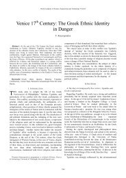
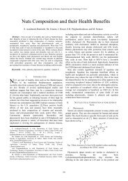
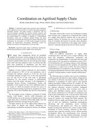
These processes are those liquid-gas heat exchangers are<br />
applied to between <str<strong>on</strong>g>of</str<strong>on</strong>g> two cycles. One <str<strong>on</strong>g>of</str<strong>on</strong>g> these processes is that<br />
sub-cooled liquid refrigerant which is bypassed from<br />
inter-cooler in the ethylene cycle <str<strong>on</strong>g>and</str<strong>on</strong>g> hot gaseous refrigerant<br />
from outlet <str<strong>on</strong>g>of</str<strong>on</strong>g> high pressure compressor in the methane cycle<br />
are exchanged the heat in the liquid-gas heat exchanger to<br />
liquefy the hot gaseous methane (process2). The other process is<br />
that <strong>on</strong>e more liquid-gas heat exchanger is applied to between <str<strong>on</strong>g>of</str<strong>on</strong>g><br />
propane <str<strong>on</strong>g>and</str<strong>on</strong>g> ethylene cycle (process3) <strong>on</strong> the process2. Fig. 1<br />
shows about process 2.<br />
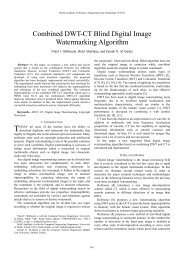
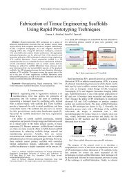
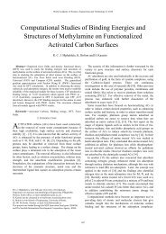
D. <str<strong>on</strong>g>C3MR</str<strong>on</strong>g>(Propane Mixed Refrigerant) Process<br />
This process are formed two cycles such as MR (Mixed<br />
Refrigerant) cycle <str<strong>on</strong>g>and</str<strong>on</strong>g> C3 (Propane) cycle. <strong>Natural</strong> gas is<br />
pre-cooled to about -35 o C through C3 cooler, than liquefied at<br />
-160 o C in the MR heat exchanger. This process is shown in the<br />
Fig.2
III. SIMULATION CONDITION<br />
A. C<strong>on</strong>diti<strong>on</strong> <str<strong>on</strong>g>of</str<strong>on</strong>g> simulati<strong>on</strong><br />
In this simulati<strong>on</strong>, a feed gas compositi<strong>on</strong> is assumed with<br />
treated natural gas which is removed acid gas, water, mercury<br />
<str<strong>on</strong>g>and</str<strong>on</strong>g> heavy hydrocarb<strong>on</strong>s from Nigeria LNG plant. Table 1<br />
shows feed gas <str<strong>on</strong>g>and</str<strong>on</strong>g> MR compositi<strong>on</strong>. Assumed c<strong>on</strong>diti<strong>on</strong>s <str<strong>on</strong>g>of</str<strong>on</strong>g><br />
simulati<strong>on</strong> <str<strong>on</strong>g>of</str<strong>on</strong>g> are shown in Table 2. Feed gas mass flow is set<br />
based <strong>on</strong> trane capacity 5MTPA (Milli<strong>on</strong> T<strong>on</strong> Per Annum, a<br />
bypass flow rate <str<strong>on</strong>g>of</str<strong>on</strong>g> cascade process is set 15% <str<strong>on</strong>g>of</str<strong>on</strong>g> mass flow <str<strong>on</strong>g>of</str<strong>on</strong>g><br />
each cycle, a middle pressure is set 50% <str<strong>on</strong>g>of</str<strong>on</strong>g> high pressure <str<strong>on</strong>g>and</str<strong>on</strong>g><br />
outlet pressure <str<strong>on</strong>g>of</str<strong>on</strong>g> expansi<strong>on</strong> valve <str<strong>on</strong>g>of</str<strong>on</strong>g> the intercooler inlet side is<br />
assumed same as middle pressure.<br />
Comp<strong>on</strong>ent<br />
TABLE I<br />
COMPOSITION OF NATURAL GAS & MR<br />
Mole fracti<strong>on</strong> <str<strong>on</strong>g>of</str<strong>on</strong>g><br />
<str<strong>on</strong>g>Cascade</str<strong>on</strong>g>[%]<br />
Mole fracti<strong>on</strong> <str<strong>on</strong>g>of</str<strong>on</strong>g><br />
MR[%]<br />
Nitrogen 0.007 0.02<br />
Methane 0.82 0.44<br />
Ethane 0.112 0.39<br />
Propane 0.04 0.15<br />
iso-Butane 0.012 -<br />
n-Butane 0.009 -<br />
Total 1 1<br />
B. Equati<strong>on</strong>s<br />
World Academy <str<strong>on</strong>g>of</str<strong>on</strong>g> Science, Engineering <str<strong>on</strong>g>and</str<strong>on</strong>g> Technology 35 2009<br />
TABLE II<br />
ASSUMED CONDITIONS<br />
Parameter <str<strong>on</strong>g>Cascade</str<strong>on</strong>g> <str<strong>on</strong>g>C3MR</str<strong>on</strong>g><br />
Refrigerant [-]<br />
Methane,<br />
Ethylene, Propane<br />
MR<br />
Bypass flow rate [%] 50 -<br />
Middle pressure [%] 50 -<br />
Feed gas mass flow rate [kg/s] 158.5<br />
Feed gas temperature [ ] 32<br />
Feed gas pressure [kPa] 5000<br />
2 nd fluid temperature [ ] 40<br />
Two kinds <str<strong>on</strong>g>of</str<strong>on</strong>g> main equati<strong>on</strong>s are used for the liquefacti<strong>on</strong><br />
simulati<strong>on</strong>.[13] The Peng- Robins<strong>on</strong> equati<strong>on</strong> <str<strong>on</strong>g>of</str<strong>on</strong>g> state applies<br />
functi<strong>on</strong>ality to some specific comp<strong>on</strong>ent-comp<strong>on</strong>ent<br />
interacti<strong>on</strong> parameters, which can be used in the calculati<strong>on</strong> <str<strong>on</strong>g>of</str<strong>on</strong>g><br />
phase equilibrium.<br />
It is written by<br />
RT<br />
P <br />
V b V<br />
a <br />
b <br />
N<br />
<br />
i 1 j 1<br />
N<br />
<br />
i 1<br />
N<br />
a b<br />
i<br />
a a<br />
i<br />
i<br />
V b<br />
bV<br />
b<br />
j<br />
ab<br />
a a 1 k <br />
i<br />
j<br />
a<br />
Where P [Pa] is a pressure, R [N·m/kg·K] is a gas c<strong>on</strong>stant, T<br />
[K] is a temperature, V [m3/kg] is a specific volume, a <str<strong>on</strong>g>and</str<strong>on</strong>g> b are<br />
the c<strong>on</strong>stants relating to the gas species, x is mole fracti<strong>on</strong> <str<strong>on</strong>g>of</str<strong>on</strong>g> a<br />
certain comp<strong>on</strong>ent, k is binary interacti<strong>on</strong> coefficient.<br />
It is rewritten as<br />
3<br />
P Z <br />
aP<br />
A <br />
2<br />
2<br />
2 3<br />
1 BZ<br />
A 2B<br />
3B<br />
Z AB<br />
B B <br />
bP<br />
B <br />
2 RT RT<br />
Fig.1 Schematic diagram <str<strong>on</strong>g>of</str<strong>on</strong>g> cascade process using liquid-gas heat exchanger<br />
186<br />
ij<br />
.<br />
0<br />
(1)<br />
(2)
Where Z is a c<strong>on</strong>stringent factor, A <str<strong>on</strong>g>and</str<strong>on</strong>g> B are the coefficients<br />
relating to the gas state parameters.<br />
The Lee-Kesler-Plocker equati<strong>on</strong> is an accurate general<br />
method for n<strong>on</strong>-polar substances <str<strong>on</strong>g>and</str<strong>on</strong>g> mixtures, which can be<br />
used in the calculati<strong>on</strong> <str<strong>on</strong>g>of</str<strong>on</strong>g> enthalpy <str<strong>on</strong>g>and</str<strong>on</strong>g> entropy <str<strong>on</strong>g>of</str<strong>on</strong>g> mixed<br />
comp<strong>on</strong>ents.<br />
It is given by<br />
<br />
<br />
P Z<br />
<br />
<br />
0 <br />
r o r Z Z<br />
(3)<br />
where w is an acentric factor, o <str<strong>on</strong>g>and</str<strong>on</strong>g> r denote the relevant<br />
parameters <str<strong>on</strong>g>of</str<strong>on</strong>g> simple <str<strong>on</strong>g>and</str<strong>on</strong>g> reference liquids.<br />
A. <str<strong>on</strong>g>Cascade</str<strong>on</strong>g> process<br />
IV. RESULTS AND CONSIDERATIONS<br />
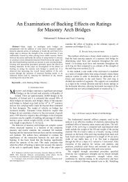
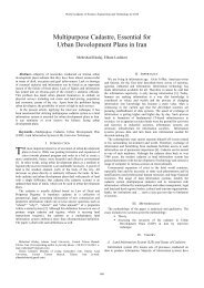
Fig. 4 shows comparis<strong>on</strong> <str<strong>on</strong>g>of</str<strong>on</strong>g> variati<strong>on</strong> <str<strong>on</strong>g>of</str<strong>on</strong>g> each refrigerant mass<br />
flow rate. Only mass flow rate <str<strong>on</strong>g>of</str<strong>on</strong>g> propane <str<strong>on</strong>g>of</str<strong>on</strong>g> Process 2<br />
decreased about 2.4%, but that <str<strong>on</strong>g>of</str<strong>on</strong>g> ethylene <str<strong>on</strong>g>and</str<strong>on</strong>g> methane<br />
increased about 8.2% <str<strong>on</strong>g>and</str<strong>on</strong>g> 4.4% than those <str<strong>on</strong>g>of</str<strong>on</strong>g> process1. Mass<br />
flow rate <str<strong>on</strong>g>of</str<strong>on</strong>g> all refrigerants <str<strong>on</strong>g>of</str<strong>on</strong>g> Process 3 are increased about 2.3<br />
~ 9.4%. According to supplement <str<strong>on</strong>g>of</str<strong>on</strong>g> liquid-gas heat exchanger,<br />
bypass mass flow rate increased <str<strong>on</strong>g>and</str<strong>on</strong>g> mass flow rate <str<strong>on</strong>g>of</str<strong>on</strong>g><br />
refrigerant to each cycle’s evaporator also decreased then that <str<strong>on</strong>g>of</str<strong>on</strong>g><br />
whole cycles increased. The other h<str<strong>on</strong>g>and</str<strong>on</strong>g>, temperature <str<strong>on</strong>g>of</str<strong>on</strong>g> inlet <str<strong>on</strong>g>of</str<strong>on</strong>g><br />
compressor is drop owing to increment <str<strong>on</strong>g>of</str<strong>on</strong>g> sub-cooling <str<strong>on</strong>g>and</str<strong>on</strong>g> then<br />
the compressi<strong>on</strong> work is decreased. Therefore, we can c<strong>on</strong>clude<br />
that COP is improved.<br />
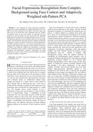
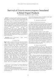
Performances <str<strong>on</strong>g>of</str<strong>on</strong>g> each process in a same c<strong>on</strong>diti<strong>on</strong>s such as<br />
liquefacti<strong>on</strong> rate <str<strong>on</strong>g>and</str<strong>on</strong>g> temperature are shown in Fig. 5.<br />
Refrigerati<strong>on</strong> capacity <str<strong>on</strong>g>of</str<strong>on</strong>g> process 2 is 0.9% higher <str<strong>on</strong>g>and</str<strong>on</strong>g> that <str<strong>on</strong>g>of</str<strong>on</strong>g><br />
process 3 is lower than that <str<strong>on</strong>g>of</str<strong>on</strong>g> process 1. Since a state <str<strong>on</strong>g>of</str<strong>on</strong>g> high<br />
temperature <str<strong>on</strong>g>of</str<strong>on</strong>g> methane is cooled with bypassed ethylene<br />
World Academy <str<strong>on</strong>g>of</str<strong>on</strong>g> Science, Engineering <str<strong>on</strong>g>and</str<strong>on</strong>g> Technology 35 2009<br />
Mass flow rate [kg/s]<br />
Capacity [MW]<br />
1400<br />
1200<br />
1000<br />
800<br />
600<br />
400<br />
200<br />
500<br />
400<br />
300<br />
200<br />
100<br />
Fig.2 Schematic diagram <str<strong>on</strong>g>of</str<strong>on</strong>g> <str<strong>on</strong>g>C3MR</str<strong>on</strong>g><br />
187<br />
0<br />
0<br />
C3 C2<br />
Refrigerants [ - ]<br />
C1<br />
Fig. 4 Comparis<strong>on</strong> <str<strong>on</strong>g>of</str<strong>on</strong>g> refrigerant mass flow rate<br />
R W COP<br />
Performance [ - ]<br />
Fig. 5 Comparis<strong>on</strong> <str<strong>on</strong>g>of</str<strong>on</strong>g> performance<br />
Process1<br />
Process2<br />
Process3<br />
Process1<br />
Process2<br />
Process3<br />
1.6<br />
1.4<br />
1.2<br />
1.0<br />
0.8<br />
0.6<br />
0.4<br />
0.2<br />
0.0<br />
COP [ - ]
Specific power [kJ/kg]<br />
2500<br />
2000<br />
1500<br />
1000<br />
500<br />
0<br />
Process1 Process2 Process3<br />
Type [ - ]<br />
Fig. 6 Comparis<strong>on</strong> <str<strong>on</strong>g>of</str<strong>on</strong>g> specific power<br />
c<strong>on</strong>densing temperature is decreased as a result, refrigerati<strong>on</strong><br />
capacity <str<strong>on</strong>g>of</str<strong>on</strong>g> process 2 increased. Refrigerati<strong>on</strong> capacity <str<strong>on</strong>g>of</str<strong>on</strong>g><br />
Process 3 decreased, even though c<strong>on</strong>densing temperature is<br />
lower. This is because, mass flow rate <str<strong>on</strong>g>of</str<strong>on</strong>g> propane to inlet <str<strong>on</strong>g>of</str<strong>on</strong>g><br />
propane evaporator which has dominant influence <strong>on</strong> refrigerant<br />
capacity is decreased as bypassed.<br />
Compressor work <str<strong>on</strong>g>of</str<strong>on</strong>g> process 2 <str<strong>on</strong>g>and</str<strong>on</strong>g> that <str<strong>on</strong>g>of</str<strong>on</strong>g> process 3 are<br />
11.44% <str<strong>on</strong>g>and</str<strong>on</strong>g> 8.26% lower than that <str<strong>on</strong>g>of</str<strong>on</strong>g> process 1. In this figure,<br />
process 3 shows higher compressor work than that <str<strong>on</strong>g>of</str<strong>on</strong>g> Process 2.<br />
This is because, requirement <str<strong>on</strong>g>of</str<strong>on</strong>g> refrigerant is increased with<br />
decrement <str<strong>on</strong>g>of</str<strong>on</strong>g> mass flow rate <str<strong>on</strong>g>of</str<strong>on</strong>g> propane to inlet <str<strong>on</strong>g>of</str<strong>on</strong>g> propane<br />
evaporator as liquid-gas heat exchanger is added. COP means<br />
efficiency <str<strong>on</strong>g>of</str<strong>on</strong>g> system <str<strong>on</strong>g>and</str<strong>on</strong>g> that is calculated by refrigerati<strong>on</strong><br />
capacity per compressor work. COP <str<strong>on</strong>g>of</str<strong>on</strong>g> process 2 shows the<br />
highest increment ratio about 13.9%.<br />
Fig. 6 <str<strong>on</strong>g>and</str<strong>on</strong>g> Fig. 7 show power c<strong>on</strong>sumpti<strong>on</strong> per productivity <str<strong>on</strong>g>of</str<strong>on</strong>g><br />
LNG <str<strong>on</strong>g>and</str<strong>on</strong>g> productivity <str<strong>on</strong>g>of</str<strong>on</strong>g> LNG per power requirement. Power<br />
c<strong>on</strong>sumpti<strong>on</strong> per productivity <str<strong>on</strong>g>of</str<strong>on</strong>g> LNG <str<strong>on</strong>g>of</str<strong>on</strong>g> Process 2 is the largest<br />
decrement ratio about 11.44% <str<strong>on</strong>g>and</str<strong>on</strong>g> productivity <str<strong>on</strong>g>of</str<strong>on</strong>g> LNG per<br />
power requirement <str<strong>on</strong>g>of</str<strong>on</strong>g> Process 2 is the highest increment ratio<br />
about 1.68%. As a result, performance <str<strong>on</strong>g>and</str<strong>on</strong>g> efficiency <str<strong>on</strong>g>of</str<strong>on</strong>g> process<br />
2 is expected that is the best in these processes.<br />
Productivity [kg/h/kW]<br />
1.8<br />
1.6<br />
1.4<br />
1.2<br />
1.0<br />
0.8<br />
0.6<br />
0.4<br />
0.2<br />
0.0<br />
Process1 Process2<br />
Type [ - ]<br />
Process3<br />
Fig. 7 Comparis<strong>on</strong> <str<strong>on</strong>g>of</str<strong>on</strong>g> productivity<br />
World Academy <str<strong>on</strong>g>of</str<strong>on</strong>g> Science, Engineering <str<strong>on</strong>g>and</str<strong>on</strong>g> Technology 35 2009<br />
188<br />
B. <str<strong>on</strong>g>C3MR</str<strong>on</strong>g> process<br />
This process has the highest performance <str<strong>on</strong>g>and</str<strong>on</strong>g> efficiencyt in<br />
existing liquefacti<strong>on</strong> plants <str<strong>on</strong>g>and</str<strong>on</strong>g> it has a positi<strong>on</strong> up to 70% in<br />
liquefacti<strong>on</strong> plant market in the world. For these reas<strong>on</strong>s, it is<br />
simulated <str<strong>on</strong>g>and</str<strong>on</strong>g> analyzed. Performances <str<strong>on</strong>g>of</str<strong>on</strong>g> <str<strong>on</strong>g>C3MR</str<strong>on</strong>g> is shown in<br />
Table 3.<br />
TABLE III<br />
PERFORMANCES OF <str<strong>on</strong>g>C3MR</str<strong>on</strong>g><br />
Process<br />
Compressor<br />
Work<br />
[MW]<br />
Refrigerant<br />
Capacity<br />
[MW]<br />
COP<br />
[-]<br />
Specific<br />
Power<br />
[kJ/kg]<br />
<str<strong>on</strong>g>C3MR</str<strong>on</strong>g> 171.9 366.1 2.13 934.6<br />
<str<strong>on</strong>g>Cascade</str<strong>on</strong>g> 312.1 394.5 1.26 1,968.5<br />
Its performances show differece cuased by c<strong>on</strong>taing heat<br />
exhcang line such as recovery <str<strong>on</strong>g>of</str<strong>on</strong>g> waste heat from cascade in<br />
principal prameter. Later <strong>on</strong>, research <strong>on</strong> <str<strong>on</strong>g>C3MR</str<strong>on</strong>g> process will be<br />
proceeded <str<strong>on</strong>g>and</str<strong>on</strong>g> we will develop more efficient <str<strong>on</strong>g>C3MR</str<strong>on</strong>g> process.<br />
V. CONCLUSIONS<br />
In this study, liquefacti<strong>on</strong> processes are simulated <str<strong>on</strong>g>and</str<strong>on</strong>g><br />
analyzed focused <strong>on</strong> decrement <str<strong>on</strong>g>of</str<strong>on</strong>g> power c<strong>on</strong>sumpti<strong>on</strong> per<br />
productivity <str<strong>on</strong>g>of</str<strong>on</strong>g> LNG <str<strong>on</strong>g>and</str<strong>on</strong>g> increment <str<strong>on</strong>g>of</str<strong>on</strong>g> productivity <str<strong>on</strong>g>of</str<strong>on</strong>g> LNG per<br />
power requirement by redusing compressor work which has a<br />
great influence <strong>on</strong> efficiency <str<strong>on</strong>g>of</str<strong>on</strong>g> liquefacti<strong>on</strong> process. Results are<br />
showed as follows.<br />
1. Mass flow rate <str<strong>on</strong>g>of</str<strong>on</strong>g> <strong>on</strong>ly propane <str<strong>on</strong>g>of</str<strong>on</strong>g> process 2 decreased<br />
about 2.4%, but that <str<strong>on</strong>g>of</str<strong>on</strong>g> the others increased about 2.3 ~ 9.4%.<br />
2. Refrigerati<strong>on</strong> capacity <str<strong>on</strong>g>of</str<strong>on</strong>g> Process 2 increasd, but that <str<strong>on</strong>g>of</str<strong>on</strong>g><br />
process 2 decreased compared with process 1. Compressor<br />
works <str<strong>on</strong>g>of</str<strong>on</strong>g> Process 2 <str<strong>on</strong>g>and</str<strong>on</strong>g> process 3 decreased <str<strong>on</strong>g>and</str<strong>on</strong>g> COP <str<strong>on</strong>g>of</str<strong>on</strong>g> process<br />
2 shows the highest increment ratio about 13.9%.<br />
3. Power c<strong>on</strong>sumpti<strong>on</strong> per productivity <str<strong>on</strong>g>of</str<strong>on</strong>g> LNG <str<strong>on</strong>g>of</str<strong>on</strong>g> Process 2<br />
is the largest decrement ratio about 11.44% <str<strong>on</strong>g>and</str<strong>on</strong>g> productivity <str<strong>on</strong>g>of</str<strong>on</strong>g><br />
LNG per power requirement <str<strong>on</strong>g>of</str<strong>on</strong>g> Process 2 is the highest<br />
increment ratio about 1.68%.<br />
In this research, process 2 is the top ranked with high<br />
Efficiency in cascade processes <str<strong>on</strong>g>and</str<strong>on</strong>g> we will use <str<strong>on</strong>g>of</str<strong>on</strong>g> these result<br />
to research <strong>on</strong> improvement <str<strong>on</strong>g>of</str<strong>on</strong>g> performance <str<strong>on</strong>g>and</str<strong>on</strong>g> efficiency in<br />
liquefacti<strong>on</strong> process.<br />
ACKNOWLEDGMENT<br />
This research was supported by a grant from the <strong>Gas</strong> Plant<br />
R&D Center funded by the Ministry <str<strong>on</strong>g>of</str<strong>on</strong>g> L<str<strong>on</strong>g>and</str<strong>on</strong>g>, Transportati<strong>on</strong><br />
<str<strong>on</strong>g>and</str<strong>on</strong>g> Maritime Affairs (MLTM) <str<strong>on</strong>g>of</str<strong>on</strong>g> the Korean government.<br />
REFERENCES<br />
[1] Sang gyu Lee, Kun hyung Choe, Young myung Yang, The state <str<strong>on</strong>g>of</str<strong>on</strong>g> art <str<strong>on</strong>g>of</str<strong>on</strong>g><br />
LNG Liquefacti<strong>on</strong> Plant Technologies, The 3rd Korean C<strong>on</strong>gress <str<strong>on</strong>g>of</str<strong>on</strong>g><br />
Refrigerati<strong>on</strong>, vol. 3, pp. 65-68. 2009<br />
[2] H. S. Chang,, B. N. Lee, B. S. Gu, A Raise Plan <str<strong>on</strong>g>of</str<strong>on</strong>g> competitiveness<br />
<str<strong>on</strong>g>of</str<strong>on</strong>g> Internal Company in the overseas Plant market,<br />
C<strong>on</strong>structi<strong>on</strong> & Ec<strong>on</strong>omy Research Institute <str<strong>on</strong>g>of</str<strong>on</strong>g> Korea, Vol. 19, pp. 2-30,<br />
2007<br />
[3] Seung Taek Oh, Ho Saeng Lee, Jung In Yo<strong>on</strong>, Sang Gyu Lee,<br />
Development <str<strong>on</strong>g>of</str<strong>on</strong>g> LNG Liquefacti<strong>on</strong> Process, Journal <str<strong>on</strong>g>of</str<strong>on</strong>g> the SAREK, Vol.<br />
38, No. 3, pp. 13-17, 2009
[4] D. L. Andress, “The Phillips Optimized <str<strong>on</strong>g>Cascade</str<strong>on</strong>g> LNG Process a Quarter<br />
Century <str<strong>on</strong>g>of</str<strong>on</strong>g> Improvement”, The Permissi<strong>on</strong> <str<strong>on</strong>g>of</str<strong>on</strong>g> the Institute <str<strong>on</strong>g>of</str<strong>on</strong>g> <strong>Gas</strong><br />
Technology, 1996<br />
[5] Yoshitugi Kikkawa et. al, “Development <str<strong>on</strong>g>of</str<strong>on</strong>g> Liquefacti<strong>on</strong> Process for<br />
<strong>Natural</strong> <strong>Gas</strong>”, Journal <str<strong>on</strong>g>of</str<strong>on</strong>g> Chemical Engineering <str<strong>on</strong>g>of</str<strong>on</strong>g> Japan, Vol. 30, No. 4,<br />
pp. 625-630, 1997<br />
[6] L. Terry, “Comparis<strong>on</strong> <str<strong>on</strong>g>of</str<strong>on</strong>g> Liquefacti<strong>on</strong> Process”, LNG Journal 21, No. 3,<br />
pp. 28-33, 1998<br />
[7] Wen-sheng Cao et. al, “Parameter Comparis<strong>on</strong> <str<strong>on</strong>g>of</str<strong>on</strong>g> Two Small-scale<br />
<strong>Natural</strong> <strong>Gas</strong> Liquefacti<strong>on</strong> Process in Skid-mounted Packages”, Applies<br />
Thermal Engineering, No. 26, pp. 898-904, 2006<br />
[8] Seung Taek Oh, Hyun Woo Kim, Ho Saeng Lee, Gye<strong>on</strong>g Beom Yi, Jung<br />
In Yo<strong>on</strong>, Sang Gyu Lee, Simulati<strong>on</strong> <str<strong>on</strong>g>of</str<strong>on</strong>g> LNG liquefacti<strong>on</strong> cycle using<br />
[9] two stage intercooler, Proceedings <str<strong>on</strong>g>of</str<strong>on</strong>g> KIGAS Spring c<strong>on</strong>ference, pp.<br />
225-228, 2009<br />
[10] H. S. Lee, S. T. Oh, H. W. Kim, J. I. Yo<strong>on</strong>, G. B. Yi, S. G. Lee, “Analysis<br />
<str<strong>on</strong>g>of</str<strong>on</strong>g> Cryogenic Refrigerati<strong>on</strong> <str<strong>on</strong>g>Cycle</str<strong>on</strong>g> using Two Stage Intercooler”, 5th<br />
Internati<strong>on</strong>al C<strong>on</strong>ference <strong>on</strong> Diffusi<strong>on</strong> in Solids <str<strong>on</strong>g>and</str<strong>on</strong>g> Liquids, pp. 40-41,<br />
2009<br />
[11] H. S. Lee, S. T. Oh, H. W. Kim, W. J. Choi, J. I. Yo<strong>on</strong> <str<strong>on</strong>g>and</str<strong>on</strong>g> S. G. Lee,<br />
Comparis<strong>on</strong> <str<strong>on</strong>g>of</str<strong>on</strong>g> Performance <str<strong>on</strong>g>of</str<strong>on</strong>g> Cryogenic Liquefacti<strong>on</strong> Process with<br />
Exp<str<strong>on</strong>g>and</str<strong>on</strong>g>er, Proceedings <str<strong>on</strong>g>of</str<strong>on</strong>g> the KSPSE Spring C<strong>on</strong>ference, pp. 250-254,<br />
2009<br />
[12] Seung-taek Oh, Ho-saeng Lee, Gye<strong>on</strong>g-Beom Yi, Jung-in Yo<strong>on</strong>,<br />
Sang-gyu Lee, <str<strong>on</strong>g>Characteristics</str<strong>on</strong>g> <str<strong>on</strong>g>of</str<strong>on</strong>g> cryogenic liquefacti<strong>on</strong> cycle using two<br />
stage compressi<strong>on</strong> type, Proceedings <str<strong>on</strong>g>of</str<strong>on</strong>g> the SAREK Summer Annual<br />
C<strong>on</strong>ference, pp. 109, 2009<br />
[13] C. R. Robert, “The Properties <str<strong>on</strong>g>of</str<strong>on</strong>g> <strong>Gas</strong>es a Liquid, 4 th Editi<strong>on</strong>,<br />
McGraw-Hill Book Company, 1987<br />
World Academy <str<strong>on</strong>g>of</str<strong>on</strong>g> Science, Engineering <str<strong>on</strong>g>and</str<strong>on</strong>g> Technology 35 2009<br />
189