The Castrip® Process for the Twin-Roll Casting
The Castrip® Process for the Twin-Roll Casting
The Castrip® Process for the Twin-Roll Casting

You also want an ePaper? Increase the reach of your titles
YUMPU automatically turns print PDFs into web optimized ePapers that Google loves.
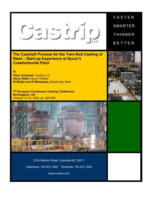
<strong>The</strong> <strong>Castrip®</strong> <strong>Process</strong> <strong>for</strong> <strong>the</strong> <strong>Twin</strong>-<strong>Roll</strong> <strong>Casting</strong> of<br />
Steel – Start-up Experience at Nucor’s<br />
Craw<strong>for</strong>dsville Plant<br />
By<br />
Peter Campbell, Castrip LLC<br />
Gerry Gillen, Nucor Indiana<br />
W Blejde and R Mahapatra, BlueScope Steel<br />
4 th European Continuous <strong>Casting</strong> Conference<br />
Birmingham, UK<br />
October 14-16, 2002; pp. 882-890<br />
2100 Rex<strong>for</strong>d Road, Charlotte NC 28211<br />
Telephone: 704.972.1820 Facsimile: 704.972.1829<br />
www.castrip.com<br />
FASTER<br />
SMARTER<br />
THINNER<br />
BETTER
THE CASTRIP ® PROCESS FOR TWIN-ROLL CASTING OF STEEL –<br />
START-UP EXPERIENCE AT NUCOR’S CRAWFORDSVILLE PLANT<br />
Peter Campbell * , Gerry Gillen + , Wal Blejde # and Rama Mahapatra #<br />
With hot commissioning started in early May 2002, Nucor Craw<strong>for</strong>dsville has become <strong>the</strong><br />
first fully commercial strip casting facility in <strong>the</strong> world. Employing <strong>the</strong> CASTRIP ® twin-roll<br />
casting technology, Nucor aims to cast steel strip at 1.0 to 2.0 mm in thickness with a width<br />
of between 1000 and 2000 mm. At casting speeds approaching 100 m/min, <strong>the</strong> Nucor caster<br />
is capable of producing 500,000 tons per year. Over <strong>the</strong> past decade, BHP Steel and IHI have<br />
developed <strong>the</strong> CASTRIP process through pilot plant and full-scale development facilities in<br />
Australia; Nucor joined <strong>the</strong> ef<strong>for</strong>t in 2000. <strong>The</strong> following paper includes a discussion of <strong>the</strong><br />
key process metallurgy breakthrough areas associated with <strong>the</strong> technology and a brief<br />
background on its development. A description of <strong>the</strong> Craw<strong>for</strong>dsville CASTRIP facility is also<br />
provided.<br />
INTRODUCTION<br />
Near-net-shape casting of metal products has long been of interest to metallurgists and <strong>the</strong><br />
metals industry. Obvious savings in equipment plus efficiencies related to hot and cold<br />
working as well as reheating have been <strong>the</strong> main driving <strong>for</strong>ce. For more than a decade, BHP<br />
Steel and IHI (Ishikawajima-Harima Heavy Industries) collaborated on twin-roll casting<br />
design at development facilities in Wollongong, Australia. <strong>The</strong> codename <strong>for</strong> this venture<br />
was Project ‘M’ and <strong>the</strong> project covered laboratory, pilot plant and full-scale development<br />
facilities. In 2000, Nucor Corporation joined <strong>for</strong>ces with <strong>the</strong> team, <strong>for</strong>ming Castrip LLC, a<br />
joint venture company aimed at commercializing <strong>the</strong> new technology. Construction is now<br />
complete at Craw<strong>for</strong>dsville, Indiana, also home to <strong>the</strong> world’s first thin slab caster. Hot<br />
commissioning and casting trials began in early May and <strong>the</strong> Nucor plant is expected to ramp<br />
up commercial production over <strong>the</strong> next 6 to 12 months.<br />
For <strong>the</strong> past decade or so, strip casting of steels has been an interesting technical curiosity <strong>for</strong><br />
<strong>the</strong> steelmaking community. Many projects and collaborative ef<strong>for</strong>ts have been initiated,<br />
practically worldwide; however none has been run at a full commercial level <strong>for</strong> extended<br />
periods. With <strong>the</strong> construction of <strong>the</strong> Nucor CASTRIP ® facility at Craw<strong>for</strong>dsville, <strong>the</strong> direct<br />
casting of sheet products will become a commercial reality. <strong>The</strong> following paper describes<br />
some of <strong>the</strong> key process fundamentals of CASTRIP technology and provides details on <strong>the</strong><br />
first installation at Craw<strong>for</strong>dsville. Physical properties <strong>for</strong> typical CASTRIP products are also<br />
included.<br />
* Castrip LLC, Charlotte NC USA<br />
+ Nucor Steel Indiana, Craw<strong>for</strong>dsville IN USA<br />
# BHP Steel, Craw<strong>for</strong>dsville IN USA<br />
CASTRIP ® is a registered trademark of Castrip LLC
PROCESS OVERVIEW<br />
<strong>The</strong> CASTRIP process is based upon <strong>the</strong> same concepts that Henry Bessemer patented in <strong>the</strong><br />
mid-19 th century. Figure 1 shows a simple schematic of <strong>the</strong> basics of <strong>the</strong> process – two<br />
counter-rotating rolls that provide a surface or mold against which molten steel solidifies. As<br />
<strong>the</strong> figure indicates, <strong>the</strong> steel begins to solidify against <strong>the</strong> rolls just below <strong>the</strong> meniscus and<br />
shell growth continues as <strong>the</strong>y move as it moves downwards through <strong>the</strong> melt pool. At <strong>the</strong><br />
roll nip or pinch-point, <strong>the</strong> two shells are essentially fused toge<strong>the</strong>r <strong>for</strong>ming a continuous<br />
strip, which <strong>the</strong>n exits <strong>the</strong> caster in a downward direction.<br />
Counter-rotating <strong>Roll</strong>s<br />
Liquid Metal<br />
Solid Strip<br />
Fig. 1 – Simple schematic of twin-roll strip casting process.<br />
Although <strong>the</strong> concept is extremely simple, its application at a commercially viable production<br />
level has proven to be extremely difficult. Several technical advancements have occurred in<br />
recent years that have made twin roll casting possible at a commercial level. <strong>The</strong>se include:<br />
High speed computing and process control<br />
Advanced ceramics and materials (including copper alloys)<br />
Sensing technology<br />
Ma<strong>the</strong>matical modeling of physical phenomena<br />
In addition to <strong>the</strong>se advancements, <strong>the</strong> Project ‘M’ team had to significantly increase <strong>the</strong><br />
body of knowledge related to several key areas of process metallurgy directly connected to<br />
<strong>the</strong> twin-roll process. Previous papers have discussed <strong>the</strong> development of <strong>the</strong> CASTRIP<br />
process (1-4); <strong>the</strong>se advancements or breakthroughs are what sets CASTRIP technology apart<br />
from o<strong>the</strong>r twin roll processes and can be divided into 5 key areas:<br />
1. Metal delivery<br />
2. Early solidification<br />
3. Edge containment<br />
4. <strong>Roll</strong> distortion<br />
5. Refractories
Metal delivery - Metal delivery to <strong>the</strong> melt pool is critical <strong>for</strong> a number of reasons. Unlike<br />
conventional casting, <strong>the</strong> melt pool is very small in <strong>the</strong> CASTRIP process. This is particularly<br />
so due to <strong>the</strong> 500-mm diameter casting rolls, which are significantly smaller than rolls<br />
utilized in o<strong>the</strong>r twin roll casting projects (5). As a result, <strong>the</strong> ratio of mass flow rate into <strong>the</strong><br />
pool divided by <strong>the</strong> pool volume is nearly an order of magnitude higher in <strong>the</strong> CASTRIP<br />
process compared to slab casting. Thus, <strong>the</strong> metal delivery nozzle or core nozzle utilized in<br />
<strong>the</strong> CASTRIP process is completely different than that used <strong>for</strong> conventional casting, with<br />
major emphasis on reducing <strong>the</strong> turbulence in <strong>the</strong> steel as it enters <strong>the</strong> melt pool plus <strong>the</strong>and<br />
<strong>the</strong> need <strong>for</strong> effective distribution of metal along <strong>the</strong> roll length. A fur<strong>the</strong>r requirement of <strong>the</strong><br />
metal delivery system is to provide metal to <strong>the</strong> meniscus in a stable and repeatable manner.<br />
Any disturbance at <strong>the</strong> meniscus invariably manifests itself as a strip defect; thus <strong>the</strong> process<br />
must be stable and in control at all times to ensure excellent surface quality.<br />
Meniscus<br />
<strong>Casting</strong> <strong>Roll</strong><br />
Nozzle<br />
Melt<br />
(a) (b)<br />
Mould<br />
Slag Rim<br />
Flux<br />
Meniscus<br />
SEN<br />
Fig. 2 – Comparison of <strong>the</strong> meniscus region in (a) <strong>the</strong> CASTRIP process and (b) conventional<br />
slab casting.<br />
Early solidification - Most of <strong>the</strong> ef<strong>for</strong>t related to <strong>the</strong> understanding of solidification in steels<br />
has been confined to continuous casting over <strong>the</strong> past 20 years. <strong>The</strong>re are some major<br />
differences between CASTRIP technology and slab casting that have significant effects on<br />
<strong>the</strong> <strong>for</strong>mation and growth of <strong>the</strong> shell. Figure 2 shows a close-up of <strong>the</strong> meniscus area in both<br />
processes. Among <strong>the</strong> main differences between <strong>the</strong> two processes are, that <strong>the</strong> CASTRIP<br />
technology does not use any type of mold powder or lubrication and that <strong>the</strong> mold (roll) and<br />
steel shell remain in direct contactmaintain <strong>the</strong> same velocity, i.e. no mold oscillation. As a<br />
resultBecause <strong>the</strong>re is no mold powder, <strong>the</strong>re is significantly better contact between <strong>the</strong> roll<br />
surface and solidifying shell, starting at <strong>the</strong> meniscus and extending down to exit at <strong>the</strong> roll<br />
nip. Significant work has been done in trying to understand <strong>the</strong> mechanisms <strong>for</strong> shell
<strong>for</strong>mation and growth as well as heat transfer between <strong>the</strong> steel and roll surface. This work<br />
has been described previously by Mukunthan et al. (1) and it is critical that <strong>the</strong> variables<br />
affecting <strong>the</strong> early solidification of <strong>the</strong> shell and its subsequent growth be understood <strong>for</strong> <strong>the</strong><br />
production of quality strip. Recently, independent research work at Carnegie Mellon<br />
University has provided fur<strong>the</strong>r detail related to interfacial phenomena and <strong>the</strong> solidification<br />
of carbon steels during strip casting (6).<br />
One of <strong>the</strong> many problems that can arise from poor control of solidification and uneven shell<br />
growth is depicted in Figure 3. As indicated in <strong>the</strong> X-ray map taken of a strip with poor<br />
solidification control (Figure 3 (a)), <strong>the</strong> <strong>for</strong>mation of porosity is a result. This is because <strong>the</strong><br />
uneven solidification of <strong>the</strong> shell creates an uneven solidification front, which can trap liquid<br />
steel below <strong>the</strong> roll nip. Bringing nucleation and early solidification under control results in a<br />
smooth solidification front, <strong>the</strong>reby preventing porosity (Figure 3 (b)).<br />
(a) (b)<br />
Fig. 3 – X-ray maps indicating <strong>the</strong> level of porosity in <strong>the</strong> solidified steel strip, (a) early casts<br />
showing porosity and (b) later casts with no porosity.<br />
Edge containment – Although most of <strong>the</strong> surface area of <strong>the</strong> solidifying strip is confined to<br />
contact against <strong>the</strong> face of <strong>the</strong> rolls, <strong>the</strong> edge containment of <strong>the</strong> melt pool proved to be a<br />
technical challenge that required significant focus during <strong>the</strong> development of <strong>the</strong> CASTRIP<br />
process. <strong>The</strong> problem is related to <strong>the</strong> fact that freezing is most likely to occur in this area<br />
because of heat loss through <strong>the</strong> side dam material as well as through <strong>the</strong> rolls. Premature<br />
freezing can lead to poor edge quality as well as triggering a series of events that eventually<br />
lead to <strong>the</strong> cessation of casting. Many materials have been tested <strong>for</strong> use as side dams be<strong>for</strong>e<br />
a suitable refractory was found. Also, it was found that <strong>the</strong> design of <strong>the</strong> metal delivery<br />
system could greatly affect <strong>the</strong> per<strong>for</strong>mance of <strong>the</strong> side dam through <strong>the</strong> proper supply of<br />
liquid metal towards <strong>the</strong> edges of <strong>the</strong> melt pool. Figure 4 shows a typical untrimmed sidewall<br />
of a coil cast at Project ‘M’.
Fig. 4 – Photograph of typical coil sidewall produced with <strong>the</strong> Castrip process at Project ‘M’.<br />
<strong>Roll</strong> distortion – <strong>Roll</strong> distortion is caused by <strong>the</strong> generation of <strong>the</strong>rmal stresses as <strong>the</strong> casting<br />
rolls become heated by <strong>the</strong> solidifying steel. <strong>The</strong> proper design of casting rolls must take into<br />
account this unavoidable distortion in order to produce strip with a desired thickness profile.<br />
Previous publications have demonstrated <strong>the</strong> variation in heat flux and temperature across a<br />
casting roll (2). This work also showed that rolls with a machined in crown where <strong>the</strong> center<br />
is smaller in diameter than <strong>the</strong> edges will provide <strong>the</strong> optimum strip profile.<br />
Refractories – <strong>The</strong> interaction between <strong>the</strong> liquid steel in <strong>the</strong> melt pool and <strong>the</strong> refractories<br />
utilized <strong>for</strong> <strong>the</strong> metal delivery nozzle hasve been shown to cause defects in <strong>the</strong> strip cast<br />
material (2). Active oxygen contained in <strong>the</strong> pool was shown to combine with carbon in <strong>the</strong><br />
alumina graphite nozzle, resulting in <strong>the</strong> <strong>for</strong>mation of CO bubbles. <strong>The</strong>se bubbles caused<br />
disturbances at <strong>the</strong> steel surface and at <strong>the</strong> meniscus, where <strong>the</strong>y inevitably resulted in surface<br />
defects in <strong>the</strong> strip. Defects caused by this mechanism have been eliminated through <strong>the</strong><br />
selection of appropriate refractory materials.<br />
Table I – Typical CASTRIP UCS product attributes as compared to conventional material.<br />
Typical CASTRIP ® Products<br />
Attribute Units As-Cast Product In-Line Hot <strong>Roll</strong>ed Conventional Hot<br />
<strong>Roll</strong>ed Product<br />
Yield Strength MPa 300 320 250 - 300<br />
Tensile Strength MPa 440 450 380 - 450<br />
Elongation % 26 28 25 - 35<br />
Surface<br />
Roughness<br />
µm 1.5 – 2.0 ~0.5 1 – 1.5<br />
Surface Scale µm ~2 ~2 4 - 7<br />
Centerline mm ± 0.054 ± 0.034 *<br />
Gauge Variation<br />
Typical Crown mm 0.05 0.05 0.025 – 0.075<br />
* - ASTM Specification A568M Standard Thickness Tolerance <strong>for</strong> Hot-<strong>Roll</strong>ed Sheet - ± 0.15 mm<br />
<strong>The</strong> previous paragraphs describe <strong>the</strong> process metallurgy breakthroughs related to CASTRIP<br />
technology. Through this understanding plus process design, automation and control, <strong>the</strong><br />
CASTRIP process has demonstrated <strong>the</strong> ability to make commercially acceptable product <strong>for</strong>
a variety of applications. Details on <strong>the</strong> product attributes such as surface quality,<br />
dimensional control, mechanical properties and microstructure have been published<br />
previously (4), and some of <strong>the</strong>m are summarized in Table I. <strong>The</strong> development work in<br />
Australia plus subsequent product evaluation by Nucor has shown that CASTRIP UCS<br />
(Ultra-thin Cast Strip) can be substituted <strong>for</strong> conventional hot and cold rolled steel sheet.<br />
NUCOR’S CASTRIP PLANT<br />
Construction of <strong>the</strong> Craw<strong>for</strong>dsville CASTRIP facility began in February 2001. Fed from <strong>the</strong><br />
existing EAF shop located less than 0.5 miles away, <strong>the</strong> CASTRIP caster building includes a<br />
ladle metallurgy furnace (LMF) to make <strong>the</strong> necessary temperature and chemistry<br />
adjustments prior to casting. Figure 5 shows a sketch of <strong>the</strong> general building layout indicating<br />
a dimensions of approximately 135 meters in width and 155 meters in length. <strong>The</strong> total length<br />
of <strong>the</strong> casting operation, from ladle turret to coilers is only 60 meters. This is in contrast to a<br />
slab caster with reheat furnace and hot strip mill that typically requires 500 to 800 meters of<br />
length to make <strong>the</strong> same hot rolled products.<br />
155 m<br />
LMF<br />
ROLL<br />
PREP<br />
WATER<br />
TREATMENT<br />
P<br />
U<br />
L<br />
P<br />
I<br />
T<br />
135 m<br />
TURRET<br />
CASTER<br />
ROLLING<br />
MILL<br />
COOLING<br />
DOWN<br />
COILERS<br />
COIL<br />
STORAGE<br />
TUNDISH &<br />
REFRACTORY<br />
PREP<br />
ELECTRICAL<br />
SWITCH<br />
GEAR<br />
Ladle from EAF<br />
Fig. 5 – General layout of <strong>the</strong> Craw<strong>for</strong>dsville CASTRIP building.<br />
A profile schematic of <strong>the</strong> Castrip facility is shown in Figure 6, indicating <strong>the</strong> main features<br />
of <strong>the</strong> process. <strong>The</strong> ladle and tundish are based on standard steel industry designs, as is <strong>the</strong><br />
ladle turret (not shown). <strong>The</strong> tundish feeds a transition piece, which is situated just above <strong>the</strong><br />
delivery (core) nozzle. <strong>The</strong> caster does not use a dummy bar <strong>for</strong> start-up. Upon exit from <strong>the</strong><br />
casting rolls, <strong>the</strong> solidified strip is directed to a pinch roll and <strong>the</strong>n through a hot rolling<br />
stand. In this transition, <strong>the</strong> atmosphere is controlled to limit oxide <strong>for</strong>mation on <strong>the</strong> strip.<br />
Equipment from <strong>the</strong> hot rolling mill through <strong>the</strong> coilers is of standard steel industry design.
Ladle<br />
<strong>Casting</strong> <strong>Roll</strong>s<br />
Controlled Atmosphere<br />
Tundish<br />
Transition Piece & Delivery Nozzle<br />
Hot <strong>Roll</strong>ing Stand<br />
Cooling Table<br />
Pinch<br />
<strong>Roll</strong>s<br />
Shear<br />
Pinch <strong>Roll</strong>s<br />
Fig. 6 – CASTRIP process schematic.<br />
Coilers<br />
General specifications <strong>for</strong> <strong>the</strong> Craw<strong>for</strong>dsville CASTRIP facility are shown in Table II. Of<br />
particular note is <strong>the</strong> diameter of <strong>the</strong> casting rolls – 500 mm. This diameter is significantly<br />
smaller than o<strong>the</strong>r twin-roll casting projects and one of <strong>the</strong> main advantages of <strong>the</strong> CASTRIP<br />
process. Smaller rolls are less expensive to build, have a lower operating cost and are capable<br />
of producing thin, high quality cast products. <strong>The</strong> CASTRIP process has <strong>the</strong> capability of<br />
casting steel strip at 1.0 to 2.0 mm in thickness, plus a single hot rolling stand to reduce <strong>the</strong><br />
material ano<strong>the</strong>r 40%. At casting speeds of ~80 m/min and strip widths of 1345 mm and<br />
greater, <strong>the</strong> output of <strong>the</strong> plant is expected to be ~500,000 tonnes per year.<br />
Table II – Craw<strong>for</strong>dsville CASTRIP Plant Specifications<br />
Unit Specification (in metric units)<br />
Building Dimensions 155 m x 135 m<br />
Heat/Ladle Size 110 tonnes<br />
Caster Type 500-mm Diameter <strong>Twin</strong> <strong>Roll</strong><br />
<strong>Casting</strong> speed 80 m/min (typical)<br />
150 m/min (maximum)<br />
Product Thickness 0.7 to 2.0 mm<br />
Product Width 2000 mm maximum<br />
Coil Size 25 tonnes
In-Line Mill Single stand – 4 High with Hydraulic<br />
AGC<br />
Work <strong>Roll</strong> Dimensions 475 x 2050 mm<br />
Back-up <strong>Roll</strong> Dimensions 1550 x 2050 mm<br />
<strong>Roll</strong>ing Force 30 MN maximum<br />
Main Drive 3500 kW<br />
Cooling Table 10 top and bottom headers<br />
Coiler Size 2 x 40 tonne coilers<br />
Coiler Mandrel 760 mm diameter<br />
Annual Capacity ~500,000 tonnes/year<br />
A photograph taken during commissioning of <strong>the</strong> CASTRIP plant at Craw<strong>for</strong>dsville is shown<br />
in Figure 7. <strong>The</strong> photo shows <strong>the</strong> strip emerging from <strong>the</strong> rolling mill with <strong>the</strong> caster deck<br />
and ladle in <strong>the</strong> upper background. <strong>The</strong> twin casting rolls are located below <strong>the</strong> ladle and<br />
behind <strong>the</strong> rolling stand.<br />
Fig. 7 – Photograph of Nucor’s CASTRIP plant during commissioning. Note steel strip<br />
emerging from <strong>the</strong> single hot rolling stand.<br />
CONCLUSIONS<br />
<strong>The</strong> commercial-scale production of steel sheet products via <strong>the</strong> twin-roll casting process is<br />
imminent with <strong>the</strong> recent commissioning of Nucor’s Craw<strong>for</strong>dsville CASTRIP facility. <strong>The</strong>
production of flat rolled products utilizing <strong>the</strong> CASTRIP process has many advantages over<br />
conventional casting and rolling technology, including lower capital and operating costs,<br />
reduced energy usage and emissions, thinner higher value products and a smaller, more<br />
flexible operating dimensionsregime. Fur<strong>the</strong>r, due to its lighter gauges (< 1.5 mm) and<br />
excellent surface quality, CASTRIP products can be substituted <strong>for</strong> cold rolled sheet in many<br />
applications and will likely create a new product category <strong>for</strong> flat rolled sheet products<br />
known as UCS.<br />
REFERENCES<br />
1. K. Mukunthan, L. Strezov, R. Mahapatra and W. Blejde, “Evolution of microstructures<br />
and product opportunities in low carbon steel strip casting”, <strong>The</strong> Brimacombe Memorial<br />
Symposium Proceedings, 2000, 421-437.<br />
2. W. Blejde, R. Mahapatra and H. Fukase, “Application of Fundamental Research at<br />
Project ‘M’”, <strong>The</strong> Belton Memorial Symposium Proceedings, 2000, 253-261.<br />
3. W. Blejde, R. Mahapatra and H. Fukase, “Recent Developments in Project M – <strong>The</strong> Joint<br />
Development of Low Carbon Steel Strip <strong>Casting</strong> by BHP and IHI”, International<br />
Conference on New Development on Metallurgical <strong>Process</strong> Technology, METEC<br />
Congress, June 1999, 176-181.<br />
4. W. Blejde, R. Mahapatra and H. Fukase, “Development of Low Carbon Thin Strip<br />
Production at Project M”, Iron and Steelmaker, Vol. 27, No. 4, 2000, 29-33.<br />
5. J. Herbertson, “<strong>The</strong> Emergence of Strip <strong>Casting</strong> – Challenges and Impacts of Success”,<br />
Dr. Manfred Wolf Symposium Proceedings, 2002, 60-69.<br />
6. N. Phinichka, P. Misra, Y. Fang and A.W. Cramb, “Initial Solidification Phenomena in<br />
<strong>the</strong> <strong>Casting</strong> of Steels”, Dr. Manfred Wolf Symposium Proceedings, 2002, 46-59.