The Status of Twin-Roll Strip Casting Technology - Castrip
The Status of Twin-Roll Strip Casting Technology - Castrip
The Status of Twin-Roll Strip Casting Technology - Castrip

You also want an ePaper? Increase the reach of your titles
YUMPU automatically turns print PDFs into web optimized ePapers that Google loves.
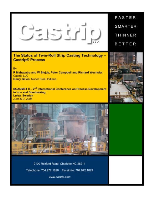
<strong>The</strong> <strong>Status</strong> <strong>of</strong> <strong>Twin</strong>-<strong>Roll</strong> <strong>Strip</strong> <strong>Casting</strong> <strong>Technology</strong> –<br />
<strong>Castrip</strong>® Process<br />
By<br />
R Mahapatra and W Blejde, Peter Campbell and Richard Wechsler,<br />
<strong>Castrip</strong> LLC<br />
Gerry Gillen, Nucor Steel Indiana<br />
SCANMET II – 2 nd International Conference on Process Development<br />
in Iron and Steelmaking<br />
Luleå, Sweden<br />
June 6-9, 2004<br />
2100 Rexford Road, Charlotte NC 28211<br />
Telephone: 704.972.1820 Facsimile: 704.972.1829<br />
www.castrip.com<br />
FASTER<br />
SMARTER<br />
THINNER<br />
BETTER
THE STATUS OF TWIN-ROLL STRIP CASTING TECHNOLOGY –<br />
CASTRIP ® PROCESS<br />
Rama Mahapatra 1 , Walter Blejde 1 , Gerry Gillen 2 , Peter Campbell 1 and Richard Wechsler 1<br />
1- <strong>Castrip</strong> LLC, 2100 Rexford Rd., Suite 420, Charlotte NC, 28226, USA<br />
2- Nucor Steel, 4537 South Nucor Road, Crawfordsville IN, 47933, USA<br />
Abstract<br />
<strong>The</strong> CASTRIP ® Process is aimed at producing steel sheet between 0.7 and 2 mm in thickness,<br />
at an annual capacity <strong>of</strong> 500,000 tonnes, utilizing twin-roll strip casting technology.<br />
Commissioning <strong>of</strong> the world’s first commercial strip caster for low-carbon steel production,<br />
utilizing CASTRIP technology, began in May 2002 at Nucor Steel, Crawfordsville, Indiana.<br />
Since that time, the plant has been ramping up production, improving product yield and<br />
quality, and selling steel sheet to the construction market. With many inherent advantages<br />
including low capital investment, reduced environmental impact, ability to cast thin, highvalue<br />
products, compact plant size and potential for new sheet products, CASTRIP<br />
technology is poised to create a new business model for the steel industry. This paper will<br />
report on progress made at the Nucor plant towards commercialization <strong>of</strong> this new<br />
technology.
Introduction<br />
<strong>The</strong> production <strong>of</strong> steel strip directly from liquid steel has been the dream <strong>of</strong> steel industry<br />
technologists for over 150 years. <strong>The</strong> world’s first commercial installation for direct casting<br />
<strong>of</strong> low-carbon steel sheet utilizing CASTRIP ® technology is undergoing production ramp-up<br />
at Nucor Steel’s plant in Crawfordsville, Indiana, U.S.A. Construction <strong>of</strong> the plant was<br />
initiated in February 2001 and the first ladle was delivered to the caster in May 2002. Since<br />
that time, Nucor Steel has been working with technology partners BlueScope Steel (formerly<br />
BHP Steel) and IHI (Ishikawajima-Harima Heavy Industries) to fully commercialize this<br />
exciting new technology for the direct production <strong>of</strong> steel sheet less than 2 mm in thickness.<br />
<strong>The</strong> CASTRIP process was jointly developed by BlueScope Steel and IHI beginning in 1989,<br />
under the code name Project ‘M’. Details <strong>of</strong> all the collaborative efforts expended towards<br />
development <strong>of</strong> CASTRIP ® technology over the last decade have been presented elsewhere<br />
[1-4]. In late 1999, Nucor Steel joined the effort and committed to build a full commercial<br />
plant at its existing steel facility in Crawfordsville IN [5-7]. At that time, <strong>Castrip</strong> LLC was<br />
created to make the technology and patents related to CASTRIP process available to third<br />
parties; <strong>Castrip</strong> LLC is owned jointly by BlueScope Steel (47.5%), IHI (5%) and Nucor<br />
(47.5%).<br />
CASTRIP process fundamentals<br />
Plant layout<br />
Figure 1 is a schematic representation <strong>of</strong> the general layout <strong>of</strong> the Nucor plant. Molten steel is<br />
transported to the CASTRIP facility from the existing Crawfordsville EAF, via rubber-tired<br />
carrier in 110-tonne ladles. Ladles are pre-treated in a LMF (ladle metallurgy furnace),<br />
located within the strip casting plant. <strong>The</strong> main components <strong>of</strong> the CASTRIP process are<br />
indicated in Figure 1, starting with the ladle turret and continuing to the coilers. A single<br />
rolling stand is capable <strong>of</strong> 50% reduction, however typical reductions are less than 30%.<br />
Included in the CASTRIP facility are work areas for refractories and roll preparation.<br />
155 m<br />
LMF<br />
ROLL<br />
PREP<br />
WATER<br />
TREATMENT<br />
P<br />
U<br />
L<br />
P<br />
I<br />
T<br />
135 m<br />
TURRET<br />
CASTER<br />
ROLLING<br />
MILL<br />
COOLING<br />
DOWN<br />
COILERS<br />
COIL<br />
STORAGE<br />
Figure 1. Schematic <strong>of</strong> Nucor CASTRIP plant layout.<br />
TUNDISH &<br />
REFRACTORY<br />
PREP<br />
ELECTRICAL<br />
SWITCH<br />
GEAR<br />
Ladle from EAF
A photo <strong>of</strong> the interior <strong>of</strong> the plant during operations is shown in Figure 2. A ladle <strong>of</strong> steel is<br />
visible at the top <strong>of</strong> the photo with the casting area immediately in front <strong>of</strong> and below the<br />
turret. <strong>The</strong> rolling stand is next (indicated by the “NUCOR” sign) with the run out table and<br />
cooling area thereafter. <strong>The</strong> structure straddling the run out table is a surface inspection<br />
station. <strong>The</strong> bottom right corner <strong>of</strong> the photo shows the shear and second pinch roll with the<br />
coilers just out <strong>of</strong> view.<br />
Figure 2. Photo <strong>of</strong> the interior <strong>of</strong> Nucor’s CASTRIP facility<br />
Process Description<br />
A schematic elevation <strong>of</strong> the strip-casting machine is shown in Figure 3. As can be seen, strip<br />
casting enables the elimination <strong>of</strong> intermediate process steps which exist in conventional strip<br />
production resulting in a process that is not only simpler, but in many respects more<br />
challenging from the process point <strong>of</strong> view. Molten steel is delivered from the ladle into the<br />
mould via a tundish followed by a metal distributor (or transition piece) and a set <strong>of</strong> delivery<br />
nozzles placed between the two casting rolls. After solidification on the casting rolls (0.5 m<br />
diameter), the strip exits through an inert gas chamber that is used to prevent the formation <strong>of</strong><br />
scale. <strong>The</strong> strip leaving the mill is cooled, cut to length by a shear and then coiled on one <strong>of</strong><br />
two coilers. <strong>The</strong> total line length is approximately 60 meters. <strong>The</strong> plant is fully automated<br />
requiring minimal operator intervention. Extensive use has been made <strong>of</strong> robotics.
Figure 3. Schematic elevation <strong>of</strong> Nucor’s CASTRIP plant.<br />
Plant experiences<br />
Plant Production<br />
Hot commissioning <strong>of</strong> the CASTRIP facility commenced on May 3, 2002 and to date more<br />
than 80,000 tonnes <strong>of</strong> UCS (Ultra-thin Cast <strong>Strip</strong>) material has been coiled. Since Jan 2003,<br />
the plant has been operating on a 24 hour cycle, 7 days per week. Quarterly production<br />
figures from the Nucor facility are shown in Figure 4. As indicated, progress at the plant was<br />
slow until mid 2003. During July 2003 a fundamental change was made in the process that<br />
provided improvements in yield, quality and throughput. Further increases in production by<br />
the plant are expected as Nucor increases capacity <strong>of</strong> the Crawfordsville EAF shop, heret<strong>of</strong>ore<br />
a limiting factor on steel available to cast.<br />
Quarterly Production (tons)<br />
30,000<br />
25,000<br />
20,000<br />
15,000<br />
10,000<br />
5,000<br />
-<br />
Q3 02<br />
Q4 02<br />
Q1 03<br />
Q2 03<br />
Figure 4. Production from Nucor CASTRIP facility<br />
Q3 03<br />
Q4 03<br />
Q1 04 (proj.)
Current development focus<br />
During ramp-up <strong>of</strong> the CASTRIP facility at Crawfordsville, the main focus has been to cast<br />
low carbon steel sheet (0.04 to 0.06% carbon), at a width <strong>of</strong> 1345 mm. Owing to the unique<br />
relationship among casting speed, solidification rate and casting thickness, the twin-roll<br />
casting process is ideally suited for production <strong>of</strong> thin strip. Machine throughput in strip<br />
casting increases with decreasing cast strip thickness, unlike conventional strip production<br />
processes where productivity declines. Thus, the aim thickness for casting has tended<br />
downwards during the commissioning phase and now stands at 1.6 mm or less. This equates<br />
to a casting speed <strong>of</strong> 80 m/min with an annualized rate <strong>of</strong> more than 500,000 tonnes. Current<br />
operations reduce the thickness <strong>of</strong> the cast material further by rolling in the in-line mill<br />
between 10 to 15%. Thus, the bulk <strong>of</strong> the UCS products have been in the thickness range <strong>of</strong><br />
1.3 mm to 1.6 mm.<br />
Downstream processing <strong>of</strong> the material, prior to sale to the market, has included some <strong>of</strong> the<br />
following steps: skin passing, edge trimming, pickling, cold rolling and galvanizing.<br />
Key Process Milestones attained<br />
In addition to routine production <strong>of</strong> strip thicknesses in the range <strong>of</strong> 1.3 to 1.6 mm, a number<br />
<strong>of</strong> other milestones have been attained during the commissioning and ramp-up <strong>of</strong> the process;<br />
these include:<br />
1. <strong>The</strong> plant has repeatedly demonstrated the capability <strong>of</strong> sequence casting 3 or more<br />
consecutive ladles (>330 tonnes). This is a critical factor for process economics<br />
2. Final strip thickness <strong>of</strong> as low as 1.1 mm has been produced and successfully<br />
processed.<br />
3. Hourly production rates <strong>of</strong> 60 tonnes/hr/m have been consistently achieved. This<br />
indicates an annual throughput <strong>of</strong> >500,000 tonnes<br />
4. Castability <strong>of</strong> low carbon steel grades with higher copper levels (up to 0.5%) has been<br />
demonstrated. Possible benefits from lower incoming scrap quality without<br />
degenerated product properties are foreseen.<br />
5. Despite a clear focus on low-carbon structural grades, successful casting trials with<br />
stainless (409), medium carbon (0.25), higher phosphorous (0.1%) and electrical steels<br />
have been conducted.<br />
Product quality<br />
Satisfactory attainment <strong>of</strong> strip quality attributes can only be produced through careful control<br />
<strong>of</strong> metal delivery, mould heat extraction & solidification, mould thermo-mechanical behavior,<br />
edge technology, microstructure evolution and in-line hot rolling. Process fundamentals<br />
associated with these aspects have been reported elsewhere [3]. Descriptions <strong>of</strong> some <strong>of</strong> the<br />
product attributes achieved to date at the Crawfordsville plant are presented in this section.<br />
Surface quality<br />
<strong>Strip</strong> surface texture<br />
<strong>Strip</strong> surface finish has been characterized using a surface Pr<strong>of</strong>ilometer (Rank Taylor Hobson<br />
Series 120). This instrument uses a diamond tip stylus (tip radius 2 mm) with a resolution <strong>of</strong>
32 nm. Table 1 compares the surface roughness measurements obtained from as-cast UCS<br />
material with strip obtained from conventional hot strip mill. <strong>The</strong> roughness <strong>of</strong> the as-cast<br />
strip is between 2 to 3 µm in comparison to 1 to 1.5 µm for conventional hot strip mill<br />
product. Previous work during the development <strong>of</strong> the process at the Project M plant in<br />
Australia had shown that surfaces smoother than conventional hot strip mill material can be<br />
obtained with the use <strong>of</strong> in-line mill with roll bite lubrication [2] and this development is<br />
currently underway at Crawfordsville.<br />
Table 1: Comparison <strong>of</strong> strip surface texture – as-cast UCS strip vs. conventional hot rolled<br />
strip<br />
Location Parameter As-cast UCS Conventional<br />
hot strip<br />
Top surface Ra (µm) 2.8 1.33<br />
RzDin (µm) 18.6 9.7<br />
S (µm) 101.2 56.6<br />
Bottom surface Ra (µm) 2.2 1.11<br />
RzDin (µm) 12.5 9.2<br />
S (µm) 69.8 60.0<br />
Scale<br />
One <strong>of</strong> the inherent advantages <strong>of</strong> strip casting is the opportunity to control and possibly<br />
prevent the formation <strong>of</strong> surface scale. This is due to the ability to contain the strip in a<br />
protective atmosphere immediately following casting and into the rolling mill. Although the<br />
work on atmosphere control is preliminary at this stage, scale formed during the process has<br />
been measured via metallographic examination. Figure 5 compares the scale levels <strong>of</strong> as-cast<br />
UCS with that <strong>of</strong> a conventional hot strip material. As can be seen, the thickness <strong>of</strong> the scale<br />
formed on the surface <strong>of</strong> the as-cast UCS is similar to that <strong>of</strong> the hot strip material, i.e. 4 to 8<br />
µm.<br />
(a) (b)<br />
Figure 5. Micrographs showing scale levels on: (a) as-cast UCS (b) conventional hot rolled<br />
strip (note that darker region on the top in both micrographs is the sample mount)<br />
Scale levels on the strip have a significant impact on process economics. <strong>Strip</strong> casting <strong>of</strong>fers<br />
significant potential to further reduce scale levels by effective shrouding and strip temperature<br />
control. Future developments will concentrate on producing scale-free surface and thereby<br />
eliminating pickling, which could lead to a significant reduction in operating costs.<br />
Internal Quality<br />
Scale layer<br />
Steel substrate
Solidification microstructure<br />
Figure 6 shows the as-cast microstructure <strong>of</strong> UCS material. As can be seen, the structure is<br />
characterized by a fine dendritic solidification structure, which is consistent with previous<br />
observations [8]. <strong>The</strong> straight centerline, apparent in the meeting <strong>of</strong> the dendrites from either<br />
strip surface, is a reflection <strong>of</strong> uniform solidification on both casting rolls.<br />
Figure 6. As-cast UCS solidification microstructure.<br />
Segregation<br />
Segregation levels through the thickness <strong>of</strong> the strip have been characterized with<br />
“Quantitative elemental x-rap mapping”. A typical x-ray map for Phosphorous, presented in<br />
Figure 7, shows uniform levels thorough the strip without any notable segregation. This is a<br />
consequence <strong>of</strong> the solidification rates prevalent rates in strip casting, which do not allow<br />
macro segregation <strong>of</strong> residual elements to occur. In fact, solidification during the CASTRIP<br />
process is complete in 0.15 seconds at an average shell cooling rate <strong>of</strong> approximately 1700<br />
°C/s.<br />
Figure 7: Quantitative full thickness X-ray map <strong>of</strong> Phosphorous from as-cast UCS material<br />
Internal soundness<br />
Radiography was used to assess the internal soundness <strong>of</strong> the strip, i.e. analyze for porosity.<br />
Figure 8 is a radiograph <strong>of</strong> in-line hot rolled UCS subjected to less than 15% reduction. As<br />
can be seen, there are no voids/porosity present in the material (note that internal voids would<br />
appear as white spots on the radiograph). A major contributing factor to porosity is the degree
<strong>of</strong> non-uniformity in the solidification front during strip casting. Poor control over initial<br />
solidification combined with the rapid shell growth inherent in strip casting can lead to<br />
problems both on the strip surface and in the interior.<br />
Figure 8 – Radiography <strong>of</strong> UCS material (in-line hot rolled)<br />
Inclusion composition and size distribution<br />
An assessment <strong>of</strong> inclusions present in strip produced via the CASTRIP process was carried<br />
out using a Cameca SX50 Micro Probe Analyzer. <strong>The</strong> deoxidation practice utilized at the<br />
CASTRIP plant relies on silicon and manganese as the killing agents. Micro probe analysis<br />
showed the presence <strong>of</strong> fine aluminum-manganese-silicate type <strong>of</strong> inclusions. Figure 8<br />
compares the size distribution <strong>of</strong> inclusions found in as-cast UCS and conventional hot rolled<br />
strip. <strong>The</strong> figure indicates that inclusions are typically 2 to 5 µm in size for UCS, which is<br />
similar to that <strong>of</strong> hot strip samples, despite the fact that no hot reduction has occurred. Finer<br />
inclusions in strip cast material are a direct outcome <strong>of</strong> rapid solidification, which reduces the<br />
time available for inclusion agglomeration and growth.<br />
Frequency<br />
35<br />
30<br />
25<br />
20<br />
15<br />
10<br />
5<br />
0<br />
0<br />
2<br />
4<br />
6<br />
8<br />
10<br />
12<br />
14<br />
Inclusion Size (microns)<br />
(a)<br />
16<br />
>17<br />
Frequency<br />
35<br />
30<br />
25<br />
20<br />
15<br />
10<br />
5<br />
0<br />
0<br />
2<br />
4<br />
6<br />
8<br />
10<br />
12<br />
14<br />
16<br />
>17<br />
Inclusion Size (microns)<br />
(b)
Figure 9. Comparison <strong>of</strong> inclusion size distribution measured in (a) as-cast UCS and (b)<br />
conventional hot rolled strip.<br />
Edge Quality<br />
Achievement <strong>of</strong> good edges is one <strong>of</strong> the greatest challenges in strip casting. <strong>The</strong> region <strong>of</strong> the<br />
side dam in direct contact with the roll is cooled dramatically making this area more prone to<br />
steel freezing and thus skull formation. This can result in poor edge quality and in some cases<br />
cause severe operational problems. Effective control <strong>of</strong> metal flow and solidification in this<br />
region is fundamental to the production <strong>of</strong> good edges. As-cast coils with good edges are<br />
routinely produced and an example <strong>of</strong> a coil edge is shown in Figure 10.<br />
Figure 10. Photograph <strong>of</strong> an untrimmed, as-cast UCS coil edge.<br />
<strong>Strip</strong> Pr<strong>of</strong>ile<br />
<strong>Strip</strong> thickness is continuously measured throughout the cast using two on-line, X-ray gauges.<br />
<strong>The</strong> scanning X-ray device, which is located before the hot rolling stand is dedicated to<br />
measuring the strip pr<strong>of</strong>ile, and the second device is used to measure the centerline thickness<br />
after the mill. Figure 11 is an example <strong>of</strong> a typical cast strip pr<strong>of</strong>ile (averaged over a coil).<br />
<strong>Strip</strong> crown measured at 40 mm from the edge is about 75 um. Work is currently underway to<br />
reduce the strip crown.
<strong>Strip</strong> thickness (mm)<br />
1.6<br />
1.5<br />
1.4<br />
1.3<br />
1.2<br />
1.1<br />
0 200 400 600<br />
Width (mm)<br />
800 1000 1200<br />
Figure 11: Typical as-cast UCS strip pr<strong>of</strong>ile<br />
<strong>Strip</strong> microstructures and mechanical properties<br />
UCS microstructures<br />
Microstructure evolution in strip casting is fundamentally coupled to the solidification<br />
process. <strong>The</strong> nucleation density during solidification can pr<strong>of</strong>oundly influence the austenite<br />
grain size and thus, subsequent ferritic microstructures [4]. Under normal cooling conditions,<br />
the microstructure <strong>of</strong> the as-cast material is a mixture <strong>of</strong> polygonal ferrite and low<br />
temperature transformation products such as acicular ferrite (see Figure 12).<br />
Figure 13. Typical as-cast UCS microstructure.<br />
UCS mechanical properties<br />
Typical mechanical properties <strong>of</strong> UCS in-line rolled material produced at the Nucor<br />
CASTRIP facility, are summarized in Table 2. A majority <strong>of</strong> the cast material today has been<br />
produced to meet ASTM A1011M specification. As can be seen from Table 2, UCS material
exceeds the requirement for Grade 275, according to the specification. Grade 275 is a<br />
common low carbon structural grade in the U.S markets for application in construction and<br />
manufacturing markets.<br />
Table 2. Properties <strong>of</strong> typical UCS material produced by the CASTRIP process. <strong>The</strong> material<br />
conforms to ASTM A1011M SS Grade 275.<br />
ASTM A1011 –<br />
Grade 275 minimum<br />
UCS (rolled) –<br />
typical<br />
Conclusions and Next Steps<br />
Yield Strength Tensile Strength Elongation<br />
(MPa)<br />
(MPa)<br />
(%)<br />
275 380 15<br />
315 420 24<br />
<strong>The</strong> start-up <strong>of</strong> the CASTRIP process at Nucor’s Crawfordsville plant marks the first<br />
commercial strip casting installation for the production <strong>of</strong> plain-carbon steels. Commissioning<br />
has been proceeding well, although not without the normal challenges <strong>of</strong> a new technology.<br />
To date, the CASTRIP process has demonstrated the following key strip casting milestones:<br />
Product quality <strong>of</strong> UCS from the CASTRIP process has been shown to be suitable as a<br />
direct substitute for hot rolled coil as well as feed for cold rolling operations.<br />
<strong>Strip</strong> thicknesses as low as 1.1 mm have been produced. <strong>The</strong> majority <strong>of</strong> UCS<br />
produced has been between 1.3 and 1.6 mm<br />
UCS product has been galvanized without cold rolling, with properties suitable for<br />
construction applications.<br />
Sequence lengths <strong>of</strong> 3 ladles and greater (> 330 tonnes) have been regularly achieved.<br />
This is a critical factor for process economics.<br />
Operating costs per tonne are constantly being reduced as throughput continues to<br />
climb. Critical cost elements (refractories, casting rolls) are performing at expected<br />
levels.<br />
In addition to low-carbon grades, trial casts have been performed on stainless and<br />
other carbon grades, with promising results.<br />
Still to be confirmed for the technology are the overall conversion costs and life <strong>of</strong> other<br />
critical components. This information will be obtained as the plant works its way towards full<br />
operating rates, over the next year or so.<br />
REFERENCES<br />
[1] W. Blejde, R. Mahapatra and H. Fukase, “Recent Developments in Project M – <strong>The</strong><br />
Joint Development <strong>of</strong> Low carbon Steel strip <strong>Casting</strong> by BHP and IHI”, International<br />
Conference on New Developments on metallurgical Process <strong>Technology</strong>, METEC<br />
Congress, June 1999, 176-181.<br />
[2] W. Blejde, R. Mahapatra, H. Fukase, “Development <strong>of</strong> Low carbon Thin <strong>Strip</strong><br />
production at Project M”, Iron and Steelmaker, Vol. 27, No 4, 2000, 29-33.
[3] W. Blejde, R. Mahapatra and H. Fukase: “Application <strong>of</strong> Fundamental Research at<br />
Project M”, <strong>The</strong> Belton Memorial Symposium Proceedings, 2000, 253-261.<br />
[4] K. Mukunthan et al., “Evolution <strong>of</strong> microstructures and product opportunities in low<br />
carbon strip casting”, <strong>The</strong> Brimacombe Memorial Symposium Proceedings, 2000, 421-<br />
437.<br />
[5] P. Campbell and R. Wechsler, “<strong>The</strong> CASTRIP ® Process: A revolutionary casting<br />
technology, an exciting opportunity for unique steel products or a new model for steel<br />
Micro-Mills?” Proceedings <strong>of</strong> Gerald Heffernan International Symposium on Innovative<br />
Technologies for Steel and other Materials, 2001, 201-214.<br />
[6] R. Wechsler and P. Campbell, “<strong>The</strong> First Commercial Plant for Carbon Steel <strong>Strip</strong><br />
<strong>Casting</strong> at Crawfordsville”, Dr. Manfred Wolf Symposium, 2002, 70-79.<br />
[7] P. Campbell et al., “Start-up and Operating Experience <strong>of</strong> the CASTRIP ® Process at<br />
Nucor Crawfordsville” ISS Tech 2003 Conference Proceedings, 2003, 451-460.<br />
[8] A. Cramb, “<strong>Strip</strong> <strong>Casting</strong> <strong>of</strong> Steels: Current <strong>Status</strong> and Fundamental Aspects”,<br />
Proceedings <strong>of</strong> the International Symposium on Near-Net-Shape <strong>Casting</strong> in the Mini-<br />
Mills, 1995, 355-372.