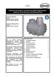
Anleitung für Einbau und Wartung GRAF Trinkwasser
Anleitung für Einbau und Wartung GRAF Trinkwasser
Anleitung für Einbau und Wartung GRAF Trinkwasser

Create successful ePaper yourself
Turn your PDF publications into a flip-book with our unique Google optimized e-Paper software.
info@graf-online.de<br />
www.graf-online.de<br />
<strong>Anleitung</strong> <strong>für</strong> <strong>Einbau</strong> <strong>und</strong> <strong>Wartung</strong> <strong>GRAF</strong> <strong>Trinkwasser</strong>-<br />
Nachspeisung SILENTIO<br />
SILENTIO 15/4<br />
Art. Nr. 350209<br />
SILENTIO 25/4<br />
Art. Nr. 350210<br />
SILENTIO 15/4 mit Ladepumpe<br />
Art. Nr. 350211<br />
SILENTIO 25/4 mit Ladepumpe<br />
Art. Nr. 350212<br />
Die in dieser <strong>Anleitung</strong><br />
beschriebenen Punkte sind unbedingt<br />
zu beachten. Bei Nichtbeachtung<br />
erlischt jeglicher<br />
Garantieanspruch. Für alle über<br />
<strong>GRAF</strong> bezogenen Zusatzartikel<br />
erhalten Sie separate in der<br />
Transportverpackung beiliegende<br />
<strong>Einbau</strong>anleitungen.<br />
Fehlende <strong>Anleitung</strong>en sind umgehend<br />
bei uns anzufordern.<br />
Eine Überprüfung der Komponenten<br />
auf eventuelle Beschädigungen<br />
hat unbedingt vor der<br />
Montage bzw. Installation zu<br />
erfolgen.<br />
Der <strong>Einbau</strong> ist von einer Fachfirma<br />
durchzuführen.<br />
Inhaltsübersicht<br />
1. ALLGEMEINE HINWEISE 2<br />
1.1 Sicherheit 2<br />
1.2 Kennzeichnungspflicht 2<br />
2. EINSATZBEREICHE 2<br />
3. TECHNISCHE DATEN 3<br />
3.1 Abmessungen <strong>und</strong> Gewicht 3<br />
3.2 Steuerung 4<br />
3.3 Schwimmerventil 4<br />
3.4 3-Wege Umschaltventil 4<br />
3.5 Druck- <strong>und</strong> Strömungswächter „Controlmatic“ 4<br />
3.6 Pumpe 4<br />
3. TECHNISCHE DATEN 5<br />
4. MONTAGE UND EINBAU 6<br />
4.1 Wandmontage 6<br />
4.2 Anschluss Notüberlauf 7<br />
4.3 <strong>Trinkwasser</strong>anschluss 7<br />
4.4 Anschluss Saugleitung 8<br />
4.5 Anschluss Druckleitung 8<br />
4.6 Anschluss Datenleitung <strong>und</strong> Sensorik 9<br />
4.7 Anschluss Zusatzpumpe <strong>und</strong> Magnetventil <strong>für</strong><br />
Opticlean (optional) 9<br />
5. INBETRIEBNAHME 9<br />
6. WARTUNG UND PFLEGE 10<br />
6.1 <strong>Wartung</strong> 10<br />
6.2 Pflege 10<br />
7. STÖRUNG UND ABHILFEMAßNAHMEN 11<br />
8. SERVICEADRESSE 12<br />
1 / 24<br />
Deutsch<br />
English
1.1 Sicherheit<br />
info@graf-online.de<br />
www.graf-online.de<br />
1. Allgemeine Hinweise<br />
Bei sämtlichen Arbeiten sind die einschlägigen Unfallverhütungsvorschriften nach BGV C22 zu beachten.<br />
Des Weiteren sind bei <strong>Einbau</strong>, Montage, <strong>Wartung</strong>, Reparatur usw. die in Frage kommenden Vorschriften<br />
<strong>und</strong> Normen zu berücksichtigen. Hinweise hierzu finden Sie in den dazugehörigen Abschnitten dieser<br />
<strong>Anleitung</strong>.<br />
Die Installation der Anlage bzw. einzelner Anlagenteile muss von qualifizierten Fachleuten durchgeführt<br />
werden.<br />
Bei sämtlichen Arbeiten an der Anlage bzw. Anlagenteilen ist immer die Gesamtanlage außer Betrieb zu<br />
setzen <strong>und</strong> gegen unbefugtes Wiedereinschalten zu sichern.<br />
Die Firma <strong>GRAF</strong> bietet ein umfangreiches Sortiment an Zubehörteilen, die alle aufeinander abgestimmt<br />
sind <strong>und</strong> zu kompletten Systemen ausgebaut werden können. Die Verwendung anderer Zubehörteile kann<br />
dazu führen, dass die Funktionsfähigkeit der Anlage beeinträchtigt <strong>und</strong> die Haftung <strong>für</strong> daraus entstandene<br />
Schäden aufgehoben wird.<br />
Bestimmte Anlagenteile stehen unter Spannung <strong>und</strong> dürfen nicht geöffnet werden. Arbeiten an elektrischen<br />
Einrichtungen dürfen nur von Elektrofachkräften durchgeführt werden.<br />
Alle Elektrokabel <strong>und</strong> Anschlüsse müssen sich in einem einwandfreien Zustand befinden. Bei<br />
Beschädigungen darf die Anlage auf keinen Fall in Betrieb genommen werden.<br />
Im Schadensfall kann Wasser aus der Anlage austreten. Das Wasser ist beispielsweise durch Installation<br />
eines Bodenablaufs abzuführen.<br />
Bei unzureichender Befestigung bzw. Montage kann die Anlage herabfallen, es ist <strong>für</strong> eine ausreichende<br />
Tragkraft der Wand bzw. Halterung zu sorgen.<br />
1.2 Kennzeichnungspflicht<br />
Das Betriebswasser ist nicht zum Verzehr <strong>und</strong> zur Körperhygiene geeignet.<br />
Alle Leitungen <strong>und</strong> Entnahmestellen von Brauchwasser sind mit den Worten „Kein <strong>Trinkwasser</strong>“ schriftlich<br />
oder bildlich zu kennzeichnen (DIN 1988 Teil 2, Abs. 3.3.2.) um auch nach Jahren eine irrtümliche<br />
Verbindung mit dem <strong>Trinkwasser</strong>netz zu vermeiden. Auch bei korrekter Kennzeichnung kann es noch zu<br />
Verwechslungen kommen, z.B. durch Kinder. Deshalb müssen alle Brauchwasser – Zapfstellen mit<br />
Ventilen mit Kindersicherung installiert werden.<br />
Die Anlage hat keinen Einfluss auf die Qualität des Betriebswassers.<br />
2. Einsatzbereiche<br />
Die <strong>GRAF</strong> <strong>Trinkwasser</strong>nachspeisung SILENTIO ist eine Mikroprozessorgesteuerte Schalt-zentrale <strong>für</strong><br />
Regenwasser-Nutzungsanlagen. Sie dient der Betriebswasserversorgung von Ein- <strong>und</strong> kleineren<br />
Mehrfamilienhäusern. Durch die automatische, bedarfsgerechte Nachspeisung mit <strong>Trinkwasser</strong> ist auch bei<br />
leerem Regenwasserbehälter eine Betriebswasserversorgung gewährleistet.<br />
Betriebswasser kann zum Garten gießen, <strong>für</strong> die Toilettenspülung, zum Wäsche waschen <strong>und</strong> als<br />
Putzwasser verwendet werden.<br />
Die <strong>GRAF</strong> <strong>Trinkwasser</strong>-Nachspeisung SILENTIO ist zur Montage in frostgeschützten, überflutungssicheren<br />
<strong>und</strong> trockenen Räumen vorgesehen. Weitere Angaben zur Anlagenauslegung, Montage<br />
<strong>und</strong> Bedienung entnehmen Sie den folgenden Kapiteln.<br />
2 / 24
3.1 Abmessungen <strong>und</strong> Gewicht<br />
Gewicht: ca. 26 kg<br />
info@graf-online.de<br />
www.graf-online.de<br />
3. Technische Daten<br />
3 / 24
3.2 Steuerung<br />
info@graf-online.de<br />
www.graf-online.de<br />
3. Technische Daten<br />
Die technischen Daten entnehmen Sie bitte der beiliegenden Bedienungsanleitung.<br />
3.3 Schwimmerventil<br />
Betriebstemperatur 30°C max.<br />
Betriebsdruck<br />
Druckfluss max. 1,7 m 3 /h<br />
Anschlüsse<br />
3<br />
/4“ AG<br />
3.4 3-Wege Umschaltventil<br />
Spannung / Frequenz 230 V / 50Hz<br />
Leistung 6 W (bei Ventilbewegung)<br />
Durchfluss max. 16 m 3 /h<br />
Öffnungszeit ca. 10 sek<br />
Schließzeit ca. 5 sek<br />
Druck max. 10 bar<br />
Zulässiger Differenzdruck 0,7 bar<br />
3.5 Druck- <strong>und</strong> Strömungswächter „Controlmatic“<br />
Spannung / Frequenz 230 V / 50 Hz<br />
Schutzklasse IP 44<br />
Durchflussmenge max. 10 m 3 /h<br />
Durchflussmenge min. 0,1 m 3 /h<br />
Betriebsdruck max. 10 bar<br />
Einschaltdruck min. 1,5 bar<br />
Einschaltdruck max. 2,6 bar<br />
0,3 – 4,5 bar (bei zu starkem Wasserdruck muss ein Druckminderer<br />
eingebaut werden)<br />
Wiederinbetriebnahme nach Trockenlauf der Pumpe durch Betätigung der „RESET“ Taste möglich.<br />
Sind in der Anlage Druckstöße durch schnell schließende Armaturen (z. B. Magnetventile in<br />
Hochdruckreinigern) zu erwarten, halten Sie bitte Rücksprache mit Fa. <strong>GRAF</strong>.<br />
3.6 Pumpe<br />
Antrieb<br />
3.6.1 SILENTIO 15/4<br />
Leistungsaufnahme 660 W<br />
Förderhöhe max. 35 m<br />
Druck max. 3,5 bar<br />
Einphasen-Wechselstrommotor 220-240 V / 50 Hz mit eingebautem<br />
Überlastschutz, IP 44, Isolationsklasse F.<br />
Fördermenge max. 3600 l/h (siehe auch Diagramm 2)<br />
Saughöhe max. 3 m<br />
Sauglänge max. 15 m<br />
Bezüglich Saughöhe als Funktion der Sauglänge siehe auch Diagramm 1.<br />
4 / 24
3.6.2 SILENTIO 25/4<br />
S<br />
a<br />
u<br />
g<br />
l<br />
ä<br />
n<br />
g<br />
e<br />
20<br />
18<br />
16<br />
14<br />
12<br />
10<br />
8<br />
6<br />
m 4<br />
2<br />
F<br />
ö<br />
r<br />
d<br />
e<br />
r<br />
h<br />
ö<br />
h<br />
e<br />
60<br />
50<br />
40<br />
30<br />
20<br />
10<br />
m<br />
info@graf-online.de<br />
www.graf-online.de<br />
Saughöhe als Funktion der Sauglänge<br />
funktioniert<br />
0 1 2 3<br />
Saughöhe m<br />
Superinox 25/4<br />
Superinox 15/4<br />
3. Technische Daten<br />
Leistungsaufnahme 800 W<br />
Förderhöhe max. 43 m<br />
Druck max. 4,3 bar<br />
Fördermenge max. 4200 l/h (siehe Diagramm 2)<br />
Saughöhe max. 3 m<br />
Sauglänge 15 m<br />
Bezüglich Saughöhe als Funktion der Sauglänge siehe auch Diagramm 1.<br />
Fördermenge in Abhängigkeit zur Förderhöhe<br />
0 1 2 3 4 5 6<br />
Fördermenge m³/h<br />
5 / 24<br />
funktioniert nicht<br />
(Tauchpumpe einsetzen)<br />
4 5 6
info@graf-online.de<br />
www.graf-online.de<br />
4. Montage <strong>und</strong> <strong>Einbau</strong><br />
Die <strong>GRAF</strong> <strong>Trinkwasser</strong>-Nachspeisung SILENTIO aus der Transportverpackung nehmen, im gleichen<br />
Karton befindet sich auch das Zubehör. Die gesamte Anlage sofort auf eventuelle Beschädigungen<br />
überprüfen. Beschädigungen müssen vor der Montage gemeldet werden.<br />
4.1 Wandmontage<br />
Die <strong>GRAF</strong> <strong>Trinkwasser</strong>-Nachspeisung SILENTIO ist zur Aufhängung (oberhalb der Rückstauebene) in<br />
frostgeschützten, überflutungssicheren <strong>und</strong> trockenen Räumen vorgesehen.<br />
Bei der Standortwahl ist zu berücksichtigen, dass <strong>für</strong> eventuelle Einstell- <strong>und</strong> <strong>Wartung</strong>sarbeiten oberhalb<br />
der Anlage noch ca. 50 cm Platz zur Verfügung stehen muss. Die vorgesehene Wand muss geeignet sein,<br />
das Anlagengewicht im gefüllten Zustand von ca. 45 kg, zu tragen.<br />
Die zu bohrenden Punkte laut Bohrbild an der gewünschten Wand einzeichnen <strong>und</strong> mit einem 12er Bohrer<br />
die Befestigungslöcher mit einer Tiefe von ca. 60 mm bohren. Die beiliegenden Dübel einsetzen <strong>und</strong> die<br />
Stehbolzen mit ca. 8 mm Überstand einschrauben. Auf die oberen Stehbolzen werden die beiden<br />
Gummipuffer mit Innen/Außengewinde, auf den unteren der Gummipuffer mit 2 x Innengewinde<br />
aufgeschraubt.<br />
6 / 24
4.2 Anschluss Notüberlauf<br />
info@graf-online.de<br />
www.graf-online.de<br />
4. Montage <strong>und</strong> <strong>Einbau</strong><br />
Der Notüberlauf wird mit handelsüblichem DN 70 Rohren hergestellt. In Räumen mit Bodenablauf ist es<br />
ausreichend das überlaufende Wasser ohne Anschluss an die Kanalisation aus der Nachspeiseeinheit<br />
herauslaufen zu lassen, da im Normalbetrieb kein Wasser austritt. Ist kein Bodenablauf vorhanden, wird<br />
der Notüberlauf an das Abwassernetz angeschlossen. Bei Veränderungen am Notüberlauf erlischt die<br />
DVGW-Zulassung, eine einwandfreie Funktion kann dann nicht mehr garantiert werden.<br />
4.3 <strong>Trinkwasser</strong>anschluss<br />
Zur Verbindung des Schwimmerventils mit dem <strong>Trinkwasser</strong>netz empfehlen wir die Installation mit einem<br />
¾“ Panzerschlauch. Beim Anschließen der Frischwasserzuleitung muss ein verdrehen des Ventils<br />
unbedingt verhindert werden, da eine einwandfreie Funktion ansonsten nicht gewährleistet ist. Ein<br />
zusätzliches Absperrventil erleichtert zukünftige <strong>Wartung</strong>sarbeiten.<br />
Vor der Installation muss die <strong>Trinkwasser</strong>leitung gut durchgespült werden. Ein bauseits zu montierender<br />
Feinfilter garantiert eine langfristige Funktion des Schwimmerventils <strong>und</strong> des 3-Wege Umschaltventils.<br />
Achtung:<br />
Leitungsdruck Stadtnetz<br />
max. 0,3 – 4,5 bar!<br />
7 / 24
4.4 Anschluss Saugleitung<br />
info@graf-online.de<br />
www.graf-online.de<br />
4. Montage <strong>und</strong> <strong>Einbau</strong><br />
Die 1“ Saugleitung wird in einem Leerrohr stetig steigend, ohne Durchbiegungen zum Installationsort der<br />
<strong>Trinkwasser</strong>nachspeisung geführt. Ist dies nicht möglich, ist an der höchsten Stelle der Saugleitung ein<br />
Entlüftungsventil zu installieren.<br />
Der Anschluss an die Nachspeiseeinheit SILENTIO erfolgt oberhalb des 3-Wege-Umschaltventils am<br />
90° Messingbogen mittels des beiliegenden 1“ Panzerschlauches. Die Installation eines Absperrhahnes in<br />
der Saugleitung erleichtert eventuelle <strong>Wartung</strong>sarbeiten.<br />
4.5 Anschluss Druckleitung<br />
Der Anschluss der Druckleitung erfolgt am 90° Messingbogen am Druck- <strong>und</strong> Strömungswächter mittels<br />
des zweiten beiliegenden 1“ Panzerschlauches, dieser wird nach oben aus dem Gerät herausgeführt. Die<br />
weitere Installation zu den einzelnen Verbrauchern erfolgt bauseits mit handelsüblichem Installationsrohr<br />
(kein Kupferrohr verwenden). Ein Absperrhahn in der Druckleitung erleichtert eventuelle <strong>Wartung</strong>sabreiten.<br />
8 / 24
4.6 Anschluss Datenleitung <strong>und</strong> Sensorik<br />
info@graf-online.de<br />
www.graf-online.de<br />
4. Montage <strong>und</strong> <strong>Einbau</strong><br />
Die Datenleitung wird vom Erdtank durch das Leerrohr zur Nachspeisung SILENTIO verlegt <strong>und</strong> am freien<br />
Chinchstecker angeschlossen. Die Sensorik im Behälter wird laut der beiliegenden Installationsanleitung<br />
<strong>für</strong> die Steuerung angeschlossen.<br />
4.7 Anschluss Zusatzpumpe <strong>und</strong> Magnetventil <strong>für</strong> Opticlean (optional)<br />
Das Magnetventil zur automatischen Ansteuerung der Reinigungseinheit Opticlean sowie eine mögliche<br />
Zusatzpumpe können über die Mikroprozessorsteuerung geschaltet werden. Eine entsprechende<br />
Montageanleitung finden Sie in der beiliegenden Installationsanleitung <strong>für</strong> die Steuerung. Benutzen Sie<br />
ausschließlich von <strong>GRAF</strong> freigegebene Ventile <strong>und</strong> Pumpen, ansonsten kann es zu Schäden in der<br />
Elektronik der Steuerung kommen.<br />
5. Inbetriebnahme<br />
Vor Inbetriebnahme der Anlage müssen alle zu- <strong>und</strong> abführenden Leitungen durchgespült werden.<br />
Teilchen > 0,2 mm können zu schweren Schäden an der Pumpe <strong>und</strong> anderer Bauteile führen.<br />
Nehmen Sie die Pumpe niemals trocken in Betrieb!<br />
Schrauben Sie den Einfüllstutzen am Pumpengehäuse auf <strong>und</strong> füllen Sie den Pumpenkörper mit Wasser.<br />
Anschließend wird die Saugleitung ebenfalls mit Wasser befüllt. Hierzu wird am Zisternen-seitigen Ende<br />
ein Schlauch an die Saugleitung (Saugkorb entfernen) angeschlossen <strong>und</strong> ein Verbraucher im Haus<br />
geöffnet. Stellen Sie sicher, dass das rote 3-Wege-Ventil auf Automatik [A] steht. Durch öffnen des<br />
Zulaufventils am Befüllschlauch die gesamte Anlage befüllen, bis am geöffneten Verbraucher Wasser<br />
blasenfrei austritt. Mit dieser Vorgehensweise wird die Anlage zuverlässig entlüftet <strong>und</strong> ist sofort<br />
betriebsbereit. Jetzt den Netzstecker der Steuerung in eine Steckdose (230 V / Absicherung 16 A träge)<br />
einstecken, die Anlage läuft sofort an. Sollte die Pumpe nicht anlaufen bzw. nach kurzer Zeit wieder<br />
ausgehen ist der „Reset Knopf“ am Controlmatic zu drücken. Dieser Vorgang ist so lange zu wiederholen,<br />
bis am Verbraucher das Wasser blasenfrei austritt, anschließend den Verbraucher schließen, die Pumpe<br />
erreicht ihren maximalen Druck <strong>und</strong> schaltet automatisch ab.<br />
Ist ein befüllen der Saugleitung wie oben beschrieben nicht möglich, kann diese auch vom Installationsort<br />
der SILENTIO befüllt werden, dabei muss das Fußventil der Saugleitung im Behälter geöffnet werden. Die<br />
Befüllung muss so lange erfolgen, bis am zisternenseitigen<br />
Ende Wasser austritt. Anschließend die Anlage wie oben beschrieben in Betrieb nehmen.<br />
Zum Abschluss der Inbetriebnahme wird der <strong>Trinkwasser</strong>zulauf zum Nachspeisebehälter geöffnet.<br />
Dadurch füllt sich der Behälter, bevor das Wasser durch den Überlauf abfließt muss das Schwimmerventil<br />
den Zulauf verschließen. Ist dies nicht der Fall muss das Ventil durch nachjustieren des<br />
Styroporschwimmers eingestellt werden.<br />
9 / 24
6.1 <strong>Wartung</strong><br />
info@graf-online.de<br />
www.graf-online.de<br />
6. <strong>Wartung</strong> <strong>und</strong> Pflege<br />
Die komplette Anlage muss in regelmäßigen Abständen (ca. alle 3 – 4 Monate) gewartet werden. Bei jeder<br />
<strong>Wartung</strong> sind alle Schraubverbindungen auf Dichtheit zu prüfen. Des Weiteren sollte der Sitz <strong>und</strong> die<br />
Funktion des Schwimmerventils im Nachspeisebehälter kontrolliert werden. Wird die Anlage über einen<br />
längeren Zeitraum nicht genutzt oder besteht Frostgefahr ist die Pumpe <strong>und</strong> die Controlmatic zu entleeren.<br />
Eine Zwischenlagerung darf nur an einem trockenen gut belüfteten Ort erfolgen.<br />
6.2 Pflege<br />
Zur Pflege <strong>und</strong> Reinigung der Anlage ist es ausreichend diese mit einem feuchten Tuch abzuwischen, bei<br />
gröberen Verunreinigungen können auch sanfte Reiniger eingesetzt werden. Auf keinen Fall mit<br />
Lösungsmittel oder lösungsmittelhaltigen Reinigern säubern.<br />
10 / 24
info@graf-online.de<br />
www.graf-online.de<br />
7. Störung <strong>und</strong> Abhilfemaßnahmen<br />
Reparaturen an elektrischen Anlagenteilen dürfen nur von Fachfirmen durchgeführt werden!<br />
Störung Ursache Fehlerbehebung<br />
Pumpe läuft nicht an<br />
Pumpe saugt nicht an<br />
Pumpe schaltet nicht ab<br />
Fördermenge ungenügend<br />
Thermoschalter schaltet<br />
Pumpe ab<br />
- Netzspannung fehlt<br />
- Pumpenrad blockiert<br />
- Saugventil nicht im Wasser<br />
11 / 24<br />
- Netzstecker einstecken oder<br />
Netzspannung überprüfen<br />
- Pumpe von einem Fachbetrieb<br />
warten oder reinigen lassen<br />
- Saugventil unterhalb des<br />
Wasserspiegels anbringen<br />
- Pumpenrad ohne Wasser - Anlage mit Wasser befüllen<br />
- Luft in Saugleitung<br />
- Anlage entlüften, Dichtheit der<br />
Anlage prüfen<br />
- Saugkorb verstopft - Saugkorb reinigen<br />
- max. Saughöhe, bzw. Länge der<br />
Saugleitung wurde überschritten<br />
- möglicherweise Verbraucher<br />
offen<br />
- Druckleitung bzw. Verbraucher<br />
<strong>und</strong>icht<br />
- Saughöhe zu hoch<br />
- Saughöhe überprüfen, ggf.<br />
Standort der Pumpe ändern<br />
oder Tauchpumpe einsetzen<br />
- Verbraucher schließen<br />
- Druckleitung bzw. Verbraucher<br />
abdichten<br />
- Saughöhe überprüfen, ggf.<br />
Standort der Pumpe ändern<br />
oder Tauchpumpe einsetzen<br />
- Saugkorb verschmutzt - Saugkorb reinigen<br />
- Verschmutzung einzelner<br />
Anlagenteile<br />
- Förderhöhe zu hoch<br />
- Motor ist durch Verschmutzung<br />
im Pumpengehäuse überlastet<br />
- Alle Anlagenteile reinigen,<br />
Pumpe von Fachbetrieb warten<br />
lassen<br />
- Förderhöhe überprüfen, ggf.<br />
Standort der Pumpe ändern<br />
oder größere Pumpe einsetzen<br />
- Pumpe von einem Fachbetrieb<br />
warten <strong>und</strong> reinigen lassen<br />
- Ansaugen von Fremdstoffen<br />
verhindern
info@graf-online.de<br />
www.graf-online.de<br />
8. Serviceadresse<br />
Allgemeine Anlagenteile Steuerung<br />
Otto Graf GmbH A+S Aktuatorik Sensorik GmbH<br />
Carl-Zeiss-Straße 2-6 Franz-Wienholz-Straße 16<br />
79331 Teningen 17291 Prenzlau<br />
Tel.: 0049/(0)7641/589-39 Tel.: 0049/(0)3984/808717<br />
Fax: 0049/(0)7641/589-70 Fax: 0049/(0)3984/806961<br />
Notizen:<br />
Otto Graf GmbH – Carl-Zeiss-Str. 2-6 – D-79331 Teningen – Tel.: 0049/(0)7641/589-0 – Fax: 0049/(0)7641/589-50<br />
<strong>GRAF</strong> SARL – 45, Route d´Ernolsheim – F-67120 Dachstein Gare – Tel.: 0033/388497310 – Fax: 0033/388493280<br />
<strong>GRAF</strong> Iberica – C/Marquès de Caldes de Montbui, 114 baixos – ES-17003 Girona – Tel.: 0034/872032283 – Fax: 0034/872032284<br />
<strong>GRAF</strong> Ltd – Maidstone, Kent – UK-ME16 8Ry – Phone: +44 (0) 16 22 68 65 50 Stand: März 2009<br />
12 / 24
info@graf-online.de<br />
www.graf-online.de<br />
Installation instructions and maintenance for the <strong>GRAF</strong><br />
SILENTIO mains water back-up supply<br />
SILENTIO 15/4<br />
Order Nr. 350209<br />
SILENTIO 25/4<br />
Order Nr. 350210<br />
SILENTIO 15/4 with charging pump<br />
Order Nr. 350211<br />
SILENTIO 25/4 with charging pump<br />
Order Nr. 350212<br />
The points described in these<br />
instructions must be followed<br />
correctly. If not correctly observed,<br />
any right to claim on the<br />
guarantee may be re-fused. For all<br />
additional <strong>GRAF</strong> articles purchased<br />
there are separate<br />
installation instructions enclosed<br />
in the transportation packing.<br />
Any missing instructions must be<br />
requested directly from us.<br />
A complete check of all the<br />
items/components for possible<br />
damage must be carried out before<br />
the assembly or installation<br />
begins.<br />
The installation must be carried<br />
out in a professional manner.<br />
Table of contents<br />
1. GENERAL NOTES 14<br />
1.1 Safety 14<br />
1.2 Identification obligation 14<br />
2. APPLICATION 14<br />
3. TECHNICAL DATA 15<br />
3.1 Dimensions and weight 15<br />
3.2 System control 16<br />
3.3 Float valve 16<br />
3.4 3 way switch-over valve 16<br />
3.5 Pressure and flow rate sensor „Controlmatic“ 16<br />
3.6 Pump 16<br />
4. INSTALLATION AND ASSEMBLY 18<br />
4.1 Wall assembly 18<br />
4.2 Emergency overflow connection 19<br />
4.3 Drinking water connection 19<br />
4.4 Suction pipe connection 20<br />
4.5 Pressure hose connection 20<br />
4.6 Data cable and sensor connection 21<br />
4.7 Connection of the Opticlean additional pump and<br />
solenoid valve (optional) 21<br />
5. COMMISSIONING 21<br />
6. SERVICE AND CARE 22<br />
6.1 Service 22<br />
6.2 Care 22<br />
7. FAULT FINDING AND CORRECTIVE ACTION 23<br />
8. SERVICE ADRESSES 24<br />
13 / 24<br />
Deutsch<br />
English
1.1 Safety<br />
info@graf-online.de<br />
www.graf-online.de<br />
1. General notes<br />
The relevant accident prevention regulations according to BGV C22 must be observed during all work.<br />
Furthermore, when carrying out assembly and installation work, inspection, maintenance and repairs, all<br />
work regulations and norms must be followed. You will find the advice in the appropriate sections of these<br />
instructions.<br />
The installation of the system and/or single equipment parts must be carried out by a professional worker.<br />
The complete system must always be out of operation and guarded against unauthorized use when<br />
carrying out work on the plant or parts of the system.<br />
The <strong>GRAF</strong> Company offers an extensive range of accessories that are all compatible with one another and<br />
may be used to construct a complete system. The use of other manufacturers accessories can impair the<br />
function of the system and liability for any resulting damages will no longer be covered <strong>und</strong>er the<br />
guarantee.<br />
Certain parts of the system are <strong>und</strong>er electrical voltage and must not be opened. Working on the electrical<br />
system may only be carried out by a professional electrician.<br />
All electrical wiring and connections must be in faultless condition. If damaged, the system may <strong>und</strong>er no<br />
circumstances be brought into operation.<br />
In case of damage, the equipment may lose water. The equipment can be safeguarded by the installation<br />
a floor drainage system.<br />
In the case of inadequate fastening or poor assembly conditions, the equipment may fall, so it is important<br />
to check that the wall material and the fixing brackets are adequate for the load.<br />
1.2 Identification obligation<br />
The water in these systems is not suitable for consumption or personal hygiene.<br />
All pipe work and outlets of the water systems are to be labelled with the words “Not drink-ing water”<br />
either in words or graphically (German norm DIN 1988 Part 2, paragraph 3.3.2.) so that after years of use,<br />
an accidental connection to the drinking water system is pre-vented. Even when correctly labelled it may<br />
possibly be mistaken, for example by children. For this reason, all the outlets of the systems process water<br />
must be fitted with child-proof locks.<br />
The system has no influence on the quality of the process water.<br />
2. Application<br />
The <strong>GRAF</strong> mains water back up supply SILENTIO is a micro-processor controlled manage-ment system<br />
for rain water. It is intended for service water in private homes and small apartment developments. By<br />
using an automatic back-up supply from mains water that deliv-ers water to the tank if required, the rain<br />
water system guarantees the supply of process wa-ter.<br />
The process water may be used to water the garden, to flush the toilet, for washing clothes and as<br />
conventional cleaning water.<br />
The <strong>GRAF</strong> SILENTIO mains water back-up supply must be installed in a frost free and dry environment<br />
that is above any flood levels. Further information regarding the systems specifications, assembly and<br />
operation are detailed in the following sections.<br />
14 / 24
3.1 Dimensions and weight<br />
Weight: about 26 kg<br />
info@graf-online.de<br />
www.graf-online.de<br />
3. Technical Data<br />
15 / 24
3.2 System control<br />
info@graf-online.de<br />
www.graf-online.de<br />
3. Technical Data<br />
Please find the technical data from the enclosed operating instructions.<br />
3.3 Float valve<br />
Operating temperature 30°C max.<br />
Operating pressure<br />
Flow rate max. 1.7 m 3 /h<br />
Connections<br />
3<br />
/4“ AG<br />
3.4 3 way switch-over valve<br />
Voltage / Frequency 230 V / 50Hz<br />
Output 6 W (bei Ventilbewegung)<br />
Flow rate max. 16 m 3 /h<br />
Opening time ca. 10 sek<br />
Close time ca. 5 sek<br />
Pressure max. 10 bar<br />
Allowable pressure differential 0.7 bar<br />
3.5 Pressure and flow rate sensor „Controlmatic“<br />
Voltage / Frequency 230 V / 50 Hz<br />
Protection classification IP 44<br />
Flow rate max. 10 m 3 /h<br />
Flow rate min. 0.1 m 3 /h<br />
Operating pressure max. 10 bar<br />
Opening pressure min. 1.5 bar<br />
Opening pressure max. 2.6 bar<br />
0.3 – 4.5 bar (if there is too strong water pressure a pressure reducer must<br />
be installed!)<br />
Restarting after dry running the pump is possible by means of the "RESET" button.<br />
If there is a water pressure hammering in the system due to the rapid closing of valves (e.g. solenoid valve<br />
in the high pressure cleaner) then please contact the <strong>GRAF</strong> Company.<br />
3.6 Pump<br />
Drive unit<br />
3.6.1 SILENTIO 15/4<br />
Power requirement 660 W<br />
Pump head height max. 35 m<br />
Pressure max. 3.5 bar<br />
Single phase AC motor 220 – 240 V / 50 Hz with integrated overload<br />
protection IP 44, isola-tion class F.<br />
Pump discharge rate max. 3600 l/h (see also Diagramm 2)<br />
Suction height max. 3 m<br />
Suction length max. 15 m<br />
Concerning suction height as a function of the suction length see also diagram 1.<br />
16 / 24
3.6.2 SILENTIO 25/4<br />
Power requirement 800 W<br />
Pump head height max. 43 m<br />
Pressure max. 4.3 bar<br />
info@graf-online.de<br />
www.graf-online.de<br />
3. Technical Data<br />
Pump discharge rate max. 4200 l/h (see also Diagramm 2)<br />
Suction height max. 3 m<br />
Suction length max. 15 m<br />
Concerning suction height as a function of the suction length see also diagram 1.<br />
17 / 24
info@graf-online.de<br />
www.graf-online.de<br />
4. Installation and assembly<br />
Remove the <strong>GRAF</strong> SILENTIO mains water back-up supply from its transport packing; in the same box are<br />
also the other parts and accessories. Firstly, check the whole equipment for any possible damage. Any<br />
damage must be reported before the assembly and installation begins.<br />
4.1 Wall assembly<br />
The <strong>GRAF</strong> SILENTIO mains water back-up supply must be installed above the back surge level and in a<br />
frost free and dry environment that is above any possible regional flood levels.<br />
When choosing a position for installation it is important to be sure that there is at least 50 cm free space<br />
available above the equipment for any maintenance or adjustment regulation. The wall intended for<br />
mounting must be suitable for supporting the equipment with an approxi-mate maximum weight of 45 kg<br />
when filled with water.<br />
The holes to be drilled are marked out on the wall using the template and then drilled with a 12 mm<br />
masonry bit, the holes should be approximately 60 mm deep. Insert the enclosed dowel-plugs and then<br />
screw in the stud bolts so that approximately 8 mm remains protruding. Attach the two rubber buffers with<br />
the inside and outside threads to the two upper studs and attach the two rubber buffers with the double<br />
inside threads to the lower studs.<br />
18 / 24
4.2 Emergency overflow connection<br />
info@graf-online.de<br />
www.graf-online.de<br />
4. Installation and assembly<br />
The emergency overflow is to be constructed with commercial 70 mm canalisation pipes. In rooms with<br />
effective floor drains, it would be sufficient in the event of any overflowing water from the back-up unit,<br />
since <strong>und</strong>er normal operating conditions no water will overflow and an extra connection to the sewage<br />
canalisation is not required. If there is no floor drain then it is necessary to install an emergency overflow<br />
that is connected to the sewage network. If there are any changes made to the emergency overflow the<br />
DVGW approval is cancelled as a problem free operation can no longer be guaranteed.<br />
4.3 Drinking water connection<br />
For connecting the float valve to the mains water supply we recommend using a ¾“ reinforced hose for the<br />
installation. Take care when tightening the supply pipe that the valve does not also twist aro<strong>und</strong><br />
problem free operation can no longer be guaranteed. An additional shut-off valve will also make any<br />
future maintenance work less complicated.<br />
Before the installation the mains water pipe system must be well flushed through. A fine filter should be<br />
installed to guarantee a long life and trouble free functioning of the float valve and the 3 way switch-over<br />
valve.<br />
Attention:<br />
Line pressure from the mains water<br />
max. 0.3 – 4.5 bar!<br />
19 / 24
4.4 Suction pipe connection<br />
info@graf-online.de<br />
www.graf-online.de<br />
4. Installation and assembly<br />
A 1“ suction pipe is installed in an empty conduit that rises steadily without sagging or bend-ing downward<br />
to the connection at the mains water supply point. If this proves to be not pos-sible then an air bleeding<br />
valve must be installed at the highest point.<br />
The connection to the SILENTIO back-up supply unit is by way of the 3 way switch-over valve which has at<br />
its’ top a brass 90° elbow connection and the enclosed 1” reinforced hose. The installation of a shut-off<br />
valve in the suction pipe will make future maintenance work less complicated.<br />
4.5 Pressure hose connection<br />
The connection of the pressure hose to the brass 90° elbow on the pressure and flow rate sensor using the<br />
2 enclosed 1” diameter reinforced hoses, these are then fed out through the top of the unit. The further<br />
installation to the various individual outlets etc is to be completed with commercial installation pipes (only<br />
plastic, use no copper etc). A shut-off valve installed in the pressure lines make any future maintenance<br />
work less complicated.<br />
20 / 24
4.6 Data cable and sensor connection<br />
info@graf-online.de<br />
www.graf-online.de<br />
4. Installation and assembly<br />
The data cables are taken from the tank through the empty conduit to the SILENTIO back-up supply unit<br />
and connected to a free plug socket. The sensor in the tank must be connected to the control unit and<br />
installed according to the enclosed instructions.<br />
4.7 Connection of the Opticlean additional pump and solenoid valve (optional)<br />
The solenoid valve for the automatic operation of the Opticlean cleaning unit and in some cases an<br />
additional pump can be activated over the microprocessor management. The applicable assembly<br />
instructions are fo<strong>und</strong> in the enclosed installation instructions for the control unit. Please use only the<br />
valves and pumps that are approved by <strong>GRAF</strong> otherwise there is the danger of damage to the electronics<br />
and control management system.<br />
5. Commissioning<br />
Before the commissioning of the system all of the inlet and outlet pipes must be thoroughly rinsed through.<br />
Small foreign objects up to 0.2 mm can cause substantial damage to pumps and other equipment.<br />
Never run pumps without water in the system!<br />
Remove the threaded fill plug from the pumps’ body and completely fill the housing with water.<br />
Then also fill the suction pipe with water. To do this, the cistern side end of a pipe is connected to the<br />
suction pipe (remove the basket) and an outlet in the house is opened. Be sure that the red 3 way valve is<br />
set to automatic [A]. By opening the inlet valve on the filling hose the complete system is filled with water<br />
until the water emerges free of air bubbles. With this method the system is reliably bled of air and is now<br />
ready for operation. Now make the electric connection to the mains plug (230 V / Fused 16 A) and the<br />
system will be running. If the pump does not run or cuts out after a short time, then press the reset button<br />
on the controlmatic. This procedure is to be repeated until the water emerges without air bubbles at the<br />
outlet which is then closed, the pump will reach it’s maximum pressure and stop automatically.<br />
If it is not possible to fill the suction pipe with this method then it is also possible to fill it at the SILENTIO<br />
unit, to do this the flow valve of the suction pipe in the tank must be opened. The filling must continue until<br />
the water emerges at the cistern end. The system may now be put into operation as described above.<br />
Finally the commissioning is competed by opening the mains water supply to the back-up supply tank. This<br />
fills the tank and before the water flows out of the overflow the float valve must close off the inlet. If this<br />
does not happen then the polystyrene float that controls the valve must be adjusted.<br />
21 / 24
6.1 Service<br />
info@graf-online.de<br />
www.graf-online.de<br />
6. Service and care<br />
The complete system must be serviced at regular intervals (approximately every 3 to 4 months). For every<br />
service all of the threaded connections must be checked for leaks. Also the condition of the function of the<br />
float valve for the back-up tank must be checked. If the system has been out of use for a long period or<br />
there has been the danger of frost then the pump and controlmatic should be emptied. Any temporary<br />
storage should only be at a dry and well ventilated location.<br />
6.2 Care<br />
For care and cleaning of the system it is sufficient to use a damp cloth, for more thorough cleaning a mild<br />
detergent may also be used. Under no circumstances should a solvent or cleaning agents containing<br />
solvents be used.<br />
22 / 24
info@graf-online.de<br />
www.graf-online.de<br />
7. Fault finding and corrective action<br />
Working on the electrical system may only be carried out by a professional electrician!<br />
Fault Cause Corrective action<br />
Pump does not run<br />
Pump does not draw<br />
Pump does not switch off<br />
Pump discharge rate<br />
insufficient<br />
Thermal circuit breaker<br />
shuts down the pump<br />
- No electrical power<br />
- Pump impeller jammed<br />
- Suction valve is not in the water<br />
23 / 24<br />
- Plug into or check the electrical<br />
supply<br />
- Professional pump overhaul or<br />
service and cleaning<br />
- Suction valve should be<br />
brought below the waters<br />
surface<br />
- Pump impeller without water - Fill the system with water<br />
- Air in the suction pipe<br />
- Air bleed the system and check<br />
for leaks<br />
- Blocked suction basket - Clean the suction baske<br />
- Max. Suction height or length of<br />
suction pipe has been exceeded<br />
- Possibly an outlet is open (water<br />
left running)<br />
- Pressure hose or outlet is<br />
leaking<br />
- Suction height too high<br />
- Check the suction height or<br />
change the pump position or use<br />
a submersible pump<br />
- Close the outlet<br />
- Repair the leaking pressure<br />
hose or outlet<br />
- Check the suction height or<br />
change the pump position or use<br />
a submersible pump<br />
- Blocked suction basket - Clean the suction basket<br />
- Dirt in system equipment<br />
- Pump head height too high<br />
- Overloading due to dirt in the<br />
motor housing<br />
- Clean all system components<br />
and overhaul or service the<br />
pump from professionals<br />
- Check the pump head height , or<br />
change the pump position or use<br />
a larger pump<br />
- Professional pump overhaul or<br />
service and cleaning<br />
- Prevent the drawing in of dirt<br />
and foreign objects
info@graf-online.de<br />
www.graf-online.de<br />
8. Service adresses<br />
General system parts System control<br />
Otto Graf GmbH A+S Aktuatorik Sensorik GmbH<br />
Carl-Zeiss-Straße 2-6 Franz-Wienholz-Straße 16<br />
79331 Teningen 17291 Prenzlau<br />
Tel.: 0049/(0)7641/589-39 Tel.: 0049/(0)3984/808717<br />
Fax: 0049/(0)7641/589-70 Fax: 0049/(0)3984/806961<br />
Notes:<br />
Otto Graf GmbH – Carl-Zeiss-Str. 2-6 – D-79331 Teningen – Tel.: 0049/(0)7641/589-0 – Fax: 0049/(0)7641/589-50<br />
<strong>GRAF</strong> SARL – 45, Route d´Ernolsheim – F-67120 Dachstein Gare – Tel.: 0033/388497310 – Fax: 0033/388493280<br />
<strong>GRAF</strong> Iberica – C/Marquès de Caldes de Montbui, 114 baixos – ES-17003 Girona – Tel.: 0034/872032283 – Fax: 0034/872032284<br />
<strong>GRAF</strong> Ltd – Maidstone, Kent – UK-ME16 8Ry – Phone: +44 (0) 16 22 68 65 50 Status: March 2009<br />
24 / 24