design of riprap revetment - Federal Highway Administration - U.S. ...
design of riprap revetment - Federal Highway Administration - U.S. ...
design of riprap revetment - Federal Highway Administration - U.S. ...

Create successful ePaper yourself
Turn your PDF publications into a flip-book with our unique Google optimized e-Paper software.
Design <strong>of</strong> Roadside Channels with Flexible Lining<br />
HEC 15<br />
April 1988<br />
Metric Version<br />
Welcome to HEC 15 - Design <strong>of</strong> Roadside Channels With Flexible Linings<br />
Table <strong>of</strong> Contents<br />
Preface<br />
Tech Doc<br />
U.S. - SI Conversions<br />
DISCLAIMER: During the editing <strong>of</strong> this manual for conversion to an electronic format, the intent<br />
has been to convert the publication to the metric system while keeping the document as close to the<br />
original as possible. The document has undergone editorial update during the conversion process.
Table <strong>of</strong> Contents for HEC 15-Design <strong>of</strong> Roadside Channels with Flexible Linings<br />
(Metric)<br />
List <strong>of</strong> Figures List <strong>of</strong> Tables List <strong>of</strong> Charts & Forms List <strong>of</strong> Equations<br />
Cover Page : HEC 15-Design <strong>of</strong> Roadside Channels with Flexible Linings (Metric)<br />
Chapter 1 : HEC 15 Introduction<br />
Chapter 2 : HEC 15 Background<br />
Lining Types<br />
Flexible Linings<br />
Performance Characteristics<br />
Information on Flexible Linings<br />
Permanent Flexible Linings<br />
Temporary Flexible Linings<br />
Chapter 3 : HEC 15 Design Concepts<br />
Open-Channel Flow Concepts<br />
Resistance to Flow<br />
Channel Bends<br />
Freeboard<br />
Stable Channel Design Concepts<br />
Equilibrium Concepts<br />
Tractive Force Theory<br />
Design Parameters<br />
Design Discharge Frequency<br />
Channel Cross Section Geometry<br />
Channel Slope<br />
Chapter 4 : HEC 15 Design Procedure<br />
Design Procedure<br />
Flexible Lining Design<br />
Permissible Shear Stress<br />
Determination <strong>of</strong> Normal Flow Depth<br />
Manning's Roughness Coefficients for Non-Vegetative Linings<br />
Manning's Roughness Coefficients for Vegetative Linings<br />
Determination <strong>of</strong> Shear Stress on Channel<br />
Side Slope Stability<br />
Maximum Discharge Approach<br />
Design Considerations for Riprap Lining
Riprap Gradation and Thickness<br />
Filter Design<br />
Design Procedure<br />
Flexible Lining Design Procedure<br />
Maximum Discharge Design Procedure<br />
Example Problems<br />
Example #1<br />
Example #2<br />
Example #3<br />
Trial 1<br />
Trial 2<br />
Trial 3<br />
Example #4<br />
Trial 1<br />
Trial 2<br />
Example #5<br />
Trial 1<br />
Trial 2<br />
Example #6<br />
Example #7<br />
Example #8<br />
Chapter 5 : HEC 15 Steep Gradient Channel Design<br />
Steep Gradient Channel Design<br />
Steep Slope Design<br />
Gradation, Thickness, and Filter Requirements<br />
Design Procedures<br />
Steep Slope Riprap Design Procedure<br />
Steep Slope Gabion Mattress Design<br />
Example Problems<br />
Example #9<br />
Example #10<br />
Example #11<br />
Example #12<br />
Chapter 6 : HEC 15 Design Composite Lining<br />
Composite Lining Design<br />
Special Considerations<br />
Design Procedure<br />
Composite Lining Design Procedure<br />
Example Problem
Example #13:<br />
Appendix A : HEC 15 Equations for Various Channel Geometries<br />
Appendix B : HEC 15 Development <strong>of</strong> Design Charts and Procedures<br />
Resistance Equations<br />
Appendix C : HEC 15 Development <strong>of</strong> Steep Gradient Design Charts and Procedures<br />
General<br />
Bathurst Resistance<br />
Riprap Stability<br />
Solution Procedure<br />
Appendix D : HEC 15 Suggested Guideline Specifications<br />
Riprap<br />
Description<br />
Materials<br />
Construction Requirements<br />
Measurement for Payment<br />
Basis for Payment<br />
Wire Enclosed Riprap<br />
Description<br />
Materials<br />
Construction Requirements<br />
Measurement for Payment<br />
Basis for Payment<br />
Woven Paper Net<br />
Description<br />
Materials<br />
Construction Requirements<br />
Measurement for Payment<br />
Basis for Payment<br />
Jute Net<br />
Description<br />
Materials<br />
Construction Requirements<br />
Measurement for Payment<br />
Basis for Payment<br />
Fiberglass Roving<br />
Description<br />
Materials
Construction Requirements<br />
Measurement for Payment<br />
Basis for Payment<br />
Curled Wood Mat<br />
Description<br />
Materials<br />
Construction Requirements<br />
Measurement for Payment<br />
Basis for Payment<br />
Straw with Net<br />
Description<br />
Materials<br />
Construction Requirements<br />
Measurement for Payment<br />
Basis for Payment<br />
Synthetic Mat<br />
Description<br />
Materials<br />
Construction Requirements<br />
Measurement for Payment<br />
Basis for Payment<br />
Filter Blanket<br />
Description<br />
Materials<br />
Construction Requirements<br />
Measurement for Payment<br />
Basis for Payment<br />
Engineering Fabric<br />
Description<br />
Materials<br />
Construction Requirements<br />
Measurement for Payment<br />
Basis for Payment<br />
Glossary<br />
References<br />
Symbols
List <strong>of</strong> Figures for HEC 15-Design <strong>of</strong> Roadside Channels with Flexible Linings (Metric)<br />
Figure 1. Rigid Concrete Channel Lining<br />
Back to Table <strong>of</strong> Contents<br />
Figure 2. Composite Channel Lining (<strong>riprap</strong> and jute net)<br />
Figure 3. Vegetative Channel Lining (class D retardance)<br />
Figure 4. Riprap Channel Lining<br />
Figure 5. Wire-Enclosed Riprap<br />
Figure 6. Gravel Channel Lining<br />
Figure 7. Woven Paper Net Channel Lining<br />
Figure 8. Installed Woven Paper Net Lining<br />
Figure 9. Jute Net Lining<br />
Figure 10. Installed Jute Net Channel Lining<br />
Figure 11. Fiberglass Roving Lining<br />
Figure 12. Installation <strong>of</strong> Fiberglass Roving Along a Roadside<br />
Figure 13. Curled Wood Mat<br />
Figure 14. Installed Curled Wood Mat Channel Lining<br />
Figure 15. Synthetic Mat Lining<br />
Figure 16. Installed Synthetic Mat Channel Lining<br />
Figure 17. Straw With Net Channel Lining<br />
Figure 18. Typical Distribution <strong>of</strong> Shear Stress<br />
Figure 19. Shear Stress Distribution in a Channel Bend (after 11)<br />
Figure 20. Location Sketch <strong>of</strong> Flexible Linings for Example 5<br />
Figure 21. Worksheet for Example Problems 4 and 5<br />
Figure 22. Gradations <strong>of</strong> Granular Filter Blanket for Example 8<br />
Figure 23. Worksheet for Flexible Lining<br />
Figure 24. Worksheet for Example Problems 11 and 12<br />
Figure 25. Worksheet for Steep Slope Channel Design<br />
Figure 26. Compound Lining Example
Figure 27. Worksheet for Compound Lining Design<br />
Figure 28. Worksheet for Example Problem 13<br />
Figure 29. Equations for Various Channel Geometries<br />
Figure 29. Equations for Various Channel Geometries<br />
Figure 30. Manning's n versus Relative Roughness for Selected Lining Types.<br />
Figure 31. Hydraulic Forces Acting on a Riprap Element<br />
Figure 32. Steep Slope Design Procedure<br />
Back to Table <strong>of</strong> Contents
Go to Chapter 3<br />
Chapter 2 : HEC 15<br />
Background<br />
Considerable development and research have been done on rigid and flexible channel linings.<br />
Prior to the late 1960's, natural materials were predominantly used to stabilize channels.<br />
Typical materials included rock <strong>riprap</strong>, stone masonry, concrete, and vegetation. Since that<br />
time a wide variety <strong>of</strong> manufactured and synthetic channel linings applicable to both permanent<br />
and temporary channel stabilization have been introduced. Relatively little data on hydraulic<br />
performances <strong>of</strong> these materials are available compared to the variety <strong>of</strong> materials produced.<br />
Work is continuing on comparing hydraulic performances, material improvement, and new<br />
material development.<br />
Lining Types<br />
Because <strong>of</strong> the large number <strong>of</strong> channel stabilization materials currently available, it is useful to<br />
classify these materials based on their performance characteristics. Lining types are classified<br />
as rigid, such as concrete, or flexible, such as vegetation or rock <strong>riprap</strong>. Flexible linings are<br />
further classified as temporary or permanent. Lining materials are classified as follows:<br />
1. Rigid Linings:<br />
Cast-in-place concrete<br />
Cast-in-place asphalt concrete<br />
Stone masonry<br />
Soil cement<br />
Fabric form work systems for concrete<br />
Grouted <strong>riprap</strong><br />
2. Flexible linings<br />
Permanent<br />
Riprap<br />
Wire-enclosed <strong>riprap</strong><br />
Vegetation lining<br />
Gravel<br />
Temporary<br />
Bare soil<br />
Straw with net<br />
Curled wood mat<br />
Jute, paper, or synthetic net
Synthetic mat<br />
Fiberglass roving.<br />
Performance Characteristics<br />
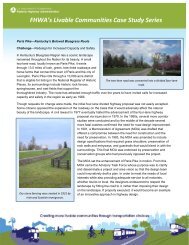
Rigid Linings<br />
Rigid linings (Figure 1) are useful in flow zones where high shear stress or<br />
non-uniform flow conditions exist, such as at transitions in channel shape or at an<br />
energy dissipation structure. In areas where loss <strong>of</strong> water or seepage from the<br />
channel is undesirable, they provide an impermeable lining. Since rigid linings are<br />
non-erodible the <strong>design</strong>er can use any channel shape that adequately conveys the<br />
flow and provides adequate freeboard. This may be necessary if right-<strong>of</strong>-way<br />
limitations restrict the channel size.<br />
Figure 1. Rigid Concrete Channel Lining<br />
Despite the non-erodible nature <strong>of</strong> rigid linings, they are highly susceptible to failure<br />
from structural instability. For example, cast-in-place or masonry linings <strong>of</strong>ten break<br />
up and deteriorate if foundation conditions are poor. Once a rigid linings<br />
deteriorates, it is very susceptible to erosion because the large, flat, broken slabs<br />
are easily moved by channel flow.<br />
The major causes <strong>of</strong> structural instability and failure <strong>of</strong> rigid linings are freeze-thaw,<br />
swelling, and excessive soil pore water pressures. Freeze thaw and swelling soils<br />
exert upward forces against the lining and the cyclic nature <strong>of</strong> these conditions can<br />
eventually cause failure. Excessive soil pore pressure occurs when the flow levels<br />
in the channel drop quickly. Side slope instability can develop from excessively high<br />
pore pressures and high hydraulic gradients along the slope surface.<br />
Construction <strong>of</strong> rigid linings requires specialized equipment and costly materials. As<br />
a result, the cost <strong>of</strong> rigid channel linings is high. Prefabricated linings can be a less<br />
expensive alternative if shipping distances are not excessive.
Flexible Linings<br />
Riprap and vegetation are suitable linings for hydraulic conditions similar to those<br />
requiring rigid linings. Because flexible linings are permeable, they may require<br />
protection <strong>of</strong> underlying soil to prevent washout. For example, filter cloth is <strong>of</strong>ten<br />
used with <strong>riprap</strong> to inhibit soil piping.<br />
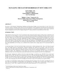
Vegetative and temporary linings are suited to hydraulic conditions where uniform<br />
flow exist and shear stresses are moderate. Vegetative channel linings are not<br />
suited to sustained flow conditions or long periods <strong>of</strong> submergence. Vegetative<br />
channels with sustained low flow and intermittent high flows are <strong>of</strong>ten <strong>design</strong>ed with<br />
a composite lining <strong>of</strong> a <strong>riprap</strong> or concrete low flow section, (Figure 2).<br />
Figure 2. Composite Channel Lining (<strong>riprap</strong> and jute net)<br />
Temporary linings provide erosion protection until vegetation is established. In most<br />
cases the lining will deteriorate over the period <strong>of</strong> one growing season, which<br />
means that successful re-vegetation is essential to the overall channel stabilization<br />
effort. Temporary channel linings may be used without vegetation to temporarily<br />
control erosion on construction sites.<br />
Information on Flexible Linings<br />
The following is a summary <strong>of</strong> materials currently available for use as flexible channel linings.<br />
Permanent Flexible Linings<br />
Vegetation: Vegetative linings consist <strong>of</strong> planted or sodden grasses placed in and<br />
along the drainage (Figure 3). If planted, grasses are seeded and fertilized<br />
according to the requirements <strong>of</strong> that particular variety or mixture. Sod is laid<br />
parallel to the flow direction and may be secured with pins or staples.<br />
Rock Riprap: Rock <strong>riprap</strong> is dumped in place on a filter blanket or prepared slope<br />
to form a well-graded mass with a minimum <strong>of</strong> voids (Figure 4). Rocks should be<br />
hard, durable, preferably angular in shape, and free from overburden, shale, and
organic material. Resistance to disintegration from channel erosion should be<br />
determined from service records or from specified field and laboratory tests.<br />
Figure 3. Vegetative Channel Lining (class D retardance)<br />
Figure 4. Riprap Channel Lining<br />
Wire-Enclosed Riprap: Wire-enclosed <strong>riprap</strong> is manufactured from a rectangular<br />
container made <strong>of</strong> steel wire woven in a uniform pattern, and reinforced on corners<br />
and edges with heavier wire (Figure 5). The containers are filled with stone,<br />
connected together, and anchored to the channel side slope. Stones must be well<br />
graded and durable. The forms <strong>of</strong> wire- enclosed <strong>riprap</strong> vary from thin mattresses to<br />
box-like gabions. Wire-enclosed <strong>riprap</strong> is typically used when rock <strong>riprap</strong> is either<br />
not available or not large enough to be stable.<br />
Gravel Riprap: Gravel <strong>riprap</strong> consists <strong>of</strong> coarse gravel or crushed rock placed on<br />
filter blankets prepared slope to form a well-graded mass with a minimum <strong>of</strong> voids<br />
(Figure 6). The material is composed <strong>of</strong> tough, durable, gravel-sized particles and<br />
should be free from organic matter.
Temporary Flexible Linings<br />
Figure 5. Wire-Enclosed Riprap<br />
Figure 6. Gravel Channel Lining<br />
Woven Paper Net: Woven paper net consists <strong>of</strong> knitted plastic netting, interwoven<br />
with paper strips (Figure 7 and Figure 8). The net is applied evenly on the channel<br />
slopes with the fabric running parallel to the flow direction <strong>of</strong> the channel. The net is<br />
secured with staples and by placement <strong>of</strong> fabric into cut<strong>of</strong>f trenches at intervals<br />
along the channel. Placement <strong>of</strong> woven paper net is usually done immediately after<br />
seeding operations.<br />
Figure 7. Woven Paper Net Channel Lining
Figure 8. Installed Woven Paper Net Lining<br />
Jute Net: Jute net consists <strong>of</strong> jute yarn, approximately 60 mm in diameter, woven<br />
into a net with openings that are about 10 by 20 mm. The jute net (Figure 9 and<br />
Figure 10) is loosely laid in the channel parallel to the direction <strong>of</strong> flow. The net is<br />
secured with staples and by placement <strong>of</strong> the fabric into cut<strong>of</strong>f trenches at intervals<br />
along the channel. Placement <strong>of</strong> jute net is usually done immediately after seeding<br />
operations.<br />
Figure 9. Jute Net Lining<br />
Figure 10. Installed Jute Net Channel Lining<br />
Fiberglass Roving: Fiberglass roving consists <strong>of</strong> continuous fibers drawn from<br />
molten glass, coated, and lightly bound together into roving. The roving is ejected<br />
by compressed air forming a random mat <strong>of</strong> continuous glass fibers. The material is<br />
spread uniformly over the channel and anchored with asphaltic materials (Figure 11<br />
and Figure 12).
Figure 11. Fiberglass Roving Lining<br />
Figure 12. Installation <strong>of</strong> Fiberglass Roving Along a Roadside<br />
Curled Wood Mat: Curled wood mat consists <strong>of</strong> curled wood with wood fibers, 80<br />
percent <strong>of</strong> which are 150 mm or longer, with a consistent thickness and an even<br />
distribution <strong>of</strong> fiber over the entire mat (Figure 13 and Figure 14). The top side <strong>of</strong><br />
the mat is covered with a biodegradable plastic mesh. The mat is placed in the<br />
channel parallel to the direction <strong>of</strong> the flow and secured with staples and cut<strong>of</strong>f<br />
trenches.<br />
Figure 13. Curled Wood Mat
Figure 14. Installed Curled Wood Mat Channel Lining<br />
Synthetic Mat: Synthetic mat consists <strong>of</strong> heavy synthetic mono-filaments which are<br />
fused at their intersections to form a blanket ranging in thickness from 6.0 to 20<br />
mm. The mat, shown in Figure 15 and Figure 16, is laid parallel to the direction flow.<br />
The mat is secured with staples or wooden stakes, and anchored into cut<strong>of</strong>f<br />
trenches at intervals along the channel. After the mat is in place the area is seeded<br />
through the openings in the mat and the cut<strong>of</strong>f trenches backfilled.<br />
Figure 15. Synthetic Mat Lining<br />
Figure 16. Installed Synthetic Mat Channel Lining<br />
Straw with Net: Straw with net consists <strong>of</strong> plastic material forming a net <strong>of</strong> 20 mm<br />
minimum square openings overlying straw mulch (Figure 17). Straw is spread<br />
uniformly over the area at a rate <strong>of</strong> approximately 4.5 metric tons/hectare and may<br />
be incorporated into the soil according to specifications. Plastic net is placed after
mulching with straw to secure the mulch to the finished channel.<br />
Go to Chapter 3<br />
Figure 17. Straw With Net Channel Lining
Go to Chapter 4<br />
Chapter 3 : HEC 15<br />
Design Concepts<br />
The <strong>design</strong> method presented in this circular is based on the concept <strong>of</strong> maximum permissible tractive<br />
force, coupled with the hydraulic resistance <strong>of</strong> the particular lining material. The method includes two<br />
parts, computation <strong>of</strong> the flow conditions for a given <strong>design</strong> discharge and determination <strong>of</strong> the degree<br />
<strong>of</strong> erosion protection required. The flow conditions are a function <strong>of</strong> the channel geometry, <strong>design</strong><br />
discharge, channel roughness, and channel slope. The erosion protection required can be determined<br />
by computing the shear stress on the channel at the <strong>design</strong> discharge and comparing the calculated<br />
shear stress to the permissible value for the type <strong>of</strong> channel lining used.<br />
Open-Channel Flow Concepts<br />
Type <strong>of</strong> Flow<br />
Open-channel flow can be classified according to three general conditions:<br />
1. uniform or non-uniform flow<br />
2. steady or unsteady flow<br />
3. subcritical or supercritical flow.<br />
In uniform flow, the depth and discharge remain constant along the channel. In steady flow,<br />
no change in discharge occurs over time. Most natural flows are unsteady and are<br />
described by run<strong>of</strong>f hydrographs. It can be assumed in most cases that the flow will vary<br />
gradually and can be described as steady, uniform flow for short periods <strong>of</strong> time. Subcritical<br />
flow is distinguished from super critical flow by a dimensionless number called the Froude<br />
number (Fr), which is defined as the ratio <strong>of</strong> inertial forces to gravitational forces in the<br />
system. Subcritical flow (Fr < 1.0) is characterized as tranquil and has deep, slower velocity<br />
flow. Supercritical flow (Fr > 1.0) is characterized as rapid and has shallow, high velocity<br />
flow.<br />
For <strong>design</strong> purposes, uniform flow conditions are usually assumed with the energy slope<br />
approximately equal to average bed slope. This allows the flow conditions to be defined by<br />
a uniform flow equation such as Manning's equation. Supercritical flow creates surface<br />
waves that are approaching the depth <strong>of</strong> flow. For very steep channel gradients, the flow<br />
may splash and surge in a violent manner and special considerations for freeboard are<br />
required.<br />
Resistance to Flow<br />
Depth <strong>of</strong> uniform flow in a channel depends on the roughness <strong>of</strong> a particular lining. For<br />
practical purposes in highway drainage engineering, Manning's equation provides a reliable<br />
estimate <strong>of</strong> uniform flow conditions. With a given depth <strong>of</strong> flow, d , the mean velocity may be
computed as:<br />
where:<br />
V = R 2/3 S f 1/2<br />
V = average velocity in the cross section<br />
n = Manning's roughness coefficient<br />
R = hydraulic radius, equal to the cross-sectional area, A, divided by the wetted perimeter,<br />
P<br />
S f = friction slope <strong>of</strong> the channel, approximated by the average bed slope for uniform flow<br />
The discharge in the channel is given by the continuity equation as:<br />
Q = AV<br />
(2)<br />
where:<br />
A = flow area in the channel.<br />
For most types <strong>of</strong> channel linings Manning's roughness coefficient, n, is approximately<br />
constant. The roughness coefficient will increase for very shallow flows where the height <strong>of</strong><br />
the roughness features on the lining approaches the flow depth (see Appendix A). For a<br />
<strong>riprap</strong> lining, the flow depth in small channels may be only a few times greater than the<br />
diameter <strong>of</strong> the mean <strong>riprap</strong> size. In this case, use <strong>of</strong> a constant n value is acceptable, but<br />
consideration <strong>of</strong> the shallow flow depth should be made by using a higher n value.<br />
A channel lined with a good stand <strong>of</strong> vegetation cannot be described by a single n value.<br />
The resistance to flow in vegetated channels is further complicated by the fact that<br />
vegetation will bend in the flow, changing the height <strong>of</strong> the vegetation. The Soil<br />
Conservation Service (SCS) (4) developed a classification <strong>of</strong> vegetation depending on the<br />
degree <strong>of</strong> retardance. Grasses are classified into five broad categories, as shown in Table 1<br />
in Chapter 4. Retardance Class A presents the highest resistance to flow and Class E<br />
presents the lowest resistance to flow. In general, taller and stiffer grass species have a<br />
higher resistance to flow, while short flexible grasses have a low-flow resistance.<br />
Recent studies by Kouwen et al.(5,6), examined the biomechanics <strong>of</strong> vegetation and<br />
provided a more general approach for determining the Manning's n value for vegetated<br />
channels. The resulting resistance equation (see Appendix B, equation 19) uses the same<br />
vegetative classification as the SCS but is more accurate for very stiff vegetation and mild<br />
channel gradients. Design Chart 5, Chart 6, Chart 7, Chart 8, and Chart 9 were developed<br />
from the Kouwen resistance equation.<br />
Channel Bends<br />
Flow around a bend in an open channel induces centrifugal forces because <strong>of</strong> the change in<br />
flow direction.(7) This results in a superelevation <strong>of</strong> the water surface. The water surface is<br />
higher at the outside <strong>of</strong> the bend than at the inside <strong>of</strong> the bend. This superelevation can be<br />
(1)
estimated by the equation:<br />
equation 3<br />
where:<br />
V = mean velocity<br />
T = surface width <strong>of</strong> the channel<br />
g = gravitational acceleration<br />
R c = mean radius <strong>of</strong> the bend.<br />
Flow around a channel bend imposes higher shear stress on the channel bottom and<br />
banks. The nature <strong>of</strong> the shear stress induced by a bend is discussed in more detail in the<br />
tractive force section. The increase stress requires additional <strong>design</strong> considerations within<br />
and downstream <strong>of</strong> the bend.<br />
Freeboard<br />
The freeboard <strong>of</strong> a channel is the vertical distance from the water surface to the top <strong>of</strong> the<br />
channel at <strong>design</strong> condition. The importance <strong>of</strong> this factor depends on the consequence <strong>of</strong><br />
overflow <strong>of</strong> the channel bank. At a minimum the freeboard should be sufficient to prevent<br />
waves or fluctuations in water surface from overflowing the sides. In a permanent roadway<br />
channel, about 0.15 m <strong>of</strong> freeboard should be adequate, and for temporary channels, no<br />
freeboard is necessary. Steep gradient channels should have a freeboard height equal to<br />
the flow depth. This allows for large variations to occur in flow depth for steep channels<br />
caused by waves, splashing and surging. Lining materials should extend to the freeboard<br />
elevation.<br />
Stable Channel Design Concepts<br />
Equilibrium Concepts<br />
Stable channel <strong>design</strong> concepts focus on evaluating and defining a channel configuration<br />
that will perform within acceptable limits <strong>of</strong> stability. Methods for evaluation and definition <strong>of</strong><br />
a stable configuration depend on whether the channel boundaries can be viewed as:<br />
1. essentially rigid (static)<br />
2. movable (dynamic).<br />
In the first case, stability is achieved when the material forming the channel boundary<br />
(3)
effectively resists the erosive forces <strong>of</strong> the flow. Under such conditions the channel bed and<br />
banks are in static equilibrium, remaining basically unchanged during all stages <strong>of</strong> flow.<br />
Principles <strong>of</strong> rigid boundary hydraulics can be applied to evaluate this type <strong>of</strong> system.<br />
In a dynamic system, some change in the channel bed and/or banks is to be expected if<br />
erosive forces <strong>of</strong> the flow are sufficient to detach and transport the materials comprising the<br />
channel boundary. Stability in a dynamic system is generally attained when the sediment<br />
supply rate equals the sediment transport rate. This condition, where sediment supply<br />
equals sediment transport, is <strong>of</strong>ten referred to as dynamic equilibrium. Although some<br />
detachment and transport <strong>of</strong> bed and/or bank materials may occur, this does not preclude<br />
attainment <strong>of</strong> a channel configuration that is basically stable. A dynamic system can be<br />
considered stable so long as the net change does not exceed acceptable levels. For most<br />
highway drainage channels, bank instability and possible lateral migration cannot be<br />
tolerated. Consequently, development <strong>of</strong> static equilibrium conditions or utilization <strong>of</strong> linings<br />
to achieve a stable condition is usually preferable to using dynamic equilibrium concepts.<br />
Two methods have been developed and are commonly applied to determine if a channel is<br />
stable in the sense that the boundaries are basically immobile (static equilibrium). These<br />
methods are defined as the permissible velocity approach and the permissible tractive force<br />
(shear stress) approach. Under the permissible velocity approach the channel is assumed<br />
stable if the adopted mean velocity is lower than the maximum permissible velocity. The<br />
tractive force (boundary shear stress) approach focuses on stresses developed at the<br />
interface between flowing water and materials forming the channel boundary. By Chow's<br />
definition, permissible tractive force is the maximum unit tractive force that will not cause<br />
serious erosion <strong>of</strong> channel bed material from a level channel bed.(7)<br />
Permissible velocity procedures were first developed around the 1920's. In the 1950's,<br />
permissible tractive force procedures became recognized, based on research investigations<br />
conducted by the U.S. Bureau <strong>of</strong> Reclamation. Procedures for <strong>design</strong> <strong>of</strong> vegetated channels<br />
using the permissible velocity approach were developed by the SCS and have remained in<br />
common use.<br />
In spite <strong>of</strong> the empirical nature <strong>of</strong> permissible velocity approaches, the methodology has<br />
been employed to <strong>design</strong> numerous stable channels in the United States and throughout<br />
the world. However, considering actual physical processes occurring in open-channel flow,<br />
a more realistic model <strong>of</strong> detachment and erosion processes is based on permissible<br />
tractive force .<br />
Tractive Force Theory<br />
The hydrodynamic force <strong>of</strong> water flowing in a channel is known as the tractive force . The<br />
basis for stable channel <strong>design</strong> with flexible lining materials is that flow-induced tractive<br />
force should not exceed the permissible or critical shear stress <strong>of</strong> the lining materials. In a<br />
uniform flow, the tractive force is equal to the effective component <strong>of</strong> the gravitational force<br />
acting on the body <strong>of</strong> water, parallel to the channel bottom.(7) The average tractive force on<br />
the channel, or shear stress is equal to:
τ = γRS<br />
(Where:<br />
γ=Unit Weight <strong>of</strong> Water<br />
R= Hydraulic Radius<br />
S= Average Bed Slope or Energy Slope<br />
The maximum shear stress, τ d , for a straight channel occurs on the channel bed (7, 8) and<br />
is less than or equal to the shear stress at maximum depth.<br />
τ d = γdS<br />
where:<br />
d = maximum depth <strong>of</strong> flow.<br />
Shear stress in channels is not uniformly distributed along the wetted perimeter. (9,10) A<br />
typical distribution <strong>of</strong> shear stress in a trapezoidal channel tends toward zero at the corners<br />
with a maximum on the center line <strong>of</strong> the bed, and the maximum for the side slopes<br />
occurring about the lower third <strong>of</strong> the side as shown in Figure 18. Flow around a bend<br />
creates secondary currents, which impose higher shear stresses the channel sides and<br />
bottom compared to a straight reach (11) as shown in Figure 19 . At the beginning <strong>of</strong> the<br />
bend, the maximum shear stress is near the inside and moves toward the outside as the<br />
flow leaves the bend. The increased shear stress caused by a bend persists downstream <strong>of</strong><br />
the bend, a distance, L P . The maximum shear stress in a bend is a function <strong>of</strong> the ratio <strong>of</strong><br />
channel curvature to bottom width, R C /B.(12). As R C /B decreases, that is as the bend<br />
becomes sharper, the maximum shear stress in the bend tends to increase ( see Chart 10 ).<br />
The bend shear stress, τ b, is expressed by a dimensionless factor, K b, multiplied by the<br />
shear stress in an equivalent straight section <strong>of</strong> channel where:<br />
τ b=K b τ d (6)<br />
The relationship between permissible shear stress and permissible velocity for a lining can<br />
be found by substituting equation 4 into equation 1 giving:<br />
Where:<br />
τ p = permissible shear stress.<br />
(4)<br />
(5)<br />
(7)
Figure 18. Typical Distribution <strong>of</strong> Shear Stress<br />
It can be seen from this equation that permissible velocity varies due to the hydraulic radius.<br />
However, permissible velocity is not extremely sensitive to hydraulic radius since the<br />
exponent is only 1/6. Equation 7 is useful in judging the field performance <strong>of</strong> a channel<br />
lining, because depth and velocity may be easier to measure in the field than water surface<br />
or channel gradient.<br />
The tractive force method is a more compact approach than the permissible velocity<br />
method, because the failure criteria for a particular lining is represented by a single critical<br />
shear stress value. This critical shear stress value is applicable over a wide range <strong>of</strong><br />
channel slopes and channel shapes. Permissible velocities, on the other hand, are a<br />
function <strong>of</strong> lining roughness, channel slope, and channel shape, and are only approximately<br />
constant over a range <strong>of</strong> these parameters. An accurate solution <strong>of</strong> the permissible velocity<br />
method therefore requires <strong>design</strong> nomographs The simpler representation <strong>of</strong> failure for the<br />
tractive force method is a definite advantage for users who prefer to use programmable<br />
calculators and microcomputers.<br />
Figure 19. Shear Stress Distribution in a Channel Bend (after 11)
Design Parameters<br />
Design Discharge Frequency<br />
Design flow rates for permanent roadside and median drainage channel linings usually have<br />
a 5 or 10 year return period. A lower return period flow is allowable if a temporary lining is to<br />
be used, typically the mean annual storm (approximately a 2-year return period, i.e., 50<br />
percent probability <strong>of</strong> occurrence in a year). Temporary channel linings are <strong>of</strong>ten used<br />
during the establishment <strong>of</strong> vegetation. The probability <strong>of</strong> damage during this relatively short<br />
time is low, and if the lining is damaged, repairs are easily made. Design procedures for<br />
determining the maximum permissible discharge in a roadway channel are given in Chapter<br />
4.<br />
Channel Cross Section Geometry<br />
Most highway drainage channels are trapezoidal or triangular in shape with rounded<br />
corners. For <strong>design</strong> purposes, a trapezoidal or triangular representation is sufficient. Design<br />
<strong>of</strong> roadside channels should be integrated with the highway geometric and pavement<br />
<strong>design</strong> to insure proper consideration <strong>of</strong> safety and pavement drainage needs. If available<br />
channel linings are found to be inadequate for the selected channel geometry, it may be<br />
feasible to widen the channel. This can be accomplished by either increasing the bottom<br />
width or flattening the side slopes. Widening the channel will reduce the flow depth and<br />
lower the shear stress on the channel perimeter.<br />
It has been demonstrated that if a <strong>riprap</strong>-lined channel has 1V:3H or flatter side slopes,<br />
there is no need to check the banks for erosion. (8) With steeper side slopes, a combination<br />
<strong>of</strong> shear stress against the bank and the weight <strong>of</strong> the lining may cause erosion on the<br />
banks before the channel bottom is disturbed. The <strong>design</strong> method in this manual includes<br />
procedures for checking the adequacy <strong>of</strong> channels with steep side slopes.<br />
Equations for determining cross-sectional area, wetted perimeter, and top width <strong>of</strong> channel<br />
geometries commonly used for highway drainage channels are given in Appendix A.<br />
Channel Slope<br />
The channel bottom slope is generally dictated by the roadway pr<strong>of</strong>ile and therefore is<br />
usually fixed. If channel stability conditions warrant and available linings are not sufficient, it<br />
may be feasible to reduce the channel gradient slightly relative to the roadway pr<strong>of</strong>ile. For<br />
channels outside the roadway right-<strong>of</strong>-way, The slope may be adjusted slightly.<br />
Channel slope is one <strong>of</strong> the major parameters in determining shear stress. For a given<br />
<strong>design</strong> discharge, the shear stress in the channel with a mild or subcritical slope is smaller<br />
than a channel with supercritical slope. Roadside channels with gradients in excess <strong>of</strong><br />
about two percent will flow in a supercritical state. Most flexible lining materials are suitable<br />
for protecting channel gradients <strong>of</strong> up to 10 percent. Riprap and wire-enclosed <strong>riprap</strong> are<br />
more suitable for protecting very steep channels with gradients in excess <strong>of</strong> 10 percent.
Go to Chapter 4
Go to Chapter 5<br />
Chapter 4 : HEC 15<br />
Design Procedure<br />
Design Procedure<br />
This section outlines the <strong>design</strong> procedure for flexible channel linings. Channels with steep gradients (slopes greater than 10%)<br />
will usually produce a tractive force in excess <strong>of</strong> the permissible shear stress for most linings presented in this chapter at<br />
relatively small discharges. Also, when <strong>riprap</strong> is used on steeper gradients, the <strong>design</strong> procedure must take into consideration the<br />
additional forces acting on the <strong>riprap</strong>. Designs involving <strong>riprap</strong> should be checked and compared to results obtained from <strong>design</strong><br />
procedures presented in Chapter 5. Steep Gradient Design. The more conservative results, i.e., largest <strong>riprap</strong> size, should be<br />
used for <strong>design</strong>. Other linings presented in this chapter are applicable over a wide range <strong>of</strong> channel gradients, provided the<br />
permissible shear for the lining is not exceeded.<br />
The basic <strong>design</strong> procedure is supplemented for <strong>riprap</strong> lined channels with side slopes steeper than 1V:3H. Use <strong>of</strong> side slopes<br />
steeper than 1V:3H is not encouraged for flexible linings other than <strong>riprap</strong> or gabions because <strong>of</strong> the potential for erosion <strong>of</strong> the<br />
side slopes. If a combination <strong>of</strong> linings is used, the composite channel lining procedure outlined in Chapter 6 should be used. In<br />
cases where flexible linings discussed in this circular do not provide adequate protection, other alternatives, including rigid linings<br />
should be considered. Because <strong>of</strong> the substantial increased cost <strong>of</strong> rigid linings, and their vulnerability to failure, other<br />
alternatives such as use <strong>of</strong> additional inlets, a modified channel geometry or a flatter channel gradient are preferred.<br />
Flexible Lining Design<br />
The basic <strong>design</strong> procedure for flexible channel linings is quite simple. It involves only two computations and several<br />
straight forward comparisons <strong>of</strong> lining performance. The computations include a determination <strong>of</strong> the uniform flow<br />
depth in the channel, known as the normal depth, and determination <strong>of</strong> the shear stress at maximum flow depth.<br />
Designers familiar with methods for determining normal depth may use any convenient method and the Manning's<br />
roughness coefficients provided in this manual. A nomograph is also provided in this chapter for determining the<br />
normal depth in trapezoidal channels. The computation for shear stress is much simpler and can be carried out<br />
without the need <strong>of</strong> any <strong>design</strong> aids.<br />
The basic comparison required in the <strong>design</strong> procedure is that <strong>of</strong> permissible to computed shear stress for a lining. A<br />
table and two figures are provided that give permissible shear stress values for a variety <strong>of</strong> lining types. If the
permissible shear stress is greater than the computed shear, the lining is considered acceptable. If a lining is<br />
unacceptable, a lining with a higher permissible shear stress is selected and the calculations for normal depth and<br />
shear stress is repeated. A worksheet is provided at the end <strong>of</strong> this chapter (Figure 23) for carrying out the <strong>design</strong><br />
procedures presented in this chapter.<br />
Channels lined with gravel or <strong>riprap</strong> on side slopes steeper than 1V:3H must be <strong>design</strong>ed using the steep side slope<br />
<strong>design</strong> procedure. Steep side slopes are allowable within a channel if cohesive soil conditions exist. Channels with<br />
steep slopes should not be allowed if the channel is constructed in non-cohesive soils.<br />
Permissible Shear Stress<br />
The permissible shear stress, τ p , indicates the force required to initiate movement <strong>of</strong> the lining material. Prior to<br />
movement <strong>of</strong> the lining, the underlying soil is relatively protected. Therefore permissible shear stress is not<br />
significantly affected by the erodibility <strong>of</strong> the underlying soil. However, if the lining is eroded and moved, the bed<br />
material is exposed to the erosive force <strong>of</strong> the flow. The consequence <strong>of</strong> lining failure on highly erodible soils is great,<br />
since the erosion rate after failure is high compared to soils <strong>of</strong> low erodibility.<br />
Values for permissible shear stress for linings are based on research conducted at laboratory facilities and in the<br />
field. The values presented here are judged to be conservative and appropriate for <strong>design</strong> use. Table 2 presents<br />
permissible shear stress values for manufactured, vegetative, and <strong>riprap</strong> lining types. The permissible shear stress for<br />
non-cohesive soils is a function <strong>of</strong> mean diameter <strong>of</strong> the channel material as shown in Chart 1. For larger stone sizes<br />
not shown in Chart 1 and rock <strong>riprap</strong>, the permissible shear tress is given by the following equation:<br />
p =628.3 D (8)<br />
50<br />
where:<br />
D 50 is the mean <strong>riprap</strong> size in meters<br />
For cohesive materials the variation in permissible shear stress is governed by many soil properties. The plasticity<br />
index <strong>of</strong> the cohesive soil provides a good guide to the permissible shear stress as shown in Chart 2.
Determination <strong>of</strong> Normal Flow Depth<br />
The condition <strong>of</strong> uniform flow in a channel at a known discharge is computed using the Manning's equation combined<br />
with the continuity equation:<br />
Where:<br />
Q = discharge<br />
n = Manning's roughness coefficient<br />
A = cross-sectional area<br />
R = hydraulic radius<br />
S f = friction gradient which, for uniform flow conditions, equals the<br />
channel bed gradient, S.<br />
Chart 3 provides a solution to Manning's equation for trapezoidal channels. The geometric properties <strong>of</strong> a trapezoidal<br />
channel can be found using Chart 4 or the equations provided in Appendix A.<br />
Manning's Roughness Coefficients for Non-Vegetative Linings<br />
Table 3 gives recommended values <strong>of</strong> the Manning's roughness coefficient for flexible channel lining materials,<br />
including <strong>riprap</strong>-type lining materials. The n values will vary with flow depth. The channel roughness will be higher for<br />
shallow flow depths and lower for large flow depths. The range <strong>of</strong> flow depths from 150 mm to 600 mm is typical <strong>of</strong><br />
highway drainage channels should be used in most cases.<br />
Manning's Roughness Coefficients for Vegetative Linings<br />
Manning's roughness coefficient for vegetative linings varies significantly depending on the amount <strong>of</strong> submergence<br />
<strong>of</strong> the vegetation and the flow force exerted on the channel bed. As a result, the Manning's n value must be<br />
determined by trial and error taking into consideration both the depth <strong>of</strong> flow and the flow force. Chart 5, Chart 6,<br />
Chart 7, Chart 8, and Chart 9 show the variation in Manning's n for five classes <strong>of</strong> vegetation. These charts can be<br />
used to determine Manning's n for a wide range <strong>of</strong> flow conditions.<br />
(9)
Determination <strong>of</strong> Shear Stress on Channel<br />
As presented in Chapter 3, Tractive Force Theory, the shear stress on the channel lining at maximum depth, τ d, is<br />
computed using the following equation:<br />
Equation 5 from Chapter 3<br />
τ d = γds<br />
where:<br />
γ = unit weight <strong>of</strong> water (9810 N/m 3 )<br />
d = flow depth m<br />
S = channel gradient, m/m<br />
Flow around a channel bend imposes higher shear stress on the channel bottom and banks. For bends, the<br />
maximum shear stress is given by the following equation:<br />
Equation 6 from Chapter 3<br />
τ b =K b τ d<br />
where:<br />
the value <strong>of</strong> K b can be found using Chart 10.<br />
In Chart 10, the radius <strong>of</strong> curvature <strong>of</strong> the channel center line, R C, and the bottom width <strong>of</strong> the channel, B. determine<br />
the magnitude <strong>of</strong> factor K b . The length <strong>of</strong> protection, L p , required downstream <strong>of</strong> a bend is found using Chart 11. The<br />
length <strong>of</strong> protection is a function <strong>of</strong> the roughness <strong>of</strong> the lining material in the bend (n b ) and the depth <strong>of</strong> flow.<br />
Side Slope Stability<br />
Channels lined with gravel or <strong>riprap</strong> on side slopes steeper than 1V:3H may become unstable. As the angle <strong>of</strong> the<br />
side slopes approaches the angle <strong>of</strong> repose <strong>of</strong> the channel lining, the lining material becomes less stable. However,<br />
the shear stress on the channel side is less than the maximum shear stress occurring on the channel bed. The<br />
stability <strong>of</strong> a side slope is a function <strong>of</strong> the channel side slope and the angle <strong>of</strong> repose <strong>of</strong> the rock lining material.<br />
When the tractive force ratio is compared to the ratio <strong>of</strong> the shear stress on the sides to the shear stress on the
ottom <strong>of</strong> the channel, the rock size for the channel side slope can be determined. The angle <strong>of</strong> repose, θ. for<br />
different rock shapes and sizes is provided in Chart 12. The ratio <strong>of</strong> shear stress on the sides and bottom <strong>of</strong> a<br />
trapezoidal channel, K 1, is given in Chart 13 and the tractive force ratio, K 2, is given in Chart 14. The required rock<br />
size (mean diameter <strong>of</strong> the gradation D 50) for the side slopes is found using the following equation:<br />
equation 10<br />
Maximum Discharge Approach<br />
In many cases, the <strong>design</strong>er simply needs to know the maximum discharge a channel can convey given the<br />
permissible shear stress and the corresponding allowable depth. By knowing the maximum discharge that a lining<br />
can sustain, the <strong>design</strong>er can determine the maximum length <strong>of</strong> lining for a channel, based on the hydrology <strong>of</strong> the<br />
site. This information can assist the <strong>design</strong>er in an economic evaluation <strong>of</strong> lining types and can determine inlet<br />
spacing.<br />
The procedure presented is for both vegetative linings and non-vegetative linings. Applying the procedure for<br />
vegetative linings is particularly useful, since it does not involve a trial and error solution.<br />
Design Considerations for Riprap Lining<br />
Two additional <strong>design</strong> considerations are required for <strong>riprap</strong> channel linings:<br />
1. Riprap gradation and thickness<br />
Use <strong>of</strong> filter material under rock <strong>riprap</strong> .<br />
2.<br />
Riprap Gradation and Thickness<br />
Riprap gradation should follow a smooth size distribution curve. Most <strong>riprap</strong> gradations will fall in the<br />
range <strong>of</strong> D 100 /D 50 and D 50 /D 20 between 3.0 to 1.5, which is acceptable. The most important criterion is a<br />
proper distribution <strong>of</strong> sizes in the gradation so that interstices formed by larger stones are filled with<br />
(10)
smaller sizes in an interlocking fashion, preventing the formation <strong>of</strong> open pockets. These gradation<br />
requirements apply regardless <strong>of</strong> the type <strong>of</strong> filter <strong>design</strong> used.<br />
In general, <strong>riprap</strong> constructed with angular stones has the best performance. Round stones are<br />
acceptable as <strong>riprap</strong> provided they are not placed on side slopes steeper than 1V:3H. Flat slab-like stones<br />
should be avoided since they are easily dislodged by the flow. An approximate guide to stone shape is<br />
that neither the breadth nor thickness <strong>of</strong> a single stone is less than one-third its length.<br />
The thickness <strong>of</strong> a <strong>riprap</strong> lining should equal the diameter <strong>of</strong> the largest rock size in the gradation. For<br />
most gradations, this will mean a thickness from 1.5 to 3.0 times the mean <strong>riprap</strong> diameter.<br />
Filter Design<br />
When rock <strong>riprap</strong> is used, the need for an underlying filter material must be evaluated. The filter material<br />
may be either a granular filter blanket or a engineering fabric.<br />
For a granular filter blanket , the following criteria must be met:<br />
In the above relationships, "filter" refers to the overlying material and "base" refers to the underlying<br />
material. The relationships must hold between the filter blanket and base material and between the <strong>riprap</strong><br />
and filter blanket .<br />
(11)<br />
(12)
The thickness <strong>of</strong> the granular filter blanket should approximate the maximum size in the filter gradation.<br />
The minimum thickness for a filter blanket should not be less than 150 mm.<br />
In selecting an engineering filter fabric, the fabric should be able to transmit water from the soil and also<br />
have a pore structure that will hold back soil. The following properties <strong>of</strong> an engineering filter fabric are<br />
required to assure that their performance is adequate as a filter under <strong>riprap</strong>. (18)<br />
1. The fabric must be able to transmit water faster than the soil.<br />
2. The following criteria for the apparent opening size (AOS) must be met:<br />
. For soil with less than 50 percent <strong>of</strong> the particles by weight passing a U.S. No. 200<br />
sieve, AOS < 0.6 mm (greater than #30 U.S. Std. Sieve).<br />
b. For soil with more than 50 percent <strong>of</strong> the particles by weight passing a U.S. No. 200<br />
sieve, AOS < 0.297 mm (greater that #50 U.S. Std. Sieve).<br />
The above criteria only applies to non-severe or non-critical installations. Severe or critical installations<br />
should be <strong>design</strong>ed based on permeability tests.<br />
Design Procedure<br />
The <strong>design</strong> procedure is summarized below. The procedure for flexible linings is a basic stepwise solution approach.<br />
Flexible Lining Design Procedure<br />
(see computation sheet, Figure 23)<br />
Step 1 . Select a flexible lining and determine the permissible shear stress, τ p (see Table 2)<br />
Step 2. Estimate flow depth for vegetation or flow depth range for linings, the channel shape, slope and <strong>design</strong><br />
discharge(s) .<br />
Step 3 . Determine Manning's n value for estimated flow depth.<br />
. For non-vegetative linings, use Table 3<br />
b.<br />
For vegetation:
1.<br />
2.<br />
Calculate the hydraulic radius, R. (Use Chart 4 for trapezoidal channels and Appendix A for other<br />
shapes.)<br />
Determine n from Chart 5, Chart 6, Chart 7, Chart 8, or Chart 9.<br />
Step 4. Calculate the flow depth, d, in the channel. (Chart 3 for trapezoidal channels.)<br />
Step 5 . Compare computed flow depth, d, with estimated flow depth, d i. If d is outside the assumed range for<br />
non-vegetative linings or differs by more than 0.030 m from d i for vegetation, repeat steps 2 through 4.<br />
Step 6. Calculate the shear stress, τ d. If τ d > τ p, the lining is not acceptable, repeat steps 1 through 5.<br />
τ d = γdS .<br />
Step 7. For channel bends:<br />
.<br />
b.<br />
c.<br />
4.<br />
Determine the factor for maximum shear stress on channel bends, K b, from Chart 10. This is a function <strong>of</strong> the<br />
ratio <strong>of</strong> channel curvature to bottom width, Rc/B.<br />
Calculate the shear stress in the bend, τ b.<br />
τ b =K b τ d<br />
If τ b > τ p, the lining is not acceptable, repeat steps 1 through 7.<br />
Calculate length <strong>of</strong> protection, L p , downstream <strong>of</strong> the bend from Chart 11.<br />
Calculate superelevation.<br />
Step 8. For <strong>riprap</strong> or gravel linings on steep side slopes (steeper than 1V:3H):<br />
.<br />
b.<br />
c.<br />
Determine the angle <strong>of</strong> repose for the rock size and shape from Chart 12.<br />
Determine K 1, the ratio <strong>of</strong> maximum side shear to maximum bottom shear for a trapezoidal channel from Chart<br />
13.<br />
Determine K 1, the tractive force ratio from Chart 14.<br />
4.<br />
Calculate the required D50 for the side slopes.<br />
(6)<br />
(3)
Step 9. For <strong>riprap</strong> on slopes greater than 10% check <strong>design</strong> procedure in Chapter 5. Use whichever procedure<br />
results in the larger <strong>riprap</strong> size.<br />
Maximum Discharge Design Procedure<br />
Step 1. Determine the allowable depth <strong>of</strong> flow in the channel using the permissible shear stress (Table 2 or Chart 1 or Chart<br />
2). Check that this depth does not exceed the depth (including freeboard) provided in the typical roadway section.<br />
Step 2. Determine the area and hydraulic radius corresponding to the allowable depth using Chart 4.<br />
Step 3. For non-vegetative linings, find the correct Manning's n from Table 3.<br />
For vegetative linings, enter into Chart 5, Chart 6, Chart 7, Chart 8, and Chart 9 for the correct vegetation class and determine<br />
the Manning's n value.<br />
Step 4. Solve Manning's equation(equation 9) to determine the maximum discharge for the channel.<br />
Example Problems<br />
(13)<br />
(10)
Example #1<br />
Determine whether it is feasible to use jute net as a temporary lining .<br />
Given: Q = 0.566 m 3/s<br />
S = 0.005 m/m<br />
Trapezoidal channel with a bottom width <strong>of</strong> 1.22 m and 1V:3H side slopes.<br />
Find: Depth <strong>of</strong> flow in the channel and the adequacy <strong>of</strong> the jute net lining<br />
Solution:<br />
1. From Table 2, the permissible shear stress is 21.5 N/m 2 and from Table 3, the Manning's n value is 0.022<br />
(assuming a flow depth between 0.15 to 0.60 m).<br />
2. Entering Chart 3 for S=0.005<br />
Qn=0.012<br />
B=1.22<br />
d/B=0.22<br />
d=0.268 m<br />
The flow depth has remained within the range <strong>of</strong> 0.15 to 0.60 m so that the assumed Manning's n value is<br />
correct.<br />
3. Using equation 5, the shear stress on the channel bed at maximum depth is,<br />
τ d = γds = 9810 x 0.268 x 0.005 = 13.1 N/m 2<br />
4. Comparing the shear stress, 13.1 N/m 2, to the permissible shear stress, 21.5 N/m 2 shows that jute net is an<br />
acceptable channel lining.<br />
Example #2<br />
Determine if a single application <strong>of</strong> fiberglass roving lining is an adequate lining for a median ditch.<br />
Given: B = 0.61 m<br />
Z = 4<br />
S = 0.05 m/m<br />
Q = 0.283 m 3/s
Find: Depth <strong>of</strong> flow .<br />
Solution:<br />
1. From Table 3, Manning's n is 0.021 assuming a flow depth in the range <strong>of</strong> 0.15 to 0.60 m<br />
2. Entering Chart 3 for S = 0.05, given<br />
Qn = 0.0059 m 3 /s<br />
B = 0.61<br />
d/B = 0.21<br />
d = 0.128 m<br />
Checking the flow depth against the initial assumed range shows that the computed depth is below that range. The<br />
Manning's n for flow depth range <strong>of</strong> 0.0 to 0.15 m is 0.028.<br />
Enter Chart 3 for S=0.05<br />
Qn = 0.007 m 3 /s<br />
B = 0.61<br />
d/B = 0.24<br />
d = 0.146 m<br />
The computed flow depth is within the assumed range.<br />
3.The maximum shear stress from equation 5 is,<br />
τ d = γds = 9810 x 0.146 x 0.05<br />
= 71.6 N/m 2<br />
4. The permissible shear stress for fiberglass is 28.7 N/m 2 . Since this is less than the maximum shear stress, the<br />
lining is not adequate.<br />
Example #3<br />
A roadside ditch is lined with a good stand <strong>of</strong> uncut buffalo grass. Determine the flow depth and Manning's n for the<br />
depth at <strong>design</strong> discharge.<br />
Given: Q = 0.566m 3 /s<br />
S = 0.005 m/m
Find:<br />
B = 1.22 m<br />
z = 4<br />
1. Manning's n value.<br />
2. Flow depth in the channel.<br />
Solution:<br />
The vegetative retardance classification is found in Table 1. A good stand <strong>of</strong> uncut buffalo grass is classified as<br />
retardance D. The determination <strong>of</strong> Manning's n and flow depth for a vegetative lining may require several trials.<br />
Trial 1<br />
1. Initial depth is estimated at 0.3 m<br />
2. From Chart 4 for Z = 4 and d/B = 0.25 m<br />
R/d = 0.65<br />
R = 0.195 m<br />
3. Entering Chart 8 given R = 0.2 m and S = 0.005 m<br />
n = 0.088<br />
4. Entering Chart 3 given S = 0.005, Qn = 0.0498 m 3 /s, B = 1.22 m, and Z = 4 m<br />
d/B = 0.40<br />
d = 0.488 m<br />
5. Since the difference between the initial and calculated depth is greater than 0.03 m, the procedure<br />
is repeated.<br />
Trial 2
1.Use the calculated depth <strong>of</strong> 0.488 m from trial 1.<br />
2. From Chart 4 for Z = 4 and d/B = 0.40<br />
R/d = 0.61<br />
R = 0.298 m<br />
3. Entering Chart 8 given R = 0.298 m and S = 0.005 m,<br />
n = 0.066<br />
4. Entering Chart 3 given S = 0.005<br />
Qn = 0.0374<br />
B =1.22 m<br />
d/B = 0.36<br />
d = 0.439 m<br />
5. Since the difference between the initial and calculated depths is 0.049 m which is greater than 0.03<br />
m the procedure is repeated.<br />
Trial 3<br />
1. Use the calculated depth <strong>of</strong> 0.439 m from trial 2.<br />
2. From Chart 4 for Z = 4 and d/B = 0.36<br />
R/d = 0.61<br />
R = 0.268 m<br />
3. Entering Chart 8 given R = 0.268 m and S = 0.005 m,<br />
n = 0.070<br />
4. Entering Chart 3 given S = 0.004, Qn =0.0396 m 3/s, and B =1.22,<br />
d/B = 0.37<br />
d = 0.45 m
5. The initial depth and the calculated depth are in agreement. The procedure is completed with the<br />
following results:<br />
Example #4<br />
n=0.070<br />
d=0.45 m<br />
Determine a temporary channel lining for a trapezoidal channel.<br />
Given: Q = 0.45 m 3/s<br />
S = 0.03 m/m<br />
B = 1.22 m<br />
Z = 3<br />
Find: Adequate temporary channel lining.<br />
Solution:<br />
Trial 1<br />
Jute net is selected as an initial channel lining alternative. The permissible shear stress (Table 2) and<br />
Manning's n value (Table 3) are,<br />
τ p = 21.5 N/m 2<br />
n = 0.022 (assuming a depth range <strong>of</strong> 0.15 to 0.60 m<br />
2. The flow depth is determined from Chart 3. Given S=0.03, Qn = 0.010, and B = 1.22 m<br />
d/B = 0.12<br />
d = 0.146 m<br />
The flow depth is slightly below the specified range for Manning's n.<br />
3. The shear stress at maximum depth is found using equation 5,<br />
τ d = 9810 x 0.146 x 0.03 = 43.0 N/m 2
4. The computed shear stress <strong>of</strong> 43.0 N/m 2 is greater than the permissible shear stress <strong>of</strong> 21.5 N/m 2<br />
so jute net would not be an acceptable lining.<br />
Trial 2<br />
1. The next lining chosen is curled wood mat because the permissible shear stress for this lining<br />
exceeds the calculated shear stress from the first trial. Fiberglass roving was not chosen since its<br />
permissible shear stress was less than the calculated shear stress from the first trial. The permissible<br />
shear from Table 2 and the Manning's n from Table 3 for curled wood mat are,<br />
τ p = 74.2 N/m 2<br />
n = 0.035 (assuming a depth range <strong>of</strong> 0.15 to 0.60 m)<br />
2. The flow depth is determined from Chart 3. given S=0.030, Qn = 0.0158, B = 1.22 m, and Z=3,<br />
d/B = 0.15<br />
d = 0.183 m<br />
The flow depth is within the specified range for Manning's n value used.<br />
3. The shear stress at maximum depth is found using equation 5,<br />
τ d = 9810 x 0.183 x 0.03 = 53.8 N/m 2<br />
4. The computed shear stress <strong>of</strong> 53.8 N/m 2 is less than the permissible shear stress <strong>of</strong> 74.2 N/m 2 so<br />
curled wood mat is an acceptable lining.<br />
Example #5<br />
Use <strong>of</strong> worksheets for this problem is illustrated in Figure 21.<br />
Determine an acceptable channel lining for the roadside channel in example 4 if a bend is included in the channel<br />
alignment.<br />
Given: 45 o channel bend<br />
R C = 6.1 m
Find:<br />
1. The channel lining required for the bend and the location <strong>of</strong> the lining.<br />
2. The superelevation <strong>of</strong> the water surface in the bend.<br />
Solution :<br />
Trial 1<br />
1. From the results <strong>of</strong> example 4, the shear stress <strong>of</strong> the straight reach upstream <strong>of</strong> the bend is,<br />
τ d = 53.8 N/m 2<br />
A curled wood mat lining was used to stabilize the channel.<br />
2. The shear stress in the bend is given by equation 6. The value <strong>of</strong> K b in equation 6 is found from<br />
Chart 10 given R C/B = 5,<br />
K b = 1.6<br />
The bend shear stress is,<br />
τ b = 1.6 x 53.8 = 86.1 N/m 2<br />
3. The computed shear stress in the bend is greater than the permissible shear stress for a curled<br />
wood mat channel lining (74.2 N/m 2). A new lining is required for the channel bend.<br />
Trial 2<br />
1. Synthetic mat is chosen as a bend lining material, because its permissible shear stress from Table 2<br />
(95.8 N/m 2 ) is greater than the computed shear stress from trial 1. The Manning's n value is 0.025 for a<br />
flow depth range from 0.15 to 0.60 m.<br />
2. Entering Chart 3 given S = 0.03, Qn = 0.011, and B = 1.22 m
d/B = 0.13<br />
d = 0.159 m<br />
This depth falls within the range originally assumed for Manning's n.<br />
3. The shear stress from equation 5,<br />
τ d = 9810 x 0.159 x 0.03 = 46.8 N/m 2<br />
The bend shear stress from equation 6 is,<br />
τ b = 1.6 x 46.8 = 74.9 N/m 2<br />
4. The calculated bend shear stress is less than the permissible shear stress for synthetic mat <strong>of</strong> 95.8<br />
N/m 2. Synthetic mat therefore provides an acceptable channel bend lining.<br />
5. The synthetic mat will extend through the bend and a distance downstream. The downstream<br />
distance is found using Chart 11, given n b = 0.025, R = 0.12 m (from Chart 4 for d/B = 0.13 and Z = 3),<br />
L p /R = 15.9<br />
L p = 1.91 m<br />
The total length <strong>of</strong> synthetic mat lining is the sum <strong>of</strong> the length in the bend plus the length required for<br />
downstream protection. The following figure shows the required location <strong>of</strong> lining materials.<br />
Figure 20. Location Sketch <strong>of</strong> Flexible Linings for Example 5
6. The superelevation <strong>of</strong> the water surface is computed from equation 3. To execute equation 3, top<br />
width and cross-sectional area must be computed, where,<br />
and<br />
T = B + 2Zd = 1.22 + 2 x 3 x 0.158 = 2.16 m<br />
A = Bd + Zd 2 = 1.22 x 0.158 + 3 x 0.158 2 = 0.268 m 2<br />
The velocity in the channel found using the continuity equation<br />
(equation 2),<br />
V = Q/A = 0.45/0.268 = 1.68 m/s<br />
Solving equation 3 given V = 1.68 m/s, T = 2.16 m, and R c=6.1m<br />
The freeboard in the channel bend should be at least 0.10 meters to accommodate the super elevation <strong>of</strong><br />
the water surface.<br />
Use <strong>of</strong> the worksheets for this problem is illustrated in Figure 21.<br />
Example #6<br />
Because <strong>of</strong> a width constraint on available right-<strong>of</strong>-way, the side slopes <strong>of</strong> a roadside ditch must be steepened to<br />
1V:2H. The 51-mm gravel lining has been determined to be adequate to protect the ditch bed. Determine the gravel<br />
size, D 50, necessary to protect the ditch banks.<br />
Given: Very rounded gravel<br />
A trapezoidal channel.<br />
Z = 2
B = 1.07 m<br />
Flow depth, d = 0.213 m<br />
Find: D 50 for side slopes.<br />
Solution:<br />
1. From Chart 12 given a D 50= 0.051 m the angle <strong>of</strong> repose θ = 36 o<br />
2. From Chart 13 given B/d = 5.0 the ratio <strong>of</strong> side shear to bottom shear, K 1= 0.79<br />
3. From Chart 14 given Z=2 and θ=36 o, the tractive force ratio, K 2 =0.65<br />
4. The required side slope D 50 from equation 10 is,<br />
Example #7<br />
Determine the maximum allowable discharge for a median ditch lined with a good stand <strong>of</strong> Kentucky bluegrass<br />
(approximately 200 mm in height). The ditch has a depth <strong>of</strong> 0.914 meters from the roadway shoulder.<br />
Given: S=0.010 m/m<br />
B=1.22 m<br />
Z=4<br />
Find: Maximum allowable discharge.<br />
Solution:<br />
1. From Table 1, a good stand <strong>of</strong> Kentucky bluegrass is classified as retardance C. From Table 2 the permissible<br />
shear stress,<br />
τp = 47.9 N/m2 Determine the allowable depth from equation 5, given τ d =τ p .
d = τ p /γS = 47.9 = 0.488 m<br />
9810 x 0.01<br />
Note: The allowable depth is less than the depth <strong>of</strong> the ditch.<br />
2. Determine the flow area and hydraulic radius from Chart 4, given d/B = 0.40,<br />
A/Bd = 2.6<br />
A = 1.55 m 2<br />
R/d = 0.61<br />
R = 0.3 m<br />
3. From Chart 7: n=0.072.<br />
4. Solving the Manning's equation with continuity equation (equation 9),<br />
Q= 1 AR 2/3 S 1/2 = 1 x 1.55 x 0.3 2/3 x 0.01 1/2 = 0.96 m 3 /s<br />
n 0.072
Example #8<br />
Determine the need for a granular filter blanket.<br />
Given: Riprap Gradation<br />
D 85 =0.40 m<br />
D 50 =0.20 m<br />
D 15 =0.10 m<br />
Base Soil Gradation<br />
D 85 =1.5 mm=0.0049 ft<br />
D 50 = 0.5 mm=0.0016 ft<br />
D 15 =0.167mm=0.00055 ft<br />
Figure 21. Worksheet for Example Problems 4 and 5
Find: Granular Filter Blanket Requirement.<br />
Solution:<br />
Since the relationship between <strong>riprap</strong> and base do not meet the recommended dimensional criteria, a filter blanket is<br />
required. First, determine the required dimensions <strong>of</strong> the filter with respect to the base material.<br />
D 50 filter < 40, so D50 filter < 40 x 0.5 mm = 20 mm<br />
D 50 base<br />
D 15 filter < 40, so D15 filter < 40 x 0.167 mm = 6.7 mm<br />
D 15 base<br />
D 15 filter < 5, so D15 filter < 5 x 1.5 mm = 7.3 mm<br />
D 85 base<br />
D 15 filter > 5, so D15 filter > 5 x 0.167 mm = 0.84 mm<br />
D 15 base<br />
Therefore, with respect to the base material, the filter must satisfy:<br />
D 50 filter < 20 m<br />
0.84 m 0.20 = 5.0 m<br />
D 50 filter 40<br />
D 15 <strong>riprap</strong> < 40, So , D 15 filter > 0.10 = 2.5 mm<br />
D 15 filter 40<br />
D 15 <strong>riprap</strong> 0.10
D85 filter < 5, So , D85 filter > 5 = 20 mm<br />
D 15 <strong>riprap</strong><br />
> 5, So , D15 filter > 0.10 = 20 mm<br />
D15 filter 5<br />
With respect to the <strong>riprap</strong>:<br />
D 50 filter > 5.0 mm<br />
2.5 mm < D 15 filter < 20.0 mm<br />
D 85 filter > 20.0 mm<br />
Combining:<br />
2.5 mm < D 15 filter < 6.7 mm<br />
5.0 mm < D 50 filter < 20.0 mm<br />
D 85 filter > 20.0 mm<br />
The gradation requirements for the resulting granular filter blanket specifications are illustrated in Figure 22.<br />
Figure 22. Gradations <strong>of</strong> Granular Filter Blanket for Example 8
Click on a hyperlinks below to view the following tables:<br />
Figure 23. Worksheet for Flexible Lining<br />
Table 1. Classification <strong>of</strong> Vegetal Covers as to Degree <strong>of</strong> Retardance<br />
Table 2. Permissible Shear Stresses for Lining Material<br />
Table 3. Manning's Roughness Coefficients
Chart 1. Permissible Shear Stress for Non-Cohesive Soils (after 15)<br />
Chart 2. Permissible Shear Stress for Cohesive Soils (after 16)
Chart 3. Solution <strong>of</strong> Manning's Equation for Channels <strong>of</strong> Various Side Slopes (after 17)<br />
Chart 4. Geometric Design Chart for Trapezoidal Channels
Chart 5. Manning's n versus Hydraulic Radius, R, for Class A Vegetation (after 5)
Chart 6. Manning's n versus Hydraulic Radius, R, for Class B Vegetation (after 5)
Chart 7. Manning's n versus Hydraulic Radius, R, for Class C Vegetation (after 5)
Chart 8. Manning's n versus Hydraulic Radius, R, for Class D Vegetation (after 5)
Chart 9. Manning's n versus Hydraulic Radius, R, for Class E Vegetation (after 5)
Chart 10. K b Factor for Maximum Shear Stress on Channel Bends (12)
Chart 11. Protection Length, L p , Downstream <strong>of</strong> Channel Bend
Chart 12. Angle <strong>of</strong> Repose Riprap in Terms <strong>of</strong> Mean Size and Shape <strong>of</strong> Stone
Chart 13. Channel Side Shear Stress to Bottom Shear Stress Ratio, K 1 (8)
Go to Chapter 5<br />
Chart 14. Tractive Force Ratio, K 2 (8)
Go to Chapter 6<br />
Chapter 5 : HEC 15<br />
Steep Gradient Channel Design<br />
Steep Gradient Channel Design<br />
Achieving channel stability on steep gradients usually requires some type <strong>of</strong> channel lining except where the channels can be<br />
constructed in durable bedrock. This section outlines the <strong>design</strong> <strong>of</strong> two types <strong>of</strong> flexible channel linings for steep gradients, <strong>riprap</strong>,<br />
and gabion mattress. Because <strong>of</strong> the additional forces acting on <strong>riprap</strong>, results obtained using the previous <strong>design</strong> procedure<br />
should be compared to the steep gradient procedures when channel gradients approach 10 percent.<br />
Rigid channel linings may be a more cost-effective alternative in the case <strong>of</strong> steep slope conditions. The size <strong>of</strong> <strong>riprap</strong> and gabion<br />
linings increases quickly as discharge and channel gradient increase. The decision to select a rigid or flexible lining may be<br />
based on other site conditions, such as foundation and maintenance requirements for the steep slope channel lining.<br />
Steep Slope Design<br />
Riprap stability on a steep slope depends on forces acting on an individual stone making up the <strong>riprap</strong>. The primary forces<br />
include the average weight <strong>of</strong> the stones and the lift and drag forces induced by the flow on the stones. On a steep slope, the<br />
weight <strong>of</strong> a stone has a significant component in the direction <strong>of</strong> flow (see figures in Appendix C). Because <strong>of</strong> this force, a stone<br />
within the <strong>riprap</strong> will tend to move in the flow direction more easily than the same size stone on a mild gradient. Hence, for a<br />
given discharge, steep slope channels require larger stones to compensate for larger forces in the flow direction and higher shear<br />
stress. The <strong>riprap</strong> <strong>design</strong> procedure is based on the factor <strong>of</strong> safety method for <strong>riprap</strong> <strong>design</strong>, using a safety factor <strong>of</strong> 1.5. A<br />
description <strong>of</strong> the factor <strong>of</strong> safety method and the assumptions made in developing the <strong>design</strong> charts is presented in Appendix C.<br />
Gabion mattress stability on a steep slope is similar to that <strong>of</strong> <strong>riprap</strong> but because the stones are bound by wire mesh, they tend to<br />
act as a single unit. Movement <strong>of</strong> stones within a gabion is negligible. This permits use <strong>of</strong> smaller stone sizes compared to those<br />
required for loose <strong>riprap</strong>. Of course the stability <strong>of</strong> gabions depends on the integrity <strong>of</strong> the wire mesh. In streams with high<br />
sediment concentrations or with rocks moving along the bed <strong>of</strong> the channel, the wire mesh may be abraded and eventually fail.<br />
Under these conditions the gabion will no longer behave as a single unit but rather as individual stones. Applications <strong>of</strong> gabion<br />
mattresses and baskets under these conditions should be avoided. A worksheet is provided at the end <strong>of</strong> this chapter (Figure 25)<br />
for carrying out <strong>design</strong> procedures in this chapter.
Other Considerations for Steep Slope Design<br />
Channel Alignment and Freeboard<br />
Bends should be avoided on steep gradient channels. A <strong>design</strong> requiring a bend in a steep channel<br />
should be reevaluated to eliminate the bend or <strong>design</strong>ed using a culvert.<br />
Extent <strong>of</strong> <strong>riprap</strong> or gabions on a steep gradient must be sufficient to protect transition regions <strong>of</strong> the<br />
channel both above and below the steep gradient section. The transition from a steep gradient to a culvert<br />
should allow for slight movement <strong>of</strong> <strong>riprap</strong> or slumping <strong>of</strong> a gabion mattress.<br />
Riprap or gabions should be placed flush with the invert <strong>of</strong> a culvert. The break between the steep slope<br />
and culvert entrance should equal three to five times the mean rock diameter (or mattress thickness if<br />
gabions are used). The transition from a steep gradient channel to a mild gradient channel may require an<br />
energy dissipation structure such as a plunge pool. The transition from a mild gradient to a steep gradient<br />
should be protected against local scour upstream <strong>of</strong> the transition for a distance <strong>of</strong> approximately five<br />
times the uniform depth <strong>of</strong> flow in the downstream channel.(7)<br />
Freeboard should equal the mean depth <strong>of</strong> flow, since wave height will reach approximately twice the<br />
mean depth. This freeboard height should be used for both temporary and permanent channel<br />
installations.<br />
Gradation, Thickness, and Filter Requirements<br />
Riprap gradation, thickness and filter requirements are the same as those for mild slopes. It is important<br />
to note that <strong>riprap</strong> thickness is measured normal to steep channel gradients. Also, the rock gradation used<br />
in gabions mattress must be such that larger stones do not protrude outside the mattress and smaller<br />
stones are retained by the wire mesh.<br />
Design Procedures<br />
A stepwise guideline with complete references to charts and figures is given for steep slope <strong>riprap</strong> and steep slope<br />
gabion mattress <strong>design</strong>s.
Steep Slope Riprap Design Procedure<br />
Step 1. For given discharge and channel slope, enter Chart 15, Chart 16, Chart 17, and Chart 18 for correct<br />
channel shape and determine the flow depth and mean <strong>riprap</strong> size. For channel widths not given in Chart 15, Chart<br />
16, Chart 17, and Chart 18, interpolate between charts to find the correct value. For channel bottom widths in excess<br />
<strong>of</strong> 1.83 meters, use the more detailed <strong>design</strong> procedures in Appendix C.<br />
Step 2. To determine flow depth and <strong>riprap</strong> size for side slopes greater than 1V:3H use the following steps:<br />
a. Find the flow depth using the formula:<br />
where values <strong>of</strong> the A 3 /A z ratio are found from Table 4 (the subscript refers to the side slopes z-value) and d i is the<br />
flow depth from the <strong>design</strong> charts.<br />
b. Find the <strong>riprap</strong> size using the formula:<br />
Where:<br />
D i and D 50 are values from the <strong>design</strong> charts.<br />
(14a)<br />
(14b)
Steep Slope Gabion Mattress Design<br />
Step 1. For given discharge and channel slope, enter Chart 19, Chart 20, Chart 21, and Chart 22 for correct<br />
channel shape and determine flow depth. For intermediate channel widths or side slopes, follow the interpolation<br />
procedures given in steep slope <strong>riprap</strong> <strong>design</strong> procedure. For channel bottom widths in excess <strong>of</strong> 1.8276 meters, see<br />
Appendix C.<br />
Step 2. Determine the permissible shear stress for the gabion mattress rock fill size from Chart 23.<br />
Step 3. Determine the permissible shear stress for thickness <strong>of</strong> the gabion mattress from Chart 24.<br />
Step 4. The <strong>design</strong> permissible shear stress, τ p , will be the larger <strong>of</strong> the two shear stress values determined in<br />
steps 2 and 3.<br />
Step 5. Calculate the maximum shear stress acting on the channel, τ d.<br />
τ d = γdS (5)<br />
If τ d > τ p, the gabion mattress analyzed is not acceptable.<br />
Example Problems<br />
Example #9<br />
Determine the mean <strong>riprap</strong> size and flow depth for a steep gradient channel.<br />
Given: Q = 0.566 m 3 /s.<br />
S = 0.15 m/m<br />
B = 0.61 m<br />
z = 3<br />
Find: Flow depth and mean <strong>riprap</strong> size.
Solution: Entering into Chart 16, given Q = 0.566 m 3/s and S = 0.15 m/m:<br />
d =0.23 m<br />
D 50 = 0.27 m<br />
Example #10<br />
Determine the mean <strong>riprap</strong> size and flow depth for a steep gradient channel.<br />
Given: Q = 0.849 m 3/s<br />
S = 0.15 m/m<br />
B = 0.914<br />
Z = 3<br />
Find: Flow depth and mean <strong>riprap</strong> size.<br />
Solution:<br />
1. Enter into Chart 16, for B = 0.61 m given Q = 0.849 m 3/s and S = 0.15 m/m<br />
d = 0.280 m<br />
D 50 = 0.335 m<br />
Enter into Chart 17, for B = 1.219 given Q = 0.849 m 3/s and S = 0.15 m/m<br />
d = 0.213 m<br />
D 50 = 0.274 m<br />
2. Interpolating for a 0.91 meters bottom width gives<br />
d = 0.247 m<br />
D 50 = 0.30 m
Example #11<br />
Determine the mean <strong>riprap</strong> size and flow depth for a steep gradient channel.<br />
Given: Q = 0.566 m 3/s<br />
S = 0.20 m/m<br />
B = 0.61 m<br />
z = 4<br />
Find: Flow depth and mean <strong>riprap</strong> size.<br />
Solution:<br />
1.Enter into Chart 16, given Q = 0.566 m 3/s and S = 0.20 m/m,<br />
d = 0.213 m<br />
D 50 = 0.36 m<br />
2. Enter into Table 4, given d/B = 0.35 and Z = 4:<br />
A 3 /A 4 = 0.85<br />
Actual flow depth for 1V:4H side slopes,<br />
d = 0.85 x 0.213 = 0.181 m<br />
Actual <strong>riprap</strong> size for 1V:4H side slopes,<br />
D 50 = (0.181/0.213) x 0.36 = 0.31 m<br />
Use <strong>of</strong> the worksheet for this problem is illustrated in Figure 24.<br />
Example #12<br />
Determine the flow depth and required thickness <strong>of</strong> a gabion mattress lining.<br />
Given: Q = 0.283m 3 /s<br />
S = 0.12 m/m<br />
B = 0.61 m<br />
Z = 3
D 50 = 0.15 m<br />
Find: Flow depth and gabion mattress thickness.<br />
Solution:<br />
1. From Chart 20 given Q = 0.283 m 3/sec. and S =0.12 m/m<br />
d = 0.167 m<br />
2. Calculate the maximum shear stress from equation 5,<br />
τ d = γdS = 1000 x 0.167 x 0.12 = 196.6 N/m 2<br />
3. Permissible shear stress for Rock-fill size from Chart 23,<br />
τ p = 181.9 N/m 2<br />
Permissible shear stress for a 0.23 meter mattress thickness from Chart 24,<br />
τ p = 215.5 N/m 2<br />
Use τ p = 215.5 N/m 2 for <strong>design</strong>.<br />
4. The gabion mattress 0.23 meter thick is acceptable, since<br />
τ d = 196.6 < 215.5 = τ p<br />
Use <strong>of</strong> the worksheet for this problem is illustrated in Figure 24.
Figure 24. Worksheet for Example Problems 11 and 12
d/B<br />
Figure 25. Worksheet for Steep Slope Channel Design<br />
Table 4. Values <strong>of</strong> A 3/A z for Selection Side Slope and Depth to Bottom Width Ratios 1<br />
A 3 /A z<br />
1V:2H 1V:3H 1V:4H 1V:5H 1V:6H
0.10<br />
0.20<br />
0.30<br />
0.40<br />
0.50<br />
0.60<br />
0.70<br />
0.80<br />
0.90<br />
1.00<br />
1.10<br />
1.20<br />
1.30<br />
1.40<br />
1.50<br />
1.60<br />
1.70<br />
1.80<br />
1.90<br />
2.00<br />
1.083<br />
1.142<br />
1.187<br />
1.222<br />
1.250<br />
1.272<br />
1.291<br />
1.307<br />
1.321<br />
1.333<br />
1.343<br />
1.352<br />
1.361<br />
1.368<br />
1.378<br />
1.381<br />
1.386<br />
1.391<br />
1.395<br />
1.400<br />
1.000<br />
1.000<br />
1.000<br />
1.000<br />
1.000<br />
1.000<br />
1.000<br />
1.000<br />
1.000<br />
1.000<br />
1.000<br />
1.000<br />
1.000<br />
1.000<br />
1.000<br />
1.000<br />
1.000<br />
1.000<br />
1.000<br />
1.000<br />
0.928<br />
0.888<br />
0.853<br />
0.846<br />
0.833<br />
0.823<br />
0.815<br />
0.809<br />
0.804<br />
0.800<br />
0.796<br />
0.793<br />
0.790<br />
0.787<br />
0.785<br />
0.783<br />
0.782<br />
0.780<br />
0.779<br />
0.777<br />
0.866<br />
0.800<br />
0.760<br />
0.733<br />
0.714<br />
0.700<br />
0.688<br />
0.680<br />
0.672<br />
0.666<br />
0.661<br />
0.657<br />
0.653<br />
0.650<br />
0.647<br />
0.644<br />
0.642<br />
0.640<br />
0.638<br />
0.636<br />
0.812<br />
0.727<br />
0.678<br />
0.647<br />
0.625<br />
0.608<br />
0.596<br />
0.586<br />
0.578<br />
0.571<br />
0.565<br />
0.561<br />
0.556<br />
0.553<br />
0.550<br />
0.547<br />
0.544<br />
0.542<br />
0.540<br />
0.538<br />
1based on the following equation:
Chart 15. Steep Slope Riprap Design, Triangular Channel z=3
Chart 16. Steep Slope Riprap Design, B=0.6 m, Z=3
Chart 17. Steep Slope Riprap Design, B=1.2 m, Z=3
Chart 18. Steep Slope Riprap Design, B=1.8 m, Z=3
Chart 19. Steep Slope Gabion Mattress, Triangular Channel, Z=3
Chart 20. Steep Slope Gabion Mattress, B=0.6 m, Z=3
Chart 21. Steep Slope Gabion Mattress, B=1.2 m, Z=3
Chart 22. Steep Slope Gabion Mattress, B=1.8 m, Z=3
Chart 23. Permissible Shear Stress for Gabion Mattress versus Rock Fill Size
Go to Chapter 6<br />
Chart 24. Permissible Shear Stress for Gabion Mattress versus Mattress Thickness
Go to Appendix A<br />
Chapter 6 : HEC 15<br />
Design Composite Lining<br />
Composite Lining Design<br />
Composite linings protect the bed <strong>of</strong> a channel against the higher shear stress occurring in that portion <strong>of</strong> the<br />
channel. The distribution <strong>of</strong> shear stress in a trapezoidal channel section (see Figure 18, Chapter 3) is such that the<br />
maximum shear stress on the sides <strong>of</strong> the channel is significantly less than on the channel bottom. This allows for a<br />
channel lining material to be used on the side slopes that has a lower permissible shear stress that the lining<br />
material used for the bottom <strong>of</strong> the channel. The maximum shear on the side <strong>of</strong> the channel is given by the following<br />
equation:<br />
τs = K1 τ d<br />
(15)<br />
where:<br />
K 1 is a function <strong>of</strong> channel geometry and is given in Chart 13.<br />
τ d is the shear stress at maximum depth.<br />
It is important that the bed lining material cover the entire channel bottom so that adequate protection is provided.<br />
To guarantee that the channel bottom is completely protected, the bed lining should be extended a small distance<br />
up the side slope.<br />
Computation <strong>of</strong> flow conditions in a composite channel requires the use <strong>of</strong> an equivalent Manning's n value for the<br />
entire perimeter <strong>of</strong> the channel. For determination <strong>of</strong> equivalent roughness, the channel area is divided into two<br />
parts <strong>of</strong> which the wetted perimeters and Manning's n values <strong>of</strong> the low- flow section and channel sides are known.<br />
These two areas <strong>of</strong> the channel are then assumed to have the same mean velocity. Chart 25 provides a means <strong>of</strong><br />
determining the equivalent roughness coefficient, K C , for various applications <strong>of</strong> two channel linings.<br />
Another important use <strong>of</strong> composite linings are in vegetative lined channels that have frequent low flows. These low<br />
flows will usually kill the submerged vegetation. In erodible soils, this leads to the formation <strong>of</strong> a small gully at the<br />
bottom <strong>of</strong> the channel. Gullies weaken a vegetative lining during higher flows, causing additional erosion, and can<br />
result in a safety hazard. A solution is to provide a non-vegetative low-flow channel lining such as concrete or<br />
<strong>riprap</strong>. The dimensions <strong>of</strong> the low-flow channel are sufficient to carry frequent low flows but only a small portion <strong>of</strong><br />
the <strong>design</strong> flow. The remainder <strong>of</strong> the channel is covered with vegetation.<br />
Special Considerations<br />
When two lining materials with significantly different roughness values are adjacent to each other, erosion may<br />
occur near the boundary <strong>of</strong> the two linings. Erosion <strong>of</strong> the weaker lining material may damage the lining as a whole.<br />
In the case <strong>of</strong> composite channel linings with vegetation on the banks, this problem can occur in the early stages <strong>of</strong><br />
vegetative establishment. A temporary lining should be used adjacent to the low-flow channel to provide erosion<br />
protection until the vegetative lining is well established.<br />
Design Procedure
Composite Lining Design Procedure<br />
The procedure for composite linings <strong>design</strong>s consists <strong>of</strong> the following steps.<br />
Step 1. Determine the permissible shear stress τ p , for both lining types.(see Table 2)<br />
Step 2. Estimate the depth <strong>of</strong> flow, d i .<br />
Step 3. Determine Manning's n for each lining type. (Table 3 for non-vegetative linings and Chart 5,<br />
Chart 6, Chart 7, Chart 8, and Chart 9 for vegetative linings.)<br />
Step 4. Compute the ratio <strong>of</strong> rougher to smoother Manning's n values, n 2/n 1.<br />
Step 5. Determine the hydraulic radius, R. and the wetted perimeter, P. for the entire channel section<br />
(Chart 4 or equations in Appendix A).<br />
Step 6. Compute the ratio <strong>of</strong> low-flow channel wetted perimeter, , to total wetted perimeter, (<br />
/P).<br />
Step 7. Determine a compound lining factor, K C , from Chart 25. Calculate the effective Manning's n<br />
from,<br />
n = K C n 1<br />
where:<br />
n 1 = Manning's n for smoother lining.<br />
Step 8. Determine channel flow depth, d, using the effective Manning's n.<br />
Step 9. Compare estimated flow depth, d i , with calculated flow depth, d. If the difference is greater<br />
than 0.03 m repeat steps 3 through 8.<br />
Step 10. Determine the shear stress at maximum depth, τ d, and the shear stress on the channel<br />
side slope, τ s<br />
and<br />
τ d = γdS<br />
τ s = K 1 τ d (15)<br />
Where K 1 is from Chart 13.<br />
Step 11. Compare the shear stresses, τ d and τ s, to the permissible shear stress, τ p, for each <strong>of</strong> the<br />
channel linings. If τ d or τ s is greater the τ p for the respective lining, a different combination <strong>of</strong> linings<br />
should be evaluated.<br />
The <strong>design</strong> procedure is demonstrated in the following example. The worksheet at the end <strong>of</strong> this<br />
chapter (Figure 28) is provided for carrying out the compound lining <strong>design</strong> procedure computations.
Example Problem<br />
Example #13:<br />
Determine the channel <strong>design</strong> for a composite concrete and vegetation lining.<br />
Given: Q = 0.28 m 3 /s.<br />
S = 0.02 m/m<br />
Trapezoidal channel shape<br />
Z = 3<br />
Concrete low-flow channel, 0.91 m wide<br />
Find:<br />
1. Effective Manning's n.<br />
2. Flow depth in channel.<br />
3. Suitability <strong>of</strong> channel lining materials.<br />
Solution:<br />
Figure 26. Compound Lining Example<br />
1. Permissible shear stress for Class C vegetation, τ p = 47.88 N/m 2 and concrete is a non-erodible,<br />
rigid lining.<br />
2. Initial depth is estimated at 0.30 m<br />
3. From Chart 4, given d/B = 0.33<br />
R/d = 0.64<br />
R = 0.19 m<br />
A/Bd = 2.0<br />
A = 2.0 x 0.91 x 0.30 = 0.55 m 2<br />
P = A/R = 0.55/0.19 = 2.8 m<br />
The concrete lining provides the low-flow channel, as given in the sketch,<br />
= 0.91<br />
/P = 0.91/2.62 = 0.34<br />
4. From Chart 7 for Class C vegetation, n 2 = 0.083
From Table 3 for concrete, n 1 = 0.013<br />
n 2 /n 1= 0.083/0.013=6.4<br />
5. From Chart 25 given /P= 0.34 and n 2 /n 1 = 6.4<br />
K C = 5.0<br />
n= 5.0 x 0.013=0.065<br />
6. From Chart 3 for S = 0.02, given Qn = 0.0184 and B = 0.91<br />
d/B = 0.28<br />
d = 0.25 m<br />
The difference between calculated depth and estimated depth is greater than 0.03 meters; therefore<br />
repeat steps 3 through 6.<br />
3.The revised depth <strong>of</strong> flow is 0.25 m From Chart 4, given d/B = 0.28,<br />
R/d = 0.66<br />
R = 0.17 m<br />
A/Bd = 1.84<br />
A = 0.42 m 2<br />
P = 0.42/0.17=2.5<br />
/P =0.91/2.47=0.36<br />
4.From Chart 7 for Class C vegetation, n 2 = 0.095.<br />
n 2 /n 1 =0.095/0.013=7.3<br />
5. From Chart 25, given /P= 0.36 and n 2 /n 1 = 7.3,<br />
K C = 5.5<br />
n = 5.5 X 0.013 =0.072<br />
6. From Chart 3 for S = 0.020, given Qn = 0.02 and B = 0.91,<br />
d/B = 0.29<br />
d = 0.264<br />
The calculated and previous values <strong>of</strong> depth are within 0.03 m. The results are,<br />
n = 0.072<br />
d =0.265<br />
7. The Shear Stress , at maximum depth from equation 5,<br />
τ d = γdS = 9810 x 0.264 x 0.02 = 52.0 N/m 2<br />
The maximum shear stress on the sides <strong>of</strong> the channel is determined from equation 15.<br />
τ s = K 1 τ d<br />
where the shear stress ratio, K 1 , is determined from Chart 13 given Z = 3 and B/d = 3.45, as K 1 =<br />
0.87<br />
τ s =0.87 x 52.0 = 45.2 N/m 2<br />
8.The maximum shear stress on the channel side slopesis less than permissible, so the lining is
acceptable.<br />
Figure 27. Worksheet for Compound Lining Design
Figure 28. Worksheet for Example Problem 13
Go to Appendix A<br />
Chart 25. Roughness Factor for Compound Channel Lining
Go to Appendix B<br />
Appendix A : HEC 15<br />
Equations for Various Channel Geometries
2 CASES<br />
No. 1<br />
No. 2
Go to Appendix B<br />
Figure 29. Equations for Various Channel Geometries
Go to Appendix C<br />
Appendix B : HEC 15<br />
Development <strong>of</strong> Design Charts and Procedures<br />
Resistance Equations<br />
Resistance to flow in open channels with flexible linings can be accurately described using the<br />
universal-velocity-distribution law (7). The form <strong>of</strong> the resulting equation is:<br />
V = V * [a + b log (R/k S )] (16)<br />
where:<br />
V = mean channel velocity<br />
V * = shear velocity which is (gRS) 0.5<br />
a, b = empirical coefficients<br />
R = hydraulic radius<br />
k S = roughness element height<br />
g = acceleration due to gravity.<br />
Values <strong>of</strong> k S and the empirical coefficients, a and b for different lining material are given in Table 5. These values are<br />
based on an analysis <strong>of</strong> data collected by McWhorter et al. and Thibodeaux (14,15) for the Department <strong>of</strong><br />
Transportation. The coefficients for <strong>riprap</strong> were developed by Blodgett and McConaughy (19) and the coefficients for<br />
vegetation are from work by Kouwen et al (6).<br />
Manning's equation (equation 1) and equation 16 can be combined to give Manning's roughness coefficient n in terms<br />
<strong>of</strong> the relative roughness. The resulting equation is:<br />
The n value is divided by the roughness height to the one-sixth power in order to make both sides <strong>of</strong> the equation<br />
dimensionless.<br />
Figure 29 shows the behavior <strong>of</strong> Manning's n versus relative roughness. It can be seen that for values <strong>of</strong> relative<br />
roughness less than 10, there is significant variation in the n value. Flow conditions in small to moderate sized<br />
channels will typically fall in the range <strong>of</strong> relative roughness from 10 to 100. Over this range, the n value varies about<br />
20 percent.<br />
The relative roughness <strong>of</strong> vegetative channel linings depends on physical characteristics <strong>of</strong> the grass as well as the<br />
shear stress exerted on the grass. With grasses, the relative roughness will vary depending on the bending <strong>of</strong> the<br />
vegetation with the degree <strong>of</strong> bending being a function <strong>of</strong> the stiffness <strong>of</strong> the vegetation and the shear stress<br />
conditions.(6) Roughness height for vegetation is given by:<br />
(17)
equation 18<br />
where:<br />
h = average height <strong>of</strong> vegetation<br />
= Avg. shear stress<br />
MEI = stiffness factor.<br />
(18)<br />
Values <strong>of</strong> h and MEI for various classifications <strong>of</strong> vegetative roughness, known as retardance classifications, are given<br />
in Table 6.<br />
The relative roughness for grasses in classifications A through E is typically less than 10. In this range, the variation in<br />
the Manning's roughness coefficient is substantial, and it is not acceptable to use only an average value. By combining<br />
equations 17 and 18, the Manning's roughness coefficient can be described as a function <strong>of</strong> hydraulic radius and<br />
tractive force. The resulting equation is:<br />
equation 19<br />
where:<br />
C is 19.97 log (44.8 h 0.6 MEI 0.4 ) and depends on the class <strong>of</strong> vegetation.<br />
Design charts for determining Manning's n for vegetative channel linings were developed by plotting values given by<br />
equation 19.<br />
Table 5. Empirical Coefficients for Resistance Equation<br />
Lining Material Ks a b<br />
(ft) (mm)<br />
Woven Paper<br />
0.004<br />
1.2 0.73 8.00<br />
Jute Mesh<br />
Fiberglass Roving<br />
Straw with Net<br />
Curled Wood Mat<br />
Synthetic Mat<br />
Riprap<br />
Vegetation<br />
0.038<br />
0.035<br />
0.12<br />
0.11<br />
0.065<br />
D50<br />
equation 19<br />
Table 6. Relative Roughness Parameters for Vegetation<br />
Retardance Class Average Height, h Stiffness MEI<br />
ft mm lb ft2 Newton m2 A<br />
3.0<br />
910 725<br />
300<br />
B<br />
2.0<br />
610 50<br />
20<br />
C<br />
0.66<br />
200 1.2<br />
0.5<br />
D<br />
0.33<br />
100 0.12 0.05<br />
E<br />
0.13<br />
40 0.012 0.005<br />
11.6<br />
10.7<br />
36.6<br />
33.5<br />
19.8<br />
0.74<br />
0.73<br />
0.72<br />
0.65<br />
0.96<br />
2.25<br />
0.42<br />
8.04<br />
8.00<br />
7.83<br />
7.10<br />
8.13<br />
5.23<br />
5.23<br />
(19)
Go to Appendix C<br />
Figure 30. Manning's n versus Relative Roughness for Selected Lining Types.
Go to Appendix D<br />
General<br />
Appendix C : HEC 15<br />
Development <strong>of</strong> Steep Gradient Design Charts and Procedures<br />
The <strong>design</strong> <strong>of</strong> <strong>riprap</strong> for steep gradient channels presents special problems. On steep gradients, the <strong>riprap</strong> size required to<br />
stabilize the channel is <strong>of</strong>ten <strong>of</strong> the same order <strong>of</strong> magnitude as the depth <strong>of</strong> flow. The <strong>riprap</strong> elements <strong>of</strong>ten protrude from the<br />
flow, creating a very complex flow condition.<br />
Laboratory studies and field measurements (20) <strong>of</strong> steep gradient channels have shown that additional factors need to be<br />
considered when computing hydraulic conditions and <strong>riprap</strong> stability. The development <strong>of</strong> <strong>design</strong> procedures for this manual<br />
has, therefore, been based on equations that are more general in nature and account directly for several additional forces<br />
affecting <strong>riprap</strong> stability. The Bathurst resistance equation is used to predict hydraulic conditions in steep gradient channels and<br />
the factor <strong>of</strong> safety method is used to assess <strong>riprap</strong> stability. A brief discussion <strong>of</strong> both methods is given in this Appendix A and<br />
the assumptions used in developing the <strong>design</strong> procedures are presented.<br />
Bathurst Resistance<br />
Most <strong>of</strong> the flow resistance in channels with large-scale roughness is derived from the form drag <strong>of</strong> the roughness elements and<br />
the distortion <strong>of</strong> the flow as it passes around roughness elements. Consequently, a flow resistance equation for these conditions<br />
has to account for skin friction and form drag. Because <strong>of</strong> the shallow depths <strong>of</strong> flow and the large size <strong>of</strong> the roughness<br />
elements, the flow resistance will vary with relative roughness area, roughness geometry, Froude number (the ratio <strong>of</strong> inertial<br />
forces to gravitational forces), and Reynolds number (the ratio <strong>of</strong> inertial forces to viscous forces).<br />
Bathurst's experimental work quantified these relationships in a semi-empirical fashion. The work shows that for Reynolds<br />
numbers in the range <strong>of</strong> 4 x 10 4 to 2 x 10 5 , resistance is likely to fall significantly as Reynolds number increases. For Reynolds<br />
numbers in excess <strong>of</strong> 2 x 10 5 , the Reynolds effect on resistance remains constant. When roughness elements protrude through<br />
the free surface, resistance increases significantly due to Froude number effects, i.e., standing waves, hydraulic jumps, and<br />
free-surface drag. For the channel as a whole, free-surface drag decreases as the Froude number and relative submergence<br />
increase. Once the elements are submerged, Froude number effects related to free-surface drag are small, but those related to<br />
standing waves are important.<br />
The general dimensionless form <strong>of</strong> the Bathurst equation is:
where:<br />
V = mean velocity divided by the shear velocity.<br />
V *<br />
V * = (gdS) 0.5<br />
d = mean flow depth, m<br />
g = acceleration due to gravity<br />
n = Manning's roughness coefficient<br />
Fr = Froude number<br />
REG = roughness element geometry<br />
CG = channel geometry.<br />
The functions <strong>of</strong> Froude number, roughness element geometry, and channel geometry are given by the following equations:<br />
where:<br />
T = channel top width<br />
Y 50 = mean value <strong>of</strong> the distribution <strong>of</strong> the average <strong>of</strong> the long and median axes<br />
<strong>of</strong> a roughness element<br />
(20)<br />
(21)<br />
(22)<br />
(23)
= parameter describing the effective roughness concentration.<br />
The parameter b describes the relationship between effective roughness concentration and relative submergence <strong>of</strong> the<br />
roughness bed. This relationship is given by:<br />
where:<br />
S 50 = mean <strong>of</strong> the short axis lengths <strong>of</strong> the distribution <strong>of</strong> roughness elements<br />
a, c = constants varying with bed material properties.<br />
The parameter, c, is a function <strong>of</strong> the roughness size distribution and varies<br />
with respect to the bed-material gradation. σ, where:<br />
c = 0.648 σ -0.134<br />
For standard <strong>riprap</strong> gradations the log standard deviation is assumed to be constant at a value <strong>of</strong> 0.182 , giving a c value <strong>of</strong><br />
0.814.<br />
The parameter, a, is a function <strong>of</strong> channel width and bed material size in the cross stream direction, and is defined as:<br />
In solving equation 20 for use with this manual, it is assumed that the axes <strong>of</strong> a <strong>riprap</strong> element are approximately equal for<br />
standard <strong>riprap</strong> gradations. The mean diameter, D 50 , is therefore substituted for D 50 and S 50 parameters.<br />
Riprap Stability<br />
The stability <strong>of</strong> <strong>riprap</strong> is determined by analyzing the forces acting on individual <strong>riprap</strong> element and calculating the factor <strong>of</strong><br />
safety against its movements. The forces acting on a <strong>riprap</strong> element are its weight (W s), the drag force acting in the direction <strong>of</strong><br />
flow (F d ), and the lift force acting to lift the particle <strong>of</strong>f the bed (F L ). Figure 30 illustrates an individual element and the forces<br />
acting on it. The geometric terms required to completely describe the stability <strong>of</strong> a <strong>riprap</strong> element include:<br />
(24)<br />
(25)<br />
(26)
α = angle <strong>of</strong> the channel bed slope<br />
β, δ = angles between the two vectors: weight and drag, and their resultant in the plane <strong>of</strong> the side slope,<br />
respectively<br />
θ = angle <strong>of</strong> the channel side slope<br />
φ= angle <strong>of</strong> repose for the <strong>riprap</strong>.<br />
As the element will tend to roll rather than slide, its stability is analyzed by calculating the moments causing the particle to roll<br />
about the contact point, c, with an adjacent <strong>riprap</strong> element as shown in Figure 30 . The equation describing the equilibrium <strong>of</strong><br />
the particle is:<br />
2 W s cosθ = 1 W s sinθ cosβ 3 F d cosδ + 4 F L (27)<br />
The factor <strong>of</strong> safety against movement is the ratio <strong>of</strong> moments resisting motion over the moments causing motion. This yields:<br />
Where:<br />
SF = Safety Factor<br />
Evaluation <strong>of</strong> the forces and moment arms for equation 28 involves several assumptions and a complete derivation is given in<br />
Simons and Senturk.(21) The resulting set <strong>of</strong> equations are used to compute the factor <strong>of</strong> safety:<br />
(29)<br />
(30)<br />
(28)
where :<br />
τ s = side slope shear stress<br />
F * = dimensionless critical shear stress<br />
γ s = specific weight <strong>of</strong> the rock<br />
γ = specific weight <strong>of</strong> water<br />
D 50 = median diameter <strong>of</strong> the <strong>riprap</strong><br />
η = stability number<br />
η' =side slope stability number.<br />
The side slope shear stress can be computed as:<br />
(31)<br />
K 1 can be obtained from Chart 13. The angle <strong>of</strong> repose φ may be obtained from Chart 12.<br />
In the derivation given in Simons and Senturk (21), F * was equal to 0.047. Recent studies (22) have shown F * to take on much<br />
larger values for large-diameter particles in flow conditions having a high Reynolds number. Based on this work and Reynolds<br />
numbers encountered in steep gradient Channels, the <strong>design</strong> procedure sets F * equal to 0.15.<br />
(33)<br />
(32)
Solution Procedure<br />
The solution procedure using the Bathurst resistance equation and factor-<strong>of</strong>-safety approach to <strong>riprap</strong> stability is outlined in the<br />
flow chart given in Figure 31. A factor <strong>of</strong> safety <strong>of</strong> 1.5 is used. This value was used in developing the <strong>design</strong> charts <strong>of</strong> this<br />
manual ( through 18).
Figure 31. Hydraulic Forces Acting on a Riprap Element
Go to Appendix D<br />
Figure 32. Steep Slope Design Procedure
Appendix D : HEC 15<br />
Suggested Guideline Specifications<br />
Go to Table <strong>of</strong> Contents<br />
The Specifications in this Appendix A are presented for the information <strong>of</strong> the <strong>design</strong>er, and should be modified as<br />
required for each individual <strong>design</strong>.<br />
Riprap<br />
Description<br />
This work consists <strong>of</strong> furnishing Materials and performing all work necessary to place <strong>riprap</strong> on bottoms and<br />
side slopes <strong>of</strong> channels, or as directed by the engineer.<br />
The types <strong>of</strong> <strong>riprap</strong> included in this specification are:<br />
. Rock <strong>riprap</strong>. Riprap consists <strong>of</strong> stone dumped in place on a filter blanket or prepared slope to form a<br />
well graded mass with a minimum <strong>of</strong> voids.<br />
b. Gravel channel lining. Gravel placed on filter blanket or prepared slope to form a well graded mass<br />
with a minimum <strong>of</strong> voids.<br />
Materials<br />
.<br />
Rock <strong>riprap</strong>. Stone used for <strong>riprap</strong> shall be hard, durable, angular in shape; resistant to weathering and<br />
to water action; free from overburden, spoil, shale and organic material; and shall meet the gradation<br />
requirements specified. Neither breadth nor thickness <strong>of</strong> a single stone should be less than one-third its<br />
length. Rounded stone or boulders will not be accepted unless authorized by special provisions. Shale<br />
and stone with shale seams are not acceptable. The minimum weight <strong>of</strong> the stone shall be 155 pounds
.<br />
per cubic foot as computed by multiplying the specific gravity (bulk-saturated-surface-dry basis,<br />
AASHTO Test 85) times 62.3 pounds per cubic foot.<br />
The sources from which the stone will be obtained shall be selected well in advance <strong>of</strong> the time<br />
when the stone will be required in the work. The acceptability <strong>of</strong> the stone will be determined by<br />
service records and/or by suitable tests. If testing is required, suitable samples <strong>of</strong> stone shall be<br />
taken in the presence <strong>of</strong> the engineer at least 25 days in advance <strong>of</strong> the time when the placing <strong>of</strong><br />
<strong>riprap</strong> is expected to begin. The approval <strong>of</strong> some rock fragments from a particular quarry site<br />
shall not be construed as constituting the approval <strong>of</strong> all rock fragments taken from that quarry.<br />
In the absence <strong>of</strong> service records, resistance to disintegration from the type <strong>of</strong> exposure to which<br />
the stone will be subjected will be determined by any or all <strong>of</strong> the following tests as stated in the<br />
special provisions:<br />
1. When the <strong>riprap</strong> must withstand abrasive action from material transported by the<br />
stream, the abrasion test in the Los Angeles machine shall also be used. When<br />
the abrasion test in the Los Angeles machine ( AASHTO Test 96) is used, the<br />
stone shall have a percentage loss <strong>of</strong> not more than 40 after 500 revolutions.<br />
2. In locations subject to freezing or where the stone is exposed to salt water, the<br />
sulfate soundness test (AASHTO Test 104 for ledge rock using sodium sulfate)<br />
shall be used. Stones shall have a loss not exceeding 10 percent with the<br />
sulfate test after 5 cycles.<br />
3. When the freezing and thawing test (AASHTO Test 103 for ledge rock<br />
procedure A) is used as a guide to resistance to weathering, the stone should<br />
have a loss not exceeding 10 percent after 12 cycles <strong>of</strong> freezing and thawing.<br />
Each load <strong>of</strong> <strong>riprap</strong> shall be reasonably well graded from the smallest to the maximum size<br />
specified. Stones smaller than the specified 10 percent size and spells will not be permitted in an<br />
amount exceeding 10 percent by weight <strong>of</strong> each load.<br />
Control <strong>of</strong> gradation will be by visual inspection. The contractor shall provide two samples <strong>of</strong> rock<br />
<strong>of</strong> at least 5 tons each, meeting the gradation specified. The sample at the construction site may<br />
be a part <strong>of</strong> the finished <strong>riprap</strong> covering. The other sample shall be provided at the quarry. These<br />
samples shall be used as a frequent reference for judging the gradation <strong>of</strong> the <strong>riprap</strong> supplied.<br />
Any difference <strong>of</strong> opinion between the engineer and the contractor shall be resolved by dumping<br />
and checking the gradation <strong>of</strong> two random truck loads <strong>of</strong> stone. Mechanical equipment, a sorting<br />
site, and labor needed to assist in checking gradation shall be provided by the contractor at no<br />
additional cost to the State.<br />
Gravel channel lining. Gravel <strong>riprap</strong> shall consist <strong>of</strong> gravel or crushed rock <strong>of</strong> the thickness and
gradations shown on project drawings. All material comprising the <strong>riprap</strong> shall be composed <strong>of</strong> tough<br />
durable particles reasonably free <strong>of</strong> thin, flat, or elongated particles and shall not contain organic matter.<br />
Construction Requirements<br />
.<br />
b.<br />
General. Slopes to be protected by <strong>riprap</strong> shall be free <strong>of</strong> brush, trees, stumps, and other objectionable<br />
Materials and be dressed to smooth surface. All s<strong>of</strong>t or spongy material shall be removed to the depth<br />
shown on the plans or as directed by the engineer and replaced with approved native material. Filled<br />
areas will be compacted and a toe trench as shown on the plans shall be dug and maintained until the<br />
<strong>riprap</strong> is placed.<br />
Protection for structured foundations shall be provided as early as the foundation construction<br />
permits. The area to be protected shall be cleared <strong>of</strong> waste Materials and the surfaces to be<br />
protected prepared as shown on the plans. The type <strong>of</strong> <strong>riprap</strong> specified will be placed in<br />
accordance with these specifications as modified by the special provisions.<br />
When shown on the plans, a filter blanket or filter fabric shall be placed on the prepared slope or<br />
area to be provided with foundation protection as specified before the stone is placed.<br />
The contractor shall maintain the <strong>riprap</strong> until all work on the contract has been completed and<br />
accepted. Maintenance shall consist <strong>of</strong> the repair <strong>of</strong> areas where damaged by any cause.<br />
Rock <strong>riprap</strong>. Stone for <strong>riprap</strong> shall be placed on the prepared slope or area in a manner which will<br />
produce a reasonably well-graded mass <strong>of</strong> stone with the minimum practicable percentage <strong>of</strong> voids.<br />
The entire mass <strong>of</strong> stone shall be placed so as to be in conformance with the lines, grades, and<br />
thicknesses shown on the plans. Riprap shall be placed to its full course thickness at one operation and<br />
in such a manner as to avoid displacing the underlying material. Placing <strong>of</strong> <strong>riprap</strong> in layers, or by<br />
dumping into chutes, or by similar methods likely to cause segregation, will not be permitted.<br />
The larger stones shall be well distributed and the entire mass <strong>of</strong> stone shall conform to the<br />
gradation specified by the engineer. All material going into <strong>riprap</strong> protection shall be so placed<br />
and distributed so that there will be no large accumulations <strong>of</strong> either the larger or smaller sizes <strong>of</strong><br />
stone.<br />
It is the intent <strong>of</strong> these specifications to produce a fairly compact <strong>riprap</strong> protection in which all<br />
sizes <strong>of</strong> material are placed in their proper proportions. Hand placing or rearranging <strong>of</strong> individual<br />
stones by mechanical equipment may be required to the extent necessary to secure the results<br />
specified.
c.<br />
Unless otherwise authorized by the engineer, the <strong>riprap</strong> protection shall be placed in conjunction<br />
with the construction <strong>of</strong> the embankment with only sufficient lag In construction <strong>of</strong> the <strong>riprap</strong><br />
protection as may be necessary to allow for proper construction <strong>of</strong> the portion <strong>of</strong> the embankment<br />
protected and to prevent mixture <strong>of</strong> embankment and <strong>riprap</strong>. The contractor shall maintain the<br />
<strong>riprap</strong> protection until accepted, and any material displaced by any cause shall be replaced to the<br />
lines and grades shown on the plans at no additional cost to the State.<br />
When <strong>riprap</strong> and filter material are dumped under water, thickness <strong>of</strong> the layers shall be increased<br />
as shown on the plans; and methods shall be used that will minimize segregation.<br />
Gravel channel Lining. Gravel for <strong>riprap</strong> shall be placed on the prepared slope or area.<br />
Measurement for Payment<br />
The quantity <strong>of</strong> <strong>riprap</strong> to be paid for, <strong>of</strong> specified thickness and extent, in place and accepted, shall be<br />
measured by the number <strong>of</strong> cubic yards as computed from surface measurements parallel to the <strong>riprap</strong><br />
surface and thickness measured normal to the <strong>riprap</strong> surface. <strong>riprap</strong> placed outside the specified limits will<br />
not be measured or paid for, and the contractor may be required to remove and dispose <strong>of</strong> the excess <strong>riprap</strong><br />
without cost to the State.<br />
Basis for Payment<br />
Quantities shall be paid for at the contract unit price per cubic yard and shown in the bid schedule which price<br />
shall be full compensation for furnishing all material, tools, and labor; the preparation <strong>of</strong> the subgrade; the<br />
placing <strong>of</strong> the <strong>riprap</strong>; the grouting when required; and all other work incidental to finished construction in<br />
accordance with these specifications.<br />
Wire Enclosed Riprap
Description<br />
This work will consist <strong>of</strong> furnishing all materials and performing all work necessary to place wire enclosed<br />
<strong>riprap</strong> on bottoms and side slopes <strong>of</strong> channels or as directed by the engineer. Wire enclosed <strong>riprap</strong> consists<br />
<strong>of</strong> mats or baskets fabricated from wire mesh, filled with stone, connected together, and anchored to the<br />
slope. Details <strong>of</strong> construction may differ depending upon the degree <strong>of</strong> exposure and the service, whether<br />
used for <strong>revetment</strong> or used as a toe protection for other types <strong>of</strong> <strong>riprap</strong>.<br />
Materials<br />
Material requirements shall meet those given for <strong>riprap</strong>, except for size and gradation <strong>of</strong> stone. Stone used<br />
shall be well graded and the smallest dimension <strong>of</strong> 70 percent <strong>of</strong> stone, by weight, shall exceed the wire<br />
mesh opening. The maximum size <strong>of</strong> stone, measured normal to the slope, shall not exceed the mat or<br />
basket thickness.<br />
Wire mesh shall be galvanized woven fencing conforming to the specifications for fence fabric, and shall be <strong>of</strong><br />
the gage and dimensions shown on the plans. Ties and lacing wire shall be No. 9 gage galvanized unless<br />
otherwise specified.<br />
Construction Requirements<br />
Construction requirements shall meet those given for rock <strong>riprap</strong>. Wire enclosed segments shall be hand-or<br />
machine-formed to the dimensions shown on the plans. These units shall be placed, laced, and filled to<br />
provide a uniform, dense, protective coat over the area specified.<br />
Perimeter edges <strong>of</strong> wire enclosed units are to be securely selvedged or bound so that the joints formed by<br />
tying the selvedges have approximately the same strength as the body <strong>of</strong> the mesh. Wire-enclosed units shall<br />
be tied to its neighbors along all contacting edges at 1 foot intervals in order to form a continuous connecting<br />
structure.<br />
Mattresses and baskets on channel side slopes should be tied to the banks by anchor stakes driven 4 feet<br />
into tight soil (clay) and 6 feet into loose soil (sand). The anchor stakes should be located at the inside<br />
corners <strong>of</strong> mattress or basket diaphragms along an upslope (highest) wall, so that the stakes are an integral<br />
part <strong>of</strong> the mattress or basket. The exact maximum spacing <strong>of</strong> the stakes depends upon the configuration <strong>of</strong><br />
the mattress or basket; however, the following is the minimum spacing: Stakes every 6 feet along and down<br />
the slope for slopes 2.5H:1V and steeper, and every 9 feet along and down the slope for slopes flatter than<br />
2.5H:1V.
Channel linings should be tied to the channel banks with wire-enclosed <strong>riprap</strong> counterforts at least every 12<br />
inches. Counterfronts should be keyed at least 12 inches into the existing banks with slope mattress or<br />
basket linings and should be keyed at least 3 feet by turning the counterfront endwise when the lining is<br />
<strong>design</strong>ed to serve as a retaining wall.<br />
Measurement for Payment<br />
The quantity <strong>of</strong> wire-enclosed <strong>riprap</strong> <strong>of</strong> specified thickness and extent in place and accepted, shall be<br />
measured by the number <strong>of</strong> square yards obtained by measurements parallel to the <strong>riprap</strong> surface. Riprap<br />
placed outside the specified limits will not be measured or paid for, and the contractor may be required to<br />
remove and dispose <strong>of</strong> the excess <strong>riprap</strong> without cost to the State.<br />
Basis for Payment<br />
Quantities shall be paid for at the contract unit price per square yards and shown in the bid schedule, which<br />
price shall be full compensation for furnishing all material, tools, and labor; the preparation <strong>of</strong> the subgrade;<br />
the placing <strong>of</strong> the stone; and all other work incidental to finished construction in accordance with these<br />
specifications.<br />
Woven Paper Net<br />
Description<br />
This work shall consist <strong>of</strong> furnishing materials and all work necessary to install woven paper net fabric for<br />
erosion control on roadway, ditches, or slopes, or as directed by the engineer.
Materials<br />
Materials shall consist <strong>of</strong> knitted plastic net, interwoven with paper strips. The yarn shall be <strong>of</strong><br />
photodegradable synthetic types and the paper shall be biodegradable. Staples shall be 6 inches and 12<br />
inches in length, and composed <strong>of</strong> high carbon iron.<br />
Construction Requirements<br />
Woven paper net shall be placed on the prepared slope or seedbed area which has been prepared and<br />
leveled according to various other sections in these specifications. If seeding and fertilizer are in the<br />
provisions, they should be applied immediately before laying the fabric.<br />
Woven paper net shall be applied on slopes with the fabric running vertical from the top <strong>of</strong> the slope. In<br />
drainage's, woven paper net shall be applied in the direction <strong>of</strong> the water flow. The fabric shall be secured<br />
and buried in a 4 inch trench, 1 foot back from the crown and at the bottom <strong>of</strong> the slope. Heavy gauge staples<br />
shall secure the fabric at 9 inch intervals along the edges and overlaps and at 3 foot intervals down the center<br />
<strong>of</strong> the fabric roll. Rolls shall overlap 4 inches. Woven paper net shall be draped rather than stretched across<br />
the surface.<br />
The contractor shall maintain the fabric blanket until all work on the contract has been completed and<br />
accepted. Maintenance shall consist <strong>of</strong> the repair <strong>of</strong> areas where damaged by any cause. All damaged areas<br />
shall be repaired to reestablish the condition and grade <strong>of</strong> the soil prior to application <strong>of</strong> the covering and shall<br />
be refertilized, reseeded, and remulched as directed.<br />
Measurement for Payment<br />
The quantity <strong>of</strong> woven paper net, including staples, completely in place and accepted, shall be measured by<br />
the square yard <strong>of</strong> finished surface. No allowance will be made for overlap. Woven paper net placed outside<br />
the specified limits will not be measured or paid for and the contractor may be required to remove or dispose<br />
<strong>of</strong> the excess without cost to the state.<br />
Basis for Payment<br />
Quantities shall be paid for at the contract unit price per square yard which price shall be full compensation<br />
for furnishing all Materials, tools, and labor; the preparation <strong>of</strong> the subgrade; the placing <strong>of</strong> the woven paper<br />
net; and all other work incidental to finished construction in accordance with these specifications.
Jute Net<br />
Description<br />
This work consists <strong>of</strong> furnishing materials and performing all work necessary to install jute net on roadway<br />
ditches or slopes or as directed by the engineer.<br />
Materials<br />
Jute net shall consist <strong>of</strong> heavy mesh <strong>of</strong> a uniform open plain weave <strong>of</strong> unbleached, smolder-resistant, single<br />
jute yarn. The yarn shall be <strong>of</strong> a loosely twisted construction having an average twist <strong>of</strong> not less than 1.6 turns<br />
per inch and shall not vary in thickness by more than one-half its normal diameter. The jute net shall be<br />
furnished in approximately 90-pounds rolled strips and shall meet the following requirements:<br />
Length: approximately 75 yards<br />
Width: 48 inches + 1 inch<br />
78 warp ends per width <strong>of</strong> cloth<br />
41 weft ends per yard<br />
Weight: 1.22 lb per linear yard with + 5 percent<br />
Staples shall be 3, 6, and 12 inches in length, and composed <strong>of</strong> high carbon iron or as specified by the<br />
engineer.<br />
Construction Requirements<br />
The blankets shall be placed in <strong>design</strong>ated locations immediately after seeding and mulching operations have<br />
been completed. The material shall be applied smoothly but loosely to the soil surface without stretching. The<br />
upslope end <strong>of</strong> each piece <strong>of</strong> jute net shall be buried in a narrow trench 6 inches deep. After the jute is buried,<br />
the trench shall be firmly tamped closed.<br />
In cases where one roll <strong>of</strong> jute mesh ends and a second roll starts, the upslope piece should be brought over
the buried end <strong>of</strong> the second roll so that there is a 12 inch overlap to form a junction slot. Where two or more<br />
widths <strong>of</strong> jute net are applied side by side, an overlap <strong>of</strong> at least 4 inches must be made.<br />
Check slots should be made before the jute net is rolled out. A narrow trench should be dug across the slope<br />
perpendicular to the direction <strong>of</strong> flow. A piece <strong>of</strong> jute, cut the same length as the trench, is folded lengthwise.<br />
The fold is placed in the trench and the trench is tamped closed. The portion <strong>of</strong> the jute remaining above<br />
ground is unfolded and laid flat on the soil surface. Check slots will be spaced so that one check slot or<br />
junction slot occurs without each 50 feet <strong>of</strong> slope. Overlaps which run down the slope, outside edges and<br />
centers shall be stapled on 2-foot intervals. Each width <strong>of</strong> jute net will have a row <strong>of</strong> staples down the center<br />
as well as along each edge. Check slots and junction slots will be stapled across at 6 inch intervals.<br />
For extra hard soil, use 0.075 sharp-pointed fence-type staples, composed <strong>of</strong> hardened steel.<br />
The jute net must be spread evenly and smoothly and be in contact with the seeded area at all points. The<br />
contractor shall maintain the jute mesh until all work on the contract has been completed and accepted.<br />
Maintenance shall consist <strong>of</strong> the repair <strong>of</strong> areas where damaged by any cause. All damaged areas shall be<br />
repaired to reestablish the condition and grade <strong>of</strong> the soil prior to application <strong>of</strong> the covering and shall be<br />
refertilized, reseeded and remulched as directed.<br />
Measurement for Payment<br />
The quantity <strong>of</strong> jute net, including staples, completely in place and accepted, shall be measured by the<br />
square yard <strong>of</strong> finished surface. No allowance will be made for overlap. Mat placed outside the specified limits<br />
will not be measured or paid for, and the contractor may be required to remove and dispose <strong>of</strong> the excess<br />
mat without cost to the State.<br />
Basis for Payment<br />
Quantities shall be paid for at the contract unit price per square yard which price shall be full compensation<br />
for furnishing all Materials, tools, and labor; the preparation <strong>of</strong> the subgrade; the placing <strong>of</strong> the jute net; and<br />
all other work incidental to finished construction in accordance with these specifications.
Fiberglass Roving<br />
Description<br />
This work consists <strong>of</strong> furnishing Materials and performing all work necessary to install fiberglass roving on<br />
roadway ditches or slopes, or as directed by the engineer.<br />
Materials<br />
a. General requirements. The material shall be formed from continuous fibers drawn from molten glass,<br />
coated with a chrome-complex sizing compound, collected into strands and lightly bound together into roving<br />
without the use <strong>of</strong> clay, starch, or like deleterious substances. The roving shall be wound into a cylindrical<br />
package approximately 0.30 m high in such a manner that the roving can be continuously fed from the center<br />
<strong>of</strong> the package through an ejector driven by compressed air and expanded into a mat <strong>of</strong> glass fibers on the<br />
soil surface. The material shall contain no petroleum solvents or other agents known to be toxic to plant or<br />
animal life.<br />
Liquid asphaltic Materials shall conform to the requirements <strong>of</strong> AASHTO M81, M82, and M141 for the<br />
<strong>design</strong>ated types and grades.<br />
b. Detailed requirements. The fiberglass roving shall conform to these detailed requirements:<br />
Property Limits Test Method<br />
Strands/Rove<br />
56-64<br />
End Count<br />
Fibers/Strand<br />
Fiber Diameter, inch<br />
184-234<br />
(Trade Designation-G)<br />
0.00035-0.0004 ASTM D 578<br />
Yd/lb. <strong>of</strong> Sand<br />
13,000-14,000 ASTM D 578<br />
Yd/lb. <strong>of</strong> Rove<br />
Organic content, percent maximum<br />
210-230<br />
ASTM D 578<br />
Package Weight, lb.<br />
0.75<br />
ASTM D 578<br />
30-35<br />
ASTM D 578
Construction Requirements<br />
The fiberglass roving shall be applied over the <strong>design</strong>ated area within 24 hours after the normal seeding<br />
operations have been completed.<br />
The fiberglass roving shall be spread uniformly over the <strong>design</strong>ated area to form a random mat <strong>of</strong> continuous<br />
glass fibers at the rate <strong>of</strong> 0.25 pounds per square yard. This rate may be varied as directed by the engineer.<br />
The fiberglass roving shall be anchored to the ground with the asphaltic Materials applied uniformly over the<br />
glass fibers at the rate <strong>of</strong> 0.25 gallon per square yard. This rate may be varied as directed by the engineer.<br />
The upgrade end <strong>of</strong> the lining shall be buried to a depth <strong>of</strong> 1 foot to prevent undermining. Instructions for<br />
slope and ditch protection may be stipulated by the engineer to fit the field conditions encountered.<br />
The contractor shall maintain the roving until all work on the contract has been completed and accepted.<br />
Maintenance shall consist <strong>of</strong> the repair <strong>of</strong> areas where damaged by any cause. All damaged areas shall be<br />
repaired to reestablish the condition and grade <strong>of</strong> the soil prior to application <strong>of</strong> the covering and shall be<br />
refertilized, reseeded and remulched as directed.<br />
Measurement for Payment<br />
Fiberglass roving will be measured by the pound, and the quantity to be measured will be that actually used<br />
on the project. Roving placed outside the specified limits will not be paid for and the contractor may be<br />
required to remove and dispose <strong>of</strong> the excess roving without cost to the State.<br />
Basis for Payment<br />
Quantities shall be paid for at the contract unit price per pound and shown in the bid schedule, which price<br />
shall be full compensation for furnishing all Materials, tools, and labor; the preparation <strong>of</strong> the subgrade, the<br />
placing <strong>of</strong> the roving, and all other work incidental to finished construction in accordance with these<br />
specifications.
Curled Wood Mat<br />
Description<br />
This work consists <strong>of</strong> furnishing materials and performing all work necessary to install curled wood mat on<br />
roadway ditches or slopes, or as directed by the engineer.<br />
Materials<br />
All materials shall meet the requirements <strong>of</strong> the following specifications. The blanket shall consist <strong>of</strong> a<br />
machine produced mat <strong>of</strong> curled wood excelsior <strong>of</strong> 80 percent, 8 inches or longer fiber length with consistent<br />
thickness and the fiber evenly distributed over the entire area <strong>of</strong> the blanket. The top side <strong>of</strong> the blanket shall<br />
be covered with a biodegradable extruded plastic mesh. The blanket shall be made smolder resistant without<br />
the use <strong>of</strong> chemical additives.<br />
Width<br />
Length<br />
Weight per roll<br />
Weight per m 2<br />
Volume per roll<br />
48 inch + 1 inch<br />
180 feet<br />
78 lb + 8 lb<br />
0.875 lb + 10%<br />
80 yd 3<br />
Pins and staples shall be made <strong>of</strong> high carbon iron wire 0.162 or larger in diameter. "U" shaped staples shall<br />
have legs 8 inches long and a 1-inch crown. "T" shaped pins shall have a minimum length <strong>of</strong> 8 inches after<br />
bending. The bar <strong>of</strong> the "T" shall be at least 4 inches long with the single wire end bent downward<br />
approximately 3/4-inch.<br />
Construction Requirements<br />
The area to be covered shall be properly prepared, fertilized, and seeded before the blanket is placed. When<br />
the mat is unrolled, the netting shall be on top and the fibers shall be in contact with the soil. In ditches,<br />
blankets shall be unrolled in the direction <strong>of</strong> the flow <strong>of</strong> water. The end <strong>of</strong> the upstream blanket shall overlap<br />
the buried end <strong>of</strong> the downstream blanket a maximum <strong>of</strong> 8 inches and a minimum <strong>of</strong> 4 inches, forming a<br />
junction slot. This junction slot shall be stapled across at 8-inch intervals. Adjoining blankets (side by side)<br />
shall be <strong>of</strong>fset 8 inches from center <strong>of</strong> ditch and overlapped a minimum <strong>of</strong> 4 inches. Use 6 staples across the<br />
start <strong>of</strong> each roll, at 4-foot intervals, alternating the center row so that the staples form an "X" pattern. A
common row <strong>of</strong> staples shall be used on adjoining blankets.<br />
The contractor shall maintain the blanket until all work on the contract has been completed and accepted.<br />
Maintenance shall consist <strong>of</strong> the repair <strong>of</strong> areas where damaged by any cause. All damaged areas shall be<br />
repaired to reestablish the condition and grade <strong>of</strong> the soil prior to application <strong>of</strong> the covering and shall be<br />
refertilized, reseeded, and remulched as directed.<br />
Measurement for Payment<br />
Curled wood mat, including staples, completely in place and accepted, will be measured by the square yard<br />
<strong>of</strong> finished surface. No allowance will be made for overlap. Mat placed outside the specified limits will not be<br />
measured or paid for, and the contractor may be required to remove and dispose <strong>of</strong> the excess without cost<br />
to the State.<br />
Basis for Payment<br />
Quantities shall be paid for at the contract unit price per square yard and shown in the bid schedule, which<br />
price shall be full compensation for furnishing all materials, tools, and labor; the preparation <strong>of</strong> the subgrade;<br />
the placing <strong>of</strong> the matting; and all other work incidental to finished construction in accordance with these<br />
specifications.<br />
Straw with Net<br />
Description<br />
This work consists <strong>of</strong> furnishing materials and performing all work necessary to install straw with net on<br />
roadway ditches or slopes, or as directed by the engineer.
Materials<br />
.<br />
b.<br />
c.<br />
Straw. Straw shall be derived from wheat, oats, or barley. The contractor shall furnish evidence that<br />
clearance has been obtained from the county agricultural commissioner, as required by law, before<br />
straw obtained from outside the county in which it is to be used is delivered to the site <strong>of</strong> the work.<br />
Straw that has been used for stable bedding shall not be used.<br />
Plastic net shall be an extruded polypropylene or other approved plastic material, extruded in such a<br />
manner as to form a net <strong>of</strong> 3/4-inch minimum square openings. The net shall be furnished in rolls to<br />
meet the following characteristics:<br />
Width<br />
Length<br />
Weight<br />
48 inch, minimum<br />
50 yard, minimum, convenient lengths<br />
2.6 lb/1000 f 2, minimum<br />
Pins and staples shall be made <strong>of</strong> high carbon iron wire 0.162 or larger in diameter. "U" shaped staples<br />
shall have legs 8 inches long and a 1-inch crown. "T" shaped pins shall have a minimum length <strong>of</strong> 8<br />
inches after bending. The bar <strong>of</strong> the "T" shall be at least 4 inches long with the single wire end bent<br />
downward approximately 3/4 inch.<br />
Construction Requirements<br />
Plastic net shall be placed as soon as possible after mulching operations have been completed in locations<br />
<strong>design</strong>ated in the plans. Net shall be used only to secure straw mulch to the finished slope or ditch.<br />
Preparation shall include all the work required to make ready the areas for incorporating straw. Areas on<br />
which straw is to be applied shall be prepared such that the straw will be incorporated into the soil to the<br />
degree specified. Removing and disposing <strong>of</strong> rocks and debris from embankments constructed as part <strong>of</strong> the<br />
work will be considered as included in the contract price paid per ton for straw and no additional<br />
compensation will be allowed therefore.<br />
Straw shall be uniformly spread at the rate specified in the special provisions. When weather conditions are<br />
suitable, straw may be pneumatically applied by means <strong>of</strong> equipment which will not render the straw<br />
unsuitable for incorporation into the soil.<br />
Straw shall be incorporated into the soil with a roller equipped with straight studs, made <strong>of</strong> approximately<br />
7/8-inch steel plate, placed approximately 8 inches apart, and staggered. The studs shall not be less than 6<br />
inches long or more than 6 inches wide, and shall be rounded to prevent withdrawing the straw from the soil.<br />
The roller shall be <strong>of</strong> such weight as to incorporate the straw sufficiently into the soil so that the straw will on
and will leave a uniform surface.<br />
The net shall be applied smoothly but loosely on the mulched surface without stretching. The net shall be<br />
unrolled from the top to the bottom <strong>of</strong> the slope. The top edge <strong>of</strong> the net shall be buried and stapled at <strong>of</strong> the<br />
slope in a narrow trench 6 inches deep. After the edge is buried and stapled, the trench shall be backfilled<br />
and tamped.<br />
In cases where one roll <strong>of</strong> net ends and a second roll starts, the upslope piece shall be brought over the start<br />
<strong>of</strong> the second roll so that there is a 4-inch overlap.<br />
Where two or more widths <strong>of</strong> net are applied side by side, an overlap <strong>of</strong> at least 6 inches must be made.<br />
Insert 1 staple every foot along top and bottom <strong>of</strong> edges <strong>of</strong> the net. Also, insert staples over 4 feet on each<br />
edge and down center <strong>of</strong> net so that the staples alternate between edges and center to form an X shape<br />
pattern<br />
The contractor shall maintain the straw with net until all work on the contract has been completed and<br />
accepted. Maintenance shall consist <strong>of</strong> the repair <strong>of</strong> areas where damaged by any cause. All damaged areas<br />
shall be repaired to reestablish the condition and grade <strong>of</strong> the soil prior to application <strong>of</strong> the covering and shall<br />
be refertilized, reseeded, and remulched as directed.<br />
Measurement for Payment<br />
Straw with net, including staples, completely in place and accepted, will be measured by the square yard <strong>of</strong><br />
finished surface. No allowance will be made for overlap. Straw and net placed outside the specified limits will<br />
not be measured or paid for, and the contractor may be required to remove and dispose <strong>of</strong> the excess net<br />
without cost to the State.<br />
Basis for Payment<br />
Quantities shall be paid for at the contract unit price per square yard and shown in the bid schedule which<br />
price shall be full compensation for furnishing all materials, tools, and labor; the preparation <strong>of</strong> the subgrade;<br />
and all other work incidental to finished construction in accordance with these specifications.
Synthetic Mat<br />
Description<br />
This work consists <strong>of</strong> furnishing materials and performing all work necessary to install nylon mat on roadway<br />
ditches or slopes, or as directed by the engineer.<br />
Materials<br />
Synthetic mat shall consist <strong>of</strong> three-dimensional structure <strong>of</strong> entangled nylon mon<strong>of</strong>ilaments, melt-bonded at<br />
their intersections, forming a stable mat <strong>of</strong> suitable weight and configuration. The mat shall be crush-resistant,<br />
pliable, resilient, water-permeable, and highly resistant to chemicals and environmental degradation. The mat<br />
shall comply with the following physical properties:<br />
Material type Nylon 6 plus a minimum content <strong>of</strong><br />
0.5 percent by weight <strong>of</strong> carbon black<br />
Filament diameter 0.157 inch, minimum<br />
Weight 0.747 + 0.075 lb/yd 2<br />
Thickness 0.70 in, minimum<br />
Nominal width <strong>of</strong> roll 38 in<br />
Nominal length <strong>of</strong> roll 109 yd<br />
Color Black<br />
Tensile properties 1<br />
Strength<br />
Length direction 7.5 lb/in, minimum<br />
Width direction 4.4 lb/in, minimum<br />
Elongation<br />
Length direction 50 percent, minimum<br />
Width direction 50 percent, minimum<br />
Resiliency 2<br />
30 minute recovery 80 percent, minimum<br />
(3 cycles)<br />
1ASTM D 1682 Strip test procedure modified to obtain filament bond strength to indicate tensile properties.
2Compression load cycling <strong>of</strong> 100 16/in 2 on 2 inch x 2 inch sample size, crosshead speed <strong>of</strong> 2 in/min.<br />
Pins shall be 1-inch x 2-inch x 12 inch wedge-shaped wood stakes or 12-inch x 12-inch x 6-inch 0.162-inch<br />
gauge or larger, one-piece or two-piece, ungalvanized steel "T" pins.<br />
Construction Requirements<br />
All surfaces to be protected shall be graded and finished so as to be stable and firm. Prepared surfaces that<br />
become crusted shall be reworked to an acceptable condition before placing the mat.<br />
Synthetic mat used as a ditch lining shall be applied with the length <strong>of</strong> roll laid parallel to the flow <strong>of</strong> water.<br />
Start the installation with the initial strip placed in the center <strong>of</strong> the ditch to avoid an overlap in the center <strong>of</strong><br />
the ditch. Where more than one width is required, a longitudinal lap joint <strong>of</strong> not less than 3 inches shall be<br />
used, with the upslope width on top. All lap joints and upslope edges shall be pinned or staked at intervals <strong>of</strong><br />
3 feet or less.<br />
All wood stakes shall be driven to within 2 inches <strong>of</strong> the ground surface. All steel pins shall be driven flush to<br />
the ground surface.<br />
An anchor slot shall be placed at the upslope and downslope ends <strong>of</strong> the mat placement. At least 12 inches<br />
<strong>of</strong> the end <strong>of</strong> the mat shall be buried vertically in a slot dug in the soil. The mat shall be secured in the anchor<br />
slot by pins or stakes at intervals <strong>of</strong> 3 feet or less prior to burying. The soil shall be firmly tamped against the<br />
mat in the slot.<br />
Successive lengths <strong>of</strong> mat shall be overlapped at least 3 feet, with the upstream length on top. Pin or stake<br />
the overlap by placing 3 pins or stakes evenly spaced across the end <strong>of</strong> each <strong>of</strong> the overlapping lengths and<br />
by placing 3 pins or stakes across the width <strong>of</strong> the center <strong>of</strong> overlap area. Check slots shall be constructed by<br />
placing a tight fold at least 8 inches vertically into the soil. Check slots shall be spaced so that a check slot<br />
occurs within each 25 feet. Pin or stake the mat in the check slot at each edge overlap and in the center <strong>of</strong><br />
mat.<br />
Upslope edges <strong>of</strong> mat used as ditch lining shall terminate on 6-inch wide horizontal shelves running parallel<br />
to the axis <strong>of</strong> the ditch for the full length <strong>of</strong> the ditch. Edges <strong>of</strong> the mat shall be pinned or staked at 3-foot<br />
intervals, backfilled with soil, and tamped to original slope.<br />
After the mat has been placed, the area shall be evenly seeded as specified, allowing the seeds to drop to<br />
the grade through the openings in the mat.<br />
The contractor shall maintain the blanket until all work on the contract has been completed and accepted.<br />
Maintenance shall consist <strong>of</strong> the repair <strong>of</strong> areas where damaged by any cause.
Measurement for Payment<br />
Synthetic mat, including pins or stakes, complete, in place, and accepted, will be measured by the square<br />
yard <strong>of</strong> finished surface. Mat placed outside the specified limits will not be measured or paid for and the<br />
contractor may be required to remove and dispose <strong>of</strong> the excess mat without cost to the State.<br />
Basis for Payment<br />
Quantities shall be paid for at the contract unit price per square yard and shown in the bid schedule, which<br />
price shall be full compensation for furnishing all materials, tools, and labor; the preparation <strong>of</strong> the subgrade;<br />
placing <strong>of</strong> the mats; and all other work incidental to finished construction in accordance with these<br />
specifications.<br />
Filter Blanket<br />
Description<br />
This work consists <strong>of</strong> furnishing materials and performing all work necessary to install filter blanket on<br />
roadway ditches or slopes, or as directed by the engineer.<br />
Materials<br />
The filter blanket will consist <strong>of</strong> one or more layers <strong>of</strong> gravel, crushed rock, or sand, <strong>of</strong> the thickness shown<br />
on the plans. The gradation <strong>of</strong> material in each layer <strong>of</strong> the filter blanket shall meet the requirements <strong>of</strong> the<br />
special provisions. All material comprising the filter blanket shall be composed <strong>of</strong> tough, durable particles;<br />
reasonably free from thin, flat, and elongated pieces; and shall be free from organic matter.
Construction Requirements<br />
A filter blanket shall be placed on the prepared slope or area to the full specified thickness <strong>of</strong> each layer in<br />
one operation, using methods which will not cause segregation <strong>of</strong> particle sizes within the filter material. The<br />
surface <strong>of</strong> the finished layer should be reasonably even and free from mounds or windows. Multiple layers <strong>of</strong><br />
filter material, when shown on the plans, shall be placed in the same manner, using methods which will not<br />
cause mixture <strong>of</strong> the material in the different layers.<br />
The filter blanket shall be placed in accordance with various sections <strong>of</strong> these specifications requiring the use<br />
<strong>of</strong> a filter blanket or as specified by the engineer.<br />
The contractor shall maintain the blanket until all work on the contract has been completed and accepted.<br />
Maintenance shall consist <strong>of</strong> the repair <strong>of</strong> areas where damaged by any cause.<br />
Measurement for Payment<br />
The quantity <strong>of</strong> filter blanket to be paid for, <strong>of</strong> specified thickness and extent, in place and accepted, shall be<br />
measured by the number <strong>of</strong> cubic yards as computed from surface measurement parallel to the <strong>riprap</strong> surface<br />
and thickness measured normal to the <strong>riprap</strong> surface. Blanket placed outside the specified limits will not be<br />
measured or paid for, and the contractor may be required to remove and dispose <strong>of</strong> the excess without cost<br />
to the State.<br />
Basis for Payment<br />
Quantities shall be paid for at the contract unit price per cubic yard, which price shall be full compensation for<br />
furnishing all materials, tools, and labor; the preparation <strong>of</strong> the subgrade; placing <strong>of</strong> the filter blanket ; and all<br />
other work incidental to finished construction in accordance with these specifications.<br />
Engineering Fabric
Description<br />
This work consists <strong>of</strong> furnishing materials and performing all work necessary to install engineering fabric on<br />
roadway ditches or slopes, or as directed by the engineer.<br />
Materials<br />
The filter fabric shall be manufactured <strong>of</strong> polyester, nylon or polypropylene material, or a combination there<strong>of</strong>.<br />
The material shall not act as a wicking agent, shall be permeable, and shall conform to the following criteria:<br />
For Edge Drains For Underdrains<br />
Weight, ounces/yd2 , minimum ASTM Designation D 1910<br />
40<br />
4.0<br />
Grab tensIle strength (1-inch grip), lb, minimum<br />
50<br />
90<br />
Elongation, percent, minimum ASTM Designation, D 1682<br />
10<br />
10<br />
Toughness, lb, minimum (percent elongation x grab tensile<br />
strength)<br />
3,000<br />
4,000<br />
Construction Requirements<br />
Engineering fabric shall be placed to the specified thickness in accordance with various sections <strong>of</strong> these<br />
specifications requiring the use <strong>of</strong> an engineering fabric or as specified by the engineer. The contractor shall<br />
maintain the fabric until all work on the contract has been completed and accepted. Maintenance shall consist<br />
<strong>of</strong> the repair <strong>of</strong> areas where damaged by any cause.<br />
Measurement for Payment<br />
Engineering fabric to be paid for, <strong>of</strong> specified thickness and extent, in place and accepted, will be measured<br />
in square yards in accordance with the provisions in the various sections <strong>of</strong> these specifications, requiring the<br />
use <strong>of</strong> engineering fabric.
Basis for Payment<br />
Quantities shall be paid for in accordance with the provisions in the various sections <strong>of</strong> these specifications<br />
requiring the use <strong>of</strong> engineering fabric.<br />
Go to Table <strong>of</strong> Contents
Table 1. Classification <strong>of</strong> Vegetal Covers as to Degree <strong>of</strong> Retardance<br />
Retardance Class Cover Condition<br />
A Weeping Love Grass Excellent stand, tall (average<br />
760 mm)<br />
Yellow Bluestem Ischaemum Excellent stand, tall (average<br />
910 mm)<br />
B Kudzu Very dense growth, uncut<br />
Bermuda Grass Good stand, tall (average 300<br />
mm)<br />
Native Grass Mixture (little bluestem, bluestem,<br />
blue gamma, and other long and short midwest<br />
grasses)<br />
(Good stand, unmowed)<br />
Weeping lovegrass<br />
Good stand, tall (average 610<br />
mm)<br />
Lespedeza sericea Good stand, not woody, tall<br />
(average 480 mm)<br />
Alfalfa Good stand, uncut (average<br />
280 mm)<br />
Weeping lovegrass Good stand, unmowed<br />
(average 330 mm)<br />
Kudzu Dense growth, uncut<br />
Blue Gamma Good stand, uncut (average<br />
280 mm)<br />
C Crabgrass Fair stand, uncut 250 to 1200<br />
mm<br />
Bermuda grass Good stand, mowed (average<br />
150 mm)<br />
Common Lespedeza Good stand, uncut (average<br />
280 mm)<br />
Grass-Legume mixture--summer (orchard grass,<br />
redtop, Italian ryegrass, and common lespedeza)<br />
(Good stand, uncut (150 to 200<br />
mm)<br />
Centipedegrass Very dense cover (average<br />
150 mm)<br />
Kentucky Bluegrass Good stand, headed (150 to<br />
300 mm)<br />
D Bermuda grass Good stand, cut to 60-mm<br />
height<br />
Common Lespedeza Excellent stand, uncut<br />
(average 110 mm)<br />
Buffalo grass Good stand, uncut (80 to 150<br />
mm)<br />
Grass-legume mixture--fall, spring (orchard grass,<br />
redtop, Italian, ryegrass, and common lespedeza)<br />
(Good stand, uncut (100 to 130<br />
mm)<br />
Lespedeza sericea After cutting to 50-mm height.<br />
Very good stand before cutting.<br />
E Bermuda grass Good stand, cut to height<br />
40-mm
Bermuda grass Burned stubble<br />
Note: Covers classified have been tested in experimental channels. Covers were green and generally<br />
uniform.
Table 2. Permissible Shear Stresses for Lining Material<br />
Lining Category Lining Type Permissible Unit Shear Stress 1<br />
Temporary* Woven Paper Net<br />
Jut Net<br />
Fiberglass Roving:<br />
Single<br />
Double<br />
Straw with net<br />
Curled Wood Mat<br />
Synthetic Mat<br />
Vegetative Class A<br />
Class B<br />
Class C<br />
Class D<br />
Class E<br />
Gravel Riprap2 25 mm<br />
50 mm<br />
Rock Riprap2 150 mm<br />
300 mm<br />
Bare Soil non-cohesive<br />
Cohesive<br />
1 Based on Data in 5,8,13,14,15.<br />
2 Based on equation 8(Current practice is to use 5D50<br />
Some "temporary" linings become permanent when buried.<br />
lb/ft 2 N/m 2<br />
0.15<br />
0.45<br />
0.60<br />
0.85<br />
1.45<br />
1.55<br />
2.00<br />
3.70<br />
2.10<br />
1.00<br />
0.60<br />
0.35<br />
0.33<br />
0.67<br />
2.00<br />
4.00<br />
See Chart 1<br />
See Chart 2<br />
7.2<br />
21.5<br />
28.7<br />
40.7<br />
69.4<br />
74.2<br />
95.8<br />
177.2<br />
100.6<br />
47.9<br />
28.7<br />
16.8<br />
15.8<br />
31.6<br />
95.8<br />
191.5
Table 3. Manning's Roughness Coefficients<br />
Lining Category Lining Type n-Values<br />
Rigid Concrete<br />
Grouted Riprap<br />
Stone Masonry<br />
Soil Cement<br />
Asphalt<br />
Unlined Bare Soil<br />
Rock Cut<br />
Temporary* Woven Paper Net<br />
Jute Net<br />
Fiberglass Roving<br />
Straw With Net<br />
Curled Wood Mat<br />
Synthetic Mat<br />
Gravel Riprap 25 mm D50 50 mm D50 Rock Riprap 150 mm D 50<br />
300 mm D 50<br />
Depth Ranges<br />
(0-150 mm) (150-600 mm) (> 600 mm)<br />
0.015<br />
0.040<br />
0.042<br />
0.025<br />
0.018<br />
0.023<br />
0.045<br />
0.016<br />
0.028<br />
0.028<br />
0.065<br />
0.066<br />
0.036<br />
0.044<br />
0.066<br />
0.104<br />
--<br />
0.013<br />
0.030<br />
0.032<br />
0.022<br />
0.016<br />
0.020<br />
0.035<br />
0.015<br />
0.022<br />
0.021<br />
0.033<br />
0.035<br />
0.025<br />
0.033<br />
0.041<br />
0.069<br />
0.078<br />
0.013<br />
0.028<br />
0.030<br />
0.020<br />
0.016<br />
0.020<br />
0.025<br />
0.015<br />
0.019<br />
0.019<br />
0.025<br />
0.028<br />
0.021<br />
0.030<br />
0.034<br />
0.035<br />
0.040<br />
* Some temporary Linings become permanent when buried.<br />
1 Based on data in 5,8,13,14,and 15<br />
Note: Values listed are representative values for the respective depth ranges. Manning's roughness<br />
coefficients, n, vary with the flow depth. See Appendix B.
List <strong>of</strong> Tables for HEC 15-Design <strong>of</strong> Roadside Channels with Flexible Linings (Metric)<br />
Back to Table <strong>of</strong> Contents<br />
Table 1. Classification <strong>of</strong> Vegetal Covers as to Degree <strong>of</strong> Retardance<br />
Table 2. Permissible Shear Stress for Lining Material<br />
Table 3. Manning's Roughness Coefficients<br />
Table 4. Values <strong>of</strong> A3/Az for Selection Side Slope and Depth to Bottom Width Ratios<br />
Table 5. Empirical Coefficients for Resistance Equation<br />
Table 6. Relative Roughness Parameters for Vegetation<br />
Back to Table <strong>of</strong> Contents
List <strong>of</strong> Charts & Forms for HEC 15-Design <strong>of</strong> Roadside Channels with Flexible Linings<br />
(Metric)<br />
Back to Table <strong>of</strong> Contents<br />
Chart 1. Permissible Shear Stress for Non-Cohesive Soils (after 15)<br />
Chart 2. Permissible Shear Stress for Cohesive Soils (after 16)<br />
Chart 3. Solution <strong>of</strong> Manning's Equation for Channels <strong>of</strong> Various Side Slopes (after 17)<br />
Chart 4. Geometric Design Chart for Trapezoidal Channels<br />
Chart 5. Manning's n versus Hydraulic Radius, R, for Class A Vegetation (after 5)<br />
Chart 6. Manning's n versus Hydraulic Radius, R, for Class B Vegetation (after 5)<br />
Chart 7. Manning's n versus Hydraulic Radius, R, for Class C Vegetation (after 5)<br />
Chart 8. Manning's n versus Hydraulic Radius, R, for Class D Vegetation (after 5)<br />
Chart 9. Manning's n versus Hydraulic Radius, R, for Class E Vegetation (after 5)<br />
Chart 10. Kb Factor for Maximum Shear Stress on Channel Bends (12)<br />
Chart 11. Protection Length, Lp, Downstream <strong>of</strong> Channel Bend<br />
Chart 12. Angle <strong>of</strong> Repose Riprap in Terms <strong>of</strong> Mean Size and Shape <strong>of</strong> Stone<br />
Chart 13. Channel Side Shear Stress to Bottom Shear Stress Ratio, K1 (8)<br />
Chart 14. Tractive Force Ratio, K2 (8)<br />
Chart 15. Steep Slope Riprap Design, Triangular Channel z=3<br />
Chart 16. Steep Slope Riprap Design, B=2, Z=3<br />
Chart 17. Steep Slope Riprap Design, B=4, Z=3<br />
Chart 18. Steep Slope Riprap Design, B=6, Z=3<br />
Chart 19. Steep Slope Gabion Mattress, Triangular Channel, Z=3<br />
Chart 20. Steep Slope Gabion Mattress, B=2, Z=3<br />
Chart 21. Steep Slope Gabion Mattress, B=4, Z=3<br />
Chart 22. Steep Slope Gabion Mattress, B=6, Z=3<br />
Chart 23. Permissible Shear Stress for Gabion Mattress versus Rock Fill Size<br />
Chart 24. Permissible Shear Stress for Gabion Mattress versus Mattress Thickness<br />
Chart 25. Roughness Factor for Compound Channel Lining<br />
Back to Table <strong>of</strong> Contents
List <strong>of</strong> Equations for HEC 15-Design <strong>of</strong> Roadside Channels with Flexible Linings<br />
equation 1<br />
equation 2<br />
equation 3<br />
equation 4<br />
equation 5<br />
equation 6<br />
equation 7<br />
equation 8<br />
equation 9<br />
equation 10<br />
equation 11<br />
equation 12<br />
equation 13<br />
equation 14a<br />
equation 14b<br />
equation 15<br />
equation 16<br />
equation 17<br />
equation 18<br />
equation 19<br />
equation 20<br />
equation 21<br />
equation 22<br />
equation 23<br />
equation 24<br />
equation 25<br />
(Metric)<br />
Back to Table <strong>of</strong> Contents
equation 26<br />
equation 27<br />
equation 28<br />
equation 29<br />
equation 30<br />
equation 31<br />
equation 32<br />
equation 33<br />
Back to Table <strong>of</strong> Contents
Preface : HEC 15<br />
Go to Table <strong>of</strong> Contents<br />
Foreword<br />
This Implementation package provides guidance for the <strong>design</strong> <strong>of</strong> stable conveyance channels<br />
using flexible linings. The information in the manual should be <strong>of</strong> interest to the State and<br />
<strong>Federal</strong> Hydraulics engineers and others responsible for stabilizing roadside channels. The<br />
manual has been adopted as HEC 15 in the Hydraulics Engineering Circular Series.<br />
Copies <strong>of</strong> the manual are being distributed to FHWA regions and division <strong>of</strong>fices and to each<br />
state highway agency for their use. Additional copies <strong>of</strong> the report can be obtained from the<br />
National Technical Information Service, 5280 Port Royal Road, Springfield, Virginia 22161.<br />
Stanley R. Byington, Director<br />
Office <strong>of</strong> Implementation.<br />
Notice<br />
This document is disseminated under the sponsorship <strong>of</strong> the Department <strong>of</strong> Transportation in<br />
the interest <strong>of</strong> information exchange. The United States Government assumes no liability for<br />
the contents or the use there<strong>of</strong>.<br />
The contents <strong>of</strong> this report reflect the views <strong>of</strong> the author, who is responsible for the facts and<br />
the accuracy <strong>of</strong> the data presented herein. The contents do not necessarily reflect the policy <strong>of</strong><br />
the Department <strong>of</strong> Transportation.<br />
This report does not constitute a standard, specification, or regulation. The United States<br />
Government does not endorse products or manufacturers. Trade or manufacturer's names<br />
appear herein only because they are considered essential to the objective <strong>of</strong> this document.<br />
Go to Table <strong>of</strong> Contents
1. Report No.<br />
FHWA-IP-87-7<br />
HEC 15<br />
4. Title and Subtitle<br />
Go to Table <strong>of</strong> Contents<br />
DESIGN OF ROADSIDE CHANNELS WITH FLEXIBLE<br />
LININGS<br />
7. Author(s)<br />
Dr. Y.H. Chen and Mr. G.K. Cotton<br />
9. Performing Organization Name and Address<br />
Simons, Li, & Associates, Inc.<br />
3555 Stanford Road<br />
P.O. Box 1816<br />
Fort Collins, Colorado<br />
12. Sponsoring Agency Name and Address<br />
Office <strong>of</strong> Implementation, HRT-10<br />
<strong>Federal</strong> <strong>Highway</strong> <strong>Administration</strong><br />
6300 Georgetown Pike<br />
McLean, VA 22101<br />
15. Supplementary Notes<br />
2. Government Accession No. 3. Recipient's Catalog No.<br />
5. Report Date<br />
April 1988<br />
6. Performing Organization Report No.<br />
8. Performing Organization Report No.<br />
10. Work Unit No. (TRAIS)<br />
35ZH078<br />
11. Contract or Grant No.<br />
DTFH61-84-C-00055<br />
13. Type <strong>of</strong> Report and Period Covered<br />
FINAL REPORT<br />
September 1984-March 1986<br />
14. Sponsoring Agency Code<br />
Project manager: John M. Kurdzeil, Thomas Krylowski<br />
Technical assistants: Phillip L. Thompson, Dennis L. Richards, J. Sterling Jones<br />
16. Abstract<br />
Flexible linings provide a means <strong>of</strong> stabilizing roadside channels. Flexible linings are able to conform to<br />
changes in channel shape while maintaining the overall lining integrity. Permanent flexible lining such as<br />
<strong>riprap</strong>, gravel, or vegetation reinforce synthetic mat are suitable for hydraulic condition where uniform flow<br />
exists and shear stresses are moderate. Design procedures are given for rock <strong>riprap</strong>, wire-enclosed<br />
<strong>riprap</strong>, gravel <strong>riprap</strong>, woven paper net, jute net, fiberglass roving, curled wood mat, synthetic mat, and<br />
straw with net. Special <strong>design</strong> procedures are presented for composite channels and channels with steep<br />
gradients.<br />
The <strong>design</strong> procedures are based on the concept <strong>of</strong> maximum permissible tractive force. Methods for<br />
determination <strong>of</strong> hydraulic resistance and permissible shear stress for individual linings are presented.<br />
Nomographs are provided for solution <strong>of</strong> uniform flow conditions in trapezoidal channels. Nomographs are<br />
also provided for determination <strong>of</strong> resistance characteristics for vegetation and permissible shear stress<br />
for soils.<br />
17. Key Words<br />
channel linings, channel stabilization, tractive force,<br />
resistance, permissible shear stress, vegetation, <strong>riprap</strong>,<br />
jute, fiberglass roving, excelsior, synthetic mat, woven<br />
paper net.<br />
19. Security Classif. (<strong>of</strong> this report)<br />
Unclassified<br />
20. Security Classif. (<strong>of</strong> this<br />
page)<br />
Unclassified<br />
18. Distribution Statement<br />
This document is available to the public<br />
through the National Technical Information<br />
Service, Springfield, VA 22161<br />
21. No. <strong>of</strong> Pages<br />
124<br />
Go to Table <strong>of</strong> Contents<br />
22. Price
Approximate Conversions to SI Units<br />
Symbol When You Know Multiply by To Find Symbol<br />
in<br />
ft<br />
yd<br />
mi<br />
in 2<br />
ft 2<br />
yd 2<br />
mi 2<br />
ac<br />
oz<br />
lb<br />
T<br />
fl oz<br />
gal<br />
ft 3<br />
yd 3<br />
inches<br />
feet<br />
yards<br />
miles<br />
square inches<br />
square feet<br />
square yards<br />
square miles<br />
acres<br />
ounces<br />
pounds<br />
short tons (2000 lb)<br />
fluid ounces<br />
gallons<br />
cubic feet<br />
cubic yards<br />
oF Farhrenheit<br />
temperature<br />
2.54<br />
0.3048<br />
0.914<br />
1.61<br />
645.2<br />
0.0929<br />
0.836<br />
2.59<br />
0.395<br />
Length<br />
Area<br />
Mass Weight<br />
28.35<br />
0.454<br />
0.907<br />
29.57<br />
3.785<br />
0.0328<br />
0.0765<br />
Volume<br />
Temerature (exact)<br />
5/9 (after<br />
subtracting 32)<br />
millimetres<br />
metres<br />
metres<br />
kilometres<br />
millimetres squared<br />
metres squared<br />
metres squared<br />
kilometres squared<br />
hectares<br />
grams<br />
kilograms<br />
megagrams<br />
millilitres<br />
litres<br />
metres cubed<br />
metres cubed<br />
Celsius<br />
temperture<br />
*SI is the Symbol for the International System <strong>of</strong> Measurments<br />
Go to Table <strong>of</strong> Contents<br />
METRIC (SI*) CONVERSION FACTORS<br />
mm<br />
m<br />
m<br />
km<br />
mm 2<br />
m 2<br />
m 2<br />
km 2<br />
ha<br />
g<br />
kg<br />
Mg<br />
mL<br />
L<br />
m 3<br />
m 3<br />
oC<br />
Go to Table <strong>of</strong> Contents<br />
Approximate Conversions to SI Units<br />
Symbol When You Know Multiply by To Find Symbol<br />
Length<br />
mm<br />
m<br />
m<br />
km<br />
mm 2<br />
m 2<br />
km 2<br />
ha<br />
g<br />
kg<br />
Mg<br />
mL<br />
L<br />
m 3<br />
m 3<br />
millimetres<br />
metres<br />
metres<br />
kilometres<br />
millimetres squared<br />
metres squared<br />
kilometres squared<br />
hectares<br />
grams<br />
kilograms<br />
megagrams (1000 kg)<br />
millilitres<br />
litres<br />
metres cubed<br />
metres cubed<br />
oC Celsius<br />
temperture<br />
0.039<br />
3.28<br />
1.09<br />
0.621<br />
Area<br />
0.0016<br />
10.764<br />
0.39<br />
2.53<br />
Mass Weight<br />
0.0353<br />
2.205<br />
1.103<br />
Volume<br />
0.034<br />
0.264<br />
35.315<br />
1.308<br />
Temerature (exact)<br />
9/5 (then<br />
add 32)<br />
inches<br />
feet<br />
yards<br />
miles<br />
square inches<br />
square feet<br />
square miles<br />
acres<br />
ounces<br />
pounds<br />
short tones<br />
fluid ounces<br />
gallons<br />
cubic feet<br />
cubic yards<br />
Farhrenheit<br />
temperature<br />
in<br />
ft<br />
yd<br />
mi<br />
in 2<br />
ft 2<br />
mi 2<br />
ac<br />
oz<br />
lb<br />
T<br />
fl oz<br />
gal<br />
ft 3<br />
yd 3<br />
These factors conform to the requirement <strong>of</strong> FHWA Order 5190.1A<br />
oF
Go to Chapter 2<br />
Chapter 1 : HEC 15<br />
Introduction<br />
This manual addresses the <strong>design</strong> <strong>of</strong> stable conveyance channels using flexible linings.<br />
Because the roadside channel is included within the highway right-<strong>of</strong>-way, the gradient <strong>of</strong> the<br />
channel typically parallels the grade <strong>of</strong> the highway. Hydraulic conditions in the conveyance<br />
channel can become severe even at fairly mild highway grades. As a result, these channels<br />
<strong>of</strong>ten require stabilization against erosion. The channel stabilization measures included in this<br />
manual are deemed flexible linings.<br />
The primary difference between rigid and flexible channel linings from an erosion-control<br />
standpoint is their response to changing channel shape. Flexible linings are able to conform to<br />
change in channel shape while rigid linings can not. The result is that flexible linings can<br />
sustain some change in channel shape while maintaining the overall integrity <strong>of</strong> the channel<br />
lining. Rigid linings tend to fail when a portion <strong>of</strong> the lining is damaged. Damage to a lining is<br />
<strong>of</strong>ten from secondary forces such as frost heave or slumping. Rigid linings can be disrupted by<br />
these forces whereas flexible linings, if properly <strong>design</strong>ed, will retain erosion-control<br />
capabilities.<br />
Flexible linings also have several other advantages compared to rigid linings. They are<br />
generally less expensive, permit infiltration and exfiltration and have a natural appearance.<br />
Hydraulically, flow conditions in channels with flexible linings generally conform to those found<br />
in natural channels, and thus provide better habitat opportunities for local flora and fauna. In<br />
some cases, flexible linings may provide only temporary protection against erosion while<br />
allowing vegetation to be established. The vegetation will then provide permanent erosion<br />
control in the channel. The presence <strong>of</strong> vegetation in a channel can also provide a buffering<br />
effect for run <strong>of</strong>f contaminants.<br />
Flexible linings have the disadvantage <strong>of</strong> being limited in the magnitude <strong>of</strong> erosive force they<br />
can sustain without damage to either the channel or the lining. Because <strong>of</strong> this limitation, the<br />
channel geometry (both in cross section and pr<strong>of</strong>ile) required for channel stability may not fit<br />
within the acquired right-<strong>of</strong>-way. A rigid channel can provide a much higher capacity and in<br />
some cases may be the only alternative.<br />
Design procedures covered in this manual relate to flexible channel linings. Rigid linings are<br />
discussed only briefly so that the reader remains familiar with the full range <strong>of</strong> channel lining<br />
alternatives. The primary reference for the <strong>design</strong> <strong>of</strong> rigid channels is Hydraulic Design Series<br />
No. 3, "Design <strong>of</strong> Roadside Drainage Channels"(1). For channels which require other protection<br />
measures, the <strong>design</strong> <strong>of</strong> energy dissipaters and grade-control structures can be found in<br />
Hydraulic Engineering Circular (HEC) No. 14.(2)<br />
Riprap <strong>design</strong> procedures covered in this manual are for channels having a <strong>design</strong> discharge <strong>of</strong><br />
1.416 m 3 /s (50cfs = 1.416 m 3 /s) or less. The use <strong>of</strong> the procedures in Hydraulic Engineering
Circular (HEC) No. 11 is recommended for the <strong>design</strong> <strong>of</strong> <strong>riprap</strong> <strong>revetment</strong>s or linings on<br />
channels and streams with <strong>design</strong> flows in excess <strong>of</strong> 1.416 m 3 /s(3).<br />
The permissible tractive force and Manning n values provided in this manual for grass lined<br />
channels cannot be compared to values found in earlier manuals. The current values are based<br />
on research conducted at Colorado State University which takes into account the stiffness <strong>of</strong><br />
the vegetation.<br />
The <strong>riprap</strong> procedure for steep channels is based on an analysis <strong>of</strong> forces acting on the <strong>riprap</strong>.<br />
While this procedure is theoretically sound, the results should be used with caution and be<br />
taken as guidance. Whenever possible, the procedure should be checked against the<br />
performance <strong>of</strong> installed channels in the field. The steep slope <strong>design</strong> procedure is limited to<br />
channels having a <strong>design</strong> discharge <strong>of</strong> 1.416 m 3 /s <strong>of</strong> less.<br />
Go to Chapter 2
References<br />
1. <strong>Federal</strong> <strong>Highway</strong> <strong>Administration</strong>,<br />
Bureau <strong>of</strong> Public Roads<br />
"Design <strong>of</strong> Roadside Drainage Channels."<br />
Hydraulic Design Series No. 3, Hydraulics Branch, 1965.<br />
2. <strong>Federal</strong> <strong>Highway</strong> <strong>Administration</strong>,<br />
"Hydraulic Design <strong>of</strong> Energy Dissipators for Culverts and Channels."<br />
Hydraulic Engineering Circular No. 14, Hydraulics Branch, 1983.<br />
3. <strong>Federal</strong> <strong>Highway</strong> <strong>Administration</strong>,<br />
"Use <strong>of</strong> Riprap for Bank Protection."<br />
Hydraulic Engineering Circular No. 11, 1987.<br />
4. Soil Conservation Service,<br />
"Handbook <strong>of</strong> Channel Design for Soil and Water Conservation."<br />
SCS-TP-61, Stillwater, Oklahoma, 1954.<br />
5. N. Kouwen, R.M. Li, and D.B. Simons,<br />
"Velocity Measurements in a Channel Lined with Flexible Plastic Roughness Elements."<br />
Technical Report No. CER79-80-RML-DBS-11, Department <strong>of</strong> Civil Engineering, Colorado State University, Fort<br />
Collins, Colorado, 1980.<br />
6. N. Kouwen, T.E. Unny, and H.M. Hill,<br />
"Flow Retardance in Vegetated Channel."<br />
J. Irrigation and Drainage Division, IRE, 1969, pp. 329-342.<br />
7. V.T. Chow,<br />
"Open Channel Hydraulics."<br />
New York, Company, 1959. McGraw-Hill Book<br />
8. A.G. Anderson, A.A. Painta, and J.T. Davenport,<br />
"Tentative Design Procedure for Riprap Lined Channels."<br />
NCHRP Report No. 108, <strong>Highway</strong> Research Board, National Academy <strong>of</strong> Sciences, Washington, D.C., 1970.<br />
9. U.S. Bureau <strong>of</strong> Reclamation,<br />
Stable Channel Pr<strong>of</strong>iles.<br />
Lab. Report No. Hyd. 325, September 27, 1951.<br />
10. O.J. Olsen and Q.L. Florey,<br />
"Sedimentation Studies in Open Channels Boundary Shear and Velocity Distribution by Membrane Analogy,<br />
Analytical and Finite-Difference Methods."<br />
Reviewed by D. McHenry and R.E. Clover, U.S. Bureau <strong>of</strong> Reclamation, Laboratory Report N. SP-34, August 5,<br />
1952.<br />
11. M.A. Nouh and R.D. Townsend,<br />
"Shear Stress Distribution in Stable Channel Bends."<br />
Journal <strong>of</strong> the Hydraulics Division, ASCE, Vol. 105, No. HY10, Proc. Paper 14598, October, 1979, pp. 1233-1245.<br />
12. E. Lane,<br />
"Design <strong>of</strong> Stable Channels,"<br />
Transactions ASCE, Vol. 120, 1955.<br />
13. R.L. Cox, R.C. Adams, and T.B. Lawson,<br />
"Erosion Control Study, Part II, Roadside Channels."<br />
Louisiana Department <strong>of</strong> <strong>Highway</strong>s, in Cooperation with U.S. Department <strong>of</strong> Transportation, <strong>Federal</strong> <strong>Highway</strong><br />
<strong>Administration</strong>, 1971.
14. J.C. McWhorter, T.G. Carpenter, and R.N. Clark,<br />
"Erosion Control Criteria for Drainage Channels."<br />
Conducted for Mississippi State <strong>Highway</strong> Department in Cooperation with U.S. Department <strong>of</strong> Transportation,<br />
<strong>Federal</strong> <strong>Highway</strong> <strong>Administration</strong>, by the Agricultural and Biological Engineering Department,<br />
Agricultural Experiment Station, Mississippi State University, State College, Mississippi, 1968.<br />
15. K.G. Thibodeaux,<br />
"Performance <strong>of</strong> Temporary Ditch Linings."<br />
Iterim Reports 1 to 17, Prepared for <strong>Federal</strong> <strong>Highway</strong> <strong>Administration</strong> by U.S. Geological Survey, Gulf Coast<br />
Hydroscience Center and Computer Science Corporation, 1982 to 1985.<br />
16. E.T. Smerdon and R.P. Beaseley,<br />
"The Tractive Force Theory Applied to Stability <strong>of</strong> Open Channels in Cohesive Soils."<br />
Agricultural Experiment Station, Research Bulletin No. 715, University <strong>of</strong> Missouri, Columbia, Missouri, October<br />
1959.<br />
17. B.M. Galloway,<br />
"Pavement and Geometric Design Criteria for Minimizing Hydroplaning."<br />
Texas Transportation Institute, Texas A&M University, <strong>Federal</strong> <strong>Highway</strong> <strong>Administration</strong>, Report No. FHWA-RD-30,<br />
December 1979.<br />
18. "Geotextile Engineering Manual,<br />
Course Text, FHWA, 1985.<br />
19. J.C. Blodgett and C.E. McConaughy,<br />
"Evaluation <strong>of</strong> Design Practices for Rock Riprap Protection <strong>of</strong> Channels near <strong>Highway</strong> Structures."<br />
U.S. Geological Survey, Prepared in Cooperation with the <strong>Federal</strong> <strong>Highway</strong> <strong>Administration</strong> Preliminary Draft,<br />
Sacramento, California, 1985.<br />
20. J.C. Bathurst, R.M. Li, and D.B. Simons,<br />
"Resistance Equation for Large-Scale Roughness."<br />
Journal <strong>of</strong> the Hydraulics Division, ASCE, Vol. 107, No. HY12, Proc. Paper 14239, December 198-1, pp. 1593-1613.<br />
21. D.B. Simons and F. Senturk,<br />
Sediment Transport Technology<br />
Fort Collins. Colorado: Water Resources Publications, 19 m .<br />
22. S.Y. Wang and H.W. Shen,<br />
"Incipient Sediment Motion and Riprap Design."<br />
Journal <strong>of</strong> Hydraulics Division, ASCE, Vol. 111, No. 3, March 1985, pp. 52-538.<br />
23. "Hydraulic Analysis and Design <strong>of</strong> Open Channels,"<br />
<strong>Highway</strong> Drainage Guidelines, Volume VI, American Association <strong>of</strong> State <strong>Highway</strong> Officials, 1982.
Symbols<br />
A, B, C, D, F, G, H, K, L, M, N, P, Q, R, S, T, V, W, Y, Z, Misc.<br />
To jump to a specific part <strong>of</strong> the alphabet, click on the above HotLinks!<br />
Click the Back button to return to the top <strong>of</strong> this page.<br />
(If the letter you are looking for does not appear in the HotLink list below, then there are<br />
no glossary entries for that letter!)<br />
A<br />
A= Cross-sectional area <strong>of</strong> flow prism. ft. 2 , M 2 .<br />
AOS= Measure <strong>of</strong> the largest effective opening in a geotextile; represents<br />
opening size for which 95 percent <strong>of</strong> fabric pores are smaller than diameter.<br />
B<br />
B = Bottom width <strong>of</strong> trapezoidal channel, ft., m.<br />
c<br />
CG= Channel Geometry.<br />
D<br />
D 50 , D 85 = Particle size <strong>of</strong> gradation, <strong>of</strong> which 50 percent, 85 percent, etc..,<br />
<strong>of</strong> the mixture is finer by weight, ft., m.<br />
d = Depth <strong>of</strong> flow in channel, ft., m.<br />
d = Change in depth due to super elevation <strong>of</strong> flow in a bend, ft., m.<br />
d n = Depth <strong>of</strong> normal or uniform flow, ft., m.<br />
F<br />
F d = Drag force in direction <strong>of</strong> flow.<br />
F l = lift force.<br />
Fr = Froude number, ratio <strong>of</strong> inertial forces to gravatational force in a system.<br />
G<br />
g = gravitational acceleration, ft./sec. 2 , m/s 2 .<br />
H<br />
h = Average height <strong>of</strong> vegetation, ft., cm.
K<br />
K b = ratio <strong>of</strong> maximum shear stress in bend to maximum shear stress upstream<br />
from bend.<br />
K C = compound channel lining factor.<br />
K 1 = ratio <strong>of</strong> channel side shear to bottom shear stress.<br />
K 2 = tractive force ratio.<br />
K s = roughness height, ft., cm.<br />
K S = Tractive force ratio at bottom <strong>of</strong> channel.<br />
L<br />
L p = protected length downstream from bend, ft., m.<br />
M<br />
MEI = Stiffness factor, lb. x ft. 2 , Newton x m 2 .<br />
N<br />
n = Manning's flow roughness coefficient.<br />
P<br />
p = Wetted perimeter <strong>of</strong> flow prism, ft., m.<br />
P = Wetted perimeter <strong>of</strong> low-flow channel, ft., m.<br />
P.C. = Point on curve.<br />
P.T. = Point on Tangent.<br />
Q<br />
Q = Discharge, flow rate, ft. 3 /sec., m 3 /s.<br />
R<br />
R = Hydraulic radius, A/P, ft. m.<br />
R C = Mean radius <strong>of</strong> channel center line, ft., m.<br />
REG = Roughness Element Gradient.<br />
S<br />
S = Average channel gradient.
S f = Energy gradient.<br />
SF = Safety factor<br />
S 50 = Mean <strong>of</strong> the short axis lengths <strong>of</strong> the distribution <strong>of</strong> roughness element.<br />
SSF = Side Slope Factor.<br />
T<br />
T = Channel top width, ft., m.<br />
V<br />
V = Mean Channel Velocity, ft./sec., m/s.<br />
V * = Shear Velocity, ft./sec., m/s.<br />
W<br />
W S = Weight <strong>of</strong> <strong>riprap</strong> element, lb. kg<br />
Y<br />
Y 50 = Mean value <strong>of</strong> the distribution <strong>of</strong> the average <strong>of</strong> the long and median<br />
axes <strong>of</strong> a roughness element.<br />
Z<br />
Z = Side slope; cotangent <strong>of</strong> angle measured from horizontal.<br />
Z= cot φ<br />
Misc.<br />
= Moment arms <strong>of</strong> <strong>riprap</strong> channel.<br />
α= Angles between weight vector and the resultant in the plane <strong>of</strong> the side slope.<br />
β= Angle <strong>of</strong> repose <strong>of</strong> coarse, noncohesive material, degrees.<br />
γ = Unit Weight <strong>of</strong> water, lb./ft. 3 , kg/m 3<br />
δ= Angle between the drag vector and resultant in the plane <strong>of</strong> the side slope.<br />
θ = Angle <strong>of</strong> repose <strong>of</strong> coarse, noncohesive material, degrees.<br />
η =Stability number<br />
η' = Stability number for side slopes.<br />
σ = Bed material gradation.<br />
τ = Average shear stress, lb./ft. 2 , Kg/m 2 .
τ b = Shear stress in a bend, lb./ft. 2 , Kg/m 2 .<br />
τ d = Shear stress in channel at maximum depth, lb./ft. 2 , kg/m 2 .<br />
τ p = Permissible shear stress, lb./ft. 2 , kg/m 2 .<br />
τ s = Shear stress on sides <strong>of</strong> channel, lb./ft. 2 , kg/m 2 .<br />
φ= Angle <strong>of</strong> side slope (bank) measured from horizontal.