PDF (24 Pages)
PDF (24 Pages)
PDF (24 Pages)

You also want an ePaper? Increase the reach of your titles
YUMPU automatically turns print PDFs into web optimized ePapers that Google loves.
DESIGN OF AUTOMOTIVE CHASSIS ELECTRICAL SYSTEM TRAINING<br />
BOARD<br />
AHMAD FIRDAUS BIN MOHAMMAD MOHSIN<br />
UNIVERSITI TEKNIKAL MALAYSIA MELAKA
DESIGN OF AUTOMOTIVE CHASSIS ELECTRICAL SYSTEM TRAINING BOARD<br />
AHMAD FIRDAUS BIN MOHAMMAD MOHSIN<br />
This report is presented in<br />
Partial fulfillment of the requirements for the<br />
Bachelor of Mechanical Engineering (Automotive)<br />
Faculty of Mechanical Engineering<br />
Universiti Teknikal Malaysia Melaka<br />
APRIL 2010
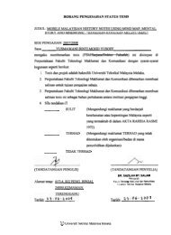
I hereby declared that this report is a result of my own work except for the<br />
excerpts that have been cited clearly their references.”<br />
Signature : ………………………………………………<br />
Name : Ahmad Firdaus Bin Mohammad Mohsin<br />
Date : 06 / 04 / 2010<br />
ii
For my beloved father and mother<br />
Mohammad Mohsin Bin Hj Mohd Sidek and Noor Riza Binti Hj Ahamad<br />
In appreciation of supported and understanding.<br />
iii
ACKNOWLEDGEMENTS<br />
Alhamdulillah, praise be to Allah S.W.T, the Cherisher and Sustainer of world,<br />
most Gracious, most Merciful Lord. Praise be to Allah S.W.T for enabling me to<br />
completed this final year bachelor degree project.<br />
I would like to thank advisor, En Herdey Rusnandy as my supervisor, for his<br />
invaluable help, support and ideas to me through achieving my goals on “Projek Sarjana<br />
Muda 2”. Her countless contributions in this project will remind forever in my mind.<br />
During the completion, I had collaborated with many colleagues for whom I<br />
have great regards and I want to extend my warmest thanks to all those who helped<br />
me with my work especially house mate.<br />
Finally, I would like to honor my parent, for supporting me steadfastly and<br />
their appreciated advice through my project completion.<br />
iv
ABSTRACT<br />
Study conducted in this Project Sarjana Muda (PSM) is about automotive chassis<br />
electrical system and prepare the specific design of automotive training panel board, that<br />
the panel board can be use for teaching and learning purposes. Scope of study in this<br />
PSM is design the suitable automotive chassis wiring system for teaching and learning.<br />
Based on the wiring diagram, design the automotive chassis electrical system training<br />
panel board for teaching and learning purposes, following this training panel board will<br />
provide the laboratory sheet to expose the practical training on this project. The main<br />
objective is to design automotive chassis electrical system training board for teaching<br />
and learning purposes.<br />
v
ABSTRAK<br />
Kajian dijalankan dalam Project Sarjana Muda (PSM) ini adakah berkenaan<br />
sistem elektrik kerangka kenderaan untuk menyediakan satu panel latihan automotif,<br />
panel latihan ini boleh digunakan untuk tujuan pengajar dan tujuan pembelajaran. Skop<br />
kajian dalam PSM ini adalah untuk mereka bentuk sistem pendawaian yang mudah<br />
difahami untuk mengajar dan pengajian. Untuk mereka bentuk sistem elektrik kerangka<br />
kenderaan ini adalah berdasarkan gambar rajah pendawaian yang telah dipermudahkan<br />
dan sesuai untuk dijalankan bagi tujuan pembelajaran. Objektif utama PSM ini adalah<br />
mereka bentuk satu penal latihan sistem elektrik kerangka kenderaan bagi tujuan<br />
pembelajaran.<br />
vi
TABLE OF CONTENT<br />
CHAPTER TITLE PAGE<br />
PREFACE ii<br />
DEDICATION iv<br />
ACKNOWLEDGEMENT v<br />
ABSTRAK vi<br />
ABSTRACT vii<br />
TABLE OF CONTENT viii<br />
LIST OF TABLE x<br />
LIST OF FIGURE xi<br />
LIST OF SYMBOL xii<br />
1 INTRODUCTION<br />
1.1 Background 1<br />
1.2 Objective 1<br />
1.3 Scope 2<br />
1.4 Problem statement 2<br />
2 LITERATURE REVIEW<br />
2.1 Introduction 3<br />
2.2 Power Sources on Car 3<br />
2.3 Controls 5<br />
2.4 Circuit Protection Devices 10<br />
2.5 An overview of Automobile Lighting System 11<br />
2.6 Conductors and Insulators 14<br />
2.7 Direct Current (DC) 15<br />
2.8 Alternating Current (AC) 16<br />
vii
2.9 Factors that affect resistance 18<br />
2.1 Theory Calculation 18<br />
2.11 Complete electrical circuit 21<br />
Research from available product 23<br />
Sample Wiring Diagram 25<br />
3 METHODOLOGY<br />
3.1 Introduction 34<br />
Flow chart 35<br />
3.2 1 st Phase<br />
(design a suitable automotive chassis electrical wiring system)<br />
3.2.1 Head Light and Parking Light system 36<br />
3.2.2 Turn Signal system 38<br />
3.2.3 Reverse Light system 40<br />
3.2.4 Brake Light system 41<br />
3.2.5 Horn system 42<br />
3.2.6 Wiper and Washer system 43<br />
3.2.7 Fuel Gauge System 44<br />
3.3 2 nd phase (design the training panel board and frame) 47<br />
3.3.1 Design frame and the panel board 48<br />
3.3.2 Analysis 48<br />
3.4 3 rd phase (Prepare the lab sheet for practical training) 49<br />
4 RESULT AND DISCUSSION<br />
4.1 Hardware Design 50<br />
4.1.1 Specifications: 57<br />
4.2 Costing analysis 58<br />
4.2.3 Cost Analysis for Panel Board Component: 60<br />
4.2.4 Frame type selection. 61<br />
4.2.5 Total Costing Analysis. 61<br />
4.2.6 Cost comparison with available product market. 61<br />
36<br />
viii
4.3 Finite Element Analysis (FEA). 62<br />
4.3.1 Stress analysis of frame 62<br />
4.4 Wiring Calculation 65<br />
4.5 Laboratory Sheet 75<br />
5 5.1 CONCLUSION 106<br />
5.2 RECOMANDATION<br />
REFERENCE<br />
APPENDIX 109<br />
107<br />
108<br />
ix
TABLE<br />
4.1<br />
4.2<br />
4.3<br />
4.4<br />
LIST OF TABLES<br />
TITLE PAGES<br />
List of material quantity Aluminum Frame 58<br />
List of material quantity Stainless Steel Frame 58<br />
Quotation from MIESTER TECHNOLOGY (M) SDN. BHD. 59<br />
Cost Analysis for Panel Board Component 60<br />
x
LIST OF FIGURE<br />
FIGURE TITLE PAGE<br />
1 Power supply 12 VDC 4<br />
2 Alternator 5<br />
3 Type of switch 7<br />
4 Relay 8<br />
5 Solenoids 9<br />
6 Fuse 10<br />
7 Head Lamp 11<br />
8 Tail Lights 12<br />
9 Side Light 13<br />
10 DC displayed as a scope pattern 16<br />
11 DC displayed as a scope pattern 17<br />
12 Table Resistivity values at room temperature 22<br />
13 Model ES-ECP-T 25<br />
14 Model ES3B 26<br />
15 (Lighting circuit schematic)<br />
27<br />
16 A common turn signal system 28<br />
17 A common brake light system 29<br />
18 Windshield wiper circuit use TIMER 30<br />
19 common power window circuit 31<br />
20 Figure 20: A common fuel gauge system 33<br />
21 A common fuel gauge system 34<br />
22 Horn circuit system 35<br />
3.1 Flow chart project 37<br />
3.2 Head Light and Small Light System circuit 39<br />
xi
3.3 Turn Signal Light System circuit 40<br />
3.4 Reverse Light System circuit 42<br />
3.5 Brake Light System circuit 43<br />
3.6 Horn System circuit 44<br />
3.7 Wiper & Washer System circuit 45<br />
3.8 Fuel Gauge System circuit 46<br />
3.9 Frame of Automotive Chassis Electrical System Training Board 48<br />
4.1 Automotive Chassis Electrical System Training Board 50<br />
4.2 Panel Combination Switch 52<br />
4.3 Panel Ammeter, Volt Meter & Timer 53<br />
4.4 Panel Ignition, brake & reverse switch witch indicator 53<br />
4.5 Panel Fuel Gauge Meter & Fuel Sending Unit 54<br />
4.6 Panel Horn 54<br />
4.7 Panel Rear Tail Light Left & Right 55<br />
4.8 Panel Washer Pump & Wiper Motor 55<br />
4.9 Panel Relay Grouping 56<br />
4.1 Panel Fuse Box 56<br />
4.11 Panel Head Light Left & Right 56<br />
4.12 Panel Front Signal Left & Right 56<br />
4.13 Five Level Mobile floor Frame 57<br />
4.14 Measure Inertia on Five Level Mobile floor Frame 63<br />
4.15 Von Mises Stress of Five Level Mobile floor Frame 63<br />
4.16 Translational displacement of Five Level Mobile floor Frame 64<br />
4.17 Head Light Wiring Simplified 65<br />
4.18 Small Light Conditions 65<br />
4.19 Head Light (LOW) Condition 66<br />
4.2 Head Light (HIGH) Condition 66<br />
4.21 Simplified Wiring Signal Light Left & Right 68<br />
4.22 Hazard Light Condition 68<br />
4.23 Reverse Light Conditions 70<br />
4.<strong>24</strong> Brake light conditions. 71<br />
xii
4.25 Horn condition. 72<br />
4.26 Horn simplified. 72<br />
4.27 Wiper (LOW) condition 73<br />
4.28 Wiper (HIGH) condition 73<br />
4.29 Wiper (HIGH) condition 73<br />
4.5.1 Head Light and Small Light system circuit 78<br />
4.5.2 Head Light and Small Light system connection board 79<br />
4.5.3 Head Light and Small Light system connection board (Answer) 80<br />
4.5.4 Turn signal system circuit 83<br />
4.5.5 Turn signal system circuit connection board 84<br />
4.5.6 Turn signal system circuit connection board (Answer) 85<br />
4.5.7 Reverse system circuit 87<br />
4.5.8 Reverse system circuit connection board 88<br />
4.5.9 Reverse system circuit connection board (Answer) 89<br />
4.5.10 Brake system circuit 91<br />
4.5.11 Brake system circuit connection board 92<br />
4.5.12 Brake system circuit connection board (Answer) 93<br />
4.5.13 Horn system circuit 95<br />
4.5.14 Horn system circuit connection board 96<br />
4.5.15 Horn system circuit connection board (Answer) 97<br />
4.5.16 Fuel Gauge system circuit 99<br />
4.5.17 Fuel Gauge system circuit connection board 100<br />
4.5.18 Fuel Gauge system circuit connection board (Answer) 101<br />
4.5.19 Wiper & Washer system circuit 103<br />
4.5.20 Wiper & Washer system circuit connection board 104<br />
4.5.21 Wiper & Washer system circuit connection board (Answer) 105<br />
xiii
V = Voltage<br />
R = Resistance<br />
I = Current resistance<br />
P = Power<br />
S.F = Safety Factor<br />
L = Left<br />
R = Right<br />
DC = Direct Current<br />
AC = Alternating Current<br />
r = Resistivity<br />
ρ = Resistivity of material<br />
HL = Head Light<br />
FL = Front Left<br />
RL = Rear Left<br />
FR = Front Right<br />
RR = Rear Right<br />
LB = Left Brake<br />
RB = Right Brake<br />
HI = High<br />
LO = Low<br />
B+ = Batteries Positive<br />
E = Ground<br />
LIST OF SYMBOLS<br />
xiv
LIST OF APENDIX<br />
APENDIX TITLE PAGE<br />
A Design dimension of electrical panel board & frame beam 107-127<br />
B CATIA V5 R16 (Stress Analysis) 128-134<br />
C Wiring References 135-END<br />
xv
1.1 Project Background<br />
CHAPTER 1<br />
INTRODUCTION<br />
The Automotive Electrical Training Board System is designed to realistically<br />
simulate the electrical system on an automobile. The unit consists of a number of<br />
modular demonstration panels, which are mounted on a wheeled stand that contains a<br />
power source and component connecting cables. The components featured are real<br />
original parts as commonly used in automobile typically produced by the major car or<br />
component manufacturers. This system can be used in the classroom as a demonstration<br />
unit to show students various types of wiring and to familiarize them with typical car<br />
electrical systems. Also it can be used as a trainer with the student performing actual<br />
wiring exercises with the various components. The Original components are mounted on<br />
clear Acrylic plastic panels that allow high visibility of all parts and wiring. Connection<br />
of the components is easily accomplished by using the cables with stackable plugs that<br />
are provided. A 12 Volt DC automobile batteries was used as a power supplied on this<br />
automotive chassis electrical system training panel board.<br />
1.2 Objective<br />
To design automotive chassis electrical system training board for teaching and<br />
learning purpose.<br />
1
1.3 Scope<br />
Design training panel board<br />
1. Design automotive chassis electrical wiring system for teaching and learning<br />
2. Create lab sheet for practical training<br />
1.4 Problem Statement<br />
The real automotive electrical system on automobile is difficult to understand<br />
because of the automobile that is manufactured is for commercial purposes, so the<br />
electrical system that is currently used by automobiles are hidden and complicated. The<br />
problem is to create and study automotive electrical system.<br />
The study is to understand the principle electrical system of an automobile<br />
chassis, and then transfer it into ‘Training Panel Board’ which is currently not available<br />
in UTeM. The transfer process of the system must base on the suitable electrical wiring<br />
system circuit design which is similar to chassis electrical system that is used on<br />
automobile and facilitate for teaching and learning purpose.<br />
The aim is to conduct a working experiment or practical training based on<br />
automobile chassis electrical system that can be used on this training panel board which<br />
is not available in UTeM for Automotive Engineering student.<br />
The other task is to create lab sheet for practical training to fulfill this automotive<br />
chassis electrical system training board for experiment.<br />
With that, the system can be used in the classroom as a demonstration unit to<br />
show students various types of wiring and to familiarize them with typical car electrical<br />
systems. Also it can be used as a trainer with the student performing actual wiring<br />
exercises with the various components.<br />
2
2.1 Introduction<br />
CHAPTER 2<br />
LITERATURE REVIEW<br />
A literature search was performed to study, design and analysis the chassis<br />
electrical system for automobile/car. It also includes the investigation of what other have<br />
done in this area. This study includes the areas of electrical and electronic as a guide to<br />
design the suitable automobile electrical circuit and automotive chassis electrical system<br />
training board.<br />
Modern automobiles rely on a wide variety of electrical / electronic components<br />
and systems to operate properly. Electricity plays a major role in the proper functioning<br />
of the engine, transmission, even brakes and suspension systems in many cases. A<br />
fundamental knowledge of how electricity works is important for any person associated<br />
with the automobile studies.<br />
2.2 Power Sources on Car<br />
Two power sources are used on vehicles. When the engine is not running or is<br />
being started, the battery provides power. When the engine is running, the alternator<br />
provides for the vehicle’s loads and for recharging the battery.<br />
3
Battery<br />
The battery is the primary “source” of electrical energy on vehicles when the<br />
engine is not running or is being started. It uses an electrochemical reaction to change<br />
chemical energy for starting, ignition, and charging, lighting, and accessories.<br />
Normally all car like Proton, Toyota, and ect vehicle use a 12-volt battery. Batteries<br />
have polarity markings, the larger (thicker) terminal is marked “plus” (+) , the other<br />
terminal is marked “minus” (-) . Correct polarity is important; components can be<br />
damaged if the battery is connected backwards.<br />
Figure 1: 12 VDC Power Supply<br />
(Source: www.wikipedia.com / electrical component)<br />
4
Alternator<br />
The alternator is the heart of the vehicle’s electrical system when the engine is<br />
running. It uses electromagnetism to charge some of the engine’s mechanical energy into<br />
electrical energy for powering the vehicle’s loads and for charging the battery. Currently<br />
all car alternators are rated by amps of current output. It’s within 40 to 80 amps.<br />
2.3 Controls<br />
Figure 2: Alternator<br />
(Source: www.wikipedia.com / electrical component)<br />
Control devices used in electrical circuits on many type of vehicle include a<br />
variety of switches, relay, and solenoids. Electronic control devices include capacitors,<br />
diodes, and transistors. Controls are needed to start, stop, or redirect current flow. Most<br />
switches require physical movement for operation, relays and solenoids are operated<br />
with electromagnetism, electronic controls are operated electrically.<br />
5
Switches<br />
Switches are the most common circuit control device. They usually have two or<br />
more sets of contacts. Opening the contacts is called “opening” or breaking the circuit,”<br />
while closing the contacts is called “closing” or “making” the circuit.”Poles” refer to the<br />
number of input circuit terminals. Throws refer to the number of output circuits. Such<br />
switches are referred to as SPST (single-pole, single-throw), SPDT (single-pole, doublethrow),<br />
and MPMT (multiple-pole, multiple-throw).<br />
The various types of switches include:<br />
Hinged pawl - a simple SPST switch to make or break a circuit.<br />
Momentary contact – another SPST switch, normally open or closed, which makes or<br />
breaks the circuit when pressed, typically used for the horn switch.<br />
SPDT – one wire in, two wire out, commonly used in high-beam / low-beam headlamp<br />
circuits.<br />
MPMT – movable contacts are linked to sets of output terminals, may be used for the<br />
transmission neutral start switch.<br />
Mercury switch – liquid mercury flows between contacts to make circuit, commonly<br />
used to turn engine compartment and trunk lamp on and off.<br />
Temperature-sensitive switch – a bimetal element bends when heated to make contacts<br />
completing a circuit or to break contact opening a circuit. The same principle is also<br />
used in time-delay switches and flashers.<br />
6
Figure 3: Type of switches<br />
(Source: www.wikipedia.com / electrical component)<br />
7
Relay<br />
A relay is simply a remote-control switch, which uses a small amount of current<br />
to control a large amount of current. A typical relay has a control circuit and a power<br />
circuit. The control circuit is fed current by the power source, and the current flows<br />
through a switch and an electromagnetic coil to ground. The power circuit is also fed<br />
current from the power source and the current flows to an armature which can be<br />
attracted by the magnetic force on the coil.<br />
In operation, when the control circuit switch is open, no current flow to the relay.<br />
The coil is not energized, the contacts are open, and no power goes to the load. When<br />
the control circuit switch is closed, however, current flows to the relay and energizes the<br />
coil. The resulting magnetic field pulls the armature down, closing the contacts and<br />
allowing power to the load. Currently many relays are used on automobile for<br />
controlling high current in one circuit with low current in another circuit.<br />
Figure 4: Relay<br />
(Source: www.google.com / electrical component)<br />
8