Effect of Self Weight on a Cantilever Beam - University of Alberta
Effect of Self Weight on a Cantilever Beam - University of Alberta
Effect of Self Weight on a Cantilever Beam - University of Alberta

Create successful ePaper yourself
Turn your PDF publications into a flip-book with our unique Google optimized e-Paper software.
<strong>University</strong> <str<strong>on</strong>g>of</str<strong>on</strong>g> <strong>Alberta</strong> ANSYS Tutorials - www.mece.ualberta.ca/tutorials/ansys/IT/Density/Density.html<br />
<str<strong>on</strong>g>Effect</str<strong>on</strong>g> <str<strong>on</strong>g>of</str<strong>on</strong>g> <str<strong>on</strong>g>Self</str<strong>on</strong>g> <str<strong>on</strong>g>Weight</str<strong>on</strong>g> <strong>on</strong> a <strong>Cantilever</strong> <strong>Beam</strong><br />
Introducti<strong>on</strong><br />
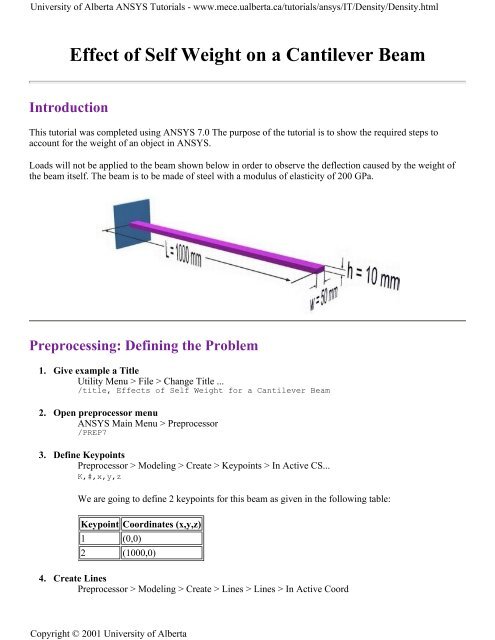
This tutorial was completed using ANSYS 7.0 The purpose <str<strong>on</strong>g>of</str<strong>on</strong>g> the tutorial is to show the required steps to<br />
account for the weight <str<strong>on</strong>g>of</str<strong>on</strong>g> an object in ANSYS.<br />
Loads will not be applied to the beam shown below in order to observe the deflecti<strong>on</strong> caused by the weight <str<strong>on</strong>g>of</str<strong>on</strong>g><br />
the beam itself. The beam is to be made <str<strong>on</strong>g>of</str<strong>on</strong>g> steel with a modulus <str<strong>on</strong>g>of</str<strong>on</strong>g> elasticity <str<strong>on</strong>g>of</str<strong>on</strong>g> 200 GPa.<br />
Preprocessing: Defining the Problem<br />
1. Give example a Title<br />
Utility Menu > File > Change Title ...<br />
/title, <str<strong>on</strong>g>Effect</str<strong>on</strong>g>s <str<strong>on</strong>g>of</str<strong>on</strong>g> <str<strong>on</strong>g>Self</str<strong>on</strong>g> <str<strong>on</strong>g>Weight</str<strong>on</strong>g> for a <strong>Cantilever</strong> <strong>Beam</strong><br />
2. Open preprocessor menu<br />
ANSYS Main Menu > Preprocessor<br />
/PREP7<br />
3. Define Keypoints<br />
Preprocessor > Modeling > Create > Keypoints > In Active CS...<br />
K,#,x,y,z<br />
We are going to define 2 keypoints for this beam as given in the following table:<br />
Keypoint Coordinates (x,y,z)<br />
1 (0,0)<br />
2 (1000,0)<br />
4. Create Lines<br />
Preprocessor > Modeling > Create > Lines > Lines > In Active Coord<br />
Copyright © 2001 <strong>University</strong> <str<strong>on</strong>g>of</str<strong>on</strong>g> <strong>Alberta</strong>
<strong>University</strong> <str<strong>on</strong>g>of</str<strong>on</strong>g> <strong>Alberta</strong> ANSYS Tutorials - www.mece.ualberta.ca/tutorials/ansys/IT/Density/Density.html<br />
L,1,2<br />
Create a line joining Keypoints 1 and 2<br />
5. Define the Type <str<strong>on</strong>g>of</str<strong>on</strong>g> Element<br />
Preprocessor > Element Type > Add/Edit/Delete...<br />
For this problem we will use the BEAM3 (<strong>Beam</strong> 2D elastic) element. This element has 3 degrees <str<strong>on</strong>g>of</str<strong>on</strong>g><br />
freedom (translati<strong>on</strong> al<strong>on</strong>g the X and Y axes, and rotati<strong>on</strong> about the Z axis).<br />
6. Define Real C<strong>on</strong>stants<br />
Preprocessor > Real C<strong>on</strong>stants... > Add...<br />
In the 'Real C<strong>on</strong>stants for BEAM3' window, enter the following geometric properties:<br />
i. Cross-secti<strong>on</strong>al area AREA: 500<br />
ii. Area moment <str<strong>on</strong>g>of</str<strong>on</strong>g> inertia IZZ: 4166.67<br />
iii. Total beam height: 10<br />
This defines a beam with a height <str<strong>on</strong>g>of</str<strong>on</strong>g> 10 mm and a width <str<strong>on</strong>g>of</str<strong>on</strong>g> 50 mm.<br />
7. Define Element Material Properties<br />
Preprocessor > Material Props > Material Models > Structural > Linear > Elastic > Isotropic<br />
In the window that appears, enter the following geometric properties for steel:<br />
i. Young's modulus EX: 200000<br />
ii. Poiss<strong>on</strong>'s Ratio PRXY: 0.3<br />
8. Define Element Density<br />
Preprocessor > Material Props > Material Models > Structural > Linear > Density<br />
In the window that appears, enter the following density for steel:<br />
i. Density DENS: 7.86e-6<br />
9. Define Mesh Size<br />
Preprocessor > Meshing > Size Cntrls > ManualSize > Lines > All Lines...<br />
For this example we will use an element edge length <str<strong>on</strong>g>of</str<strong>on</strong>g> 100mm.<br />
10. Mesh the frame<br />
Preprocessor > Meshing > Mesh > Lines > click 'Pick All'<br />
Soluti<strong>on</strong> Phase: Assigning Loads and Solving<br />
1. Define Analysis Type<br />
Soluti<strong>on</strong> > Analysis Type > New Analysis > Static<br />
ANTYPE,0<br />
Copyright © 2001 <strong>University</strong> <str<strong>on</strong>g>of</str<strong>on</strong>g> <strong>Alberta</strong>
<strong>University</strong> <str<strong>on</strong>g>of</str<strong>on</strong>g> <strong>Alberta</strong> ANSYS Tutorials - www.mece.ualberta.ca/tutorials/ansys/IT/Density/Density.html<br />
2. Apply C<strong>on</strong>straints<br />
Soluti<strong>on</strong> > Define Loads > Apply > Structural > Displacement > On Keypoints<br />
3. Define Gravity<br />
Fix keypoint 1 (ie all DOF c<strong>on</strong>strained)<br />
It is necessary to define the directi<strong>on</strong> and magnitude <str<strong>on</strong>g>of</str<strong>on</strong>g> gravity for this problem.<br />
Select Soluti<strong>on</strong> > Define Loads > Apply > Structural > Inertia > Gravity...<br />
The following window will appear. Fill it in as shown to define an accelerati<strong>on</strong> <str<strong>on</strong>g>of</str<strong>on</strong>g> 9.81m/s 2 in the y<br />
directi<strong>on</strong>.<br />
Note: Accelerati<strong>on</strong> is defined in terms <str<strong>on</strong>g>of</str<strong>on</strong>g> meters (not 'mm' as used throughout the problem). This is<br />
because the units <str<strong>on</strong>g>of</str<strong>on</strong>g> accelerati<strong>on</strong> and mass must be c<strong>on</strong>sistent to give the product <str<strong>on</strong>g>of</str<strong>on</strong>g> force units<br />
(Newt<strong>on</strong>s in this case). Also note that a positive accelerati<strong>on</strong> in the y directi<strong>on</strong> stimulates gravity in<br />
the negative Y directi<strong>on</strong>.<br />
There should now be a red arrow pointing in the positive y directi<strong>on</strong>. This indicates that an<br />
accelerati<strong>on</strong> has been defined in the y directi<strong>on</strong>.<br />
DK,1,ALL,0,<br />
ACEL,,9.8<br />
The applied loads and c<strong>on</strong>straints should now appear as shown in the figure below.<br />
Copyright © 2001 <strong>University</strong> <str<strong>on</strong>g>of</str<strong>on</strong>g> <strong>Alberta</strong>
<strong>University</strong> <str<strong>on</strong>g>of</str<strong>on</strong>g> <strong>Alberta</strong> ANSYS Tutorials - www.mece.ualberta.ca/tutorials/ansys/IT/Density/Density.html<br />
4. Solve the System<br />
Soluti<strong>on</strong> > Solve > Current LS<br />
SOLVE<br />
Postprocessing: Viewing the Results<br />
1. Hand Calculati<strong>on</strong>s<br />
Hand calculati<strong>on</strong>s were performed to verify the soluti<strong>on</strong> found using ANSYS:<br />
The maximum deflecti<strong>on</strong> was shown to be 5.777mm<br />
2. Show the deformati<strong>on</strong> <str<strong>on</strong>g>of</str<strong>on</strong>g> the beam<br />
General Postproc > Plot Results > Deformed Shape ... > Def + undef edge<br />
PLDISP,2<br />
Copyright © 2001 <strong>University</strong> <str<strong>on</strong>g>of</str<strong>on</strong>g> <strong>Alberta</strong>
<strong>University</strong> <str<strong>on</strong>g>of</str<strong>on</strong>g> <strong>Alberta</strong> ANSYS Tutorials - www.mece.ualberta.ca/tutorials/ansys/IT/Density/Density.html<br />
As observed in the upper left hand corner, the maximum displacement was found to be 5.777mm. This is<br />
in agreement with the theortical value.<br />
Command File Mode <str<strong>on</strong>g>of</str<strong>on</strong>g> Soluti<strong>on</strong><br />
The above example was solved using a mixture <str<strong>on</strong>g>of</str<strong>on</strong>g> the Graphical User Interface (or GUI) and the command<br />
language interface <str<strong>on</strong>g>of</str<strong>on</strong>g> ANSYS. This problem has also been solved using the ANSYS command language<br />
interface that you may want to browse. Open the file and save it to your computer. Now go to 'File > Read<br />
input from...' and select the file.<br />
Copyright © 2001 <strong>University</strong> <str<strong>on</strong>g>of</str<strong>on</strong>g> <strong>Alberta</strong>