building the hasegawa 1/32 scale p-47d - mike ashey productions ...
building the hasegawa 1/32 scale p-47d - mike ashey productions ...
building the hasegawa 1/32 scale p-47d - mike ashey productions ...

You also want an ePaper? Increase the reach of your titles
YUMPU automatically turns print PDFs into web optimized ePapers that Google loves.
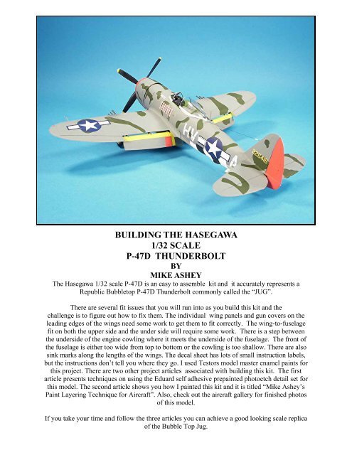
BUILDING THE HASEGAWA<br />
1/<strong>32</strong> SCALE<br />
P-47D THUNDERBOLT<br />
BY<br />
MIKE ASHEY<br />
The Hasegawa 1/<strong>32</strong> <strong>scale</strong> P-47D is an easy to assemble kit and it accurately represents a<br />
Republic Bubbletop P-47D Thunderbolt commonly called <strong>the</strong> “JUG”.<br />
There are several fit issues that you will run into as you build this kit and <strong>the</strong><br />
challenge is to figure out how to fix <strong>the</strong>m. The individual wing panels and gun covers on <strong>the</strong><br />
leading edges of <strong>the</strong> wings need some work to get <strong>the</strong>m to fit correctly. The wing-to-fuselage<br />
fit on both <strong>the</strong> upper side and <strong>the</strong> under side will require some work. There is a step between<br />
<strong>the</strong> underside of <strong>the</strong> engine cowling where it meets <strong>the</strong> underside of <strong>the</strong> fuselage. The front of<br />
<strong>the</strong> fuselage is ei<strong>the</strong>r too wide from top to bottom or <strong>the</strong> cowling is too shallow. There are also<br />
sink marks along <strong>the</strong> lengths of <strong>the</strong> wings. The decal sheet has lots of small instruction labels,<br />
but <strong>the</strong> instructions don’t tell you where <strong>the</strong>y go. I used Testors model master enamel paints for<br />
this project. There are two o<strong>the</strong>r project articles associated with <strong>building</strong> this kit. The first<br />
article presents techniques on using <strong>the</strong> Eduard self adhesive prepainted photoetch detail set for<br />
this model. The second article shows you how I painted this kit and it is titled “Mike Ashey’s<br />
Paint Layering Technique for Aircraft”. Also, check out <strong>the</strong> aircraft gallery for finished photos<br />
of this model.<br />
If you take your time and follow <strong>the</strong> three articles you can achieve a good looking <strong>scale</strong> replica<br />
of <strong>the</strong> Bubble Top Jug.
The step between <strong>the</strong> cowling and <strong>the</strong> fuselage will be too<br />
noticeable if it is not fixed. The solution is to slightly extend<br />
<strong>the</strong> depth of <strong>the</strong> cowling.<br />
The sink marks are on all four wings sections and will need<br />
to be sanded out and <strong>the</strong>n <strong>the</strong> plastic will need to be polished<br />
with 0000 steel wool.<br />
There is a gap between <strong>the</strong> canopy windscreen and <strong>the</strong><br />
fuselage and it can easily be filled with a strip of<br />
.010 inch plastic.<br />
The cockpit is well detailed, but I used <strong>the</strong> Eduard prepainted<br />
self adhesive photoetch detail set. There is a separate article<br />
on <strong>building</strong> up <strong>the</strong> cockpit with this detail set.<br />
Here is <strong>the</strong> prepainted photoetch sheet. The second photoetch sheet contains lots of small detail<br />
parts to fur<strong>the</strong>r enhance <strong>the</strong> cockpit. I like to use <strong>the</strong>se parts<br />
in combination with kit parts to achieve better results.
The photoetch seat is pretty good, but I used <strong>the</strong> kits seat . I thinned <strong>the</strong> back and sides of <strong>the</strong> plastic and I used a figure<br />
eight motion to help ensure that <strong>the</strong> plastic<br />
was thinned evenly<br />
I attached <strong>the</strong> photoetch detail parts to <strong>the</strong> kits seat. The<br />
kits seat is a bit stronger than <strong>the</strong> photoetch seat.<br />
The prepainted photoetch placards require that some surface<br />
details in <strong>the</strong> cockpit be sanded off.<br />
Next I added <strong>the</strong> photoetch details to <strong>the</strong> cockpit floor.<br />
The photoetch set had a gun sight, but I modified <strong>the</strong> kit’s<br />
part instead. I drilled out <strong>the</strong> holes in <strong>the</strong> framing and I also<br />
drilled out a base for <strong>the</strong> gun sight reflective lens. I used my<br />
Waldron punch tool to make a lens.
The interior parts are painted with Testors green zinc<br />
chromate. The metal edges were dry brushed with silver and<br />
<strong>the</strong> canvas and lea<strong>the</strong>r were drybrushed with flat white. I<br />
used several different shades of <strong>the</strong> interior color.<br />
To protect photoetch parts that need to be bent I attached<br />
small strips of masking tape to <strong>the</strong> faces of <strong>the</strong> flat nosed<br />
pliers. I use a round toothpick with a flat end and a tiny<br />
piece of masking tape attached to pick up small parts.<br />
The seat belts are draped over <strong>the</strong> frame and <strong>the</strong> seats. Attach<br />
<strong>the</strong>m with super glue and any overflow or smeared glue can<br />
be hidden by applying a coat of Testors clear flat.<br />
I used small strips of masking tape to detail paint parts on <strong>the</strong><br />
side panels of <strong>the</strong> cockpit. Careful paint mixing and thinning<br />
will give you great results when airbrushing <strong>the</strong>se<br />
small parts.<br />
Note how <strong>the</strong> combination of painting and <strong>the</strong><br />
photoetch parts greatly enhance <strong>the</strong> appearance of<br />
<strong>the</strong> cockpit.<br />
Note how <strong>the</strong> reflective lens enhances <strong>the</strong> appearance of <strong>the</strong><br />
gun sight. Eduard’s prepainted console’s are outstanding<br />
and <strong>the</strong>re is no way to achieve this level of detail with paint.
One last detail that I added was console wiring. I used brass<br />
beading wire and nylon sewing thread colored with<br />
indelible markers.<br />
To prevent <strong>the</strong> wings from flexing I laminated .020 inch<br />
strips to <strong>the</strong> inside areas using super glue.<br />
To get <strong>the</strong> wings to fit correctly against <strong>the</strong> fuselage you<br />
have to remove this raised surface on <strong>the</strong> ends of <strong>the</strong> landing<br />
gear wells.<br />
I had to add strips of plastic to <strong>the</strong> sides of <strong>the</strong> wing panel to<br />
get a tight fit.<br />
I assembled <strong>the</strong> landing gear wells with masking tape and<br />
<strong>the</strong>n I ran beads of super glue along <strong>the</strong> seam lines.<br />
The gun covers did not fit well on <strong>the</strong> leading edges of <strong>the</strong><br />
wings and it took several coats of super glue and iterations of<br />
scraping and sanding to get <strong>the</strong>m to contour into <strong>the</strong><br />
wings surface.
I like to attach <strong>the</strong> elevators to <strong>the</strong> fuselage and work on <strong>the</strong><br />
seams before I glue <strong>the</strong> fuselage toge<strong>the</strong>r so I will not<br />
crack a seam.<br />
I laminated .010 inch strips to <strong>the</strong> left and right sides. I<br />
<strong>the</strong>n carefully trimmed <strong>the</strong> plastic and <strong>the</strong>n sanded <strong>the</strong> seam<br />
lines smooth.<br />
While one side fits flush <strong>the</strong> o<strong>the</strong>r side sticks out and will<br />
require careful sanding to get it to contour into <strong>the</strong> surface of<br />
<strong>the</strong> fuselage.<br />
I use masking tape to protect surface detail while sanding<br />
and polishing.<br />
The fit of <strong>the</strong> separate fuselage part which covers <strong>the</strong> engine<br />
super charger needs attention.<br />
This step on <strong>the</strong> aft wing area where it attached to <strong>the</strong><br />
fuselage was a problem. Something was causing <strong>the</strong> wings<br />
to do this.
There is a slight void along <strong>the</strong> seam line, sink marks and a<br />
slight step which will require some scarping to reduce <strong>the</strong><br />
height of <strong>the</strong> plastic.<br />
Now that <strong>the</strong> step is gone. I added several layers of super<br />
glue along <strong>the</strong> seam line.<br />
The plastic was scraped to reduce its height which also got<br />
rid of <strong>the</strong> sink marks. The seam line is getting its last coat of<br />
super glue.<br />
I discovered that <strong>the</strong> tab on <strong>the</strong> inside area of <strong>the</strong> wing where<br />
it connects to <strong>the</strong> fuselage was too high. I removed a section<br />
of it and <strong>the</strong> step on <strong>the</strong> upper aft surface of <strong>the</strong> wing<br />
connection point disappeared.<br />
By modifying <strong>the</strong> wing connection areas I was able to get a<br />
tight fit. After several coats of super glue and careful wet<br />
sanding <strong>the</strong> upper wing areas were finished<br />
I used a sanding stick to work on <strong>the</strong> seam lines on <strong>the</strong> tires.<br />
Wet sanding helps reduce abrasion on <strong>the</strong> plastic<br />
as you sand.
I always check my seam lines with Testors silver paint. To restore <strong>the</strong> tread on <strong>the</strong> tires I use a jewelers saw. Since<br />
<strong>the</strong> right and left sides of <strong>the</strong> tread were still <strong>the</strong>re, I simple<br />
ran <strong>the</strong> saw across <strong>the</strong> surface of <strong>the</strong> tire to connect <strong>the</strong><br />
treads. It took some time, but <strong>the</strong> results were great!<br />
The landing gear needed to be cleaned up. I carefully<br />
scraped off <strong>the</strong> mold lines and trimmed and sanded smooth<br />
<strong>the</strong> tree connection points. I used a Flex-I-File to restore <strong>the</strong><br />
round appearance of <strong>the</strong> landing gear.<br />
To add strength to <strong>the</strong> assembly I also added super glue to<br />
<strong>the</strong> inside seam areas at <strong>the</strong> connection points of <strong>the</strong> panels.<br />
I assembled <strong>the</strong> cowling and <strong>the</strong>n I glued <strong>the</strong> upper panels by<br />
running tiny beads of super glue along <strong>the</strong> seam lines. It took<br />
me several tries before I got <strong>the</strong> panels to line up correctly<br />
before taping and gluing.<br />
To fix <strong>the</strong> step between <strong>the</strong> cowling and <strong>the</strong> fuselage I<br />
added .030 inch strips to <strong>the</strong> gluing surface of <strong>the</strong> lower<br />
cowling part. This will make <strong>the</strong> cowling slightly longer<br />
from top to bottom.
The lower section was super glued and <strong>the</strong>n <strong>the</strong> surface was<br />
sanded smooth. I also added some strips to <strong>the</strong> step in <strong>the</strong><br />
cowling to close up a small gap created by my modification.<br />
I had to do a little sanding along <strong>the</strong> edges of <strong>the</strong> cowling<br />
and I form fitted it into place. Adding <strong>the</strong> extra plastic solved<br />
<strong>the</strong> step problem between <strong>the</strong> cowling and <strong>the</strong> fuselage.<br />
I marked <strong>the</strong> flap hinges so I would not mix <strong>the</strong>m up, glued<br />
<strong>the</strong>m into place, taped <strong>the</strong> flaps toge<strong>the</strong>r and <strong>the</strong>n<br />
fixed <strong>the</strong> seams.<br />
I slipped a section of .020 inch sheet into <strong>the</strong> inside area of<br />
<strong>the</strong> cowling to close <strong>the</strong> gap between <strong>the</strong> air intake sleeves<br />
and <strong>the</strong> inside bottom of <strong>the</strong> lower cowling.<br />
I cleaned up <strong>the</strong> flap parts and taped <strong>the</strong>m toge<strong>the</strong>r to check<br />
<strong>the</strong> fit.<br />
I restored <strong>the</strong> panel lines on <strong>the</strong> fuselage and <strong>the</strong> wings and<br />
<strong>the</strong>n masked <strong>the</strong> cockpit for painting. I primed <strong>the</strong> model and<br />
checked for flaws in my seam work.
Check out <strong>the</strong> article on my paint layering technique to see<br />
how I painted <strong>the</strong> model. I should have used more green on<br />
<strong>the</strong> upper surface, but I like <strong>the</strong> way it looks.<br />
I masked around <strong>the</strong> areas that needed painting and <strong>the</strong>n I<br />
applied large sections of masking tape to <strong>the</strong> wings and<br />
fuselage to protect <strong>the</strong> surfaces from over spray.<br />
The flaps were painted using my paint layering technique.<br />
There are sharp demarcation lines between <strong>the</strong> colors.<br />
The invasion stripes look crisp, clean and straight especially<br />
<strong>the</strong> fuselage stripes. The landing gear wells and <strong>the</strong> flap<br />
areas still need painting.<br />
Careful masking in combination with good paint mixing and<br />
airbrush technique gives you great results. Check out my<br />
aircraft books for tips and techniques on painting.<br />
The landing gear parts were painted and <strong>the</strong>n assembled. I<br />
added some flat white to <strong>the</strong> flat black for <strong>the</strong> tires so <strong>the</strong>y<br />
would look more like a rubber color. Note how clean <strong>the</strong><br />
assembled landing gear look.
The fuselage, cowling and propeller all got two coats of<br />
Minwax clear gloss polyurethane. Now its time to<br />
start decaling.<br />
I used my Waldron punch tool to make a hole in one of <strong>the</strong><br />
wing decals for <strong>the</strong> wing light.<br />
Each letter on <strong>the</strong> fuselage was carefully positioned to make<br />
sure it was straight and level. Having a gloss surface<br />
allowed me to slide <strong>the</strong> decal around without damaging it.<br />
To help minimize decal silvering I cut out <strong>the</strong> letters<br />
separately and I also removed as much of <strong>the</strong> clear carrier<br />
film as possible.<br />
The kit decals wrinkled up really bad when I applied decal<br />
set solution. They did finally lay down although I had to<br />
press out some of <strong>the</strong> wrinkles. I <strong>the</strong>n applied more<br />
setting solution.<br />
Once all <strong>the</strong> decals were applied I gave <strong>the</strong> model a coat of<br />
Testors clear flat. The paint colors showed through <strong>the</strong> white<br />
areas of <strong>the</strong> insignia decals.
Although <strong>the</strong> clear parts had wing lights, <strong>the</strong> wings were<br />
molded with outlines for <strong>the</strong> lights. I masked off <strong>the</strong>se areas<br />
and <strong>the</strong>n painted <strong>the</strong>m.<br />
The canopy parts were masked with small sections of<br />
masking tape.<br />
I airbrushed <strong>the</strong> interior color first on both sides of <strong>the</strong><br />
clear parts.<br />
When you mask over Testors clear flat it can peel up.<br />
Carefully airbrush a few coats onto <strong>the</strong> effected area and <strong>the</strong>n<br />
give <strong>the</strong> surface around <strong>the</strong> damaged area a few coats to<br />
blend everything in.<br />
I carefully masked <strong>the</strong> inside of <strong>the</strong> canopy windscreen. I<br />
masked <strong>the</strong> entire inside area of <strong>the</strong> canopy except for <strong>the</strong><br />
frame area where it connects to <strong>the</strong> windscreen.<br />
I <strong>the</strong>n masked off <strong>the</strong> interior area and <strong>the</strong>n painted <strong>the</strong><br />
exterior with primer.
The windscreen had a wide gap in <strong>the</strong> front and tiny ones on<br />
<strong>the</strong> sides. I filled <strong>the</strong> gaps with several coats of white glue<br />
and <strong>the</strong>n touched up <strong>the</strong> areas with a detail brush.<br />
I drilled a tiny hole in <strong>the</strong> tail for <strong>the</strong> antenna wire. I used<br />
nylon sewing thread colored with a black indelible marker<br />
for <strong>the</strong> antenna.<br />
The kit is assembled except for <strong>the</strong> engine. The landing gear<br />
had some fit problems that required some careful trimming<br />
and fitting.<br />
The sway braces for <strong>the</strong> drop tank needed to be adjusted<br />
several times before <strong>the</strong>y sat correctly with <strong>the</strong> tank installed.<br />
I also had to drill larger holes in <strong>the</strong> fuselage for <strong>the</strong><br />
positioning pins on <strong>the</strong> parts.<br />
I drilled a tiny hole through a length of .030 inch rod and<br />
slipped <strong>the</strong> thread through it to represent <strong>the</strong> insulator. I<br />
should have made this part smaller.<br />
There were not enough spark plug wire attachment points on<br />
<strong>the</strong> engine’s collector ring so I added some more with .035<br />
inch diameter rod.
I drilled out <strong>the</strong> locations for <strong>the</strong> spark plug wires. I used<br />
soft brass beading wire for <strong>the</strong> spark plug wires. I was a bit<br />
disappointed with <strong>the</strong> kits engine.<br />
The guns were made from .080<br />
inch rod and <strong>the</strong>n drilled out.<br />
The engine parts were all airbrushed and <strong>the</strong> engine was<br />
assembled. I <strong>the</strong>n added <strong>the</strong> spark plug wires. I <strong>the</strong>n<br />
attached <strong>the</strong> engine to <strong>the</strong> cowling, glued <strong>the</strong> cowling onto<br />
<strong>the</strong> fuselage and added <strong>the</strong> propeller.<br />
Proper planning, good assembly, painting and decaling technique combined with patience<br />
can make all <strong>the</strong> difference when you are <strong>building</strong> a kit with as many challenges as this<br />
model had. The addition of Eduard’s prepainted photoetch set really enhanced <strong>the</strong> models<br />
appearance and I am hooked on <strong>the</strong>se detail sets! I should have also<br />
purchased aftermarket decals.