Complete Compiled Specification.pdf - Peck Ormsby Construction
Complete Compiled Specification.pdf - Peck Ormsby Construction
Complete Compiled Specification.pdf - Peck Ormsby Construction

Create successful ePaper yourself
Turn your PDF publications into a flip-book with our unique Google optimized e-Paper software.
SL&A ARCHITECTS<br />
A R C H I T E C T U R E<br />
PLANNING<br />
I N T E R I O R S<br />
634 S 400 WEST<br />
S U I T E 2 0 0<br />
S A L T L A K E C I T Y<br />
U T A H 8 4 1 0 1<br />
T E L E P H O N E :<br />
8 0 1 . 3 2 2 . 5 5 5 0<br />
F A C S I M I L E :<br />
801 . 3 2 2 . 5 5 5 7<br />
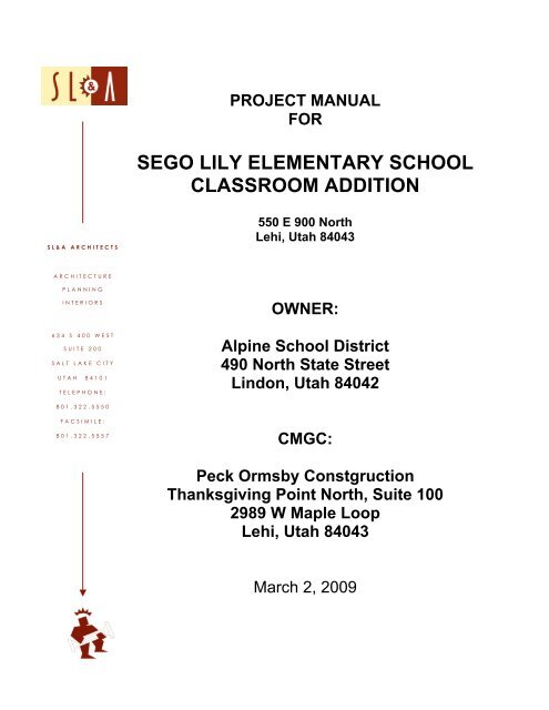
PROJECT MANUAL<br />
FOR<br />
SEGO LILY ELEMENTARY SCHOOL<br />
CLASSROOM ADDITION<br />
550 E 900 North<br />
Lehi, Utah 84043<br />
OWNER:<br />
Alpine School District<br />
490 North State Street<br />
Lindon, Utah 84042<br />
CMGC:<br />
<strong>Peck</strong> <strong>Ormsby</strong> Constgruction<br />
Thanksgiving Point North, Suite 100<br />
2989 W Maple Loop<br />
Lehi, Utah 84043<br />
March 2, 2009
PROJECT MANUAL<br />
TABLE OF CONTENTS<br />
DIVISION 0 – BIDDING AND CONTRACT REQUIREMENTS<br />
Section 00010 – Notice to Subcontractors<br />
Section 00100 – Instructions to Bidders<br />
Section 00300 – Bid Form<br />
Section 00350 – Forms<br />
Section 00500 – Project Schedules<br />
Section 00700 – General Conditions<br />
Section 00800 – Supplementary General Conditions<br />
DIVISION 1 – GENERAL REQUIREMENTS<br />
Section 01010 – Summary of Work<br />
Section 01030 – Alternates<br />
Section 01035 – Modification Procedures<br />
Section 01040 – Project Coordination<br />
Section 01050 – Field Engineering<br />
Section 01090 – Definitions and Standards<br />
Section 01100 – Products and Substitutions<br />
Section 01155 – Application for Payment<br />
Section 01200 – Project Meetings<br />
Section 01300 – Submittals<br />
Section 01400 – Testing and Laboratory Service<br />
Section 01500 – <strong>Construction</strong> Facilities and Temporary Controls<br />
Section 01700 – Contract Closeout<br />
Section 01731 – Cutting and Patching<br />
Section 01740 – Warranties and Bonds<br />
Section 01782 – Operational and Maintenance Data<br />
DIVISION 2 – SITEWORK<br />
Section 02001 – General Site <strong>Construction</strong> Requirements<br />
Section 02002 – Site Clearing<br />
Section 02003 – Earth Moving<br />
Section 02004 – Excavation Support Protections<br />
Section 02005 – Asphalt Paving<br />
Section 02006 – Concrete Paving<br />
Section 02007 – Site Signage<br />
Section 02008 – Water Utility Piping<br />
Section 02009 – Storm Utility Drain Piping<br />
Section 02010 – Subdrainage<br />
Section 02050 – Selective Demolition<br />
Section 02810 – Underground Irrigation Systems<br />
Section 02830 – Fences and Gates<br />
Section 02900 – Landscaping<br />
DIVISION 3 – CONCRETE<br />
Section 03300 – Concrete Work<br />
SEGO LILY ELEMENTARY SCHOOL CLASSROOM ADDITION<br />
TABLE OF CONTENTS TOC - 1
DIVISION 4 – MASONRY<br />
Section 04200 – Unit Masonry<br />
DIVISION 5 – METALS<br />
Section 05120 – Structural Steel<br />
Section 05200 – Steel Joists and Joist Girders<br />
Section 05300 – Steel Deck<br />
Section 05400 – Cold-Formed Metal Framing<br />
Section 05500 – Metal Fabrications<br />
Section 05810 – Expansion Joint Systems<br />
DIVISION 6 – WOOD<br />
Section 06100 – Rough Carpentry<br />
Section 06200 – Finish Carpentry<br />
Section 06402 – Interior Architectural Millwork<br />
DIVISION 7 – THERMAL AND MOISTURE PROTECTION<br />
Section 07210 – Building Insulation<br />
Section 07240 – Exterior Insulation and Finish Systems<br />
Section 07270 – Firestopping<br />
Section 07411 – Manufactured Roof Panels<br />
Section 07430 – Composite Panels<br />
Section 07511 – Built-Up Asphalt Roofing<br />
Section 07542 – Polyvinyl-Chloride (PVC) Roofing<br />
Section 07600 – Flashing and Sheet Metal<br />
Section 07720 – Roof Accessories<br />
Section 07900 – Joint Sealants<br />
DIVISION 8 – DOORS AND WINDOWS<br />
Section 08100 – Hollow Metal Door and Frames<br />
Section 08200 – Wood Doors<br />
Section 08305 – Access Doors<br />
Section 08400 – Aluminum Entrances and Storefronts<br />
Section 08700 – Finish Hardware<br />
Section 08800 – Glass and Glazing<br />
Section 08950 – Insulated Translucent Sandwich Panel Wall/Roof System<br />
DIVISION 9 – FINISHES<br />
Section 09250 – Gypsum Board Assemblies<br />
Section 09300 – Tile<br />
Section 09510 – Acoustical Ceilings<br />
Section 09650 – Resilient Flooring<br />
Section 09680 – Carpet<br />
Section 09900 – Painting<br />
DIVISION 10 – SPECIALTIES<br />
Section 10100 – Visual Display Boards<br />
SEGO LILY ELEMENTARY SCHOOL CLASSROOM ADDITION<br />
TABLE OF CONTENTS TOC - 2
Section 10170 – Solid Phenolic Plastic Toilet Compartments<br />
Section 10350 – Flagpoles<br />
Section 10425 – Signage<br />
Section 10520 – Fire Extinguishers, Cabinets and Accessories<br />
Section 10800 – Toilet and Bath Accessories<br />
DIVISION 11 – EQUIPMENT<br />
Section 11132 – Projection Screens<br />
Section 11451 – Appliances<br />
DIVISION 12 – FURNISHINGS<br />
Section 12492 – 2” Horizontal Aluminum Blinds<br />
Section 12670 – Entrance Mats<br />
DIVISION 13 – SPECIAL CONSTRUCTION<br />
Not Used<br />
DIVISION 14 – CONVEYING SYSTEMS<br />
Not Used<br />
DIVISION 15 – MECHANICAL<br />
Section 15010 – General Provisions<br />
Section 15030 – System Commissioning<br />
Section 15042 – Testing<br />
Section 15043 – Balancing<br />
Section 15050 – Basic Materials & Methods<br />
Section 15180 – Insulation<br />
Section 15400 – Plumbing<br />
Section 15500 – Fire Protection<br />
Section 15700 – Heating-Cooling<br />
Section 15800 – Air Distribution<br />
Section 15900 – Building Management and Control System (BMCS)<br />
DIVISION 16 – ELECTRICAL<br />
Section 16050 – Basic Electrical Materials and Methods<br />
Section 16115 – Cable Tray<br />
Section 16120 – Wires and Cables<br />
Section 16130 – Raceways<br />
Section 16140 – Switches and Receptacles<br />
Section 16425 – Switchboards 600 V & Below<br />
Section 16470 – Panelboards<br />
Section 16475 – Motor Controllers<br />
Section 16478 – Transient Voltage Surge Suppression<br />
Section 16500 – Lighting<br />
Section 16530 – Lighting Controls<br />
Section 16550 – Occupancy Sensed Lighting Control<br />
Section 16723 – Fire Alarm Systems<br />
Section 16760 – Integrated Electronic Communication Network<br />
SEGO LILY ELEMENTARY SCHOOL CLASSROOM ADDITION<br />
TABLE OF CONTENTS TOC - 3
Section 16740 – Telephone and Data Wiring<br />
Section 16771 – Classroom Sound Reinforcement, Projectors and Smartboards<br />
Section 16780 – Television Program Distribution<br />
Section 16781 – Security Intrusion Detection and Access Control System<br />
APPENDIX A<br />
Geotechnical Report<br />
SEGO LILY ELEMENTARY SCHOOL CLASSROOM ADDITION<br />
TABLE OF CONTENTS TOC - 4
DIVISION 0 – BIDDING AND CONTRACT REQUIREMENTS<br />
Section 00010 – Notice to Subcontractors<br />
Section 00100 – Instructions to Bidders<br />
Section 00300 – Bid Form<br />
Section 00350 – Forms<br />
Section 00500 – Project Schedules<br />
Section 00700 – General Conditions<br />
Section 00800 – Supplementary General Conditions<br />
SEGO LILY ELEMENTARY SCHOOL CLASSROOM ADDITION<br />
DIVISION TABLE OF CONTENTS
SECTION 00010 – NOTICE TO SUBCONTRACTORS<br />
A. Notice is hereby given that<br />
<strong>Peck</strong> <strong>Ormsby</strong> <strong>Construction</strong> Company<br />
Thanksgiving Point North, Suite 100<br />
2989 W Maple Loop<br />
Lehi, Utah 84043<br />
Phone 801-766-1700, Fax 801-766-1715<br />
will receive Bid Proposals from subcontractors on or before 2:00 PM, MDT, Thursday, March 26,<br />
2009 for the construction of:<br />
Sego Lily Elementary School Classroom Addition<br />
550 E 900 North<br />
Lehi, Utah<br />
For the following scope of Work:<br />
1. Divisions 2 thru 16.<br />
B. Bids shall be submitted in accordance with Contract Drawings, <strong>Specification</strong>s, Addenda and all other<br />
Contract Documents as prepared by SL&A Architects. Bids may be hand delivered or faxed to the<br />
CM/GC or emailed to juddpeck@peckormsby.com .<br />
C. Alpine School District and <strong>Peck</strong> <strong>Ormsby</strong> <strong>Construction</strong> Company (CM/GC) reserve the right to reject<br />
any and all proposals with or without cause for any reason determined by the District and CMGC, in<br />
its sole subjective determination, to be in the District’s best interest and to waive any bidding<br />
informality. Award or rejection in whole or any part of this project is contingent upon budget.<br />
D. Contract Documents may be examined and copies obtained on or around 12:00 PM, Wednesday,<br />
March 11, 2009, at the office of <strong>Peck</strong> <strong>Ormsby</strong> <strong>Construction</strong>. A $150.00 refundable deposit is required<br />
per each set of Documents. Documents will also be available at the following locations:<br />
1. Intermountain Contractor Plan Rooms<br />
1743 W. Alexander, SLC, Phone 972-4400<br />
313 E. 1200 S, Orem, Phone 224-4333<br />
2. Mountainlands Area Plan Rooms<br />
583 W. 3560 South, Suite 4, SLC, Phone 288-1188<br />
1116 S. State, Orem, Phone 226-2437<br />
1925 W. 5200 South, Roy<br />
3. Sheet Metal Contractor Association<br />
179 W. Haven Ave, South Salt Lake, Phone 486-8449<br />
E. Any questions directed to the Architect during the bidding phase must be faxed to the Architect’s<br />
office (801-322-5557) or emailed (rfisher@slaarch.com).<br />
F. Successful subcontractors will be required to enter into a Contract Agreement with <strong>Peck</strong> <strong>Ormsby</strong><br />
<strong>Construction</strong> Company.<br />
END OF SECTION<br />
SEGO LILY ELEMENTARY SCHOOL CLASSROOM ADDITION MARCH 2, 2009<br />
NOTICE TO SUBCONTRACTORS 00010 - 1
SEGO LILY ELEMENTARY SCHOOL CLASSROOM ADDITION MARCH 2, 2009<br />
NOTICE TO SUBCONTRACTORS 00010 - 2
SECTION 00100 - INSTRUCTIONS TO BIDDERS<br />
1.01 SECURING CONTRACT DOCUMENTS<br />
A. Drawings, specifications and other contract documents may be obtained at the office of the<br />
Contractor by complying with the conditions as stipulated in the “Notice to Subcontractors.”<br />
1.02 PROPOSALS<br />
A. Before submitting a proposal, each bidder shall carefully examine the drawings,<br />
specifications and other contract documents, shall visit the site of work, shall fully inform<br />
himself/herself as to all existing conditions and limitations, and shall include in the proposal<br />
the cost of all items included in the contract.<br />
B. It shall be the responsibility of the bidder to see that his/her proposal is received on or before<br />
the closing time indicated in the “Notice to Subcontractors.” Any proposal received after the<br />
scheduled closing time for receipt of bids shall be returned to the bidder.<br />
C. Each bidder shall inform himself/herself fully of the conditions relating to construction of the<br />
project and the employment of labor thereon. Failure to do so will not relieve a successful<br />
bidder of the obligation to furnish all material and labor necessary to carry out the provisions<br />
of the Contract.<br />
1.03 SCOPE OF WORK<br />
A. The Work consists of the furnishing of all labor, materials, services, equipment and<br />
appliances required for the fabrication, delivery and erection of all items of work.<br />
1.04 WITHDRAWAL OF BID<br />
A. Bids may be withdrawn by the bidder either personally or by written request prior to, but not<br />
after, the time fixed for opening the bids. Bids submitted and opened may not be withdrawn,<br />
and must remain fixed and in force as submitted for a period of forty-five (45) days after the<br />
date for opening the bids.<br />
1.05 INTERPRETATION OF DRAWINGS AND DOCUMENTS<br />
A. If any person contemplating submitting a bid for the proposed Contract is in doubt as to the<br />
true meaning of any part of the drawings, specifications or other proposed Contract<br />
Documents, he/she may submit to the Architect, a written request for an interpretation or<br />
corrections thereof. The person submitting the request will be responsible for its prompt<br />
delivery. Any interpretation or correction of the proposed Documents will be made only by<br />
Addendum duly issued, and a copy of such Addendum will be mailed or delivered to each<br />
person receiving a set of such Documents. The Owner will not be responsible for any oral<br />
instructions of the proposals received other than items which are included in addenda,<br />
additional written instructions or subsequent written change orders.<br />
1. Written requests may be faxed or emailed to SL&A Architects:<br />
a. Fax: (801) 322-5557<br />
b. Email: rfisher@slaarch.com<br />
B. It is the responsibility of each bidder to ascertain that he/she is in possession of a complete<br />
set of Contract Documents by comparing page numbers against indexes. Before submitting<br />
bids, the subcontractor may wish to check with the CMGC or Architect to determine the<br />
status of any addenda or additional instructions. No post-bidding claims of incomplete sets of<br />
drawings, specifications, addenda, etc. will be considered.<br />
C. Should discrepancies appear in the drawings or specifications which are not clarified<br />
or altered by the addenda, then it will be assumed that the subcontractor has bid the<br />
SEGO LILY ELEMENTARY SCHOOL CLASSROOM ADDITION MARCH 2, 2009<br />
INSTRUCTIONS TO BIDDERS 00100 - 1
project using the most expensive method and/or material.<br />
1.06 ADDENDA OR BULLETINS<br />
A. Any addenda or bulletins issued during the time of bidding, or forming a part of the<br />
Documents loaned to the bidder for the preparation of his bid, shall be covered in the bid and<br />
shall be made a part of the Contract.<br />
1.07 AGREEMENT<br />
A. The form of Agreement shall be a Contract between General Contractor and Subcontractor.<br />
1.08 AWARD OR REJECTION OF BIDS<br />
A. The Contract will be awarded to the lowest responsible bidder complying with these<br />
instructions and with the Notice to Subcontractors.<br />
1.09 APPROVAL OF SUBCONTRACTORS<br />
A. The Owner reserves the right to approve all subcontractors whose services may be used by<br />
the General Contractor in prosecution of the work. Such subcontractors may be required to<br />
submit a statement of their financial responsibilities, bonding limit, current workload, and<br />
experience before approval is given.<br />
1.10 EQUAL OPPORTUNITY EMPLOYER<br />
A. Any subcontractor bidding on this project must be an equal opportunity employer and must<br />
agree to abide by all aspects of the following statement:<br />
1. The Contractor agrees to abide by the provisions of Title VI and VII of the Civil Rights<br />
Act of 1964 (42USC2000c) which prohibits discrimination against any employee or<br />
applicant for employment or any applicant or recipient of services on the basis of<br />
race, religion, color or national origin and further agrees to abide by Executive Order<br />
No. 11246 as amended which prohibits discrimination on the basis of sex, 45CFR90<br />
which prohibits discrimination on the basis of age, and Section 504 of the<br />
Rehabilitation Act of 1973; or the Americans with Disabilities Act of 1990<br />
(42USC12101) which prohibits discrimination on the basis of disability. Also,<br />
Contractor agrees to abide by Utah’s Executive Order, dated June 30, 1989, which<br />
prohibits sexual harassment in the work place.<br />
1.11 COST BREAKDOWN<br />
A. The Subcontractor shall, before starting his/her work, submit to the General Contractor, a<br />
cost breakdown showing the cost of various Sub-subcontractors of the work according to<br />
specification headings. The General Contractor will then submit to the Architect a breakdown<br />
of the trades, equaling the contract price. This breakdown will be used as the basis for the<br />
payment of monthly estimates.<br />
1.12 PAYMENT FOR STORED MATERIALS<br />
A. Due to the price volatility of some materials and products, the Owner will consider payment<br />
for early delivery of materials delivered to the Project Site and securely stored at the site.<br />
Subcontractors are requested to note on their bids, any discount in bid if an early payment is<br />
made, with the understanding that the material must be on site prior to payment.<br />
1.13 INSURANCE POLICIES<br />
SEGO LILY ELEMENTARY SCHOOL CLASSROOM ADDITION MARCH 2, 2009<br />
INSTRUCTIONS TO BIDDERS 00100 - 2
A. Prior to signing the contract, the Subcontractor shall obtain Contractor’s Liability Insurance<br />
and other policies as stipulated in the General Conditions. Such policies shall be properly<br />
executed and shall have the approval of the Owner before proceeding.<br />
B. Fire insurance shall be secured by the Board of Education.<br />
1.13 TIME OF COMPLETION<br />
A. The Subcontractor agrees to complete the work required by the Contact, per the included<br />
schedule and as follows:<br />
1. All work on the Sego Lil Elementary School Classroom Addition in Lehi, Utah shall be<br />
completed per the CMGC Contract Agreement with the Owner.<br />
Date of Substantial Completion: December 31, 2009.<br />
B. The completion of work means total completion with no outstanding punch list items.<br />
1.14 MATERIALS AND SUBSTITUTIONS<br />
A. Prior to the bid opening, bidders wishing to obtain approval on brands and suppliers other<br />
than those specified by name, shall submit their requests together with full descriptive<br />
technical data and samples, to be received by the Architect not less than seven (7) calendar<br />
days before the bid opening. The material or methods substituted shall in every way perform<br />
equally to those specified, and shall fit into the space and system designated. The<br />
Subcontractor shall assume full responsibility for any effect on other items or portions of the<br />
structure influenced by these substitutions. Approval by the Architect will be in the form of an<br />
addendum to the specifications issued to all perspective bidders indicating that additional<br />
brand or brands are approved as equal to those specified.<br />
B. The bidder’s proposal shall be in strict accordance with the drawings and specifications;<br />
however, at the time of the bid opening, and attached to the Bidder’s Proposal, unless<br />
otherwise specified, the Subcontractor may offer a substitute for any material, apparatus,<br />
equipment or process indicated or specified which he considers equal in every respect to<br />
those specified. The offer shall include the difference in cost of each item, if any. If the<br />
Subcontractor does not offer any substitute in the manner required by this section, or if a<br />
substitute so offered is not deemed by the Architect to be equal or acceptable to that<br />
indicated or specified, then the Subcontractor shall furnish, erect or install the material,<br />
apparatus, equipment or process indicated or specified by name.<br />
C. The Contract will be signed on the basis of the Base Bid without reference to substitutes. The<br />
acceptance, if any, of substitutes will be made by Change Order.<br />
1.15 TAXES<br />
A. The Subcontractor shall comply with all Social Security laws, Worker’s Compensation laws<br />
and local laws. The Subcontractor shall obtain all licenses required by local, state and federal<br />
administrative authorities.<br />
B. The Alpine School District will take advantage of the Tax Exempt Law effective January 1,<br />
1996. The Tax Exempt Form TC-721 must be used by the vendor when purchasing<br />
construction materials for this project.<br />
END OF SECTION<br />
SEGO LILY ELEMENTARY SCHOOL CLASSROOM ADDITION MARCH 2, 2009<br />
INSTRUCTIONS TO BIDDERS 00100 - 3
SEGO LILY ELEMENTARY SCHOOL CLASSROOM ADDITION MARCH 2, 2009<br />
INSTRUCTIONS TO BIDDERS 00100 - 4
SECTION 00300 - BID FORM<br />
TO: <strong>Peck</strong> <strong>Ormsby</strong> <strong>Construction</strong> Company<br />
Thanksgiving Point North, Suite 100<br />
2989 W Maple Loop<br />
Lehi, UT 84043<br />
PROJECT: Sego Lily Elementary School Classroom Addition<br />
550 E 900 North<br />
Lehi, Utah<br />
NAME OF BIDDER: ________________________________ DATE: ______________________<br />
Gentlemen:<br />
The undersigned, in compliance with your invitation for bids, having examined the Drawings and<br />
<strong>Specification</strong>s and related documents and the site of the proposed work and being familiar with all of the<br />
conditions surrounding the construction of the proposed project, including the availability of labor, hereby<br />
propose to furnish all labor, materials and supplies as required for the Project in accordance with the Contract<br />
Documents as specified and within the time set forth and at the price stated below. This price is to cover all<br />
expenses incurred in performing the work required under the Contract Documents of which this proposal is a<br />
part.<br />
ADDENDA:<br />
I/We acknowledge receipt of the following addenda: ___/___ /___ /___<br />
SPECIFICATION SECTIONS BIDDING:<br />
Section & Description Installed? Bid Amount<br />
_________________________________ _______ $ ________________<br />
_________________________________ ________ $ ________________<br />
_________________________________ ________ $ ________________<br />
BASE BID:<br />
Dollars ($ ) (In the case of discrepancy, written amount shall govern)<br />
ALTERNATE BIDS, if applicable to our trade:<br />
Alternate No. 1: Door Hardware<br />
Dollars ($ ) (In the case of discrepancy, written amount shall govern)<br />
Alternate No. 2: 80 Mils PVC Roof Membrane<br />
Dollars ($ ) (In the case of discrepancy, written amount shall govern)<br />
SEGO LILY ELEMENTARY SCHOOL CLASSROOM ADDITION MARCH 2, 2009<br />
BID FORM 00300 - 1
COMPLETION DATE:<br />
The project completion date is December 31, 2009. All work, including all punch list items must be<br />
complete by December 31, 2009.<br />
This bid shall remain good for 45 days after bid opening.<br />
Liquidated damages for this portion of the work are $500.00 per calendar day.<br />
The undersigned Contractors License Number for Utah is .<br />
BOND:<br />
At the option of the owner or general contractor a Performance and Payment Bond may be required. The<br />
undersigned agrees to execute the contract within five (5) days and if requested deliver Performance and<br />
Payment Bond in the prescribed form in the amount of 100% of the contract price for faithful performance of<br />
the contract.<br />
Cost of Payment and Performance Bond $ _________________ or Not bondable __________<br />
(bond cost will be added to total bid)<br />
SUBSTITUTIONS:<br />
The following substitutions of materials and/or equipment are proposed:<br />
Item Manufacturer and Description Addition Deduction<br />
____________ _________________________ $___________ $______________<br />
____________ _________________________ $___________ $______________<br />
____________ _________________________ $___________ $______________<br />
TYPE OF ORGANIZATION:<br />
_________________________________________________<br />
Corporation, Partnership, Individual, etc.)<br />
Respectfully Submitted,<br />
___________________________________________<br />
Name of Bidder<br />
___________________________________________<br />
___________________________________________<br />
Authorized Signature<br />
SEGO LILY ELEMENTARY SCHOOL CLASSROOM ADDITION MARCH 2, 2009<br />
BID FORM 00300 - 2
SECTION 00350 - FORMS<br />
PART 1 - GENERAL<br />
1.01 EXEMPTION CERTIFICATE<br />
A. The Alpine School District will take advantage of the new Tax Exempt Law effective January<br />
1, 1996. The Tax exempt Form TC-721, included herein, must be used by the vendor when<br />
purchasing construction materials for all Alpine School District projects.<br />
1.02 CERTIFICATE OF SUBSTANTIAL COMPLETION<br />
A. The Certificate of Substantial Completion shall be issued on AIA Document G704.<br />
1.03 BID FORM<br />
A. Subcontractor bids shall be submitted on the Bid Form included herein.<br />
SEGO LILY ELEMENTARY SCHOOL CLASSROOM ADDITION MARCH 2, 2009<br />
FORMS 00350 - 1
SEGO LILY ELEMENTARY SCHOOL CLASSROOM ADDITION MARCH 2, 2009<br />
FORMS 00350 - 2
Utah State Tax Commission<br />
Exemption Certificate<br />
(Sales, Use, Tourism and Motor Vehicle Rental Tax)<br />
Name of business or institution claiming exemption (purchaser) Telephone Number<br />
Street Address City State ZIP Code<br />
Authorized Signature Name (please print) Title<br />
Name of Seller or Supplier: Date<br />
TC-721<br />
Rev. 1/09<br />
The person signing this certificate MUST check the applicable box showing the basis for which the exemption is being claimed.<br />
Questions should be directed (preferably in writing) to Taxpayer Services, Utah State Tax Commission, 210 N 1950 W, Salt Lake City, UT 84134.<br />
Telephone (801) 297-2200, or toll free 1-800-662-4335.<br />
!"#$"%#&'$!#%()&#*'+%),)*-%'#%"#%('#%-.#*"//)&&)"$<br />
Keep it with your records in case of an audit.<br />
For purchases by government, Native American tribes and public schools, use form TC-721G.<br />
❑<br />
RESALE OR RE-LEASE<br />
Sales Tax License No. ________________<br />
I certify I am a dealer in tangible personal property or services that<br />
is for resale or re-lease. If I use or consume any tangible personal<br />
property or services I purchase tax free for resale, or if my sales are<br />
of food, beverages, dairy products and similar confections<br />
dispensed from vending machines (see Rule R865-19S-74), I will<br />
report and pay sales tax directly to the Tax Commission on my next<br />
sales and use tax return.<br />
❑ LEASEBACKS<br />
I certify the tangible personal property leased satisfies the following<br />
conditions: (1) the property is part of a sale-leaseback transaction; (2)<br />
sales or use tax was paid on the initial purchase of the property; and,<br />
(3) the leased property will be capitalized and the lease payments will<br />
be accounted for as payments made under a financing arrangement.<br />
❑<br />
❑<br />
❑<br />
❑<br />
❑<br />
AGRICULTURAL PRODUCER<br />
I certify the items purchased will be used primarily and directly in a<br />
commercial farming operation and qualify for the Utah sales and use<br />
tax exemption.<br />
COMMERCIAL AIRLINES<br />
I certify the food and beverages purchased are by a commercial<br />
airline for in-flight consumption; or, any parts or equipment<br />
purchased are for use in aircraft operated by common carriers in<br />
interstate or foreign commerce.<br />
COMMERCIALS, FILMS, AUDIO AND VIDEO TAPES<br />
Sales Tax License No. ________________<br />
I certify that purchases of commercials, films, prerecorded video<br />
tapes, prerecorded audio program tapes or records are for sale or<br />
distribution to motion picture exhibitors, or commercial television or<br />
radio broadcasters. If I subsequently resell items to any other<br />
customer, or use or consume any of these items, I will report any tax<br />
liability directly to the Tax Commission.<br />
FILM, TELEVISION, VIDEO<br />
I certify that purchases, leases or rentals of machinery or equipment<br />
will be used by a motion picture or video production company<br />
for the production of media for commercial distribution.<br />
POLLUTION CONTROL FACILITY<br />
Sales Tax License No. __________________________<br />
I certify our company has been granted a “Certification of Pollution<br />
Control Facilities” as provided for by Utah Code §§19-2-123 through<br />
19-2-127 and as explained in Tax Commission Rule R865-19S-83<br />
by either the Air Quality Board or the Water Quality Board. I further<br />
certify each item of tangible personal property purchased under this<br />
exemption is qualifying machinery or equipment for this purpose.<br />
❑<br />
❑<br />
❑<br />
❑<br />
❑<br />
MEDICAL EQUIPMENT<br />
I certify the equipment or device checked below is prescribed by a<br />
licensed physician for human use.<br />
❑ Durable Medical Equipment primarily used to serve a medical<br />
purpose, is not worn in or on the body, and is for home use<br />
only. (Sales of spas and saunas are taxable.)<br />
❑ Mobility Enhancing Equipment primarily used to improve<br />
movement, is for use in a home or motor vehicle, and is not<br />
used by persons with normal mobility.<br />
❑ Prosthetic Device used to replace a missing body part, to<br />
prevent or correct a physical deformity, or support a weak<br />
body part. This is also exempt if purchased by a hospital or<br />
medical facility. (Sales of corrective eyeglasses and contact<br />
lenses are taxable.)<br />
❑ Disposable Home Medical Equipment or Supplies that<br />
cannot withstand repeated use and purchased by, for, or on<br />
behalf of a person other than a health care facility, health care<br />
provider or office of a health care provider. The equipment<br />
and supplies must be eligible for payment under Title XVIII,<br />
federal Social Security Act, or the state plan for medical<br />
assistance under Title XIX, federal Social Security Act.<br />
OUT-OF-STATE CONSTRUCTION MATERIALS<br />
I certify this tangible personal property will be shipped out of state<br />
and will become part of real property located in a state that does not<br />
have a sales tax or allow credit for tax paid to Utah.<br />
CONSTRUCTION MATERIALS PURCHASED FOR AIRPORTS<br />
I certify the construction materials are for a new airport owned or<br />
operated by a city in Davis, Utah, Washington or Weber County. I<br />
further certify the construction materials will be installed or<br />
converted into real property owned by and located at the airport.<br />
CONSTRUCTION MATERIALS PURCHASED FOR RELIGIOUS<br />
AND CHARITABLE ORGANIZATIONS<br />
I certify the construction materials purchased are on behalf of a<br />
religious or charitable organization. I further certify the purchased<br />
construction materials will be installed or converted into real<br />
property owned by the religious or charitable organization.<br />
Name of religious or charitable organization:<br />
________________________________<br />
Sales Tax Exemption No. _____________________________<br />
Name of project: _______________________<br />
DIRECT MAIL<br />
Sales Tax License No. ________________<br />
I certify I will report and pay the sales tax for direct mail purchases<br />
on my next Utah Sales and Use Tax Return.
❑<br />
❑<br />
❑<br />
❑<br />
❑<br />
❑<br />
❑<br />
ENERGY-RELATED EQUIPMENT<br />
Sales Tax License No. ________________<br />
I certify the machinery or equipment leased or purchased will be<br />
used to create or expand the operations of a renewable energy<br />
production facility, a waste energy production facility, or a facility<br />
that produces fuel from biomass energy.<br />
FUELS, GAS, ELECTRICITY<br />
Sales Tax License No. ________________<br />
I certify all natural gas, electricity, coal, coke, and other fuel<br />
purchased will be used for industrial use only and not for residential<br />
or commercial purposes.<br />
MUNICIPAL ENERGY<br />
Sales Tax License No. ________________<br />
I certify the natural gas or electricity purchased: is for resale; is<br />
prohibited from taxation by federal law, the U.S. Constitution, or the<br />
Utah Constitution; is for use in compounding or producing taxable<br />
energy; is subject to tax under the Motor and Special Fuel Tax Act;<br />
is used for a purpose other than as a fuel; is used by an entity<br />
exempted by municipal ordinance; or is for use outside a municipality<br />
imposing a municipal energy sales and use tax. The normal<br />
sales tax exemptions under Utah Code §59-12-104 do not apply to<br />
the Municipal Energy Sales and Use Tax.<br />
STEEL MILL<br />
Sales Tax License No. ________________<br />
I certify the rolls, rollers, refractory brick, electric motors or other<br />
replacement parts will be used in the furnaces, mills or ovens of a steel<br />
mill as described in Standard Industrial Classification (SIC) 3312.<br />
RESEARCH AND DEVELOPMENT OF COAL-TO-LIQUID, OIL<br />
SHALE AND TAR SANDS TECHNOLOGY<br />
Sales Tax License No. ________________<br />
I certify the tangible personal property purchased will be used in<br />
research and development of coal-to-liquids, oil shale, and tar<br />
sands technology.<br />
MAILING LISTS<br />
Sales Tax License No. ________________<br />
I certify the printed mailing lists or electronic databases are used to<br />
send printed material that is delivered by U.S. mail or other delivery<br />
service to a mass audience where the cost of the printed material is<br />
not billed directly to the recipients.<br />
SEMICONDUCTOR FABRICATING, PROCESSING, OR<br />
RESEARCH AND DEVELOPMENT MATERIAL<br />
Sales Tax License No. ________________<br />
I certify the fabricating, processing, or research and development<br />
materials purchased are for use in research or development, manufacturing,<br />
or fabricating of semiconductors. Failure to report these<br />
purchases on the information line of the semiconductor manufacturer’s<br />
sales and use tax return may subject the semiconductor manufacturer<br />
to a penalty equal to the lesser of $1,000 or 10 percent of the sales and<br />
use tax that would have been imposed if the exemption had not applied.<br />
To be valid this certificate must be filled in completely, including a check mark in the proper box.<br />
A sales tax license number is required only where indicated.<br />
Please sign, date and, if applicable, include your license or exemption number.<br />
NOTE TO SELLER: Keep this certificate on file since it must be available for audit review.<br />
NOTE TO PURCHASER: Keep a copy of this certificate for your records. You must notify the seller of cancellation, modification, or limitation of the<br />
exemption you have claimed.<br />
If you need an accommodation under the Americans with Disabilities Act, contact the Tax Commission at (801) 297-3811 or TDD (801) 297-2020.<br />
Please allow three working days for a response.<br />
!"#$"%#&'$!#%()&#*'+%),)*-%'#%"#%('#%-.#*"//)&&)"$<br />
Keep it with your records in case of an audit.<br />
❑<br />
❑<br />
❑<br />
❑<br />
❑<br />
❑<br />
LOCOMOTIVE FUEL<br />
I certify this fuel will be used by a railroad in a locomotive engine.<br />
MACHINERY AND EQUIPMENT AND NORMAL OPERATING<br />
REPAIR OR REPLACEMENT PARTS USED IN A MANUFAC-<br />
TURING FACILITY OR MINING ACTIVITY<br />
Sales Tax License No. ________________<br />
I certify the machinery and equipment and normal operating repair or<br />
replacement parts purchased have an economic life of three years or<br />
more and are for use in a Utah manufacturing facility described within<br />
the SIC Codes of 2000-3999, in a qualifying scrap recycling operation,<br />
or in a cogeneration facility placed in service on or after May 1, 2006,<br />
or in an establishment described in NAICS 212, Mining (except Oil and<br />
Gas), or NAICS 213113, Support Activities for Coal Mining, NAICS<br />
213114, Support Activities for Metal Mining, or NAICS 213115,<br />
Support Activities for Nonmetallic Minerals (except Fuels) Mining. The<br />
mining exemption also includes equipment used in research and<br />
development. Failure to report these purchases on the information<br />
line of the sales and use tax return may subject the filer to a penalty<br />
equal to the lesser of $1,000 or 10 percent of the sales and use tax<br />
that would have been imposed if the exemption had not applied.<br />
RELIGIOUS OR CHARITABLE INSTITUTION<br />
Sales Tax Exemption No. _____________________________<br />
I certify the tangible personal property or services purchased will be<br />
used or consumed for essential religious or charitable purposes.<br />
This exemption can only be used on purchases totaling $1,000<br />
or more, unless the sale is pursuant to a contract between the<br />
seller and purchaser.<br />
SKI RESORT<br />
Sales Tax License No. ________________<br />
I certify the snow-making equipment, ski slope grooming equipment<br />
or passenger rope-ways purchased are to be paid directly with<br />
funds from the ski resort noted on the front of this form.<br />
TOURISM/MOTOR VEHICLE RENTAL<br />
I certify the motor vehicle being leased or rented will be temporarily<br />
used to replace a motor vehicle that is being repaired pursuant to a<br />
repair or an insurance agreement; the lease will exceed 30 days;<br />
the motor vehicle being leased or rented is registered for a gross<br />
laden weight of 12,001 pounds or more; or, the motor vehicle is<br />
being rented or leased as a personal household goods moving van.<br />
This exemption applies only to the tourism tax (up to 7 percent) and<br />
the short-term motor vehicle rental tax (Transportation Corridor<br />
Funding – 2.5 percent) – not to the state, local, transit, zoo, hospital,<br />
highways, county option or resort sales tax.<br />
TELECOMMUNICATIONS EQUIPMENT, MACHINERY OR<br />
SOFTWARE<br />
Sales Tax License No. ________________<br />
I certify these purchases or leases of equipment, machinery, or<br />
software, by or on behalf of a telephone service provider, have a<br />
useful economic life of one or more years and will be used to enable<br />
or facilitate telecommunications; to provide 911 service; to maintain<br />
or repair telecommunications equipment; to switch or route<br />
telecommunications service; or for sending, receiving, or transporting<br />
telecommunications service.
SECTION 00500 – PROJECT SCHEDULES<br />
PART 1 - GENERAL<br />
1.01 SUMMARY<br />
A. Refer to the following Preliminary <strong>Construction</strong> Schedule for tentative dates of when work will<br />
be expected to be completed. (Schedule will be issued via addendum.)<br />
B. Refer to the Schedule of Responsibility for Temporary Facilities and General Conditions<br />
Services for subcontractor requirements with respect to the services indicated.<br />
1.02 SCHEDULE OF RESPONSIBILITY FOR TEMPORARY<br />
FACILITIES AND GENERAL CONDITIONS SERVICES<br />
Note: “…as required” means by the contract documents, or required by regulations, or required in order to<br />
execute the Subcontractor’s work, or reasonably required of the Subcontractor by the General Contractor.<br />
DESCRIPTION PROVIDED, MAINTAINED & REMOVED BY<br />
1. Temporary Fencing Site Fencing Contractor<br />
2. Drinking Water Each Subcontractor<br />
3. Additional temporary power drop Electrical Subcontractor<br />
(connect & disconnect) distribution<br />
System and panels per Section<br />
01500<br />
4. Temporary Power Electrical Subcontractor<br />
5. Temporary Interior Lighting per Access Lighting by GC<br />
Section 01500 and Utah OSHA Task Lighting by each trade<br />
6. Temporary Task Lighting beyond Each Subcontractor, as required by their work<br />
The requirements of Section 01500<br />
And Utah OSHA<br />
7. Two (2) each Temporary Freeze- Mechanical Subcontractor<br />
Proof Hose Bibs at Ground Level<br />
8. Temporary Fire Extinguisher General Contractor for his field office, and each<br />
Subcontractor as needed<br />
9. Temporary Roof Access Each Subcontractor, as required for their work<br />
10. Safety Barricades, Methods and Each Subcontractor as required; for example,<br />
Equipment as required by Utah perimeter rails at the roof (if required) shall be by<br />
OSHA except as noted otherwise the Roofing Subcontractor, and barricades or<br />
herein closures required at a floor penetration for duct-<br />
work shall be by the Mechanical Subcontractor.<br />
11. Site Dust Control Subcontractor during Demolition Operations<br />
SEGO LILY ELEMENTARY SCHOOL CLASSROOM ADDITION MARCH 2, 2009<br />
PROJECT SCHEDULES 00500 - 1
12. Snow Removal from Access Roads General Contractor<br />
and On-site Parking Areas<br />
13. Snow Removal from Subcontractor Each Subcontractor as required – Snow removal<br />
Storage areas, Staging Areas, from concrete forms and metal deck areas to<br />
Office Areas and Work Areas receive concrete shall be by the Concrete<br />
Subcontractor.<br />
14. Telephone Service General Contractor will provide at least one<br />
accessible telephone in the General Contractor’s<br />
Field office for the Subcontractor’s use for local,<br />
credit card, or collect calls. Telephones in<br />
Subcontractor’s project trailers/offices shall be<br />
provided by Subcontractors.<br />
15. Dumpsters for Trash Each Subcontractor to provide for their own use<br />
16. Broom Cleaning and Daily Cleanup Each Subcontractor for their area and trade<br />
17. Removal of Window Labels and Glass and Glazing Subcontractor<br />
and Erection Marks, and Final<br />
Window Cleaning<br />
18. Removal of all waste, debris, boxes, Each Subcontractor<br />
etc., from work areas and loading<br />
of these items into dumpsters or<br />
other designated trash containers<br />
on site on a daily basis<br />
19. Control of dust, noise and debris Responsible Subcontractor<br />
caused by a Subcontractor’s work,<br />
dust partitions, protection of<br />
existing and installed products<br />
20. Temporary heating of building to 50 Owner Controlled Allowance<br />
degrees F after it is enclosed<br />
21. Temporary enclosures, weather Each Subcontractor, as required, except as noted<br />
protection and heating for<br />
Subcontractor’s work. Protection<br />
of equipment and supplies<br />
22. Temporary Toilets General Contractor<br />
23. Building Permits None are required<br />
24. Mechanical and Electrical Mechanical and Electrical Subcontractors as<br />
Connection Fees needed - All required fees to be reimbursed by the<br />
Owner<br />
25. Survey General Contractor<br />
26. Layout Each Subcontractor, as required<br />
27. Temporary Site Dewatering Each Subcontractor, as required<br />
SEGO LILY ELEMENTARY SCHOOL CLASSROOM ADDITION MARCH 2, 2009<br />
PROJECT SCHEDULES 00500 - 2
28. Temporary Field Office, Storage Each Subcontractor, as required<br />
Vans, Parking Arrangements,<br />
Secure Fenced Storage Area<br />
(if space is available), etc.<br />
29. Water Hoses and Extension Cords Each Subcontractor<br />
30. Temporary Shoring, Cribbing, Each Subcontractor, as required<br />
Bracing and Slope Protection<br />
31. Unloading and Conveying Each Subcontractor<br />
of Material<br />
32. Scaffolding, Staging, Planking Each Subcontractor, as required<br />
and Plywood Roof Protection<br />
33. Engagement of Testing Laboratory Owner<br />
Services for the testing of soils,<br />
concrete and asphalt paving<br />
34. Night Watchman or Security Service None will be provided<br />
35. As-Built Drawings, accurately Each Subcontractor, on a weekly basis<br />
showing position and elevation<br />
of Subcontractor’s installed work<br />
36. All other items not specifically Each Subcontractor, as required<br />
described herein as being provided<br />
by General Contractor<br />
END OF SECTION<br />
SEGO LILY ELEMENTARY SCHOOL CLASSROOM ADDITION MARCH 2, 2009<br />
PROJECT SCHEDULES 00500 - 3
SEGO LILY ELEMENTARY SCHOOL CLASSROOM ADDITION MARCH 2, 2009<br />
PROJECT SCHEDULES 00500 - 4
SECTION 00700 - GENERAL CONDITIONS<br />
PART 1 - GENERAL<br />
1.01 SUMMARY<br />
A. AIA Document A201-1997 “General Conditions of the Contract for <strong>Construction</strong>” is, by<br />
reference herein, incorporated into the project. A copy is available for review at the Architect’s<br />
office.<br />
SEGO LILY ELEMENTARY SCHOOL CLASSROOM ADDITION MARCH 2, 2009<br />
GENERAL CONDITIONS 00700 - 1
SEGO LILY ELEMENTARY SCHOOL CLASSROOM ADDITION MARCH 2, 2009<br />
GENERAL CONDITIONS 00700 - 2
SUPPLEMENTARY GENERAL CONDITIONS<br />
The supplementary General Conditions contain amendments and additions to the A.I.A. General Conditions.<br />
Where any part of the A.I.A. General conditions is modified or voided by the Supplementary General<br />
Conditions, the unaltered provisions shall remain in effect.<br />
ARTICLE 3 – CONTRACTOR<br />
Under 3.3 “Supervision and <strong>Construction</strong> Procedures, “add the following:<br />
3.3.5 “Owner will establish lot lines, restrictions, and a permanent bench mark. All other grades, lines,<br />
levels, and bench marks shall be established and maintained by the Contractor.”<br />
3.3.6 “Contractor shall provide and maintain well-built batter boards at corners. He shall establish and<br />
safeguard bench marks in at least two widely separated places. As work progresses, he shall<br />
establish exact locations of partitions on rough floors as a guide to the various trades.”<br />
3.3.7 “Contractor shall verify all grades, lines, levels, and dimensions indicated on the drawings, and shall<br />
report all inconsistencies to the Architect before commencing work.”<br />
Under 3.5, “Warranty,” add the following:<br />
3.5.2 “The Contractor shall guarantee his work of the entire project for a period of one year after date of<br />
substantial completion unless otherwise required. He shall at his own expense, replace or adjust<br />
any of his work which may require it during that time, and he shall pay for all repair or replacement<br />
or other work occasioned by such operation.”<br />
3.5.3 “If within one year after the Date of Substantial Completion or within such longer period of time as<br />
may be prescribed by law or by the terms of any applicable special guarantee required by the<br />
Contract Documents, any of the work is found to be defective or not in accordance with the<br />
Contract Documents, the Contractor shall correct it promptly after receipt of written notice from the<br />
Owner to do so, unless the Owner has previously given the Contractor a written acceptance of such<br />
condition. The Owner shall give such notice promptly after discovery of the condition.”<br />
Under 3.18 “Indemnification,” add the following:<br />
3.18.4 “Indemnities” shall be defined for the purposes of their Article:<br />
Alpine School District and while acting within the scope of their duties as such: Any member of<br />
its Board of Education or advisory committees, or any of its elected or appointed officials, or<br />
any of its employees or authorized volunteers, and the Architect or his representative.”<br />
ARTICLE 4 – ADMINISTRATION OF THE CONTRACT:<br />
Under 4.7 “Claims and Disputes,” add the following:<br />
4.7.10 The owner will not be responsible for expenses incurred during delays on the project, if any.<br />
ARTICLE 7 – CHANGES IN THE WORK:<br />
Under 7.2 “Change Orders,” add the following:<br />
7.2.3 In addition, if the proposal includes a time extension, a justification therefore shall also be furnished.<br />
The proposal, together with the price breakdown and time extension justification, shall be furnished<br />
within thirty (30) days of the date first requested by the Architect.<br />
SEGO LILY ELEMENTARY SCHOOL CLASSROOM ADDITION MARCH 2, 2009<br />
SUPPLEMENTARY GENERAL CONDITIONS 00800-1
In such proposals, profit and overhead shall be computed as follows:<br />
Subcontractor’s profit and overhead shall not exceed 10% of total direct costs.<br />
The <strong>Construction</strong> Manager/General Contractor’s profit and overhead on work performed by his<br />
own crews shall not exceed 10% of total direct costs.<br />
The <strong>Construction</strong> Manager/General Contractor’s profit and overhead on work performed by his<br />
subcontractor shall not exceed 5% of total direct costs.<br />
On credit changes, profit and overhead on the originally estimated work will not have to be<br />
returned to the Owner.<br />
Percentage fees represent the total fees to be paid for change orders. The <strong>Construction</strong><br />
Manager/General Contractor’s fee submitted as part of this bid will not be added to the fees<br />
listed above.<br />
ARTICLE 11 – INSURANCE AND BONDS:<br />
IF IN CONFLICT, THIS WOULD SUPERSEDE ARTICLE 11 INSURANCE OF THE AIA DOCUMENT A201<br />
“GENERAL CONDITIONS OF THE CONTRACT FOR CONSTRUCTION”<br />
ALL COSTS FOR INSURANCE SHALL BE INCLUDED IN THE BID AMOUNT<br />
Under 11.1 “Contractor’s Liability Insurance,” add the following:<br />
11.1.4 “To protect against liability, loss or expense arising from damage to property or injury of any person<br />
or persons incurred in any way out of, in connection with, or resulting from the work provided<br />
hereunder, Contractor shall obtain at its own expense from reliable insurance companies<br />
acceptable to Owner’s Business Official and authorized to do business in the State in which the<br />
work is to be performed, and shall maintain in force during the entire period of this Contract, the<br />
following or equivalent insurance:”<br />
Worker’s Compensation Insurance providing staturatory benefits and Employers’ Liability<br />
Insurance to a limit of $1,000,000.<br />
Comprehensive General Liability Insurance, including premises-operations; explosion; collapse<br />
and underground hazards; blanket contractual; broad form property damage; independent<br />
contractors; and personal injury including employees with limits not less than $1,000,000<br />
combined single limit per occurrence.<br />
Comprehensive Automobile Liability Insurance including owned, hired, and non-owned<br />
automobiles with limits not less than $1,000,000 combined single limit per occurrence.<br />
Contractor using its own aircraft, or employing aircraft in connection with the work performed<br />
under this Contract shall maintain aircraft liability insurance with a combined single limit<br />
applying to bodily injury and property damage liability not less than $1,000,000 per occurrence.<br />
Any policy required by this section may be arranged under a single policy for the full limit required,<br />
or by a combination of underlying policies with the balance provided by an Excess or Umbrella<br />
Liability policy.<br />
Owner may accept equivalent self-insured programs in lieu of insurance upon specific approval of<br />
Owner’s Business Official.<br />
SEGO LILY ELEMENTARY SCHOOL CLASSROOM ADDITION MARCH 2, 2009<br />
SUPPLEMENTARY GENERAL CONDITIONS 00800-2
Irrespective of the requirements as to insurance to be carried by Contractor as provided herein,<br />
insolvency, bankruptcy, or failure of any insurance company to pay all claims accruing, shall not be<br />
held to relieve contractor of any obligations hereunder.<br />
The following shall be listed as additional insured’s under each of the policies required to be<br />
purchased and maintained by contractor, with the exception of Worker’s Compensation:<br />
“Alpine School District and while acting within the scope of their duties as such: any member of<br />
its Board of Education or advisory committees, or any of its elected or appointed officials, or<br />
any of its employees or authorized volunteers, and Architect or his representatives.”<br />
Each policy so required shall be primary to the aforesaid insured’s listed above, and shall apply to<br />
the full policy limits prior to any other insurance coverage which the aforesaid insured’s may have in<br />
the event of claim under any of said policies, but, only with respect to work being performed by<br />
Contractor on behalf of the aforesaid insured’s.<br />
Before the work is commenced, certificates evidencing that satisfactory coverage of the type and<br />
limits set forth above are in effect, shall be furnished to the Owner. Such insurance policies shall<br />
contain provisions that no alterations, cancellation, or material change therein shall become<br />
effective except upon thirty (30) days prior written notice to Owner’s Business Official as evidenced<br />
by return of registered or certified letter sent to Owner’s Business Official.<br />
Any and all deductibles in the above described policies shall be assumed by, for the account of,<br />
and at sole risk of Contractor.<br />
Under 11.3 “Property Insurance,” add the following:<br />
11.3.12 “Owner shall provide “all risk” property insurance to protect Owner, as well as all Contractors,<br />
subcontractors, and sub-subcontractors with respect to work performed hereunder at Owner’s own<br />
cost and expense, according to the policy forms currently in force with insurance carriers selected<br />
by Owner’s Risk Manager. Such “all risk” insurance shall not cover the perils of earthquake or flood,<br />
or extend to cover Contractors’, subcontractors’, or sub-subcontractors’ equipment or vehicles.<br />
Owner’s Risk Manager will furnish, upon request, all parties in interest with copies of said policies<br />
authenticated by authorized agents of the insurers.”<br />
The above described policies shall be subject to a total deductible of $1,000,000 per loss<br />
occurrence, which shall be assumed by all insured’s in proportion to their share of the total<br />
amount of an insured loss occurrence.<br />
Any insured property loss is to be adjusted with the Owner’s Business Official, and may be<br />
payable to the Owner’s Business Official as trustee for the insured’s, their interests may<br />
appear, subject to the requirements of any applicable loss payable clause.<br />
Contractor and Owner hereby waive all rights against each other for damages caused by perils<br />
insured against under the property insurance provided by Owner, except such rights as<br />
Contractor may have to the proceeds of such insurance held by the Owner’s Business Official<br />
as trustee.<br />
If the Contractor requests in writing that insurance for special hazards be included in the<br />
property insurance policy, the Owner’s Business Official shall, if possible, include such<br />
insurance, and the cost thereof shall be charged to the Contractor by appropriate change order.<br />
11.3.13 “The Contractor shall continuously maintain adequate protection of all his work from damage and<br />
shall protect the Owner’s property from injury or loss arising in connection with this Contract. He<br />
shall make good any such damage, injury, or loss, except such as may be directly due to errors in<br />
the Contract Documents or caused by agents or employees of the Owner, or as may be insured by<br />
SEGO LILY ELEMENTARY SCHOOL CLASSROOM ADDITION MARCH 2, 2009<br />
SUPPLEMENTARY GENERAL CONDITIONS 00800-3
the Owners as required by the Property insurance Article of these Supplementary General<br />
Conditions. He shall adequately protect adjacent property as provided by law and the Contract<br />
Documents.”<br />
The Contractor shall take all necessary precautions for the safety of employees on the work<br />
and shall comply with all applicable provisions of federal, state, and municipal safety laws and<br />
building codes to prevent accidents or injury to persons on, about, or adjacent to the premises<br />
where the work is being performed. He shall erect and properly maintain at all times, as<br />
required by the conditions and progress of the work, all necessary safeguards for the protection<br />
of workers and the public, and shall post danger signs warning against hazardous conditions.<br />
Under 11.4 “Performance Bond and Payment Bond,” add the following:<br />
11.4.3 “The Contractor shall include in his bid, as part of the quoted total, all costs involved in securing and<br />
furnishing the following bonds based on the completed cost of the Contract:<br />
A full 100% Performance Bond covering the faithful execution of the Contract; and<br />
A full 100% Payment Bond of all obligations arising thereunder.<br />
ADDITIONAL ARTICLES: Add the following articles:<br />
ARITCLE 15 – INCIDENTAL WORK:<br />
All minor details of work which are not shown on the plans, as well as such items which are not specifically<br />
mentioned in the specifications, but are obviously necessary for the proper completion of the work, shall be<br />
considered as incidental, and as being a part of and included with the work for which prices are given in the<br />
proposal, and no extra compensation shall be allowed the Contractor for the performance thereof.<br />
ARTICLE 16 – CONTRACTOR RESPONSIBILITY:<br />
The Contractor shall employ a competent Superintendent who shall be in attendance at the project site during<br />
the process of work. The Superintendent shall be satisfactory and approved by the Architect. The Architects<br />
decision concerning the competency of the Superintendent will be final.<br />
The Superintendent shall not be changed throughout the duration of the project, except with the consent of<br />
the Architect, or unless the Superintendent proves to be unsatisfactory to the Contractor and ceases to be in<br />
his employ.<br />
The Superintendent shall represent the Contractor, and all communications given to the Superintendent shall<br />
be as binding as if given to the Contractor. Important communication will be confirmed in writing. Other<br />
communications will be so confirmed on written request in each case.<br />
ARTICLE 17 – RELATIONS OF CONTRACTOR AND SUBCONTRACTOR:<br />
The Contractor agrees to bind every subcontractor and every subcontractor agrees to be bound by the terms<br />
of the Agreement, the General Conditions, and the drawings and specifications as far as applicable to his<br />
work. Nothing in the Article shall create any obligation on the part of the Owner to pay or to see to the<br />
payment of any sums to any subcontractor.<br />
ARTICLE 18 – SALES TAX SAVINGS:<br />
Alpine School District is tax exempt in accordance with the new Utah State Tax Law that went into effect<br />
January 1, 1996. Do not include state sales tax on products, materials, etc.<br />
SEGO LILY ELEMENTARY SCHOOL CLASSROOM ADDITION MARCH 2, 2009<br />
SUPPLEMENTARY GENERAL CONDITIONS 00800-4
DIVISION 1 – GENERAL REQUIREMENTS<br />
Section 01010 – Summary of Work<br />
Section 01030 – Alternates<br />
Section 01035 – Modification Procedures<br />
Section 01040 – Project Coordination<br />
Section 01050 – Field Engineering<br />
Section 01090 – Definitions and Standards<br />
Section 01100 – Products and Substitutions<br />
Section 01155 – Application for Payment<br />
Section 01200 – Project Meetings<br />
Section 01300 – Submittals<br />
Section 01400 – Testing and Laboratory Service<br />
Section 01500 – <strong>Construction</strong> Facilities and Temporary Controls<br />
Section 01700 – Contract Closeout<br />
Section 01731 – Cutting and Patching<br />
Section 01740 – Warranties and Bonds<br />
Section 01782 – Operational and Maintenance Data<br />
SEGO LILY ELEMENTARY SCHOOL CLASSROOM ADDITION<br />
DIVISION TABLE OF CONTENTS
SECTION 01010 - SUMMARY OF WORK<br />
PART 1 - GENERAL<br />
1.01 SCOPE<br />
A. Requirements of Division 0 “Bidding Requirements” and Division 1 “General Requirements”<br />
apply to every section contained in the Project Manual, and shall govern the execution of<br />
Work required by the Contract Documents.<br />
B. Furnish everything necessary for and incidental to proper and satisfactory completion of all<br />
Work specified and indicated or shown in the Contract Documents.<br />
C. It is the intent of the Owner to issue a “Notice to Proceed” as soon as bidding and contract<br />
negotiations can be completed on or around March 31, 2009, with construction starting<br />
shortly thereafter.<br />
1.02 PROJECT<br />
1.03 CODES<br />
A. Location: This project is located at the existing Sego Lily Elementary School at 550 E 900<br />
North, Lehi, Utah.<br />
B. The project includes a classroom and administration suite addition of approximately 20,400<br />
square feet and a remodel of the existing administration suite, which is about 1,750 square<br />
feet. Some of the work identified in the Contract Documents will impact other areas of the<br />
existing building, which will require coordination with faculty and staff, protection of occupants<br />
and scheduling work after school hours.<br />
The project will need to be phased as indicated in the Phasing drawing and adjusted as<br />
determined by the CM/GC to accommodate the school. Parking for faculty and staff, plus the<br />
trades, and staging areas are identified in the Phasing drawing, but are subject to change<br />
where requested by the Owner, as determined by the CM/GC, or to better accommodate the<br />
school.<br />
The date for substantial completion is December 31, 2009, which may be adjusted in the<br />
CM/GC contract, as determined by the actual start date.<br />
<strong>Construction</strong> is load-bearing masonry (Atlas brick) with steel joists and deck. Steel columns<br />
and beams are also used in a few areas. The roof system is a single-ply membrane over<br />
insulation.<br />
The project includes a new boiler/chiller/air handler for the addition and a fire sprinkler<br />
system, also for the addition and the remodeled area of the existing school.<br />
C. Alternates: This project includes alternates, which are identified in Division 1 Section<br />
“Alternates” and on the Drawings.<br />
A. Law of place of building governs. Conform to applicable requirements of the latest editions of<br />
the International Building Code, International Building Code Standards, International<br />
Mechanical Code, International Plumbing Code, National Electrical Code, National Fire<br />
Protection Association requirements, local ordinances, and UOSHA requirements applicable<br />
SEGO LILY ELEMENTARY SCHOOL CLASSROOM ADDITION MARCH 2, 2009<br />
SUMMARY OF WORK 01010 - 1
to this project, unless a higher standard is called for, without additional cost to the Owner.<br />
B. Comply with ICC/ANSI A-117.1-2003, American National Standard “Accessible and Usable<br />
Building and Facilities,” and with the Americans with Disabilities Act (ADA) of 1990<br />
“Accessibility Guidelines for Buildings and Facilities” as amended.<br />
1.04 CONTRACT LIMITS<br />
A. Work included in this project is generally limited to the area north of the existing building and<br />
to the remodeled area, with some additional work required in other areas of the site and the<br />
building as identified throughout the construction documents. Any damage due to<br />
construction activity to existing structures and site improvement is the responsibility of the<br />
contractor/subcontractors to repair at no additional cost to the Owner.<br />
PART 2 – PRODUCTS<br />
2.01 The District has prequalified contractors and suppliers as indicated below. These are the only<br />
subcontractors that will be allowed to bid on the project for work from their respective trades.<br />
A. Refer to Division 4 Section “Unit Masonry” for approved masonry contractors.<br />
B. Refer to Division 6 Section “Interior Architectural Millwork” for approved mills.<br />
C. Approved Mechanical Contractors:<br />
1. Quest Mechanical, 801-374-1762 , PO Box 2045, Provo, Utah<br />
2. Professional Plumbing 801-794-3636 , 1242 East 1060 North, Springville, Utah<br />
a. Cofran Climate Systems, 801-794-2413, 1012 North 1100 East, Spanish<br />
Fork, Utah<br />
3. US Mechanical, 801-785-6028 , 383 South Main, Pleasant Grove, Utah<br />
4 Western States Mechanical, 801-489-5117 , 995 South 1960 West, Springville,<br />
Utah<br />
5. PHE Mechanical Contracting, 801-566-3389 , 4225 West Nike Drive Suite B, West<br />
Jordan, Utah<br />
D. Approved Electrical Contractors<br />
1. Tri-Phase Electric, 801-756-6008 , 775 East 930 South, American Fork, Utah<br />
2. Arco Electric, 801-566-1695 , 597 West 9320 South, Sandy, Utah<br />
3. Sage Electric, 801-465-7960 , 1639 West American Way #4, Payson, Utah<br />
4. Cutler Electric, 801-489-1351 , 1417 East 150 South, Springville, Utah<br />
5. Morris Electric, 801-489-8501 , 275 West 900 North, Springville, Utah<br />
6. Taylor Electric, 801-413-1300 , 1018 West Beardsley Piace #A, Salt Lake, Utah<br />
7. All Phase Electric, 801-561-7301 , 95 West 9560 South, Sandy, Utah<br />
PART 3 - EXECUTION (Not Applicable)<br />
END OF SECTION<br />
SEGO LILY ELEMENTARY SCHOOL CLASSROOM ADDITION MARCH 2, 2009<br />
SUMMARY OF WORK 01010 - 2
SECTION 01030 - ALTERNATES<br />
PART 1 - GENERAL<br />
1.01 SUMMARY<br />
A. Intent herewith is to give the bidders a general description of products, systems and<br />
construction involved in all parts of the project, that are designated as alternate bid items.<br />
Each and every item described herein, and all work required therefore and appurtenant<br />
thereto, is specified elsewhere in this project manual.<br />
B. The Owner reserves the right to accept or reject any or all of the alternates listed below,<br />
independent of the order in which they are listed.<br />
C. Include as part of each Alternate, miscellaneous devices, accessory object and similar items<br />
incidental to or required for a complete installation whether or not mentioned as part of the<br />
Alternate.<br />
1.02 DEFINITIONS<br />
A. Definition: An Alternate is an amount proposed by Bidders and stated on the Bid Form for<br />
certain construction activities defined in the Bidding Requirements that may be added to or<br />
deducted from Base Bid amount if the Owner decides to accept a corresponding change in<br />
either the amount of construction to be completed, or in the products, materials, equipment,<br />
systems or installation methods described in Contract Documents.<br />
1.03 QUALITY ASSURANCE<br />
A. Coordination: Coordinate related Work and modify or adjust adjacent Work as necessary to<br />
ensure that Work affected by each accepted Alternate is complete and fully integrated into the<br />
project.<br />
B. Notification: Immediately following the award of the Contract, prepare and distribute to each<br />
party involved, notification of the status of each Alternate. Indicate whether Alternates have<br />
been accepted, rejected, or deferred for consideration at a later date. Include a complete<br />
description of negotiated modifications to Alternates.<br />
C. Schedule: A “Schedule of Alternates” is included at the end of this Section. <strong>Specification</strong><br />
Sections referenced in the Schedule contain requirements for materials and methods<br />
necessary to achieve the Work described under each Alternate.<br />
PART 2 - PRODUCTS<br />
Not Used<br />
PART 3 - EXECUTION<br />
3.01 SCHEDULE OF ALTERNATES<br />
A. Alternate No. 1 – Door Hardware<br />
Refer to Division 8 Section “Finish Hardware” for alternate door hardware.<br />
SEGO LILY ELEMENTARY SCHOOL CLASSROOM ADDITION MARCH 2, 2009<br />
ALTERNATES 01030 - 1
B. Alternate No. 2 – 80 Mil Single-Ply (PVC) Roof Membrane<br />
Refer to Division 7 Section “Polyvinyl-Chloride (PVC) Roofing for requirements for an 80 mil<br />
membrane with a 30-year warranty.<br />
END OF SECTION<br />
SEGO LILY ELEMENTARY SCHOOL CLASSROOM ADDITION MARCH 2, 2009<br />
ALTERNATES 01030 - 2
SECTION 01035 - MODIFICATION PROCEDURES<br />
PART 1 - GENERAL<br />
1.01 RELATED DOCUMENTS<br />
A. Drawings and general provisions of Contract, including General and Supplementary<br />
Conditions and other Division 1 <strong>Specification</strong> sections, apply to this section.<br />
1.02 SUMMARY<br />
A. This section specifies administrative and procedural requirements for handling and processing<br />
Contract modifications.<br />
B. Related Sections: The following sections contain requirements that relate to this section:<br />
1. Division 1 Section “Submittals” for requirements for the Contractor’s <strong>Construction</strong><br />
Schedule.<br />
2. Division 1 Section “Application for Payment” for administrative procedures governing<br />
applications for payment.<br />
3. Division 1 Section “Products and Substitutions” for administrative procedures for<br />
handling requests for substitutions made after award of the Contract.<br />
1.03 MINOR CHANGES IN THE WORK<br />
A. Supplemental instructions authorizing minor changes in the Work, not involving an adjustment<br />
of the Contract Sum or Contract Time, will be issued by the Architect on AIA form G710,<br />
Architect’s Supplemental Instructions.<br />
1.04 CHANGE ORDER PROPOSAL REQUESTS<br />
A. Owner-Initiated Proposal Requests: Proposal changes in the Work that will require adjustment<br />
to the Contract Sum or Contract Time will be issued by the Architect, with detailed description<br />
of the proposed change and supplemental or revised Drawings and <strong>Specification</strong>s, if<br />
necessary.<br />
1. Proposal requests issued by the Architect are for information only. Do not consider<br />
them instruction either to stop work in progress, or to execute the proposed change.<br />
2. Unless otherwise indicated in the proposal request, within 15 days of receipt of the<br />
proposal request, submit to the Architect for the Owner’s review an estimate of cost<br />
necessary to execute the proposed change.<br />
a. Include a list of quantities of products to be purchased and unit costs, along<br />
with the total amount of purchases to be made. Where requested, furnish<br />
survey data to substantiate quantities.<br />
b. Indicate applicable taxes, delivery charges, equipment rental, and amounts of<br />
trade discounts.<br />
c. Include a statement indicating the effect the proposed change in the Work will<br />
have on the Contract Time.<br />
B. Contractor-Initiated Change Order Proposal Request: When latent or other unforseen<br />
conditions require modifications on the Contract, the Contractor may propose changes by<br />
submitting a request for a change to the Architect.<br />
1. Include a statement outlining the reasons for the change and the effect of the change<br />
on the Work. Provide a complete description of the proposed change. Indicate the<br />
effect of the proposed change on the Contract Sum and Contract Time.<br />
2. Include a list of quantities of products to be purchased and unit costs along with the<br />
total amount of purchases to be made. Where requested, furnish survey data to<br />
SEGO LILY ELEMENTARY SCHOOL CLASSROOM ADDITION MARCH 2, 2009<br />
MODIFICATION PROCEDURES 01035 - 1
substantiate quantities.<br />
3. Indicate applicable taxes, delivery charges, equipment rental, and amounts of trade<br />
discounts.<br />
4. Comply with requirements in Section “Products and Substitutions” if proposed change<br />
in the Work requires the substitution of one product or system for a product or system<br />
not specified.<br />
C. Proposal Request Form: Use AIA Document G709 for Change Order Proposal Requests.<br />
1.05 CONSTRUCTION CHANGE DIRECTIVE<br />
A. <strong>Construction</strong> Change Directive: When the Owner and Contractor are not in total agreement on<br />
the terms of a Change Order Proposal Request, the Architect may issue a <strong>Construction</strong><br />
Change Directive on AIA Form G714, instructing the Contractor to proceed with a change in<br />
the Work, for subsequent inclusions in a Change Order.<br />
1. The <strong>Construction</strong> Change Directive will contain a complete description of the change<br />
in the Work and designate the method to be followed to determined change in the<br />
Contract Sum or Contract Time.<br />
B. Documentation: Maintain detailed records on a time and material basis of work required by<br />
the <strong>Construction</strong> Change Directive.<br />
1. After completion of the change, submit an itemized account and supporting data<br />
necessary to substantiate cost and time adjustments to the Contract.<br />
1.06 CHANGE ORDER PROCEDURES<br />
A. Upon the Owner’s approval of a Change Order Proposal Request, the Architect will issue a<br />
Change Order for signatures of the Owner and Contractor on AIA Form G701, as provided in<br />
the Conditions of the Contract.<br />
PART 2 - PRODUCTS (Not Applicable)<br />
PART 3 - EXECUTION (Not Applicable)<br />
END OF SECTION<br />
SEGO LILY ELEMENTARY SCHOOL CLASSROOM ADDITION MARCH 2, 2009<br />
MODIFICATION PROCEDURES 01035 - 2
SECTION 01040 - PROJECT COORDINATION<br />
PART 1 - GENERAL<br />
1.01 RELATED DOCUMENTS<br />
A. Drawings and general provisions of Contract, including General and Supplementary<br />
Conditions and other Division 1 <strong>Specification</strong> Sections, apply to this Section.<br />
1.02 SUMMARY<br />
A. Minimum administrative and supervisory requirements necessary for coordination of work on<br />
the project include but are not limited to the following:<br />
1. Coordination.<br />
2. Limitations for use of site.<br />
3. General installation provisions.<br />
4. Cleaning and protection.<br />
B. Field engineering is included in Section “Field Engineering”.<br />
C. Requirements for the Contractor’s <strong>Construction</strong> Schedule are included in Section “Submittals”.<br />
1.03 COORDINATION<br />
A. Coordination: Coordinate construction activities included under various Sections of these<br />
<strong>Specification</strong>s to assure efficient and orderly installation of each part of the Work. Coordinate<br />
construction operations included under different Sections of the <strong>Specification</strong>s that are<br />
dependant upon each other for proper installation, connection, and operation.<br />
1. Where installation of one part of the Work is dependant on installation of other<br />
components, either before or after its own installation, schedule construction activities<br />
in the sequence required to obtain the best results.<br />
2. Where availability of space is limited, coordinate installation of different components<br />
to assure maximum accessibility for required maintenance, service and repair.<br />
3. Make adequate provisions to accommodate items scheduled for later installation.<br />
B. Where necessary, prepare memoranda for distribution to each party involved outlining special<br />
procedures required for coordination. Include such items as required notices, reports, and<br />
attendance at meetings.<br />
1. Prepare similar memoranda for Owner and separate Contractors where coordination<br />
of their Work is required.<br />
C. Administrative Procedures: Coordinate scheduling and timing of required administrative<br />
procedures with other construction activities to avoid conflicts and ensure orderly progress of<br />
the Work. Such administrative activities include, but are not limited to, the following:<br />
1. Preparation of schedules.<br />
2. Installation and removal of temporary facilities.<br />
3. Delivery and processing of submittals.<br />
4. Progress meetings.<br />
5. Project Close-out activities.<br />
D. Conservation: Coordinate construction activities to ensure that operations are carried out with<br />
consideration given to conservation of energy, water, and materials.<br />
1.04 LIMITATIONS ON USE OF THE SITE<br />
SEGO LILY ELEMENTARY SCHOOL CLASSROOM ADDITION MARCH 2, 2009<br />
PROJECT COORDINATION 01040 - 1
A. General: Limitations on usage as well as specific requirements that impact site utilization are<br />
indicated on the drawings and by other contract documents. In addition to these limitations<br />
and requirements administer allocation of available space so as to produce the best overall<br />
efficiency in performance of the total work of the project. Schedule deliveries so as to<br />
minimize space and time requirements for storage of materials and equipment on site.<br />
1.05 SUBMITTALS<br />
A. Coordination Drawings: Prepare and submit Coordination Drawings where close and careful<br />
coordination is required for installation of products and materials fabricated off-site by<br />
separate entities, and where limited space availability necessitates maximum utilization of<br />
space for efficient installation of different components.<br />
1. Show the interrelationship of components shown on separate Shop Drawings.<br />
2. Indicate required installation sequences.<br />
3. Comply with requirements contained in Section “Submittals.”<br />
4. Refer to Division 15 Section “Basic Mechanical Requirements” and Division 16<br />
Section “Electrical General Provisions” for specific coordination Drawings<br />
requirements for mechanical and electrical installations.<br />
PART 2 - PRODUCTS<br />
Not Used<br />
PART 3 - EXECUTION<br />
3.01 GENERAL INSTALLATION PROVISIONS<br />
A. Installer’s Inspection of Conditions: Require the Installer of each major unit of work to inspect<br />
the substrate to receive work and conditions under which the work is to be preformed. The<br />
Installer shall report all unsatisfactory conditions in writing to the Contractor. Do not proceed<br />
with the work until unsatisfactory conditions have been corrected in a manner acceptable to<br />
the Installer.<br />
B. Manufacturer’s Instructions: Comply with manufacturer’s installation instructions and<br />
recommendations, to the extent that those instructions and recommendations are more<br />
explicit or stringent than requirements contained in Contract Documents.<br />
C. Inspect each item of materials or equipment immediately prior to installation. Reject damaged<br />
or defective items.<br />
D. Provide attachment and connection devices and methods for securing work. Secure work true<br />
to line and level, and within recognized industry tolerances. Arrange joints in exposed work to<br />
obtain the best visual effect. Refer questionable visual-effect choices to the Architect for final<br />
decision. Allow for expansion and building movement.<br />
E. Install each unit-of-work during weather conditions and project status, which will ensure the<br />
best possible results in coordination with the entire work. Isolate each unit of work from<br />
incompatible work as necessary to prevent deterioration.<br />
F. Visual Effects: Provide uniform joint widths in exposed Work. Arrange joints in exposed Work<br />
to obtain the best visual effect. Refer questionable choices to the Architect for final decision.<br />
G. Recheck measurements and dimensions, before starting each installation.<br />
H. Coordinate temporary enclosures with required inspections and tests, to minimize the<br />
SEGO LILY ELEMENTARY SCHOOL CLASSROOM ADDITION MARCH 2, 2009<br />
PROJECT COORDINATION 01040 - 2
necessity of uncovering completed construction for that purpose.<br />
I. Mounting Heights: Where mounting heights are not indicated, install individual components at<br />
standard mounting height recognized within the industry for the particular application<br />
indicated. Refer questionable mounting height decisions to the Architect for final decision.<br />
3.02 CLEANING AND PROTECTION<br />
A. General: During handling and installation of work at the project site, clean and protect work in<br />
progress and adjoining work on the basis of continuous maintenance. Apply protective coating<br />
on installed work where it is required to ensure freedom from damage or deterioration at the<br />
time of substantial completion.<br />
B. Clean and perform maintenance on installed work as frequently as necessary through the<br />
remainder of the construction period. Refer to Section 01700 - Project Closeout, for final<br />
cleaning requirements.<br />
C. Limiting Exposure of Work: Supervise performance of the work in such a manner which will<br />
ensure that none of the work, whether completed or in progress, will be subjected to harmful,<br />
dangerous, damaging or otherwise deleterious exposure during construction period.<br />
END OF SECTION<br />
SEGO LILY ELEMENTARY SCHOOL CLASSROOM ADDITION MARCH 2, 2009<br />
PROJECT COORDINATION 01040 - 3
SEGO LILY ELEMENTARY SCHOOL CLASSROOM ADDITION MARCH 2, 2009<br />
PROJECT COORDINATION 01040 - 4
SECTION 01050 - FIELD ENGINEERING<br />
PART 1 - GENERAL<br />
1.01 SUMMARY<br />
A. This Section specifies administrative and procedural requirements for field engineering<br />
services, including, but not necessarily limited to, the following:<br />
1. Land survey Work.<br />
2. Layout of Structures.<br />
B. Related Documents: Drawings and general provisions of the Contract, including General and<br />
Supplementary Conditions and other Division-1 <strong>Specification</strong> Sections, apply to this Section.<br />
1.02 QUALITY ASSURANCE<br />
A. Surveyor: Engage a Registered Land Surveyor registered in the State of Utah, to perform<br />
land-surveying services required.<br />
B. Certificate: Submit a certificate signed by the Land Surveyor or Professional Engineer<br />
certifying that the location and elevation of improvements comply with the Contract<br />
Documents.<br />
C. The Owner will provide survey control points. These control points shall be for the use of the<br />
contractor and his subcontractors in laying out their work.<br />
PART 2 - PRODUCTS<br />
Not Used<br />
PART 3 - EXECUTION<br />
3.01 PERFORMANCE<br />
A. Identify existing control points, property line corner stakes, and general building lines.<br />
1. Building Lines and Levels: Locate and lay out batter boards for structures, building<br />
foundations, column grids and locations, partitions, floor levels and control lines.<br />
2. Site Improvements: Locate and lay out site improvements, including pavements,<br />
stakes for grading, fill and topsoil placement, utility slopes and invert elevations by<br />
instrumentation and similar appropriate means.<br />
3. Existing Utilities: Furnish information necessary to adjust, move or relocate existing<br />
structures, utility poles, lines, services or other appurtenances located in, or affected<br />
by construction. Coordinate with local authorities having jurisdiction.<br />
B. Working from lines and levels established by the property survey, establish benchmarks and<br />
markers to set lines and levels at each story of construction and elsewhere as needed to<br />
properly locate each element of the Project. Calculate and measure required dimensions<br />
within indicated or recognized tolerances. Do not scale Drawings to determine dimensions.<br />
1. Advise entities engaged in construction activities, of marked lines and levels provided<br />
for their use.<br />
2. As construction proceeds, check every major element for line, level, and plumb.<br />
END OF SECTION<br />
SEGO LILY ELEMENTARY SCHOOL CLASSROOM ADDITION MARCH 2, 2009<br />
FIELD ENGINEERING 01050 - 1
SEGO LILY ELEMENTARY SCHOOL CLASSROOM ADDITION MARCH 2, 2009<br />
FIELD ENGINEERING 01050 - 2
SECTION 01090 - DEFINITIONS AND STANDARDS<br />
PART 1 - GENERAL<br />
1.01 SCOPE<br />
A. Definitions: Basic Contract definitions are included in the General Conditions.<br />
1. Directed: Terms such as "directed,” "requested,” "authorized,” "selected,” "approved,”<br />
"required,” and "permitted" mean "directed by the Architect,” "requested by the<br />
Architect,” and similar phrases. However, no implied meaning shall be interpreted to<br />
extend the Architect's responsibility into the Contractor's area of construction<br />
supervision.<br />
2. Approve: The term "approved," where used in conjunction with the Architect's action<br />
on the Contractor's submittals, applications, and requests, is limited to the duties and<br />
responsibilities of the Architect as stated in General and Supplementary Conditions.<br />
Such approval shall not release the Contractor from responsibility to fulfill Contract<br />
requirements unless otherwise provided in the Contract Documents.<br />
3. Furnish: The term "furnish" is used to mean "supply and deliver to the Project site,<br />
ready for unloading, unpacking, assembly, installation, and similar operations."<br />
4. Install: The term "install" is used to describe operations at project site including the<br />
actual "unloading, unpacking, assembly, erection, placing, anchoring, applying,<br />
working to dimension, finishing, curing, protecting, cleaning, and similar operations."<br />
5. Provide: The term "provide" means "to furnish and install, complete and ready for the<br />
intended use."<br />
B. <strong>Specification</strong> Format and Content Explanation:<br />
1. <strong>Specification</strong> Format: These <strong>Specification</strong>s are organized into Divisions and Sections<br />
based on the <strong>Construction</strong> <strong>Specification</strong>s Institute's 16-Division format and MASTER<br />
FORMAT numbering system.<br />
C. Drawing Symbols:<br />
1. Graphic symbols: Where not otherwise noted, symbols are defined by the National<br />
CAD Standard, Version 2.0.<br />
2. Mechanical/Electrical Drawings: Graphic symbols used on mechanical and electrical<br />
Drawings are generally aligned with symbols recommended by ASHRAE. Where<br />
appropriate, they are supplemented by more specific symbols recommended by<br />
technical associations including ASME, ASPE, IEEE, and similar organizations. Refer<br />
instances of uncertainty to the Architect for clarification before proceeding.<br />
D. Industry Standards:<br />
1. Applicability of Standards: Except where the Contract Documents include more<br />
stringent requirements, applicable construction industry standards have the same<br />
force and effect as if bound or copied directly into the Contract Documents. Such<br />
standards are made a part of the Contract Documents by reference. Individual<br />
Sections indicate which codes and standards the Contractor must keep available at<br />
the Project Site for reference.<br />
2. Publication Dates: Where the date of issue of a referenced standard is not specified,<br />
comply with the standard in effect as of date of Contract Documents.<br />
3. Conflicting Requirements: Where compliance with two or more standards is specified,<br />
and they establish different or conflicting requirements for minimum quantities or<br />
quality levels, the most stringent requirement will be enforced, unless the Contract<br />
Documents indicate otherwise. Refer requirements that are different, but apparently<br />
equal, and uncertainties as to which quality level is more stringent to the Architect for<br />
a decision before proceeding.<br />
SEGO LILY ELEMENTARY SCHOOL CLASSROOM ADDITION MARCH 2, 2009<br />
DEFINITIONS AND STANDARDS 01090-1
END OF SECTION<br />
4. Copies of Standards: Each entity engaged in construction on the Project is required to<br />
be familiar with industry standards applicable to that entity's construction activity.<br />
Copies of applicable standards are not bound with the Contract Documents.<br />
a. Where copies of standards are needed for performance of a required<br />
construction activity, the Contractor shall obtain copies directly from the<br />
publication source.<br />
b. Although copies of standards needed for enforcement of requirements also<br />
may, be included as part of required submittals, the Architect reserves the<br />
right to require the Contractor to submit additional copies as necessary for<br />
enforcement of requirements.<br />
5. Abbreviations and Names: Trade association names and titles of general standards<br />
are frequently abbreviated. Where such acronyms or abbreviations are used in the<br />
<strong>Specification</strong>s or other Contract Documents, they mean the recognized name of the<br />
trade association, standards generating organization, authority having jurisdiction, or<br />
other entity applicable to the context of the text provision.<br />
a. A copy of the CSI directory of <strong>Construction</strong> Industry Associations, Societies,<br />
and Institutes, and Abbreviations is on file in the office of the Architect.<br />
SEGO LILY ELEMENTARY SCHOOL CLASSROOM ADDITION MARCH 2, 2009<br />
DEFINITIONS AND STANDARDS 01090-2
SECTION 01100 - PRODUCTS AND SUBSTITUTIONS<br />
PART 1 - GENERAL<br />
1.01 RELATED DOCUMENTS:<br />
A. Drawings and General Provisions of Contract, including General and Supplementary<br />
Conditions and Division-1 <strong>Specification</strong> sections, apply to work of this section.<br />
1.02 DEFINITIONS<br />
A. "Products" is defined to include purchased items for incorporation into the work.<br />
B. "Materials" is defined as products which must be substantially cut, shaped, worked, mixed,<br />
finished, refined or otherwise fabricated, processed, installed, or applied to form units of work.<br />
C. "Equipment" is defined as products with operational parts, regardless of whether motorized or<br />
manually operated, and particularly including products with service connections (wiring,<br />
piping, etc.).<br />
D. The term, "Provide,” in these <strong>Construction</strong> Documents, means furnish and install, complete<br />
and ready for intended use, as applicable in each instance.<br />
1.03 SUBSTITUTIONS<br />
A. The requirements for substitutions do not apply to specified Contractor options on products<br />
and construction methods. Revisions to Contract Documents, where requested by Owner,<br />
Architect, or Engineer, are "changes" not "substitutions." Requested substitutions, which have<br />
been accepted prior to Contract Date, are included in Contract Documents, and are not<br />
subject to requirements for substitutions.<br />
B. Contractor's determination of and compliance with governing regulations and order issued by<br />
governing authorities do not constitute "substitutions"; and do not constitute a basis for<br />
change orders, except as provided for in Contract Documents. Otherwise, contractor's<br />
requests for changes in products, materials, and methods of construction required by Contract<br />
Documents are considered requests for "substitutions,” and are subject to requirements of this<br />
section.<br />
1.04 QUALITY ASSURANCE<br />
A. Source Limitations: To the greatest extent possible for each unit of work, provide products,<br />
materials, or equipment of a singular generic kind, from a single source.<br />
B. Compatibility of Options: Where more than one choice is available as options for Contractor's<br />
selection of a product of material, select an option which is compatible with other products and<br />
materials already selected (which may have been from among options for those other<br />
products and materials). Total compatibility among options is not assured by limitations within<br />
Contract Documents, but must be provided by Contractor. Compatibility is a basic general<br />
requirement of product/material selections.<br />
1.05 REQUESTS FOR SUBSTITUTIONS<br />
A. Submit three (3) copies, fully identified for product or method being replaced by substitution,<br />
SEGO LILY ELEMENTARY SCHOOL CLASSROOM ADDITION MARCH 2, 2009<br />
PRODUCTS AND SUBSTITUTIONS 01100 - 1
including related specification section and drawing number(s), and fully documented to show<br />
compliance with requirements for substitutions.<br />
B. Include product data/drawings, description of methods, samples where applicable,<br />
Contractor's detailed comparison of significant qualities between specified item and proposed<br />
substitution, statement of effect on construction time and coordination with other affected<br />
work, cost information or proposal.<br />
C. All proposed substitutions must be submitted to Owner for review.<br />
PART 2 - PRODUCTS<br />
2.01 GENERAL PRODUCT COMPLIANCE<br />
A. Procedures for Selecting Products: Contractor's options for selecting products are limited by<br />
Contract Document requirements and governing regulations, and are not controlled by<br />
industry traditions or procedures experienced by Contractor on previous construction projects.<br />
B. Visual Matching: Where matching with an established sample is required, final judgment of<br />
whether a product proposed by Contractor matches sample satisfactorily is Architect's<br />
judgment.<br />
C. Visual Selection: Except as otherwise indicated, where specified product requirements include<br />
"... as selected from manufacturer's colors, patterns, textures..." or words of similar effect, the<br />
selection of manufacturer and basic product (complying with requirements) is Contractor's<br />
option, and subsequent selection of color, pattern, and texture is Architect's selection.<br />
D. Products that include a color, pattern and texture selection have, in many cases, been<br />
selected and approved by the Owner. Where specification sections designate a specific<br />
manufacturer’s product, and the specification also allows other manufacturers to provide<br />
products subject to compliance with requirements of that section, the color(s), texture(s) and<br />
pattern(s) of the specified product also constitute requirements that must be met. Other<br />
products may be incorporated in the project provided they meet the design intent of the<br />
specified product including the color(s), texture(s) and pattern(s) of that product. Compliance<br />
with the design intent shall be determined by the Architect subject to the Owner’s approval.<br />
Any product or material not submitted prior to the bid as a proposed substitution, or submitted<br />
as a proposed substitution, but not receiving approval, may be submitted after the bid during<br />
the submittal process, but is done so with the risk of rejection. Should a product be rejected,<br />
then the Contractor shall provide the product specified at no additional cost to the Owner and<br />
with no change in the Contract Time.<br />
1. The intent of this paragraph is not to restrict competitive bidding nor to exclude<br />
manufacturers that offer products of equal or better quality than those specified, but to<br />
meet the design aesthetic and intent that has been approved by the Owner. The<br />
decision to approve or reject an alternate product will be based upon how closely the<br />
proposed alternate(s) matches the color(s), texture(s) and pattern(s) of the specified<br />
products, and also the combined appearance of all products together. Minor<br />
variations in appearance will be allowed, however, the Architect and the Owner are<br />
the sole judges of what constitutes a minor variation.<br />
2.02 SUBSTITUTIONS<br />
A. Conditions: Contractor's request for substitution will be received and considered when<br />
extensive revisions to Contract Documents are not required, and changes are in keeping with<br />
general intent of Contract Documents; when timely, fully documented and properly submitted;<br />
and when one or more of the following conditions is satisfied, all as judged by Architect.<br />
SEGO LILY ELEMENTARY SCHOOL CLASSROOM ADDITION MARCH 2, 2009<br />
PRODUCTS AND SUBSTITUTIONS 01100 - 2
1. Where required product, material, or method cannot be provided within Contract<br />
Time, but not as a result of Contractor's failure to pursue the work promptly or to<br />
coordinate various activities properly.<br />
2. Where required product, material, or method cannot be provided in a manner which is<br />
compatible with other materials of the work, or cannot be properly coordinated<br />
therewith, or cannot be warranted as required, or cannot be used without adversely<br />
affecting Owner's insurance coverage on completed work, or will encounter other<br />
substantial noncompliances which are not possible to otherwise overcome except by<br />
making requested substitution, which Contractor thereby certifies to overcome such<br />
noncompatibility, noncoordination, nonwarranty, noninsurability, or other<br />
noncompliance as claimed.<br />
3. Where required product, material, or method cannot receive required approval by a<br />
governing authority, and requested substitution can be so approved.<br />
4. Where substantial advantage is offered Owner, in terms of cost, time, energy<br />
conservation, or other valuable considerations, after deducting offsetting<br />
responsibilities Owner may be required to bear, including additional compensation to<br />
Architect for redesign and evaluation services, increased cost of other work by Owner<br />
or separate contractors, and similar considerations.<br />
5. All proposed substitutions shall be approved by OWNER and Architect.<br />
B. Work-Related Submittals: Contractor's submittal of (and Architect's/Engineer's review of) shop<br />
drawings, product data or samples which relate to work not complying with requirements of<br />
Contract Documents, does not constitute an acceptable or valid request for a substitution, nor<br />
approval thereof.<br />
2.03 GENERAL PRODUCT REQUIREMENTS<br />
A. General: Provide products which comply with requirements, and which are undamaged and<br />
unused at time of installation, and which are complete with accessories, trim, finish, safety<br />
guards, and other devices and details needed for complete installation and for intended use<br />
and effect.<br />
PART 3 - EXECUTION<br />
Not applicable.<br />
END OF SECTION<br />
SEGO LILY ELEMENTARY SCHOOL CLASSROOM ADDITION MARCH 2, 2009<br />
PRODUCTS AND SUBSTITUTIONS 01100 - 3
SEGO LILY ELEMENTARY SCHOOL CLASSROOM ADDITION MARCH 2, 2009<br />
PRODUCTS AND SUBSTITUTIONS 01100 - 4
SECTION 01155 - APPLICATIONS FOR PAYMENT<br />
PART 1 - GENERAL<br />
1.01 RELATED DOCUMENTS:<br />
A. Drawings and General Provisions of Contract, including General and Supplementary<br />
Conditions and other Division-1 <strong>Specification</strong> sections, apply to work of this section.<br />
1.02 SUMMARY<br />
A. This Section specifies administrative and procedural requirements governing the Contractor’s<br />
<strong>Construction</strong> Schedule, List of Subcontractors, and Submittal Schedule.<br />
1. Coordinate the Schedule of Values and Applications for Payment with the<br />
Contractor’s <strong>Construction</strong> Schedule, List of Subcontractors, and Submittal Schedule.<br />
B. The Contractor’s <strong>Construction</strong> Schedule and Submittal Schedule are included in Section<br />
“Submittals.”<br />
1.03 SCHEDULE OF VALUES<br />
A. Coordinate preparation of the Schedule of Values with preparation of the Contractor’s<br />
<strong>Construction</strong> Schedule.<br />
1. Correlate line items in the Schedule of Values with other required administrative<br />
schedules and forms, including:<br />
a. Contractor’s construction schedule.<br />
b. Application for Payment form.<br />
c. List of subcontractors.<br />
d. Schedule of allowances.<br />
e. List of products.<br />
f. List of principal suppliers and fabricators.<br />
g. Schedule of submittals.<br />
2. Submit the Schedule of Values to the Architect at the earliest feasible date, but in no<br />
case later than 7 days before the date scheduled for submittal of the initial<br />
Application for Payment.<br />
3. Sub-Schedule: Where the Work is separated into phases that require separately<br />
phased payments; provide sub-schedules showing values correlated with each<br />
phase of payment.<br />
B. Format and Content: Use the Project Manual Table of Contents as a guide to establish the<br />
format for the Schedule of Values.<br />
1. Identification: Include the following Project identification on the Schedule of Values:<br />
a. Project name and location.<br />
b. Name of Architect.<br />
c. Project number.<br />
d. Contractor’s name and address.<br />
e. Date of Submittal.<br />
2. Arrange the Schedule of Values in a tabular form with separate columns to indicate<br />
the following for each item listed:<br />
a. Generic name.<br />
b. Related <strong>Specification</strong> Section.<br />
c. Name of subcontractor.<br />
d. Name of manufacturer or fabricator.<br />
SEGO LILY ELEMENTARY SCHOOL CLASSROOM ADDITION MARCH 2, 2009<br />
APPLICATIONS FOR PAYMENT 01155 - 1
e. Name of supplier.<br />
f. Change Order (numbers) that have affected value.<br />
g. Dollar value.<br />
h. Percentage of Contract Sum to the nearest one-hundredth percent, adjusted<br />
to total 100 percent.<br />
3. Provide a breakdown of the Contract Sum in sufficient detail to facilitate continued<br />
evaluation of Applications for Payment and progress reports. Break principal<br />
subcontract amounts down into several line items.<br />
4. Round amounts off to the nearest whole dollar; the total shall equal the Contract<br />
Sum.<br />
5. For each part of the Work where an Application for Payment may include materials or<br />
equipment, purchased or fabricated and stored, but not yet installed, provide<br />
separate line items in the Schedule of Values for initial cost of the materials, for each<br />
subsequent stage of completion, and for total installed value of that part of the Work.<br />
6. Margins of Cost: Show line items for indirect costs, and margins on actual costs, only<br />
to the extent that such items will be listed individually in Applications for Payment.<br />
Each item in the Schedule of Values and Applications of Payment shall be complete<br />
including its total cost and proportionate share of general overhead and profit margin.<br />
a. At the Contractor’s option, temporary facilities and other major cost items that<br />
are not direct cost of actual work-in-place may be shown as separate line<br />
items in the Schedule of Values or distributed as general overhead expense.<br />
7. Schedule Updating: Update and resubmit the Schedule of Values when Change<br />
Orders or <strong>Construction</strong> Change Directives result in a change in the Contract Sum.<br />
1.04 APPLICATIONS FOR PAYMENT<br />
A. Each Application for Payment shall be consistent with previous applications and payments as<br />
certified by the Architect and paid for by the Owner.<br />
1. The initial Application for Payment, the Application for Payment at time of Substantial<br />
Completion, and the final Application for Payment involve additional requirements.<br />
B. Payment Application Times: The data to submit initial application for payment is at the<br />
Contractor’s discretion, and subsequent applications for payment every 30 days thereafter.<br />
C. Payment Application Forms: Use AIA Document G702 and Continuation Sheets G703 as the<br />
form for Application for Payment.<br />
D. Application Preparation: <strong>Complete</strong> every entry on the form, including notarization and<br />
execution by person authorized to sign legal documents on behalf of the Owner. Incomplete<br />
applications will be returned without action.<br />
1. Entries shall match data on the Schedule of Values and Contractor’s <strong>Construction</strong><br />
Schedule. Use updated schedules if revisions have been made.<br />
2. Include amounts of Change Orders and <strong>Construction</strong> Change Directives issued prior<br />
to the last day of the construction period covered by the application.<br />
E. Transmittal: Submit 3 executed copies of each Application for Payment to the Architect by<br />
means ensuring receipt within 24 hours; one copy shall be complete, including waivers of lien<br />
and similar attachments, when required.<br />
1. Transmit each copy with a transmittal form listing attachments, and recording<br />
appropriate information related to the application in a manner acceptable to the<br />
Architect.<br />
F. Waivers of Mechanics Lien: With each Application for Payment submit waivers of mechanics<br />
liens from subcontractors for sub-subcontractors and suppliers for the construction period<br />
SEGO LILY ELEMENTARY SCHOOL CLASSROOM ADDITION MARCH 2, 2009<br />
APPLICATIONS FOR PAYMENT 01155 - 2
covered by the previous application.<br />
1. Submit partial waivers on each item for the amount requested, prior to deduction for<br />
retainage, on each item.<br />
2. When an application shows completion of an item, submit final or full waivers.<br />
3. The Owner reserves the right to designate which entities involved in the Work must<br />
submit waivers.<br />
4. Waiver Delays: Submit each Application for Payment with the Contractor’s waiver of<br />
mechanics lien for the period of construction covered by the application.<br />
a. Submit final Application for Payment with or preceded by final waivers from<br />
every entity involved with performance of Work covered by the application<br />
who could lawfully be entitled to a lien.<br />
5. Waiver Forms: Submit waivers of lien on forms, and executed in a manner,<br />
acceptable to Owner.<br />
G. Initial Application for Payment: Administrative actions and submittals that must precede or<br />
coincide with submittal of the first Application for Payment include the following:<br />
1. List of subcontractors.<br />
2. List of principal suppliers and fabricators.<br />
3. Schedule of Values.<br />
4. Contractor’s <strong>Construction</strong> Schedule (preliminary if not final).<br />
5. Schedule of principal products.<br />
6. Submittal Schedule coordinated with <strong>Construction</strong> Schedule (preliminary if not final).<br />
7. List of Contractor’s staff assignments.<br />
8. List of Contractor’s principal consultants.<br />
9. Copies of building permits.<br />
10. Copies of authorizations and licenses from governing authorities for performance of<br />
the Work.<br />
11. Initial progress report.<br />
12. Report of pre-construction meeting.<br />
13. Certificates of insurance and insurance policies.<br />
14. Data needed to acquire Owner’s insurance.<br />
H. Application for Payment at Substantial Completion: Following issuance of the Certificate of<br />
Substantial Completion, submit an Application for Payment; this application shall reflect any<br />
Certificates of Partial Substantial Completion issued previously for Owner occupancy of<br />
designated portions of the Work.<br />
I. Administrative actions and submittals that shall proceed or coincide with this application<br />
include:<br />
1. Occupancy permits and similar approvals.<br />
2. Warranties (guarantees) and maintenance agreements.<br />
3. Maintenance instructions.<br />
4. Meter readings.<br />
5. Start-up performance reports.<br />
6. Change-over information related to Owner’s occupancy, use, operation and<br />
maintenance.<br />
7. Final cleaning.<br />
8. Application for reduction of retainage, and consent of surety.<br />
9. Advice on shifting insurance coverage.<br />
10. Final progress photographs.<br />
11. List of incomplete Work, recognized as exceptions to Architect’s Certificate of<br />
Substantial Completion.<br />
J. Final Payment Application: Administrative action and submittals which must precede or<br />
SEGO LILY ELEMENTARY SCHOOL CLASSROOM ADDITION MARCH 2, 2009<br />
APPLICATIONS FOR PAYMENT 01155 - 3
coincide with submittal of the final payment Application for Payment include the following:<br />
1. Completion of Project closeout requirements.<br />
2. Completion of items specified for completion after Substantial Completion.<br />
3. Assurance that unsettled claims will be settled.<br />
4. Assurance that Work not complete and accepted will be completed without undue<br />
delay.<br />
5. Transmittal of required Project construction records to Owner.<br />
6. Certified property survey.<br />
7. Proof that taxes, fees and similar obligations have been paid.<br />
8. Removal of surplus materials, rubbish and similar elements.<br />
9. Removal of temporary facilities and services.<br />
10. Change of door locks to Owner’s access.<br />
PART 2 - PRODUCTS (Not applicable)<br />
PART 3 - EXECUTION (Not applicable)<br />
END OF SECTION<br />
SEGO LILY ELEMENTARY SCHOOL CLASSROOM ADDITION MARCH 2, 2009<br />
APPLICATIONS FOR PAYMENT 01155 - 4
SECTION 01200 – PROJECT MEETINGS<br />
PART 1 - GENERAL<br />
1.01 RELATED DOCUMENTS<br />
A. Drawings and general provisions of Contract, including General and Supplementary<br />
Conditions and other Division 1 <strong>Specification</strong> Sections, apply to this Section.<br />
1.02 SUMMARY<br />
A. This Section specifies administrative and procedural requirements for project meetings<br />
including, but not limited to:<br />
1. Pre-<strong>Construction</strong> Conference<br />
2. Coordination Meetings.<br />
3. Progress Meetings.<br />
B. <strong>Construction</strong> schedules are specified in another Division 1 Section.<br />
1.03 PRE-CONSTRUCTION CONFERENCE<br />
A. Attend a pre-construction conference and organizational meeting, scheduled by Owner, at<br />
project site or other convenient location no later than 5 days after execution of the Agreement<br />
and prior to commencement of construction activities. Conduct the meeting to review<br />
responsibilities and personnel assignments.<br />
B. Attendees: The Owner, Architect, and their consultants, the Contractor and its<br />
superintendent, major subcontractors, manufacturers, suppliers, and other concerned parties<br />
shall each be represented at the conference by persons familiar with and authorized to<br />
conclude matters relating to the Work.<br />
C. Agenda: Discuss items of significance that could affect progress including such topics as:<br />
1. Tentative construction schedule.<br />
2. Critical Work sequencing.<br />
3. Designation of responsible personnel.<br />
4. Procedures for processing field decisions and Change Orders.<br />
5. Procedures for processing Applications for Payment.<br />
6. Distribution of Contract Documents.<br />
7. Submittal of Shop Drawings, Product Data and Samples.<br />
8. Preparation of record documents.<br />
9. Use of the premises.<br />
10. Office, Work and storage areas.<br />
11. Equipment deliveries and priorities.<br />
12. Safety procedures, first aid, security, housekeeping, working hours.<br />
1.04 SUBCONTRACTOR COORDINATION MEETINGS<br />
A. Conduct Project coordination meetings at regularly scheduled times convenient for all parties<br />
involved. Project coordination meetings are in addition to specific meetings held for other<br />
purposes, such as regular progress meetings and special pre-installation meetings.<br />
B. Request representation at each meeting by every party currently involved in coordination of<br />
planning for the construction activities involved.<br />
C. Record meeting results and distribute copies to everyone in attendance and to others<br />
SEGO LILY ELEMENTARY SCHOOL CLASSROOM ADDITION MARCH 2, 2009<br />
PROJECT MEETINGS 01200 - 1
affected by decisions or actions resulting from each meeting.<br />
1.05 PROGRESS MEETINGS<br />
A. Architect to conduct progress meetings at the project site at weekly intervals. Architect to<br />
notify Owner and contractor of schedule meeting dates. Dates of meetings will coordinate<br />
with preparation of payment request.<br />
B. Attendees: In addition to representatives of the Owner, Contractor, and Architect, each<br />
subcontractor, supplier or other entity concerned with current progress or involved in<br />
planning, coordination or performance of future activities shall be represented at these<br />
meetings by persons familiar with the Project and authorized to conclude matters relating to<br />
progress.<br />
C. Agenda: Review and correct or approve minutes of the previous progress meeting. Review<br />
other items of significance that could affect progress. Include topics for discussion as<br />
appropriate to the current status of the Project.<br />
1. Contractor’s <strong>Construction</strong> Schedule: Review progress since the last meeting.<br />
Determine where each activity is in relation to the Contractor’s <strong>Construction</strong><br />
Schedule, whether on time or ahead of or behind schedule. Determine how<br />
construction behind schedule will be expedited; secure commitments from parties<br />
involved to do so. Discuss whether schedule revisions are required to ensure that<br />
current and subsequent activities will be completed within the Contract Time.<br />
2. Review the present and future needs of each entity present, including such items as:<br />
a. Interface requirements.<br />
b. Time.<br />
c. Sequences.<br />
d. Deliveries.<br />
e. Off-site fabrication problems.<br />
f. Access.<br />
g. Site utilization.<br />
h. Temporary facilities and services.<br />
i. Hours of Work.<br />
j. Hazards and risks.<br />
k. Housekeeping.<br />
l. Quality and Work standards.<br />
m. Change Orders.<br />
n. Documentation of information for payment requests.<br />
D. Reporting: No later than 3 days after each progress meeting date, distribute copies of<br />
minutes of the meeting to each party present and to other parties who should have been<br />
present. Include a brief summary, in narrative form, of progress since the previous meeting<br />
and report.<br />
1. Schedule Updating: Revise the construction schedule after each progress meeting<br />
where revisions to the schedule have been made or recognized. Issue the revised<br />
schedule concurrently with the report of each meeting.<br />
PART 2 – PRODUCTS (Not Applicable)<br />
PART 3 – GENERAL (Not Applicable)<br />
END OF SECTION<br />
SEGO LILY ELEMENTARY SCHOOL CLASSROOM ADDITION MARCH 2, 2009<br />
PROJECT MEETINGS 01200 - 2
SECTION 01300 - SUBMITTALS<br />
PART 1 - GENERAL<br />
1.01 RELATED DOCUMENTS<br />
A. Drawings and general provisions of Contract, including General and Supplementary<br />
Conditions and other Division 1 <strong>Specification</strong> Sections, apply to this Section.<br />
1.02 SUMMARY<br />
A. This Section specifies administrative and procedural requirements for submittals required for<br />
performance of the Work, including:<br />
1. Contractor’s construction schedule.<br />
2. Submittal schedule.<br />
3. Daily construction reports.<br />
4. Shop drawings.<br />
5. Product Data.<br />
6. Samples.<br />
B. Administrative Submittals: Refer to other Division 1 Sections and other Contract Documents<br />
for requirements for administrative submittals. Such submittals include, but are not limited to:<br />
1. Permits.<br />
2. Applications for payment<br />
3. Performance and payment bonds.<br />
4. Insurance certificates.<br />
5. List of Subcontractors.<br />
C. The Schedule of Values submittal is included in Section “Applications for Payment.”<br />
D. Inspection and test reports are included in Section “Testing and Laboratory Service.”<br />
1.03 SUBMITTAL PROCEDURES<br />
A. Coordination: Coordinate preparation and processing of submittals with performance of<br />
construction activities. Transmit each submittal sufficiently in advance of performance of<br />
related construction activities to avoid delay.<br />
1. Coordinate each submittal with fabrication, purchasing, testing, delivery, other<br />
submittals and related activities that require sequential activity.<br />
2. Coordinate transmittal of different types of submittals for related elements of the<br />
Work so processing will not be delayed by the need to review submittals concurrently<br />
for coordination.<br />
a. The Architect reserves the right to withhold action on a submittal requiring<br />
coordination with other submittals until related submittals are received.<br />
3. Processing: Allow sufficient review time so that installation will not be delayed as a<br />
result of the time required to process submittals, including time for resubmittals.<br />
a. Allow two weeks for initial review. Allow additional time if processing must be<br />
delayed to permit coordination with subsequent submittals. The Architect will<br />
promptly advise the Contractor when a submittal being processed must be<br />
delayed for coordination.<br />
b. If an intermediate submittal is necessary, process the same as the initial<br />
submittal.<br />
c. Allow two weeks for reprocessing each submittal.<br />
d. No extension of Contract Time will be authorized because of failure to<br />
SEGO LILY ELEMENTARY SCHOOL CLASSROOM ADDITION MARCH 2, 2009<br />
SUBMITTALS 01300-1
transmit submittals to the Architect sufficiently in advance of the Work to<br />
permit processing.<br />
B. Submittal Preparation: Place a permanent label or title block on each submittal for<br />
identification. Indicate the name of the entity that prepared each submittal on the label or title<br />
block.<br />
1. Provide a space approximately 4"x5" on the label or beside the title block on Shop<br />
Drawings to record the Contractor’s review and approval markings and the action<br />
taken.<br />
2. Include the following information on the label for processing and recording action<br />
taken.<br />
a. Project Name.<br />
b. Date.<br />
c. Name and address of Architect.<br />
d. Name and address of Contractor.<br />
e. Name and address of Subcontractor.<br />
f. Name and address of Supplier.<br />
g. Name of manufacturer.<br />
h. Number and title appropriate <strong>Specification</strong> Section.<br />
i. Drawing number and detail references, as appropriate.<br />
C. Submittal Transmittal: Package each submittal appropriately for transmittal and handling.<br />
Transmit each submittal from Contractor to Architect using a transmittal form. Submittals<br />
received from sources other than the Contractor will be returned without action.<br />
1. Identify each submittal with a submittal number consisting of a chronological<br />
submittal number followed by the <strong>Specification</strong> Section number and an alphabetical<br />
submission designation letter. Designate initial submission with an “A”. Example: 2-<br />
03300-A indicates second submittal for the project, item submitted is in section<br />
03300, and it is the first submittal for the item.<br />
2. On the transmittal record relevant information and requests for data. On the form, or<br />
separate sheet, record deviations from Contract Document requirements, including<br />
minor variations and limitations. Include Contractor’s certification that information<br />
complies with Contract Document requirements.<br />
3. Indicate required return date on transmittal form. For submittals needed prior to<br />
allotted review period specified above, mark clearly on transmittal form: “URGENT”<br />
and indicate return date.<br />
4. Transmittal Form: Use the Sample form at the end of this Section for transmittal of<br />
submittals.<br />
D. Resubmittals: indicate original submittal number with letter designation in alphabetical order<br />
for each resubmittal. “B” for first resubmittal, “C” for second resubbmittal and so forth.<br />
1.04 CONTRACTOR’S CONSTRUCTION SCHEDULE<br />
A. Bar-Chart Schedule: Prepare a fully developed, horizontal bar-chart type Contractor’s<br />
construction schedule. Submit within 5 days of the date established for “Commencement of<br />
the Work”.<br />
1. Provide a separate time bar for each significant construction activity. Provide a<br />
continuous vertical line to identify the first working day of each week. Use the same<br />
breakdown of units of the Work as indicated in the “Schedule of Values”.<br />
2. Within each time bar indicate estimated completion percentage in 10 percent<br />
increments. As Work progresses, place a contrasting mark in each bar to indicate<br />
Actual Completion.<br />
3. Prepare the schedule on a sheet, or series of sheets, of stable transparency, or other<br />
SEGO LILY ELEMENTARY SCHOOL CLASSROOM ADDITION MARCH 2, 2009<br />
SUBMITTALS 01300-2
eproducible media, of sufficient width to show data for the entire construction period.<br />
4. Secure time commitments for performing critical elements of the Work from parties<br />
involved. Coordinate each element on the schedule with other construction activities;<br />
include minor elements involved in the sequence of the Work. Show each activity in<br />
proper sequence. Indicate graphically sequences necessary for completion of related<br />
portions of the Work.<br />
5. Coordinate the Contractor’s construction schedule with the schedule of values, list of<br />
subcontractors, submittal schedule, progress reports, payment requests and other<br />
schedules.<br />
6. Indicate completion in advance of the data established for Substantial Completion.<br />
Indicate Substantial Completion on the schedule to allow time for the Architect’s<br />
procedures necessary for certification of Substantial Completion.<br />
B. Phasing: Provide notations on the schedule to show how the sequence of the Work is<br />
affected by requirements for phased completion to permit Work by separate Contractors and<br />
partial occupancy by the Owner prior to Substantial Completion.<br />
C. Work Stages: Indicate important stages of construction for each major portion of the Work,<br />
including testing and installation.<br />
D. Area Separations: Provide a separate time bar to identify each major construction area for<br />
each major portion of the Work. Indicate where each element in an area must be sequenced<br />
or integrated with other activities.<br />
E. Cost Correlation: At the head of the schedule, provide a two item cost correlation line,<br />
indicating “precalculated” and “actual” costs. On the line show dollar-volume of Work<br />
performed as of the date used for preparation of payment requests.<br />
1. Refer to Section “Applications for Payment” for cost reporting and payment<br />
procedures.<br />
F. Distribution: Following response to the initial submittal, print and distribute copies to the<br />
Architect, Owner, subcontractors, and other parties required to comply with scheduled dates.<br />
Post copies in the Project field office.<br />
1. When revisions are made, distribute to the same parties and post in the same<br />
locations. Delete parties from distribution when they are no longer involved in<br />
construction activities.<br />
G. Schedule Updating: Revise the schedule after each meeting or activity, where revisions have<br />
been recognized or made. Issue the updated schedule concurrently with report of each<br />
meeting.<br />
1.05 DAILY CONSTRUCTION REPORTS<br />
A. Prepare a daily construction report, recording the following information concerning events at<br />
the site; and submit duplicate copies to the Architect at weekly intervals:<br />
1. List of subcontractors at the site.<br />
2. Approximate count of personnel at the site.<br />
3. High and low temperatures, general weather conditions.<br />
4. Accidents and unusual events.<br />
5. Meetings and significant decisions.<br />
6. Stoppages, delays, shortages, losses.<br />
7. Meter readings and similar recordings.<br />
8. Emergency procedures.<br />
9. Orders and requests of governing authorities.<br />
SEGO LILY ELEMENTARY SCHOOL CLASSROOM ADDITION MARCH 2, 2009<br />
SUBMITTALS 01300-3
1.06 SHOP DRAWINGS<br />
10. Change orders received, implemented.<br />
11. Services connected, disconnected.<br />
12. Equipment or system tests and start-ups.<br />
13. Partial completions, occupancies.<br />
14. Substantial Completions authorized.<br />
A. Submit newly prepared information, drawn to accurate scale. Highlight, encircle, or otherwise<br />
indicate deviations from the Contract Document. Do not reproduce Contract Documents or<br />
copy standard information as the basis of Shop Drawings. Standard information prepared<br />
without specific reference to the Project is not considered Shop Drawings.<br />
B. Shop Drawings include fabrication and installation drawings, setting diagrams, schedules,<br />
patterns, templates, and similar drawings. Include the following information:<br />
1. Dimensions.<br />
2. Identification of products and materials included.<br />
3. Compliance with specified standards.<br />
4. Notation of coordination requirements.<br />
5. Notation of dimensions established by field measurements.<br />
6. Sheet size: Except for templates, patterns and similar full-size drawings, submit Shop<br />
Drawings on 8 !”x11, 11"x17", or 24"x36" sheets.<br />
7. Initial Submittals and Re-submittals: Submit a minimum of six (6) sets of prints for the<br />
Architect’s review. The Architect will keep two sets (three if a consultant needs to<br />
review the submittal) and return the remainder.<br />
8. Do not use Shop Drawings without an appropriate final stamp indicating action taken<br />
in connection with construction.<br />
C. Coordination drawings are a special type of Shop Drawing that show the relationship and<br />
integration of different construction elements that require careful coordination during<br />
fabrication or installation to fit in the space provided or function as intended.<br />
1. Preparation of coordination Drawings is specified in section “Project Coordination”<br />
and may include components previously shown in detail on Shop Drawings or<br />
Product Data.<br />
2. Submit coordination Drawings for integration of different construction elements. Show<br />
sequences and relationships of separate components to avoid conflicts in use of<br />
space.<br />
1.07 PRODUCT DATA<br />
A. Collect Product Data into single submittal for each element of construction or system. Product<br />
Data includes printed information such as manufacturer’s installation instructions, catalog<br />
cots, standard color charts, roughing-in diagrams and templates, standard wiring diagrams<br />
and performance curves. Where Product Data must be specially prepared because standard<br />
printed data is not suitable for use, submit as “Shop Drawings”.<br />
1. Mark each copy to show applicable choices and options. Where printed Product Data<br />
includes information on several products, some of which are not required, mark<br />
copies to indicate the applicable information. Include the following information:<br />
a. Manufacturer’s printed recommendations.<br />
b. Compliance with recognized trade association standards.<br />
c. Compliance with recognized testing agency standards.<br />
d. Application of testing agency labels and seals.<br />
e. Notation of dimensions verified by field measurement.<br />
f. Notation of coordination requirements.<br />
SEGO LILY ELEMENTARY SCHOOL CLASSROOM ADDITION MARCH 2, 2009<br />
SUBMITTALS 01300-4
2. Do not submit Product Data until compliance with requirements of the Contract<br />
Documents has been confirmed.<br />
3. Submittals: Submit six (6) copies of each required submittal. The Architect will retain<br />
two copies, three if a consultant review is required, and will return the other copies<br />
marked with action taken and corrections or modifications required.<br />
a. Unless noncompliance with Contract Documents provisions is observed, the<br />
submittal may serve as the final submittal.<br />
4. Distribution: Furnish copies of final submittal to installers, subcontractors, suppliers,<br />
manufacturers, fabricators, and others required for performance of construction<br />
activities. Show distribution on transmittal form.<br />
a. Do not proceed with installation until an applicable copy of Product Data is in<br />
the installer’s possession.<br />
b. Do not permit use of unmarked copies of Product Data in connection with<br />
construction.<br />
1.08 ARCHITECT’S ACTION<br />
A. Except for submittals for record, information or similar purposes, where action and return is<br />
required or requested, the Architect will review each submittal, mark to indicate action taken,<br />
and return promptly.<br />
1. Compliance with specified characteristics is the Contractor’s responsibility.<br />
B. Action Stamp: The Architect, or Architect’s Consultant will stamp each submittal with a<br />
uniform, self-explanatory action stamp or attach a letter indicating similar information. The<br />
stamp will be appropriately marked, as follows, to indicate the action taken:<br />
1. Final Unrestricted Release: Where submittals are marked “Reviewed, no exceptions<br />
noted”, that part of the Work covered by the submittal may proceed provided it<br />
complies with requirements of the Contract Documents; final acceptance will depend<br />
upon that compliance.<br />
2. Final-But-Restricted Release: When submittals are marked “Reviewed, exceptions<br />
noted”, that part of the Work covered by the submittal may proceed provided it<br />
complies with notations or corrections on the submittal and requirements of the<br />
Contract Documents; final acceptance will depend on that compliance.<br />
a. When marked “Resubmittal required”, resubmission is for record,<br />
clarification, or for purposes of confirming the information contained in the<br />
submittal. The submittal shall be considered as not acceptable until such<br />
time as the written response is accepted by the Architect.<br />
b. When marked “Resubmittal not required”, no further submittal action is<br />
required.<br />
3. Return for Resubmittal: When submittal is marked “Rejected, resubmittal required”,<br />
do not proceed with that part of the Work covered by the submittal, including<br />
purchasing, fabrication, delivery, or other activity. Revise or prepare a new submittal<br />
in accordance with the notations; resubmit without delay. Repeat if necessary to<br />
obtain a different action mark.<br />
a. Do not permit submittals marked : “Rejected, resubmittal required” to be used<br />
at the Project site, or elsewhere where Work is in progress.<br />
4. Other Action: Where a submittal is primarily for information or record purposes,<br />
special processing or other activity, the submittal will be returned, marked<br />
“Resubmittal Not required”.<br />
C. Where a cover page, or other single page has been stamped, the action indicated shall apply<br />
to the entire submittal, unless noted otherwise.<br />
SEGO LILY ELEMENTARY SCHOOL CLASSROOM ADDITION MARCH 2, 2009<br />
SUBMITTALS 01300-5
PART 2 - PRODUCTS (Not Applicable)<br />
PART 3 - EXECUTION (Not Applicable)<br />
END OF SECTION<br />
SEGO LILY ELEMENTARY SCHOOL CLASSROOM ADDITION MARCH 2, 2009<br />
SUBMITTALS 01300-6
SECTION 01400 - TESTING AND LABORATORY SERVICES<br />
PART 1 - GENERAL<br />
1.01 RELATED DOCUMENTS:<br />
A. Drawings and General Provisions of Contract, including General and Supplementary<br />
Conditions and Division-1 <strong>Specification</strong> sections, apply to work of this section.<br />
1.02 DESCRIPTION:<br />
A. From time to time during the progress of the work, testing is required to be performed to<br />
determine that materials provided for the work meet the specified requirements. Such testing<br />
includes, but is not necessarily limited to fill material for the site, welding, bolting, concrete,<br />
and masonry grout.<br />
1.03 WORK INCLUDED:<br />
A. Selection of Testing Laboratory: The Owner will select a prequalified, independent testing<br />
agency.<br />
B. Payment for Initial Testing Services: The Owner will pay for all initial services of the testing<br />
agency as further described in Part 2 of this Section.<br />
1.04 RELATED WORK SPECIFIED IN OTHER SECTIONS:<br />
A. Requirements for testing are described in various sections of these <strong>Specification</strong>s. Where no<br />
testing requirements are described, but testing is specified, the testing is to be performed<br />
under current recognized standards.<br />
1.05 CODES AND STANDARDS:<br />
A. Testing, when required, will be in accordance with all pertinent codes and regulations, and<br />
with selected standards of the American Society for Testing and Materials.<br />
1.06 QUALIFICATIONS OF TESTING LABORATORY:<br />
A. The testing laboratory will be qualified to the Owner's approval in accordance with ASTM<br />
E-329 "Recommended Practice for Inspection and Testing Agencies for Concrete and Steel<br />
Used in <strong>Construction</strong>".<br />
1. The testing laboratory is only required to have testing facilities for work included in<br />
this project.<br />
2. Testing machines shall have been calibrated at intervals not exceeding 12 months by<br />
devices of accuracy traceable to the National Bureau of Standards.<br />
1.07 PRODUCT HANDLING:<br />
A. Promptly process and distribute all required copies of test reports and related instructions to<br />
ensure all necessary retesting and/or replacement of materials with the least possible delay to<br />
progress of the work.<br />
PART 2 - PRODUCTS<br />
SEGO LILY ELEMENTARY SCHOOL CLASSROOM ADDITION MARCH 2, 2009<br />
TESTING AND LABORATORY SERVICE 01400-1
2.01 PAYMENT FOR TESTING SERVICES<br />
A. Initial Services: The Owner will pay for all initial testing services.<br />
B. Retesting: When the initial tests indicate noncompliance with the Contract Documents, all<br />
subsequent retesting occasioned by the noncompliance shall be performed by the same<br />
agency, and the costs thereof will be paid by the Contractor.<br />
2.02 CODE COMPLIANCE TESTING (SPECIAL INSPECTI0NS):<br />
A. Inspections and tests required by codes or ordinances, or by a plan approval authority, and<br />
made by a legally constituted authority, shall be the responsibility of, and shall be paid for by<br />
the Owner.<br />
2.03 TESTING REQUIRED BY THE SPECIFICATIONS:<br />
A. Inspection or testing performed to fulfill other requirements within these specifications, shall<br />
be the sole responsibility of the Contractor.<br />
2.04 CONTRACTOR'S CONVENIENCE TESTING:<br />
A. Inspection or testing performed exclusively for the Contractor's convenience shall be the sole<br />
responsibility of the Contractor.<br />
PART 3 - EXECUTION<br />
3.01 COOPERATION WITH TESTING AGENCY:<br />
A. Representatives of the testing agency shall have access to the work at all times. Provide<br />
facilities for such access in order that the agency may properly perform its functions.<br />
3.02 SCHEDULES FOR TESTING:<br />
A. By advance discussion with the testing agency selected by the Contractor, determine the time<br />
required for the testing agency to perform its tests and to issue each of its findings.<br />
Provide all required time within the construction schedule.<br />
B. When changes of construction schedule are necessary during construction, coordinate all<br />
such changes of schedule with the testing agency as required.<br />
3.03 TAKING SPECIMENS:<br />
A. All specimens and samples for testing will be taken by the testing agency, all sampling<br />
equipment and personnel will be provided by the testing agency, and all deliveries of<br />
specimens and samples to the testing laboratory will be performed by the testing agency.<br />
END OF SECTION<br />
SEGO LILY ELEMENTARY SCHOOL CLASSROOM ADDITION MARCH 2, 2009<br />
TESTING AND LABORATORY SERVICE 01400-2
SECTION 01500 - CONSTRUCTION FACILITIES AND TEMPORARY CONTROLS<br />
PART 1 - GENERAL<br />
1.01 SCOPE<br />
A. The work required under this section consists of all temporary construction and related items<br />
necessary to complete the work indicated within the Contract Documents.<br />
1.02 OFFICE FACILITIES<br />
A. Provide a field office for the duration of the project. This office and its facilities shall be<br />
accessible to the Owner and Architect or their representatives. Field office shall be<br />
appropriately heated and cooled. Provide table to layout drawings and provide sufficient,<br />
accessible filing space for documents.<br />
1.03 TOILET FACILITIES<br />
A. Provide toilet facilities for workmen during the course of construction. Comply with applicable<br />
health codes.<br />
1.04 SCAFFOLDING AND RUNWAYS<br />
A. Provide and maintain for the duration of the work, as required, all scaffolding, hoists, false<br />
work, staging, for performance of the work under this contract, except as may be otherwise<br />
specified in the several specifications sections bound herein.<br />
B. All scaffolding, runways and the like shall comply with the requirements of applicable local,<br />
state and federal statutes, laws and ordinances, including safety rules and regulations of<br />
authorities and insurance carriers having jurisdiction.<br />
1.05 PROTECTION<br />
A. Provide adequate protection for all persons, all parts of work, and all materials furnished for<br />
and installed therein not expressly covered under other sections of these documents.<br />
B. Immediately following the initial delivery and storage of combustible materials at the site of the<br />
work, and throughout the construction period thereafter, supply and maintain suitable and<br />
adequate means of fire protection about flammable structures or grouping of combustible<br />
materials incident to the Work.<br />
C. Maintain all protection media in place and in good order until removal thereof is approved by<br />
Architect or until immediately prior to final inspection of work.<br />
1.06 TEMPORARY ENCLOSURES<br />
A. Provide temporary dust-tight enclosures as required to protect facilities and delivered<br />
materials from weather, thievery, and vandalism.<br />
B. At the end of the day's work, close and secure temporary enclosures.<br />
1.07 DUST ABATEMENT<br />
A. Provide necessary equipment and methods to eliminate dust in all areas of construction and<br />
facility during the entire term of the contract. Excess dirt or materials that are deposited<br />
!<br />
SEGO LILY ELEMENTARY SCHOOL CLASSROOM ADDITION MARCH 2, 2009<br />
CONSTRUCTION FACILITIES AND TEMPORARY CONTROLS 01500-1
1.08 WATER<br />
beyond the contract limits shall be immediately cleaned up and removed from the area.<br />
A. Water is available at the project site. Coordinate with the Owner’s maintenance personnel for<br />
access. Provide hoses, valves, etc. required for access.<br />
1.09 POWER<br />
A. Power will be provided by the CMGC through arrangements made with the Owner.<br />
1.10 HEATING AND COOLING<br />
A. Temporary heating and cooling required for construction and operation of the facility until<br />
acceptance of the Owner shall be paid by the Contractor. Coordinate with Division 15, to<br />
ensure proper operation and timely start up. Repair or replace damaged or worn items at no<br />
additional cost to the Owner.<br />
PART 2 - PRODUCTS (Not Applicable)<br />
PART 3 - EXECUTION (Not Applicable)<br />
END OF SECTION<br />
!<br />
SEGO LILY ELEMENTARY SCHOOL CLASSROOM ADDITION MARCH 2, 2009<br />
CONSTRUCTION FACILITIES AND TEMPORARY CONTROLS 01500-2
SECTION 01700 - CONTRACT CLOSEOUT<br />
PART 1 - GENERAL<br />
1.01 SCOPE<br />
A. This section includes requirements for project closeout, including but not limited to, Cleaning,<br />
Record Drawings, Warranties, Operations and Maintenance Manuals, Owner personnel<br />
instruction, Systems startup, Extra Materials, Removal of Temporary Facilities, and Final<br />
Inspection.<br />
1.02 WARRANTIES<br />
A. Refer to Division 1 Section “Warranties and Bonds.”<br />
1.03 OPERATIONS AND MAINTENANCE MANUALS<br />
A. Refer to Division 1 Section “Operation and Maintenance Data.”<br />
1.04 OWNER'S PERSONNEL INSTRUCTIONS<br />
A. Arrange with Owner for timing and operational instructions for Owner's personnel by factory<br />
trained manufacturer's agents. When such is a part of the equipment furnished, complete all<br />
such requirements as a condition of release of final payment.<br />
B. Refer to Division 15 and Division 16 for specific instruction requirements.<br />
1.05 SYSTEMS START-UP<br />
A. Prior to substantial completion and final inspection all mechanical, plumbing, electrical, fire<br />
detection and alarm, and other systems shall be proved by being placed in operation. Make all<br />
necessary adjustments and modifications to ensure complete operation of systems.<br />
B. Refer to Division 15, and Division 16 for specific requirements of systems startup.<br />
1.06 EXTRA MATERIALS<br />
A. Review requirements for extra materials specified in the technical specification sections.<br />
B. Submit to the Owner's designated representative extra materials. The Owner's representative<br />
will sign the transmittal letter indicating receipt of materials. Copies of transmittal letters shall<br />
be bound and submitted with warranties.<br />
1.07 RECORD DRAWINGS<br />
A. Maintain complete "as-built" record set of Contract Documents. Job Superintendent shall be<br />
responsible to see that any changes or modifications shall be recorded the same day these<br />
changes are made. Concealed items shall be identified in the "record documents," with<br />
sufficient detail and dimensions to facilitate location of items after concealment.<br />
B. At the completion of the project, review "record documents" for completeness and accuracy<br />
and submit to the Architect.<br />
1.08 TEMPORARY FACILITIES<br />
!<br />
!<br />
SEGO LILY ELEMENTARY SCHOOL CLASSROOM ADDITION MARCH 2, 2009<br />
CONTRACT CLOSEOUT 01700-1
A. Prior to final inspection and complimentary with completion of Work, remove mobile<br />
construction office, storage trailers, temporary toilet facilities and other temporary controls not<br />
specified to remain.<br />
1.09 FINAL INSPECTION<br />
A. Refer to Section 00700 - General Conditions of the Contract for <strong>Construction</strong>. A final<br />
inspection will be scheduled when all construction has been completed, the Architect has<br />
accomplished his final inspection, issued a "punch list", and all deficiencies have been<br />
corrected. The project must be complete and operational before final inspection is performed.<br />
B. The final inspection will be made by representatives of the Owner, Architect, Contractor, and<br />
appropriate subcontractors and suppliers.<br />
PART 2 - PRODUCTS<br />
2.01 MATERIALS<br />
A. Cleaning Agents: Use cleaning materials and agents recommended by manufacturer or<br />
fabricator of the surface to be cleaned. Do not use cleaning agents that are potentially<br />
hazardous to health or property or that might damage finished surfaces.<br />
PART 3 - EXECUTION<br />
3.01 FINAL CLEANING<br />
A. General: Provide final cleaning. Conduct cleaning and waste-removal operations to comply<br />
with local laws and ordinances and Federal and local environmental and antipollution<br />
regulations.<br />
B. Cleaning: Employ experienced workers or professional cleaners for final cleaning. Clean each<br />
surface or unit to condition expected in an average commercial building cleaning and<br />
maintenance program. Comply with manufacturer’s written instruction.<br />
1. <strong>Complete</strong> the following cleaning operations before requesting inspection for<br />
certification of Substantial Completion for entire Project or for a portion of Project:<br />
a. Clean Project site, yard, and grounds, in areas disturbed by construction<br />
activities, including landscape development areas, of rubbish, waste material,<br />
litter, and other foreign substances.<br />
b. Sweep paved areas broom clean. Remove petrochemical spills, stains, and<br />
other foreign deposits.<br />
c. Rake grounds that are neither planted nor paved to a smooth, even textured<br />
surface.<br />
d. Remove tools, construction equipment, machinery, and surplus material from<br />
Project site.<br />
e. Remove snow and ice to provide safe access to building.<br />
f. Clean exposed exterior and interior hard-surfaced finishes to a dirt-free<br />
condition, free of stains, films, and similar foreign substances. Avoid<br />
disturbing natural weathering of exterior surfaces. Restore reflective surfaces<br />
to their original condition.<br />
g. Remove debris and surface dust from limited access spaces, including roofs,<br />
plenums, shafts, trenches, equipment vaults, manholes, attics, and similar<br />
spaces.<br />
h. Sweep concrete floors broom clean in unoccupied spaces.<br />
i. Vacuum carpet and similar soft surfaces, removing debris and excess nap;<br />
shampoo if visible soil or stains remain.<br />
!<br />
!<br />
SEGO LILY ELEMENTARY SCHOOL CLASSROOM ADDITION MARCH 2, 2009<br />
CONTRACT CLOSEOUT 01700-2
j. Clean transparent materials, including mirrors and glass in doors and<br />
windows. Remove glazing compounds and other noticeable, vision-obscuring<br />
materials. Replace chipped or broken glass and other damaged transparent<br />
materials. Polish mirrors and glass, taking care not to scratch surfaces.<br />
k. Remove labels that are not permanent.<br />
l. Touch up and otherwise repair and restore marred, exposed finishes and<br />
surfaces. Replace finishes and surfaces that cannot be satisfactorily repaired<br />
or restored or that already show evidence of repair or restoration.<br />
1) Do not paint over “UL” and similar labels, including mechanical and<br />
electrical nameplates.<br />
m. Wipe surface of mechanical and electrical equipment, elevator equipment,<br />
and similar equipment. Remove excess lubrication, paint and mortar<br />
droppings, and other foreign substances.<br />
n. Replace parts subject to unusual operating conditions.<br />
o. Clean plumbing fixtures to a sanitary condition, free of stains, including stains<br />
resulting from water exposure.<br />
p. Replace disposable air filters and clean permanent air filters. Clean exposed<br />
surfaces of diffusers, registers, and grills.<br />
q. Clean ducts, blowers, and coils if units were operated without filters during<br />
construction.<br />
r. Clean light fixtures, lamps, globes, and reflectors to function with full<br />
efficiency. Replace burned-out bulbs, and those noticeably dimmed by hours<br />
of use, and defective and noisy starters in fluorescent and mercury vapor<br />
fixtures to comply with requirements for new fixtures.<br />
s. Leave Project clean and ready for occupancy.<br />
t.<br />
C. Pest Control: Engage an experienced, licensed exterminator to make final inspection and rid<br />
Project of rodents, insects and other pests. Prepare a report.<br />
D. Comply with safety standards for cleaning. Do not burn waste materials. Do not bury debris or<br />
excess materials on Owner’s property. Do not discharge volatile, harmful, or dangerous<br />
materials into drainage systems. Remove waste materials from Project site and dispose of<br />
lawfully.<br />
END OF SECTION<br />
!<br />
!<br />
SEGO LILY ELEMENTARY SCHOOL CLASSROOM ADDITION MARCH 2, 2009<br />
CONTRACT CLOSEOUT 01700-3
!<br />
!<br />
SEGO LILY ELEMENTARY SCHOOL CLASSROOM ADDITION MARCH 2, 2009<br />
CONTRACT CLOSEOUT 01700-4
SECTION 01731 - CUTTING AND PATCHING<br />
PART 1 - GENERAL<br />
1.01 RELATED DOCUMENTS<br />
A. Drawings and general provisions of the Contract, including General and Supplementary Conditions<br />
and other Division 1 <strong>Specification</strong> Sections, apply to this Section.<br />
1.02 SUMMARY<br />
A. This Section includes procedural requirements for cutting and patching.<br />
B. Related Sections include the following:<br />
1. Division 2 Section "Selective Demolition" for demolition of selected portions of the building for<br />
alterations.<br />
2. Divisions 2 through 16 Sections for specific requirements and limitations applicable to cutting<br />
and patching individual parts of the Work.<br />
a. Requirements in this Section apply to mechanical and electrical installations. Refer to<br />
Divisions 16 Sections for other requirements and limitations applicable to cutting and<br />
patching mechanical and electrical installations.<br />
1.03 DEFINITIONS<br />
A. Cutting: Removal of existing construction necessary to permit installation or performance of other<br />
Work.<br />
B. Patching: Fitting and repair work required to restore surfaces to original conditions after installation<br />
of other Work.<br />
1.04 SUBMITTALS<br />
A. Cutting and Patching Proposal: Submit a proposal describing procedures at least 10 days before<br />
the time cutting and patching will be performed, requesting approval to proceed. Include the<br />
following information:<br />
1. Extent: Describe cutting and patching, show how they will be performed, and indicate why<br />
they cannot be avoided.<br />
2. Changes to Existing <strong>Construction</strong>: Describe anticipated results. Include changes to<br />
structural elements and operating components as well as changes in building's appearance<br />
and other significant visual elements.<br />
3. Products: List products to be used and firms or entities that will perform the Work.<br />
4. Dates: Indicate when cutting and patching will be performed.<br />
5. Utilities: List utilities that cutting and patching procedures will disturb or affect. List utilities<br />
that will be relocated and those that will be temporarily out of service. Indicate how long<br />
service will be disrupted.<br />
6. Structural Elements: Where cutting and patching involve adding reinforcement to structural<br />
elements, submit details and engineering calculations showing integration of reinforcement<br />
with original structure.<br />
1.05 QUALITY ASSURANCE<br />
SEGO LILY ELEMENTARY SCHOOL CLASSROOM ADDITION MARCH 2, 2009<br />
CUTTING AND PATCHING 01731 - 1
A. Operational Elements: Do not cut and patch operating elements and related components in a<br />
manner that results in reducing their capacity to perform as intended or that results in increased<br />
maintenance or decreased operational life or safety.<br />
1. Primary operational systems and equipment.<br />
2. Control systems.<br />
3. Communication systems.<br />
4. Electrical wiring systems.<br />
B. Miscellaneous Elements: Do not cut and patch the following elements or related components in a<br />
manner that could change their load-carrying capacity, that results in reducing their capacity to<br />
perform as intended, or that results in increased maintenance or decreased operational life or<br />
safety.<br />
1. Water, moisture, or vapor barriers.<br />
2. Membranes and flashings.<br />
3. Equipment supports.<br />
4. Piping, ductwork, vessels, and equipment.<br />
5. Noise- and vibration-control elements and systems.<br />
C. Visual Requirements: Do not cut and patch construction in a manner that results in visual evidence<br />
of cutting and patching. Do not cut and patch construction exposed on the exterior or in occupied<br />
spaces in a manner that would, in Architect's opinion, reduce the building's aesthetic qualities.<br />
Remove and replace construction that has been cut and patched in a visually unsatisfactory<br />
manner.<br />
PART 2 - PRODUCTS<br />
2.01 MATERIALS<br />
A. General: Comply with requirements specified in other Sections of these <strong>Specification</strong>s.<br />
B. Existing Materials: Use materials identical to existing materials. For exposed surfaces, use<br />
materials that visually match existing adjacent surfaces to the fullest extent possible.<br />
1. If identical materials are unavailable or cannot be used, use materials that, when installed,<br />
will match the visual and functional performance of existing materials.<br />
PART 3 - EXECUTION<br />
3.01 EXAMINATION<br />
A. Examine surfaces to be cut and patched and conditions under which cutting and patching are to be<br />
performed.<br />
1. Compatibility: Before patching, verify compatibility with and suitability of substrates, including<br />
compatibility with existing finishes or primers.<br />
2. Proceed with installation only after unsafe or unsatisfactory conditions have been corrected.<br />
3.02 PREPARATION<br />
A. Temporary Support: Provide temporary support of Work to be cut.<br />
SEGO LILY ELEMENTARY SCHOOL CLASSROOM ADDITION MARCH 2, 2009<br />
CUTTING AND PATCHING 01731 - 2
B. Protection: Protect existing construction during cutting and patching to prevent damage. Provide<br />
protection from adverse weather conditions for portions of Project that might be exposed during<br />
cutting and patching operations.<br />
C. Adjoining Areas: Avoid interference with use of adjoining areas or interruption of free passage to<br />
adjoining areas.<br />
D. Existing Services: Where existing services are required to be removed, relocated, or abandoned,<br />
bypass such services before cutting to minimize interruption of services to occupied areas.<br />
3.03 PERFORMANCE<br />
A. General: Employ qualified workers to perform cutting and patching. Proceed with cutting and<br />
patching at the earliest feasible time, and complete without delay.<br />
1. Cut existing construction to provide for installation of other components or performance of<br />
other construction, and subsequently patch as required to restore surfaces to their original<br />
condition.<br />
B. Cutting: Cut existing construction by sawing, drilling, breaking, chipping, grinding, and similar<br />
operations, including excavation, using methods least likely to damage elements retained or<br />
adjoining construction. If possible, review proposed procedures with original Installer; comply with<br />
original Installer's written recommendations.<br />
1. In general, use hand or small power tools designed for sawing and grinding, not hammering<br />
and chopping. Cut holes and slots as small as possible, neatly to size required, and with<br />
minimum disturbance of adjacent surfaces. Temporarily cover openings when not in use.<br />
2. Existing Finished Surfaces: Cut or drill from the exposed or finished side into concealed<br />
surfaces.<br />
3. Concrete and Masonry: Cut using a cutting machine, such as an abrasive saw or a diamondcore<br />
drill.<br />
4. Excavating and Backfilling: Comply with requirements in applicable Division 2 Sections<br />
where required by cutting and patching operations.<br />
5. Mechanical and Electrical Services: Cut off pipe or conduit in walls or partitions to be<br />
removed. Cap, valve, or plug and seal remaining portion of pipe or conduit to prevent<br />
entrance of moisture or other foreign matter after cutting.<br />
C. Patching: Patch construction by filling, repairing, refinishing, closing up, and similar operations<br />
following performance of other Work. Patch with durable seams that are as invisible as possible.<br />
Provide materials and comply with installation requirements specified in other Sections of these<br />
<strong>Specification</strong>s.<br />
1. Inspection: Where feasible, test and inspect patched areas after completion to demonstrate<br />
integrity of installation.<br />
2. Exposed Finishes: Restore exposed finishes of patched areas and extend finish restoration<br />
into retained adjoining construction in a manner that will eliminate indicated evidence of<br />
patching and refinishing.<br />
END OF SECTION<br />
SEGO LILY ELEMENTARY SCHOOL CLASSROOM ADDITION MARCH 2, 2009<br />
CUTTING AND PATCHING 01731 - 3
SEGO LILY ELEMENTARY SCHOOL CLASSROOM ADDITION MARCH 2, 2009<br />
CUTTING AND PATCHING 01731 - 4
SECTION 01740 – WARRANTIES AND BONDS<br />
PART 1 - GENERAL<br />
1.01 RELATED DOCUMENTS<br />
A. Drawings and general provisions of Contract, including General and Supplementary<br />
Conditions and other Division 1 <strong>Specification</strong> Sections, apply to this Section.<br />
1.02 SUMMARY<br />
A. This Section specifies general administrative and procedural requirements for warranties and<br />
bonds required by the Contract Documents, including manufacturer’s standard warranties on<br />
products and special warranties.<br />
1. Refer to the General Conditions for terms of the Contractor’s special warranty of<br />
workmanship and materials.<br />
2. General closeout requirements are included in Section “Contract Closeout.”<br />
3. Specific requirements of warranties for the Work and products and installations that<br />
are specific to be warranted are included in the individual Sections of Division 2<br />
through 16.<br />
4. Certifications and other commitments and agreements for continuing services to<br />
Owner are specified elsewhere in the Contract Documents.<br />
5. Specific requirements for Bonds are included in the individual Sections of Divisions 2<br />
through 16.<br />
B. Disclaimers and Limitations: Manufacturer’s disclaimers and limitations on product warranties<br />
do not relieve the Contractor of the warranty on the Work that incorporates the products, nor<br />
does it relieve suppliers, manufacturers, and subcontractors required to countersign special<br />
warranties with the Contractor.<br />
1.03 DEFINITIONS<br />
A. Standard Product Warranties are preprinted written warranties published by individual<br />
manufacturers for particular products and are specifically endorsed by the manufacturer to<br />
the Owner.<br />
B. Special Warranties are written warranties required by or incorporated in the Contract<br />
Documents, either to extend time limits provided by standard warranties or to provide greater<br />
rights for the Owner.<br />
1.04 WARRANTY REQUIREMENTS<br />
A. Related Damages and Losses: When correcting warranted Work that has failed, remove and<br />
replace other Work that has been damaged as a result of such failure or that must be<br />
removed and replaced to provide access for correction of warranted Work.<br />
B. Reinstatement of Warranty: When Work covered by a warranty has failed and been corrected<br />
by replacement or rebuilding, reinstate the warranty by written endorsement. The reinstated<br />
warranty shall be equal to the original warranty with an equitable adjustment for depreciation.<br />
C. Replacement Cost: Upon determination that Work covered by a warranty has failed, replace<br />
or rebuild the Work to an acceptable condition complying with requirements of Contract<br />
Documents. The Contractor is responsible for the cost of replacing or rebuilding defective<br />
Work regardless of whether the Owner has benefited from use of the Work through a portion<br />
of its anticipated useful service life.<br />
SEGO LILY ELEMENTARY SCHOOL CLASSROOM ADDITION MARCH 2, 2009<br />
WARRANTIES AND BONDS 01740- 1
D. Owner’s Recourse: Written warranties made to the Owner are in addition to implied<br />
warranties, and shall not limit the duties, obligations, rights and remedies otherwise available<br />
under the law, nor shall warranty periods be interrupted as limitations on time in which the<br />
Owner can enforce such other duties, obligations, rights or remedies.<br />
1. Rejection of Warranties: The Owner reserves the right to reject warranties and to limit<br />
selections to products with warranties not in conflict with requirements of the Contract<br />
Documents.<br />
E. The Owner reserves the right to refuse to accept Work for the Project where a special<br />
warranty, certification, or similar commitment is required on such Work or part of the Work,<br />
until evidence is presented that entities required to countersign such commitments are willing<br />
to do so.<br />
1.05 SUBMITTALS<br />
A. Submit written warranties to the Architect prior to the date certified for Substantial<br />
Completion. If the Architect’s Certificate of Substantial Completion designates a<br />
commencement date for warranties other than the date of Substantial Completion for the<br />
Work, or a designated portion of the Work, submit written warranties upon request of the<br />
Architect.<br />
1. When a designated portion of the Work is completed and occupied or used by the<br />
Owner, by separate agreement with the Contractor during the construction period,<br />
submit properly executed warranties to the Architect within fifteen days of completion<br />
of that designated portion of the Work.<br />
B. When a special warranty is required to be executed by the Contractor, or the Contractor and<br />
subcontractor, supplier and manufacturer, prepare a written document that contains<br />
appropriate terms and identification, ready for execution by the required parties. Submit a<br />
draft to the Owner; submit written warranties upon request of the Architect.<br />
1. Refer to individual Sections of Divisions 2 through 16 for specific content<br />
requirements, and particular requirements for submittal of special warranties.<br />
C. Form of Submittal: At final Completion compile three copies of each required warranty and<br />
bond properly executed by the Contractor, or by the Contractor, subcontractor, supplier, or<br />
manufacturer. Organize the warranty documents into an orderly sequence based on the table<br />
of contents of the Project Manual.<br />
D. Bind warranties and bonds in heavy-duty, commercial quality, durable 3-ring vinyl covered<br />
loose-leaf binders, thickness as necessary to accommodate contents, and sized to receive<br />
81/2”x11” paper.<br />
1. Provide heavy paper dividers with celluloid covered tabs for each separate warranty.<br />
Mark the tab to identify the product or installation. Provide a typed description of the<br />
product or installation, including the name of the product, and the name, address and<br />
telephone number of the installer.<br />
2. Identify each binder on the front and the spine with the typed or printed title<br />
“WARRANTIES AND BONDS,” the project title or name, and the name of the<br />
Contractor.<br />
3. When operating and maintenance manuals are required for warranted construction,<br />
provide additional copies of each required warranty, as necessary, for inclusion in<br />
each required manual.<br />
PART 2 - PRODUCTS (Not Applicable).<br />
PART 3 - EXECUTION (Not Applicable).<br />
END OF SECTION<br />
SEGO LILY ELEMENTARY SCHOOL CLASSROOM ADDITION MARCH 2, 2009<br />
WARRANTIES AND BONDS 01740- 2
SECTION 01782 - OPERATION AND MAINTENANCE DATA<br />
PART 1 GENERAL<br />
1.01 RELATED DOCUMENTS<br />
A. Drawings and general provisions of the Contract, including General and Supplementary<br />
Conditions and other Division 1 <strong>Specification</strong> Sections, apply to this Section.<br />
1.02 SUMMARY<br />
A. This Section includes administrative and procedural requirements for preparing operation and<br />
maintenance manuals, including the following:<br />
1. Operation and maintenance documentation directory.<br />
2. Operation manuals for systems, subsystems, and equipment.<br />
3. Maintenance manuals for the care and maintenance of products, materials, and<br />
finishes and systems and equipment.<br />
B. Related Sections include the following:<br />
1. Divisions 2 through 16 Sections for specific operation and maintenance manual<br />
requirements for products in those Sections.<br />
1.03 DEFINITIONS<br />
A. System: An organized collection of parts, equipment, or subsystems united by regular<br />
interaction.<br />
B. Subsystem: A portion of a system with characteristics similar to a system.<br />
1.04 SUBMITTALS<br />
A. Submit 1 copy of each manual in final form at least 15 days before final inspection. Architect<br />
will return copy with comments within 15 days after final inspection.<br />
1. Correct or modify each manual to comply with Architect’s comments. Submit 4 copies<br />
(3 copies bound and 1 copy unbound) of each corrected manual within 15 days of<br />
receipt of Architect’s comments.<br />
1.05 COORDINATION<br />
A. Where operation and maintenance documentation includes information on installations by<br />
more than one factory-authorized service representative, assemble and coordinate<br />
information furnished by representatives and prepare manuals.<br />
PART 2 - PRODUCTS<br />
2.01 OPERATION AND MAINTENANCE DOCUMENTATION DIRECTORY<br />
A. Organization: Include a section in the directory for each of the following:<br />
1. List of documents.<br />
2. List of systems.<br />
3. List of Equipment.<br />
4. Table of contents.<br />
SEGO LILY ELEMENTARY SCHOOL CLASSROOM ADDITION MARCH 2, 2009<br />
OPERATION AND MAINTENANCE DATA 01782 - 1
B. List of Systems and Subsystems: List systems alphabetically. Include references to operation<br />
and maintenance manuals that contain information about each system.<br />
C. List of Equipment: List equipment for each system, organized alphabetically by system. For<br />
pieces of equipment not part of system, list alphabetically in separate list.<br />
D. Table of Contents: Include a table of contents for each emergency, operation, and<br />
maintenance manual.<br />
E. Identification: In the documentation directory and in each operation and maintenance manual,<br />
identify each system, subsystem, and piece of equipment with the same designation used in<br />
the Contract Documents. If no designation exists, assign a designation according to ASHRAE<br />
Guideline 4, “Preparation of Operating and Maintenance Documentation for Building<br />
Systems”.<br />
2.02 MANUALS, GENERAL<br />
A. Organization: Unless otherwise indicated, organize each manual into a separate section for<br />
each system and subsystem, and a separate section for each piece of equipment not part of a<br />
system. Each manual shall contain the following materials, in the order listed:<br />
1. Title page.<br />
2. Table of contents.<br />
3. Manual contents.<br />
B. Title Page: Enclose title page in transparent plastic sleeve. Include the following information:<br />
1. Subject matter included in manual.<br />
2. Name and address of Project.<br />
3. Name and address of Owner.<br />
4. Date of submittal.<br />
5. Name, address, and telephone number of Contractor.<br />
6. Name and address of Architect.<br />
7. Cross-reference to related systems in other operation and maintenance manuals.<br />
C. Table of Contents: List each product included in manual, identified by product name, indexed<br />
to the content of the volume, and cross-referenced to <strong>Specification</strong> Section number in Project<br />
Manual.<br />
1. If operation or maintenance documentation requires more than one volume to<br />
accommodate data, include comprehensive table ot contents for all volumes in each<br />
volume of the set.<br />
D. Manual Contents: Organize into sets of manageable size. Arrange contents alphabetically by<br />
system, subsystem, and equipment. If possible, assemble instructions for subsystems,<br />
equipment, and components of one system into a single binder.<br />
1. Binders: Heavy-duty, red buckram binders, in thickness necessary to accommodate<br />
contents, sized to hold 8! by 11 inch paper; with clear plastic sleeve on spine to hold<br />
label describing contents and with pockets inside covers to hold folded oversize<br />
sheets.<br />
a. If two or more binders are necessary to accommodate data of a system,<br />
organize data in each binder into groupings by subsystem and related<br />
components. Cross-reference other binders if necessary to provide essential<br />
information for proper operation or maintenance of equipment or system.<br />
b. Identify each binder on front and spine, with printed title “OPERATION AND<br />
MAINTENANCE MANUAL,” Project title or name, and subject matter of<br />
contents. Indicate volume number for multiple volume sets.<br />
2. Dividers: Heavy-paper dividers with plastic-covered tabs for each section. Mark each<br />
SEGO LILY ELEMENTARY SCHOOL CLASSROOM ADDITION MARCH 2, 2009<br />
OPERATION AND MAINTENANCE DATA 01782 - 2
tab to indicate contents. Include typed list of products and major components of<br />
equipment included in the section on each divider, cross-referenced to <strong>Specification</strong><br />
Section number and title of Project Manual.<br />
3. Protective Plastic Sleeves: Transparent plastic sleeves designed to enclose<br />
diagnostic software diskettes for computerized electronic equipment.<br />
4. Supplementary Text: Prepared on 8! by 11 inch, 20 lb/sq. ft. white bond paper.<br />
5. Drawings: Attach reinforced, punched binder tabs on drawings and bind with text.<br />
a. If oversized drawings are necessary, fold drawings to same size as text<br />
pages and use as foldouts.<br />
b. If drawings are too large to be used as foldouts, fold and place drawings in<br />
labeled envelopes and bind envelopes in rear of manual. At appropriate<br />
locations in manual, insert typewritten pages indicating drawing titles,<br />
descriptions of contents, and drawing locations.<br />
2.03 OPERATION MANUALS<br />
A. Contents: In addition to requirements in this Section, include operation data required in<br />
individual <strong>Specification</strong> Sections and the following information:<br />
1. System, subsystem, and equipment descriptions.<br />
2. Performance and design criteria if Contractor is delegated design responsibility.<br />
3. Operating standards.<br />
4. Operating procedures.<br />
5. Operating logs.<br />
6. Wiring diagrams.<br />
7. Control diagrams.<br />
8. Piped system diagrams.<br />
9. Precautions against improper use.<br />
10. License requirements including inspection and renewal dates.<br />
B. Descriptions: Include the following:<br />
1. Product name and model number.<br />
2. Manufacturer’s name.<br />
3. Equipment identification with serial number and renewal dates.<br />
4. Equipment function.<br />
5. Operating characteristics.<br />
6. Limiting conditions.<br />
7. Performance curves.<br />
8. Engineering data and tests.<br />
9. <strong>Complete</strong> nomenclature and number of replacement parts.<br />
C. Operating Procedures: Include the following, as applicable.<br />
1. Startup procedures.<br />
2. Equipment or system break-in procedures.<br />
3. Routine and normal operating instructions.<br />
4. Regulation and control procedures.<br />
5. Instructions on stopping.<br />
6. Normal shutdown instructions.<br />
7. Seasonal and weekend operating instructions.<br />
8. Required sequences for electric or electronic systems.<br />
9. Special operating instructions and procedures.<br />
D. Systems and Equipment Controls: Describe the sequence of operation, and diagram controls<br />
as installed.<br />
E. Piped Systems: Diagram piping as installed, and identify color-coding where required for<br />
identification.<br />
SEGO LILY ELEMENTARY SCHOOL CLASSROOM ADDITION MARCH 2, 2009<br />
OPERATION AND MAINTENANCE DATA 01782 - 3
2.04 PRODUCTS MAINTENANCE MANUAL<br />
A. Content: Organize manual into a separate section for each product, material, and finish.<br />
Include source information, product information, maintenance procedures, repair materials<br />
and sources, and warranties and bonds, as directed below.<br />
B. Source Information: List each product included in manual, identified by product name and<br />
arranged to match manual’s table of contents. For each product, list name, address, and<br />
telephone number of Installer or supplier and maintenance service agent, and cross-reference<br />
<strong>Specification</strong> Section number and title in Project Manual.<br />
C. Product Information: Include the following, as applicable.<br />
1. Product name and model number.<br />
2. Manufacturer’s name.<br />
3. Color, pattern, and texture.<br />
4. Material and chemical composition.<br />
5. Reordering information for specially manufactured products.<br />
D. Maintenance Procedures: Include manufacturer’s written recommendations and the following:<br />
1. Inspection procedures.<br />
2. Types of cleaning agents to be used and methods of cleaning.<br />
3. List of cleaning agents and methods of cleaning detrimental to product.<br />
4. Schedule for routine cleaning and maintenance.<br />
5. Repair instructions.<br />
E. Repair Materials and Sources: Include lists of materials and local sources of materials and<br />
related services.<br />
F. Warranties and Bonds: Include copies of warranties and bonds and lists of circumstances and<br />
conditions that would affect validity of warranties and bonds.<br />
1. Include procedures to follow and required notifications for warranty claims.<br />
2.05 SYSTEM AND EQUIPMENT MAINTENANCE MANUAL<br />
A. Content: For each system, subsystem, and piece of equipment not part of a system, include<br />
source information, manufacturer’s maintenance documentation, maintenance procedures,<br />
maintenance and service schedules, spare parts list and source information, maintenance<br />
service contacts, and warranty and bond information, as described below.<br />
B. Source Information: List each system, subsystem, and piece of equipment included in the<br />
manual, identified by product name and arranged to match manual’s table of contents. For<br />
each product, list name, address, and telephone number of installer or supplier and<br />
maintenance service agent, and cross-reference <strong>Specification</strong> Section number and title in<br />
Project Manual.<br />
C. Manufacturer’s Maintenance Documentation: Manufacturer’s maintenance documentation<br />
including the following information for each component part or piece of equipment:<br />
1. Standard printed maintenance instructions and bulletins.<br />
2. Drawings, diagrams, and instructions required for maintenance, including<br />
disassembly and component removal, replacement, and assembly.<br />
3. Identification and nomenclature of parts and components.<br />
4. List of items recommended to be stocked as spare parts.<br />
D. Maintenance Procedures: Include the following information and items that detail essential<br />
SEGO LILY ELEMENTARY SCHOOL CLASSROOM ADDITION MARCH 2, 2009<br />
OPERATION AND MAINTENANCE DATA 01782 - 4
maintenance procedures:<br />
1. Test and inspection instructions.<br />
2. Troubleshooting guide.<br />
3. Precautions against improper maintenance.<br />
4. Disassembly; component removal, repair, and replacement; and reassembly<br />
instructions.<br />
5. Aligning, adjusting, and checking instructions.<br />
6. Demonstration and training videotape, if available.<br />
E. Maintenance and Service Schedule: Include service and lubrication requirements, list of<br />
required lubricants for equipment, and separate schedules for preventive and routine<br />
maintenance and service with standard time allotment.<br />
1. Scheduled Maintenance and Service: Tabulate actions for daily, weekly, monthly,<br />
quarterly, semiannually, and annual frequencies.<br />
2. Maintenance and Service Record: Include manufacturer’s forms of recording<br />
maintenance.<br />
F. Spare Parts List and Source Information: Include lists of replacement and repair parts, with<br />
parts identified and cross-referenced to manufacturer’s maintenance documentation and local<br />
sources of maintenance materials and related services.<br />
G. Maintenance Service Contracts: Include copies of maintenance agreements with name and<br />
telephone number of service agent.<br />
H. Warranties and Bonds: Include copies of warranties and bonds and list circumstances and<br />
conditions that would affect validity of warranties or bonds.<br />
1. Include procedures to follow and required notifications for warranty claims.<br />
PART 3 - EXECUTION<br />
3.01 MANUAL PREPARATION<br />
A. Operation and Maintenance Documentation Directory: Prepare a separate manual that<br />
provides an organized reference to emergency, operation, and maintenance manuals.<br />
B. Product Maintenance Manual: Assemble a complete set of maintenance data indicating care<br />
and maintenance of each product, material, and finish incorporated into the Work.<br />
C. Operation and Maintenance Manuals: Assemble a complete set of operation and maintenance<br />
data indicating operation and maintenance of each system, subsystem, and piece of<br />
equipment not part of a system.<br />
1. Engage a factory-authorized service representative to assemble and prepare<br />
information for each system, subsystem, and piece of equipment not part of a system.<br />
D. Manufacturer’s Data: Where manuals contain manufacturer’s standard printed data, include<br />
only sheets pertinent to product or component installed. Mark each sheet to identify each<br />
product or component incorporated into the Work. If data include more than one item in a<br />
tabular format, identify each item using appropriate references from the Contract Documents.<br />
Identify data applicable to the Work and delete references to information not applicable.<br />
1. Prepare supplementary text if manufacturers’ standard printed data are not available<br />
and where the information is necessary for proper operation and maintenance of<br />
equipment or systems.<br />
SEGO LILY ELEMENTARY SCHOOL CLASSROOM ADDITION MARCH 2, 2009<br />
OPERATION AND MAINTENANCE DATA 01782 - 5
E. Drawings: Prepare drawings supplementing manufacturers’ printed data to illustrate the<br />
relationship of component parts of equipment and systems and to illustrate control sequence<br />
and flow diagrams. Coordinate these drawings with information contained in Record Drawings<br />
to ensure correct illustration of completed installation.<br />
1. Do not use original Project Record Documents as part of operation and maintenance<br />
manuals.<br />
END OF SECTION<br />
SEGO LILY ELEMENTARY SCHOOL CLASSROOM ADDITION MARCH 2, 2009<br />
OPERATION AND MAINTENANCE DATA 01782 - 6
DIVISION 2 – SITEWORK<br />
Section 02001 – General Site <strong>Construction</strong> Requirements<br />
Section 02002 – Site Clearing<br />
Section 02003 – Earth Moving<br />
Section 02004 – Excavation Support Protections<br />
Section 02005 – Asphalt Paving<br />
Section 02006 – Concrete Paving<br />
Section 02007 – Site Signage<br />
Section 02008 – Water Utility Piping<br />
Section 02009 – Storm Utility Drain Piping<br />
Section 02010 – Subdrainage<br />
Section 02050 – Selective Demolition<br />
Section 02810 – Underground Irrigation Systems<br />
Section 02830 – Fences and Gates<br />
Section 02900 – Landscaping<br />
SEGO LILY ELEMENTARY SCHOOL CLASSROOM ADDITION<br />
DIVISION TABLE OF CONTENTS
SECTION 02001 GENERAL SITE CONSTRUCTION REQUIREMENTS<br />
PART 1 GENERAL<br />
1.1 SUMMARY<br />
A. Includes But Not Limited to<br />
1. General procedures and requirements for Site Work.<br />
PART 2 EXECUTION<br />
2.1 PREPARATION<br />
A. Site Verification Of Conditions<br />
1. 48 hours minimum prior to performing any work on site, contact Blue Stakes to<br />
arrange for utility location services.<br />
2. Perform minor, investigative excavations to verify location of various existing<br />
underground facilities at sufficient locations to assure that no conflict with the<br />
proposed work exists and sufficient clearance is available to avoid damage to<br />
existing facilities.<br />
3. Perform investigative excavating 5 days minimum in advance of performing any<br />
excavation or underground work.<br />
4. Upon discovery of conflicts or problems with existing facilities, notify Architect by<br />
phone or fax within 24 hours. Follow telephone or fax notification with letter and<br />
diagrams indicating conflict or problem and sufficient measurements and details<br />
to evaluate problem.<br />
5. Notify Owner of utilities a minimum of 48 hours prior to any work taking place.<br />
2.2 PREPARATION<br />
A. Protection<br />
1. Spillage -<br />
a. Avoid spillage by covering and securing loads when hauling on or adjacent<br />
to public streets or highways.<br />
b. Remove spillage and sweep, wash, or otherwise clean project, streets, and<br />
highways.<br />
2. Dust Control -<br />
a. Take precautions necessary to prevent dust nuisance, both on-site and<br />
adjacent to public and private properties.<br />
b. Correct or repair damage caused by dust.<br />
3. Erosion Control -<br />
a. Take precautions necessary to prevent erosion and transportation of soil<br />
downstream, to adjacent properties, and into on-site or off-site drainage<br />
systems.<br />
b. Develop, install, and maintain an erosion control plan if required by law.<br />
c. Repair and correct damage caused by erosion.<br />
4. Existing Plants And Features - Do not damage tops, trunks, and roots of existing<br />
trees and shrubs on site which are intended to remain. Do not use heavy<br />
equipment within branch spread. Interfering branches may be removed only with<br />
permission of Architect. Do not damage other plants and features which are to<br />
remain.<br />
5. Protect site from fire caused by welding, cutting, smoking, or other sources of<br />
ignition.<br />
SEGO LILY ELEMENTARY SCHOOL CLASSROOM ADDITION MARCH 2, 2009<br />
GENERAL SITE CONSTRUCTION REQUIREMENTS 02001 - 1
B. If specified precautions are not taken or corrections and repairs made promptly, Owner<br />
may take such steps as may be deemed necessary and deduct costs of such from<br />
monies due to Contractor. Such action or lack of action on Owner's part does not<br />
relieve Contractor from responsibility for proper protection of the Work.<br />
2.3 REPAIR / RESTORATION<br />
A. Adjust existing covers, boxes, and vaults to grade.<br />
B. Replace broken or damaged covers, boxes, and vaults.<br />
C. Independently confirm size, location, and number of covers, boxes, and vaults which<br />
require adjustment.<br />
2.4 FIELD QUALITY CONTROL<br />
A. Notify Architect 48 hours prior to performing excavation or fill work.<br />
B. If work has been interrupted by weather, scheduling, or other reason, notify<br />
Architect/Engineer 24 hours minimum prior to intended resumption of grading or<br />
compacting.<br />
C. Owner reserves right to require additional testing to re-affirm suitability of completed<br />
work including compacted soils which have been exposed to adverse weather<br />
conditions.<br />
END OF SECTION 02001<br />
SEGO LILY ELEMENTARY SCHOOL CLASSROOM ADDITION MARCH 2, 2009<br />
GENERAL SITE CONSTRUCTION REQUIREMENTS 02001 - 2
SECTION 02002 - SITE CLEARING<br />
PART 1 - GENERAL<br />
1.1 RELATED DOCUMENTS<br />
A. Drawings and general provisions of the Contract, including General and Supplementary<br />
Conditions and Division 1 <strong>Specification</strong> Sections, apply to this Section.<br />
1.2 SUMMARY<br />
A. This Section includes the following:<br />
1. Removing existing trees, shrubs, groundcovers, plants and grass.<br />
2. Clearing and grubbing.<br />
3. Stripping and stockpiling topsoil.<br />
4. Removing above- and below-grade site improvements.<br />
5. Disconnecting, capping or sealing, and removing site utilities.<br />
6. Temporary erosion and sedimentation control measures.<br />
B. Related Sections include the following:<br />
1. Division 1 Section "<strong>Construction</strong> Facilities and Temporary Controls" for temporary<br />
utilities, temporary construction and support facilities, temporary security and protection<br />
facilities and temporary erosion and sedimentation control procedures.<br />
2. Division 1 Section "Field Engineering" for verifying utility locations and for recording field<br />
measurements.<br />
3. Division 2 Section "Structure Demolition" for demolition of buildings, structures, and site<br />
improvements.<br />
4. Division 2 Section "Earth Moving" for soil materials, excavating, backfilling, and site<br />
grading.<br />
1.3 DEFINITIONS<br />
A. Topsoil: Natural or cultivated surface-soil layer containing organic matter and sand, silt, and<br />
clay particles; friable, pervious, and black or a darker shade of brown, gray, or red than<br />
underlying subsoil; reasonably free of subsoil, clay lumps, gravel, and other objects more than 2<br />
inches (50 mm) in diameter; and free of subsoil and weeds, roots, toxic materials, or other nonsoil<br />
materials.<br />
B. Tree Protection Zone: Area surrounding individual trees or groups of trees to be protected<br />
during construction, and defined by the drip line of individual trees or the perimeter drip line of<br />
groups of trees, unless otherwise indicated.<br />
1.4 MATERIAL OWNERSHIP<br />
A. Except for stripped topsoil or other materials used and indicated to remain Owner's property,<br />
cleared materials shall become Contractor's property and shall be removed from Project site.<br />
SEGO LILY ELEMENTARY SCHOOL CLASSROOM ADDITION<br />
SITE CLEARING<br />
MARCH 2, 2009<br />
02002 - 1
1.5 SUBMITTALS<br />
A. Photographs or videotape, sufficiently detailed, of existing conditions of trees and plantings,<br />
adjoining construction, and site improvements that might be misconstrued as damage caused<br />
by site clearing.<br />
B. Record drawings, according to Division 1 Section "Submittals," identifying and accurately<br />
locating capped utilities and other subsurface structural, electrical, and mechanical conditions.<br />
1.6 QUALITY ASSURANCE<br />
A. Preinstallation Conference: Conduct conference at Project site to comply with requirements in<br />
Division 1 Section "Project Coordination."<br />
1.7 PROJECT CONDITIONS<br />
A. Traffic: Minimize interference with adjoining roads, streets, walks, and other adjacent occupied<br />
or used facilities during site-clearing operations.<br />
1. Do not close or obstruct streets, walks, or other adjacent occupied or used facilities<br />
without permission from Owner and authorities having jurisdiction.<br />
2. Provide alternate routes around closed or obstructed traffic ways if required by authorities<br />
having jurisdiction.<br />
B. Improvements on Adjoining Property: Authority for performing site clearing indicated on<br />
property adjoining Owner's property will be obtained by Owner before award of Contract.<br />
1. Do not proceed with work on adjoining property until directed by Architect.<br />
C. Salvable Improvements: Carefully remove items indicated to be salvaged and store on Owner's<br />
premises where indicated.<br />
D. Utility Locator Service: Notify utility locator service for area where Project is located before site<br />
clearing.<br />
E. Do not commence site clearing operations until temporary erosion and sedimentation control<br />
measures are in place.<br />
PART 2 - EXECUTION<br />
2.1 PREPARATION<br />
A. Protect and maintain benchmarks and survey control points from disturbance during<br />
construction.<br />
B. Locate and clearly flag trees and vegetation to remain or to be relocated.<br />
C. Protect existing site improvements to remain from damage during construction.<br />
1. Restore damaged improvements to their original condition, as acceptable to Owner.<br />
SEGO LILY ELEMENTARY SCHOOL CLASSROOM ADDITION<br />
SITE CLEARING<br />
MARCH 2, 2009<br />
02002 - 2
2.2 TEMPORARY EROSION AND SEDIMENTATION CONTROL<br />
A. Provide temporary erosion and sedimentation control measures to prevent soil erosion and<br />
discharge of soil-bearing water runoff or airborne dust to adjacent properties and walkways,<br />
according to a sediment and erosion control plan, specific to the site that complies with<br />
EPA 832/R-92-005 or requirements of authorities having jurisdiction whichever is more<br />
stringent.<br />
B. Inspect, repair, and maintain erosion and sedimentation control measures during construction<br />
until permanent vegetation has been established.<br />
C. Remove erosion and sedimentation controls and restore and stabilize areas disturbed during<br />
removal.<br />
2.3 TREE PROTECTION<br />
A. Erect and maintain temporary fencing around tree protection zones before starting site clearing.<br />
Remove fence when construction is complete.<br />
1. Do not store construction materials, debris, or excavated material within fenced area.<br />
2. Do not permit vehicles, equipment, or foot traffic within fenced area.<br />
3. Maintain fenced area free of weeds and trash.<br />
B. Do not excavate within tree protection zones, unless otherwise indicated.<br />
C. Where excavation for new construction is required within tree protection zones, hand clear and<br />
excavate to minimize damage to root systems. Use narrow-tine spading forks, comb soil to<br />
expose roots, and cleanly cut roots as close to excavation as possible.<br />
1. Cover exposed roots with burlap and water regularly.<br />
2. Temporarily support and protect roots from damage until they are permanently redirected<br />
and covered with soil.<br />
3. Coat cut faces of roots more than 1-1/2 inches (38 mm) in diameter with emulsified<br />
asphalt or other approved coating formulated for use on damaged plant tissues.<br />
4. Backfill with soil as soon as possible.<br />
D. Repair or replace trees and vegetation indicated to remain that are damaged by construction<br />
operations, in a manner approved by Architect/Engineer.<br />
1. Employ an arborist, licensed in jurisdiction where Project is located, to submit details of<br />
proposed repairs and to repair damage to trees and shrubs.<br />
2. Replace trees that cannot be repaired and restored to full-growth status, as determined<br />
by Architect/Engineer.<br />
2.4 UTILITIES<br />
A. Owner will arrange for disconnecting and sealing indicated utilities that serve existing structures<br />
before site clearing, when requested by Contractor.<br />
1. Verify that utilities have been disconnected and capped before proceeding with site<br />
clearing.<br />
B. Locate, identify, disconnect, and seal or cap off utilities indicated to be removed.<br />
SEGO LILY ELEMENTARY SCHOOL CLASSROOM ADDITION<br />
SITE CLEARING<br />
MARCH 2, 2009<br />
02002 - 3
1. Arrange with utility companies to shut off indicated utilities.<br />
2. Owner will arrange to shut off indicated utilities when requested by Contractor.<br />
C. Existing Utilities: Do not interrupt utilities serving facilities occupied by Owner or others unless<br />
permitted under the following conditions and then only after arranging to provide temporary<br />
utility services according to requirements indicated:<br />
1. Notify Architect not less than two days in advance of proposed utility interruptions.<br />
2. Do not proceed with utility interruptions without Architect's written permission.<br />
D. Excavate for and remove underground utilities indicated to be removed.<br />
2.5 CLEARING AND GRUBBING<br />
A. Remove obstructions, trees, shrubs, grass, and other vegetation to permit installation of new<br />
construction.<br />
1. Do not remove trees, shrubs, and other vegetation indicated to remain or to be relocated.<br />
2. Cut minor roots and branches of trees indicated to remain in a clean and careful manner<br />
where such roots and branches obstruct installation of new construction.<br />
3. Grind stumps and remove roots, obstructions, and debris extending to a depth of 18<br />
inches (450 mm) below exposed subgrade.<br />
4. Use only hand methods for grubbing within tree protection zone.<br />
5. Chip removed tree branches and dispose of off-site.<br />
B. Fill depressions caused by clearing and grubbing operations with satisfactory soil material<br />
unless further excavation or earthwork is indicated.<br />
1. Place fill material in horizontal layers not exceeding a loose depth of 8 inches (200 mm),<br />
and compact each layer to a density equal to adjacent original ground.<br />
2.6 TOPSOIL STRIPPING<br />
A. Remove sod and grass before stripping topsoil.<br />
B. Strip topsoil to whatever depths are encountered in a manner to prevent intermingling with<br />
underlying subsoil or other waste materials.<br />
1. Remove subsoil and nonsoil materials from topsoil, including trash, debris, weeds, roots,<br />
and other waste materials.<br />
C. Stockpile topsoil materials away from edge of excavations without intermixing with subsoil.<br />
Grade and shape stockpiles to drain surface water. Cover to prevent windblown dust.<br />
1. Limit height of topsoil stockpiles to 12 inches (1800 mm).<br />
2. Do not stockpile topsoil within tree protection zones.<br />
3. Dispose of excess topsoil as specified for waste material disposal.<br />
4. Stockpile surplus topsoil to allow for re-spreading deeper topsoil.<br />
SEGO LILY ELEMENTARY SCHOOL CLASSROOM ADDITION<br />
SITE CLEARING<br />
MARCH 2, 2009<br />
02002 - 4
2.7 SITE IMPROVEMENTS<br />
A. Remove existing above- and below-grade improvements as indicated and as necessary to<br />
facilitate new construction.<br />
B. Remove slabs, paving, curbs, gutters, and aggregate base as indicated.<br />
1. Unless existing full-depth joints coincide with line of demolition, neatly saw-cut length of<br />
existing pavement to remain before removing existing pavement. Saw-cut faces<br />
vertically.<br />
2. Paint cut ends of steel reinforcement in concrete to remain to prevent corrosion.<br />
2.8 DISPOSAL<br />
A. Disposal: Remove surplus soil material, unsuitable topsoil, obstructions, demolished materials,<br />
and waste materials including trash and debris, and legally dispose of them off Owner's<br />
property.<br />
1. Separate recyclable materials produced during site clearing from other nonrecyclable<br />
materials. Store or stockpile without intermixing with other materials and transport them<br />
to recycling facilities.<br />
END OF SECTION 02002<br />
SEGO LILY ELEMENTARY SCHOOL CLASSROOM ADDITION<br />
SITE CLEARING<br />
MARCH 2, 2009<br />
02002 - 5
!<br />
THIS PAGE LEFT INTENTIONALLY BLANK<br />
!<br />
!<br />
!<br />
!<br />
!<br />
!<br />
!
SECTION 02003 - EARTH MOVING<br />
PART 1 - GENERAL<br />
1.1 RELATED DOCUMENTS<br />
A. Drawings and general provisions of the Contract, including General and Supplementary<br />
Conditions and Division 1 Summary of Work Sections, apply to this Section.<br />
1.2 SUMMARY<br />
A. This Section includes the following:<br />
1. Preparing subgrades for slabs-on-grade, walks, pavements, lawns and grasses.<br />
2. Excavating and backfilling for buildings and structures.<br />
3. Drainage course for slabs-on-grade.<br />
4. Subbase course for concrete walks and pavements.<br />
5. Subbase and base course for asphalt paving.<br />
6. Subsurface drainage backfill for walls and trenches.<br />
7. Excavating and backfilling for utility trenches.<br />
8. Excavating and backfilling trenches for buried mechanical and electrical utilities and pits<br />
for buried utility structures.<br />
B. Related Sections include the following:<br />
1. Division 1 Section "Modification Procedures" for quantity allowance provisions related to<br />
unit-price rock excavation and authorized additional excavation.<br />
2. Division 1 Section “Submittals” for recording preexcavation and earthwork progress.<br />
3. Division 1 Section "<strong>Construction</strong> Facilities and Temporary Controls" for temporary<br />
controls, utilities, and support facilities.<br />
4. Division 2 Section "Site Clearing" for protecting and trimming trees to remain.<br />
5. Division 3 Section "Concrete Work" for granular course if placed over vapor retarder and<br />
beneath the slab-on-grade.<br />
6. Divisions 15 and 16 Sections for installing underground mechanical and electrical utilities<br />
and buried mechanical and electrical structures.<br />
7. Division 2 Section "Site Clearing" for temporary erosion and sedimentation control<br />
measures, site stripping, grubbing, stripping and stockpiling topsoil, and removal of<br />
above- and below-grade improvements and utilities.<br />
8. Division 2 Section "Excavation Support Protections" for shoring, bracing, and sheet piling<br />
of excavations.<br />
9. Division 2 Section "Subdrainage" for drainage of foundations, slabs-on-grade, walls and<br />
landscaped areas.<br />
1.3 UNIT PRICES<br />
A. Rock Measurement: Volume of rock actually removed, measured in original position, but not to<br />
exceed the following. Unit prices for rock excavation include replacement with approved<br />
materials.<br />
1. 24 inches (600 mm) outside of concrete forms other than at footings.<br />
SEGO LILY ELEMENTARY SCHOOL CLASSROOM ADDITION<br />
EARTH MOVING<br />
MARCH 2, 2009<br />
02003 - 1
2. 12 inches (300 mm) outside of concrete forms at footings.<br />
3. 6 inches (150 mm) outside of minimum required dimensions of concrete cast against<br />
grade.<br />
4. Outside dimensions of concrete walls indicated to be cast against rock without forms or<br />
exterior waterproofing treatments.<br />
5. 6 inches (150 mm) beneath bottom of concrete slabs-on-grade.<br />
6. 6 inches (150 mm) beneath pipe in trenches, and the greater of 24 inches (600 mm)<br />
wider than pipe or 42 inches (1065 mm) wide.<br />
1.4 DEFINITIONS<br />
A. Backfill: Soil material or controlled low-strength material used to fill an excavation.<br />
1. Initial Backfill: Backfill placed beside and over pipe in a trench, including haunches to<br />
support sides of pipe.<br />
2. Final Backfill: Backfill placed over initial backfill to fill a trench.<br />
B. Base Course: Course placed between the subbase course and hot-mix asphalt paving.<br />
C. Bedding Course: Course placed over the excavated subgrade in a trench before laying pipe.<br />
D. Borrow Soil: Satisfactory soil imported from off-site for use as fill or backfill.<br />
E. Drainage Course: Course supporting the slab-on-grade that also minimizes upward capillary<br />
flow of pore water.<br />
F. Excavation: Removal of material encountered above subgrade elevations and to lines and<br />
dimensions indicated.<br />
1. Authorized Additional Excavation: Excavation below subgrade elevations or beyond<br />
indicated lines and dimensions as directed by Architect. Authorized additional excavation<br />
and replacement material will be paid for according to Contract provisions for unit prices<br />
and changes in the Work.<br />
2. Bulk Excavation: Excavation more than 10 feet (3 m) in width and more than 30 feet (9<br />
m) in length.<br />
3. Unauthorized Excavation: Excavation below subgrade elevations or beyond indicated<br />
lines and dimensions without direction by Architect. Unauthorized excavation, as well as<br />
remedial work directed by Architect, shall be without additional compensation.<br />
G. Fill: Soil materials used to raise existing grades.<br />
H. Rock: Rock material in beds, ledges, unstratified masses, conglomerate deposits, and boulders<br />
of rock material that exceed 1 cu. yd. (0.76 cu. m) for bulk excavation or 3/4 cu. yd. (0.57 cu. m)<br />
for footing, trench, and pit excavation that cannot be removed by rock excavating equipment<br />
equivalent to the following in size and performance ratings, without systematic drilling, ram<br />
hammering, ripping, or blasting, when permitted:<br />
1. Excavation of Footings, Trenches, and Pits: Late-model, track-mounted hydraulic<br />
excavator; equipped with a 42-inch- (1065-mm-) wide, maximum, short-tip-radius rock<br />
bucket; rated at not less than 138-hp (103-kW) flywheel power with bucket-curling force<br />
of not less than 28,090 lbf (125 kN) and stick-crowd force of not less than 18,650 lbf (83<br />
kN); measured according to SAE J-1179.<br />
SEGO LILY ELEMENTARY SCHOOL CLASSROOM ADDITION<br />
EARTH MOVING<br />
MARCH 2, 2009<br />
02003 - 2
2. Bulk Excavation: Late-model, track-mounted loader; rated at not less than 210-hp (157kW)<br />
flywheel power and developing a minimum of 48,510-lbf (216-kN) breakout force<br />
with a general-purpose bare bucket; measured according to SAE J-732.<br />
I. Rock: Rock material in beds, ledges, unstratified masses, conglomerate deposits, and boulders<br />
of rock material 3/4 cu. yd. (0.57 cu. m) or more in volume that exceed a standard penetration<br />
resistance of 100 blows/2 inches (97 blows/50 mm) when tested by an independent<br />
geotechnical testing agency, according to ASTM D 1586.<br />
J. Structures: Buildings, footings, foundations, retaining walls, slabs, tanks, curbs, mechanical<br />
and electrical appurtenances, or other man-made stationary features constructed above or<br />
below the ground surface.<br />
K. Subbase Course: Course placed between the subgrade and base course for hot-mix asphalt<br />
pavement, or course placed between the subgrade and a cement concrete pavement or a<br />
cement concrete or hot-mix asphalt walk.<br />
L. Subgrade: Surface or elevation remaining after completing excavation, or top surface of a fill or<br />
backfill immediately below subbase, drainage fill, or topsoil materials.<br />
M. Utilities: On-site underground pipes, conduits, ducts, and cables, as well as underground<br />
services within buildings.<br />
1.5 SUBMITTALS<br />
A. Product Data: For the following:<br />
1. Each type of plastic warning tape.<br />
2. Geotextile.<br />
3. Controlled low-strength material, including design mixture.<br />
4. Geofoam.<br />
B. Material Test Reports: From a qualified testing agency indicating and interpreting test results<br />
for compliance of the following with requirements indicated:<br />
1. Classification according to ASTM D 2487 of each on-site and borrow soil material<br />
proposed for fill and backfill.<br />
2. Laboratory compaction curve according to ASTM D 698 for each on-site and borrow soil<br />
material proposed for fill and backfill.<br />
C. Preexcavation Photographs or Videotape: Show existing conditions of adjoining construction<br />
and site improvements, including finish surfaces, which might be misconstrued as damage<br />
caused by earthwork operations. Submit before earthwork begins.<br />
1.6 QUALITY ASSURANCE<br />
A. Geotechnical Testing Agency Qualifications: An independent testing agency qualified according<br />
to ASTM E 329 to conduct soil materials and rock-definition testing, as documented according<br />
to ASTM D 3740 and ASTM E 548.<br />
B. Preexcavation Conference: Conduct conference at Project site to comply with requirements in<br />
Division 1 Section "Project Coordination."<br />
SEGO LILY ELEMENTARY SCHOOL CLASSROOM ADDITION<br />
EARTH MOVING<br />
MARCH 2, 2009<br />
02003 - 3
1.7 PROJECT CONDITIONS<br />
A. Existing Utilities: Do not interrupt utilities serving facilities occupied by Owner or others unless<br />
permitted in writing by Architect/Engineer and then only after arranging to provide temporary<br />
utility services according to requirements indicated.<br />
1. Notify Architect not less than two days in advance of proposed utility interruptions.<br />
2. Do not proceed with utility interruptions without Architect's written permission.<br />
3. Contact utility-locator service for area where Project is located before excavating.<br />
B. Demolish and completely remove from site existing underground utilities indicated to be<br />
removed. Coordinate with utility companies to shut off services if lines are active.<br />
PART 2 - PRODUCTS<br />
2.1 SOIL MATERIALS<br />
A. General: Provide borrow soil materials when sufficient satisfactory soil materials are not<br />
available from excavations.<br />
B. Satisfactory Soils: AASHTO M 145 Soil Classification Groups A-1, A-2-4, A-2-5, and A-3, or a<br />
combination of these groups; free of rock or gravel larger than 4 inches (75 mm) in any<br />
dimension, debris, waste, frozen materials, vegetation, and other deleterious matter.<br />
C. Unsatisfactory Soils: Soil Classification Groups A-2-6, A-2-7, A-4, A-5, A-6, and A-7 according<br />
to AASHTO M 145, or a combination of these groups.<br />
1. Unsatisfactory soils also include satisfactory soils not maintained within 2 percent of<br />
optimum moisture content at time of compaction.<br />
D. Subbase Material: Naturally or artificially graded mixture of natural or crushed gravel, crushed<br />
stone, and natural or crushed sand; ASTM D 2940; with at least 90 percent passing a 1-1/2-inch<br />
(37.5-mm) sieve and not more than 12 percent passing a No. 200 (0.075-mm) sieve.<br />
E. Base Course: Naturally or artificially graded mixture of natural or crushed gravel, crushed<br />
stone, and natural or crushed sand; ASTM D 2940; with at least 95 percent passing a 3/4-inch<br />
sieve and not more than 8 percent passing a No. 200 (0.075-mm) sieve.<br />
F. Engineered Fill: Naturally or artificially graded mixture of natural or crushed gravel, crushed<br />
stone, and natural or crushed sand; ASTM D 2940; with at least 90 percent passing a 3/4-inch<br />
sieve and not more than 12 percent passing a No. 200 (0.075-mm) sieve.<br />
G. Bedding Course: Naturally or artificially graded mixture of natural or crushed gravel, crushed<br />
stone, and natural or crushed sand; ASTM D 2940; except with 100 percent passing a 1-inch<br />
(25-mm) sieve and not more than 8 percent passing a No. 200 (0.075-mm) sieve.<br />
H. Drainage Course: Narrowly graded mixture of crushed stone, or crushed or uncrushed gravel;<br />
ASTM D 448; coarse-aggregate grading Size 57; with 100 percent passing a 1-1/2-inch (37.5mm)<br />
sieve and 0 to 5 percent passing a No. 8 (2.36-mm) sieve.<br />
I. Filter Material: Narrowly graded mixture of natural or crushed gravel, or crushed stone and<br />
natural sand; ASTM D 448; coarse-aggregate grading Size 67; with 100 percent passing a 1inch<br />
(25-mm) sieve and 0 to 5 percent passing a No. 4 (4.75-mm) sieve.<br />
SEGO LILY ELEMENTARY SCHOOL CLASSROOM ADDITION<br />
EARTH MOVING<br />
MARCH 2, 2009<br />
02003 - 4
J. Sand: ASTM C 33; fine aggregate, natural, or manufactured sand.<br />
K. Impervious Fill: Clayey gravel and sand mixture capable of compacting to a dense state.<br />
2.2 CONTROLLED LOW-STRENGTH MATERIAL<br />
A. Controlled Low-Strength Material: Low-density, self-compacting, flowable concrete material as<br />
follows:<br />
1. Cement: ASTM C 150, Type I.<br />
2. Fly Ash: ASTM C 618, Class C or F.<br />
3. Normal-Weight Aggregate: ASTM C 33, 3/8-inch (10-mm) nominal maximum aggregate<br />
size.<br />
4. Foaming Agent: ASTM C 869.<br />
5. Water: ASTM C 94/C 94M.<br />
6. Air-Entraining Admixture: ASTM C 260.<br />
B. Produce low-density, controlled low-strength material with the following physical properties:<br />
1. As-Cast Unit Weight: 30 to 36 lb/cu. ft. (480 to 576 kg/cu. m) at point of placement, when<br />
tested according to ASTM C 138/C 138M.<br />
2. Compressive Strength: 80 psi (550 kPa), when tested according to ASTM C 495.<br />
C. Produce conventional-weight, controlled low-strength material with 80-psi (550-kPa)<br />
compressive strength when tested according to ASTM C 495.<br />
2.3 ACCESSORIES<br />
A. Warning Tape: Acid- and alkali-resistant polyethylene film warning tape manufactured for<br />
marking and identifying underground utilities, 6 inches (150 mm) wide and 4 mils (0.1 mm) thick,<br />
continuously inscribed with a description of the utility; colored as follows:<br />
B. Detectable Warning Tape: Acid- and alkali-resistant polyethylene film warning tape<br />
manufactured for marking and identifying underground utilities, a minimum of 6 inches (150<br />
mm) wide and 4 mils (0.1 mm) thick, continuously inscribed with a description of the utility, with<br />
metallic core encased in a protective jacket for corrosion protection, detectable by metal<br />
detector when tape is buried up to 30 inches (750 mm) deep; colored as follows:<br />
1. Red: Electric.<br />
2. Yellow: Gas, oil, steam, and dangerous materials.<br />
3. Orange: Telephone and other communications.<br />
4. Blue: Water systems.<br />
5. Green: Sewer systems.<br />
PART 3 - EXECUTION<br />
3.1 PREPARATION<br />
A. Protect structures, utilities, sidewalks, pavements, and other facilities from damage caused by<br />
settlement, lateral movement, undermining, washout, and other hazards created by earthwork<br />
operations.<br />
SEGO LILY ELEMENTARY SCHOOL CLASSROOM ADDITION<br />
EARTH MOVING<br />
MARCH 2, 2009<br />
02003 - 5
B. Preparation of subgrade for earthwork operations including removal of vegetation, topsoil,<br />
debris, obstructions, and deleterious materials from ground surface is specified in Division 2<br />
Section "Site Clearing."<br />
C. Protect and maintain erosion and sedimentation controls, which are specified in Division 2<br />
Section "Site Clearing," during earthwork operations.<br />
D. Provide protective insulating materials to protect subgrades and foundation soils against<br />
freezing temperatures or frost.<br />
3.2 DEWATERING<br />
A. Prevent surface water and ground water from entering excavations, from ponding on prepared<br />
subgrades, and from flooding Project site and surrounding area.<br />
B. Protect subgrades from softening, undermining, washout, and damage by rain or water<br />
accumulation.<br />
1. Reroute surface water runoff away from excavated areas. Do not allow water to<br />
accumulate in excavations. Do not use excavated trenches as temporary drainage<br />
ditches.<br />
3.3 EXPLOSIVES<br />
A. Explosives: Do not use explosives.<br />
3.4 EXCAVATION, GENERAL<br />
A. Unclassified Excavation: Excavate to subgrade elevations regardless of the character of<br />
surface and subsurface conditions encountered. Unclassified excavated materials may include<br />
rock, soil materials, and obstructions. No changes in the Contract Sum or the Contract Time<br />
will be authorized for rock excavation or removal of obstructions.<br />
1. If excavated materials intended for fill and backfill include unsatisfactory soil materials<br />
and rock, replace with satisfactory soil materials.<br />
2. Remove rock to lines and grades indicated to permit installation of permanent<br />
construction without exceeding the following dimensions:<br />
a. 24 inches (600 mm) outside of concrete forms other than at footings.<br />
b. 12 inches (300 mm) outside of concrete forms at footings.<br />
c. 6 inches (150 mm) outside of minimum required dimensions of concrete cast<br />
against grade.<br />
d. Outside dimensions of concrete walls indicated to be cast against rock without<br />
forms or exterior waterproofing treatments.<br />
e. 6 inches (150 mm) beneath bottom of concrete slabs on grade.<br />
f. 6 inches (150 mm) beneath pipe in trenches, and the greater of 24 inches (600<br />
mm) wider than pipe or 42 inches (1065 mm) wide.<br />
B. Classified Excavation: Excavate to subgrade elevations. Material to be excavated will be<br />
classified as earth and rock. Do not excavate rock until it has been classified and cross<br />
sectioned by Architect. The Contract Sum will be adjusted for rock excavation according to unit<br />
SEGO LILY ELEMENTARY SCHOOL CLASSROOM ADDITION<br />
EARTH MOVING<br />
MARCH 2, 2009<br />
02003 - 6
prices included in the Contract Documents. Changes in the Contract time may be authorized<br />
for rock excavation.<br />
1. Earth excavation includes excavating pavements and obstructions visible on surface;<br />
underground structures, utilities, and other items indicated to be removed; together with<br />
soil, boulders, and other materials not classified as rock or unauthorized excavation.<br />
a. Intermittent drilling; blasting, if permitted; ram hammering; or ripping of material not<br />
classified as rock excavation is earth excavation.<br />
2. Rock excavation includes removal and disposal of rock. Remove rock to lines and<br />
subgrade elevations indicated to permit installation of permanent construction without<br />
exceeding the following dimensions:<br />
a. 24 inches (600 mm) outside of concrete forms other than at footings.<br />
b. 12 inches (300 mm) outside of concrete forms at footings.<br />
c. 6 inches (150 mm) outside of minimum required dimensions of concrete cast<br />
against grade.<br />
d. Outside dimensions of concrete walls indicated to be cast against rock without<br />
forms or exterior waterproofing treatments.<br />
e. 6 inches (150 mm) beneath bottom of concrete slabs on grade.<br />
f. 6 inches (150 mm) beneath pipe in trenches, and the greater of 24 inches (600<br />
mm) wider than pipe or 42 inches (1065 mm) wide.<br />
3.5 EXCAVATION FOR STRUCTURES<br />
A. Excavate to indicated elevations and dimensions within a tolerance of plus or minus 1 inch (25<br />
mm). If applicable, extend excavations a sufficient distance from structures for placing and<br />
removing concrete formwork, for installing services and other construction, and for inspections.<br />
1. Excavations for Footings and Foundations: Do not disturb bottom of excavation.<br />
Excavate by hand to final grade just before placing concrete reinforcement. Trim bottoms<br />
to required lines and grades to leave solid base to receive other work.<br />
2. Pile Foundations: Stop excavations 6 to 12 inches (150 to 300 mm) above bottom of pile<br />
cap before piles are placed. After piles have been driven, remove loose and displaced<br />
material. Excavate to final grade, leaving solid base to receive concrete pile caps.<br />
3. Excavation for Underground Tanks, Basins, and Mechanical or Electrical Utility<br />
Structures: Excavate to elevations and dimensions indicated within a tolerance of plus or<br />
minus 1 inch (25 mm). Do not disturb bottom of excavations intended as bearing<br />
surfaces.<br />
3.6 EXCAVATION FOR WALKS AND PAVEMENTS<br />
A. Excavate surfaces under walks and pavements to indicated lines, cross sections, elevations,<br />
and subgrades.<br />
3.7 EXCAVATION FOR UTILITY TRENCHES<br />
A. Excavate trenches to indicated gradients, lines, depths, and elevations.<br />
1. Beyond building perimeter, excavate trenches to allow installation of top of pipe below<br />
frost line.<br />
SEGO LILY ELEMENTARY SCHOOL CLASSROOM ADDITION<br />
EARTH MOVING<br />
MARCH 2, 2009<br />
02003 - 7
B. Excavate trenches to uniform widths to provide the following clearance on each side of pipe or<br />
conduit. Excavate trench walls vertically from trench bottom to 12 inches (300 mm) higher than<br />
top of pipe or conduit, unless otherwise indicated.<br />
1. Clearance: 12 inches (300 mm) each side of pipe or conduit.<br />
C. Trench Bottoms: Excavate and shape trench bottoms to provide uniform bearing and support of<br />
pipes and conduit. Shape subgrade to provide continuous support for bells, joints, and barrels<br />
of pipes and for joints, fittings, and bodies of conduits. Remove projecting stones and sharp<br />
objects along trench subgrade.<br />
1. For pipes and conduit less than 6 inches (150 mm) in nominal diameter and flatbottomed,<br />
multiple-duct conduit units, hand-excavate trench bottoms and support pipe<br />
and conduit on an undisturbed subgrade.<br />
2. For pipes and conduit 6 inches (150 mm) or larger in nominal diameter, shape bottom of<br />
trench to support bottom 90 degrees of pipe circumference. Fill depressions with tamped<br />
sand backfill.<br />
3. Excavate trenches 6 inches (150 mm) deeper than elevation required in rock or other<br />
unyielding bearing material to allow for bedding course.<br />
D. Trench Bottoms: Excavate trenches 4 inches (100 mm) deeper than bottom of pipe elevation to<br />
allow for bedding course. Hand excavate for bell of pipe.<br />
1. Excavate trenches 6 inches (150 mm) deeper than elevation required in rock or other<br />
unyielding bearing material to allow for bedding course.<br />
3.8 SUBGRADE INSPECTION<br />
A. Notify Architect when excavations have reached required subgrade.<br />
B. If Architect determines that unsatisfactory soil is present, continue excavation and replace with<br />
compacted backfill or fill material as directed.<br />
C. Proof-roll subgrade below the building slabs and pavements with heavy pneumatic-tired<br />
equipment to identify soft pockets and areas of excess yielding. Do not proof-roll wet or<br />
saturated subgrades.<br />
1. <strong>Complete</strong>ly proof-roll subgrade in one direction. Limit vehicle speed to 3 mph (5 km/h).<br />
2. Proof-roll with a loaded 10-wheel, tandem-axle dump truck weighing not less than 15 tons<br />
(13.6 tonnes).<br />
3. Excavate soft spots, unsatisfactory soils, and areas of excessive pumping or rutting, as<br />
determined by Architect, and replace with compacted backfill or fill as directed.<br />
D. Authorized additional excavation and replacement material will be paid for according to Contract<br />
provisions for unit prices.<br />
E. Reconstruct subgrades damaged by freezing temperatures, frost, rain, accumulated water, or<br />
construction activities, as directed by Architect, without additional compensation.<br />
3.9 UNAUTHORIZED EXCAVATION<br />
A. Fill unauthorized excavation under foundations or wall footings by extending bottom elevation of<br />
concrete foundation or footing to excavation bottom, without altering top elevation. Lean<br />
SEGO LILY ELEMENTARY SCHOOL CLASSROOM ADDITION<br />
EARTH MOVING<br />
MARCH 2, 2009<br />
02003 - 8
concrete fill, with 28-day compressive strength of 2500 psi (17.2 MPa), may be used when<br />
approved by Architect.<br />
1. Fill unauthorized excavations under other construction or utility pipe as directed by<br />
Architect.<br />
3.10 STORAGE OF SOIL MATERIALS<br />
A. Stockpile borrow soil materials and excavated satisfactory soil materials without intermixing.<br />
Place, grade, and shape stockpiles to drain surface water. Cover to prevent windblown dust.<br />
1. Stockpile soil materials away from edge of excavations. Do not store within drip line of<br />
remaining trees.<br />
3.11 BACKFILL<br />
A. Place and compact backfill in excavations promptly, but not before completing the following:<br />
1. <strong>Construction</strong> below finish grade including, where applicable, subdrainage, dampproofing,<br />
waterproofing, and perimeter insulation.<br />
2. Surveying locations of underground utilities for Record Documents.<br />
3. Testing and inspecting underground utilities.<br />
4. Removing concrete formwork.<br />
5. Removing trash and debris.<br />
6. Removing temporary shoring and bracing, and sheeting.<br />
7. Installing permanent or temporary horizontal bracing on horizontally supported walls.<br />
B. Place backfill on subgrades free of mud, frost, snow, or ice.<br />
3.12 UTILITY TRENCH BACKFILL<br />
A. Place backfill on subgrades free of mud, frost, snow, or ice.<br />
B. Place and compact bedding course on trench bottoms and where indicated. Shape bedding<br />
course to provide continuous support for bells, joints, and barrels of pipes and for joints, fittings,<br />
and bodies of conduits.<br />
C. Backfill trenches excavated under footings and within 18 inches (450 mm) of bottom of footings<br />
with satisfactory soil; fill with concrete to elevation of bottom of footings. Concrete is specified in<br />
Division 3 Section Concrete Work.<br />
D. Provide 4-inch- (100-mm-) thick, concrete-base slab support for piping or conduit less than 30<br />
inches (750 mm) below surface of roadways. After installing and testing, completely encase<br />
piping or conduit in a minimum of 4 inches (100 mm) of concrete before backfilling or placing<br />
roadway subbase.<br />
E. Place and compact initial backfill of subbase material or satisfactory soil, free of particles larger<br />
than 1 inch (25 mm) in any dimension, to a height of 12 inches (300 mm) over the utility pipe or<br />
conduit.<br />
SEGO LILY ELEMENTARY SCHOOL CLASSROOM ADDITION<br />
EARTH MOVING<br />
MARCH 2, 2009<br />
02003 - 9
1. Carefully compact initial backfill under pipe haunches and compact evenly up on both<br />
sides and along the full length of utility piping or conduit to avoid damage or displacement<br />
of piping or conduit. Coordinate backfilling with utilities testing.<br />
F. Controlled Low-Strength Material: Place initial backfill of controlled low-strength material to a<br />
height of 12 inches (300 mm) over the utility pipe or conduit.<br />
G. Backfill voids with satisfactory soil while installing and removing shoring and bracing.<br />
H. Place and compact final backfill of satisfactory soil to final subgrade elevation.<br />
I. Controlled Low-Strength Material: Place final backfill of controlled low-strength material to final<br />
subgrade elevation.<br />
J. Install warning tape directly above utilities, 12 inches (300 mm) below finished grade, except 6<br />
inches (150 mm) below subgrade under pavements and slabs.<br />
3.13 SOIL FILL<br />
A. Plow, scarify, bench, or break up sloped surfaces steeper than 1 vertical to 4 horizontal so fill<br />
material will bond with existing material.<br />
B. Place and compact fill material in layers to required elevations as follows:<br />
1. Under grass and planted areas, use satisfactory soil material.<br />
2. Under walks and pavements, use satisfactory soil material.<br />
3. Under steps and ramps, use engineered fill.<br />
4. Under building slabs, use engineered fill.<br />
5. Under footings and foundations, use engineered fill.<br />
C. Place soil fill on subgrades free of mud, frost, snow, or ice.<br />
3.14 SOIL MOISTURE CONTROL<br />
A. Uniformly moisten or aerate subgrade and each subsequent fill or backfill soil layer before<br />
compaction to within 2 percent of optimum moisture content.<br />
1. Do not place backfill or fill soil material on surfaces that are muddy, frozen, or contain<br />
frost or ice.<br />
2. Remove and replace, or scarify and air dry otherwise satisfactory soil material that<br />
exceeds optimum moisture content by 2 percent and is too wet to compact to specified<br />
dry unit weight.<br />
3.15 COMPACTION OF SOIL BACKFILLS AND FILLS<br />
A. Place backfill and fill soil materials in layers not more than 8 inches (200 mm) in loose depth for<br />
material compacted by heavy compaction equipment, and not more than 4 inches (100 mm) in<br />
loose depth for material compacted by hand-operated tampers.<br />
B. Place backfill and fill soil materials evenly on all sides of structures to required elevations, and<br />
uniformly along the full length of each structure.<br />
SEGO LILY ELEMENTARY SCHOOL CLASSROOM ADDITION<br />
EARTH MOVING<br />
MARCH 2, 2009<br />
02003 - 10
C. Compact soil materials to not less than the following percentages of maximum dry unit weight<br />
according to ASTM D 698:<br />
1. Under structures, building slabs, steps, and pavements, scarify and recompact top 12<br />
inches (300 mm) of existing subgrade and each layer of backfill or fill soil material at 97<br />
percent.<br />
2. Under walkways, scarify and recompact top 6 inches (150 mm) below subgrade and<br />
compact each layer of backfill or fill soil material at 95 percent.<br />
3. Under lawn or unpaved areas, scarify and recompact top 6 inches (150 mm) below<br />
subgrade and compact each layer of backfill or fill soil material at 85 percent.<br />
4. For utility trenches, compact each layer of initial and final backfill soil material at 85<br />
percent.<br />
3.16 GRADING<br />
A. General: Uniformly grade areas to a smooth surface, free of irregular surface changes. Comply<br />
with compaction requirements and grade to cross sections, lines, and elevations indicated.<br />
1. Provide a smooth transition between adjacent existing grades and new grades.<br />
2. Cut out soft spots, fill low spots, and trim high spots to comply with required surface<br />
tolerances.<br />
B. Site Grading: Slope grades to direct water away from buildings and to prevent ponding. Finish<br />
subgrades to required elevations within the following tolerances:<br />
1. Lawn or Unpaved Areas: Plus or minus 1 inch (25 mm).<br />
2. Walks: Plus or minus 1 inch (25 mm).<br />
3. Pavements: Plus or minus 1/2 inch (13 mm).<br />
C. Grading inside Building Lines: Finish subgrade to a tolerance of 1/2 inch (13 mm) when tested<br />
with a 10-foot (3-m) straightedge.<br />
3.17 SUBBASE AND BASE COURSES<br />
A. Place subbase and base course on subgrades free of mud, frost, snow, or ice.<br />
B. On prepared subgrade, place subbase and base course under pavements and walks as follows:<br />
1. Install separation geotextile where required on prepared subgrade according to<br />
manufacturer's written instructions, overlapping sides and ends.<br />
2. Place base course material over subbase course under hot-mix asphalt pavement.<br />
3. Shape subbase and base course to required crown elevations and cross-slope grades.<br />
4. Place subbase and base course 6 inches (150 mm) or less in compacted thickness in a<br />
single layer.<br />
5. Place subbase and base course that exceeds 6 inches (150 mm) in compacted thickness<br />
in layers of equal thickness, with no compacted layer more than 6 inches (150 mm) thick<br />
or less than 3 inches (75 mm) thick.<br />
6. Compact subbase and base course at optimum moisture content to required grades,<br />
lines, cross sections, and thickness to not less than 95 percent of maximum dry unit<br />
weight according to ASTM D 698.<br />
C. Pavement Shoulders: Place shoulders along edges of subbase and base course to prevent<br />
lateral movement. Construct shoulders, at least 12 inches (300 mm) wide, of satisfactory soil<br />
SEGO LILY ELEMENTARY SCHOOL CLASSROOM ADDITION<br />
EARTH MOVING<br />
MARCH 2, 2009<br />
02003 - 11
materials and compact simultaneously with each subbase and base layer to not less than 95<br />
percent of maximum dry unit weight according to ASTM D 698.<br />
3.18 DRAINAGE COURSE<br />
A. Place drainage course on subgrades free of mud, frost, snow, or ice.<br />
B. On prepared subgrade, place and compact drainage course under cast-in-place concrete slabson-grade<br />
as follows:<br />
1. Install subdrainage geotextile as required on prepared subgrade according to<br />
manufacturer's written instructions, overlapping sides and ends.<br />
2. Place drainage course 6 inches (150 mm) or less in compacted thickness in a single<br />
layer.<br />
3. Place drainage course that exceeds 6 inches (150 mm) in compacted thickness in layers<br />
of equal thickness, with no compacted layer more than 6 inches (150 mm) thick or less<br />
than 3 inches (75 mm) thick.<br />
4. Compact each layer of drainage course to required cross sections and thicknesses to not<br />
less than 95 percent of maximum dry unit weight according to ASTM D 698.<br />
3.19 FIELD QUALITY CONTROL<br />
A. Testing Agency: Owner will engage a qualified independent geotechnical engineering testing<br />
agency to perform field quality-control testing.<br />
B. Allow testing agency to inspect and test subgrades and each fill or backfill layer. Proceed with<br />
subsequent earthwork only after test results for previously completed work comply with<br />
requirements.<br />
C. Footing Subgrade: At footing subgrades, at least one test of each soil stratum will be performed<br />
to verify design bearing capacities. Subsequent verification and approval of other footing<br />
subgrades may be based on a visual comparison of subgrade with tested subgrade when<br />
approved by Architect/Engineer.<br />
D. Testing agency will test compaction of soils in place according to ASTM D 1556, ASTM D 2167,<br />
ASTM D 2922, and ASTM D 2937, as applicable. Tests will be performed at the following<br />
locations and frequencies:<br />
1. Paved and Building Slab Areas: At subgrade and at each compacted fill and backfill<br />
layer, at least 1 test for every 2000 sq. ft. (186 sq. m) or less of paved area or building<br />
slab, but in no case fewer than 3 tests.<br />
2. Foundation Wall Backfill: At each compacted backfill layer, at least 1 test for each 100<br />
feet (30 m) or less of wall length, but no fewer than 2 tests.<br />
3. Trench Backfill: At each compacted initial and final backfill layer, at least 1 test for each<br />
150 feet (46 m) or less of trench length, but no fewer than 2 tests.<br />
E. When testing agency reports that subgrades, fills, or backfills have not achieved degree of<br />
compaction specified, scarify and moisten or aerate, or remove and replace soil to depth<br />
required; recompact and retest until specified compaction is obtained.<br />
SEGO LILY ELEMENTARY SCHOOL CLASSROOM ADDITION<br />
EARTH MOVING<br />
MARCH 2, 2009<br />
02003 - 12
3.20 PROTECTION<br />
A. Protecting Graded Areas: Protect newly graded areas from traffic, freezing, and erosion. Keep<br />
free of trash and debris.<br />
B. Repair and reestablish grades to specified tolerances where completed or partially completed<br />
surfaces become eroded, rutted, settled, or where they lose compaction due to subsequent<br />
construction operations or weather conditions.<br />
1. Scarify or remove and replace soil material to depth as directed by Architect/Engineer;<br />
reshape and recompact.<br />
C. Where settling occurs before Project correction period elapses, remove finished surfacing,<br />
backfill with additional soil material, compact, and reconstruct surfacing.<br />
1. Restore appearance, quality, and condition of finished surfacing to match adjacent work,<br />
and eliminate evidence of restoration to greatest extent possible.<br />
3.21 DISPOSAL OF SURPLUS AND WASTE MATERIALS<br />
A. Disposal: Remove surplus satisfactory soil and waste material, including unsatisfactory soil,<br />
trash, and debris, and legally dispose of it off Owner's property.<br />
B. Disposal: Transport surplus satisfactory soil to designated storage areas on Owner's property.<br />
Stockpile or spread soil as directed by Architect.<br />
1. Remove waste material, including unsatisfactory soil, trash, and debris, and legally<br />
dispose of it off Owner's property.<br />
END OF SECTION 02003<br />
SEGO LILY ELEMENTARY SCHOOL CLASSROOM ADDITION<br />
EARTH MOVING<br />
MARCH 2, 2009<br />
02003 - 13
!<br />
THIS PAGE LEFT INTENTIONALLY BLANK<br />
!<br />
!<br />
!<br />
!<br />
!<br />
!<br />
!
SECTION 02004 - EXCAVATION SUPPORT AND PROTECTION<br />
PART 1 - GENERAL<br />
1.1 RELATED DOCUMENTS<br />
A. Drawings and general provisions of the Contract, including General and Supplementary<br />
Conditions and Division 1 Summary of Work, apply to this Section.<br />
1.2 SUMMARY<br />
A. Section includes temporary excavation support and protection systems.<br />
B. Related Sections:<br />
1. Division 1 Section "Project Coordination" for recording preexisting conditions and<br />
excavation support and protection system progress.<br />
2. Division 1 Section "<strong>Construction</strong> Facilities and Temporary Controls" for temporary utilities<br />
and support facilities.<br />
1.3 PERFORMANCE REQUIREMENTS<br />
A. Furnish, install, monitor, and maintain excavation support and protection system capable of<br />
supporting excavation sidewalls and of resisting soil and hydrostatic pressure and<br />
superimposed and construction loads.<br />
1. Delegated Design: Design excavation support and protection system, including<br />
comprehensive engineering analysis by a qualified professional engineer, using<br />
performance requirements and design criteria indicated.<br />
2. Prevent surface water from entering excavations by grading, dikes, or other means.<br />
3. Install excavation support and protection systems without damaging existing buildings,<br />
structures, and site improvements adjacent to excavation.<br />
4. Monitor vibrations, settlements, and movements.<br />
1.4 SUBMITTALS<br />
A. Shop Drawings: For excavation support and protection system.<br />
B. Delegated-Design Submittal: For excavation support and protection system indicated to comply<br />
with performance requirements and design criteria, including analysis data signed and sealed<br />
by the qualified professional engineer responsible for their preparation.<br />
C. Coordinate first paragraph below with qualification requirements in Division 1 Section "Field<br />
Engineering" Qualification Data: For qualified land surveyor and professional engineer.<br />
D. Other Informational Submittals:<br />
SEGO LILY ELEMENTARY SCHOOL CLASSROOM ADDITION<br />
EXCAVATION SUPPORT AND PROTECTION<br />
M MARCH 2, 2009<br />
02004 - 1
1. Videotape: Show existing conditions of adjacent construction and site improvements that<br />
might be misconstrued as damage caused by the absence of, the installation of, or the<br />
performance of excavation support and protection systems. Submit before Work begins.<br />
2. Record Drawings: Identifying and locating capped utilities and other subsurface<br />
structural, electrical, or mechanical conditions.<br />
a. Note locations and capping depth of wells and well points.<br />
1.5 QUALITY ASSURANCE<br />
A. Preinstallation Conference: Conduct conference at Project site.<br />
1. Review methods and procedures related to excavation support and protection system<br />
including, but not limited to, the following:<br />
a. Geotechnical report.<br />
b. Existing utilities and subsurface conditions.<br />
c. Proposed excavations.<br />
d. Proposed equipment.<br />
e. Monitoring of excavation support and protection system.<br />
f. Working area location and stability.<br />
g. Coordination with waterproofing.<br />
h. Abandonment or removal of excavation support and protection system.<br />
1.6 PROJECT CONDITIONS<br />
A. Interruption of Existing Utilities: Do not interrupt any utility serving facilities occupied by Owner<br />
or others unless permitted under the following conditions and then only after arranging to<br />
provide temporary utility according to requirements indicated:<br />
1. Notify Architect, <strong>Construction</strong> Manager and Owner no fewer than two days in advance of<br />
proposed interruption of utility.<br />
2. Do not precede with interruption of utility without Architect's, <strong>Construction</strong> Manager's and<br />
Owner's written permission.<br />
B. Survey Work: Engage a qualified land surveyor or professional engineer to survey adjacent<br />
existing buildings, structures, and site improvements; establish exact elevations at fixed points<br />
to act as benchmarks. Clearly identify benchmarks and record existing elevations.<br />
1. During installation of excavation support and protection systems, regularly resurvey<br />
benchmarks, maintaining an accurate log of surveyed elevations and positions for<br />
comparison with original elevations and positions. Promptly notify Architect if changes in<br />
elevations or positions occur or if cracks, sags, or other damage is evident in adjacent<br />
construction.<br />
END OF SECTION 02004<br />
SEGO LILY ELEMENTARY SCHOOL CLASSROOM ADDITION<br />
EXCAVATION SUPPORT AND PROTECTION<br />
M MARCH 2, 2009<br />
02004 - 2
SECTION 02005 - ASPHALT PAVING<br />
PART 1 - GENERAL<br />
1.1 RELATED DOCUMENTS<br />
A. Drawings and general provisions of the Contract, including General and Supplementary<br />
Conditions and Division 1 Summary of Work Sections, apply to this Section.<br />
1.2 SUMMARY<br />
A. Section Includes:<br />
1. Cold milling of existing hot-mix asphalt pavement.<br />
2. Hot-mix asphalt patching.<br />
3. Hot-mix asphalt paving.<br />
4. Hot-mix asphalt paving overlay.<br />
5. Asphalt surface treatments.<br />
6. Pavement-marking paint.<br />
7. Traffic-calming devices.<br />
8. Imprinted asphalt.<br />
B. Related Sections:<br />
1. Division 2 Section "Structure Demolition" for demolition, removal, and recycling of<br />
existing asphalt pavements, and for geotextiles that are not embedded within courses of<br />
asphalt paving.<br />
2. Division 2 Section "Earth Moving" for aggregate subbase and base courses and for<br />
aggregate pavement shoulders.<br />
3. Division 2 Section "Concrete Paving" for joint sealants and fillers at paving terminations.<br />
1.3 UNIT PRICES<br />
A. Work of this Section is affected by unit prices and as defined in Division 1.<br />
1.4 DEFINITION<br />
A. Hot-Mix Asphalt Paving Terminology: Refer to ASTM D 8 for definitions of terms.<br />
1.5 SUBMITTALS<br />
A. Product Data: For each type of product indicated. Include technical data and tested physical<br />
and performance properties.<br />
1. Job-Mix Designs: Certification, by authorities having jurisdiction, of approval of each job<br />
mix proposed for the Work.<br />
2. Job-Mix Designs: For each job mix proposed for the Work.<br />
SEGO LILY ELEMENTARY SCHOOL CLASSROOM ADDITION<br />
ASPHALT PAVING<br />
MARCH 2, 2009<br />
02005 - 1
B. Shop Drawings: Indicate pavement markings, lane separations, and defined parking spaces.<br />
Indicate, with international symbol of accessibility, spaces allocated for people with disabilities.<br />
C. Samples: For each paving fabric, 12 by 12 inches minimum if used.<br />
D. Samples for Verification: For the following products, in manufacturer's standard sizes unless<br />
otherwise indicated:<br />
1. Each paving fabric, 12 by 12 inches minimum.<br />
2. Each type and color of preformed traffic-calming device.<br />
3. Each pattern and color of imprinted asphalt and precut marking material.<br />
E. Qualification Data: For qualified manufacturer and Installer.<br />
F. Material Certificates: For each paving material, from manufacturer.<br />
G. Material Test Reports: For each paving material.<br />
1.6 QUALITY ASSURANCE<br />
A. Manufacturer Qualifications: Provide copy of manufactures experience for verification of<br />
qualifications.<br />
B. Installer Qualifications: Imprinted-asphalt manufacturer's authorized installer who is trained and<br />
approved for installation of imprinted asphalt required for this Project.<br />
C. Testing Agency Qualifications: Qualified according to ASTM D 3666 for testing indicated.<br />
D. Regulatory Requirements: Comply with materials, workmanship, and other applicable<br />
requirements of city and DOT for asphalt paving work.<br />
1. Measurement and payment provisions and safety program submittals included in<br />
standard specifications do not apply to this Section.<br />
E. Preinstallation Conference: Conduct conference at Project site<br />
1. Review methods and procedures related to hot-mix asphalt paving including, but not<br />
limited to, the following:<br />
a. Review proposed sources of paving materials, including capabilities and location of<br />
plant that will manufacture hot-mix asphalt.<br />
b. Review condition of subgrade and preparatory work.<br />
c. Review requirements for protecting paving work, including restriction of traffic<br />
during installation period and for remainder of construction period.<br />
d. Review and finalize construction schedule and verify availability of materials,<br />
Installer's personnel, equipment, and facilities needed to make progress and avoid<br />
delays.<br />
1.7 DELIVERY, STORAGE, AND HANDLING<br />
A. Deliver pavement-marking materials to Project site in original packages with seals unbroken<br />
and bearing manufacturer's labels containing brand name and type of material, date of<br />
manufacture, and directions for storage.<br />
SEGO LILY ELEMENTARY SCHOOL CLASSROOM ADDITION<br />
ASPHALT PAVING<br />
MARCH 2, 2009<br />
02005 - 2
B. Store pavement-marking materials in a clean, dry, protected location within temperature range<br />
required by manufacturer. Protect stored materials from direct sunlight.<br />
1.8 PROJECT CONDITIONS<br />
A. Environmental Limitations: Do not apply asphalt materials if subgrade is wet or excessively<br />
damp, if rain is imminent or expected before time required for adequate cure, or if the following<br />
conditions are not met:<br />
1. Prime Coat: Minimum surface temperature of 60 deg F. Not used if paving takes place<br />
within 48 hours of final grading and final compaction of road base.<br />
2. Tack Coat: Minimum surface temperature of 60 deg F.<br />
3. Slurry Coat: Comply with weather limitations in ASTM D 3910.<br />
4. Asphalt Base Course: Minimum surface temperature of 40 deg F and rising at time of<br />
placement.<br />
5. Asphalt Surface Course: Minimum surface temperature of 60 deg F at time of placement.<br />
B. Pavement-Marking Paint: Proceed with pavement marking only on clean, dry surfaces and at a<br />
minimum ambient or surface temperature of 40 deg F for oil-based materials 55 deg F for waterbased<br />
materials, and not exceeding 95 deg F.<br />
C. Imprinted Asphalt Paving: Proceed with coating imprinted pavement only when air temperature<br />
is at least 50 deg F and rising and will not drop below 50 deg F within 8 hours of coating<br />
application. Proceed only if no precipitation is expected within two hours after applying the final<br />
layer of coating.<br />
PART 2 - PRODUCTS<br />
2.1 AGGREGATES<br />
A. General: Use materials and gradations that have performed satisfactorily in previous<br />
installations.<br />
B. Coarse Aggregate: ASTM D 692, sound; angular crushed stone, crushed gravel, or cured,<br />
crushed blast-furnace slag.<br />
C. Fine Aggregate: ASTM D 1073 or AASHTO M 29, sharp-edged natural sand or sand prepared<br />
from stone, gravel, cured blast-furnace slag, or combinations thereof.<br />
1. For hot-mix asphalt, limit natural sand to a maximum of 20 percent by weight of the total<br />
aggregate mass.<br />
D. Mineral Filler: ASTM D 242 or AASHTO M 17, rock or slag dust, hydraulic cement, or other<br />
inert material.<br />
2.2 ASPHALT MATERIALS<br />
A. Asphalt Cement: AC 20 per ASTM D 3381 for viscosity-graded material except use ductility at<br />
39.2 deg. F., >5 for AC 20 and delete the loss on heating requirement on residue from “Thin-<br />
Film Oven Test”.<br />
SEGO LILY ELEMENTARY SCHOOL CLASSROOM ADDITION<br />
ASPHALT PAVING<br />
MARCH 2, 2009<br />
02005 - 3
B. Prime Coat: Not required if paving is done within 48 hours of final compaction.<br />
C. Tack Coat: ASTM D 977 or AASHTO M 140 emulsified asphalt, or ASTM D 2397 or<br />
AASHTO M 208 cationic emulsified asphalt, slow setting, diluted in water, of suitable grade and<br />
consistency for application.<br />
D. Fog Seal: ASTM D 977 or AASHTO M 140 emulsified asphalt, or ASTM D 2397 or<br />
AASHTO M 208 cationic emulsified asphalt, slow setting, factory diluted in water, of suitable<br />
grade and consistency for application.<br />
E. Water: Potable.<br />
F. Undersealing Asphalt: ASTM D 3141, pumping consistency.<br />
2.3 AUXILIARY MATERIALS<br />
A. Herbicide: Commercial chemical for weed control, registered by the EPA. Provide in granular,<br />
liquid, or wettable powder form.<br />
B. Sand: ASTM D 1073 or AASHTO M 29, Grade Nos. 2 or 3.<br />
C. Paving Geotextile: AASHTO M 288, nonwoven polypropylene; resistant to chemical attack, rot,<br />
and mildew; and specifically designed for paving applications.<br />
D. Joint Sealant: ASTM D 6690 or AASHTO M 324, Type I Type II or III Type IV, hot-applied,<br />
single-component, polymer-modified bituminous sealant.<br />
E. Pavement-Marking Paint: Alkyd-resin type, lead and chromate free, ready mixed, complying<br />
with AASHTO M 248, Type N, Type F, and Type S; colors complying with FS TT-P-1952.<br />
1. Color: White, Yellow, Blue, and As indicated.<br />
F. Pavement-Marking Paint: MPI #32 Alkyd Traffic Marking Paint.<br />
1. Color: White, Yellow, Blue, and As indicated.<br />
G. Pavement-Marking Paint: Latex, waterborne emulsion, lead and chromate free, ready mixed,<br />
complying with FS TT-P-1952, Type II, with drying time of less than 45 minutes.<br />
1. Color: White, Yellow, Blue, and As indicated.<br />
H. Pavement-Marking Paint: MPI #97 Latex Traffic Marking Paint.<br />
1. Color: White, Yellow, Blue, and As indicated.<br />
I. Glass Beads: AASHTO M 247, Type 1.<br />
J. Wheel Stops: Precast, air-entrained concrete, 2500-psi minimum compressive strength, 4-1/2<br />
inches high by 9 inches wide by 72 inches. Provide chamfered corners, drainage slots on<br />
underside, and holes for anchoring to substrate.<br />
1. Dowels: Galvanized steel, 3/4-inch diameter, 20-inch minimum length.<br />
SEGO LILY ELEMENTARY SCHOOL CLASSROOM ADDITION<br />
ASPHALT PAVING<br />
MARCH 2, 2009<br />
02005 - 4
2.4 MIXES<br />
A. Hot-Mix Asphalt: Dense, hot-laid, hot-mix asphalt plant mixes approved by authorities having<br />
jurisdiction; designed according to procedures in AI MS-2, "Mix Design Methods for Asphalt<br />
Concrete and Other Hot-Mix Types"; and complying with the following requirements:<br />
1. Provide mixes with a history of satisfactory performance in geographical area where<br />
Project is located. Provide mix with the following characteristics:<br />
a. Number of compaction blows each end of specimen: 50.<br />
b. Satiability based on ASTM D5581: 1200 minimum.<br />
c. Flow in 0.01-inch units per ASTM D5581: 10-18.<br />
d. Voids in mineral aggregate VMA: 14.<br />
e. The percentage of bituminous material by weight added to aggregate will be<br />
between 4% and 7% of the weight of the bituminous mixture.<br />
2. Surface Course: 3-inch minimum compacted thickness and as indicated on the drawings<br />
with aggregate meeting the following gradation table<br />
! inch 100<br />
" inch 74-99<br />
3/8 inch 69-91<br />
No. 4 49-65<br />
No. 8 33-47<br />
No. 16 21-35<br />
No. 50 6-18<br />
No. 200 2-6<br />
B. Emulsified-Asphalt Slurry: ASTM D 3910, Type 1.<br />
PART 3 - EXECUTION<br />
3.1 EXAMINATION<br />
A. Verify that subgrade is dry and in suitable condition to begin paving.<br />
B. Verify that the road base has been properly compacted and is at the correct line, grade, and<br />
slope.<br />
C. Verify that the road base thickness is as indicated on the project plans.<br />
D. Verify that sufficient depth at curbs, walks, lips and other vertical edges is available to place the<br />
required thickness of compacted asphalt.<br />
E. Proof-roll subgrade below pavements with heavy pneumatic-tired equipment to identify soft<br />
pockets and areas of excess yielding. Do not proof-roll wet or saturated subgrades.<br />
1. <strong>Complete</strong>ly proof-roll subgrade in one direction. Limit vehicle speed to 3 mph.<br />
2. Proof roll with a loaded 10-wheel, tandem-axle dump truck weighing not less than 15 tons<br />
or other vehicle with similar axel weight.<br />
3. Excavate soft spots, unsatisfactory soils, and areas of excessive pumping or rutting, as<br />
determined by Architect, and replace with compacted backfill or fill as directed.<br />
F. Proceed with paving only after unsatisfactory conditions have been corrected.<br />
SEGO LILY ELEMENTARY SCHOOL CLASSROOM ADDITION<br />
ASPHALT PAVING<br />
MARCH 2, 2009<br />
02005 - 5
G. Verify that utilities, traffic loop detectors, and other items requiring a cut and installation beneath<br />
the asphalt surface have been completed and that asphalt surface has been repaired flush with<br />
adjacent asphalt prior to beginning installation of imprinted asphalt.<br />
3.2 PATCHING<br />
A. Hot-Mix Asphalt Pavement: Saw cut perimeter of patch and excavate existing pavement<br />
section to sound base. Excavate rectangular or trapezoidal patches, extending 12 inches into<br />
adjacent sound pavement, unless otherwise indicated. Cut excavation faces vertically.<br />
Remove excavated material. Recompact existing unbound-aggregate base course to form new<br />
subgrade.<br />
B. Portland Cement Concrete Pavement: Break cracked slabs and roll as required to reseat<br />
concrete pieces firmly.<br />
1. Pump hot undersealing asphalt under rocking slab until slab is stabilized or, if necessary,<br />
crack slab into pieces and roll to reseat pieces firmly.<br />
2. Remove disintegrated or badly cracked pavement. Excavate rectangular or trapezoidal<br />
patches, extending into adjacent sound pavement, unless otherwise indicated. Cut<br />
excavation faces vertically. Recompact existing unbound-aggregate base course to form<br />
new subgrade.<br />
C. Tack Coat: Apply uniformly to vertical surfaces abutting or projecting into new, hot-mix asphalt<br />
paving at a rate of 0.05 to 0.15 gal./sq. yd.<br />
1. Allow tack coat to cure undisturbed before applying hot-mix asphalt paving.<br />
2. Avoid smearing or staining adjoining surfaces, appurtenances, and surroundings.<br />
Remove spillages and clean affected surfaces.<br />
D. Patching: Fill excavated pavements with hot-mix asphalt base mix for full thickness of patch<br />
and, while still hot, compact flush with adjacent surface.<br />
E. Patching: Partially fill excavated pavements with hot-mix asphalt base mix and, while still hot,<br />
compact. Cover asphalt base course with compacted, hot-mix surface layer finished flush with<br />
adjacent surfaces.<br />
3.3 REPAIRS<br />
A. Leveling Course: Install and compact leveling course consisting of hot-mix asphalt surface<br />
course to level sags and fill depressions deeper than 1 inch in existing pavements.<br />
1. Install leveling wedges in compacted lifts not exceeding 3 inches thick.<br />
B. Crack and Joint Filling: Remove existing joint filler material from cracks or joints to a depth of<br />
1/4 inch.<br />
1. Clean cracks and joints in existing hot-mix asphalt pavement.<br />
2. Use emulsified-asphalt slurry to seal cracks and joints less than 1/4 inch wide. Fill flush<br />
with surface of existing pavement and remove excess.<br />
3. Use hot-applied joint sealant to seal cracks and joints more than 1/4 inch wide. Fill flush<br />
with surface of existing pavement and remove excess.<br />
SEGO LILY ELEMENTARY SCHOOL CLASSROOM ADDITION<br />
ASPHALT PAVING<br />
MARCH 2, 2009<br />
02005 - 6
3.4 SURFACE PREPARATION<br />
A. General: Immediately before placing asphalt materials, remove loose and deleterious material<br />
from substrate surfaces. Ensure that prepared subgrade is ready to receive paving.<br />
B. Herbicide Treatment: Not used.<br />
C. Prime Coat: Not use if paving takes place not more than 48 hours after final compaction and<br />
grading of road bases. If paving must be delayed significantly, re-grade and re-compact road<br />
base or apply Prime Coat. Apply uniformly over surface of compacted unbound-aggregate base<br />
course at a rate of 0.15 to 0.50 gal./sq. yd. Apply enough material to penetrate and seal but not<br />
flood surface. Allow prime coat to cure.<br />
1. If prime coat is not entirely absorbed within 24 hours after application, spread sand over<br />
surface to blot excess asphalt. Use enough sand to prevent pickup under traffic.<br />
Remove loose sand by sweeping before pavement is placed and after volatiles have<br />
evaporated.<br />
2. Protect primed substrate from damage until ready to receive paving.<br />
D. Tack Coat: Apply uniformly to surfaces of existing pavement at a rate of 0.05 to 0.15 gal./sq.<br />
yd.<br />
1. Allow tack coat to cure undisturbed before applying hot-mix asphalt paving.<br />
2. Avoid smearing or staining adjoining surfaces, appurtenances, and surroundings.<br />
3. Remove and replace items damaged by overspray or clean affected surfaces as directed<br />
by architect at no additional cost to owner.<br />
3.5 HOT-MIX ASPHALT PLACING<br />
A. Machine place hot-mix asphalt on prepared surface, spread uniformly, and strike off. Place<br />
asphalt mix by hand to areas inaccessible to equipment in a manner that prevents segregation<br />
of mix. Place each course to required grade, cross section, and thickness when compacted.<br />
1. Place hot-mix asphalt surface course in single lift if design thickness is less than 3inches.<br />
If design thickness is more than 3-inches, place in multiple lifts with a minimum<br />
thickness of 1.5-inches and a maximum thickness of 3-inches.<br />
2. Spread mix at minimum temperature of 250 deg F.<br />
3. Begin applying mix along centerline of crown for crowned sections and on high side of<br />
one-way slopes unless otherwise indicated.<br />
4. Regulate paver machine speed to obtain smooth, continuous surface free of pulls and<br />
tears in asphalt-paving mat.<br />
B. Place paving in consecutive strips not less than 10 feet wide unless infill edge strips of a lesser<br />
width are required.<br />
1. After first strip has been placed and rolled, place succeeding strips and extend rolling to<br />
overlap previous strips. <strong>Complete</strong> a section of asphalt base course before placing<br />
asphalt surface course.<br />
C. Promptly correct surface irregularities in paving course behind paver. Use suitable hand tools<br />
to remove excess material forming high spots. Fill depressions with hot-mix asphalt to prevent<br />
segregation of mix; use suitable hand tools to smooth surface.<br />
SEGO LILY ELEMENTARY SCHOOL CLASSROOM ADDITION<br />
ASPHALT PAVING<br />
MARCH 2, 2009<br />
02005 - 7
3.6 JOINTS<br />
A. Construct joints to ensure a continuous bond between adjoining paving sections. Construct<br />
joints free of depressions, with same texture and smoothness as other sections of hot-mix<br />
asphalt course.<br />
1. Clean contact surfaces and apply tack coat to joints.<br />
2. Offset longitudinal joints, in successive courses, a minimum of 6 inches.<br />
3. Offset transverse joints, in successive courses, a minimum of 24 inches.<br />
4. Construct transverse joints at each point where paver ends a day's work and resumes<br />
work at a subsequent time. Construct these joints using either "bulkhead" or "papered"<br />
method according to AI MS-22, for both "Ending a Lane" and "Resumption of Paving<br />
Operations.".<br />
5. Compact joints as soon as hot-mix asphalt will bear roller weight without excessive<br />
displacement.<br />
6. Compact asphalt at joints to a density within 2 percent of specified course density.<br />
3.7 COMPACTION<br />
A. General: Begin compaction as soon as placed hot-mix paving will bear roller weight without<br />
excessive displacement. Compact hot-mix paving with hot, hand tampers or with vibratory-plate<br />
compactors in areas inaccessible to rollers.<br />
1. <strong>Complete</strong> compaction before mix temperature cools to 185 deg F.<br />
B. Breakdown Rolling: <strong>Complete</strong> breakdown or initial rolling immediately after rolling joints and<br />
outside edge. Examine surface immediately after breakdown rolling for indicated crown, grade,<br />
and smoothness. Correct laydown and rolling operations to comply with requirements.<br />
C. Intermediate Rolling: Begin intermediate rolling immediately after breakdown rolling while hotmix<br />
asphalt is still hot enough to achieve specified density. Continue rolling until hot-mix<br />
asphalt course has been uniformly compacted to the following density:<br />
1. Average Density: 96 percent of reference laboratory density according to ASTM D 6927<br />
or AASHTO T 245, but not less than 94 percent nor greater than 100 percent.<br />
D. Finish Rolling: Finish roll paved surfaces to remove roller marks while hot-mix asphalt is still<br />
warm.<br />
E. Edge Shaping: While surface is being compacted and finished, trim edges of pavement to<br />
proper alignment. Bevel edges while asphalt is still hot; compact thoroughly.<br />
F. Place asphalt so that final compacted asphalt is even with lip of gutter on curbs that drain away<br />
from the curb and gutter (open face or depressed curb and gutter). Place asphalt so that final<br />
compacted asphalt is 1/4-inch above lip of gutter on curbs that carry water (slope of parking lot<br />
is towards the curb). In transition areas, use extra care to make sure that no ponds, bird baths,<br />
or depressions are left after paving.<br />
G. Repairs: Remove paved areas that are defective or contaminated with foreign materials and<br />
replace with fresh, hot-mix asphalt. Compact by rolling to specified density and surface<br />
smoothness.<br />
H. Protection: After final rolling, do not permit vehicular traffic on pavement until it has cooled and<br />
hardened.<br />
SEGO LILY ELEMENTARY SCHOOL CLASSROOM ADDITION<br />
ASPHALT PAVING<br />
MARCH 2, 2009<br />
02005 - 8
I. Erect barricades to protect paving from traffic until mixture has cooled enough not to become<br />
marked.<br />
3.8 INSTALLATION TOLERANCES<br />
A. Pavement Thickness: Compact each course to produce the thickness indicated within the<br />
following tolerances:<br />
1. Surface Course: Plus 1/4 inch, no minus.<br />
B. Pavement Surface Smoothness: Compact each course to produce a surface smoothness<br />
within the following tolerances as determined by using a 10-foot straightedge applied<br />
transversely or longitudinally to paved areas:<br />
1. Surface Course: 1/8 inch.<br />
2. Crowned Surfaces: Test with crowned template centered and at right angle to crown.<br />
Maximum allowable variance from template is 1/4 inch.<br />
C. After paving is complete, pour water on paved areas and identify ponds, bird baths, and<br />
depressions. Identify the same at open face and transition sections of curb and gutter.<br />
Remove and replace asphalt, curb and gutter, road base, and or sub-base as necessary to fix<br />
ponds, bird baths, or depressions at no additional cost to owner.<br />
3.9 SURFACE TREATMENTS<br />
A. Fog Seals: Apply fog seal at a rate of 0.10 to 0.15 gal./sq. yd. to existing asphalt pavement and<br />
allow to cure. With fine sand, lightly dust areas receiving excess fog seal.<br />
B. Slurry Seals: Apply slurry coat in a uniform thickness according to ASTM D 3910 and allow<br />
curing.<br />
1. Roll slurry seal to remove ridges and provide a uniform, smooth surface.<br />
3.10 PAVEMENT MARKING<br />
A. Do not apply pavement-marking paint until layout, colors, and placement have been verified<br />
with Architect/Engineer.<br />
B. Allow paving to age for 7 days minimum days before starting pavement marking.<br />
C. Sweep and clean surface to eliminate loose material and dust.<br />
D. Apply paint with mechanical equipment to produce pavement markings, of dimensions<br />
indicated, with uniform, straight edges. Apply at manufacturer's recommended rates to provide<br />
a minimum wet film thickness of 15 mils.<br />
1. Broadcast glass beads uniformly into wet pavement markings at a rate of 6 lb/gal.<br />
E. Color<br />
1. White: Parking stalls and pedestrian crossings.<br />
2. Blue: Handicap insignia at appropriate stalls.<br />
3. Red: Fire lanes and no parking areas.<br />
4. White: Directional arrows.<br />
SEGO LILY ELEMENTARY SCHOOL CLASSROOM ADDITION<br />
ASPHALT PAVING<br />
MARCH 2, 2009<br />
02005 - 9
3.11 WHEEL STOPS<br />
A. Securely attach wheel stops to pavement with not less than two galvanized-steel dowels<br />
embedded at one-quarter to one-third points. Securely install dowels into pavement and bond<br />
to wheel stop. Recess head of dowel beneath top of wheel stop.<br />
3.12 FIELD QUALITY CONTROL<br />
A. Testing Agency: Owner will engage a qualified testing agency to perform tests and inspections.<br />
B. Thickness: In-place compacted thickness of hot-mix asphalt courses will be determined<br />
according to ASTM D 3549.<br />
C. Surface Smoothness: Finished surface of each hot-mix asphalt course will be tested for<br />
compliance with smoothness tolerances.<br />
D. In-Place Density: Testing agency will take samples of uncompacted paving mixtures and<br />
compacted pavement according to ASTM D 979 or AASHTO T 168.<br />
1. Reference maximum theoretical density will be determined by averaging results from four<br />
samples of hot-mix asphalt-paving mixture delivered daily to site, prepared according to<br />
ASTM D 2041, and compacted according to job-mix specifications.<br />
2. In-place density of compacted pavement will be determined by testing core samples<br />
according to ASTM D 1188 or ASTM D 2726. Cores will also be measured for<br />
compacted thickness. The owner and architect may also direct additional cores to be<br />
taken at locations of their choosing to verify final pavement thickness.<br />
a. One core sample will be taken for every 1000 sq. yd. or less of installed pavement,<br />
with no fewer than 3 cores taken.<br />
b. Field density of in-place compacted pavement may also be determined by nuclear<br />
method according to ASTM D 2950 and correlated with ASTM D 1188 or<br />
ASTM D 2726.<br />
c. Coordinate the time and locations of all holes so that cores may be filled.<br />
E. The contractor will replace and compact hot-mix asphalt where core tests were taken.<br />
F. Remove and replace or install additional hot-mix asphalt where test results or measurements<br />
indicate that it does not comply with specified requirements.<br />
3.13 DISPOSAL<br />
A. Except for material indicated to be recycled, remove excavated materials from Project site and<br />
legally dispose of them in an EPA-approved landfill.<br />
1. Do not allow milled materials to accumulate on-site.<br />
END OF SECTION 02005<br />
SEGO LILY ELEMENTARY SCHOOL CLASSROOM ADDITION<br />
ASPHALT PAVING<br />
MARCH 2, 2009<br />
02005 - 10
SECTION 02006 - CONCRETE PAVING<br />
PART 1 - GENERAL<br />
1.1 RELATED DOCUMENTS<br />
1.2 SUMMARY<br />
A. Drawings and general provisions of the Contract, including General and<br />
Supplementary Conditions and Division 1 Summary of Work section, apply to this<br />
Section.<br />
A. This Section includes exterior cement concrete pavement for the following:<br />
1. Driveways and roadways.<br />
2. Parking lots.<br />
3. Curbs and gutters.<br />
4. Walkways.<br />
5. Unit paver base.<br />
B. Related Sections include the following:<br />
1.3 DEFINITIONS<br />
1. Division 3 Section "Concrete Work" for general building applications of concrete.<br />
2. Division 2 Section "Earth Moving" for subgrade preparation, grading, and<br />
subbase course.<br />
A. Cementitious Materials: cement alone or in combination with one or more of blended<br />
hydraulic cement, fly ash and other pozzolans, and ground granulated blast-furnace<br />
slag.<br />
1.4 SUBMITTALS<br />
A. Product Data: For each type of manufactured material and product indicated.<br />
B. Design Mixtures: For each concrete pavement mixture. Include alternate mixture<br />
designs when characteristics of materials, Project conditions, weather, test results, or<br />
other circumstances warrant adjustments.<br />
C. Samples: 10-lb sample of exposed aggregate.<br />
D. Qualification Data: For manufacturer and testing agency.<br />
E. Material Test Reports: From a qualified testing agency indicating and interpreting test<br />
results for compliance of the following with requirements indicated, based on<br />
comprehensive testing of current materials:<br />
SEGO LILY ELEMENTARY SCHOOL CLASSROOM ADDITION<br />
CONCRETE PAVING<br />
MARCH 2, 2009<br />
02006 - 1
1. Aggregates. Include service record data indicating absence of deleterious<br />
expansion of concrete due to alkali-aggregate reactivity.<br />
F. Material Certificates: Signed by manufacturers certifying that each of the following<br />
materials complies with requirements:<br />
1. Cementitious materials.<br />
2. Steel reinforcement and reinforcement accessories.<br />
3. Fiber reinforcement.<br />
4. Admixtures.<br />
5. Curing compounds.<br />
6. Applied finish materials.<br />
7. Bonding agent or epoxy adhesive.<br />
8. Joint fillers.<br />
G. Field quality-control test reports.<br />
H. Minutes of preinstallation conference.<br />
1.5 QUALITY ASSURANCE<br />
A. Manufacturer Qualifications: Manufacturer of ready-mixed concrete products who<br />
complies with ASTM C 94/C 94M requirements for production facilities and equipment.<br />
1. Manufacturer certified according to NRMCA's "Certification of Ready Mixed<br />
Concrete Production Facilities."<br />
B. Testing Agency Qualifications: An independent agency qualified according to<br />
ASTM C 1077 and ASTM E 329 for testing indicated, as documented according to<br />
ASTM E 548.<br />
1. Personnel conducting field tests shall be qualified as ACI Concrete Field Testing<br />
Technician, Grade 1, according to ACI CP-01 or an equivalent certification<br />
program.<br />
C. ACI Publications: Comply with ACI 301, "<strong>Specification</strong> for Structural Concrete," unless<br />
modified by requirements in the Contract Documents.<br />
D. Concrete Testing Service: Engage a qualified independent testing agency to perform<br />
material evaluation tests and to design concrete mixtures.<br />
E. Mockups: Cast mockups of full-size sections of concrete pavement to demonstrate<br />
typical joints, surface finish, texture, color, and standard of workmanship.<br />
1. Build mockups in the location and of the size indicated or, if not indicated, as<br />
directed by Architect.<br />
2. Notify Architect seven days in advance of dates and times when mockups will be<br />
constructed.<br />
3. Obtain Architect's approval of mockups before starting construction.<br />
4. Maintain approved mockups during construction in an undisturbed condition as a<br />
standard for judging the completed pavement.<br />
5. Demolish and remove approved mockups from the site when directed by<br />
Architect.<br />
SEGO LILY ELEMENTARY SCHOOL CLASSROOM ADDITION<br />
CONCRETE PAVING<br />
MARCH 2, 2009<br />
02006 - 2
6. Approved mockups may become part of the completed Work if undisturbed at<br />
time of Substantial Completion.<br />
F. Preinstallation Conference: Conduct conference at Project site to comply with<br />
requirements in Division 1 Section "Project Coordination."<br />
1. Before submitting design mixtures, review concrete pavement mixture design<br />
and examine procedures for ensuring quality of concrete materials and concrete<br />
pavement construction practices. Require representatives, including the<br />
following, of each entity directly concerned with concrete pavement, to attend<br />
conference:<br />
a. Contractor's superintendent.<br />
b. Independent testing agency responsible for concrete design mixtures.<br />
c. Ready-mix concrete producer.<br />
d. Concrete pavement subcontractor.<br />
1.6 PROJECT CONDITIONS<br />
A. Traffic Control: Maintain access for vehicular and pedestrian traffic as required for<br />
other construction activities.<br />
PART 2 - PRODUCTS<br />
2.1 MANUFACTURERS<br />
2.2 FORMS<br />
A. In other Part 2 articles where titles below introduce lists, the following requirements<br />
apply to product selection:<br />
1. Available Products: Subject to compliance with requirements, products that may<br />
be incorporated into the Work include, but are not limited to, products specified.<br />
2. Products: Subject to compliance with requirements, provide one of the products<br />
specified.<br />
3. Available Manufacturers: Subject to compliance with requirements,<br />
manufacturers offering products that may be incorporated into the Work include,<br />
but are not limited to, manufacturers specified.<br />
4. Manufacturers: Subject to compliance with requirements, provide products by<br />
one of the manufacturers specified.<br />
A. Form Materials: Plywood, metal, metal-framed plywood, or other approved panel-type<br />
materials to provide full-depth, continuous, straight, smooth exposed surfaces.<br />
1. Use flexible or curved forms for curves with a radius 100 feet or less.<br />
B. Form-Release Agent: Commercially formulated form-release agent that will not bond<br />
with, stain, or adversely affect concrete surfaces and will not impair subsequent<br />
treatments of concrete surfaces.<br />
SEGO LILY ELEMENTARY SCHOOL CLASSROOM ADDITION<br />
CONCRETE PAVING<br />
MARCH 2, 2009<br />
02006 - 3
2.3 STEEL REINFORCEMENT<br />
A. Plain-Steel Welded Wire Reinforcement: ASTM A 185, fabricated from as-drawn steel<br />
wire into flat sheets.<br />
B. Deformed-Steel Welded Wire Reinforcement: ASTM A 497, flat sheet.<br />
C. Reinforcing Bars: ASTM A 615/A 615M, Grade 60; deformed.<br />
D. Steel Bar Mats: ASTM A 184/A 184M; with ASTM A 615/A 615M, Grade 60, deformed<br />
bars; assembled with clips.<br />
E. Plain Steel Wire: ASTM A 82.<br />
F. Deformed-Steel Wire: ASTM A 496.<br />
G. Joint Dowel Bars: Plain steel bars, ASTM A 615/A 615M, Grade 60. Cut bars true to<br />
length with ends square and free of burrs.<br />
H. Tie Bars: ASTM A 615/A 615M, Grade 60, deformed.<br />
1. Hook Bolts: ASTM A 307, Grade A, internally and externally threaded. Design hook-bolt<br />
joint assembly to hold coupling against pavement form and in position during concreting<br />
operations, and to permit removal without damage to concrete or hook bolt.<br />
I. Bar Supports: Bolsters, chairs, spacers, and other devices for spacing, supporting,<br />
and fastening reinforcing bars, welded wire reinforcement, and dowels in place.<br />
Manufacture bar supports according to CRSI's "Manual of Standard Practice" from<br />
steel wire, plastic, or precast concrete of greater compressive strength than concrete,<br />
and as follows:<br />
1. Equip wire bar supports with sand plates or horizontal runners where base<br />
material will not support chair legs.<br />
2. For epoxy-coated reinforcement, use epoxy-coated or other dielectric-polymercoated<br />
wire bar supports.<br />
2.4 CONCRETE MATERIALS<br />
A. Cementitious Material: Use the following cementitious materials, of the same type,<br />
brand, and source throughout the Project:<br />
1. Portland Cement and as specified in Division 3 except that for exterior concrete,<br />
the minimum compressive strength is 4000 psi at 28 days.<br />
B. Normal-Weight Aggregates: ASTM C 33, coarse aggregate, uniformly graded.<br />
Provide aggregates from a single source with documented service record data of at<br />
least 10 years' satisfactory service in similar pavement applications and service<br />
conditions using similar aggregates and cementitious materials.<br />
1. Maximum Coarse-Aggregate Size: 1 inch nominal.<br />
2. Fine Aggregate: Free of materials with deleterious reactivity to alkali in cement.<br />
C. Exposed Aggregate: Selected, hard, and durable; washed; free of materials with<br />
deleterious reactivity to cement or that cause staining; from a single source, with gapgraded<br />
coarse aggregate as follows:<br />
SEGO LILY ELEMENTARY SCHOOL CLASSROOM ADDITION<br />
CONCRETE PAVING<br />
MARCH 2, 2009<br />
02006 - 4
1. Aggregate Sizes: 3/4 to 1 inch nominal.<br />
2. Aggregate Source, Shape, and Color and as required by the architect.<br />
D. Water: ASTM C 94/C 94M.<br />
E. Air-Entraining Admixture: ASTM C 260.<br />
F. Chemical Admixtures: Provide admixtures certified by manufacturer to be compatible<br />
with other admixtures and to contain not more than 0.1 percent water-soluble chloride<br />
ions by mass of cementitious material.<br />
2.5 CURING MATERIALS<br />
1. Water-Reducing Admixture: ASTM C 494/C 494M, Type A.<br />
2. Retarding Admixture: ASTM C 494/C 494M, Type B.<br />
3. Water-Reducing and Retarding Admixture: ASTM C 494/C 494M, Type D.<br />
4. High-Range, Water-Reducing Admixture: ASTM C 494/C 494M, Type F.<br />
5. High-Range, Water-Reducing and Retarding Admixture: ASTM C 494/C 494M,<br />
Type G.<br />
6. Plasticizing and Retarding Admixture: ASTM C 1017/C 1017M, Type II.<br />
A. Absorptive Cover: AASHTO M 182, Class 2, burlap cloth made from jute or kenaf,<br />
weighing approximately 9 oz./sq. yd. dry.<br />
B. Moisture-Retaining Cover: ASTM C 171, polyethylene film or white burlappolyethylene<br />
sheet.<br />
C. Water: Potable.<br />
D. Evaporation Retarder: Waterborne, monomolecular film forming; manufactured for<br />
application to fresh concrete.<br />
E. Clear Waterborne Membrane-Forming Curing Compound: ASTM C 309, Type 1,<br />
Class B.<br />
F. White Waterborne Membrane-Forming Curing Compound: ASTM C 309, Type 2,<br />
Class B.<br />
2.6 RELATED MATERIALS<br />
A. Expansion- and Isolation-Joint-Filler Strips: ASTM D 1751, asphalt-saturated<br />
cellulosic fiber or ASTM D 1752, cork or self-expanding cork.<br />
B. Color stain: Match Architect's sample or as selected by Architect from manufacturer's<br />
full range of stains.<br />
C. Slip-Resistive Aggregate Finish: Factory-graded, packaged, rustproof, nonglazing,<br />
abrasive aggregate of fused aluminum-oxide granules or crushed emery with emery<br />
aggregate containing not less than 50 percent aluminum oxide and not less than 20<br />
percent ferric oxide; unaffected by freezing, moisture, and cleaning materials.<br />
D. Bonding Agent: ASTM C 1059, Type II, non-redispersible, acrylic emulsion or styrene<br />
butadiene.<br />
SEGO LILY ELEMENTARY SCHOOL CLASSROOM ADDITION<br />
CONCRETE PAVING<br />
MARCH 2, 2009<br />
02006 - 5
E. Epoxy Bonding Adhesive: ASTM C 881, two-component epoxy resin, capable of<br />
humid curing and bonding to damp surfaces, of class suitable for application<br />
temperature and of grade to requirements, and as follows:<br />
1. Types I and II, non-load bearing and types IV and V, load bearing, for bonding<br />
hardened or freshly mixed concrete to hardened concrete.<br />
F. Chemical Surface Retarder: Water-soluble, liquid-set retarder with color dye, for<br />
horizontal concrete surface application, capable of temporarily delaying final hardening<br />
of concrete to a depth of 1/8 to 1/4 inch.<br />
G. Pigmented Mineral Dry-Shake Hardener: Factory-packaged dry combination of<br />
portland cement, graded quartz aggregate, color pigments, and plasticizing admixture.<br />
Use color pigments that are finely ground, nonfading mineral oxides interground with<br />
cement.<br />
1. Color: Match Architect's/Engineer’s sample or as selected by Architect/Engineer<br />
from manufacturer's full range.<br />
H. Rock Salt: Sodium chloride crystals, kiln dried, coarse gradation with 100 percent<br />
passing 3/8-inch sieve and 85 percent retained on a No. 8 sieve.<br />
2.7 PAVEMENT MARKINGS<br />
A. Pavement-Marking Paint: Alkyd-resin type, lead and chromate free, ready mixed,<br />
complying with FS TT-P-115, Type I or II or AASHTO M 248, Type N or F.<br />
1. Color: White, Yellow, Blue.<br />
B. Pavement-Marking Paint: Latex, waterborne emulsion, lead and chromate free, ready<br />
mixed, complying with FS TT-P-1952, with drying time of less than 45 minutes.<br />
1. Color: White, Yellow, Blue.<br />
C. Glass Beads: AASHTO M 247, Type 1.<br />
2.8 CONCRETE MIXTURES<br />
A. Prepare design mixtures, proportioned according to ACI 301, for each type and<br />
strength of normal-weight concrete determined by either laboratory trial mixes or field<br />
experience.<br />
1. Use a qualified independent testing agency for preparing and reporting proposed<br />
concrete mixture designs for the trial batch method.<br />
B. Proportion mixtures to provide normal-weight concrete with the following properties:<br />
1. Compressive Strength (28 Days): 4000 psi<br />
2. Maximum Water-Cementitious Materials Ratio at Point of Placement: 0.45<br />
3. Select slump limit from options in subparagraph below or revise to suit Project.<br />
4. Slump Limit: 4 inches, plus or minus 1 inch.<br />
SEGO LILY ELEMENTARY SCHOOL CLASSROOM ADDITION<br />
CONCRETE PAVING<br />
MARCH 2, 2009<br />
02006 - 6
C. Add air-entraining admixture at manufacturer's prescribed rate to result in normalweight<br />
concrete at point of placement having an air content as follows:<br />
1. Air Content: 5-8 percent nominal maximum aggregate size.<br />
D. Limit water-soluble, chloride-ion content in hardened concrete to 0.15 percent by<br />
weight of cement.<br />
E. Chemical Admixtures: Use admixtures according to manufacturer's written<br />
instructions.<br />
1. Use water-reducing admixture, high-range, water-reducing admixture, highrange,<br />
water-reducing and retarding admixture, plasticizing, and retarding<br />
admixture in concrete, as required, for placement and workability.<br />
2. Specify admixtures as part of submittal. Verify that admixtures proposed do not<br />
adversely affect stained concrete and will not modify colors of stain.<br />
3. Coordinate acceptability of admixtures with architect.<br />
F. Cementitious Materials: Limit percentage, by weight, of cementitious materials other<br />
than portland cement according to ACI 301 requirements as follows:<br />
1. Fly Ash or Pozzolan: 25 percent.<br />
2. Ground Granulated Blast-Furnace Slag: 50 percent.<br />
3. Combined Fly Ash or Pozzolan, and Ground Granulated Blast-Furnace Slag: 50<br />
percent, with fly ash or pozzolan not exceeding 25 percent.<br />
G. Synthetic Fiber: Uniformly disperse in concrete mix at manufacturer's recommended<br />
rate, but not less than 1.0 lb/cu. yd. where specified and approved in mix submittal.<br />
H. Color Stain: Add stain to concrete per manufacturers recommendations and to meet<br />
color required by architect and owner on areas of stained concrete.<br />
2.9 CONCRETE MIXING<br />
A. Ready-Mixed Concrete: Measure, batch, and mix concrete materials and concrete<br />
according to ASTM C 94/C 94M. Furnish batch certificates for each batch discharged<br />
and used in the Work.<br />
1. When air temperature is between 85 deg F and 90 deg F, reduce mixing and<br />
delivery time from 1-1/2 hours to 75 minutes; when air temperature is above 90<br />
deg F, reduce mixing and delivery time to 60 minutes.<br />
B. Project-Site Mixing: Measure, batch, and mix concrete materials and concrete<br />
according to ASTM C 94/C 94M. Mix concrete materials in appropriate drum-type<br />
batch machine mixer.<br />
1. For concrete mixes of 1 cu. yd. or smaller, continue mixing at least 1-1/2 minutes,<br />
but not more than 5 minutes after ingredients are in mixer, before any part of<br />
batch is released.<br />
2. For concrete mixes larger than 1 cu. yd., increase mixing time by 15 seconds for<br />
each additional 1 cu. yd.<br />
SEGO LILY ELEMENTARY SCHOOL CLASSROOM ADDITION<br />
CONCRETE PAVING<br />
MARCH 2, 2009<br />
02006 - 7
PART 3 - EXECUTION<br />
3.1 EXAMINATION<br />
3. Provide batch ticket for each batch discharged and used in the Work, indicating<br />
Project identification name and number, date, mixture type, mixing time, quantity,<br />
and amount of water added.<br />
A. Examine exposed subgrades and subbase surfaces for compliance with requirements<br />
for dimensional, grading, and elevation tolerances.<br />
B. Proof-roll prepared subbase surface below concrete pavements with heavy pneumatictired<br />
equipment to identify soft pockets and areas of excess yielding.<br />
1. <strong>Complete</strong>ly proof-roll subbase in one direction. Limit vehicle speed to 3 mph.<br />
2. Proof-roll with a loaded 10-wheel tandem-axle dump truck weighing not less than<br />
15 tons or similar axel weight vehicle.<br />
3. Subbase with soft spots and areas of pumping or rutting exceeding depth of 1/2<br />
inch require correction according to requirements in Division 2 Section "Earth<br />
Moving."<br />
C. Proceed with concrete pavement operations only after nonconforming conditions have<br />
been corrected and subgrade is ready to receive pavement.<br />
3.2 PREPARATION<br />
A. Remove loose material from compacted subbase surface immediately before placing<br />
concrete.<br />
3.3 EDGE FORMS AND SCREED CONSTRUCTION<br />
A. Set, brace, and secure edge forms, bulkheads, and intermediate screed guides for<br />
pavement to required lines, grades, and elevations. Install forms to allow continuous<br />
progress of work and so forms can remain in place at least 24 hours after concrete<br />
placement.<br />
B. Clean forms after each use and coat with form-release agent to ensure separation<br />
from concrete without damage.<br />
3.4 STEEL REINFORCEMENT<br />
A. General: Comply with CRSI's "Manual of Standard Practice" for fabricating, placing,<br />
and supporting reinforcement.<br />
B. Clean reinforcement of loose rust and mill scale, earth, ice, or other bond-reducing<br />
materials.<br />
C. Arrange, space, and securely tie bars and bar supports to hold reinforcement in<br />
position during concrete placement. Maintain minimum cover to reinforcement.<br />
SEGO LILY ELEMENTARY SCHOOL CLASSROOM ADDITION<br />
CONCRETE PAVING<br />
MARCH 2, 2009<br />
02006 - 8
3.5 JOINTS<br />
D. Install welded wire reinforcement in lengths as long as practicable. Lap adjoining<br />
pieces at least one full mesh, and lace splices with wire. Offset laps of adjoining<br />
widths to prevent continuous laps in either direction.<br />
E. Install fabricated bar mats in lengths as long as practicable. Handle units to keep<br />
them flat and free of distortions. Straighten bends, kinks, and other irregularities, or<br />
replace units as required before placement. Set mats for a minimum 2-inch overlap of<br />
adjacent mats.<br />
A. General: Form construction, isolation, and contraction joints and tool edgings true to<br />
line with faces perpendicular to surface plane of concrete. Construct transverse joints<br />
at right angles to centerline, unless otherwise indicated.<br />
1. When joining existing pavement, place transverse joints to align with previously<br />
placed joints, unless otherwise indicated.<br />
B. <strong>Construction</strong> Joints: Set construction joints at side and end terminations of pavement<br />
and at locations where pavement operations are stopped for more than one-half hour<br />
unless pavement terminates at isolation joints.<br />
1. Continue steel reinforcement across construction joints, unless otherwise<br />
indicated. Do not continue reinforcement through sides of pavement strips,<br />
unless otherwise indicated.<br />
2. Provide tie bars at sides of pavement strips where indicated.<br />
3. Butt Joints: Use bonding agent at joint locations where fresh concrete is placed<br />
against hardened or partially hardened concrete surfaces.<br />
4. Keyed Joints: Provide preformed keyway-section forms or bulkhead forms with<br />
keys, unless otherwise indicated. Embed keys at least 1-1/2 inches into<br />
concrete.<br />
5. Doweled Joints: Install dowel bars and support assemblies at joints where<br />
indicated. Lubricate or asphalt-coat one-half of dowel length to prevent concrete<br />
bonding to one side of joint.<br />
C. Isolation Joints: Form isolation joints of preformed joint-filler strips abutting concrete<br />
curbs, catch basins, manholes, inlets, structures, walks, other fixed objects, and where<br />
indicated.<br />
1. Locate expansion joints at intervals of 50 feet, unless otherwise indicated.<br />
2. Extend joint fillers full width and depth of joint.<br />
3. Terminate joint filler not less than 1/2 inch or more than 1 inch below finished<br />
surface if joint sealant is indicated.<br />
4. Place top of joint filler flush with finished concrete surface if joint sealant is not<br />
indicated.<br />
5. Furnish joint fillers in one-piece lengths. Where more than one length is<br />
required, lace or clip joint-filler sections together.<br />
6. Protect top edge of joint filler during concrete placement with metal, plastic, or<br />
other temporary preformed cap. Remove protective cap after concrete has been<br />
placed on both sides of joint.<br />
D. Contraction Joints: Form weakened-plane contraction joints, sectioning concrete into<br />
areas as indicated. Construct contraction joints for a depth equal to at least one-fourth<br />
of the concrete thickness, as follows:<br />
SEGO LILY ELEMENTARY SCHOOL CLASSROOM ADDITION<br />
CONCRETE PAVING<br />
MARCH 2, 2009<br />
02006 - 9
1. Grooved Joints: Form contraction joints after initial floating by grooving and<br />
finishing each edge of joint with grooving tool to a 1/4-inch radius. Repeat<br />
grooving of contraction joints after applying surface finishes. Eliminate groover<br />
marks on concrete surfaces.<br />
2. Sawed Joints: Form contraction joints with power saws equipped with<br />
shatterproof abrasive or diamond-rimmed blades. Cut 1/8-inch-wide joints into<br />
concrete when cutting action will not tear, abrade, or otherwise damage surface<br />
and before developing random contraction cracks.<br />
3. Doweled Contraction Joints: Install dowel bars and support assemblies at joints<br />
where indicated. Lubricate or asphalt coat one-half of dowel length to prevent<br />
concrete bonding to one side of joint.<br />
E. Edging: Tool edges of pavement, gutters, curbs, and joints in concrete after initial<br />
floating with an edging tool to a 1/4-inch radius. Repeat tooling of edges after applying<br />
surface finishes. Eliminate tool marks on concrete surfaces.<br />
3.6 CONCRETE PLACEMENT<br />
A. Inspection: Before placing concrete, inspect and complete formwork installation, steel<br />
reinforcement, and items to be embedded or cast in. Notify other trades to permit<br />
installation of their work.<br />
B. Remove snow, ice, or frost from subbase surface and reinforcement before placing<br />
concrete. Do not place concrete on frozen surfaces.<br />
C. Moisten subbase to provide a uniform dampened condition at time concrete is placed.<br />
Do not place concrete around manholes or other structures until they are at required<br />
finish elevation and alignment.<br />
D. Comply with ACI 301 requirements for measuring, mixing, transporting, and placing<br />
concrete.<br />
E. Do not add water to concrete during delivery or at Project site.<br />
F. Do not add water to fresh concrete after testing.<br />
G. Deposit and spread concrete in a continuous operation between transverse joints. Do<br />
not push or drag concrete into place or use vibrators to move concrete into place.<br />
H. Consolidate concrete according to ACI 301 by mechanical vibrating equipment<br />
supplemented by hand spading, rodding, or tamping.<br />
1. Consolidate concrete along face of forms and adjacent to transverse joints with<br />
an internal vibrator. Keep vibrator away from joint assemblies, reinforcement, or<br />
side forms. Use only square-faced shovels for hand spreading and<br />
consolidation. Consolidate with care to prevent dislocating reinforcement,<br />
dowels, and joint devices.<br />
I. Place concrete in two operations; strike off initial pour for entire width of placement<br />
and to the required depth below finish surface. Lay welded wire fabric or fabricated<br />
bar mats immediately in final position. Place top layer of concrete, strike off, and<br />
screed.<br />
SEGO LILY ELEMENTARY SCHOOL CLASSROOM ADDITION<br />
CONCRETE PAVING<br />
MARCH 2, 2009<br />
02006 - 10
1. Remove and replace concrete that has been placed for more than 15 minutes<br />
without being covered by top layer, or use bonding agent if approved by<br />
Architect.<br />
J. Screed pavement surfaces with a straightedge and strike off.<br />
K. Commence initial floating using bull floats or darbies to impart an open textured and<br />
uniform surface plane before excess moisture or bleed water appears on the surface.<br />
Do not further disturb concrete surfaces before beginning finishing operations or<br />
spreading surface treatments.<br />
L. Curbs and Gutters: When automatic machine placement is used for curb and gutter<br />
placement, submit revised mix design and laboratory test results that meet or exceed<br />
requirements. Produce curbs and gutters to required cross section, lines, grades,<br />
finish, and jointing as specified for formed concrete. If results are not approved,<br />
remove and replace with formed concrete.<br />
M. Slip-Form Pavers: When automatic machine placement is used for pavement, submit<br />
revised mix design and laboratory test results that meet or exceed requirements.<br />
Produce pavement to required thickness, lines, grades, finish, and jointing as required<br />
for formed pavement.<br />
1. Compact subbase and prepare subgrade of sufficient width to prevent<br />
displacement of paver machine during operations.<br />
N. When adjoining pavement lanes are placed in separate pours, do not operate<br />
equipment on concrete until pavement has attained 85 percent of its 28-day<br />
compressive strength.<br />
O. Cold-Weather Placement: Comply with ACI 306.1 and as follows. Protect concrete<br />
work from physical damage or reduced strength that could be caused by frost, freezing<br />
actions, or low temperatures.<br />
1. When air temperature has fallen to or is expected to fall below 40 deg F,<br />
uniformly heat water and aggregates before mixing to obtain a concrete mixture<br />
temperature of not less than 50 deg F and not more than 80 deg F at point of<br />
placement.<br />
2. Do not use frozen materials or materials containing ice or snow.<br />
3. Do not use calcium chloride, salt, or other materials containing antifreeze agents<br />
or chemical accelerators unless otherwise specified and approved in mix<br />
designs.<br />
P. Hot-Weather Placement: Comply with ACI 301 and as follows when hot-weather<br />
conditions exist:<br />
1. Cool ingredients before mixing to maintain concrete temperature below 90 deg F<br />
at time of placement. Chilled mixing water or chopped ice may be used to<br />
control temperature, provided water equivalent of ice is calculated to total amount<br />
of mixing water. Using liquid nitrogen to cool concrete is Contractor's option.<br />
2. Cover steel reinforcement with water-soaked burlap so steel temperature will not<br />
exceed ambient air temperature immediately before embedding in concrete.<br />
3. Fog-spray forms, steel reinforcement, and subgrade just before placing concrete.<br />
Keep subgrade moisture uniform without standing water, soft spots, or dry areas.<br />
SEGO LILY ELEMENTARY SCHOOL CLASSROOM ADDITION<br />
CONCRETE PAVING<br />
MARCH 2, 2009<br />
02006 - 11
3.7 FLOAT FINISHING<br />
A. General: Do not add water to concrete surfaces during finishing operations.<br />
B. Float Finish: Begin the second floating operation when bleed-water sheen has<br />
disappeared and concrete surface has stiffened sufficiently to permit operations. Float<br />
surface with power-driven floats, or by hand floating if area is small or inaccessible to<br />
power units. Finish surfaces to true planes. Cut down high spots and fill low spots.<br />
Refloat surface immediately to uniform granular texture.<br />
3.8 SPECIAL FINISHES<br />
1. Burlap Finish: Drag a seamless strip of damp burlap across float-finished<br />
concrete, perpendicular to line of traffic, to provide a uniform, gritty texture.<br />
2. Medium-to-Fine-Textured Broom Finish: Draw a soft bristle broom across floatfinished<br />
concrete surface perpendicular to line of traffic to provide a uniform, fineline<br />
texture.<br />
3. Medium-to-Coarse-Textured Broom Finish: Provide a coarse finish by striating<br />
float-finished concrete surface 1/16 to 1/8 inch deep with a stiff-bristled broom,<br />
perpendicular to line of traffic.<br />
4. Coordinate with Architect/Engineer the locations of each type of finish.<br />
A. Monolithic Exposed-Aggregate Finish: Expose coarse aggregate in pavement<br />
surfaces as follows:<br />
1. Immediately after float finishing, spray-apply chemical surface retarder to<br />
pavement according to manufacturer's written instructions.<br />
2. Cover pavement surface with plastic sheeting, sealing laps with tape, and<br />
remove when ready to continue finishing operations.<br />
3. Without dislodging aggregate, remove excess mortar by lightly brushing surface<br />
with a stiff, nylon-bristle broom.<br />
4. Fine-spray surface with water and brush. Repeat water flushing and brushing<br />
cycle until cement film is removed from aggregate surfaces to depth required.<br />
B. Seeded Exposed-Aggregate Finish: Immediately after initial floating, spread a single<br />
layer of aggregate uniformly on pavement surface. Tamp aggregate into plastic<br />
concrete, and float finish to entirely embed aggregate with mortar cover of 1/16 inch.<br />
1. Spray-apply chemical surface retarder to pavement according to manufacturer's<br />
written instructions.<br />
2. Cover pavement surface with plastic sheeting, sealing laps with tape, and<br />
remove sheeting when ready to continue finishing operations.<br />
3. Without dislodging aggregate, remove excess mortar by lightly brushing surface<br />
with a stiff, nylon-bristle broom.<br />
4. Fine-spray surface with water and brush. Repeat water flushing and brushing<br />
cycle until cement film is removed from aggregate surfaces to depth required.<br />
C. Slip-Resistive Aggregate Finish: Before final floating, spread slip-resistive aggregate<br />
finish on pavement surface according to manufacturer's written instructions and as<br />
follows:<br />
1. Uniformly spread 25 lb/100 sq. ft. dampened slip-resistive aggregate over<br />
pavement surface in 2 applications. Tamp aggregate flush with surface using a<br />
steel trowel, but do not force below surface.<br />
SEGO LILY ELEMENTARY SCHOOL CLASSROOM ADDITION<br />
CONCRETE PAVING<br />
MARCH 2, 2009<br />
02006 - 12
2. Uniformly distribute approximately two-thirds of slip-resistive aggregate over<br />
pavement surface with mechanical spreader, allow absorbing moisture, and<br />
embedding by power floating. Follow power floating with a second slip-resistive<br />
aggregate application, uniformly distributing remainder of material at right angles<br />
to first application to ensure uniform coverage, and embed by power floating.<br />
3. Cure concrete with curing compound recommended by slip-resistive aggregate<br />
manufacturer. Apply curing compound immediately after final finishing.<br />
4. After curing, lightly work surface with a steel wire brush or abrasive stone and<br />
water to expose nonslip aggregate.<br />
D. Rock-Salt Finish: After initial floating, uniformly spread 5 lb/100 sq. ft. rock salt over<br />
pavement surface.<br />
1. Cover pavement surface with 1-mil-thick polyethylene sheet and remove sheet<br />
when concrete has hardened and 7-day curing period has elapsed.<br />
2. Embed rock salt into plastic concrete, power float concrete, and trowel finish.<br />
3. After 7-day curing period, saturate concrete with water and broom-sweep surface<br />
to dissolve remaining rock salt.<br />
E. Pigmented Mineral Dry-Shake Hardener Finish: After initial floating, apply dry-shake<br />
materials to pavement surface according to manufacturer's written instructions and as<br />
follows:<br />
1. Uniformly spread dry-shake hardener at a rate of 100 lb/100 sq. ft. unless greater<br />
amount is recommended by manufacturer to match pavement color required.<br />
2. Uniformly distribute approximately two-thirds of dry-shake hardener over<br />
pavement surface with mechanical spreader, allow to absorb moisture, and<br />
embed by power floating. Follow power floating with a second dry-shake<br />
hardener application, uniformly distributing remainder of material at right angles<br />
to first application to ensure uniform color, and embed by power floating.<br />
3. After final floating, apply a hand-trowel finish followed by a broom finish to<br />
concrete.<br />
4. Cure concrete with curing compound recommended by dry-shake hardener<br />
manufacturer. Apply curing compound immediately after final finishing.<br />
F. Coordinate the locations of finishes with the architect and owner prior to placing<br />
concrete.<br />
3.9 CONCRETE PROTECTION AND CURING<br />
A. General: Protect freshly placed concrete from premature drying and excessive cold or<br />
hot temperatures.<br />
B. Comply with ACI 306.1 for cold-weather protection.<br />
C. Evaporation Retarder: Apply evaporation retarder to concrete surfaces if hot, dry, or<br />
windy conditions cause moisture loss approaching 0.2 lb/sq. ft. x h before and during<br />
finishing operations. Apply according to manufacturer's written instructions after<br />
placing, screeding, and bull floating or darbying concrete, but before float finishing.<br />
D. Begin curing after finishing concrete but not before free water has disappeared from<br />
concrete surface.<br />
SEGO LILY ELEMENTARY SCHOOL CLASSROOM ADDITION<br />
CONCRETE PAVING<br />
MARCH 2, 2009<br />
02006 - 13
E. Curing Methods: Cure concrete by moisture curing, moisture-retaining-cover curing,<br />
curing compound, or a combination of these as follows:<br />
1. Moist Curing: Keep surfaces continuously moist for not less than seven days<br />
with the following materials:<br />
a. Water.<br />
b. Continuous water-fog spray.<br />
c. Absorptive cover, water saturated and kept continuously wet. Cover<br />
concrete surfaces and edges with 12-inch lap over adjacent absorptive<br />
covers.<br />
2. Moisture-Retaining-Cover Curing: Cover concrete surfaces with moistureretaining<br />
cover for curing concrete, placed in widest practicable width, with sides<br />
and ends lapped at least 12 inches, and sealed by waterproof tape or adhesive.<br />
Immediately repair any holes or tears during curing period using cover material<br />
and waterproof tape.<br />
3. Curing Compound: Apply uniformly in continuous operation by power spray or<br />
roller according to manufacturer's written instructions. Recoat areas subjected to<br />
heavy rainfall within three hours after initial application. Maintain continuity of<br />
coating and repair damage during curing period.<br />
3.10 PAVEMENT TOLERANCES<br />
A. Comply with tolerances of ACI 117 and as follows:<br />
1. Elevation: 1/4 inch.<br />
2. Thickness: Plus 3/8 inch, minus 1/4 inch.<br />
3. Surface: Gap below 10-foot-long, unleveled straightedge not to exceed 1/4 inch.<br />
4. Lateral Alignment and Spacing of Tie Bars and Dowels: 1 inch.<br />
5. Vertical Alignment of Tie Bars and Dowels: 1/4 inch.<br />
6. Alignment of Tie-Bar End Relative to Line Perpendicular to Pavement Edge: 1/2<br />
inch.<br />
7. Alignment of Dowel-Bar End Relative to Line Perpendicular to Pavement Edge:<br />
Length of dowel 1/4 inch per 12 inches.<br />
8. Joint Spacing: 3 inches.<br />
9. Contraction Joint Depth: Plus 1/4 inch, no minus.<br />
10. Joint Width: Plus 1/8 inch, no minus.<br />
3.11 PAVEMENT MARKING<br />
A. Do not apply pavement-marking paint until layout, colors, and placement have been<br />
verified with Architect/Engineer.<br />
B. Allow concrete pavement to cure for 14 days and be dry before starting pavement<br />
marking.<br />
C. Sweep and clean surface to eliminate loose material and dust.<br />
D. Apply paint with mechanical equipment to produce pavement markings of dimensions<br />
indicated with uniform, straight edges. Apply at manufacturer's recommended rates to<br />
provide a minimum wet film thickness of 15 mils.<br />
SEGO LILY ELEMENTARY SCHOOL CLASSROOM ADDITION<br />
CONCRETE PAVING<br />
MARCH 2, 2009<br />
02006 - 14
1. Spread glass beads uniformly into wet pavement markings at a rate of 6 lb/gal.<br />
3.12 FIELD QUALITY CONTROL<br />
A. Testing Agency: Owner will engage a qualified independent testing and inspecting<br />
agency to perform field tests and inspections and prepare test reports.<br />
B. Testing Services: Testing of composite samples of fresh concrete obtained according<br />
to ASTM C 172 shall be performed according to the following requirements:<br />
1. Testing Frequency: Obtain at least 1 composite sample for each 100 cu. yd. or<br />
5000 sq. ft. or fraction thereof of each concrete mix placed each day.<br />
a. When frequency of testing will provide fewer than five compressive-strength tests<br />
for each concrete mixture, testing shall be conducted from at least five randomly<br />
selected batches or from each batch if fewer than five are used.<br />
2. Slump: ASTM C 143/C 143M; one test at point of placement for each composite<br />
sample, but not less than one test for each day's pour of each concrete mix.<br />
Perform additional tests when concrete consistency appears to change.<br />
3. Air Content: ASTM C 231, pressure method; one test for each composite<br />
sample, but not less than one test for each day's pour of each concrete mix.<br />
4. Concrete Temperature: ASTM C 1064; one test hourly when air temperature is<br />
40 deg F and below and when 80 deg F and above, and one test for each<br />
composite sample.<br />
5. Compression Test Specimens: ASTM C 31/C 31M; cast and laboratory cure one<br />
set of three standard cylinder specimens for each composite sample.<br />
6. Compressive-Strength Tests: ASTM C 39/C 39M; test 1 specimen at 7 days and<br />
2 specimens at 28 days.<br />
a. A compressive-strength test shall be the average compressive strength from 2<br />
specimens obtained from same composite sample and tested at 28 days.<br />
C. Strength of each concrete mix will be satisfactory if average of any 3 consecutive<br />
compressive-strength tests equals or exceeds specified compressive strength and no<br />
compressive-strength test value falls below specified compressive strength by more<br />
than 500 psi.<br />
D. Test results shall be reported in writing to Architect/Engineer, concrete manufacturer,<br />
and Contractor within 48 hours of testing. Reports of compressive-strength tests shall<br />
contain Project identification name and number, date of concrete placement, name of<br />
concrete testing and inspecting agency, location of concrete batch in Work, design<br />
compressive strength at 28 days, concrete mixture proportions and materials,<br />
compressive breaking strength, and type of break for both 7- and 28-day tests.<br />
E. Nondestructive Testing: Impact hammer, sonoscope, or other nondestructive device<br />
may be permitted by Architect but will not be used as sole basis for approval or<br />
rejection of concrete.<br />
F. Additional Tests: Testing and inspecting agency shall make additional tests of<br />
concrete when test results indicate that slump, air entrainment, compressive strengths,<br />
or other requirements have not been met, as directed by Architect.<br />
SEGO LILY ELEMENTARY SCHOOL CLASSROOM ADDITION<br />
CONCRETE PAVING<br />
MARCH 2, 2009<br />
02006 - 15
G. Remove and replace concrete pavement where test results indicate that it does not<br />
comply with specified requirements.<br />
H. Additional testing and inspecting, at Contractor's expense, will be performed to<br />
determine compliance of replaced or additional work with specified requirements.<br />
3.13 REPAIRS AND PROTECTION<br />
A. Remove and replace concrete pavement that is broken, damaged, or defective or that<br />
does not comply with requirements in this Section.<br />
B. Drill test cores, where directed by Architect/Engineer, when necessary to determine<br />
magnitude of cracks or defective areas. Fill drilled core holes in satisfactory pavement<br />
areas with portland cement concrete bonded to pavement with epoxy adhesive.<br />
C. Protect concrete from damage. Exclude traffic from pavement for at least 14 days<br />
after placement. When construction traffic is permitted, maintain pavement as clean<br />
as possible by removing surface stains and spillage of materials as they occur.<br />
D. Maintain concrete pavement free of stains, discoloration, dirt, and other foreign<br />
material. Sweep concrete pavement not more than two days before date scheduled<br />
for Substantial Completion inspections.<br />
END OF SECTION 02006<br />
SEGO LILY ELEMENTARY SCHOOL CLASSROOM ADDITION<br />
CONCRETE PAVING<br />
MARCH 2, 2009<br />
02006 - 16
SECTION 02007- SITE SIGNAGE<br />
PART 1 - GENERAL<br />
1.1 SUMMARY<br />
A. Section Includes: Providing post-mounted site traffic signage where indicated.<br />
B. Related Documents: Conditions of the Contract, General Requirements, and Drawings apply<br />
to the Work of this Section.<br />
C. Related Sections:<br />
1. Asphalt Paving: Section 02005<br />
2. Concrete Paving: Section 02006<br />
3. Pavement Markings: Section 02005<br />
1.2 SUBMITTALS<br />
A. General: Submit the following:<br />
B. Product Data: Manufacturer's data for each type of sign and post indicated.<br />
C. Manufacturer’s installation instruction, for information only.<br />
1.3 QUALITY ASSURANCE<br />
A. Manufacturer shall have a minimum of five years experience in the manufacturing of traffic<br />
signage of the type specified for this Project.<br />
B. Codes and Standards: Comply with the City Building Code, latest edition, and other<br />
requirements of authorities having jurisdiction.<br />
1.4 PRODUCT DELIVERY<br />
A. Deliver materials in factory packages with factory labels attached.<br />
B. Cover and protect material in transit and at job site. Damaged or defaced material will be<br />
rejected and shall be replaced at no cost to the Owner.<br />
PART 2 - PRODUCTS<br />
2.1 GENERAL<br />
A. Provide traffic sign with post where shown on the Drawings and as specified.<br />
2.2 MATERIALS<br />
A. Signs: 0.080 aluminum sheet.<br />
B. Posts: Galvanized Steel flanged channels weighing 4 pounds per foot, length as required for<br />
proper mounting height and scheduled foundation embedment depth.<br />
C. Bolts, Nuts, Washers, and Clamps: Cadmium or galvanized steel. Bolts shall be a minimum<br />
of 5/16" in diameter. Clamps shall be two-piece assemblies of at last 14 gage steel or shall be<br />
an adjustable steel strap bracket.<br />
D. Concrete for foundations: 2500 psi minimum, complying with Section 03300.<br />
SEGO LILY ELEMENTARY SCHOOL CLASSROOM ADDITION MARCH 2, 2009<br />
SITE SIGNAGE 02007 - 1
E. Concrete for mow strip: 3000 psi minimum, complying with Section 03300.<br />
2.3 SCHEDULE<br />
A. Stop Sign: 30" reflective sheeting.<br />
B. Handicapped Parking Sign Type 1: 12" x 18", 18 gage steel sheet with baked enamel finish.<br />
Sign to have handicapped symbol and text reading "Accessible Parking".<br />
C. Handicapped Parking Sign Type 2: 12" x 18", 18 gage steel sheet with baked enamel finish.<br />
Sign to have handicapped symbol and text reading "Accessible Parking”.<br />
D. Fire Lane Sign: 12" x 18", 18 gage steel sheet with baked enamel finish. Sign to have text<br />
reading "No Parking – Fire Lane".<br />
E. Unauthorized Parking Sign: 17” x 22”, 18 gage steel sheet with baked enamel finish. Text as<br />
indicated on Drawings.<br />
F. Do not Enter Sign: 12” x 18”, 18 gage steel sheet with baked enamel finish. Sign to have text<br />
reading “Do Not Enter”.<br />
G. One Way Only Sign: 12” x 18”, 18 gage steel sheet with baked enamel finish. Sign to have<br />
text reading “One Way Only”.<br />
PART 3 - EXECUTION<br />
3.1 EXAMINATION<br />
A. Examine substrates, areas, and conditions, with Installer present, for compliance with<br />
requirements for installation tolerances and other conditions affecting performance of work.<br />
B. Do not proceed until unsatisfactory conditions have been corrected.<br />
3.2 PREPARATION<br />
A. Foundation Excavation: Excavate to neat clean lines in undisturbed soil. Remove loose soil<br />
and foreign matter from excavation and moisten earth before placing concrete.<br />
B. Provide forms where required due to unstable soil conditions and for perimeter of sign pole<br />
base at grade. Secure and brace forms and foundation tube, sleeve, or anchor bolts in<br />
position, to prevent displacement during concreting.<br />
C. Place concrete immediately after mixing. Compact concrete in place by using vibrators.<br />
Moist-cure exposed concrete for not less than seven days or use nonstaining curing<br />
compound.<br />
D. Trowel exposed concrete surfaces to a smooth, dense finish, free of trowel marks, and<br />
uniform in texture and appearance. Provide positive slope for water runoff to perimeter of<br />
concrete base. Construct exposed concrete surface (mow strip) in landscape areas with<br />
grass or hardscape areas (asphalt or concrete). In landscape areas without grass, do not<br />
construct mow strip.<br />
3.3 INSTALLATION<br />
A. Install signs in accordance with manufacturer's drawings, shop drawings, and specifications.<br />
B. Install sign posts and sign panels plumb, level, and square and in proper planes with other<br />
work.<br />
SEGO LILY ELEMENTARY SCHOOL CLASSROOM ADDITION MARCH 2, 2009<br />
SITE SIGNAGE 02007 - 2
C. Anchor sign panels securely to sign posts, using fasteners suitable for application and as<br />
recommended by manufacturer.<br />
3.4 FIELD QUALITY CONTROL<br />
A. Verify that signs are installed in accordance with manufacturer's instructions.<br />
B. Tolerances:<br />
1. Out of level: ± 1/8".<br />
2. Out of plumb: ± 1/4".<br />
3.5 CLEANING AND PROTECTION<br />
A. After installation, clean soiled sign surfaces according to manufacturer's written instructions.<br />
Protect signs from damage until acceptance by Owner.<br />
END OF SECTION 02007<br />
SEGO LILY ELEMENTARY SCHOOL CLASSROOM ADDITION MARCH 2, 2009<br />
SITE SIGNAGE 02007 - 3
!<br />
THIS PAGE LEFT INTENTIONALLY BLANK<br />
!<br />
!<br />
!<br />
!<br />
!<br />
!<br />
!
SECTION 02008 – WATER UTILITY PIPING<br />
PART 1 - GENERAL<br />
1.1 RELATED DOCUMENTS<br />
A. Drawings and general provisions of the Contract, including General and Supplementary<br />
Conditions and Division 1 Summary of Work Sections, apply to this Section.<br />
B. Codes and Standards:<br />
1. Plumbing Code Compliance: Comply with applicable portions of National Standard<br />
Plumbing Code pertaining to selection and installation of potable water system materials<br />
and products.<br />
2. Water Purveyor Compliance: Comply with requirements of Purveyor supplying water to<br />
project, obtain required permits and inspections.<br />
3. NFPA Compliance: Install fire water systems in accordance with NFPA 24 "Standard for<br />
Installation of Private Fire Service Mains and Their Appurtenances".<br />
4. Local Fire Department/Marshall Regulations: Comply with governing regulations<br />
pertaining to hydrants, including hose unit threading and similar matching of connections.<br />
5. UL Compliance: Provide fire hydrants that comply with UL 246 "Hydrants for<br />
Fire-Protection Service", and are listed by UL.<br />
1.2 SUMMARY<br />
A. This Section includes pressure water pipes and fire systems outside the building, with the<br />
following components:<br />
1. Special fittings for expansion and deflection.<br />
2. Pipes and valves.<br />
3. Fire Hydrants.<br />
1.3 DEFINITIONS<br />
A. PVC: Polyvinyl chloride plastic.<br />
B. DI: Ductile Iron pressure pipe.<br />
1.4 PERFORMANCE REQUIREMENTS<br />
A. Pressure Rating: 175 psi static water pressure for all pipes and fittings. Pipe joints shall be<br />
water tight.<br />
1.5 SUBMITTALS<br />
A. Product Data: For the following:<br />
1. Special pipe fittings.<br />
2. Fire hydrants<br />
SEGO LILY ELEMENTARY SCHOOL CLASSROOM ADDITION MARCH 2, 2009<br />
WATER UTILITY PIPING 02008 - 1
3. Valves.<br />
4. Valve boxes and appurtenances.<br />
5. Pipes.<br />
6. Disinfection reports and practices<br />
7. Product Data: Submit manufacturer's technical product data and installation instructions<br />
for fire water system materials and products.<br />
8. Maintenance Data: Submit maintenance data and parts lists for fire water system materials<br />
and products. Include this data, product data, shop drawings, and record drawings in<br />
maintenance manual.<br />
B. Shop Drawings: For the following:<br />
1. Thrust Blocks: Include plans, elevations, sections, details, and forces for thrust blocks for<br />
each size of pipe and type of bend.<br />
C. Coordination Drawings: Show pipe sizes, locations, and elevations. Show other piping in same<br />
trench and clearances from storm drainage system piping and sewer system piping. Indicate<br />
interface and spatial relationship between piping and proximate structures.<br />
D. Profile Drawings: Show system piping in elevation. Draw profiles at horizontal scale of not less<br />
than 1 inch equals 50 feet and vertical scale of not less than 1 inch equals 5 feet. Indicate<br />
manholes and piping. Show types, sizes, materials, and elevations of other utilities crossing<br />
system piping.<br />
E. Field quality-control test reports.<br />
1.6 DELIVERY, STORAGE, AND HANDLING<br />
A. Do not store plastic pipe, and fittings in direct sunlight.<br />
B. Protect pipe, pipe fittings, and seals from dirt and damage.<br />
1.7 PROJECT CONDITIONS<br />
A. Interruption of Water Service: Do not interrupt service to facilities occupied by Owner or others<br />
unless permitted under the following conditions and then only after arranging to provide<br />
temporary service according to requirements indicated:<br />
1. Notify Architect, <strong>Construction</strong> Manager, and Owner no fewer than two days in advance of<br />
proposed interruption of service. Coordinate interruptions during weekly meetings and at<br />
pre-construction meeting.<br />
2. Do not precede with interruption of service without Architect's, <strong>Construction</strong> Manager's,<br />
and Owner's written permission.<br />
PART 2 - PRODUCTS<br />
2.1 IDENTIFICATION<br />
A. Underground –Type Plastic Line Markers: Manufacturer's standard permanent, bright-colored,<br />
continuous-printed plastic tape, intended for direct-burial service; not less than 6" wide x 4 mils<br />
SEGO LILY ELEMENTARY SCHOOL CLASSROOM ADDITION MARCH 2, 2009<br />
WATER UTILITY PIPING 02008 - 2
thick. Provide blue tape with black printing reading "CAUTION WATER LINE BURIED<br />
BELOW".<br />
B. Nonmetallic Piping Label: If nonmetallic piping is used for water service, provide engraved<br />
plastic laminate, label permanently affixed to main electrical meter panel stating "THIS<br />
STRUCTURE HAS A NONMETALLIC WATER SERVICE".<br />
2.2 PIPING MATERIALS<br />
A. Refer to Part 3 "3.4 - Piping Applications" Article for applications of pipe, fitting, and joining<br />
materials.<br />
B. Provide piping materials and factory-fabricated piping products of sizes, types, pressure ratings,<br />
and capacities indicated. Where not indicated, provide proper selection as determined by<br />
Installer to comply with installation requirements. Provide sizes and types matching piping and<br />
equipment connections; provide fittings of materials which match pipe materials used in potable<br />
water systems. Where more than one type of materials or products are indicated, selection is<br />
Installer's option.<br />
C. Piping: Provide pipe fittings and accessories of same material and weight/class as pipes, with<br />
joining method as indicated.<br />
D. Ductile Iron Pipe: Polyethylene wrapped Ductile Iron Class 350, with cement mortar lining<br />
complying with AWWA C104.<br />
1. Fitting: Ductile iron AWWA C110; cement lined AWWA C104; and rubber-gasket joints,<br />
AWWA C111.<br />
E. Copper Tube: ASTM B 88; type K, soft-annealed temper (for 3/4" to 2" diameter pipe).<br />
F. PVC Pipe: Ultra Blue AWWA C909 Class 200 Pipe for gasketed joints and using ASTM F 477,<br />
elastomeric seals.<br />
1. Fittings NPS 4 to NPS 8: PVC pressure fittings complying with AWWA C907, for<br />
gasketed joints and using ASTM F 477, elastomeric seals.<br />
2. Fittings NPS 10 and Larger: Ductile-iron, compact fittings complying with AWWA C153,<br />
for push-on joints and using AWWA C111, rubber gaskets.<br />
2.3 WATER METER<br />
A. Water Meter, Meter Set and lid will be provided by water purveyor after payment of connection<br />
fees.<br />
B. Contractor to supply concrete meter box and accessories needed to make installation of water<br />
meter.<br />
2.4 VALVES<br />
A. Gate Valves: UL-listed, 175 psi working pressure for 12" and smaller, 150 psi for sizes larger<br />
than 12". Threaded, flanged, hub, or other end configurations to suit size of valve and piping<br />
connection. Inside screw type for use with indicator post, iron body bronze mounted, non- rising<br />
stem, solid wedge disc.<br />
SEGO LILY ELEMENTARY SCHOOL CLASSROOM ADDITION MARCH 2, 2009<br />
WATER UTILITY PIPING 02008 - 3
B. Check Valves: UL-listed, 175 psi working pressure for 2" through 12", 150 psi for sizes larger<br />
than 12". Swing type, iron body bronze mounted with metal-to-metal or rubber-faced checks.<br />
Threaded, flanged, or hub end, to suit size and piping connections.<br />
2.5 FIRE HYDRANT<br />
A. Provide cast-iron body fire hydrants, compression type, opening against pressure and closing<br />
with pressure, base valve design, 200 psi working pressure, with 1/4" gage tapping and bronze<br />
plug in standpipe, conforming to the latest edition of AWWA C-502, "Dry Barrel Fire Hydrants."<br />
B. Features: Provide the following features:<br />
1. Size: 5" valve opening.<br />
2. Direction to Open Hydrant: Left.<br />
3. Size and Shape of Operating and Cap Nuts: Pentagon 1-1/2" point to flat.<br />
4. Hose Nozzles: 2-1/2" National Standard Thread cap and chain.<br />
5. Pumper Nozzles: 5" National Standard Thread cap and chain.<br />
6. Depth of Trench: 4'-6".<br />
7. Connnection to Main: 6" mechanical joint.<br />
2.6 ACCESSORIES<br />
A. Anchorages: Provide anchorages for tees, wyes, crosses, plugs, caps, bends, valves, and<br />
hydrants. After installation, apply full coat of asphalt or other acceptable corrosion-retarding<br />
material to surfaces of ferrous anchorages.<br />
B. Clamps, Straps, and Washers: Steel, ASTM A 506.<br />
C. Rods: Steel, ASTM A 575.<br />
D. Rod Couplings: Malleable-iron, ASTM A 197.<br />
E. Bolts: Steel, ASTM A 307.<br />
F. Cast-Iron Washers: Gray-iron, ASTM A 126.<br />
G. Thrust Blocks: Concrete, 3,000 psi.<br />
2.7 CONCRETE<br />
A. General: Cast-in-place concrete according to ACI 318/318R, ACI 350R, and the following:<br />
1. Cement: ASTM C 150, Type II.<br />
2. Fine Aggregate: ASTM C 33, sand.<br />
3. Coarse Aggregate: ASTM C 33, crushed gravel.<br />
4. Water: Potable.<br />
B. Thrust Blocks, Hydrant Supports, and Pipe Supports: Portland cement design mix, 3000 psi<br />
minimum, with 0.58 maximum water-cementitious materials ratio.<br />
SEGO LILY ELEMENTARY SCHOOL CLASSROOM ADDITION MARCH 2, 2009<br />
WATER UTILITY PIPING 02008 - 4
PART 3 - EXECUTION<br />
3.1 Examination: Examine areas and conditions under which potable water system's materials and<br />
products are to be installed. Do not proceed with work until unsatisfactory conditions have been<br />
corrected in manner acceptable to Installer.<br />
3.2 EARTHWORK<br />
A. Excavation trenching, and backfilling are specified in Division 2 Section "Earth Moving."<br />
3.3 INSTALLATION<br />
A. Identification: During back-filling/top-soiling of underground fire water piping systems, install<br />
continuous underground-type plastic line marker, located directly over buried line at 6" to 8"<br />
below finished grade. If pvc pipe is used, install a tracer wire along the top of the pipe, secured<br />
with tape, and extending to fire hydrants and valves.<br />
B. Pipe and pipe fittings:<br />
1. Pipe: Install in accordance with AWWA C600 "Standard for Installation of Ductile-Iron<br />
Water Mains and Their Appurtenances".<br />
2. Depth of Cover: Provide minimum depth of cover over underground piping in accordance<br />
with NFPA 24, Figure A-8-11 "Recommended Depth of Cover Above Top of Underground<br />
Yard Mains" or 60" below finish grade, whichever is greater.<br />
C. Piping Specialties:<br />
1. Pipe Line Strainers: Install as indicated, with valved blowoff piped to drain.<br />
D. Meters: Install as indicated with shutoff valve on either side of meter and valved bypass full line<br />
size.<br />
E. Valves: Provide post indicator for control valves.<br />
1. Shutoff Valves: Install shutoff valve ahead of each hydrant.<br />
F. Hydrants: Install fire hydrants in accordance with AWWA M17 "Installation, Operation, and<br />
Maintenance of Fire Hydrants".<br />
1. Location: Install fire hydrants minimum of 40'-0" from building outside wall, as indicated,<br />
or if not shown.<br />
2. Face hydrants towards drive.<br />
3. Place hydrants so that base of hydrant is even to 6-inches above adjacent top back of<br />
curb.<br />
3.4 PIPING APPLICATIONS<br />
A. Pipe:<br />
SEGO LILY ELEMENTARY SCHOOL CLASSROOM ADDITION MARCH 2, 2009<br />
WATER UTILITY PIPING 02008 - 5
1. Ductile Iron Pipe: Install in accordance with AWWA C600 "standard for installation of<br />
ductile-iron water mains and their appurtenances" and in accordance with instructions<br />
from water purveyor.<br />
2. Copper Tube: Install in accordance with CDA "Copper Tube Handbook".<br />
3. PVC Pressure pipe, PVC pressure fittings, gaskets, and gasketed joints.<br />
B. Depth of Cover: Provide minimum cover over piping of 12" below average local frost depth or<br />
42" below finished grade, whichever is greater.<br />
C. Water Main Connection: Arrange and pay for tap in water main, of size and in location as<br />
indicated, from water Purveyor.<br />
D. Water Service Termination: Terminate potable water piping 5'-0" from building foundation in<br />
location and invert as indicated. Provide temporary pipe plug for piping extension into building.<br />
1. Mark location with surface marker.<br />
3.5 PIPING INSTALLATION<br />
A. General Locations and Arrangements: Drawing plans and details indicate general location and<br />
arrangement of underground water pipes. Location and arrangement of piping layout take<br />
design considerations into account. Install piping as indicated, to extent practical. Where<br />
specific installation is not indicated, follow piping manufacturer's written instructions.<br />
B. Install proper size increasers, reducers, and couplings where different sizes or materials of<br />
pipes and fittings are connected. Reducing size of piping in direction of flow is prohibited.<br />
C. Tunneling: Install pipe under streets or other obstructions that cannot be disturbed by tunneling,<br />
jacking, or a combination of both.<br />
D. Install piping according to the following:<br />
1. Install piping with restrained joints at tee fittings and at horizontal and vertical changes in<br />
direction. Use corrosion-resistant rods, pipe or fitting manufacturer's proprietary restraint<br />
system, or cast-in-place concrete supports or anchors.<br />
2. Install piping with line and grade as indicated or below frost line if not inidcated.<br />
3. Install ductile-iron pressure piping according to AWWA C600 or AWWA M41.<br />
4. Install ductile-iron special fittings according to AWWA C600.<br />
5. Install PVC pressure piping according to AWWA M23 or ASTM D 2774 and<br />
ASTM F 1668.<br />
6. Install PVC water-service piping according to ASTM D 2774 and ASTM F 1668.<br />
3.6 INSTALLATION OF VALVES<br />
A. Install valves with stems pointing up. Provide valve box over underground valves.<br />
3.7 INSTALLATION OF WATER METER AND VAULT<br />
A. Install Water Meter and Vault to comply with City Water Department Standards.<br />
SEGO LILY ELEMENTARY SCHOOL CLASSROOM ADDITION MARCH 2, 2009<br />
WATER UTILITY PIPING 02008 - 6
3.8 PIPE JOINT CONSTRUCTION<br />
A. Basic pipe joint construction is specified in Division 2 Section "Piping, Valves, Gates and<br />
Specialties." Where specific joint construction is not indicated, follow piping manufacturer's<br />
written instructions.<br />
B. Join pressure piping according to the following:<br />
1. Join ductile-iron pressure piping according to AWWA C660 or AWWA M41 for push-on<br />
joints.<br />
2. Join ductile-iron special fittings according to AWWA C660 or AWWA M41 for push-on<br />
joints.<br />
3. Join PVC pressure piping according to AWWA M23 for gasketed joints.<br />
4. Join PVC water-service piping according to ASTM D 2855 for solvent-cemented joints.<br />
C. Join dissimilar pipe materials with pressure-type couplings.<br />
3.9 FIELD QUALITY CONTROL<br />
A. Piping Tests: Conduct piping tests before joints are covered, and after thrust blocks have<br />
sufficiently hardened. Fill pipeline with water 24-hrs prior to testing, and apply test pressure to<br />
stabilize system.<br />
B. Hydrostatic Tests: Test at not less than 200 psi for 2-hrs, or at 50 psi above maximum static<br />
pressure if it is greater than 150 psi.<br />
1. Test fails if leakage exceeds 2-qts per hour per 100 gaskets or joints irrespective of pipe<br />
diameter.<br />
2. Increase pressure in 50 psi increments and inspect each joint between increments. Hold<br />
at test pressure for one hour, decrease to 0 psi. Slowly increase again to test pressure<br />
and hold for one more hour.<br />
C. Operating Tests: Open and close all valves and hydrants under system water pressure. Check<br />
dry barrel hydrants for proper drainage.<br />
1. For systems with fire pumps, run pumps during operating tests.<br />
3.10 ADJUSTING AND CLEANING<br />
A. Disinfection of Potable Water System: Flush pipe system with clean potable water until no dirty<br />
water appears at point of outlet. Fill system with water-chlorine solution containing at least 50<br />
ppm of chlorine. Valve off system and let stand for 24- hrs minimum. Flush with clean potable<br />
water until no chlorine remains in water coming from system.<br />
1. Repeat procedure if contamination is present in bacteriological examination.<br />
B. Disinfection of Water Mains: Flush and disinfect in accordance with AWWA C651 "Standard for<br />
Disinfecting Water Mains".<br />
1. Contractor shall submit written verification to Project Manager stating, Disinfection has<br />
been completed in strict compliance with specification for this project and with jurisdiction<br />
having authority over water system.<br />
SEGO LILY ELEMENTARY SCHOOL CLASSROOM ADDITION MARCH 2, 2009<br />
WATER UTILITY PIPING 02008 - 7
3.11 ADJUSTING AND CLEANING<br />
A. Flushing: Flush underground mains and lead-in connections to sprinkler risers before<br />
connection is made to sprinklers, standpipes, or other fire protection system piping.<br />
1. Flush at flow rate not less than that indicated in NFPA 24, or at hydraulically calculated<br />
water demand rate of the system, whichever is greater.<br />
B. Adjusting: adjust fire hydrants to face street and be have base 2-6 inches above adjacent curb<br />
and gutter.<br />
3.12 CLOSING ABANDONED WATER SYSTEMS<br />
A. Abandoned Piping: Close open ends of abandoned underground piping indicated to remain in<br />
place. Include closures strong enough to withstand hydrostatic and earth pressures that may<br />
result after ends of abandoned piping have been closed. Use either procedure below:<br />
1. Close open ends of piping with at least 8-inch-thick, brick masonry bulkheads.<br />
2. Close open ends of piping with threaded metal caps, plastic plugs, or other acceptable<br />
methods suitable for size and type of material being closed. Do not use wood plugs.<br />
B. Backfill to grade according to Division 31 Section "Earth Moving."<br />
END OF SECTION 02008<br />
SEGO LILY ELEMENTARY SCHOOL CLASSROOM ADDITION MARCH 2, 2009<br />
WATER UTILITY PIPING 02008 - 8
SECTION 02009 - STORM UTILITY DRAINAGE PIPING<br />
PART 1 - GENERAL<br />
1.1 RELATED DOCUMENTS<br />
A. Drawings and general provisions of the Contract, including General and Supplementary<br />
Conditions and Division 1 Project Summary Sections, apply to this Section.<br />
1.2 SUMMARY<br />
A. This Section includes gravity-flow, nonpressure storm drainage outside the building, with the<br />
following components:<br />
1. Special fittings for expansion and deflection.<br />
2. Backwater valves.<br />
3. Cleanouts.<br />
4. Drains.<br />
5. Corrosion-protection piping encasement.<br />
6. Precast concrete manholes.<br />
1.3 DEFINITIONS<br />
A. HDPE: (ADS) High density polyethylene pipe.<br />
B. RCP: Reinforced concrete pipe.<br />
1.4 PERFORMANCE REQUIREMENTS<br />
A. Gravity-Flow, Nonpressure, Drainage-Piping Pressure Rating: 10-foot head of water (30 kPa).<br />
Pipe joints shall be at least silt tight, unless otherwise indicated.<br />
B. Force-Main, Pressure-Piping Pressure Rating: At least equal to system operating pressure but<br />
not less than 50 psig (345 kPa).<br />
1.5 SUBMITTALS<br />
A. Product Data: For the following:<br />
1. Special pipe fittings.<br />
2. Backwater valves.<br />
3. Drains.<br />
4. Channel drainage systems.<br />
5. Storage and leaching chambers.<br />
B. Shop Drawings: For the following:<br />
1. Manholes: Include plans, elevations, sections, details, and frames and covers.<br />
SEGO LILY ELEMENTARY SCHOOL CLASSROOM ADDITION<br />
STORM UTILITY DRAINAGE PIPING<br />
MARCH 2, 2009<br />
02009 - 1
2. Catch Basins and Stormwater Inlets. Include plans, elevations, sections, details, and<br />
frames, covers, and grates.<br />
3. Stormwater Detention Structures: Include plans, elevations, sections, details, frames and<br />
covers, design calculations, and concrete design-mix report.<br />
C. Coordination Drawings: Show pipe sizes, locations, and elevations. Show other piping in same<br />
trench and clearances from storm drainage system piping. Indicate interface and spatial<br />
relationship between manholes, piping, and proximate structures.<br />
D. Field quality-control test reports.<br />
1.6 DELIVERY, STORAGE, AND HANDLING<br />
A. Do not store plastic manholes, pipe, and fittings in direct sunlight.<br />
B. Protect pipe, pipe fittings, and seals from dirt and damage.<br />
C. Handle manholes according to manufacturer's written rigging instructions.<br />
D. Handle catch basins and stormwater inlets according to manufacturer's written rigging<br />
instructions.<br />
1.7 PROJECT CONDITIONS<br />
A. Interruption of Existing Storm Drainage Service: Do not interrupt service to facilities occupied<br />
by Owner or others unless permitted under the following conditions and then only after<br />
arranging to provide temporary service according to requirements indicated:<br />
1. Notify <strong>Construction</strong> Manager no fewer than two days in advance of proposed interruption<br />
of service.<br />
2. Do not proceed with interruption of service without <strong>Construction</strong> Manager's written<br />
permission.<br />
PART 2 - PRODUCTS<br />
2.1 PIPING MATERIALS<br />
A. Refer to Part 3 "Piping Applications" Article for applications of pipe, fitting, and joining materials.<br />
2.2 HUB-AND-SPIGOT, CAST-IRON SOIL PIPE AND FITTINGS<br />
A. Pipe and Fittings: ASTM A 74, Service and Extra-Heavy classes.<br />
B. Gaskets: ASTM C 564, rubber.<br />
C. Calking Materials: ASTM B 29, pure lead and oakum or hemp fiber.<br />
SEGO LILY ELEMENTARY SCHOOL CLASSROOM ADDITION<br />
STORM UTILITY DRAINAGE PIPING<br />
MARCH 2, 2009<br />
02009 - 2
2.3 HUBLESS CAST-IRON SOIL PIPE AND FITTINGS<br />
A. Pipe and Fittings: ASTM A 888 or CISPI 301.<br />
B. Shielded Couplings: ASTM C 1277 assembly of metal shield or housing, corrosion-resistant<br />
fasteners, and rubber sleeve with integral, center pipe stop.<br />
C. Shielded, Stainless-Steel Couplings: CISPI 310, with ASTM A 666, Type 301, stainless-steel<br />
corrugated shield; stainless-steel bands and tightening devices; and ASTM C 564, rubber<br />
sleeve.<br />
1. Couplings for NPS 1-1/2 to NPS 4 (DN 40 to DN 100): 2-1/8-inch- (54-mm-) wide shield<br />
with 2 bands.<br />
2. Couplings for NPS 5 and NPS 6 (DN 125 and DN 150): 3-inch- (76-mm-) wide shield<br />
with 4 bands.<br />
3. Couplings for NPS 8 and NPS 10 (DN 200 and DN 250): 4-inch- (102-mm-) wide shield<br />
with 4 bands.<br />
D. Heavy-Duty, Shielded, Stainless-Steel Couplings, NPS 10 (DN 250) and Smaller: With<br />
ASTM A 666, Type 301 or Type 304, stainless-steel shield; 2 or more stainless-steel bands and<br />
tightening devices; and ASTM C 564, rubber sleeve.<br />
1. Couplings for NPS 1-1/2 to NPS 4 (DN 40 to DN 100): 3 inches (76 mm).<br />
2. Couplings for NPS 5 to NPS 10 (DN 125 to DN 250): 4 inches (102 mm).<br />
E. Heavy-Duty, Shielded, Stainless-Steel Couplings, NPS 12 and NPS 15 (DN 300 and DN 375):<br />
With ASTM A 666, Type 301 or Type 304, stainless-steel shield; stainless-steel bands and<br />
tightening devices; and ASTM C 564, rubber sleeve.<br />
1. Couplings: 5-1/2-inch- (140-mm-) wide shield with 6 bands.<br />
F. Heavy-Duty, Cast-Iron Couplings: ASTM A 48, two-piece, cast-iron housing; stainless-steel<br />
bolts and nuts; and ASTM C 564, rubber sleeve.<br />
1. Couplings for NPS 1-1/2 to NPS 4 (DN 40 to DN 100): 2-1/8-inch- (54-mm-) wide<br />
housing with 2 bolts.<br />
2. Couplings for NPS 5 and NPS 6 (DN 125 and DN 150): 3-1/8-inch- (80-mm-) wide<br />
housing with 4 bolts.<br />
3. Couplings for NPS 8 and NPS 10 (DN 200 and DN 250): 4-inch- (102-mm-) wide<br />
housing with 4 bolts.<br />
G. Unshielded Couplings: ASTM C 1461, rigid, sleeve-type, reducing- or transition-type<br />
mechanical coupling molded from ASTM C 1440, TPE material with corrosion-resistant-metal<br />
tension band and tightening mechanism on each end.<br />
1. Couplings for NPS 1-1/2 to NPS 4 (DN 40 to DN 100): Sleeve with two bands.<br />
2.4 HDPE PIPE AND FITTINGS<br />
A. HDPE Sewer Pipe and Fittings: ASTM C969, with built-in bells for gasketed joints.<br />
1. NPS 3 to NPS 6 (DN 80 to DN 150): SDR 35.<br />
2. NPS 8 to NPS 12 (DN 200 to DN 300): SDR 42.<br />
3. Gaskets: ASTM F 477, elastomeric seals.<br />
SEGO LILY ELEMENTARY SCHOOL CLASSROOM ADDITION<br />
STORM UTILITY DRAINAGE PIPING<br />
MARCH 2, 2009<br />
02009 - 3
2.5 CONCRETE PIPE AND FITTINGS<br />
A. Piping in paragraph below is available in 5 classes and 3 wall thicknesses, and in NPS 12 to<br />
NPS 144 (DN 300 to DN 3600). Not all classes and wall thicknesses are available. Joints are<br />
gasket type.<br />
B. Reinforced-Concrete Sewer Pipe and Fittings: ASTM C 76 (ASTM C 76M), with bell-and-spigot<br />
or ends and gasketed joints with ASTM C 443 (ASTM C 443M), rubber gaskets.<br />
1. Class I, Wall A.<br />
2. Class II, Wall A.<br />
3. Class III, Wall A.<br />
4. Class IV, Wall B.<br />
5. Class V, Wall C.<br />
2.6 NONPRESSURE-TYPE PIPE COUPLINGS<br />
A. Comply with ASTM C 1173, elastomeric, sleeve-type, reducing or transition coupling, for joining<br />
underground nonpressure piping. Include ends of same sizes as piping to be joined, and<br />
corrosion-resistant-metal tension band and tightening mechanism on each end.<br />
B. Sleeve Materials:<br />
1. For Concrete Pipes: ASTM C 443 (ASTM C 443M), rubber.<br />
2. For Dissimilar Pipes: ASTM D 5926, PVC or other material compatible with pipe<br />
materials being joined.<br />
C. Unshielded Flexible Couplings: Elastomeric sleeve with stainless-steel shear ring and<br />
corrosion-resistant-metal tension band and tightening mechanism on each end.<br />
D. Shielded Flexible Couplings: ASTM C 1460, elastomeric or rubber sleeve with full-length,<br />
corrosion-resistant outer shield and corrosion-resistant-metal tension band and tightening<br />
mechanism on each end.<br />
E. Ring-Type Flexible Couplings: Elastomeric compression seal with dimensions to fit inside bell<br />
of larger pipe and for spigot of smaller pipe to fit inside ring.<br />
F. Nonpressure-Type Rigid Couplings: ASTM C 1461, sleeve-type reducing- or transition-type<br />
mechanical coupling molded from ASTM C 1440, TPE material with corrosion-resistant-metal<br />
tension band and tightening mechanism on each end.<br />
2.7 CORROSION-PROTECTION PIPING ENCASEMENT<br />
A. Encasement for Underground Metal Piping: ASTM A 674 or AWWA C105.<br />
1. Form: Sheet or tube.<br />
2. Material: LLDPE film of 0.008-inch (0.20-mm) minimum thickness.<br />
3. Material: LLDPE film of 0.008-inch (0.20-mm) minimum thickness or high-density,<br />
crosslaminated PE film of 0.004-inch (0.10-mm) minimum thickness.<br />
4. Material: High-density, crosslaminated PE film of 0.004-inch (0.10-mm) minimum<br />
thickness.<br />
5. Color: Black.<br />
SEGO LILY ELEMENTARY SCHOOL CLASSROOM ADDITION<br />
STORM UTILITY DRAINAGE PIPING<br />
MARCH 2, 2009<br />
02009 - 4
2.8 MANHOLES<br />
A. Standard Precast Concrete Manholes: ASTM C 478 (ASTM C 478M), precast, reinforced<br />
concrete, of depth indicated, with provision for sealant joints.<br />
1. Diameter: 48 inches (1200 mm) minimum, unless otherwise indicated.<br />
2. Ballast: Increase thickness of precast concrete sections or add concrete to base section,<br />
as required to prevent flotation.<br />
3. Base Section: 6-inch (150-mm) minimum thickness for floor slab and 4-inch (102-mm)<br />
minimum thickness for walls and base riser section, and having separate base slab or<br />
base section with integral floor.<br />
4. Riser Sections: 4-inch (102-mm) minimum thickness and lengths to provide depth<br />
indicated.<br />
5. Top Section: Eccentric-cone type unless concentric-cone or flat-slab-top type is<br />
indicated. Top of cone of size that matches grade rings.<br />
6. Joint Sealant: ASTM C 990 (ASTM C 990M), bitumen or butyl rubber.<br />
7. Resilient Pipe Connectors: ASTM C 923 (ASTM C 923M), cast or fitted into manhole<br />
walls, for each pipe connection.<br />
8. Steps: Individual FRP ladder, Individual FRP steps, ASTM A 615/A 615M, 1/2-inch (13mm)<br />
steel reinforcing rods encased in ASTM D 4101, PP , wide enough to allow worker<br />
to place both feet on 1 step and designed to prevent lateral slippage off of step. Cast or<br />
anchor steps into sidewalls at 12- to 16-inch (300- to 400-mm) intervals. Omit steps if<br />
total depth from floor of manhole to finished grade is less than 48 inches (1500 mm).<br />
9. Adjusting Rings: Interlocking rings with level or sloped edge in thickness and diameter<br />
matching manhole frame and cover. Include sealant recommended by ring<br />
manufacturer.<br />
10. Grade Rings: Reinforced-concrete rings, 6- to 9-inch (150- to 225-mm) total thickness, to<br />
match diameter of manhole frame and cover.<br />
11. Protective Coating: Plant-applied, coal-tar, epoxy-paint; 10-mil 15-mil (0.38-mm)<br />
minimum thickness applied to exterior surfaces.<br />
12. Manhole Frames and Covers: Ferrous; 24-inch (610-mm) ID by 7- to 9-inch (175- to 225mm)<br />
riser with 4-inch- (102-mm-) minimum width flange and 26-inch- (660-mm-) diameter<br />
cover. Include indented top design with lettering cast into cover, using wording<br />
equivalent to "STORM SEWER."<br />
a. Material: ASTM A 536, Grade 60-40-18 ductile iron, unless otherwise indicated.<br />
b. Protective Coating: Foundry-applied, SSPC-Paint 16, coal-tar, epoxy-polyamide<br />
paint; 15-mil (0.38-mm) minimum thickness applied to all surfaces, unless<br />
otherwise indicated.<br />
B. Designed Precast Concrete Manholes: ASTM C 913; designed according to ASTM C 890 for A-<br />
16 (ASSHTO HS20-44), heavy-traffic, structural loading; of depth, shape, and dimensions<br />
indicated, with provision for sealant joints.<br />
1. Ballast: Increase thickness of one or more precast concrete sections or add concrete to<br />
manhole, as required to prevent flotation.<br />
2. Joint Sealant: ASTM C 990 (ASTM C 990M), bitumen or butyl rubber.<br />
3. Resilient Pipe Connectors: ASTM C 923 (ASTM C 923M), cast or fitted into manhole<br />
walls, for each pipe connection.<br />
4. Steps: Individual FRP ladder, Individual FRP steps, ASTM A 615M, 1/2-inch (13-mm)<br />
steel reinforcing rods encased in ASTM D 4101, PP ASTM A , 1/2-inch (13-mm) steel<br />
reinforcing rods encased in ASTM D 4101, PP, wide enough to allow worker to place<br />
both feet on 1 step and designed to prevent lateral slippage off of step. Cast or anchor<br />
steps into sidewalls at 12- to 16-inch (300- to 400-mm) intervals. Omit steps if total depth<br />
from floor of manhole to finished grade is less than 60 inches (1500 mm).<br />
SEGO LILY ELEMENTARY SCHOOL CLASSROOM ADDITION<br />
STORM UTILITY DRAINAGE PIPING<br />
MARCH 2, 2009<br />
02009 - 5
5. Adjusting Rings: Interlocking rings with level or sloped edge in thickness and diameter<br />
matching manhole frame and cover. Include sealant recommended by ring<br />
manufacturer.<br />
6. Grade Rings: Reinforced-concrete rings, 6- to 9-inch (150- to 225-mm) total thickness, to<br />
match diameter of manhole frame and cover.<br />
7. Protective Coating: Plant-applied, coal-tar, epoxy paint minimum thickness applied to<br />
surfaces.<br />
8. Manhole Frames and Covers: Ferrous; 24-inch (610-mm) ID by 7- to 9-inch (175- to 225mm)<br />
riser with 4-inch- (102-mm-) minimum width flange and 26-inch- (660-mm-) diameter<br />
cover. Include indented top design with lettering cast into cover, using wording<br />
equivalent to "STORM SEWER."<br />
2.9 CONCRETE<br />
a. Material: ASTM A 536, Grade 60-40-18 ductile iron, unless otherwise indicated.<br />
b. Protective Coating: Foundry-applied, SSPC-Paint 16, coal-tar, epoxy-polyamide<br />
paint; 15-mil (0.38-mm) minimum thickness applied to all surfaces, unless<br />
otherwise indicated.<br />
A. General: Cast-in-place concrete according to ACI 318/318R, ACI 350R, and the following:<br />
1. Cement: ASTM C 150, Type II.<br />
2. Fine Aggregate: ASTM C 33, sand.<br />
3. Coarse Aggregate: ASTM C 33, crushed gravel.<br />
4. Water: Potable.<br />
B. Cement Design Mix: 4000 psi (27.6 MPa) minimum, with 0.45 maximum water-cementitious<br />
materials ratio.<br />
1. Reinforcement Fabric: ASTM A 185, steel, welded wire fabric, plain.<br />
2. Reinforcement Bars: ASTM A 615/A 615M, Grade 60 (420 MPa), deformed steel.<br />
C. Ballast and Pipe Supports: Portland cement design mix, 3000 psi (20.7 MPa) minimum, with<br />
0.58 maximum water-cementitious materials ratio.<br />
1. Reinforcement Fabric: ASTM A 185, steel, plain.<br />
2. Reinforcement Bars: ASTM A 615/A 615M, Grade 60 (420 MPa), deformed steel.<br />
2.10 CATCH BASINS<br />
A. Standard Precast Concrete Catch Basins: ASTM C 478 (ASTM C 478M), precast, reinforced<br />
concrete, of depth indicated, with provision for sealant joints.<br />
1. Base Section: 6-inch (150-mm) minimum thickness for floor slab and 4-inch (102-mm)<br />
minimum thickness for walls and base riser section, and having separate base slab or<br />
base section with integral floor.<br />
2. Riser Sections: 4-inch (102-mm) minimum thickness, 48-inch (1220-mm) diameter, and<br />
lengths to provide depth indicated.<br />
3. Top Section: Eccentric-cone type unless concentric-cone or flat-slab-top type is<br />
indicated. Top of cone of size that matches grade rings.<br />
4. Joint Sealant: ASTM C 990 (ASTM C 990M), bitumen or butyl rubber.<br />
SEGO LILY ELEMENTARY SCHOOL CLASSROOM ADDITION<br />
STORM UTILITY DRAINAGE PIPING<br />
MARCH 2, 2009<br />
02009 - 6
5. Adjusting Rings: Interlocking rings with level or sloped edge in thickness and shape<br />
matching catch basin frame and grate. Include sealant recommended by ring<br />
manufacturer.<br />
6. Grade Rings: Include 2 or 3 reinforced-concrete rings, of 6- to 9-inch (150- to 229-mm)<br />
total thickness, that match 24-inch- (610-mm-) diameter frame and grate.<br />
7. Steps: Individual FRP ladder, Individual FRP steps, or ASTM A 615M, 1/2-inch (13-mm)<br />
steel reinforcing rods encased in ASTM D 4101, PP [ASTM A 615/A 615M, 1/2-inch (13mm)<br />
steel reinforcing rods encased in ASTM D 4101, PP wide enough to allow worker to<br />
place both feet on 1 step and designed to prevent lateral slippage off of step. Cast or<br />
anchor steps into sidewalls at 12- to 16-inch (300- to 400-mm) intervals. Omit steps if<br />
total depth from floor of catch basin to finished grade is less than 60 inches (1500 mm) .<br />
8. Pipe Connectors: ASTM C 923 (ASTM C 923M), resilient, of size required, for each pipe<br />
connecting to base section.<br />
B. Designed Precast Concrete Catch Basins: ASTM C 913, precast, reinforced concrete;<br />
designed according to ASTM C 890 for A-16 (ASSHTO HS20-44), heavy-traffic, structural<br />
loading; of depth, shape, and dimensions indicated, with provision for sealant joints.<br />
1. Joint Sealants: ASTM C 990 (ASTM C 990M), bitumen or butyl rubber.<br />
2. Adjusting Rings: Interlocking rings with level or sloped edge in thickness and shape<br />
matching catch basin frame and grate. Include sealant recommended by ring<br />
manufacturer.<br />
3. Grade Rings: Include 2 or 3 reinforced-concrete rings, of 6- to 9-inch (150- to 229-mm)<br />
total thickness, that match 24-inch- (610-mm-) diameter frame and grate.<br />
4. Steps: Individual FRP ladder, Individual FRP steps, ASTM A 615/A, 1/2-inch (13-mm)<br />
steel reinforcing rods encased in ASTM D 4101, PP, 1/2-inch (13-mm) steel reinforcing<br />
rods encased in ASTM D 4101, PP , wide enough to allow worker to place both feet on 1<br />
step and designed to prevent lateral slippage off of step. Cast or anchor steps into<br />
sidewalls at 12- to 16-inch (300- to 400-mm) intervals. Omit steps if total depth from floor<br />
of catch basin to finished grade is less than 60 inches (1500 mm) .<br />
5. Pipe Connectors: ASTM C 923 (ASTM C 923M), resilient, of size required, for each pipe<br />
connecting to base section.<br />
C. Cast-in-Place Concrete, Catch Basins: Construct of reinforced concrete; designed according to<br />
ASTM C 890 for structural loading; of depth, shape, dimensions, and appurtenances indicated.<br />
1. Bottom, Walls, and Top: Reinforced concrete.<br />
2. Channels and Benches: Concrete.<br />
3. Steps: Individual or FRP ladder, Individual FRP steps, ASTM A 615M, 1/2-inch (13-mm)<br />
steel reinforcing rods encased in ASTM D 4101, PP, ASTM A 615M, 1/2-inch (13-mm)<br />
steel reinforcing rods encased in ASTM D 4101, PP, wide enough to allow worker to<br />
place both feet on 1 step and designed to prevent lateral slippage off of step. Cast or<br />
anchor steps into sidewalls at 12- to 16-inch (300- to 400-mm) intervals. Omit steps if<br />
total depth from floor of catch basin to finished grade is less than 60 inches (1500 mm).<br />
D. Frames and Grates: ASTM A 536, Grade 60-40-18, ductile iron designed for A-16, structural<br />
loading. Include flat grate with small square or short-slotted drainage openings.<br />
1. Size: 24 by 24 inches (610 by 610 mm) minimum, unless otherwise indicated.<br />
2. Grate Free Area: Approximately 50 percent, unless otherwise indicated.<br />
E. Frames and Grates: ASTM A 536, Grade 60-40-18, ductile iron designed for A-16, structural<br />
loading. Include 24-inch (610-mm) ID by 7- to 9-inch (178- to 229-mm) riser with 4-inch (102mm)<br />
minimum width flange, and 26-inch- (660-mm-) diameter flat grate with small square or<br />
short-slotted drainage openings.<br />
SEGO LILY ELEMENTARY SCHOOL CLASSROOM ADDITION<br />
STORM UTILITY DRAINAGE PIPING<br />
MARCH 2, 2009<br />
02009 - 7
1. Grate Free Area: Approximately 50 percent, unless otherwise indicated.<br />
2.11 STORMWATER INLETS<br />
A. Curb Inlets: Made with vertical curb opening, of materials and dimensions according to utility<br />
standards.<br />
B. Gutter Inlets: Made with horizontal gutter opening, of materials and dimensions according to<br />
utility standards. Include heavy-duty frames and grates.<br />
C. Combination Inlets: Made with vertical curb and horizontal gutter openings, of materials and<br />
dimensions according to utility standards. Include heavy-duty frames and grates.<br />
D. Frames and Grates: Heavy-duty frames and grates according to utility standards.<br />
E. Curb Inlets: Vertical curb opening, of materials and dimensions indicated.<br />
F. Gutter Inlets: Horizontal gutter opening, of materials and dimensions indicated. Include heavyduty<br />
frames and grates.<br />
G. Combination Inlets: Vertical curb and horizontal gutter openings, of materials and dimensions<br />
indicated. Include heavy-duty frames and grates.<br />
H. Frames and Grates: Dimensions, opening pattern, free area, and other attributes indicated.<br />
2.12 STORMWATER DETENTION STRUCTURES<br />
A. Cast-in-Place Concrete, Stormwater Detention Structures: Construct of reinforced-concrete<br />
bottom, walls, and top; designed according to ASTM C 890 for A-16 (ASSHTO HS20-44),<br />
heavy-traffic, structural loading; of depth, shape, dimensions, and appurtenances indicated.<br />
1. Ballast: Increase thickness of concrete, as required to prevent flotation.<br />
2. Grade Rings: Include 2 or 3 reinforced-concrete rings, of 6- to 9-inch (150- to 229-mm)<br />
total thickness, that match 24-inch- (610-mm-) diameter frame and cover.<br />
3. Steps: Individual or FRP ladder Individual FRP steps, or ASTM A 615/A 615M,<br />
deformed, 1/2-inch (13-mm) steel reinforcing rods encased in ASTM D 4101, PP<br />
ASTM A, 1/2-inch (13-mm) steel reinforcing rods encased in ASTM D 4101, PP wide<br />
enough to allow worker to place both feet on 1 step and designed to prevent lateral<br />
slippage off of step. Cast or anchor steps into sidewalls at 12- to 16-inch (300- to 400mm)<br />
intervals. Omit steps if total depth from floor of structure to finished grade is less<br />
than [60 inches (1500 mm).<br />
B. Manhole Frames and Covers: ASTM A 536, Grade 60-40-18, ductile-iron castings designed for<br />
heavy-duty service. Include 24-inch (610-mm) ID by 7- to 9-inch (178- to 229-mm) riser with 4inch<br />
(102-mm) minimum width flange, and 26-inch- (660-mm-) diameter cover. Include<br />
indented top design with lettering "STORM SEWER" cast into cover.<br />
2.13 MISCELLANEOUS MATERIALS<br />
A. Paint: SSPC-Paint 16.<br />
SEGO LILY ELEMENTARY SCHOOL CLASSROOM ADDITION<br />
STORM UTILITY DRAINAGE PIPING<br />
MARCH 2, 2009<br />
02009 - 8
B. PE Sheeting: ASTM D 4397, with at least 8-mil (0.2-mm) thickness or other equivalent,<br />
impervious material.<br />
PART 3 - EXECUTION<br />
3.1 EARTHWORK<br />
A. Excavation, trenching, and backfilling are specified in Division 2 Section "Earth Moving."<br />
3.2 PIPING APPLICATIONS<br />
A. Pipe couplings and special pipe fittings with pressure ratings at least equal to piping rating may<br />
be used in applications below, unless otherwise indicated.<br />
1. Use nonpressure-type flexible couplings where required to join gravity-flow, nonpressure<br />
sewer piping, unless otherwise indicated.<br />
a. Unshielded flexible or rigid couplings for same or minor difference OD pipes.<br />
b. Unshielded, increaser/reducer-pattern, flexible or rigid couplings for pipes with<br />
different OD.<br />
c. Ring-type flexible couplings for piping of different sizes where annular space<br />
between smaller piping's OD and larger piping's ID permits installation.<br />
2. Use pressure-type pipe couplings for force-main joints.<br />
B. Special Pipe Fittings: Use for pipe expansion and deflection. Pipe couplings and special pipe<br />
fittings with pressure ratings at least equal to piping rating may be used in applications below,<br />
unless otherwise indicated.<br />
C. Gravity-Flow, Nonpressure Sewer Piping: Use any of the following pipe materials for each size<br />
range:<br />
1. NPS 3 (DN 80): Hub-and-spigot, Extra-HeavyService class, cast-iron soil pipe and<br />
fittings; gaskets; and gasketed, calking materials; and calked joints.<br />
2. NPS 3 (DN 80): Hubless cast-iron soil pipe and fittings; shielded, stainless-steel heavyduty,<br />
shielded, stainless-steel heavy-duty, cast-iron unshielded couplings; and coupled<br />
joints.<br />
3. NPS 3 (DN 80): ABS, SDR 35, sewer pipe and fittings; gaskets; and gasketed joints.<br />
4. NPS 3 (DN 80): Corrugated PE drainage pipe and fittings, silttight, soiltight couplings,<br />
and coupled joints.<br />
5. NPS 3 (DN 80): PVC water-service pipe; PVC Schedule 40, water-service-pipe fittings;<br />
and solvent-cemented joints.<br />
6. NPS 3 (DN 80): NPS 4 (DN 100) PVC sewer pipe and fittings; gaskets; and gasketed<br />
joints.<br />
7. NPS 3 (DN 80): NPS 4 (DN 100) Class 1, 2, 3, nonreinforced-concrete sewer pipe and<br />
fittings, gaskets, and gasketed joints.<br />
8. NPS 4 to NPS 6 (DN 100 to DN 150): Hub-and-spigot, Extra-Heavy Service class, castiron<br />
soil pipe and fittings; gaskets; and gasketed calking materials; and calked joints.<br />
9. NPS 4 to NPS 6 (DN 100 to DN 150): Hubless cast-iron soil pipe and fittings; shielded,<br />
stainless-steel, heavy-duty, shielded, stainless-steel, heavy-duty, cast-iron couplings; and<br />
coupled joints.<br />
SEGO LILY ELEMENTARY SCHOOL CLASSROOM ADDITION<br />
STORM UTILITY DRAINAGE PIPING<br />
MARCH 2, 2009<br />
02009 - 9
10. NPS 4 and NPS 6 (DN 100 and DN 150): Corrugated aluminum pipe and fittings,<br />
standard special-joint bands, and banded joints.<br />
11. NPS 4 and NPS 6 (DN 100 and DN 150): ABS, SDR 35, sewer pipe and fittings;<br />
gaskets; and gasketed joints.<br />
12. NPS 4 and NPS 6 (DN 100 and DN 150): Corrugated PE drainage pipe and fittings,<br />
silttight, soiltight couplings, and coupled joints.<br />
13. NPS 4 and NPS 6 (DN 100 and DN 150): PVC sewer pipe and fittings, gaskets, and<br />
gasketed joints.<br />
14. NPS 4 and NPS 6 (DN 100 and DN 150): Class 1, 2, 3, nonreinforced-concrete sewer<br />
pipe and fittings, gaskets, and gasketed joints.<br />
15. NPS 8 to NPS 12 (DN 200 to DN 300): Hub-and-spigot, Extra-Heavy Service class, castiron<br />
soil pipe and fittings; gaskets; and gasketed, calking materials; and calked joints.<br />
16. NPS 8 to NPS 12 (DN 200 to DN 300): Hubless cast-iron soil pipe and fittings; shielded,<br />
stainless-steel, heavy-duty, shielded, stainless-steel, heavy-duty, cast-iron couplings; and<br />
coupled joints.<br />
17. NPS 8 to NPS 12 (DN 200 to DN 300): NPS 14 (DN 350) ductile-iron culvert pipe,<br />
ductile-iron standard, or compact fittings, gaskets, and gasketed joints.<br />
18. NPS 8 to NPS 12 (DN 200 to DN 300): Corrugated aluminum pipe and fittings, standard,<br />
special-joint bands, and banded joints.<br />
19. NPS 8 to NPS 12 (DN 200 to DN 300): ABS, SDR 42, sewer pipe and fittings; gaskets,<br />
and gasketed joints.<br />
20. NPS 8 to NPS 12 (DN 200 to DN 300): Corrugated PE drainage pipe and fittings in<br />
NPS 8 and NPS 10 (DN 200 and DN 250) and corrugated PE pipe and fittings in NPS 12<br />
(DN 300), silttight, soiltight couplings, and coupled joints.<br />
21. NPS 8 to NPS 12 (DN 200 to DN 300): PVC sewer pipe and fittings, gaskets, and<br />
gasketed joints.<br />
22. NPS 8 to NPS 12 (DN 200 to DN 300): PVC profile gravity sewer pipe and fittings,<br />
gaskets, and gasketed joints.<br />
23. NPS 8 to NPS 12 (DN 200 to DN 300): Nonreinforced-concrete sewer pipe and fittings,<br />
gaskets, and gasketed joints.<br />
24. NPS 8 to NPS 12 (DN 200 to DN 300): NPS 12 (DN 300) reinforced-concrete sewer pipe<br />
and fittings, gaskets, and gasketed joints.<br />
25. NPS 15 (DN 375): Hub-and-spigot, Extra-Heavy Service class, cast-iron soil pipe and<br />
fittings; gaskets; and gasketed calking materials; and calked joints.<br />
26. NPS 15 (DN 375): Hubless cast-iron soil pipe and fittings; shielded, stainless-steel<br />
heavy-duty, shielded, stainless-steel, heavy-duty, cast-iron couplings; and coupled joints.<br />
27. NPS 15 (DN 375): NPS 16 (DN 400) ductile-iron culvert pipe, ductile-iron standard[ or<br />
compact] fittings, gaskets, and gasketed joints.<br />
28. NPS 15 (DN 375): Corrugated aluminum pipe and fittings, standard special-joint bands,<br />
and banded joints.<br />
29. NPS 15 (DN 375): Corrugated PE pipe and fittings, silttight soiltight couplings, and<br />
coupled joints.<br />
30. NPS 15 (DN 375): PVC sewer pipe and fittings, gaskets, and gasketed joints.<br />
31. NPS 15 (DN 375): PVC profile gravity sewer pipe and fittings, gaskets, and gasketed<br />
joints.<br />
32. NPS 15 (DN 375): Fiberglass Type 2, 2 or 4, 4, Class II, III, IV, V, sewer RTRP, Type 1,<br />
1 or 2, 2, RTRF, gaskets, and gasketed joints.<br />
33. NPS 15 (DN 375): Nonreinforced-concrete sewer pipe and fittings, gaskets, and<br />
gasketed joints.<br />
34. NPS 15 (DN 375): Reinforced-concrete sewer pipe and fittings, gaskets, and gasketed<br />
joints.<br />
35. NPS 18 to NPS 36 (DN 450 to DN 900): Ductile-iron culvert pipe, ductile-iron<br />
standard[ or compact] fittings, gaskets, and gasketed joints.<br />
36. NPS 18 to NPS 36 (DN 450 to DN 900): Corrugated steel pipe and fittings, standard,<br />
special-joint bands, and banded joints.<br />
SEGO LILY ELEMENTARY SCHOOL CLASSROOM ADDITION<br />
STORM UTILITY DRAINAGE PIPING<br />
MARCH 2, 2009<br />
02009 - 10
37. NPS 18 to NPS 36 (DN 450 to DN 900): Corrugated aluminum pipe and fittings,<br />
standard, special-joint bands, and banded joints.<br />
38. NPS 18 to NPS 36 (DN 450 to DN 900): PVC sewer pipe and fittings, gaskets, and<br />
gasketed joints.<br />
39. NPS 18 to NPS 36 (DN 450 to DN 900): PVC profile gravity sewer pipe and fittings,<br />
gaskets, and gasketed joints.<br />
40. NPS 18 to NPS 36 (DN 450 to DN 900): Fiberglass Type 2, 2 or 4, 4, Class II, III, IV, V<br />
sewer RTRP, Type 1, 1 or 2, 2 RTRF, gaskets, and gasketed joints.<br />
41. NPS 18 to NPS 36 (DN 450 to DN 900): Nonreinforced-concrete sewer pipe and fittings,<br />
gaskets, and gasketed joints.<br />
42. NPS 18 to NPS 36 (DN 450 to DN 900): Reinforced-concrete sewer pipe and fittings,<br />
gaskets, and gasketed joints.<br />
43. NPS 42 to NPS 64 (DN 1050 to DN 1600): Ductile-iron culvert pipe, ductile-iron<br />
standard or compact fittings, gaskets, and gasketed joints.<br />
44. NPS 42 to NPS 64 (DN 1050 to DN 1600): Corrugated steel pipe and fittings, standard,<br />
special-joint bands, and banded joints.<br />
45. NPS 42 to NPS 60 (DN 1050 to DN 1500): Corrugated aluminum pipe and fittings,<br />
standard, special-joint bands, and banded joints.<br />
46. NPS 42 to NPS 60 (DN 1050 to DN 1500): Corrugated PE pipe and fittings, silttight,<br />
soiltight couplings, and coupled joints.<br />
47. NPS 42 to NPS 60 (DN 1050 to DN 1500): Fiberglass Type 2, 2 or 4, 4 Class II, III, IV, V,<br />
sewer RTRP, Type 1, 1 or 2, 2 RTRF, gaskets, and gasketed joints.<br />
48. NPS 42 to NPS 60 (DN 1050 to DN 1500): Reinforced-concrete sewer pipe and fittings,<br />
gaskets, and gasketed joints.<br />
49. NPS 66 to NPS 120 (DN 1650 to DN 3000): Corrugated aluminum pipe and fittings,<br />
standard, special-joint bands, and banded joints.<br />
50. NPS 66 to NPS 144 (DN 1650 to DN 3600): Reinforced-concrete sewer pipe and fittings,<br />
gaskets, and gasketed joints.<br />
D. Force-Main Pressure Piping: Not Applicable<br />
3.3 PIPING INSTALLATION<br />
A. General Locations and Arrangements: Drawing plans and details indicate general location and<br />
arrangement of underground storm drainage piping. Location and arrangement of piping layout<br />
take design considerations into account. Install piping as indicated, to extent practical. Where<br />
specific installation is not indicated, follow piping manufacturer's written instructions.<br />
B. Install piping beginning at low point, true to grades and alignment indicated with unbroken<br />
continuity of invert. Place bell ends of piping facing upstream. Install gaskets, seals, sleeves,<br />
and couplings according to manufacturer's written instructions for use of lubricants, cements,<br />
and other installation requirements.<br />
C. Install manholes for changes in direction unless fittings are indicated. Use fittings for branch<br />
connections unless direct tap into existing sewer is indicated.<br />
D. Install proper size increasers, reducers, and couplings where different sizes or materials of<br />
pipes and fittings are connected. Reducing size of piping in direction of flow is prohibited.<br />
E. Tunneling: Install pipe under streets or other obstructions that cannot be disturbed by tunneling,<br />
jacking, or a combination of both.<br />
F. Install gravity-flow, nonpressure drainage piping according to the following:<br />
SEGO LILY ELEMENTARY SCHOOL CLASSROOM ADDITION<br />
STORM UTILITY DRAINAGE PIPING<br />
MARCH 2, 2009<br />
02009 - 11
1. Install piping pitched down in direction of flow, at minimum slope of as noted on plans,<br />
unless otherwise indicated.<br />
2. Install piping NPS 6 (DN 150) and larger with restrained joints at tee fittings and at<br />
changes in direction. Use corrosion-resistant rods, pipe or fitting manufacturer's<br />
proprietary restraint system, or cast-in-place concrete supports or anchors.<br />
3. Install piping with 36-inch (915-mm) minimum cover.<br />
4. Install piping below frost line.<br />
5. Install hub-and-spigot, cast-iron soil piping according to CISPI's "Cast Iron Soil Pipe and<br />
Fittings Handbook."<br />
6. Install hubless cast-iron soil piping according to CISPI C310 and CISPI's "Cast Iron Soil<br />
Pipe and Fittings Handbook."<br />
7. Install ductile-iron culvert piping according to ASTM A 716.<br />
8. Install ductile-iron and special fittings according to AWWA C600 or AWWA M41.<br />
9. Install corrugated steel piping according to ASTM A 798/A 798M.<br />
10. Install corrugated aluminum piping according to ASTM B 788/B 788M.<br />
11. Install ABS sewer piping according to ASTM D 2321 and ASTM F 1668.<br />
12. Install PE corrugated sewer piping according to CPPA's "Recommended Installation<br />
Practices for Corrugated Polyethylene Pipe and Fittings."<br />
13. Install PVC cellular-core piping according to ASTM D 2321 and ASTM F 1668.<br />
14. Install PVC sewer piping according to ASTM D 2321 and ASTM F 1668.<br />
15. Install PVC profile gravity sewer piping according to ASTM D 2321 and ASTM F 1668.<br />
16. Install fiberglass sewer piping according to ASTM D 3839 and ASTM F 1668.<br />
17. Install nonreinforced-concrete sewer piping according to ASTM C 1479 and ACPA's<br />
"Concrete Pipe Installation Manual."<br />
18. Install reinforced-concrete sewer piping according to ASTM C 1479 and ACPA's<br />
"Concrete Pipe Installation Manual."<br />
G. Install force-main pressure piping according to the following:<br />
1. Install piping with restrained joints at tee fittings and at horizontal and vertical changes in<br />
direction. Use corrosion-resistant rods, pipe or fitting manufacturer's proprietary restraint<br />
system, or cast-in-place concrete supports or anchors.<br />
2. Install piping with 36-inch (915-mm) minimum cover.<br />
3. Install piping below frost line.<br />
4. Install ductile-iron pressure piping according to AWWA C600 or AWWA M41.<br />
5. Install ductile-iron special fittings according to AWWA C600.<br />
6. Install PVC pressure piping according to AWWA M23 or ASTM D 2774 and<br />
ASTM F 1668.<br />
7. Install PVC water-service piping according to ASTM D 2774 and ASTM F 1668.<br />
H. Install corrosion-protection piping encasement over the following underground metal piping<br />
according to ASTM A 674 or AWWA C105:<br />
1. Hub-and-spigot, cast-iron soil pipe and fittings.<br />
2. Hubless cast-iron soil pipe and fittings.<br />
3. Ductile-iron pipe and fittings.<br />
4. Special pipe fittings.<br />
3.4 PIPE JOINT CONSTRUCTION<br />
A. Basic pipe joint construction is specified in Division 2 Section "Piping, Valves, Gates and<br />
Specialties." Where specific joint construction is not indicated, follow piping manufacturer's<br />
written instructions.<br />
B. Join gravity-flow, nonpressure drainage piping according to the following:<br />
SEGO LILY ELEMENTARY SCHOOL CLASSROOM ADDITION<br />
STORM UTILITY DRAINAGE PIPING<br />
MARCH 2, 2009<br />
02009 - 12
1. Join hub-and-spigot, cast-iron soil piping with gasket joints according to CISPI's "Cast<br />
Iron Soil Pipe and Fittings Handbook" for compression joints.<br />
2. Join hub-and-spigot, cast-iron soil piping with calked joints according to CISPI's "Cast<br />
Iron Soil Pipe and Fittings Handbook" for lead and oakum calked joints.<br />
3. Join hubless cast-iron soil piping according to CISPI C310 and CISPI's "Cast Iron Soil<br />
Pipe and Fittings Handbook" for hubless-coupling joints.<br />
4. Join ductile-iron culvert piping according to AWWA C600 for push-on joints.<br />
5. Join ductile-iron and special fittings according to AWWA C600 or AWWA M41.<br />
6. Join corrugated steel sewer piping according to ASTM A 798/A 798M.<br />
7. Join corrugated aluminum sewer piping according to ASTM B 788/B 788M.<br />
8. Join ABS sewer piping according to ASTM D 2321 and ASTM D 2751 for elastomericseal<br />
joints.<br />
9. Join corrugated PE piping according to CPPA 100 and the following:<br />
a. Use silttight couplings for Type 2, silttight joints.<br />
b. Use soiltight couplings for Type 1, soiltight joints.<br />
10. Join PVC cellular-core piping according to ASTM D 2321 and ASTM F 891 for solventcement<br />
joints.<br />
11. Join PVC sewer piping according to ASTM D 2321 and ASTM D 3034 for elastomericseal<br />
joints or ASTM D 3034 for elastomeric gasket joints.<br />
12. Join PVC profile gravity sewer piping according to ASTM D 2321 for elastomeric-seal<br />
joints or ASTM F 794 for gasketed joints.<br />
13. Join fiberglass sewer piping according to ASTM D 3839 for elastomeric-seal joints.<br />
14. Join nonreinforced-concrete sewer piping according to ASTM C 14 (ASTM C 14M) and<br />
ACPA's "Concrete Pipe Installation Manual" for rubber-gasket joints.<br />
15. Join reinforced-concrete sewer piping according to ACPA's "Concrete Pipe Installation<br />
Manual" for rubber-gasket joints.<br />
16. Join dissimilar pipe materials with nonpressure-type flexible, or rigid couplings.<br />
C. Join force-main pressure piping according to the following:<br />
1. Join ductile-iron pressure piping according to AWWA C660 or AWWA M41 for push-on<br />
joints.<br />
2. Join ductile-iron special fittings according to AWWA C660 or AWWA M41 for push-on<br />
joints.<br />
3. Join PVC pressure piping according to AWWA M23 for gasketed joints.<br />
4. Join PVC water-service piping according to ASTM D 2855 for solvent-cemented joints.<br />
D. Join dissimilar pipe materials with pressure-type couplings.<br />
3.5 BACKWATER VALVE INSTALLATION<br />
A. Install horizontal-type backwater valves in piping where indicated.<br />
B. Install combination horizontal and manual gate valve type in piping and in manholes where<br />
indicated.<br />
C. Install terminal-type backwater valves on end of piping and in manholes where indicated.<br />
SEGO LILY ELEMENTARY SCHOOL CLASSROOM ADDITION<br />
STORM UTILITY DRAINAGE PIPING<br />
MARCH 2, 2009<br />
02009 - 13
3.6 CLEANOUT INSTALLATION<br />
A. Install cleanouts and riser extension from sewer pipe to cleanout at grade. Use cast-iron soil<br />
pipe fittings in sewer pipes at branches for cleanouts and cast-iron soil pipe for riser extensions<br />
to cleanouts. Install piping so cleanouts open in direction of flow in sewer pipe.<br />
1. Use light-duty, top-loading classification cleanouts in earth or unpaved foot-traffic areas.<br />
2. Use medium-duty, top-loading classification cleanouts in paved foot-traffic areas.<br />
3. Use heavy-duty, top-loading classification cleanouts in vehicle-traffic service areas.<br />
4. Use extra-heavy-duty, top-loading classification cleanouts in roads areas.<br />
B. Set cleanout frames and covers in earth in cast-in-place concrete block, 18 by 18 by 12 inches<br />
(450 by 450 by 300 mm) deep. Set with tops 1 inch (25 mm) above surrounding earth grade.<br />
C. Set cleanout frames and covers in concrete pavement with tops flush with pavement surface.<br />
3.7 DRAIN INSTALLATION<br />
A. Install type of drains in locations indicated.<br />
1. Use light-duty, top-loading classification drains in earth or unpaved foot-traffic areas.<br />
2. Use medium-duty, top-loading classification drains in paved foot-traffic areas.<br />
3. Use heavy-duty, top-loading classification drains in vehicle-traffic service areas.<br />
4. Use extra-heavy-duty, top-loading classification drains in roads areas.<br />
B. Embed drains in 4-inch (102-mm) minimum depth of concrete around bottom and sides.<br />
C. Fasten grates to drains if indicated.<br />
D. Set drain frames and covers with tops flush with pavement surface.<br />
E. Assemble trench sections with flanged joints.<br />
F. Embed trench sections in 4-inch (102-mm) minimum concrete around bottom and sides.<br />
3.8 MANHOLE INSTALLATION<br />
A. General: Install manholes, complete with appurtenances and accessories indicated.<br />
B. Install precast concrete manhole sections according to ASTM C 891.<br />
C. Construct cast-in-place manholes as indicated.<br />
D. Install PE sheeting on earth where cast-in-place-concrete manholes are to be built.<br />
E. Install FRP manholes according to manufacturer's written instructions.<br />
F. Set tops of frames and covers flush with finished surface of manholes that occur in pavements.<br />
Set tops 3 inches (76 mm) above finished surface elsewhere, unless otherwise indicated.<br />
SEGO LILY ELEMENTARY SCHOOL CLASSROOM ADDITION<br />
STORM UTILITY DRAINAGE PIPING<br />
MARCH 2, 2009<br />
02009 - 14
3.9 CATCH BASIN INSTALLATION<br />
A. Construct catch basins to sizes and shapes indicated.<br />
B. Set frames and grates to elevations indicated.<br />
3.10 STORMWATER INLET AND OUTLET INSTALLATION<br />
A. Construct inlet head walls, aprons, and sides of reinforced concrete, as indicated.<br />
B. Construct riprap of broken stone, as indicated.<br />
C. Install outlets that spill onto grade, anchored with concrete, where indicated.<br />
D. Install outlets that spill onto grade, with flared end sections that match pipe, where indicated.<br />
E. Construct energy dissipaters at outlets, as indicated.<br />
3.11 CONCRETE PLACEMENT<br />
A. Place cast-in-place concrete according to ACI 318/318R.<br />
3.12 DRAINAGE SYSTEM INSTALLATION<br />
A. Assemble and install components according to manufacturer's written instructions.<br />
B. Install with top surfaces of components, except piping, flush with finished surface.<br />
C. Assemble channel sections to form slope down toward drain outlets. Use sealants, adhesives,<br />
fasteners, and other materials recommended by system manufacturer.<br />
D. Embed channel sections and drainage specialties in 4-inch (102-mm) minimum concrete around<br />
bottom and sides.<br />
E. Fasten grates to channel sections if indicated.<br />
F. Assemble channel sections with flanged or interlocking joints.<br />
G. Embed channel sections in 4-inch (102-mm) minimum concrete around bottom and sides.<br />
3.13 STORMWATER DISPOSAL SYSTEM INSTALLATION<br />
A. Chamber Systems: Excavate trenches of width and depth, and install system and backfill<br />
according to chamber manufacturer's written instructions. Include storage and leaching<br />
chambers, filtering material, and filter mat.<br />
B. Piping Systems: Excavate trenches of width and depth, and install piping system, filter fabric,<br />
and backfill according to piping manufacturer's written instructions.<br />
SEGO LILY ELEMENTARY SCHOOL CLASSROOM ADDITION<br />
STORM UTILITY DRAINAGE PIPING<br />
MARCH 2, 2009<br />
02009 - 15
3.14 CLOSING ABANDONED STORM DRAINAGE SYSTEMS<br />
A. Abandoned Piping: Close open ends of abandoned underground piping indicated to remain in<br />
place. Include closures strong enough to withstand hydrostatic and earth pressures that may<br />
result after ends of abandoned piping have been closed. Use either procedure below:<br />
1. Close open ends of piping with at least 8-inch- (203-mm-) thick, brick masonry<br />
bulkheads.<br />
2. Close open ends of piping with threaded metal caps, plastic plugs, or other acceptable<br />
methods suitable for size and type of material being closed. Do not use wood plugs.<br />
B. Abandoned Manholes and Structures: Excavate around manholes and structures as required<br />
and use one procedure below:<br />
1. Remove manhole or structure and close open ends of remaining piping.<br />
2. Remove top of manhole or structure down to at least 36 inches (915 mm) below final<br />
grade. Fill to within 12 inches (300 mm) of top with stone, rubble, gravel, or compacted<br />
dirt. Fill to top with concrete.<br />
C. Backfill to grade according to Division 2 Section "Earth Moving."<br />
3.15 PAINTING<br />
A. Clean and prepare concrete manhole surfaces for field painting. Remove loose efflorescence,<br />
chalk, dust, grease, oils, and release agents. Roughen surface as required to remove glaze.<br />
Paint the following concrete surfaces as recommended by paint manufacturer:<br />
1. Cast-in-Place-Concrete Manholes: All exterior, except bottom.<br />
2. Precast Concrete Manholes: All exterior interior.<br />
B. Prepare ferrous frame and cover surfaces according to SSPC-PA 1 and paint according to<br />
SSPC-PA 1 and SSPC-Paint 16. Do not paint surfaces with foundry-applied, corrosion-resistant<br />
coating.<br />
3.16 IDENTIFICATION<br />
A. Materials and their installation are specified in Division 2 Section "Earth Moving." Arrange for<br />
installation of green warning tape directly over piping and at outside edge of underground<br />
structures.<br />
1. Use warning tape or detectable warning tape over ferrous piping.<br />
2. Use detectable warning tape over nonferrous piping and over edges of underground<br />
structures.<br />
3.17 FIELD QUALITY CONTROL<br />
A. Inspect interior of piping to determine whether line displacement or other damage has occurred.<br />
Inspect after approximately 24 inches (610 mm) of backfill is in place, and again at completion<br />
of Project.<br />
1. Submit separate reports for each system inspection.<br />
2. Defects requiring correction include the following:<br />
SEGO LILY ELEMENTARY SCHOOL CLASSROOM ADDITION<br />
STORM UTILITY DRAINAGE PIPING<br />
MARCH 2, 2009<br />
02009 - 16
a. Alignment: Less than full diameter of inside of pipe is visible between structures.<br />
b. Deflection: Flexible piping with deflection that prevents passage of ball or cylinder<br />
of size not less than 92.5 percent of piping diameter.<br />
c. Crushed, broken, cracked, or otherwise damaged piping.<br />
d. Infiltration: Water leakage into piping.<br />
e. Exfiltration: Water leakage from or around piping.<br />
3. Replace defective piping using new materials, and repeat inspections until defects are<br />
within allowances specified.<br />
4. Reinspect and repeat procedure until results are satisfactory.<br />
B. Test new piping systems, and parts of existing systems that have been altered, extended, or<br />
repaired, for leaks and defects.<br />
1. Do not enclose, cover, or put into service before inspection and approval.<br />
2. Test completed piping systems according to authorities having jurisdiction.<br />
3. Schedule tests and inspections by authorities having jurisdiction with at least 24 hours<br />
advance notice.<br />
4. Submit separate report for each test.<br />
5. Gravity-Flow Storm Drainage Piping: Test according to requirements of authorities<br />
having jurisdiction, UNI-B-6, and the following:<br />
a. Exception: Piping with soiltight joints unless required by authorities having<br />
jurisdiction.<br />
b. Option: Test plastic piping according to ASTM F 1417.<br />
c. Option: Test concrete piping according to ASTM C 924 (ASTM C 924M).<br />
6. Force-Main Storm Drainage Piping: Perform hydrostatic test after thrust blocks,<br />
supports, and anchors have hardened. Test at pressure not less than 1-1/2 times the<br />
maximum system operating pressure, but not less than 150 psig (1035 kPa) .<br />
a. Ductile-Iron Piping: Test according to AWWA C600, "Hydraulic Testing" Section.<br />
b. PVC Piping: Test according to AWWA M23, "Testing and Maintenance" Chapter.<br />
C. Leaks and loss in test pressure constitute defects that must be repaired.<br />
D. Replace leaking piping using new materials, and repeat testing until leakage is within<br />
allowances specified.<br />
3.18 CLEANING<br />
A. Clean interior of piping of dirt and superfluous materials. Flush with potable water.<br />
END OF SECTION 02009<br />
SEGO LILY ELEMENTARY SCHOOL CLASSROOM ADDITION<br />
STORM UTILITY DRAINAGE PIPING<br />
MARCH 2, 2009<br />
02009 - 17
!<br />
THIS PAGE LEFT INTENTIONALLY BLANK<br />
!<br />
!<br />
!<br />
!<br />
!<br />
!<br />
!
SECTION 02010 - SUBDRAINAGE<br />
PART 1 - GENERAL<br />
1.1 RELATED DOCUMENTS<br />
A. Drawings and general provisions of the Contract, including General and Supplementary<br />
Conditions and Division 1 Summary of Work Sections, apply to this Section.<br />
1.2 SUMMARY<br />
A. This Section includes subdrainage systems for the following:<br />
1. Foundations.<br />
2. Underslab areas.<br />
3. Plaza decks.<br />
4. Retaining walls.<br />
5. Landscaped areas.<br />
1.3 DEFINITIONS<br />
A. ABS: Acrylonitrile-butadiene-styrene plastic.<br />
B. HDPE: High-density polyethylene plastic.<br />
C. PE: Polyethylene plastic.<br />
D. PP: Polypropylene plastic.<br />
E. PS: Polystyrene plastic.<br />
F. PVC: Polyvinyl chloride plastic.<br />
G. Subdrainage: Drainage system that collects and removes subsurface or seepage water.<br />
1.4 SUBMITTALS<br />
A. Product Data: For the following:<br />
1. Perforated-wall pipe and fittings.<br />
2. Solid-wall pipe and fittings.<br />
3. Drainage conduits.<br />
4. Drainage panels.<br />
5. Geotextile filter fabrics.<br />
B. Approval of waterproofing manufacturer's service agent for use of drainage panels against and<br />
for waterproofing membrane protection.<br />
SEGO LILY ELEMENTARY SCHOOL CLASSROOM ADDITION<br />
SUBDRAINAGE<br />
MARCH 2, 2009<br />
02010 - 1
PART 2 - PRODUCTS<br />
2.1 MANUFACTURERS<br />
A. In other Part 2 articles where titles below introduce lists, the following requirements apply to<br />
product selection:<br />
1. Available Manufacturers: Subject to compliance with requirements, manufacturers<br />
offering products that may be incorporated into the Work include, but are not limited to,<br />
manufacturers specified.<br />
2. Manufacturers: Subject to compliance with requirements, provide products by one of the<br />
manufacturers specified.<br />
2.2 PIPING MATERIALS<br />
A. Refer to the "Piping Applications" Article in Part 3 for applications of pipe, tube, fitting, and<br />
joining materials.<br />
2.3 PERFORATED-WALL PIPES AND FITTINGS<br />
A. Perforated PE Pipe and Fittings:<br />
1. NPS 6 (DN 150) and Smaller: ASTM F 405 or AASHTO M 252, Type CP; corrugated, for<br />
coupled joints.<br />
2. NPS 8 (DN 200) and Larger: ASTM F 667; AASHTO M 252, Type CP; or<br />
AASHTO M 294, Type CP; corrugated; for coupled joints.<br />
3. Couplings: Manufacturer's standard, band type.<br />
B. Perforated PVC Sewer Pipe and Fittings: ASTM D 2729, bell-and-spigot ends, for loose joints.<br />
C. Perforated Clay Pipe and Fittings: ASTM C 700, Standard- and Extra-Strength classes,<br />
unglazed, socket-and-spigot ends, for gasketed joints.<br />
1. Gaskets: ASTM C 425, rubber.<br />
D. Perforated Concrete Pipe and Fittings: ASTM C 444 (ASTM C 444M), Type 1, and applicable<br />
requirements in ASTM C 14 (ASTM C 14M), Class 2, socket-and-spigot ends for gasketed<br />
joints.<br />
1. Gaskets: ASTM C 443 (ASTM C 443M), rubber.<br />
2.4 SOLID-WALL PIPES AND FITTINGS<br />
A. ABS Sewer Pipe and Fittings: ASTM D 2751.<br />
1. Solvent Cement: ASTM D 2235.<br />
2. Gaskets: ASTM F 477, elastomeric seal.<br />
B. Cast-Iron Soil Pipe and Fittings: ASTM A 74, Service and Extra-Heavy classes, hub-and-spigot<br />
ends, gray, for gasketed joints.<br />
SEGO LILY ELEMENTARY SCHOOL CLASSROOM ADDITION<br />
SUBDRAINAGE<br />
MARCH 2, 2009<br />
02010 - 2
1. Gaskets: ASTM C 564, rubber, of thickness matching class of pipe.<br />
C. PE Drainage Tubing and Fittings: AASHTO M 252, Type S, corrugated, with smooth waterway,<br />
for coupled joints.<br />
1. Couplings: AASHTO M 252, corrugated, band type, matching tubing and fittings.<br />
D. PE Pipe and Fittings: AASHTO M 294, Type S, corrugated, with smooth waterway, for coupled<br />
joints.<br />
1. Couplings: AASHTO M 294, corrugated, band type, matching tubing and fittings.<br />
E. PVC Sewer Pipe and Fittings: ASTM D 3034, SDR 35, bell-and-spigot ends, for gasketed<br />
joints.<br />
1. Gaskets: ASTM F 477, elastomeric seal.<br />
2.5 SPECIAL PIPE COUPLINGS<br />
A. Comply with ASTM C 1173, elastomeric, sleeve-type, reducing or transition coupling, for joining<br />
underground nonpressure piping. Include ends of same sizes as piping to be joined and<br />
corrosion-resistant metal tension band and tightening mechanism on each end.<br />
1. Sleeve Materials:<br />
a. For Concrete Pipes: ASTM C 443 (ASTM C 443M), rubber.<br />
b. For Cast-Iron Soil Pipes: ASTM C 564, rubber.<br />
c. For Plastic Pipes: ASTM F 477, elastomeric seal or ASTM D 5926, PVC.<br />
d. For Dissimilar Pipes: ASTM D 5926, PVC or other material compatible with pipe<br />
materials being joined.<br />
2. Unshielded Flexible Couplings: Elastomeric sleeve with stainless-steel shear ring and<br />
corrosion-resistant metal tension band and tightening mechanism on each end.<br />
3. Shielded Flexible Couplings: ASTM C 1460, elastomeric or rubber sleeve with full-length,<br />
corrosion-resistant outer shield and corrosion-resistant metal tension band and tightening<br />
mechanism on each end.<br />
2.6 CLEANOUTS<br />
A. Cast-Iron Cleanouts: ASME A112.36.2M; with round-flanged, cast-iron housing; and secured,<br />
scoriated, Medium-Duty Loading class, cast-iron cover. Include cast-iron ferrule and<br />
countersunk, brass cleanout plug.<br />
B. Copper-Alloy Cleanouts: ASME A112.36.2M; with round-flanged, cast-iron housing with<br />
clamping device; and scoriated, Medium-Duty Loading class, copper-alloy cover. Include<br />
countersunk, brass cleanout plug.<br />
C. PVC Cleanouts: ASTM D 3034, PVC cleanout threaded plug and threaded pipe hub.<br />
SEGO LILY ELEMENTARY SCHOOL CLASSROOM ADDITION<br />
SUBDRAINAGE<br />
MARCH 2, 2009<br />
02010 - 3
2.7 DRAINAGE CONDUITS<br />
A. Molded-Sheet Drainage Conduits: Prefabricated geocomposite with cuspated, molded-plastic<br />
drainage core wrapped in geotextile filter fabric.<br />
1. Nominal Size: 12 inches (305 mm) high by approximately 1 inch (25 mm) thick.<br />
a. Minimum In-Plane Flow: 30 gpm (114 L/min.) at hydraulic gradient of 1.0 when<br />
tested according to ASTM D 4716.<br />
2. Nominal Size: 18 inches (457 mm) high by approximately 1 inch (25 mm) thick.<br />
a. Minimum In-Plane Flow: 45 gpm (170 L/min.) at hydraulic gradient of 1.0 when<br />
tested according to ASTM D 4716.<br />
3. Filter Fabric: PP geotextile.<br />
4. Fittings: HDPE with combination NPS 4 and NPS 6 (DN 100 and DN 150) outlet<br />
connection.<br />
B. Multipipe Drainage Conduits: Prefabricated geocomposite with interconnected, corrugated,<br />
perforated-pipe core molded from HDPE complying with ASTM D 1248 and wrapped in<br />
geotextile filter fabric.<br />
1. Nominal Size: 6 inches (152 mm) high by approximately 1-1/4 inches (31 mm) thick.<br />
a. Minimum In-Plane Flow: 15 gpm (57 L/min.) at hydraulic gradient of 1.0 when<br />
tested according to ASTM D 4716.<br />
2. Nominal Size: 12 inches (305 mm) high by approximately 1-1/4 inches (31 mm) thick.<br />
a. Minimum In-Plane Flow: 30 gpm (114 L/min.) at hydraulic gradient of 1.0 when<br />
tested according to ASTM D 4716.<br />
3. Nominal Size: 18 inches (457 mm) high by approximately 1-1/4 inches (31 mm) thick.<br />
a. Minimum In-Plane Flow: 45 gpm (170 L/min.) at hydraulic gradient of 1.0 when<br />
tested according to ASTM D 4716.<br />
4. Filter Fabric: Nonwoven, needle-punched geotextile.<br />
5. Fittings: HDPE with combination NPS 4 and NPS 6 (DN 100 and DN 150) outlet<br />
connection.<br />
6. Couplings: HDPE.<br />
C. Single-Pipe Drainage Conduits: Prefabricated geocomposite with perforated corrugated core<br />
molded from HDPE complying with ASTM D 3350 and wrapped in geotextile filter fabric.<br />
1. Nominal Size: 12 inches (305 mm) high by approximately 1 inch (25 mm) thick.<br />
a. Minimum In-Plane Flow: 30 gpm (114 L/min.) at hydraulic gradient of 1.0 when<br />
tested according to ASTM D 4716.<br />
2. Nominal Size: 18 inches (457 mm) high by approximately 1 inch (25 mm) thick.<br />
a. Minimum In-Plane Flow: 45 gpm (170 L/min.) at hydraulic gradient of 1.0 when<br />
tested according to ASTM D 4716.<br />
SEGO LILY ELEMENTARY SCHOOL CLASSROOM ADDITION<br />
SUBDRAINAGE<br />
MARCH 2, 2009<br />
02010 - 4
3. Filter Fabric: Nonwoven, PP geotextile.<br />
4. Fittings: HDPE with combination NPS 4 and NPS 6 (DN 100 and DN 150) outlet<br />
connection.<br />
5. Couplings: Corrugated HDPE band.<br />
D. Mesh Fabric Drainage Conduits: Prefabricated geocomposite with plastic-filament drainage<br />
core wrapped in geotextile filter fabric. Include fittings for bends and connection to drainage<br />
piping.<br />
1. Nominal Size: 6 inches (2-mm) high by approximately 0.9 inch (23 mm) thick.<br />
a. Minimum In-Plane Flow: 2.4 gpm (9.1 L/min.) at hydraulic gradient of 1.0 when<br />
tested according to ASTM D 4716.<br />
2. Filter Fabric: Nonwoven geotextile made of PP or polyester fibers or combination of both.<br />
Flow rates range from 120 to 200 gpm/sq. ft. (81 to 136 L/s per sq. m) when tested<br />
according to ASTM D 4491.<br />
E. Ring Fabric Drainage Conduits: Drainage conduit with HDPE-rings-in-grid-pattern drainage<br />
core, for field-applied geotextile filter fabric. Include fittings for bends and connection to<br />
drainage piping.<br />
1. Nominal Size: 0.5 m high by 1 inch (25 mm) thick.<br />
a. Minimum In-Plane Flow: 82 gpm (310 L/min.) at hydraulic gradient of 1.0 when<br />
tested according to ASTM D 4716.<br />
2. Nominal Size: 1 m high by 1 inch (25 mm) thick.<br />
a. Minimum In-Plane Flow: 164 gpm (621 L/minat hydraulic gradient of 1.0 when<br />
tested according to ASTM D 4716.<br />
3. Filter Fabric: Specified in Part 2 "Geotextile Filter Fabrics" Article.<br />
2.8 DRAINAGE PANELS<br />
A. Molded-Sheet Drainage Panels: Prefabricated geocomposite, 36 to 60 inches (915 to 1525<br />
mm) wide with drainage core faced with geotextile filter fabric.<br />
1. Drainage Core: Three-dimensional, nonbiodegradable, molded PP or PS.<br />
a. Minimum Compressive Strength 18,000 lbf/sq. ft. (862 kPa) when tested according<br />
to ASTM D 1621.<br />
b. Minimum In-Plane Flow Rate: 7 gpm/ft. (87 L/min. per m) of unit width at hydraulic<br />
gradient of 1.0 and compressive stress of 25 psig (172 kPa) when tested according<br />
to ASTM D 4716.<br />
2. Filter Fabric: Nonwoven needle-punched geotextile, manufactured for subsurface<br />
drainage, made from polyolefins or polyesters; with elongation greater than 50 percent;<br />
complying with the following properties determined according to AASHTO M 288:<br />
a. Survivability: Class 2.<br />
b. Apparent Opening Size: No. 60 (0.25-mm) sieve, maximum.<br />
SEGO LILY ELEMENTARY SCHOOL CLASSROOM ADDITION<br />
SUBDRAINAGE<br />
MARCH 2, 2009<br />
02010 - 5
c. Permittivity: 0.2 per second, minimum.<br />
3. Filter Fabric: Woven geotextile fabric, manufactured for subsurface drainage, made from<br />
polyolefins or polyesters; with elongation less than 50 percent; complying with the<br />
following properties determined according to AASHTO M 288:<br />
a. Survivability: Class 2.<br />
b. Apparent Opening Size: No. 60 (0.25-mm) sieve, maximum.<br />
c. Permittivity 0.2 per second, minimum.<br />
4. Film Backing: Polymeric film bonded to drainage core surface.<br />
B. Mesh Fabric Drainage Panels: Prefabricated geocomposite with drainage core faced with<br />
geotextile filter fabric.<br />
1. Drainage Core: Open-construction, resilient, approximately 0.4-inch- (10.2-mm-) thick,<br />
plastic-filament mesh.<br />
a. Minimum In-Plane Flow Rate: 2.4 gpm/ft. (30 L/min. per m) of unit width at<br />
hydraulic gradient of 1.0 and normal pressure of 25 psig (172 kPa) when tested<br />
according to ASTM D 4716.<br />
2. Filter Fabric: Nonwoven geotextile of PP or polyester fibers or combination of both. Flow<br />
rates range from 120 to 200 gpm/sq. ft. (81 to 136 L/s per sq. m) when tested according<br />
to ASTM D 4491.<br />
C. Net Fabric Drainage Panels: Prefabricated geocomposite with drainage core faced with<br />
geotextile filter fabric.<br />
1. Drainage Core: 3-dimensional, PE nonwoven-strand geonet, approximately 0.25-inch-<br />
(6-mm-) thick.<br />
a. Minimum In-Plane Flow Rate: 5 gpm/ft. (62 L/min. per m) of unit width at hydraulic<br />
gradient of 1.0 and normal pressure of 25 psig (172 kPa) when tested according to<br />
ASTM D 4716.<br />
2. Filter Fabric: Nonwoven geotextile of PP or polyester fibers or combination of both. Flow<br />
rates range from 120 to 200 gpm/sq. ft. (81 to 136 L/s per sq. m) when tested according<br />
to ASTM D 4491.<br />
D. Ring Fabric Drainage Panels: Drainage-core panel for field application of geotextile filter fabric.<br />
1. Drainage Core: 3-dimensional, HDPE rings in grid pattern, approximately 0.1 inch (25<br />
mm) thick.<br />
a. Minimum In-Plane Flow Rate: 50 gpm/ft. (625 L/min. per m) of unit width at<br />
hydraulic gradient of 1.0 and normal pressure of 25 psig (172 kPa) when tested<br />
according to ASTM D 4716.<br />
E. Fabric-Covered Insulated Drainage Panels: Extruded PS board insulation complying with<br />
ASTM C 578; fabricated with shiplap edges and with one side having grooved drainage<br />
channels faced with geotextile filter fabric.<br />
1. Type IV, 1.6-lb/cu. ft. (26-kg/cu. m) minimum density and 25-psig (172-kPa) minimum<br />
compressive strength.<br />
SEGO LILY ELEMENTARY SCHOOL CLASSROOM ADDITION<br />
SUBDRAINAGE<br />
MARCH 2, 2009<br />
02010 - 6
2. Type VI, 1.8-lb/cu. ft. (29-kg/cu. m) minimum density and 40-psig (276-kPa) minimum<br />
compressive strength.<br />
3. Minimum In-Plane Flow Rate: 9 gpm/ft. (112 L/min. per m) of unit width when tested<br />
according to ASTM D 4716.<br />
4. Filter Fabric: Nonwoven geotextile of PP or polyester fibers or combination of both. Flow<br />
rates range from 120 to 200 gpm/sq. ft. (81 to 136 L/s per sq. m) when tested according<br />
to ASTM D 4491.<br />
F. Noncovered Insulated Drainage Panels: Extruded PS board insulation complying with<br />
ASTM C 578; fabricated with rabbeted edges and with one side having ribbed drainage<br />
channels.<br />
1. Type VI, 1.8-lb/cu. ft. (29-kg/cu. m) minimum density and 40-psig (276-kPa) minimum<br />
compressive strength.<br />
2. Type VII, 2.2-lb/cu. ft. (35-kg/cu. m) minimum density and 60-psig (414-kPa) minimum<br />
compressive strength.<br />
3. Minimum In-Plane Flow Rate: 9 gpm/ft. (112 L/min. per m) of unit width when tested<br />
according to ASTM D 4716.<br />
G. Expanded PS Insulated Drainage Panels: PS bead board insulation; panels are 4 inches (102<br />
mm) thick by 48 inches (1220 mm) wide and faced with geotextile filter fabric.<br />
1. Density: 2 lb/cu. ft. (32 kg/cu. m).<br />
2. Compressive Strength: 800 lbf/sq. ft. (38 kPa).<br />
3. Minimum In-Plane Flow Rate: 3 gpm/ft. (37 L/min. per m) of unit width when tested<br />
according to ASTM D 4716.<br />
4. Filter Fabric: Nonwoven geotextile of PP or polyester fibers or combination of both. Flow<br />
rates range from 120 to 200 gpm/sq. ft. (81 to 136 L/s per sq. m) when tested according<br />
to ASTM D 4491.<br />
2.9 SOIL MATERIALS<br />
A. Backfill, drainage course, impervious fill, and satisfactory soil materials are specified in<br />
Division 2 Section "Earth Moving."<br />
2.10 ROOFING FELTS<br />
A. ASTM D 226, Type I, asphalt -saturated roofing felt.<br />
2.11 GEOTEXTILE FILTER FABRICS<br />
A. Description: Fabric of PP or polyester fibers or combination of both, with flow rate range from<br />
110 to 330 gpm/sq. ft. (4480 to 13 440 L/min. per sq. m) when tested according to<br />
ASTM D 4491.<br />
1. Structure Type: Nonwoven, needle-punched continuous filament or woven, monofilament<br />
or multifilament.<br />
2. Style(s): Flat sock.<br />
SEGO LILY ELEMENTARY SCHOOL CLASSROOM ADDITION<br />
SUBDRAINAGE<br />
MARCH 2, 2009<br />
02010 - 7
PART 3 - EXECUTION<br />
3.1 EXAMINATION<br />
A. Examine surfaces and areas for suitable conditions where subdrainage systems are to be<br />
installed.<br />
B. If subdrainage is required for landscaping, locate and mark existing utilities, underground<br />
structures, and aboveground obstructions before beginning installation and avoid disruption and<br />
damage of services.<br />
C. Proceed with installation only after unsatisfactory conditions have been corrected.<br />
3.2 EARTHWORK<br />
A. Excavating, trenching, and backfilling are specified in Division 2 Section "Earth Moving."<br />
3.3 PIPING APPLICATIONS<br />
A. Underground Subdrainage Piping:<br />
1. Perforated PE pipe and fittings, couplings, and coupled joints.<br />
2. Perforated PVC sewer pipe and fittings for loose, bell-and-spigot joints.<br />
3. Perforated clay pipe and fittings, Extra-Strength class; gaskets; and gasketed joints.<br />
B. Underslab Subdrainage Piping:<br />
1. Perforated PE pipe and fittings, couplings, and coupled joints.<br />
2. Perforated PVC sewer pipe and fittings and loose, bell-and-spigot joints.<br />
3. Perforated clay pipe and fittings, Extra-Strength class; gaskets; and gasketed joints.<br />
4. Perforated concrete pipe and fittings, gaskets, and gasketed joints.<br />
C. Header Piping:<br />
1. ABS pipe and fittings solvent-cemented joints.<br />
2. Cast-iron soil pipe and fittings, Extra-Heavy class; gaskets; and gasketed joints.<br />
3. PE drainage tubing and fittings, couplings, and coupled joints.<br />
4. PVC sewer pipe and fittings, couplings, and coupled joints.<br />
3.4 CLEANOUT APPLICATIONS<br />
A. In Underground Subdrainage Piping:<br />
1. At Grade in Earth: Cast-iron cleanouts.<br />
2. At Grade in Paved Areas: Cast-iron cleanouts.<br />
B. In Underslab Subdrainage Piping:<br />
1. In Equipment Rooms and Unfinished Areas: Cast-iron cleanouts.<br />
2. In Finished Areas: Copper-alloy cleanouts.<br />
SEGO LILY ELEMENTARY SCHOOL CLASSROOM ADDITION<br />
SUBDRAINAGE<br />
MARCH 2, 2009<br />
02010 - 8
3.5 LANDSCAPING DRAINAGE INSTALLATION<br />
A. Provide trench width to allow installation of drainage conduit. Grade bottom of trench<br />
excavations to required slope, and compact to firm, solid bed for drainage system.<br />
B. Lay flat-style geotextile filter fabric in trench and overlap trench sides.<br />
C. Place supporting layer of drainage course over compacted subgrade and geotextile filter fabric,<br />
to compacted depth of not less than 4 inches (100 mm).<br />
D. Install drainage conduits as indicated in Part 3 "Piping Installation" Article for landscaping<br />
subdrainage with horizontal distance of at least 6 inches (150 mm) between conduit and trench<br />
walls. Wrap drainage conduits without integral geotextile filter fabric with flat-style geotextile<br />
filter fabric before installation. Connect fabric sections with adhesive or tape.<br />
E. Add drainage course to top of drainage conduits.<br />
F. After satisfactory testing, cover drainage conduit to within 12 inches (300 mm) of finish grade.<br />
G. Install drainage course and wrap top of drainage course with flat-style geotextile filter fabric.<br />
H. Place layer of roofing felt over top of drainage course, overlapping edges at least 4 inches (100<br />
mm).<br />
I. Fill to Grade: Place satisfactory soil fill material over drainage course. Place material in loosedepth<br />
layers not exceeding 6 inches (150 mm). Thoroughly compact each layer. Fill to finish<br />
grade.<br />
3.6 PIPING INSTALLATION<br />
A. Install piping beginning at low points of system, true to grades and alignment indicated, with<br />
unbroken continuity of invert. Bed piping with full bearing in filtering material. Install gaskets,<br />
seals, sleeves, and couplings according to manufacturer's written instructions and other<br />
requirements indicated.<br />
1. Foundation Subdrainage: Install piping pitched down in direction of flow, at a minimum<br />
slope of 0.5 percent and with a minimum cover of 36 inches (915 mm), unless otherwise<br />
indicated.<br />
2. Underslab Subdrainage: Install piping pitched down in direction of flow, at a minimum<br />
slope of 0.5 percent.<br />
3. Plaza Deck Subdrainage: Install piping pitched down in direction of flow, at a minimum<br />
slope of 1.0 percent.<br />
4. Retaining-Wall Subdrainage: When water discharges at end of wall into stormwater<br />
piping system, install piping pitched down in direction of flow, at a minimum slope of 0.5<br />
percent and with a minimum cover of 36 inches (915 mm), unless otherwise indicated.<br />
However, when water discharges through wall weep holes, pipe may be installed with a<br />
minimum slope of zero percent.<br />
5. Landscaping Subdrainage: Install piping pitched down in direction of flow, at a minimum<br />
slope of 0.5 percent and with a minimum cover of 36 inches (915 mm), unless otherwise<br />
indicated.<br />
6. Lay perforated pipe with perforations down.<br />
7. Excavate recesses in trench bottom for bell ends of pipe. Lay pipe with bells facing<br />
upslope and with spigot end entered fully into adjacent bell.<br />
SEGO LILY ELEMENTARY SCHOOL CLASSROOM ADDITION<br />
SUBDRAINAGE<br />
MARCH 2, 2009<br />
02010 - 9
B. Use increasers, reducers, and couplings made for different sizes or materials of pipes and<br />
fittings being connected. Reduction of pipe size in direction of flow is prohibited.<br />
C. Install ABS piping according to ASTM D 2321.<br />
D. Install PE piping according to ASTM D 2321.<br />
E. Install PVC piping according to ASTM D 2321.<br />
F. Install clay piping according to ASTM C 12 and NCPI's "Clay Pipe Engineering Manual."<br />
G. Install concrete piping according to ACPA's "Concrete Pipe Handbook."<br />
3.7 PIPE JOINT CONSTRUCTION<br />
A. Cast-Iron Soil Pipe and Fittings: Hub and spigot, with rubber compression gaskets according to<br />
CISPI's "Cast Iron Soil Pipe and Fittings Handbook." Use gaskets that match class of pipe and<br />
fittings.<br />
B. Join ABS pipe and fittings according to ASTM D 2751.<br />
C. Join PE pipe, tubing, and fittings with couplings for soil-tight joints according to AASHTO's<br />
"Standard <strong>Specification</strong>s for Highway Bridges," Division II, Section 26.4.2.4, "Joint Properties."<br />
D. Join perforated, PE pipe and fittings with couplings for soil-tight joints according to AASHTO's<br />
"Standard <strong>Specification</strong>s for Highway Bridges," Division II, Section 26.4.2.4, "Joint Properties";<br />
or according to ASTM D 2321.<br />
E. Join PVC pipe and fittings according to ASTM D 3034 with elastomeric seal gaskets according<br />
to ASTM D 2321.<br />
F. Join perforated PVC pipe and fittings according to ASTM D 2729, with loose bell-and-spigot<br />
joints.<br />
G. Join perforated clay pipe and fittings with gaskets according to ASTM C 425.<br />
H. Join perforated concrete pipe and fittings with gaskets according to ASTM C 443<br />
(ASTM C 443M).<br />
I. Special Pipe Couplings: Join piping made of different materials and dimensions with special<br />
couplings made for this application. Use couplings that are compatible with and fit materials<br />
and dimensions of both pipes.<br />
3.8 CLEANOUT INSTALLATION<br />
A. Cleanouts for Landscaping Subdrainage:<br />
1. Install cleanouts from piping to grade. Locate cleanouts at beginning of piping run and at<br />
changes in direction. Install fittings so cleanouts open in direction of flow in piping.<br />
2. In vehicular-traffic areas, use NPS 4 (DN 100) cast-iron soil pipe and fittings for piping<br />
branch fittings and riser extensions to cleanout. Set cleanout frames and covers in a<br />
cast-in-place concrete anchor, 18 by 18 by 12 inches (450 by 450 by 300 mm) in depth.<br />
SEGO LILY ELEMENTARY SCHOOL CLASSROOM ADDITION<br />
SUBDRAINAGE<br />
MARCH 2, 2009<br />
02010 - 10
Set top of cleanout flush with grade. Cast-iron pipe may also be used for cleanouts in<br />
nonvehicular-traffic areas.<br />
3. In nonvehicular-traffic areas, use NPS 4 (DN 100) PVC pipe and fittings for piping branch<br />
fittings and riser extensions to cleanout. Set cleanout frames and covers in a cast-inplace<br />
concrete anchor, 12 by 12 by 4 inches (300 by 300 by 100 mm) in depth. Set top<br />
of cleanout plug 1 inch (25 mm) above grade.<br />
B. Cleanouts for Underslab Subdrainage:<br />
1. Install cleanouts and riser extensions from piping to top of slab. Locate cleanouts at<br />
beginning of piping run and at changes in direction. Install fittings so cleanouts open in<br />
direction of flow in piping.<br />
2. Use NPS 4 (DN 100) cast-iron soil pipe and fittings for piping branch fittings and riser<br />
extensions to cleanout flush with top of slab.<br />
3.9 CONNECTIONS<br />
A. Drawings indicate general arrangement of piping, fittings, and specialties.<br />
B. Connect low elevations of subdrainage system to building's solid-wall-piping storm drainage<br />
system.<br />
C. Where required, connect low elevations of foundation and underslab subdrainage to stormwater<br />
sump pumps.<br />
3.10 IDENTIFICATION<br />
A. Materials and their installation are specified in Division 2 Section "Earth Moving." Arrange for<br />
installation of green warning tapes directly over piping.<br />
1. Install PE warning tape or detectable warning tape over ferrous piping.<br />
2. Install detectable warning tape over nonferrous piping and over edges of underground<br />
structures.<br />
3.11 FIELD QUALITY CONTROL<br />
A. Testing: After installing drainage course to top of piping, test drain piping with water to ensure<br />
free flow before backfilling. Remove obstructions, replace damaged components, and repeat<br />
test until results are satisfactory.<br />
3.12 CLEANING<br />
A. Clear interior of installed piping and structures of dirt and other superfluous material as work<br />
progresses. Maintain swab or drag in piping and pull past each joint as it is completed. Place<br />
plugs in ends of uncompleted pipe at end of each day or when work stops.<br />
END OF SECTION 02010<br />
SEGO LILY ELEMENTARY SCHOOL CLASSROOM ADDITION<br />
SUBDRAINAGE<br />
MARCH 2, 2009<br />
02010 - 11
!<br />
THIS PAGE LEFT INTENTIONALLY BLANK<br />
!<br />
!<br />
!<br />
!<br />
!<br />
!<br />
!
SECTION 02050 – SELECTIVE DEMOLITION<br />
PART 1 - GENERAL<br />
1.1 SUMMARY<br />
A. Section includes requirements for demolition work.<br />
1. Verify existing utilities to be removed as well as site features to be demolished with<br />
Architect.<br />
B. Demolition includes, but is not limited to, the removal of the following items within the demolition<br />
limit lines:<br />
1. Bearing and non-bearing masonry and metal framed walls.<br />
2. Floor finishes.<br />
3. Ceilings systems.<br />
4. Cabinets.<br />
5. Other interior finishes.<br />
6. Interior doors and windows.<br />
C. Related Sections<br />
1. Division 15: Mechanical and plumbing systems and equipment as indicated on drawings,<br />
including but not limited to fixtures and plumbing in toilet rooms and break room,<br />
abandoned waste/vent lines, abandoned ductwork and underslab ductwork.<br />
2. Division 16: Lighting and electrical systems as indicated on the drawings. Existing light<br />
fixtures may be used for temporary lighting.<br />
D. Drawings and general provisions of contract, including general and supplementary conditions<br />
apply to work in this section.<br />
1.2 SUBMITTALS<br />
A. Schedule: Submit proposed methods and operations of demolition to review prior to start of work.<br />
Include in schedule coordination for shut-off, capping, and continuation of utility services as<br />
required.<br />
B. Explosives: The use of explosives is not permitted without approval from the owner and local<br />
authorities having jurisdiction. Contractor is responsible to obtain all required permits at<br />
contractor’s expense.<br />
C. Traffic: Conduct demolition operations and removal of debris to ensure minimum interference<br />
with roads, streets, walks, and other adjacent occupied or used facilities.<br />
1. Do not close or obstruct streets, walks or other occupied or used facilities without<br />
permission from authorities having jurisdiction. Provide alternate routes around closed or<br />
obstructed traffic ways if required by governing regulation.<br />
D. Protections: Ensure safe passage of persons around area of demolition. Conduct operations to<br />
prevent injury to adjacent buildings, structures, other facilities, and persons.<br />
1. Erect temporary covered passageways as required by authorities having jurisdiction.<br />
2. Provide interior and exterior shoring, bracing, or support to prevent movement,<br />
settlement or collapse of structures to be demolished and adjacent facilities to remain.<br />
SEGO LILY ELEMENTARY SCHOOL CLASSROOM ADDITION MARCH 2, 2009<br />
DEMOLITION 02050 - 1
E. Damage: Promptly repair damage caused to adjacent facilities by demolition operations.<br />
1. Do not interrupt existing utilities serving occupied or used facilities, except when<br />
authorized in writing by authorities having jurisdiction. Provide temporary services during<br />
interruptions to existing utilities, as acceptable to governing authorities.<br />
F. Hazardous Materials Removal:<br />
1. When hazardous materials are encountered, notify the General Contractor immediately.<br />
PART 2 - PRODUCTS<br />
Not used.<br />
PART 3 - EXECUTION<br />
3.1 GENERAL<br />
A. Demolition<br />
1. Pollution Controls: Use water sprinkling, temporary enclosures, and other suitable<br />
methods to limit dust and dirt rising and scattering in air to lowest practical level. Comply<br />
with governing regulations pertaining to environmental protection.<br />
a. Do not use water when it may create hazardous or objectionable conditions<br />
such as ice, flooding, and pollution.<br />
b. Clean adjacent structures and improvements of dust, dirt, and debris caused by<br />
demolition operations, as directed by Architect or governing authorities. Return<br />
adjacent areas to condition existing prior to start of work.<br />
B. Coordination with New <strong>Construction</strong>: Coordinate all demolition work with the new work so that<br />
products, materials and systems are removed in a timely fashion to accommodate the installation<br />
of new products, materials and systems.<br />
C. Cutting Concrete: Saw cut concrete slabs with approved saws at lines and levels indicated on<br />
drawings.<br />
D. Capping and Abandonment: Cap all abandoned lines and conduits and drains in accordance with<br />
requirements of Utility Companies having jurisdiction. Remove abandoned lines, unless<br />
otherwise noted.<br />
E. Permits: Contractor is required to obtain a Demolition Permit and Utility Disconnection Permits<br />
from the City and utility companies.<br />
1. Record on Record Document location and extent of all capped and abandoned lines<br />
below grade.<br />
3.2 DISPOSAL OF DEMOLISHED MATERIALS<br />
A. General: remove from site debris, rubbish, and other materials resulting from demolition<br />
operations and dispose in a legal manner.<br />
3.3 BACKFILL<br />
SEGO LILY ELEMENTARY SCHOOL CLASSROOM ADDITION MARCH 2, 2009<br />
DEMOLITION 02050 - 2
A. Excavated areas associated with the removal of all substructures should be backfilled with a wellgraded<br />
granular material having a maximum size of 2 inches and not more than 15 percent<br />
passing a #200 sieve. All earth materials placed in excavated areas should be placed in<br />
maximum eight inch loose lifts and densified to an in-place unit weight equal to 95% of the<br />
Maximum Laboratory Density as determined by ASTM D 1557-78.<br />
1. Refer to Division 2 Section “Earth Moving” for placement and compaction requirements.<br />
END OF SECTION 02050<br />
SEGO LILY ELEMENTARY SCHOOL CLASSROOM ADDITION MARCH 2, 2009<br />
DEMOLITION 02050 - 3
SEGO LILY ELEMENTARY SCHOOL CLASSROOM ADDITION MARCH 2, 2009<br />
DEMOLITION 02050 - 4
SECTION 02270 EROSION CONTROL<br />
PART 1 - GENERAL<br />
1.1 SUMMARY<br />
A. This Section covers the work required for erosion control during construction. Any local or<br />
State Agency requirements will be considered part of these specifications.<br />
B. Obtain the National Pollution Discharge Elimination System (NPDES) Permit for stormwater<br />
discharge associated with construction activity.<br />
C. Obtain a UPDES Storm Water General Permit for <strong>Construction</strong> Activities (Permit<br />
#UTR100000) or an alternate individual permit. Applications are available online at<br />
http://www.waterquality.utah.gov/updes/stormwater.htm.<br />
PART 2 - PRODUCTS<br />
2.1 SILT FENCE<br />
A. Silt fence shall be a woven fabric that meets the following criteria:<br />
2.2 STRAW BALES<br />
Property Unit Test Method Values<br />
Grab Strength lbs ASTMD-4632 90 min<br />
Grab Elongation % ASTMD-4632 40 max<br />
Water Flow Rate gal/min/ft 2 ASTMD-4491 15 min<br />
Ultraviolet Stability% ASTMD-4355 70% min<br />
A. Straw Bales shall be clean free of dirt, hay, grass or weeds. They shall be bound with twine<br />
or wire. Bales when placed shall be dry and capable of passing water<br />
B. Stakes shall be 2" x 2" x 4 feet, hardwood or 4 feet, #4 rebar<br />
PART 3 - EXECUTION<br />
A. Silt fence and/or Bales shall be placed in accordance with plans and details. The placement<br />
of silt fence and/or bales shall consider drainage paths and intercept drainage prior to leaving<br />
the site or entering a storm sewer system. Removal of silt and replacement of silt fence<br />
and/or bales shall be on going through the duration of the project to maintain an effective silt<br />
removing barrier.<br />
B. Sediment Basin and/or sinks shall be constructed to dimensions shown on the plans. The<br />
basins and/or sinks shall be cleaned as required to maintain specified size and depth.<br />
C. All temporary grading of drainage channels, slopes or fills shall be in accordance with Section<br />
02003 Earth Moving.<br />
END OF SECTION 02270<br />
SEGO LILY ELEMENTARY SCHOOL CLASSROOM ADDITION March 2, 2009<br />
EROSION CONTROL 02270 - 1
!<br />
THIS PAGE LEFT INTENTIONALLY BLANK<br />
!<br />
!<br />
!<br />
!<br />
!<br />
!<br />
!
SECTION 02608 –SANITARY SEWERAGE PIPING<br />
PART 1 - GENERAL<br />
1.1 RELATED DOCUMENTS<br />
A. Drawings and general provisions of the Contract, including General and Supplementary<br />
Conditions and Division 1 Summary of Work, apply to this Section.<br />
1.2 SUMMARY<br />
A. This Section includes gravity-flow, nonpressure sanitary sewerage outside the building, with the<br />
following components:<br />
1. Special fittings for expansion and deflection.<br />
2. Cleanouts.<br />
3. Drains.<br />
4. Precast concrete manholes.<br />
5. Cast in place manhole bases over existing pipes.<br />
6. Sewerage Pipes.<br />
1.3 DEFINITIONS<br />
A. PVC: Polyvinyl chloride plastic.<br />
1.4 PERFORMANCE REQUIREMENTS<br />
A. Gravity-Flow, Nonpressure, Sewer-Piping Pressure Rating: 10-foot head of water. Pipe joints<br />
shall be at least water tight under specified head, unless otherwise indicated.<br />
1.5 SUBMITTALS<br />
A. Product Data: For the following:<br />
1. Special pipe fittings.<br />
2. Cleanout materials.<br />
3. Pipes.<br />
B. Shop Drawings: For the following:<br />
1. Manholes: Include plans, elevations, sections, details, and frames and covers. Include<br />
design calculations, and concrete design-mix report for cast-in-place manholes.<br />
C. Coordination Drawings: Show pipe sizes, locations, and elevations. Show other piping in same<br />
trench and clearances from storm drainage system piping. Indicate interface and spatial<br />
relationship between manholes, piping, and proximate structures.<br />
SEGO LILY ELEMENTARY SCHOOL CLASSROOM ADDITION<br />
SANITARY SEWEAGE PIPING<br />
MARCH 2, 2009<br />
02608 - 1
D. Profile Drawings: Show system piping in elevation. Draw profiles at horizontal scale of not less<br />
than 1 inch equals 50 feet and vertical scale of not less than 1 inch equals 5 feet. Indicate<br />
manholes and piping. Show types, sizes, materials, and elevations of other utilities crossing<br />
system piping.<br />
E. Field quality-control test reports.<br />
1.6 DELIVERY, STORAGE, AND HANDLING<br />
A. Do not store plastic pipe and fittings in direct sunlight.<br />
B. Protect pipe, pipe fittings, and seals from dirt and damage.<br />
C. Handle manholes according to manufacturer's written rigging instructions.<br />
1.7 PROJECT CONDITIONS<br />
A. Interruption of Existing Sanitary Sewerage Service: Do not interrupt service to facilities<br />
occupied by Owner or others unless permitted under the following conditions and then only after<br />
arranging to provide temporary service according to requirements indicated:<br />
1. Notify Architect, <strong>Construction</strong> Manager and Owner no fewer than two days in advance of<br />
proposed interruption of service. Coordinate interruptions during weekly meetings and at<br />
pre-construction meeting.<br />
2. Do not proceed with interruption of service without Architect's, <strong>Construction</strong> Manager's,<br />
and Owner's written permission.<br />
3. If shutdown will affect city streets, other city utilities, or city sewer line, do not proceed<br />
without approval from city.<br />
PART 2 - PRODUCTS<br />
2.1 MANUFACTURERS<br />
A. In other Part 2 articles where titles below introduce lists, the following requirements apply to<br />
product selection:<br />
1. Available Manufacturers: Subject to compliance with requirements, manufacturers<br />
offering products that may be incorporated into the Work include local pre-cast<br />
manufacturers but are subject to approval of the engineer and architect.<br />
2.2 PIPING MATERIALS<br />
A. Refer to Part 3 "Piping Applications" Article for applications of pipe, fitting, and joining materials.<br />
2.3 HUB-AND-SPIGOT, CAST-IRON SOIL PIPE AND FITTINGS<br />
A. Pipe and Fittings: ASTM A 74, Service class.<br />
SEGO LILY ELEMENTARY SCHOOL CLASSROOM ADDITION<br />
SANITARY SEWEAGE PIPING<br />
MARCH 2, 2009<br />
02608 - 2
B. Gaskets: ASTM C 564, rubber.<br />
C. Calking Materials: ASTM B 29, pure lead and oakum or hemp fiber.<br />
2.4 DUCTILE-IRON PRESSURE PIPE AND FITTINGS<br />
A. Pipe: AWWA C151, for push-on joints.<br />
B. Standard Fittings: AWWA C110, ductile or gray iron, for push-on joints.<br />
C. Compact Fittings: AWWA C153, for push-on joints.<br />
D. Gaskets: AWWA C111, rubber.<br />
2.5 PVC PIPE AND FITTINGS<br />
A. PVC Pressure Pipe: AWWA C900, Class 150 for gasketed joints and using ASTM F 477,<br />
elastomeric seals.<br />
1. Fittings NPS 4 to NPS 8: PVC pressure fittings complying with AWWA C907, for<br />
gasketed joints and using ASTM F 477, elastomeric seals.<br />
2. Fittings NPS 10 and Larger: Ductile-iron, compact fittings complying with AWWA C153,<br />
for push-on joints and using AWWA C111, rubber gaskets.<br />
B. PVC Water-Service Pipe and Fittings: ASTM D 1785, Schedule 80 pipe, with plain ends for<br />
solvent-cemented joints with ASTM D 2467, Schedule 80, socket-type fittings.<br />
C. PVC Sewer Pipe and Fittings, NPS 15 and Smaller: ASTM D 3034, SDR 35, with bell-andspigot<br />
ends for gasketed joints with ASTM F 477, elastomeric seals.<br />
D. PVC Sewer Pipe and Fittings, NPS 18 and Larger: ASTM F 679, T 2 wall thickness, with belland-spigot<br />
ends for gasketed joints with ASTM F 477, elastomeric seals.<br />
E. PVC Profile Gravity Sewer Pipe and Fittings: ASTM F 794 pipe, with bell-and-spigot ends;<br />
ASTM D 3034 fittings, with bell ends; and ASTM F 477, elastomeric seals.<br />
2.6 NONPRESSURE-TYPE PIPE COUPLINGS<br />
A. Use non-pressure type couplings only when pipes can not be connected together with standard<br />
fittings and typical pipe connections such as bell and spigot. If possible, file the end on existing<br />
pipes to create spigot type connections to match existing pipe ends for connection to a new bell<br />
for an extension of the pipe.<br />
B. Comply with ASTM C 1173, elastomeric, sleeve-type, reducing or transition coupling, for joining<br />
underground nonpressure piping. Include ends of same sizes as piping to be joined, and<br />
corrosion-resistant-metal tension band and tightening mechanism on each end.<br />
C. Sleeve Materials:<br />
1. For Concrete Pipes: ASTM C 443, rubber.<br />
2. For Cast-Iron Soil Pipes: ASTM C 564, rubber.<br />
3. For Plastic Pipes: ASTM F 477, elastomeric seal or ASTM D 5926, PVC.<br />
SEGO LILY ELEMENTARY SCHOOL CLASSROOM ADDITION<br />
SANITARY SEWEAGE PIPING<br />
MARCH 2, 2009<br />
02608 - 3
4. For Dissimilar Pipes: ASTM D 5926, PVC or other material compatible with pipe<br />
materials being joined.<br />
D. Unshielded Flexible Couplings: Elastomeric sleeve with stainless-steel shear ring and<br />
corrosion-resistant-metal tension band and tightening mechanism on each end.<br />
E. Shielded Flexible Couplings: ASTM C 1460, elastomeric or rubber sleeve with full-length,<br />
corrosion-resistant outer shield and corrosion-resistant-metal tension band and tightening<br />
mechanism on each end.<br />
F. Ring-Type Flexible Couplings: Elastomeric compression seal with dimensions to fit inside bell<br />
of larger pipe and for spigot of smaller pipe to fit inside ring.<br />
2.7 PRESSURE-TYPE PIPE COUPLINGS<br />
A. Reducing or transition, metal, bolted, sleeve-type, reducing or transition coupling, for joining<br />
underground pressure piping. Include 150-psig minimum pressure rating and ends of same<br />
sizes as piping to be joined. For pressure pipe, use these couplers when pipes can not be<br />
extended using existing pipe connections such as bell and spigots.<br />
B. Tubular-Sleeve Couplings: AWWA C219, with center sleeve, gaskets, end rings, and bolt<br />
fasteners.<br />
1. Center-Sleeve Material: Manufacturer's standard.<br />
2. Gasket Material: Natural or synthetic rubber.<br />
3. Metal Component Finish: Corrosion-resistant coating or material.<br />
C. Split-Sleeve Couplings: With split sleeve with sealing pad and closure plates, O-ring gaskets,<br />
and bolt fasteners.<br />
1. Sleeve Material: Manufacturer's standard.<br />
2. Sleeve Dimensions: Of thickness and width required to provide pressure rating.<br />
3. Gasket Material: O-rings made of EPDM rubber, unless otherwise indicated.<br />
4. Metal Component Finish: Corrosion-resistant coating or material.<br />
2.8 SPECIAL PIPE FITTINGS<br />
A. Ductile-Iron Flexible Expansion Joints: Compound fitting with combination of flanged and<br />
mechanical-joint ends complying with AWWA C110 or AWWA C153. Include 2 gasketed balljoint<br />
sections and 1 or more gasketed sleeve sections, rated for 250-psig minimum working<br />
pressure and for offset and expansion indicated.<br />
B. Ductile-Iron Deflection Fittings: Compound coupling fitting with ball joint, flexing section,<br />
gaskets, and restrained-joint ends complying with AWWA C110 or AWWA C153. Include rating<br />
for 250-psig minimum working pressure and for up to 15 degrees of deflection.<br />
C. Ductile-Iron Expansion Joints: Three-piece assembly of telescoping sleeve with gaskets and<br />
restrained-type, ductile-iron, bell-and-spigot end sections complying with AWWA C110 or<br />
AWWA C153. Include rating for 250-psig minimum working pressure and for expansion<br />
indicated.<br />
SEGO LILY ELEMENTARY SCHOOL CLASSROOM ADDITION<br />
SANITARY SEWEAGE PIPING<br />
MARCH 2, 2009<br />
02608 - 4
2.9 CLEANOUTS<br />
A. Gray-Iron Cleanouts: ASME A112.36.2M, round, gray-iron housing with clamping device and<br />
round, secured, scoriated, gray-iron cover. Include gray-iron ferrule with inside calk or spigot<br />
connection and countersunk, tapered-thread, brass closure plug.<br />
1. Top-Loading Classification(s): Light, Medium, Heavy, and Extra-heavy duty depending<br />
on location and expected driving load on cleanout.<br />
2. Sewer Pipe Fitting and Riser to Cleanout: ASTM A 74, Service class, cast-iron soil pipe<br />
and fittings.<br />
B. PVC Cleanouts: PVC body with PVC threaded plug. Include PVC sewer pipe fitting and riser to<br />
cleanout of same material as sewer piping. Place in grey iron housing with clamping device and<br />
round, secured, scoriated, gray-iron cover.<br />
2.10 MANHOLES<br />
A. Standard Precast Concrete Manholes: ASTM C 478, precast, reinforced concrete, of depth<br />
indicated, with provision for sealant joints.<br />
1. Diameter: 48 inches minimum, unless otherwise indicated and as needed for pipe sizes.<br />
2. Ballast: Increase thickness of precast concrete sections or add concrete to base section,<br />
as required to prevent flotation.<br />
3. Base Section: 9-inch minimum thickness for floor slab and 4-inch minimum thickness for<br />
walls and base riser section, and having separate base slab or base section with integral<br />
floor.<br />
4. Riser Sections: 4-inch minimum thickness, and lengths to provide depth indicated.<br />
5. Top Section: Eccentric-cone type unless concentric-cone or flat-slab-top type is<br />
indicated. Top of cone of size that matches grade rings.<br />
6. Joint Sealant: ASTM C 990, bitumen or butyl rubber.<br />
7. Resilient Pipe Connectors: ASTM C 923, cast or fitted into manhole walls, for each pipe<br />
connection.<br />
8. Steps: Not used.<br />
9. Adjusting Rings: Interlocking rings with level or sloped edge in thickness and diameter<br />
matching manhole frame and cover. Include sealant recommended by ring<br />
manufacturer.<br />
10. Grade Rings: Reinforced-concrete rings, 6- to 9-inch total thickness, to match diameter<br />
of manhole frame and cover.<br />
11. Manhole Frames and Covers: Ferrous; 24-inch ID by 7- to 9-inch riser with 4-inch-<br />
minimum width flange and 26-inch- diameter cover. Include indented top design with<br />
lettering cast into cover, using wording equivalent to "SANITARY SEWER."<br />
a. Material: ASTM A 536, Grade 60-40-18 ductile or ASTM A 48, Class 35 gray iron,<br />
unless otherwise indicated and to match existing manhole frames and covers.<br />
b. Protective Coating: Foundry-applied, SSPC-Paint 16, coal-tar, epoxy-polyamide<br />
paint; 15-mil minimum thickness applied to all surfaces, unless otherwise<br />
indicated.<br />
B. Cast-in-Place Concrete Manholes Base: Construct of reinforced-concrete bottom according to<br />
ASTM C 890 for A-16 (ASSHTO HS20-44), heavy-traffic, structural loading; of depth, shape,<br />
dimensions, and appurtenances indicated.<br />
1. Ballast: Increase thickness of concrete, as required to prevent flotation.<br />
2. Excavate around existing pipe where manhole is to be placed.<br />
SEGO LILY ELEMENTARY SCHOOL CLASSROOM ADDITION<br />
SANITARY SEWEAGE PIPING<br />
MARCH 2, 2009<br />
02608 - 5
3. Place new pipe stub at line and grade and stubbed into new manhole location with pipe<br />
extending towards existing pipes.<br />
4. Place CMU blocks or other approved support adjacent to pipes to support new barrel<br />
section.<br />
5. Set first barrel section on CMU blocks and verify that barrel section is level in all<br />
directions and is not sitting on pipes.<br />
6. Make sure that hole is deep enough that the depth of concrete will be 9-inches below<br />
existing and new pipes.<br />
7. Place concrete around barrel section and inside barrel section so that the existing and<br />
new pipes are at least 50% covered with concrete.<br />
8. Hand form trough as needed.<br />
9. Let concrete cure and break out of pipes for trough. Grout all troughs smooth and even<br />
with pipes.<br />
10. Stack remaining barrel sections and add cone, ring and cover etc. as indicated for<br />
precast manhole.<br />
2.11 CONCRETE<br />
A. General: Cast-in-place concrete according to ACI 318/318R, ACI 350R, and the following:<br />
1. Cement: ASTM C 150, Type II.<br />
2. Fine Aggregate: ASTM C 33, sand.<br />
3. Coarse Aggregate: ASTM C 33, crushed gravel.<br />
4. Water: Potable.<br />
B. Cement Design Mix: 4000 psi minimum, with 0.45 maximum water-cementitious materials ratio.<br />
1. Reinforcement Fabric: ASTM A 185, steel, welded wire fabric, plain.<br />
2. Reinforcement Bars: ASTM A 615/A 615M, Grade 60, deformed steel.<br />
C. Ballast and Pipe Supports: Portland cement design mix, 3000 psi minimum, with 0.58<br />
maximum water-cementitious materials ratio.<br />
1. Reinforcement Fabric: ASTM A 185, steel, welded wire fabric, plain.<br />
2. Reinforcement Bars: ASTM A 615/A 615M, Grade 60, deformed steel.<br />
PART 3 - EXECUTION<br />
3.1 EARTHWORK<br />
A. Excavation, trenching, and backfilling are specified in Division 2 Section "Earth Moving."<br />
3.2 PIPING APPLICATIONS<br />
A. Pipe couplings and special pipe fittings with pressure ratings at least equal to piping rating may<br />
be used in applications below, unless otherwise indicated.<br />
1. Use nonpressure-type flexible couplings where required to join gravity-flow, nonpressure<br />
sewer piping, unless otherwise indicated.<br />
a. Flexible or rigid couplings for same or minor difference OD pipes.<br />
SEGO LILY ELEMENTARY SCHOOL CLASSROOM ADDITION<br />
SANITARY SEWEAGE PIPING<br />
MARCH 2, 2009<br />
02608 - 6
. Unshielded, increaser/reducer-pattern, flexible or rigid couplings for pipes with<br />
different OD.<br />
c. Ring-type flexible couplings for piping of different sizes where annular space<br />
between smaller piping's OD and larger piping's ID permits installation.<br />
2. Use pressure-type pipe couplings for force-main joints.<br />
B. Special Pipe Fittings: Use for pipe expansion and deflection. Pipe couplings and special pipe<br />
fittings with pressure ratings at least equal to piping rating may be used in applications below,<br />
unless otherwise indicated.<br />
C. Gravity-Flow, Nonpressure Sewer Piping: Use any of the following pipe materials for each size<br />
range:<br />
1. PVC sewer pipe and fittings; gaskets; and gasketed joints.<br />
2. Ductile-iron pressure pipe, ductile-iron standard or compact fittings, gaskets, and<br />
gasketed joints.<br />
3. PVC pressure, PVC pressure fittings, gaskets, and gasketed joints.<br />
D. Force-Main Pressure Piping: Use any of the following pipe materials for each size range:<br />
1. PVC Schedule 80, water-service pipe; PVC Schedule 80, water-service-pipe fittings; and<br />
solvent-cemented joints.<br />
2. Ductile-iron pressure pipe; ductile-iron standard or compact fittings; gaskets; and<br />
gasketed joints.<br />
3. PVC pressure pipe, PVC pressure fittings, gaskets, and gasketed joints.<br />
3.3 PIPING INSTALLATION<br />
A. General Locations and Arrangements: Drawing plans and details indicate general location and<br />
arrangement of underground sanitary sewerage piping. Location and arrangement of piping<br />
layout take design considerations into account. Install piping as indicated, to extent practical.<br />
B. Install piping beginning at low point, true to grades and alignment indicated with unbroken<br />
continuity of invert. Place bell ends of piping facing upstream. Install gaskets, seals, sleeves,<br />
and couplings according to manufacturer's written instructions for use of lubricants, cements,<br />
and other installation requirements.<br />
C. Install manholes for changes in direction unless fittings are indicated. Use fittings for branch<br />
connections unless direct tap into existing sewer is indicated.<br />
D. Install proper size increasers, reducers, and couplings where different sizes or materials of<br />
pipes and fittings are connected. Reducing size of piping in direction of flow is prohibited.<br />
E. Tunneling: Install pipe under streets or other obstructions that cannot be disturbed by tunneling,<br />
jacking, or a combination of both.<br />
F. Install gravity-flow, nonpressure drainage piping according to the following:<br />
1. Install piping pitched down in direction of flow, at slope indicated.<br />
2. Install piping with restrained joints at tee fittings and at changes in direction for pressure<br />
pipe. Use corrosion-resistant rods, pipe or fitting manufacturer's proprietary restraint<br />
system, or cast-in-place concrete supports or anchors.<br />
3. Install piping with cover indicated.<br />
SEGO LILY ELEMENTARY SCHOOL CLASSROOM ADDITION<br />
SANITARY SEWEAGE PIPING<br />
MARCH 2, 2009<br />
02608 - 7
4. Notify engineer of clearance problems that would result in changes to grade and<br />
alignment.<br />
5. Install ductile-iron culvert piping according to ASTM A 716.<br />
6. Install ductile-iron and special fittings according to AWWA C600 or AWWA M41.<br />
7. Install PVC sewer piping according to ASTM D 2321 and ASTM F 1668.<br />
8. Install PVC profile gravity sewer piping according to ASTM D 2321 and ASTM F 1668.<br />
G. Install force-main pressure piping according to the following:<br />
1. Install piping with restrained joints at tee fittings and at horizontal and vertical changes in<br />
direction. Use corrosion-resistant rods, pipe or fitting manufacturer's proprietary restraint<br />
system, or cast-in-place concrete supports or anchors.<br />
2. Install piping with line and grade as indicated or below frost line if not indicated.<br />
3. Install ductile-iron pressure piping according to AWWA C600 or AWWA M41.<br />
4. Install ductile-iron special fittings according to AWWA C600.<br />
5. Install PVC pressure piping according to AWWA M23 or ASTM D 2774 and<br />
ASTM F 1668.<br />
6. Install PVC water-service piping according to ASTM D 2774 and ASTM F 1668.<br />
3.4 PIPE JOINT CONSTRUCTION<br />
A. Basic pipe joint construction is specified in Division 2 Section “PIPING, VALVES, GATES, AND<br />
SPECIALTIES." Where specific joint construction is not indicated, follow piping manufacturer's<br />
written instructions.<br />
B. Join gravity-flow, nonpressure drainage piping according to the following:<br />
1. Join ductile-iron culvert piping according to AWWA C600 for push-on joints.<br />
2. Join ductile-iron and special fittings according to AWWA C600 or AWWA M41.<br />
3. Join PVC cellular-core piping according to ASTM D 2321 and ASTM F 891 for solventcement<br />
joints.<br />
4. Join PVC sewer piping according to ASTM D 2321 and ASTM D 3034 for elastomericseal<br />
joints or ASTM D 3034 for elastomeric gasket joints.<br />
5. Join PVC profile gravity sewer piping according to ASTM D 2321 for elastomeric-seal<br />
joints or ASTM F 794 for gasketed joints.<br />
6. Join dissimilar pipe materials with nonpressure-type flexible or rigid couplings.<br />
C. Join force-main pressure piping according to the following:<br />
1. Join ductile-iron pressure piping according to AWWA C660 or AWWA M41 for push-on<br />
joints.<br />
2. Join ductile-iron special fittings according to AWWA C660 or AWWA M41 for push-on<br />
joints.<br />
3. Join PVC pressure piping according to AWWA M23 for gasketed joints.<br />
4. Join PVC water-service piping according to ASTM D 2855 for solvent-cemented joints.<br />
D. Join dissimilar pipe materials with pressure-type couplings.<br />
3.5 CLEANOUT INSTALLATION<br />
A. Install cleanouts and riser extension from sewer pipe to cleanout at grade. Use same pipe type<br />
as sewer line that the cleanout is connected to. Install piping so cleanouts open in direction of<br />
flow in sewer pipe.<br />
SEGO LILY ELEMENTARY SCHOOL CLASSROOM ADDITION<br />
SANITARY SEWEAGE PIPING<br />
MARCH 2, 2009<br />
02608 - 8
1. Use light-duty, top-loading classification cleanouts in earth or unpaved foot-traffic areas.<br />
2. Use medium-duty, top-loading classification cleanouts in paved foot-traffic areas.<br />
3. Use heavy-duty, top-loading classification cleanouts in vehicle-traffic service areas.<br />
4. Use extra-heavy-duty, top-loading classification cleanouts in roads areas.<br />
B. Set cleanout frames and covers in earth in cast-in-place concrete block, 12 inches around<br />
outside of cover. At contractors option, a square block can be used that is at least 12-inches<br />
wider that the cover. Set with tops 1 inch above surrounding earth grade.<br />
C. Set cleanout frames and covers in concrete pavement with tops flush with pavement surface.<br />
3.6 MANHOLE INSTALLATION<br />
A. General: Install manholes, complete with appurtenances and accessories indicated.<br />
B. Install precast concrete manhole sections according to ASTM C 891.<br />
C. Construct cast-in-place manhole bases as indicated.<br />
D. Set tops of frames and covers flush with finished surface of manholes that occur in pavements.<br />
Set tops 3 inches above finished surface elsewhere, unless otherwise indicated.<br />
3.7 CONCRETE PLACEMENT<br />
A. Place cast-in-place concrete according to ACI 318/318R.<br />
3.8 CONNECTIONS<br />
A. Connect nonpressure, gravity-flow drainage piping to building's sanitary sewer system.<br />
B. Connect force-main pressure piping to building's force mains where indicated.<br />
1. Use commercially manufactured wye fittings for piping branch connections. Remove<br />
section of existing pipe; install wye fitting into existing piping; and encase entire wye<br />
fitting, plus 6-inch overlap, with not less than 6 inches of concrete with 28-day<br />
compressive strength of 3000 psi.<br />
2. Protect existing piping, manholes, and structures to prevent concrete or debris from<br />
entering while making tap connections. Remove debris or other extraneous material that<br />
may accumulate.<br />
3.9 CLOSING ABANDONED SEWER DRAINAGE SYSTEMS<br />
A. Abandoned Piping: Close open ends of abandoned underground piping indicated to remain in<br />
place. Include closures strong enough to withstand hydrostatic and earth pressures that may<br />
result after ends of abandoned piping have been closed. Use either procedure below:<br />
1. Close open ends of piping with at least 8-inch-thick, brick masonry bulkheads.<br />
2. Close open ends of piping with threaded metal caps, plastic plugs, or other acceptable<br />
methods suitable for size and type of material being closed. Do not use wood plugs.<br />
SEGO LILY ELEMENTARY SCHOOL CLASSROOM ADDITION<br />
SANITARY SEWEAGE PIPING<br />
MARCH 2, 2009<br />
02608 - 9
B. Abandoned Manholes and Structures: Excavate around manholes and structures as required<br />
and use one procedure below:<br />
1. Remove manhole or structure and close open ends of remaining piping.<br />
2. Remove top of manhole or structure down to at least 36 inches below final grade. Fill to<br />
within 12 inches of top with stone, rubble, gravel, or compacted dirt. Fill to top with<br />
concrete.<br />
C. Backfill to grade according to Division 2 Section "Earth Moving."<br />
3.10 IDENTIFICATION<br />
A. Materials and their installation are specified in Division 2 Section "Earth Moving." Arrange for<br />
installation of green warning tape directly over piping and at outside edge of underground<br />
structures.<br />
1. Use warning tape or detectable warning tape over ferrous piping.<br />
2. Use detectable warning tape over nonferrous piping and over edges of underground<br />
structures.<br />
3.11 FIELD QUALITY CONTROL<br />
A. Inspect interior of piping to determine whether line displacement or other damage has occurred.<br />
Inspect after approximately 24 inches of backfill is in place, and again at completion of Project.<br />
1. Submit separate reports for each system inspection.<br />
2. Defects requiring correction include the following:<br />
a. Alignment: Less than full diameter of inside of pipe is visible between structures.<br />
b. Deflection: Flexible piping with deflection that prevents passage of ball or cylinder<br />
of size not less than 92.5 percent of piping diameter.<br />
c. Crushed, broken, cracked, or otherwise damaged piping.<br />
d. Infiltration: Water leakage into piping.<br />
e. Exfiltration: Water leakage from or around piping.<br />
f. Test for infiltration or exfiltration between manholes as follows:<br />
1) Clean section of sewer line of dirt. Debris, gravel, rocks and other items.<br />
2) Fill section between manholes with water. Allow water to sit in pipe for not<br />
less than 3-hours to acclimate to surrounding earth temperature.<br />
3) Use a water pump to pressurize the sewer pipe section to not less than 5 psi<br />
and not more than 10 psi. Record starting pressure.<br />
4) Turn off water pressure and wait 20 minutes.<br />
5) Refill pipe to same pressure as in step 3 and measure volume required to fill<br />
pipe to same pressure.<br />
6) Pipe section passes test if volume required to refill pipe is less than !-gallon<br />
per 400 feet of 8-inch pipe. Prorate the allowable seepage larger or smaller<br />
pipes and for shorter or longer distances.<br />
7) Find and fix leaks in any section that fails to pass test. Fix any visible leaks<br />
found even if section of pipe passes test.<br />
3. Replace defective piping using new materials, and repeat inspections until defects are<br />
within allowances specified.<br />
4. Re-inspect and repeat procedure until results are satisfactory.<br />
SEGO LILY ELEMENTARY SCHOOL CLASSROOM ADDITION<br />
SANITARY SEWEAGE PIPING<br />
MARCH 2, 2009<br />
02608 - 10
B. Test new piping systems, and parts of existing systems that have been altered, extended, or<br />
repaired, for leaks and defects.<br />
1. Do not enclose, cover, or put into service before inspection and approval.<br />
2. Test completed piping systems according to authorities having jurisdiction.<br />
3. Schedule tests and inspections by authorities having jurisdiction with at least 24 hours'<br />
advance notice.<br />
4. Submit separate report for each test.<br />
C. Test pressure piping to same standard as water pipes in section 02008.<br />
1. Leaks and loss in test pressure constitute defects that must be repaired.<br />
2. Replace leaking piping using new materials, and repeat testing until leakage is within<br />
allowances specified.<br />
3.12 CLEANING<br />
A. Clean interior of piping of dirt and superfluous materials.<br />
END OF SECTION 02608<br />
SEGO LILY ELEMENTARY SCHOOL CLASSROOM ADDITION<br />
SANITARY SEWEAGE PIPING<br />
MARCH 2, 2009<br />
02608 - 11
!<br />
THIS PAGE LEFT INTENTIONALLY BLANK<br />
!<br />
!<br />
!<br />
!<br />
!<br />
!<br />
!
SECTION 02630 PIPING, VALVES, GATES, AND SPECIALTIES<br />
PART 1 GENERAL<br />
A. Piping shall be installed as indicated on the Plans. If the Contractor desires to change any of<br />
the piping layouts shown on the Plans, he shall submit to the Engineer, for approval, his detailed<br />
proposed layouts.<br />
PART 2 EXPOSED PIPING<br />
1. Any pipe which does not meet specifications or has been rejected shall be removed<br />
from the jobsite and disposed of by the Contractor at no extra cost to the Owner.<br />
2. Where new fittings are to be cut into or attached to existing piping or where<br />
connections are to be made to existing piping, the Contractor shall furnish and install the<br />
necessary sleeves, flanges, nipples, couplings, fittings, etc. needed to accomplish the<br />
cutting-in or connections, whether specifically indicated on the Plans or not.<br />
3. Lines under low head shall be laid flat or with a continuous grade so that there will be<br />
no air traps or humps in them, except at the ends where means for venting shall be<br />
provided.<br />
4. In no case shall copper or copper alloy pipe or fittings carrying water or water based<br />
solutions or slurries be attached to cast iron or steel pipe except by means of a dielectric<br />
coupling expressly made for this purpose and service.<br />
5. All pipe which will operate under pressure shall be properly blocked at all fittings where<br />
the pipeline changes direction, changes size, or ends, using concrete thrust blocks in<br />
trenches and suitable anchors in structures. Concrete thrust blocks shall be sized so as<br />
to give bearing against undisturbed vertical earth banks sufficient to absorb the thrust<br />
from line pressure, allowing an earth bearing of 200 pounds per square foot per foot of<br />
depth below natural grade to a maximum of 1,000 pounds per square foot. (Earth bearing<br />
value may be increased, if substantiated by soils analysis.) The line pressure shall be the<br />
product of the nominal cross sectional area of the pipe and the test pressures as<br />
specified for each type of pipe. The concrete shall be placed, unless specifically<br />
indicated otherwise on the Plans, so that the pipe joints and fittings will be accessible.<br />
1. Where not detailed, exposed pipe shall be installed in straight runs parallel to the axes<br />
of the structures. Pipe runs shall be horizontal and vertical except that gravity drain lines<br />
shall be pitched down in the direction of flow not less than 1/8 inch per foot.<br />
2. No exposed piping shall be erected until all equipment to which the pipe is to be<br />
attached has been installed and it can be determined where piping and fittings shall be<br />
located to make a neat efficient arrangement.<br />
3. The Plans shall be taken as diagrammatic for piping that is not shown in detail. Sizes<br />
of piping and their locations are indicated, but it is not intended to show every offset and<br />
fitting nor every structural difficulty that will be encountered during the installation of the<br />
work.<br />
4. The alignment of pipes shall be varied from that indicated on the Plans, without extra<br />
expense to the Owner where necessary to avoid structural or mechanical difficulties or to<br />
avoid the work of any other trades. The Contractor shall furnish such parts and pieces as<br />
may be necessary to provide a complete and operable system.<br />
SEGO LILY ELEMENTARY SCHOOL CLASSROOM ADDITION 02630 - 1<br />
PIPING, VALVE, GATES AND SPECIALTIES MARCH 2, 2009
PART 3 BURIED PIPING<br />
5. Pipework shall be suspended and supported in such manner as to prevent sagging or<br />
overstressing of pipe and connections and, furthermore, shall be supported so that no<br />
item of the piping system will transfer any load or stress to any equipment.<br />
6. Air bleeder cocks shall be installed at all high points in pipe systems and pump cases<br />
and shall be of the size indicated on the Plans or minimum of 1 inch. Air bleeder cocks<br />
shall be 1- or 2-inch plug valves in accordance with these <strong>Specification</strong>s.<br />
7. Piping shall be made up with a sufficient number of unions or flanged joints to permit<br />
ready breaking of lines as necessary for inspection and maintenance, in addition to such<br />
joints as are definitely shown on the Plans.<br />
8. Pipe and fittings shall be assembled so there will be no distortion or springing of the<br />
pipelines. Flanges, unions, flexible couplings, and other connections shall come together<br />
at the proper orientation. The fit shall not be made by springing any piping nor shall<br />
orientation alignment be corrected by taking up on any flange bolts. Flange bolts, union<br />
halves, flexible connectors, etc. shall slip freely into place. If the proper fit is not<br />
obtained, the piping shall be altered to fit.<br />
A. All pipelines laid in open trenches shall conform to applicable parts of DIVISION 2 - Sitework.<br />
1. Where not otherwise indicated on the Plans, all buried lines shall be laid with a<br />
minimum of a 4-foot cover without air traps or humps. Where two lines of similar service<br />
run parallel to each other, they may be laid in the same trench as close together as<br />
possible and still provide adequate room for jointing.<br />
2. The laying of the pipe shall be in finished trenches free from water or debris and shall<br />
be commenced at the lowest point. Pipe shall be laid on an unyielding foundation with<br />
uniform bearing under the full length of the barrel. If the pipe bears top or bottom<br />
markings, it shall be placed with the markings in the proper position. All adjustments to<br />
line and grade shall be made by scraping away or filling in under the pipe. If the joints<br />
are the type which requires external grouting, banding, or pointing, space shall be<br />
provided under and immediately in front of the bell end of each section laid of such shape<br />
and size as to permit sufficient room for the grouting, banding, or pointing of the joints.<br />
3. Before excavation is started for any run of underground piping, the Contractor shall<br />
locate and expose all existing structures, piping, conduit, etc., which intersect the line of<br />
the piping, to avoid possible damage to these during excavation operations and so that it<br />
may be determined if there will be any conflicts in location. In the event of conflicts in<br />
location or grade or both, between new piping and existing piping, the Contractor shall<br />
make adjustments in location or grade of new piping as directed by the Engineer. These<br />
adjustments, including additional fittings, shall be made at no additional cost to the<br />
Owner.<br />
4. Unless otherwise shown on the Plans or specified, where pipe of any type is to be<br />
encased in concrete, the encasement shall provide a minimum of 6 inches of concrete<br />
completely around the pipe, shall fill the bottom of the trench from bank to bank, if not<br />
formed, and shall be reinforced with four continuous longitudinal reinforcing bars, one in<br />
each corner of the encasement. Concrete shall be Class C. The length of encasement<br />
shown on the Plans, or specified, shall be the minimum length, and the encasement shall<br />
end at each end at a joint in the pipe. Reinforcing bars shall be No. 4 for encasement of<br />
pipe 36 inches and smaller and No. 6 for encasement of pipe larger than 36 inches.<br />
5. Where buried cast iron, ductile iron, reinforced concrete, vitrified clay, or similar rigid<br />
pipe enters a structure, it shall be by means of a coupling or wall piece cast into the wall,<br />
SEGO LILY ELEMENTARY SCHOOL CLASSROOM ADDITION 02630 - 2<br />
PIPING, VALVE, GATES AND SPECIALTIES MARCH 2, 2009
having a mechanical push-on, or similar flexible joint as specified or shown on the Plans<br />
at the outside face of the wall. An additional similar joint shall be installed in the line at<br />
the edge of the structure excavation where the pipe trench leaves undisturbed ground.<br />
For steel pipe a single joint may be used located not more than 2 feet from the outside<br />
face of the wall.<br />
PART 4 CLEANING AND TESTING<br />
1. The interior of all pipelines, above or below grade, shall be thoroughly cleaned of all<br />
adhering matter and other debris to the approval of the Engineer. No testing of any<br />
pipeline shall be started until the cleaning is complete and approved.<br />
2. Special precautions required in the cleaning of a particular pipeline shall be as stated<br />
in the various parts of this Division of these <strong>Specification</strong>s.<br />
3. All pipelines, above or below grade, shall be tested to the pressures indicated in the<br />
various parts of this Division of these <strong>Specification</strong>s. Any piping for which test pressure is<br />
not specified shall be tested under a pressure of 25 psi above the operating head or as<br />
directed by the Engineer.<br />
4. Pipe underground may be tested before backfilling unless otherwise specified, and<br />
pipes to be encased in concrete or under concrete slabs shall be tested before the<br />
encasement or slabs are poured.<br />
5. The Contractor shall furnish all necessary personnel, supplies, equipment, bulkheads,<br />
and whatever additional equipment is required to make any and all tests specified and<br />
shall make any and all repairs, including relaying if necessary, to any and all pipelines<br />
failing to pass the testing requirements of these <strong>Specification</strong>s.<br />
6. The Contractor shall give the Architect a list of the scheduled pipeline tests by noon of<br />
the day preceding the scheduled test or tests. The Contractor shall notify the Architect by<br />
written memorandum of his readiness (not just his intention) to test a line or portion of<br />
line. All bulkheads, thrust blocks, anchors, temporary connections, pumps, etc. shall be<br />
in place before the Contractor's notification of readiness is given to the Architect. After<br />
testing, all pipes shall be flushed or blown out and left clean.<br />
7. In testing with water, the test pressure specified shall be the pressure at the lowest<br />
point in the piping concerned. In testing with water, the lines shall be examined and any<br />
visible leaks repaired. In testing with air, the lines shall be examined and tested with<br />
soap suds and any leaks repaired. Testing shall be repeated until the lines are in<br />
satisfactory condition.<br />
8. Despite any previous testing, any leaks developing before the end of the one-year<br />
guarantee period shall be repaired by the Contractor at no additional expense to the<br />
Owner.<br />
PART 5 SPECIAL PIPING TESTS<br />
A. Plumbing piping, natural gas piping, and bottled gas piping shall be tested in accordance with<br />
local and State Codes and Underwriters' requirements.<br />
PART 6 GAS AND AIR PIPING TESTS<br />
A. All gas air lines shall be tested with air at the pressure specified under PIPING TEST<br />
SCHEDULE.<br />
SEGO LILY ELEMENTARY SCHOOL CLASSROOM ADDITION 02630 - 3<br />
PIPING, VALVE, GATES AND SPECIALTIES MARCH 2, 2009
PART 7 POTABLE WATER LINES<br />
1. Water pipelines shall be disinfected, prior to being placed in service, by filling the<br />
pipeline with a chlorine solution, expelling all air from the pipeline, and retaining the<br />
solution in the pipeline for 24 hours. The strength of the chlorine solution shall be such<br />
that at the end of the 24-hour period the solution shall contain a chlorine residual of not<br />
less than 10 ppm at all points in the pipeline. Disinfection of the pipelines shall conform<br />
to AWWA C 601 except as modified herein. All details of the procedure shall be subject<br />
to the approval of the Engineer.<br />
2. The effectiveness of the disinfection of the water lines shall be demonstrated by<br />
laboratory examination of samples in accordance with AWWA C 601. Should the initial<br />
treatment fail to result in a disinfected system, the Contractor shall repeat chlorination of<br />
the system until satisfactory results are obtained, all at no additional cost to the Owner.<br />
The Owner will furnish the water required for construction and testing, if additional water<br />
is required due to testing failures the Contractor shall pay for such additional water.<br />
PART 8 CONNECTIONS TO IN-SERVICE LINES<br />
A. Existing pipe to which connections are to be made shall be exposed by the Contractor as<br />
directed by the Engineer, to permit field changes in line, grade, or fittings, if necessary.<br />
1. All connections to existing lines shall be constructed according to the Plans and<br />
<strong>Specification</strong>s. When shutdown of an in-service line is necessary in order to connect to<br />
the new lines, a conference between the Contractor's representative, the Architect, and<br />
operating supervisory personnel shall establish the time and procedures to insure that the<br />
shutdown will be for the shortest possible time. If necessary, shutdowns may be<br />
scheduled during other than normal working hours, at no additional cost to the Owner.<br />
PART 8 CAST IRON AND DUCTILE IRON PIPE<br />
1. Cast iron pipe specified or indicated in the Contract Documents shall be substituted<br />
with ductile iron pipe.<br />
2. Ductile iron pipe shall conform to the requirements of ANSI A 21.50 and ANSI A 21.51<br />
(AWWA C 150 and AWWA C 151). Ductile iron pipe fitted with threaded flanges shall<br />
conform to ANSI 21.15 (AWWA C 115).<br />
Unless shown otherwise on the Plans, the minimum acceptable rating shall be Class 350.<br />
PART 9 GROOVED-END DUCTILE IRON PIPE<br />
A. GENERAL<br />
1. Grooved-end pipe with mechanical pipe couplings (victaulic type) and fittings may be<br />
installed in place of flanged systems at aboveground locations and in approved services<br />
on this project. Grooved-end pipe shall not be used for systems which may be steamed.<br />
2. Pipe and fittings shall be cut with a radius groove. Method of grooving shall be in<br />
accordance with mechanical pipe coupling manufacturer's specifications. Pipe to be<br />
grooved shall have wall thicknesses not less than the minimum recommended by the<br />
coupling manufacturer for cut-grooving. Connections to valves and flanged-end pipe<br />
shall be by grooved-end to flanged pipe adapter flange or flanged adapter nipple.<br />
Grooved pipe and fitting ends shall be lightly coated with lubricant approved by the<br />
coupling manufacturer prior to placing gasket. Pipe sizes 4-inch through 18-inch nominal<br />
SEGO LILY ELEMENTARY SCHOOL CLASSROOM ADDITION 02630 - 4<br />
PIPING, VALVE, GATES AND SPECIALTIES MARCH 2, 2009
diameter shall be Class 54, minimum; pipe sizes 20-inch nominal diameter shall be<br />
Class 55, minimum; pipe sizes 24-inch in nominal diameter shall be Class 56, minimum.<br />
Grooved-end pipe shall be supported in accordance with manufacturer's<br />
recommendations. In addition, at least one support shall be used between any two<br />
couplings.<br />
3. The Contractor shall submit a listing of services and locations where he proposes to<br />
use grooved-end pipe prior to start of installation of any grooved-end piping. This listing<br />
shall be subject to the Engineer's acceptance, and acceptance in writing by the Engineer<br />
will be required prior to the delivery of any grooved piping materials to the site of the<br />
Work.<br />
4. The Contractor shall submit for review complete information showing fittings, gaskets,<br />
mechanical pipe couplings, grooving of pipe and pipe lining or coating prior to installation<br />
of any pipe. All materials proposed for use are subject to Engineer's acceptance.<br />
5. Mechanical pipe couplings and grooved-end pipe shall be installed in accordance with<br />
the coupling manufacturer's representative's recommendations.<br />
PART 10 GROOVED-END DUCTILE IRON PIPE<br />
A. COUPLINGS AND FITTINGS<br />
PART 11 JOINTS<br />
1. Grooved-end ductile iron pipe shall be joined by mechanical pipe couplings.<br />
Mechanical couplings shall be self-centering and shall engage and lock in place the<br />
grooved pipe and pipe fitting ends in a positive watertight couple. Couplings shall be<br />
fabricated in two or more parts of malleable iron in accordance with ASTM A 47,<br />
Grade 32510. Couplings shall be the flexible grooved type for radius grooved pipe.<br />
2. Coupling assembly shall be securely held together by two or more steel bolts and nuts<br />
of heat-treated carbon steel. Nuts and bolts shall be in accordance with ASTM A 183<br />
and ASTM A 194, Grade 2.<br />
3. Couplings shall hold in place a composition water-sealing gasket designed so that<br />
internal water pressure serves to increase the seal's water tightness. Sealing gaskets<br />
shall be chlorinated butyl in accordance with ASTM D 2000, Grade No. 3BA6l5Al4Bl3<br />
with special heat-resistance test of 16 hours at 350 degrees F and maximum elongation<br />
change of minus 30 percent.<br />
4. All pipe fittings used in connection with mechanical pipe couplings shall be radius<br />
grooved for grooved-end ductile iron pipe. Radius grooved cast iron fittings shall conform<br />
to the requirements of ANSI B 16.1. The outside surface of pipe between the groove and<br />
pipe end must be smooth and free from deep pits or swells and shall provide a leak tight<br />
surface for the gasket.<br />
A. Where so indicated or specified, joints shall be made with flexible couplings or with mechanical<br />
couplings for grooved or shouldered end pipe. Unless otherwise noted, joints that are not buried<br />
in the ground shall be flanged joints. All other joints shall be mechanical joints, or push-on joints.<br />
Mechanical joint, or push-on joint pipelines shall have flanges where necessary for valves and<br />
clean out connections.<br />
PART 12 FLANGED JOINTS<br />
A. Flanges may be cast integrally with the pipe, in which case they shall conform to ANSI B 16.1<br />
as to diameter, thickness, drilling, and other characteristics or they may be screwed on the<br />
SEGO LILY ELEMENTARY SCHOOL CLASSROOM ADDITION 02630 - 5<br />
PIPING, VALVE, GATES AND SPECIALTIES MARCH 2, 2009
threaded ends of the pipe. Screwed-on flanges shall conform to ANSI B 16.1 as to material,<br />
diameter, thickness, drilling, and other characteristics, but shall have long hubs threaded specially<br />
for ductile iron pipe. Pipe shall be Class 53, minimum. Screwed-on flanges shall be attached to<br />
the pipe by the pipe manufacturer, and after attachment the faces of the flanges and the ends of<br />
the pipe shall be refaced so that the end of the pipe will be even with the face of the flange and<br />
both will be perpendicular to the axis of the pipe. Bolt holes on the two flanges on a piece of pipe<br />
shall be in perfect alignment. Bolts shall conform to ANSI B 16.1 except that flanges<br />
underground, in concrete pipe valve boxes, or in water shall have cast iron bolts and nuts,<br />
Type 304 or Type 316 stainless steel, or Everdur bolts and nuts.<br />
1. Cast iron bolts and nuts shall be made of material having at least 50,000 psi tensile<br />
strength. The cast iron bolts used with mechanical joints will be acceptable.<br />
2. Where cap screws or stud bolts are required, flanges shall be provided with tapped<br />
holes for such cap screws or stud bolts.<br />
3. Gaskets shall be ring gaskets suitable for the intended application, manufactured by<br />
Garlock, Cranite, or equal.<br />
4. All flange bolts shall be cut and finished to project not more than 1/4 inch beyond<br />
outside face of nut after joint is assembled.<br />
PART 13 MECHANICAL JOINTS<br />
A. Mechanical joints shall be in accordance with ANSI A 21.11 (AWWA C 111). Bolts shall be<br />
Core-10 T-bolts or equal.<br />
PART 14 PUSH-ON JOINTS<br />
A. Push-on rubber gasket joints shall be in accordance with ANSI A 21.11 (AWWA C 111).<br />
1. Any product which is used to coat, seal, patch or otherwise attach itself to the interior<br />
surface of any piping material in such a way as to come into contact with the drinking<br />
water, shall comply with National Sanitation Foundation (NSF) Standard 61. Pipes<br />
bearing appropriate markings indicating NSF approval and lubricant containers with NSF<br />
labels will provide sufficient evidence of compliance with this requirement.<br />
PART 15 RESTRAINED PUSH-ON JOINTS<br />
A. Restrained push-on joints shall be designed for working pressures of 350 psi for sizes 4-inch<br />
through 24-inch and 250 psi for sizes 30-inch through 54-inch. The restraining system shall be<br />
comprised of ductile iron locking segments inserted through slots in the bell face and providing<br />
positive axial lock between the bell interior surface and a retainer weldment on the spigot end of<br />
the pipe. An alternate system shall have positive restraint against joint separation by a retainer<br />
weldment through a boltless system.<br />
PART 16 FITTINGS<br />
A. Except as otherwise provided, fittings for cast iron or ductile iron pipe shall be as specified in<br />
ANSI A 21.10 (AWWA 110), of the same pressure rating and same joint configuration as the pipe<br />
with which they are used.<br />
PART 17 PUSH-ON<br />
A. Push-on rubber gasket joint fittings shall have bodies as specified above with bells<br />
dimensioned and arranged to match the push-on joints on the pipe. Mechanical joint fittings may<br />
be used with push-on rubber gasketed joint pipe.<br />
SEGO LILY ELEMENTARY SCHOOL CLASSROOM ADDITION 02630 - 6<br />
PIPING, VALVE, GATES AND SPECIALTIES MARCH 2, 2009
PART 18 FLEXIBLE FITTINGS<br />
A. Flexible fittings applicable to cast iron pipe shall be as specified under the PIPING<br />
SPECIALTIES section of these <strong>Specification</strong>s.<br />
PART 19 LINING AND COATING<br />
A. Except as otherwise specified, all cast iron and ductile iron pipe and fittings shall be smooth<br />
cement-lined in accordance with ANSI A 21.4 (AWWA C 104). Special attention shall be given to<br />
the lining of fittings. Lining shall be applied to bare metal. All lining shall extend to the faces of<br />
flanges, to the end of spigots, or to the shoulder of hubs, as the case may be.<br />
B. In addition, all cast iron and ductile iron pipe and fittings shall be coated inside and outside with<br />
bituminous material except that pipe which is to be painted shall not be coated on the outside.<br />
1. Pipe used in sewage or sludge piping systems shall not be cement-lined.<br />
PART 20 HANDLING OF PIPE AND FITTINGS<br />
A. Pipe and fittings shall be carefully handled during loading, unloading, and installation. No pipe<br />
shall be dropped from cars or trucks to the ground. All pipe shall be carefully lowered to the<br />
ground by mechanical means. In shipping, pipe and fittings shall be blocked in such manner as<br />
to prevent damage to castings or cement lining. Any broken or chipped lining shall be carefully<br />
patched to the satisfaction of the Engineer. Where it is impossible to repair broken or damaged<br />
lining in pipe because of its size, the pipe shall be rejected as unfit for use unless facilities are<br />
provided for relining pipe in accordance with these <strong>Specification</strong>s. Pipe shall not be dropped or<br />
pounded to fit grade.<br />
B. All mechanical joint or bell and spigot pipe shall be laid with 1/8-inch space between the spigot<br />
and shoulder of the pocket.<br />
PART 21 CORROSION PROTECTION<br />
A. Ductile iron pipe underground shall be protected against external corrosion by loose<br />
polyethylene sleeves in accordance with AWWA C 105. Optional method “A” per C105 shall be<br />
used as follows:<br />
1. Cut a section of polyethylene tube approximately two feet longer than the pipe section.<br />
Remove all lumps of clay, mud, cinders, or other material that might have accumulated<br />
on the pipe surface during storage. Slip the polyethylene tube around the pipe, starting<br />
at the spigot end. Bunch the tube accordion-fashion on the end of the pipe. Pull back<br />
the overhanging end of the tube until it clears the pipe end.<br />
2. Dig a shallow bell hole in the trench bottom at the joint location to facilitate installation<br />
of the polyethylene tube. Lower the pipe into the trench and make up the pipe joint with<br />
the preceding section of pipe.<br />
3. Move the cable to the bell end of the pipe and lift the pipe slightly to provide enough<br />
clearance to easily slide the tube. Spread the tube over the entire barrel of the pipe.<br />
Note: Make sure that no dirt or other bedding material becomes trapped between the<br />
wrap and the pipe.<br />
4.Make the overlap of the polyethylene tube by pulling back the bunched polyethylene<br />
from the preceding length of pipe and securing it in place using tape, plastic tie straps, or<br />
SEGO LILY ELEMENTARY SCHOOL CLASSROOM ADDITION 02630 - 7<br />
PIPING, VALVE, GATES AND SPECIALTIES MARCH 2, 2009
PART 22 TESTING<br />
any other material capable of holding the polyethylene encasement snugly against the<br />
pipe.<br />
5. Overlap the secured tube end with the tube end of the new pipe section. Secure the<br />
new tube end in place.<br />
6. Take up slack in the tube along the barrel of the pipe to make a snug, bot not tight, fit.<br />
Fold excess polyethylene back over the top of the pipe.<br />
7. Secure the fold at several locations along the pipe barrel (approximately every three<br />
feet.)<br />
8. Repair all small rips, tears, or other tube damage with adhesive tape. If the<br />
polyethylene is badly damaged, repair the damaged area with a sheet of polyethylene<br />
and seal the edges of the repair with adhesive tape.<br />
9. Carefully backfill the pipe according to the AWWA C600 standard for backfill<br />
procedure. To prevent damage during backfilling, allow adequate slack in the tube at the<br />
joint. Backfill should be free of cinders, rocks, boulders, nails, sticks, or other materials<br />
that might damage the polyethylene. Avoid damaging the polyethylene when using<br />
tamping devices.<br />
A. All pipelines for which testing is not otherwise specified shall be tested for water tightness by<br />
subjecting each section to Hydrostatic Pressure and Leakage Tests in accordance with applicable<br />
provisions of AWWA C 600, except as modified below. The Contractor shall provide all vents,<br />
piping, plugs, bulkheads, valves, bracing, blocking, pump, measuring device, and all other<br />
equipment necessary for making the tests. The Owner will furnish the water required for the first<br />
test, if more than one test is required then the Contractor shall pay for the water required to make<br />
the additional tests. Each section of a new line between sectionalizing valves or between the last<br />
sectionalizing valve and the end of the project shall be tested separately as required in<br />
AWWA C 600, and/or as modified in these <strong>Specification</strong>s, except that any such section less than<br />
500 feet in length may be tested with the adjacent section, if both sections of line have the same<br />
pipe class rating. No section greater than !-mile in total pipe length shall be tested without<br />
special written permission of the Engineer. The duration of each test shall be at least 2 hours.<br />
B. If two or more sections are tested together, the total leakage shall not exceed that allowable for<br />
the shortest section.<br />
PART 23 PRESSURE TEST<br />
A. All pipelines shall be tested by subjecting each section to a pressure, measured at the lowest<br />
end of the section, of at least 125 percent of the class rating or design pressure of pipe under<br />
test.<br />
1. The test may be made before or after backfilling. However, if mechanical compaction<br />
is to be used in the backfilling operations as spelled out in AWWA C 600, the test shall<br />
not be made until the backfilling is completed and compacted. All connections, blowoffs,<br />
hydrants, and valves shall be tested with the main as far as is practicable.<br />
2. The test section shall be slowly filled with potable water, and all air shall be vented<br />
from the line. The rate of filling shall be as determined by the Engineer, with at least<br />
24-hour notice required before tests are scheduled. While the test section is under test<br />
pressure, a visual inspection for leaks shall be made along the pipeline, and all visible<br />
SEGO LILY ELEMENTARY SCHOOL CLASSROOM ADDITION 02630 - 8<br />
PIPING, VALVE, GATES AND SPECIALTIES MARCH 2, 2009
PART 24 LEAKAGE TEST<br />
leaks repaired. The pressure test shall not begin until the pipe has been filled with water<br />
for at least 24 hours to allow for absorption.<br />
A. Leakage test shall be made after pressure test has been satisfactorily completed and all<br />
backfilling and compaction is completed to top of trench. The Contractor shall furnish the<br />
necessary apparatus, and assistance to conduct the test.<br />
PART 25 STEEL PIPE<br />
1. To pass the leakage test, the leakage from the pipeline shall not exceed the leakage<br />
allowed by AWWA C600 Section 4 Hydrostatic Testing.<br />
2. Should the test on any section of the pipeline show leakage greater than specified<br />
above, the Contractor shall locate and repair the defective pipe, fittings, or joint until the<br />
leakage is within the specified allowance of two-hour duration. All repairs and retests, if<br />
required, shall be made without additional cost to the Owner.<br />
3. Connections to the existing pipelines or existing valves shall not be made until after<br />
that section of the new construction has satisfactorily passed the hydrostatic tests.<br />
A. Except as otherwise specified or indicated on the Plans, steel pipe and fittings shall be as<br />
follows.<br />
1. Steel pipe 12 inches and smaller in nominal diameter shall be seamless or straight<br />
seam electric resistance welded pipe conforming to the requirements of ASTM A 53 or<br />
ASTM A 120. Pipe 6 inches and smaller shall be Schedule 40. Pipe over 6 inches but<br />
not larger than 12 inches shall be no lighter than Schedule 20.<br />
2. Steel pipe over 12 inches in nominal diameter shall be in accordance with<br />
AWWA C 200, except that butt strap, riveted, or swaged joints may not be used. Pipe<br />
over 12 inches in diameter shall have a wall thickness of not less than 1/4-inch to 72-inch<br />
diameter and 5/16-inch over 72-inch diameter, unless indicated otherwise on the Plans.<br />
All pipe shall be black unless indicated otherwise on the Plans or specified to be<br />
galvanized. If galvanized, it shall be galvanized in accordance with ASTM A 120. The<br />
working stress for any of the steels specified as acceptable for fabrication of pipe shall<br />
not exceed 50 percent of the yield point of the steel used.<br />
3. Wherever Dresser or Victaulic couplings are to be used on pipe 24 inches in diameter,<br />
or over, having a wall thickness of less than ! inch, stub ends not less than 6 inches long<br />
and ! inch in thickness shall be provided for insertion into the couplings.<br />
4. Steel pipe for liquid or gaseous dry chlorine shall be ASTM A 106, Grade A,<br />
Schedule 80, assembled with 300 psi malleable iron fittings and ammonia type flanges.<br />
5. Steel pipe and fittings shall be designed in accordance with AWWA Manual M11.<br />
PART 26 GROOVED-END STEEL PIPE<br />
A. GENERAL<br />
1. Grooved-end pipe with mechanical pipe couplings (Victaulic type) and fittings may be<br />
installed in place of flanged systems at above locations and in approved services on this<br />
project. Grooved-end pipe shall not be used underground or underwater unless indicated<br />
otherwise on the Plans.<br />
SEGO LILY ELEMENTARY SCHOOL CLASSROOM ADDITION 02630 - 9<br />
PIPING, VALVE, GATES AND SPECIALTIES MARCH 2, 2009
2. Pipe and fittings shall be cut grooved. Method of grooving shall be in accordance with<br />
mechanical pipe coupling manufacturer's specifications. Pipe to be grooved shall have<br />
wall thicknesses not less than the minimum recommended by the coupling manufacturer<br />
for cut-grooving. Connections to valves and flanged-end pipe shall be by grooved-end to<br />
flanged pipe adapter flange or flanged adapter nipple. Grooved pipe and fitting ends<br />
shall be lightly coated with lubricant approved by the coupling manufacturer prior to<br />
placing gasket.<br />
3. Grooved-end pipe shall be supported in accordance with manufacturer's<br />
recommendations. In addition, at least one support shall be used between any two<br />
couplings.<br />
4. The Contractor shall submit for review complete information showing fittings, gaskets,<br />
mechanical pipe couplings, grooving of pipe and pipe lining or coating prior to installation<br />
of any pipe. All materials proposed for use are subject to the Engineer's approval.<br />
5. Mechanical pipe couplings and grooved-end pipe shall be installed in accordance with<br />
the coupling manufacturer's representative's recommendations.<br />
PART 27 GROOVED-END STEEL PIPE<br />
A. COUPLINGS AND FITTINGS<br />
PART 28 JOINTS<br />
1. Steel pipe may be grooved-end and joined by mechanical pipe couplings. Mechanical<br />
couplings shall be self-centering and shall engage and lock in place the grooved pipe and<br />
pipe fitting ends in a positive watertight couple. Coupling housing clamps shall be<br />
fabricated in two or more parts of malleable iron castings, in accordance with ASTM A 47,<br />
Grade 32510. Coupling assembly shall be securely held together by two or more steel<br />
bolts and nuts of heat-treated carbon steel. Nuts and bolts shall be in accordance with<br />
ASTM A 183 and A 194, Grade 2.<br />
2. Couplings shall hold in place a composition water-sealing gasket designed so that<br />
internal water pressure serves to increase the seal's water tightness.<br />
3. Gaskets for use with cement lined steel pipe shall be captured between the ends of the<br />
pipe to protect the exposed metal from corrosion. Gaskets shall be Buna-N in<br />
accordance with ASTM D 2000, Grade No. 4AA615A13B13.<br />
4. All pipe fittings used in connection with pipe couplings shall be radius grooved. Pipe<br />
fittings shall be malleable iron castings in accordance with ASTM A 47, Grade II, or<br />
ductile iron Grade 60-45-10 in accordance with ASTM A 536.<br />
A. Steel pipe joints shall be screwed, welded, flanged, or flexible joints as is appropriate to the<br />
pipe size and application, except that galvanized pipe shall not be welded. Welding shall be in<br />
accordance with AWWA C 206.<br />
B. Piping shall be made up with a sufficient number of unions, flexible couplings, or flanged joints<br />
to permit ready breaking of lines for maintenance in addition to any unions or flanges indicated on<br />
the Plans. The Engineer may direct the location of any unions, flexible couplings, or flanged<br />
joints, in addition to those indicated on the Plans, at his discretion.<br />
SEGO LILY ELEMENTARY SCHOOL CLASSROOM ADDITION 02630 - 10<br />
PIPING, VALVE, GATES AND SPECIALTIES MARCH 2, 2009
1. Unions shall be railroad type with bronze-to-iron seat, galvanized if used with<br />
galvanized pipe. Flanged joints may be used instead of unions.<br />
C. Unless otherwise specified or indicated on the Plans, pipe joints shall be of the type specified<br />
below.<br />
PART 29FITTINGS<br />
1. Pipe smaller than 2 inches shall have screwed joints or flexible couplings. Pipe<br />
2 inches through 4 inches shall have screwed, flanged, or welded joints, or flexible<br />
couplings. Pipe larger than 4 inches shall have flanged or welded joints or flexible<br />
couplings.<br />
2. Threading shall be done with clean, sharp dies. Pipe threads carelessly made, wavy,<br />
rough, or chewed shall be rejected. All screwed joints shall be tightly and neatly made up<br />
with an application of Teflon tape or approved paste compound applied to the male<br />
threads only, except that liquid and dry chlorine lines and liquid LPG lines shall be made<br />
up with litharge and glycerine.<br />
3. Flanges shall come together at the proper orientation with no air gaps between the<br />
flanges after the gaskets are in place. The fit shall not be made by springing any piping,<br />
nor shall the orientation alignment be corrected by taking up on any flange bolts. Flange<br />
bolts shall slip freely into place with absolutely no binding. If the proper fit is not obtained,<br />
the piping shall be altered. Machined flanges or tapered fillers shall be used to<br />
accomplish changes in grade or to slope lines for drainage.<br />
4. All welded joints shall be electric welded. Welding shall be in accordance with<br />
AWWA C 206. Qualification of welders shall be as covered in AWWA C 206. All testing<br />
of welders shall be at the Contractor's expense, including cost of test nipples, welding<br />
rod, and equipment.<br />
1. Fittings used with screwed pipe shall be 150 pounds malleable iron banded screwed<br />
fittings in accordance with ANSI B 16.3, galvanized in accordance with ASTM A 153 if<br />
used with galvanized pipe, or cast iron drainage screwed fittings in accordance with<br />
ANSI B 16.12, galvanized in accordance with ASTM A 153 if used with galvanized pipe.<br />
Drainage fittings shall be used with drain lines, and other lines which are required to be<br />
graded.<br />
2. Flanged fittings 12 inches and smaller shall be 125 pounds cast iron flanged fittings in<br />
accordance with ANSI B 16.1 or 150 pounds steel flanged fittings in accordance with<br />
ANSI B 16.5. Flanged fittings for pipe larger than 12-inch may be as above or may be<br />
fabricated from sections of steel pipe in accordance with AWWA C 208, with flanges as<br />
specified in AWWA C 207.<br />
3. Companion flanges 4 inches and smaller may be 125 pounds screwed cast iron<br />
companion flanges in accordance with ANSI B 16.1 or 150-pound slip-on or welding neck<br />
steel flanges in accordance with ANSI B 16.5, except that ammonia type flanges shall be<br />
used on chlorine liquid or gas piping. Companion flanges for pipe from 4 inches to and<br />
including 12 inches shall be slip-on or welding neck flanges in accordance with<br />
ANSI B 16.5.<br />
4. Companion flanges for pipe larger than 12 inches may be as above or may be steel<br />
plate or raised hub flanges in accordance with AWWA C 207.<br />
5. Slip-on flanges shall be attached to pipe by two fillet welds, in accordance with<br />
AWWA C 207. Welding neck flanges shall be secured by full penetration butt welds<br />
SEGO LILY ELEMENTARY SCHOOL CLASSROOM ADDITION 02630 - 11<br />
PIPING, VALVE, GATES AND SPECIALTIES MARCH 2, 2009
PART 30 LINING<br />
without backing rings. After welding in place, the faces of flanges shall be perpendicular<br />
to the axis of the pipe, or, in the case of fittings, at the proper angle to each other, and<br />
bolt holes shall be in proper alignment. Flanges shall be shop welded to pipe or fittings<br />
before lining is applied.<br />
6. Machined flanges or tapered fillers shall be used to accomplish changes in grade, or to<br />
slope lines for drainage.<br />
7. Flange bolts shall be in accordance with ANSI B 16.1, except that flanges underground<br />
or in water shall have Type 304 or Type 316 stainless steel, or Everdur bolts and nuts.<br />
8. All flange bolts shall be cut and finished to project not more than 1/4 inch beyond<br />
outside face of nut after joint is assembled. Where cap screws or stud bolts are required,<br />
flanges shall be provided with tapped holes for such cap screws or stud bolts.<br />
9. Gaskets shall be ring gaskets of 1/16-inch Cranite, Garlock, or equal.<br />
10.Welding fittings for pipe 8 inches and smaller in size shall be butt-welding fittings in<br />
accordance with ANSI B 16.9, standard wall or standard weight. Welding fittings for pipe<br />
larger than 8 inches shall be butt-welding fittings in accordance with ANSI B 16.9, or may<br />
be made up out of sections of pipe welded together, except where smooth bends are<br />
indicated in air lines.<br />
11. Fittings made up of sections of pipe welded together shall be made of pipe of at least<br />
the same wall thickness as the pipe with which used, and bends shall be miter bends,<br />
fabricated in accordance with AWWA C 208 and as supplemented by AWWA Manual<br />
No. Mll. Welding of these made-up fittings shall be in accordance with AWWA C 206.<br />
12. Outlets and four branch fittings shall be designed and fabricated in accordance with<br />
AWWA Manual No. M11.<br />
A. Except as otherwise provided, lining in steel pipe shall be as follows.<br />
PART 31 PIPE COATING<br />
1. CEMENT MORTAR LINING<br />
a. Steel pipe specified or shown on the Plans to be cement mortar lined may be<br />
shop lined in accordance with AWWA C 205, or lined after installation by means<br />
of a pipe lining machine. If a lining machine is used, it must be approved by the<br />
Engineer and be capable of applying a lining comparable in density and<br />
smoothness and of the same thickness as the above specified shop applied<br />
lining. In-place lining shall conform to applicable portions of AWWA C 602.<br />
A. Aboveground steel pipe shall be painted as provided in DIVISION 9 of these <strong>Specification</strong>s.<br />
B. Except as otherwise provided, all buried steel pipe shall be protected by the following coating<br />
systems applied in strict accordance with the manufacturer's instructions.<br />
1. Pipe coating shall extend 6 inches above finish grade or finish floor, and shall be neatly<br />
terminated.<br />
SEGO LILY ELEMENTARY SCHOOL CLASSROOM ADDITION 02630 - 12<br />
PIPING, VALVE, GATES AND SPECIALTIES MARCH 2, 2009
2. Before coating, pipe surface shall be free of dust, dirt, loose rust, moisture, welding<br />
residue, oil, and grease. Surface shall then be power tool cleaned or commercial blast<br />
cleaned to conform to SSPC <strong>Specification</strong> SP-3 or SP-6.<br />
PART 32 CEMENT MORTAR COATING<br />
A. Steel pipe specified or shown to be cement mortar coated shall be coated in accordance with<br />
AWWA C 205 modified as follows:<br />
1. Portland cement shall conform to ASTM C 150, Type II, low alkali.<br />
2. Sand shall conform to the requirements of AWWA C 205 except that the total<br />
percentage of all deleterious material shall not exceed 3 percent.<br />
PART 33 COPPER PIPE AND TUBING<br />
A. Except as otherwise specified or shown on the Plans, copper pipe and tubing shall be as<br />
follows: copper pipe for the conveyance of water or aqueous solutions shall conform to the<br />
requirements of ASTM B 88 as detailed below.<br />
PART 34 ASTM B 88 TUBING<br />
1. Copper lines shall be neatly supported as shown on the Plans or at such intervals as to<br />
prevent sagging. Tube shall be cut square with hacksaw or disc cutter and shall be<br />
reamed full size and burrs removed. If necessary, a sizing tool shall be used to correct<br />
any distortion. The outside surface of the end of the pipe and the inside surface of solder<br />
fittings shall be cleaned with steel wool until the metal is bright. Soldering flux shall be<br />
applied to the cleaned surfaces of pipe and fittings in a thin, uniform, complete coating.<br />
After the pipe has been inserted in the fitting as far as it will go, the fitting shall be twisted<br />
on the pipe to help spread the flux uniformly. The fitting shall be heated until it reaches<br />
the correct temperature to melt the solder. The flame shall then be removed and the<br />
solder applied to the edge of the fitting or to the solder hole in the fitting, if there is one,<br />
and the joint completely filled with solder. When the solder has congealed to a plastic<br />
state, the excess metal shall be removed with a cloth or brush. Joints shall not be<br />
quenched after soldering.<br />
2. All copper lines shall be cleaned with high-pressure air after first disconnecting piping<br />
at instruments, filters, pressure reducers, valve operators, and other special devices.<br />
3. All copper lines shall be tested in the same manner as the piping system to which they<br />
connect, except that instrument air lines may be tested by use of a halide torch or other<br />
device after charging the lines with Freon.<br />
1. All exposed copper pipe or tubing conforming to ASTM B 88 shall be Type L harddrawn,<br />
rigid, seamless copper water tubing.<br />
2. Copper tubing buried in the ground or in plastic conduit shall conform to the same<br />
specification but shall be Type K soft-annealed.<br />
3. Fittings shall be Hoke "Gyrolok," Crawford Fitting Company "Swagelok," or equal, or<br />
solder type forged or wrought copper. Solder shall be ASTM B 32, Alloy Grade 5A.<br />
SEGO LILY ELEMENTARY SCHOOL CLASSROOM ADDITION 02630 - 13<br />
PIPING, VALVE, GATES AND SPECIALTIES MARCH 2, 2009
4. Copper pipe connected to ferrous pipe or valves, or other non-copper items shall be<br />
connected by means of dielectric insulating unions or fittings as manufactured by the<br />
Patrol Valve Company, Mueller Company, or equal.<br />
5. When making connections to meters or other devices having iron pipe size threaded<br />
fittings, special thread to tube adapters shall be used. Such adapters shall be Crawford<br />
Fitting Company "Swagelok," Hoke "Gyrolok," or equal.<br />
PART 35 PLASTIC PIPE, TUBING, AND FITTINGS<br />
A. Except as otherwise specified herein, or as called for on the Plans, plastic pipe, tubing, and<br />
fittings shall be as follows.<br />
1. Extruding and molding material shall be virgin material containing no scrap, re-grind, or<br />
rework material except that, where permitted in the referenced standard specifications,<br />
clean rework material generated from the manufacturer's own operations may be used as<br />
long as the end product meets the requirements of this specification. Pipe and tubing,<br />
except for drainage pipe, shall meet the requirements of the National Sanitation<br />
Foundation Testing Laboratories Inc. and shall bear the "NSF" seal.<br />
2. All plastic pipe delivered to the jobsite shall be plainly marked as to nominal pipe or<br />
tubing size, type, class, schedule or pressure rating, and manufacturer.<br />
3. Fittings shall be of the same material as the pipe and of equal or greater pressure<br />
rating, except that drainage waste and vent (DWV) fittings need not be pressure rated;<br />
and all fittings shall conform to the appropriate ASTM <strong>Specification</strong>. In general, fittings<br />
for rigid pipe shall be socket type for solvent or fusion welding, and fittings for nonrigid<br />
pipe shall be insert or flare fittings as specified or approved by the Engineer.<br />
4. Transitions from plastic to metal or IPS pipe shall be by molded transition fittings, not<br />
by threading the plastic pipe. Unions 2-2/2 inches and smaller shall be socket end<br />
screwed unions, and unions 3 inches and over shall be made up of socket flanges with<br />
1/8-inch full face soft rubber gasket. Unions shall be located where shown on the Plans<br />
and elsewhere as directed by the Engineer for adequate access to the piping system for<br />
inspection and cleaning.<br />
5. Nipples for transition from plastic pipe to rubber hose shall be serrated.<br />
PART 36 POLYVINYL-CHLORIDE (PVC) PIPE AND FITTINGS<br />
1. PVC pipe shall be Schedule 40 or Schedule 80 as specified, PVC 1120, conforming to<br />
the requirements of ASTM D 1785 and appendices thereto. Pipe shall be extruded from<br />
Type I, Grade 1, Class 12454 material as specified in ASTM D 1784.<br />
2. Fittings shall conform to ASTM D 2466 or D 2467 for pressure fittings, or to D 2665 for<br />
DWV fittings as is appropriate to the service and pressure requirement.<br />
3. PVC pipe shall be tested at the pressure listed in the piping schedule.<br />
PART 37 CLASS 150 PVC PIPE<br />
A. PVC Class 150 pipe shall meet the requirements of ASTM D 2241 except that the pipe shall<br />
have outside diameters of ductile iron pipe sizes instead of iron pipe sizes. PVC pipe of 4-inch<br />
SEGO LILY ELEMENTARY SCHOOL CLASSROOM ADDITION 02630 - 14<br />
PIPING, VALVE, GATES AND SPECIALTIES MARCH 2, 2009
through 12-inch diameter shall meet the requirements of AWWA C 900 with pressure class of 150<br />
and DR of not less than 18. PVC pipe of 14-inch through 36-inch diameter shall meet the<br />
requirements of AWWA C-905 with pressure rating of not less than DR 18. Each length of pipe<br />
shall be capable of withstanding without failure 600 psi hydrostatic pressure for a minimum of<br />
5 seconds. The integral bell shall be tested with the pipe.<br />
B. Provisions shall be made for contraction and expansion at each joint with a rubber ring and<br />
integral thickened bell as part of each joint. The rubber ring shall meet the requirements of<br />
ASTM D 1869. The bell section shall be at least as strong as the pipe barrel.<br />
1. At least 85 percent of the total footage of pipe shall be furnished in standard lengths of<br />
20 feet. The remaining footage of pipe may be in random lengths of not less than 10 feet<br />
long.<br />
Sizes and their respective dimensions shall be as specified in the following tabulation:<br />
Nominal Pipe<br />
Size (Inches)<br />
4<br />
6<br />
8<br />
10<br />
12<br />
Outside Pipe<br />
Diameter<br />
(Inches)<br />
4.80<br />
6.90<br />
9.05<br />
11.10<br />
13.20<br />
PART 38 FITTINGS FOR PVC PIPE<br />
Minimum Pipe<br />
Wall<br />
Thickness (Inches)<br />
0.282<br />
0.406<br />
0.532<br />
0.653<br />
0.776<br />
A. Fittings for PVC pipe shall be cast iron fittings as specified under cast iron and ductile iron pipe in<br />
these <strong>Specification</strong>s and properly sized for the dimensions of the pipe being used. All fittings for<br />
joining pipe 4 inches in diameter and larger shall be of the push-on rubber gasket or mechanical<br />
joint type of joint.<br />
PART 39 PVC PIPE LEAKAGE TEST<br />
A. All PVC pipe shall be tested for leakage at 150 psi per AWWA C 605-97, measured at the lowest<br />
point in the line. Any sections of pipelines indicating more than the allowable leakage shall be<br />
repaired and retested until the leakage is less than the allowable indicated below. The leakage test<br />
shall be for a minimum duration of 2 hours. The leakage test shall be made after backfilling. Any<br />
visible leaks shall also be repaired.<br />
Pipe Diameter<br />
Inches<br />
4<br />
6<br />
8<br />
10<br />
12<br />
14<br />
16<br />
18<br />
20<br />
24<br />
Allowable Leakage<br />
Gallons/100 Joints/Hour<br />
0.33<br />
0.50<br />
0.66<br />
0.83<br />
0.99<br />
1.16<br />
1.32<br />
1.49<br />
1.66<br />
1.99<br />
PART 40 RUBBER HOSE<br />
SEGO LILY ELEMENTARY SCHOOL CLASSROOM ADDITION 02630 - 15<br />
PIPING, VALVE, GATES AND SPECIALTIES MARCH 2, 2009
A. Rubber hose shall be furnished and installed where indicated on the Plans and specified herein.<br />
Rubber hose larger than 1-1/2 inches in size shall be Style MHB, as manufactured by the Goodyear<br />
Rubber Company; P-293 Non-Twist Fire Hose as manufactured by Uniroyal Inc.; equivalent Goodall<br />
Rubber Company; or equal. Rubber hose !-inch through 1-1/2-inch shall be Wingfoot General<br />
Purpose as manufactured by Goodyear Rubber Company; P-999 General Purpose Air Hose as<br />
manufactured by Uniroyal; equivalent Goodall Rubber Company; or equal. Hose ends shall be<br />
equipped and fitted with appropriate combination clamped nipples and threaded ends to make up<br />
the assembly shown on the Plans. Hose shall be neoprene or approved oil resistant material and<br />
suitable for a working pressure of not less than 150 pounds per square inch.<br />
PART 41 SPECIALTIES<br />
A. The Contractor shall furnish and install, wherever shown on the Plans, as called for in these<br />
<strong>Specification</strong>s, or as required for proper operation of equipment, all items specified under this<br />
heading including gaskets, bolts, caulking materials, hangers, supports, guides, anchors, and such<br />
incidental materials and equipment as are required to make the items complete and ready for use.<br />
PART 42 FLEXIBLE PIPE COUPLINGS<br />
A. Where shown on the Plans or specified, or elsewhere as approved by the Engineer for the<br />
Contractor's convenience, flexible couplings shall be furnished and installed.<br />
B. Flexible couplings shall be galvanized when on galvanized pipe or on pipe which are epoxy or<br />
cement lined, or when underground. When flexible type couplings are used as expansion joints, the<br />
ends of the pipe shall be separated to allow for expansion.<br />
1. For cast iron pipes, flexible couplings shall be Dresser Style 53; Rockwell Series 430;<br />
Baker Series 228; or equal.<br />
2. For steel pipes, flexible couplings shall be Dresser Style 38; Rockwell Series 411; or equal,<br />
except where other Styles are required for special conditions. Where indicated on the Plans,<br />
flexible couplings shall be suitable for connecting pipes which have different outside<br />
diameters.<br />
C. Flanged coupling adapters shall have not less than two anchor studs each.<br />
.<br />
PART 43 FITTINGS<br />
1. Where flexible couplings are installed underground, Type 316 stainless steel bolts shall be<br />
used. The entire coupling shall be given a 20-mil coat of T.C. Mastic as manufactured by the<br />
Tape Coat Company, Inc.; Bitumastic No. 50 as manufactured by Koppers Company, Inc.; or<br />
equal.<br />
2. Gaskets for all couplings except those on the air piping system shall be neoprene rubber,<br />
or equal. Gaskets for couplings in the air piping system shall be suitable for operation at a<br />
temperature of 250 degrees F.<br />
3. All flexible couplings shall have tie downs unless directed otherwise with a written note on<br />
the Plans.<br />
A. Changes in pipe size on soil and waste lines shall be made with reducing fittings. All changes in<br />
direction shall be made by use of 45-degree wyes, half wyes, long sweep 1/4 bends, 1/6, 1/8, or<br />
1/16 bends, except that sanitary tees may be used on vertical stacks; and short 1/4 bends or<br />
SEGO LILY ELEMENTARY SCHOOL CLASSROOM ADDITION 02630 - 16<br />
PIPING, VALVE, GATES AND SPECIALTIES MARCH 2, 2009
elbows 3 inches in size or larger may be used on soil or waste lines where the change in direction<br />
of flow is from horizontal to vertical and on the discharge from water closets.<br />
PART 44 UNION CONNECTIONS<br />
A. Slip joints will be permitted only in trap seals or on the inlet side of the traps. The use of long<br />
screws and bushings is not acceptable.<br />
PART 45 JOINTS<br />
A. Bell-and-spigot joints shall be firmly packed with oakum and caulked with not less than 1 inch of<br />
lead or shall be made up with double seal elastomer push-on gaskets. Threaded joints shall be<br />
American Standard Taper screw threads, clean cut, and made up with graphite and oil or other<br />
suitable pipe compounds.<br />
PART 46 VALVES<br />
A. The Contractor shall furnish all valves where indicated on the Plans, as called for in these<br />
<strong>Specification</strong>s, or as required for proper operation of the equipment in general. Unless otherwise<br />
indicated on the Plans or specified in other sections of these <strong>Specification</strong>s, valves shall conform to<br />
the requirements as specified herein.<br />
1. Valves shall be manufactured by a manufacturer whose valves have had successful<br />
operational experience in comparable service.<br />
2. The valve manufacturer shall furnish detailed technical information as required by the<br />
Engineer for evaluating the quality of the valves and as required by the Contractor for proper<br />
valve installation. The technical information shall include complete dimensions, weights, and<br />
material lists. No valve will be approved for installation until the required information has been<br />
received and approved.<br />
3. Wherever stainless steel is specified in this section, it shall be AISI Type 316, or Type 304<br />
unless otherwise specified. Where valve, gate, and operator bolts and nuts are submerged in<br />
sewage or water, occur in an enclosed space above sewage or water, are installed below the<br />
tops of walls of structures containing sewage or water and are installed at openings in<br />
concrete or metal decks, bolts and nuts shall be stainless steel unless specifically noted<br />
otherwise. Where dissimilar metals are being bolted, stainless steel bolts shall be used.<br />
Underground bolts shall be low-alloy steel in accordance with AWWA C 111, unless<br />
specifically noted to be otherwise.<br />
4. The zinc content of bronze or brass used in any valve parts shall not exceed 6 percent.<br />
The aluminum content of bronze shall not exceed 2 percent.<br />
5. The method of connection of valves to each piping system shall be as detailed on the<br />
Plans. In general, unless otherwise indicated on the Plans or specified, all valves 3-inch size<br />
and larger shall have flanged ends or shall be designed for bolting to flanged pipe and all<br />
valves less than 3-inch size shall have screwed ends.<br />
6. The Contractor shall furnish to the pipe supplier, after flanged valves and flanged check<br />
valves are selected, the face-to-face dimensions of all flanged valves and check valves to be<br />
installed in flanged pipelines so that the pipe may be fabricated to the proper length.<br />
7. All buried valves shall have cast iron valve boxes. The boxes shall be asphalt varnished,<br />
or enameled cast iron, adjustable to grade, and installed perpendicularly, centered around<br />
and covering the upper portions of the valve or valve operator. The box shall not be<br />
supported in any manner by the valve, valve operator, or the pipe. The top of each valve box<br />
SEGO LILY ELEMENTARY SCHOOL CLASSROOM ADDITION 02630 - 17<br />
PIPING, VALVE, GATES AND SPECIALTIES MARCH 2, 2009
shall be placed flush with finish grade unless otherwise directed by the Engineer. Valve<br />
boxes shall be two-piece Mueller Company, Tyler Pipe Industries Inc., or equal.<br />
8. All buried valves and other valves located below the operating deck or level, specified or<br />
noted to be key operated, shall have an operator shaft extension from the valve or valve<br />
operator to finish grade or deck level, a 2-inch square AWWA operating nut, and cover or box<br />
and cover, as may be required.<br />
9. Except as otherwise specified, all buried valves shall be painted with two coats of asphalt<br />
varnish in accordance with the requirements of AWWA Standard C 500. This protective<br />
coating shall be protected from damage until valve is backfilled. After installation the valves<br />
shall be wrapped with polyethylene as specified for cast iron pipe.<br />
10. Globe and gate valves shall be installed with stems horizontal or vertical above the pipe,<br />
except as specifically indicated otherwise.<br />
11. All butterfly valves and plug valves above grade not specified to have geared operators<br />
shall be fitted with ell or tee wrench or handles for operation. Wrenches shall be secured to<br />
the valve head or stem except that if a wrench so secured constitutes a hazard to personnel it<br />
shall be stowed immediately adjacent to the valve on or in a suitable hanger, bracket, or<br />
receptacle.<br />
12. Where proper operation and utilization of equipment and facilities requires installation of<br />
valves not shown or specified, the Contractor shall provide and install, upon approval by the<br />
Engineer, valves similar and comparable to valves specified for similar and comparable duty<br />
in other parts of the project, without additional cost to the Owner.<br />
PART 47 INSTALLATION OF VALVES<br />
1. The Contractor shall furnish all labor, materials, and equipment necessary to install the<br />
valves complete in place at the locations indicated on the Plans in accordance with the<br />
details and these <strong>Specification</strong>s.<br />
2. The Contractor shall furnish all incidental materials necessary for installation of the valves<br />
such as flange gaskets, flange bolts and nuts, valve boxes and covers, and all other materials<br />
required for the complete installation.<br />
3. The Contractor shall provide the necessary concrete bases and blocking to support the<br />
valves.<br />
PART 48 GATE VALVES UNDERGROUND<br />
1. Gate valves for buried installation shall be iron body, resilient seat, non-rising stem,<br />
conforming to AWWA C 509, with double O-ring stem seal and epoxy coated in conformance<br />
with AWWA C550. Valves shall open counterclockwise. Valve ends shall be flanged or<br />
mechanical joint as required for the type of pipe used. Maximum shutoff pressure shall be<br />
200 psi. Operators shall be suitable for buried service and shall have an operator shaft<br />
extension to finished grade, a 2-inch square AWWA nut, valve box, and cover.<br />
PART 49 CHECK VALVES<br />
A. Except as otherwise specified, shown on the Plans, or approved by the Engineer, check valves<br />
shall be as follows: Check valves shall be for 150-pound or better service and suitable for operation<br />
in either horizontal or vertical position.<br />
SEGO LILY ELEMENTARY SCHOOL CLASSROOM ADDITION 02630 - 18<br />
PIPING, VALVE, GATES AND SPECIALTIES MARCH 2, 2009
END OF SECTION 02630<br />
SEGO LILY ELEMENTARY SCHOOL CLASSROOM ADDITION 02630 - 19<br />
PIPING, VALVE, GATES AND SPECIALTIES MARCH 2, 2009
!<br />
THIS PAGE LEFT INTENTIONALLY BLANK<br />
!<br />
!<br />
!<br />
!<br />
!<br />
!<br />
!
SECTION 02668 - FIRE WATER SYSTEM<br />
PART 1 - GENERAL<br />
1.1 SUMMARY<br />
A. Section includes fire water systems.<br />
B. Related Sections:<br />
1. Refer to Division-2 section 02004 "Excavation Support Protections" for excavation<br />
and backfill required for fire water systems; not work of this section.<br />
2. Refer to Division-3 section 03300 for concrete work required for fire water systems;<br />
not work of this section.<br />
3. Refer to Division-15 section 15500 "Fire Protection" for interior building systems<br />
including sprinklers and standpipes; not work of this section.<br />
1.2 QUALITY ASSURANCE:<br />
A. Codes and Standards:<br />
1. NFPA Compliance: Install fire water systems in accordance with NFPA 24 "Standard<br />
for Installation of Private Fire Service Mains and Their Appurtenances".<br />
B. Local Fire Department/Marshall Regulations: Comply with governing regulations pertaining to<br />
hydrants, including hose unit threading and similar matching of connections.<br />
C. UL Compliance: Provide fire hydrants that comply with UL 246 "Hydrants for Fire-Protection<br />
Service", and are listed by UL.<br />
1.3 SUBMITTALS:<br />
A. Product Data: Submit manufacturer's technical product data and installation instructions for<br />
fire water system materials and products.<br />
B. Maintenance Data: Submit maintenance data and parts lists for fire water system materials<br />
and products. Include this data, product data, shop drawings, and record drawings in<br />
maintenance manual; in accordance with requirements of Division 1.<br />
PART 2 - PRODUCTS<br />
2.1 IDENTIFICATION:<br />
A. Underground-Type Detectable Warning Tape: Manufacturer's standard permanent,<br />
bright-colored, continuous-printed plastic tape, intended for direct-burial service; not less than<br />
6" wide x 4 mils thick. Provide blue tape with black printing reading "CAUTION WATER LINE<br />
BURIED BELOW".<br />
2.2 PIPES AND PIPE FITTINGS:<br />
A. Provide materials and products complying with NFPA 24 where applicable. Provide sizes<br />
and types matching piping and equipment connections; provide fittings of materials which<br />
match pipe materials used in fire water piping systems. Where more than one type of<br />
materials or products is indicated, selection is Installer's option.<br />
B. Piping: Provide pipe fittings and accessories of same material and weight/class as pipes,<br />
with joining method as indicated. Minimum size of Fire Main serving Building Fire sprinkler<br />
system on Fire Hydrants shall be 6 inches in diameter.<br />
SEGO LILY ELEMENTARY SCHOOL CLASSROOM ADDITION MARCH 2, 2009<br />
FIRE WATER SYSTEM 02668 - 1
1. Ductile Iron Pipe: AWWA C151, with cement mortar lining complying with AWWA<br />
C104; Class 51 unless otherwise indicated.<br />
a. Fittings: Ductile-Iron complying with AWWA C110, cement lined, with<br />
rubber gaskets conforming to AWWA C111.<br />
2. PVC Pipe: AWWA C-900, Class 150 unless otherwise indicated.<br />
a. Fittings: Schedule 80 PVC fittings complying with ASTM 1785.<br />
2.3 PIPING SPECIALTIES:<br />
A. Pipe Line Strainers: UL-listed, 175 psi working pressure, Y-type or basket type, with ends to<br />
suit piping connections.<br />
2.4 METERS:<br />
A. Detector-Type Meters: UL-listed, 175 psi working pressure, with disc meter bypass.<br />
2.5 VALVES:<br />
A. Gate Valves: UL-listed, 175 psi working pressure for 12" and smaller, 150 psi for sizes larger<br />
than 12". Threaded, flanged, hub, or other end configurations to suit size of valve and piping<br />
connection. Inside screw type for use with indicator post, iron body bronze mounted, non-<br />
rising stem, solid wedge disc.<br />
B. Check Valves: UL-listed, 175 psi working pressure for 2" through 12", 150 psi for sizes<br />
larger than 12". Swing type, iron body bronze mounted with metal-to-metal or rubber-faced<br />
checks. Threaded, flanged, or hub end, to suit size and piping connections.<br />
2.6 FIRE HYDRANTS:<br />
A. Provide cast-iron body fire hydrants, compression type, opening against pressure and closing<br />
with pressure, base valve design, 200 psi working pressure, with 1/4" gage tapping and<br />
bronze plug in standpipe, conforming to the latest edition of AWWA C-502, "Dry Barrel Fire<br />
Hydrants." Conform to Lehi City Standards for Hydrant type.<br />
B. Features: Provide the following features:<br />
1. Size: 5" valve opening.<br />
2. Direction to Open Hydrant: Left.<br />
3. Size and Shape of Operating and Cap Nuts: Pentagon 1-1/2" point to flat.<br />
4. Hose Nozzles: 2-1/2" National Standard Thread, cap and chain.<br />
5. Pumper Nozzles: 5" National Standard Thread, cap and chain.<br />
6. Depth of Trench: 4'-6".<br />
Connection to Main: 6" mechanical joint.<br />
7. Contractor shall verify exact requirements and features with Lehi City standards.<br />
2.7 ACCESSORIES:<br />
A. Anchorages: Provide anchorages for tees, wyes, crosses, plugs, caps, bends, valves, and<br />
hydrants. After installation, apply full coat of asphalt or other acceptable corrosion-retarding<br />
material to surfaces of ferrous anchorages.<br />
B. Clamps, Straps, and Washers: Steel, ASTM A 506.<br />
C. Rods: Steel, ASTM A 575.<br />
D. Rod Couplings: Malleable-iron, ASTM A 197.<br />
E. Bolts: Steel, ASTM A 307.<br />
SEGO LILY ELEMENTARY SCHOOL CLASSROOM ADDITION MARCH 2, 2009<br />
FIRE WATER SYSTEM 02668 - 2
F. Cast-Iron Washers: Gray-iron, ASTM A 126.<br />
G. Thrust Blocks: Concrete, 2,500 psi.<br />
PART 3 - EXECUTION:<br />
3.1 INSTALLATION<br />
A. Identification: During back-filling/top-soiling of underground fire water piping systems, install<br />
continuous underground-type plastic line marker, located directly over buried line at 6" to 8"<br />
below finished grade.<br />
B. Pipe and pipe fittings:<br />
1. Ductile-Iron Pipe: Install in accordance with AWWA C600 "Standard for Installation<br />
of Ductile-Iron Water Mains and Their Appurtenances".<br />
2. PVC Pipe: Install in accordance with manufacturers recommendations and provide<br />
pipe bedding as required by authority having jurisdiction.<br />
3. Depth of Cover: Provide minimum depth of cover over underground piping in<br />
accordance with NFPA 24, Figure A-8-11 "Recommended Depth of Cover Above<br />
Top of Underground Yard Mains" or 60" below finish grade, whichever is greater.<br />
C. Piping Specialties:<br />
1. Pipe Line Strainers: Install as indicated, with valved blowoff piped to drain.<br />
D. Meters: Install as indicated with shutoff valve on either side of meter and valved bypass full<br />
line size.<br />
E. Valves: Provide post indicator for control valves.<br />
1. Shutoff Valves: Install shutoff valve ahead of each hydrant.<br />
F. Hydrants: Install fire hydrants in accordance with AWWA M17 "Installation, Operation, and<br />
Maintenance of Fire Hydrants".<br />
1. Location: Install fire hydrants minimum of 40'-0" from building outside wall, as<br />
indicated, or if not shown.<br />
G. Runs shall be as close as possible to those shown on drawings.<br />
H. Backfill only after pipe lines have been tested, inspected, and approved by the Architect.<br />
3.2 FIELD QUALITY CONTROL:<br />
A. Testing Agency: The Owner will employ and pay a qualified independent testing agency to<br />
perform field quality-control testing services specified in this section. Retesting of materials<br />
failing to meet specified requirements shall be done at Contractors expense.<br />
B. Piping Tests: Conduct piping tests before joints are covered, and after thrust blocks have<br />
sufficiently hardened. Fill pipeline with water 24-hrs prior to testing, and apply test pressure<br />
to stabilize system.<br />
C. Hydrostatic Tests: Test at not less than 200 psi for 2-hrs, or at 50 psi above maximum<br />
static pressure if it is greater than 150 psi.<br />
1. Test fails if leakage exceeds 2-qts per hour per 100 gaskets or joints irrespective of<br />
pipe diameter.<br />
2. Increase pressure in 50 psi increments and inspect each joint between increments.<br />
Hold at test pressure for one hour, decrease to 0 psi. Slowly increase again to test<br />
pressure and hold for one more hour.<br />
SEGO LILY ELEMENTARY SCHOOL CLASSROOM ADDITION MARCH 2, 2009<br />
FIRE WATER SYSTEM 02668 - 3
D. Operating Tests: Open and close all valves and hydrants under system water pressure.<br />
Check dry barrel hydrants for proper drainage.<br />
1. For systems with fire pumps, run pumps during operating tests.<br />
3.3 ADJUSTING AND CLEANING:<br />
A. Flushing: Flush underground mains and lead-in connections to sprinkler risers before<br />
connection is made to sprinklers, standpipes, or other fire protection system piping.<br />
1. Flush at flow rate not less than that indicated in NFPA 24, or at hydraulically<br />
calculated water demand rate of the system, whichever is greater.<br />
B. Disinfection of Potable Water System: Flush pipe system with clean potable water until no<br />
dirty water appears at point of outlet. Fill system with water-chlorine solution containing at<br />
least 50 ppm of chlorine. Valve off system and let stand for 24- hrs minimum. Flush with<br />
clean potable water until no chlorine remains in water coming from system.<br />
1. Repeat procedure if contamination is present in bacteriological examination.<br />
C. Disinfection of Water Mains: Flush and disinfect in accordance with AWWA C652<br />
"Standard for Disinfecting Water Mains".<br />
1. Contractor shall submit written verification to Project Manager stating, Disinfection<br />
has been completed in strict compliance with specification for this project and with<br />
jurisdiction having authority over water system<br />
END OF SECTION<br />
SEGO LILY ELEMENTARY SCHOOL CLASSROOM ADDITION MARCH 2, 2009<br />
FIRE WATER SYSTEM 02668 - 4
SECTION 02810 – UNDERGROUND IRRIGATION SYSTEMS<br />
1.01 GENERAL<br />
The requirements of the "General Conditions of the Contract" shall apply to all work of<br />
this Section with the same force and effect as though repeated in full herein.<br />
1.02 DESCRIPTION<br />
A. Scope of Work:<br />
Provide all labor, materials, transportation, and services necessary to furnish and<br />
install irrigation systems as shown on the drawings and described herein.<br />
1.03 QUALITY ASSURANCE & REQUIREMENTS<br />
A. Permits and Fees:<br />
The Contractor shall obtain and pay for any and all permits and all inspections as<br />
required.<br />
B. Manufacturer's Directions:<br />
Manufacturer's directions and detailed drawings shall be followed in all cases<br />
where the manufacturers of articles used in this contract furnish directions covering<br />
points not shown in the drawings and specifications.<br />
C. Ordinances and Regulations:<br />
All local, municipal and state lawns, and rules and regulations governing to any<br />
portion of this work are hereby incorporated into and made a part of these<br />
specifications, and their provisions shall be carried out by the Contractor. Anything<br />
contained in these specifications shall not be construed to conflict with any of the above<br />
rules and regulations or requirements of the same. However, when these specifications<br />
and drawings call for or describe materials, workmanship, or construction of a better<br />
quality, higher standard, or larger size than is required by the above rules and<br />
regulations, the provisions of these specifications and drawings shall take precedence.<br />
D. Explanation of Drawings:<br />
1) Due to the scale of drawings, it is not possible to indicate all offsets, fittings, sleeves,<br />
etc. which may be required. The Contractor shall carefully investigate the structural<br />
and finished conditions affecting all of this work and plan his work accordingly,<br />
furnishing such fittings, etc. as may be required to meet such conditions. Drawings<br />
are generally diagrammatic and indicative of the work to be installed. The work shall<br />
be installed in such a manner as to avoid conflicts between irrigation systems,<br />
planting, and architectural features.<br />
2) All work called for on the drawings by notes or details shall be furnished and installed<br />
whether or not specifically mentioned in the specifications.<br />
3) The Contractor shall not willfully install the irrigation system as shown on<br />
the drawings when it is obvious in the field that obstructions, grade<br />
differences or discrepancies in area dimensions exist that might not have<br />
been considered in engineering. Such obstructions or differences should be<br />
brought to the attention of the Owner's authorized representative. In the<br />
event this notification is not performed, the irrigation Contractor shall<br />
assume full responsibility for any revision necessary.<br />
________________________________________________________________________<br />
SEGO LILY ELEMENTARY SCHOOL CLASSROOM ADDITION MARCH 2, 2009<br />
UNDERGROUND IRRIGATION SYSTEMS 02810-1
1.04 SUBMITTALS<br />
A. Material List:<br />
1) The Contractor shall furnish the articles, equipment, materials, or processes<br />
specified by name in the drawings and specifications. No substitution will<br />
be allowed without prior written approval by the Owner's Authorized<br />
Representative.<br />
2) A complete material list shall be submitted prior to performing any work.<br />
Material list shall include the manufacturer, model number and description<br />
of all materials and equipment to be used. Although manufacturer and other<br />
information may be different, the following is a guide to proper submittal format:<br />
Item No. Description Manufacturer Model No.<br />
1 Back flow preventer Febco 835Y<br />
2 Control Valves Rainbird EFA Series<br />
3 Quick coupling Valve Rainbird 33D LVC<br />
Irrigation submittal must be specific and complete. All items must be listed and should include<br />
solvent/primer, wire, wire connectors, valve boxes, etc. No copies of manufacturer's literature<br />
(catalog cuts) are required as submittal information.<br />
3) The Contractor may submit substitutions for equipment and materials listed<br />
on the irrigation drawings by following procedures as outlined in Section 6 of the<br />
Irrigation <strong>Specification</strong>s.<br />
4) Equipment or materials installed or furnished without prior approval of the<br />
Architect may be rejected and the Contractor required to remove such<br />
materials from the site at his own expense.<br />
5) Approval of any item, alternate or substitute indicates only that the product<br />
or products apparently meet the requirements of the drawings and<br />
specifications on the basis of the information or samples submitted.<br />
6) Manufacturer's warranties shall not relieve the Contractor of this liability<br />
under the guarantee. Such warranties shall only supplement the guarantee.<br />
B. Record and As-Built Drawings:<br />
1) The Contractor shall provide and keep up to date a complete "as-built"<br />
record set of blueline ozalid prints which shall be corrected daily and show<br />
every change from the original drawings and specifications and the exact<br />
"as-built" locations, sizes, and kinds of equipment. Prints may be obtained<br />
from the Architect at cost. This set of drawings shall be kept on site and<br />
shall be used only as a record set.<br />
2) These drawings shall also serve as work progress sheets and shall be the<br />
basis for measurement and payment for work completed. The Contractor<br />
shall make neat and legible annotations thereon daily as the work proceeds,<br />
showing the work as actually installed. These drawings shall be available at all times<br />
for inspection and shall be kept in a location designated by the Owner's Authorized<br />
Representative. Should record blueline drawing progress sheets not be available for<br />
review or not be up-to-date at the time of any observation (refer to Section 10 - Site<br />
Observation Schedule), it will be assumed no work has been completed and the<br />
Contractor will be assessed the cost of that site visit at the current billing rate of the<br />
Owner's Authorized Representative. No other observations shall take place prior to<br />
payment of that assessment.<br />
________________________________________________________________________<br />
SEGO LILY ELEMENTARY SCHOOL CLASSROOM ADDITION MARCH 2, 2009<br />
UNDERGROUND IRRIGATION SYSTEMS 02810-2
3) The Contractor shall make neat and legible notations on the record drawings<br />
progress sheets daily as the work proceeds, showing the work as actually<br />
installed. For example, should a piece of equipment be installed in a<br />
location that does not match the plan, the Contractor must indicate that<br />
equipment has been relocated in a graphic manner so as to match the<br />
original symbols as indicated in the irrigation legend. The relocated<br />
equipment and dimensions will then be transferred to the original record<br />
drawing plan at the proper time.<br />
4) Before the date of the final inspection, the Contractor shall transfer all<br />
information from the "as-built" prints to an ozalid sepia, procured from the<br />
Owner's Authorized Representative. All work shall be in waterproof India ink and<br />
applied to the mylar by a technical pen made expressly for use on mylar material.<br />
Such pen shall be similar to those manufactured by Rapidograph, Kueffell & Esser, or<br />
Faber Castell. The dimensions shall be made so as to be easily readable even on<br />
the final controller chart (see Section ?). The original mylar "record drawing" plan<br />
shall be submitted to the Owner's Authorized Representative for approval of prior to<br />
fabricating the controller chart.<br />
5) The Contractor shall dimension from two (2) permanent points of reference,<br />
building corners, sidewalk or road intersections, etc., the location of the<br />
following items:<br />
a. Connection to existing water lines.<br />
b. Connection to existing electrical power.<br />
c. Gate valves.<br />
d. Routing of sprinkler pressure lines (dimensions max. 100' along<br />
routing).<br />
e. Electric control valves.<br />
f. Routing of control wiring.<br />
g. Quick coupling valves.<br />
h. Other related equipment as directed by the Owner's Authorized<br />
Representative.<br />
6) On or before the date of the final inspection, the Contractor shall deliver the<br />
corrected and completed sepias to the Owner's Authorized Representative.<br />
Delivery of the sepias will not relieve the Contractor of the responsibility of furnishing<br />
required information that may be omitted from the prints.<br />
C. Equipment to be Furnished:<br />
1) Supply as part of this contract the following:<br />
a. Two (2) keys for each controller.<br />
2) The above mentioned equipment shall be turned over to the Owner at the<br />
conclusion of the project. Before final observation can occur, evidence that<br />
the Owner has received these items must be shown to the Owner's<br />
Authorized Representative.<br />
1.05 PRODUCT DELIVERY, STORAGE AND HANDLING<br />
A. Handling of PVC Pipe and Fittings:<br />
The Contractor is cautioned to exercise care in handling, loading, unloading, and<br />
storing of PVC pipe and fittings. All PVC pipe shall be transported in a vehicle which<br />
allows the length of pipe to lie flat so as not to subject it to undue bending or<br />
concentrated external load at any point. Any section of pipe that has been dented or<br />
damaged will be discarded and, if installed, shall be replaced with new piping.<br />
________________________________________________________________________<br />
SEGO LILY ELEMENTARY SCHOOL CLASSROOM ADDITION MARCH 2, 2009<br />
UNDERGROUND IRRIGATION SYSTEMS 02810-3
1.06 SUBSTITUTIONS<br />
A. If the Contractor wishes to substitute any equipment or materials for those<br />
equipment or materials listed on the irrigation drawings and specifications, he may do so<br />
by providing the following information of the Owner's authorized representative for<br />
review:<br />
1) Provide a statement indicating the reason for making the substitution. Use a<br />
separate sheet of paper for each item to be substituted.<br />
2) Provide descriptive catalog literature, performance charts and flow charts for each<br />
item to be substituted.<br />
3) Provide the amount of cost savings if the substituted item is approved.<br />
B. The Owner's authorized representative shall have the sole responsibility in<br />
accepting or rejecting any substituted item as an approved equal to those equipment and<br />
materials listed on the irrigation drawings and specifications.<br />
1.07 Guarantee<br />
A. The guarantee for the sprinkler irrigation system shall be made in accordance with the<br />
following form. The general conditions and supplementary conditions of these<br />
specifications shall be filed with the Owner or his representative prior to acceptance of<br />
the irrigation system.<br />
B. A copy of the guarantee form shall be included in the operations and maintenance<br />
manual.<br />
C. The guarantee form shall be retyped onto the Contractor's letterhead and contain<br />
the following information:<br />
GUARANTEE FOR IRRIGATION SYSTEM<br />
We hereby guarantee that the sprinkler irrigation system we have furnished and installed<br />
is free from defects in materials and workmanship, and the work has been completed in<br />
accordance with the drawings and specifications, ordinary wear and tear and unusual<br />
abuse, or neglect excepted. We agree to repair or replace any defects in material or<br />
workmanship which may develop during the period of one year from the date of<br />
acceptance and also to repair or replace any damage resulting from the repairing or<br />
replacing of such defects at no additional cost to the Owner. We shall make such repairs<br />
or replacements within a reasonable time, as determined by the Owner, after receipt of<br />
written notice. In the event of our failure to make such repairs or replacements within a<br />
reasonable time after receipt of written notice from the Owner, we authorize the Owner to<br />
proceed to have said repairs or replacements made at our expense and we will pay the<br />
costs and charges therefore upon demand.<br />
PROJECT:<br />
LOCATION:<br />
SIGNED:<br />
ADDRESS:<br />
________________________________________________________________________<br />
SEGO LILY ELEMENTARY SCHOOL CLASSROOM ADDITION MARCH 2, 2009<br />
UNDERGROUND IRRIGATION SYSTEMS 02810-4
PHONE: DATE OF ACCEPTANCE:<br />
IRRIGATION PRODUCTS<br />
2.01 MATERIALS<br />
A. General:<br />
Use only new materials of brands and types noted on drawings, specified herein, or<br />
approved equals.<br />
B. PVC Pressure Main Line Pipe and Fittings:<br />
1) Pressure main line piping shall be PVC Schedule 40 with solvent welded joints. PVC<br />
pipe for irrigation systems serviced from the Local Water District's water system shall<br />
be white in color.<br />
2) Schedule 40 pipe shall be made from NSF approved Type I, Grade I, PVC<br />
compound conforming to ASTM resin specification D1784. All pipe must meet<br />
requirements as set forth in Federal <strong>Specification</strong>s PS-22-70.<br />
3) PVC solvent-weld fittings shall be Schedule 40, 1-2, II-I NSF approved conforming to<br />
ASTM test procedure D2466.<br />
4) Solvent cement and primer for PVC solvent-weld pipe and fittings shall be of type and<br />
installation methods prescribed by the manufacturer.<br />
5) All PVC pipe must bear the following markings:<br />
a. Manufacturer's name<br />
b. Nominal pipe size<br />
c. Schedule or class<br />
d. Pressure rating in P.S.I.<br />
e. NSF (National Sanitation Foundation) approval<br />
f. Date of extrusion<br />
6) All fittings shall bear the manufacturer's name or trademark, material designation,<br />
size, applicable I.P.S. schedule and NSF seal of approval.<br />
C. PVC Non-Pressure Lateral Line Piping and Fittings:<br />
1) Non-pressure buried lateral line piping shall be PVC Class 200 with solvent-weld<br />
joints in planted areas. PVC pipe for irrigation systems serviced from the Local<br />
Water District's water system shall be white in color.<br />
2) Pipe shall be made from NSF approved, Type I, Grade II, PVC compound conforming<br />
to ASTM resin specification D1784. All pipe must meet requirements set forth in<br />
Federal <strong>Specification</strong> PS-22-70 with an appropriate standard dimension ratio.<br />
3) Except as noted in paragraphs 1 and 2 of Section 2C, all requirements for nonpressure<br />
lateral line piping and fittings shall be the same as for the solvent-weld<br />
pressure main line pipe and fittings as set forth in Section 2B of these<br />
specifications.<br />
D. Brass and Pipe Fittings:<br />
1) Where indicated on the drawings, use red brass screwed pipe conforming to Federal<br />
<strong>Specification</strong> #WW-P-351.<br />
2) Fittings shall be red brass conforming Federal <strong>Specification</strong> #WW-P-351.<br />
E. Copper Pipe Fittings:<br />
1) Pipe: Type K, hard tempered<br />
________________________________________________________________________<br />
SEGO LILY ELEMENTARY SCHOOL CLASSROOM ADDITION MARCH 2, 2009<br />
UNDERGROUND IRRIGATION SYSTEMS 02810-5
2) Fittings: wrought copper, solder joint type<br />
3) Joints shall be soldered with silver solder, 45% silver, 15% copper, 16% zinc, 24%<br />
admium, solidus at 1125ø and liquids at 1145ø F.<br />
F. Gate Valves:<br />
1) Gate valves 3" and smaller shall meet the following requirements.<br />
a. Gate valve shall be 125 lb. SWP bronze gate valve with screw-in bonnet,<br />
non-rising stem, and solid wedge disc.<br />
b. Gate valve shall have threaded ends and shall be equipped with a bronze<br />
handwheel.<br />
c. Gate valve shall be similar to those manufactured by Nibco or approved<br />
equal.<br />
2) All gate valves shall be installed per installation details.<br />
G. Quick Coupling Valves:<br />
1) Quick coupling valves shall have a brass, one or two-piece body designed for<br />
working pressure of 150 P.S.I.<br />
2) Quick coupling valve shall be operable with a quick coupler key. Key size and type<br />
shall be as shown on the Drawings.<br />
3) Quick coupling valves used on domestic water systems shall be equipped with a<br />
thermoplastic rubber cover yellow in color.<br />
H. Back flow Prevention Unit: (Domestic Water Systems Only)<br />
1) Back flow prevention unit shall be of size and type indicated on the irrigation<br />
drawings. Install backflow prevention unit in accordance with irrigation<br />
construction details.<br />
2) Wye strainers at backflow prevention units shall have a bronzed screwed body with 0<br />
mesh monel screen and shall be similar to Bailey #100B or approved equal.<br />
3) All pressure main line piping between the point of connection and the backflow<br />
preventer shall be installed as required by local code. The Contractor shall verify<br />
with the local governing body as to material type and installation procedures prior to<br />
start of construction. Submit shop drawing for approval.<br />
I. Check Valves:<br />
1) Swing check valves 2" and smaller shall be 200 lb. W.O.G. bronze construction with<br />
replaceable composition, neoprene or rubber disc and shall meet or exceed Federal<br />
<strong>Specification</strong> WW-V-51d, Class A, Type IV.<br />
2) Anti-drain valves shall be of heavy duty virgin PVC construction with F.I.P. thread<br />
inlet and outlet. Internal parts shall be stainless steel and neoprene. Anti-drain valve<br />
shall be field adjustable against draw-out from 5 to 40 feet of head. Anti-drain valve<br />
shall be similar to the Valcon "ADV" or approved equal.<br />
J. Control Wiring:<br />
1) Wiring shall occupy the same trench and shall be installed along the same route as<br />
pressure supply or lateral lines wherever possible.<br />
2) Where more that one (1) wire is placed in a trench, the wiring shall be taped<br />
together at intervals of ten (10) feet.<br />
3) An expansion curl shall be provided within three (3) feet of each wire connection.<br />
Expansion curl shall be of sufficient length at each splice connection at each electric<br />
control, so that in case of repair, the valve bonnet may be brought to the surface<br />
without disconnecting the control wires. Control wires shall be laid loosely in trench<br />
without stress or stretching wire conductors.<br />
________________________________________________________________________<br />
SEGO LILY ELEMENTARY SCHOOL CLASSROOM ADDITION MARCH 2, 2009<br />
UNDERGROUND IRRIGATION SYSTEMS 02810-6
4) All splices shall be made with Scotch-Lok #3576 Connector Sealing Packs,<br />
Rainbird Snap-Tite wire connectors, or approved equal. Make only one splice with<br />
each connector sealing pack.<br />
K. Electric Control Valve:<br />
1) All electric control valves shall be the same size and type shown on the Drawings.<br />
2) All electric control valves shall have a manual flow adjustment.<br />
3) Provide and install one control valve box for each electric control valve.<br />
L. Valve Box:<br />
1) Use 10" x 10" round box with cover for all gate valves. Extension sleeve shall be PVC<br />
with minimum size of six (6) inches.<br />
2) Use jumbo valve box (nominal) rectangular box with cover for all electric control<br />
valves. Refer to Detail.<br />
3) Use 10" x 10" deep round plastic valve box for all quick coupling valves, Brooks<br />
#1100 with snap lock cover or approved equal.<br />
M. Bubbler Head:<br />
1) Riser units shall be fabricated in accordance with the installation details.<br />
2) Riser nipples for all bubblier heads shall be the same size as the riser opening in the<br />
sprinkler body.<br />
3) All bubblier heads of the same type shall be by the same manufacturer.<br />
N. Drip Emitters, Emitter Tubing, and Fittings:<br />
1) Emitter body shall be manufactured of durable plastic construction resistant to ultraviolet<br />
rays and a highly inert silicone elastometer diaphragm which is resistant to<br />
chemicals. The emitter shall have a color coded inlet barb to identify flow rate and<br />
shall be pressure compensating for a rated flow of + 10% over a pressure variant of<br />
15 to 45 P.S.I. Emitters shall be manufactured by Rainbird.<br />
2) Non-pressure lateral line piping for drip systems shall be Class 200.<br />
3) Provide AG Products 3/4" ball valve installed with flexible drip tubing and SMT 3/4"<br />
MHT by Spin LOC at terminus of each run. Install in 10" x 10" round box. Refer to<br />
Detail.<br />
4) Provide filtration and pressure regulation for each drip system. Rrefer to drawing for<br />
equipment types and sizes required.<br />
O. Secondary Water Filtration: Provide Clemons Model #1200A filter with galvanized<br />
housing and stainless steel screen. Upsize filter one pipe size larger than the line to<br />
the pipe.<br />
P. Miscellaneous Irrigation Equipment:<br />
1) Refer to the Drawings for sizes and types of miscellaneous irrigation equipment.<br />
2) All miscellaneous irrigation equipment shall be as specified or approved equal.<br />
IRRIGATION - EXECUTION<br />
3.01 OBSERVATION OF SITE CONDITIONS<br />
A. All scaled dimensions are approximate. The Contractor shall check and verify all size<br />
dimensions and receive approval from the Owner's Authorized Representative prior to<br />
proceeding with work under this Section.<br />
________________________________________________________________________<br />
SEGO LILY ELEMENTARY SCHOOL CLASSROOM ADDITION MARCH 2, 2009<br />
UNDERGROUND IRRIGATION SYSTEMS 02810-7
B. Exercise extreme care in excavating and working near existing utilities. The Contractor<br />
shall be responsible for damages to utilities which are caused by his operations or<br />
neglect. Check existing utilities drawings for existing utility locations.<br />
C. Coordinate installation of sprinkler irrigation materials including pipe, so there shall be<br />
NO interference with utilities or other construction or difficulty in planting trees, shrubs,<br />
and ground covers.<br />
D. The Contractor shall carefully check all grades to satisfy himself that he may safely<br />
proceed before starting work on the irrigation system.<br />
3.02 PREPARATION<br />
A. Physical Layout:<br />
1) Prior to installation, the Contractor shall stake out all pressure supply lines, routing<br />
and location of sprinkler heads.<br />
2) All layout shall be reviewed by the Owner's Authorized Representative prior to<br />
installation.<br />
B. Water Supply:<br />
1) The irrigation system shall be connected to water supply point(s) of connection as<br />
indicated on the Drawings.<br />
2) Connections shall be made at the approximate location(s) shown on the Drawings.<br />
The Contractor is responsible for minor changes caused by actual site conditions.<br />
3.03 INSTALLATION<br />
A. Trenching:<br />
1) Dig trenches straight and support pipe continuously on bottom of trench. Lay pipe<br />
to an even grade. Trenching excavation shall follow layout indicated on the<br />
Drawings and as noted.<br />
2) Provide for a minimum of eighteen (18) inches cover for all pressure supply lines of<br />
2 1/2-inch nominal diameter or smaller.<br />
3) Provide for a minimum of twenty-four (24) inches cover for all pressure supply lines<br />
of 3-inch nominal diameter or larger.<br />
4) Provide for a minimum of twelve (12) inches for all non-pressure lines.<br />
5) Provide for a minimum cover of eighteen (18) inches for all control wiring.<br />
B. Back filling:<br />
1) The trenches shall not be back filled until all required tests are performed.<br />
Trenches shall be carefully back filled with the excavated materials approved for<br />
backfilling, consisting of earth, loam, sandy clay, sand, or other approved materials,<br />
free from large clods of earth or stones. Back fill shall be mechanically compacted<br />
in landscaped areas to a dry density equal to adjacent undisturbed soil in planting<br />
areas. Back fill will conform to adjacent grades without dips, sunken areas, humps<br />
or other surface irregularities.<br />
2) A fine granular material back fill will be initially placed on all lines. No foreign<br />
matter larger than one-half (1/2) inch in size will be permitted in the initial backfill.<br />
3) Flooding of trenches will be permitted only with approval of the Owner's<br />
Authorized Representative.<br />
________________________________________________________________________<br />
SEGO LILY ELEMENTARY SCHOOL CLASSROOM ADDITION MARCH 2, 2009<br />
UNDERGROUND IRRIGATION SYSTEMS 02810-8
4) If settlement occurs and necessitates adjustments in pipe, valves, sprinkler heads,<br />
lawn, plantings, or other installed work, the Contractor shall make all required<br />
adjustments without cost to the General Contractor.<br />
C. Trenching and Back fill Under Paving:<br />
1) Trenches located under areas where paving, asphaltic concrete, or concrete will be<br />
installed, shall be back filled with sand (a layer six [6] inches below the pipe and<br />
three [3] inches above the pipe) and compacted in layers to 95% compaction, using<br />
manual or mechanical tamping devices. Trenches for piping shall be compacted to<br />
equal the compaction of the existing adjacent undisturbed soil and shall be left in a<br />
firm unyielding condition. All trenches shall be left flush with the adjoining grade.<br />
The Contractor shall set in place, cap and pressure test all piping under paving<br />
prior to the paving work.<br />
2) Generally, piping under existing walks is done by jacking, boring, or hydraulic<br />
driving, but where any cutting or breaking of sidewalks and/or concrete is<br />
necessary, it shall be done and replaced by the Contractor as a part of the Contract<br />
cost. Permission to cut or break sidewalks and/or concrete shall be obtained from<br />
the Owner's Authorized Representative. No hydraulic driving will be permitted<br />
under concrete paving.<br />
3) Provide for a minimum cover of eighteen (18) inches between the top of the pipe<br />
and the bottom of the aggregate base for all pressure and non-pressure piping<br />
installed under asphaltic concrete paving.<br />
D. Assemblies:<br />
1) Routing of sprinkler irrigation lines as indicated on the Drawings is diagrammatic.<br />
Install lines (and various assemblies) in such a manner as to conform with the<br />
details per the Drawings.<br />
2) Install NO multiple assemblies in plastic lines. Provide each assembly with its own<br />
outlet.<br />
3) Install all assemblies specified herein in accordance with respective detail. In<br />
absence of detail drawings or <strong>Specification</strong>s pertaining to specific items required to<br />
complete work, perform such work in accordance with best standard practice with<br />
prior approval of Owner's Authorized Representative.<br />
4) PVC pipe and fittings shall be thoroughly cleaned of dirt, dust, and moisture before<br />
installation. Installation and solvent welding methods shall be as recommended by<br />
the pipe and fitting manufacturer.<br />
5) On PVC to metal connections, the Contractor shall work the metal connections first.<br />
Teflon tape or approved equal, shall be used on all threaded PVC to PVC, and on<br />
all threaded PVC to metal joints. Light wrench pressure is all that is required.<br />
Where threaded PVC connections are required, use threaded PVC adapters into<br />
which the pipe may be welded.<br />
E. Line Clearance:<br />
1) All lines shall have a minimum clearance of six (6) inches from each other and from<br />
lines of other trades. Parallel lines shall not be installed directly over one another.<br />
F. Quick Coupler / Gate Valves:<br />
1) Install quick coupler and gate valves in a separate 10" x 10" round box with cover.<br />
Where possible, locate valves shall be located in shrub areas.<br />
2) Each quick coupler and gate valve box is to be branded with "QV" for quick couple<br />
and "GV" for gate valve 2" letters. Branding unit available from Hydroscape<br />
Products, Inc., phone number (714) 639-1850.<br />
________________________________________________________________________<br />
SEGO LILY ELEMENTARY SCHOOL CLASSROOM ADDITION MARCH 2, 2009<br />
UNDERGROUND IRRIGATION SYSTEMS 02810-9
G. Electric Control Valves:<br />
1) Install each electric control valve in a separate valve box. Where possible, electric<br />
control valves shall be located in shrub areas. Refer to Detail.<br />
2) Install where shown on the Drawings. Where grouped together, allow at least<br />
twelve (12) inches between adjacent valve boxes.<br />
3) Each valve number shall be heat branded on valve box cover with 2" tall letters.<br />
Branding unit available from Hydroscape Products, Inc., phone number (714) 639-<br />
1850.<br />
H. Flushing of System:<br />
1) After all new sprinkler pipe lines and risers are in place and connected, all<br />
necessary diversion work has been completed, and prior to installation of sprinkler<br />
heads, the control valves shall be opened and full head of water used to flush out<br />
the system.<br />
2) Sprinkler heads shall be installed only after flushing of the system has been<br />
accomplished to the complete satisfaction of the Owner's Authorized<br />
Representative.<br />
I. Sprinkler Heads:<br />
1) Install the sprinkler heads as designated on the Drawings. Sprinkler heads to be<br />
installed in this work shall be equivalent in all respects to those itemized.<br />
2) Spacing of heads shall not exceed the maximum indicated on the Drawings. In no<br />
case shall the spacing exceed the maximum recommended by the manufacturer.<br />
3) All sprinkler heads shall be set perpendicular to finish grade of the area to be<br />
irrigated unless otherwise designated on the plans.<br />
4) All sprinkler heads are to be installed with purple inserts indicating their use with<br />
reclaimed water.<br />
3.04 TEMPORARY REPAIRS<br />
The Owner's Authorized Representative reserves the right to make temporary repairs as<br />
necessary to keep the irrigation system equipment in operating condition. The exercise<br />
of this right by the Owner's Authorized Representative shall not relieve the Contractor of<br />
his responsibilities under the terms of the guarantee as herein specified.<br />
3.05 EXISTING TREES<br />
Where it is necessary to excavate adjacent to existing trees, the Contractor shall use all<br />
possible care to avoid injury to trees and tree roots. Excavation in areas where two (2)<br />
inch and larger roots occur shall be done by hand. All roots two (2) inches and larger in<br />
diameter, except directly in the path of pipe or conduit, shall be tunneled under and shall<br />
be heavily wrapped with burlap to prevent scarring or excessive drying. Where a ditching<br />
machine is run close to trees having roots smaller than two (2) inches in diameter, the<br />
wall of the trench adjacent to the tree shall be hand trimmed, making clean cuts through.<br />
Roots one (1) inch and larger in diameter shall be painted with two coats of Tree Seal, or<br />
equal. Trenches adjacent to tree should be closed with in twenty-four (24) hours; and<br />
where this is not possible, the side of the trench adjacent to the tree shall be kept shaded<br />
with burlap or canvas.<br />
3.06 FIELD QUALITY CONTROL<br />
________________________________________________________________________<br />
SEGO LILY ELEMENTARY SCHOOL CLASSROOM ADDITION MARCH 2, 2009<br />
UNDERGROUND IRRIGATION SYSTEMS 02810-10
A. Adjustment of the System:<br />
1) The Contractor shall flush and adjust all sprinkler heads for optimum performance<br />
and to prevent over spray onto walks, roadways, and buildings as much as possible.<br />
2) If it is determined that adjustments in the irrigation equipment will provide proper and<br />
more adequate coverage, the Contractor shall make such adjustments prior to<br />
planting. Adjustments may also include changes in nozzle sizes and degrees of arc<br />
as required.<br />
3) Lowering raised sprinkler heads by the Contractor shall be accomplished within ten<br />
(10) days after notification by the Owner's Authorized Representative or Landscape<br />
Architect.<br />
4) All sprinkler heads shall be set perpendicular to finished grades unless otherwise<br />
designated on the Drawings.<br />
B. Testing of the Irrigation System:<br />
1) The Contractor shall request the presence of the Owner's Authorized Representative<br />
in writing at least 48 hours in advance of testing.<br />
2) Test all pressure lines under hydrostatic pressure of 150 pounds per square inch and<br />
prove watertight.<br />
a. Testing of pressure main lines shall occur prior to installation of the electric<br />
control valves.<br />
3) All piping under paved areas shall be tested under hydrostatic pressure of 150<br />
pounds per square inch and proven watertight prior to paving.<br />
4) Sustain pressure in lines for not less than two (2) hours. If leaks develop, replace<br />
joints and repeat test until entire system is proven watertight.<br />
5) All hydrostatic tests shall be made only in the presence of the Owner's Authorized<br />
Representative. No pipe shall be back filled until it has been observed, tested, and<br />
approved in writing.<br />
6) Furnish necessary force pump and all other test equipment.<br />
7) When the irrigation system is completed, perform a coverage test in the presence of<br />
the Owner's Authorized Representative to determine if the water coverage for<br />
planting areas is complete and adequate. Furnish all materials and perform all work<br />
required to correct any inadequacies of coverage due to deviations form the<br />
Drawings, or where the system has been willfully installed as indicated on the<br />
Drawings when it is obviously inadequate, without bringing this to the attention of the<br />
Owner's Authorized Representative. This test shall be accomplished before any<br />
ground cover is planted.<br />
8) Upon completion of each phase of work, the entire system shall be tested and<br />
adjusted to meet site requirements.<br />
3.07 MAINTENANCE<br />
A. The entire irrigation system shall be under full automatic operation for a period of seven<br />
(7) days prior to any planting. (With the exception of areas irrigated by drip.)<br />
B. The Owner's Authorized Representative reserves the right to waive or shorten the<br />
operation period.<br />
3.08 CLEAN-UP<br />
Cleanup shall be made as each portion of work progresses. Refuse and excess dirt shall<br />
be removed from the site, all walks and paving shall be broomed or washed down, and<br />
any damage occurring to the work of others shall be repaired to original conditions.<br />
________________________________________________________________________<br />
SEGO LILY ELEMENTARY SCHOOL CLASSROOM ADDITION MARCH 2, 2009<br />
UNDERGROUND IRRIGATION SYSTEMS 02810-11
3.09 FINAL SITE OBSERVATION PRIOR TO ACCEPTANCE<br />
A. The Contractor shall operate each system in its entirety for the Owner's Authorized<br />
Representative and the Maintenance Contractor at time of final observation. Any items<br />
deemed not acceptable by the Owner's Authorized Representative shall be reworked to<br />
the complete satisfaction of the Owner's Authorized Representative.<br />
B. The Contractor shall show evidence to the Owner's Authorized Representative that the<br />
Owner has received all accessories, charts, record drawings, and equipment as required<br />
before final site observation can occur.<br />
3.10 SITE OBSERVATION SCHEDULE<br />
A. The Contractor shall be responsible for notifying the Owner's Authorized Representative<br />
in advance for the following observation meetings, according to the time indicated:<br />
1) Pre-Job Conference - 7 days<br />
2) Pressure supply line installation and testing - 48 hours<br />
3) Control wire installation - 48 hours<br />
4) Lateral line and sprinkler installation - 48 hours<br />
5) Emitter system installation - 48 hours<br />
6) Coverage test - 48 hours<br />
7) Final site observation - 7 days<br />
B. When site observations have been conducted by a party other than the Owner's<br />
Authorized Representative, show evidence in writing of when and by whom these<br />
observations were made.<br />
C. No site observations will commence without record drawings. In the event the Contractor<br />
calls for a site visit without record drawings, without completing previously noted<br />
corrections, or without preparing the system for said visit, he shall be responsible for<br />
reimbursing the Owner's Authorized Representative at his current hourly billing rate,<br />
portal to portal (plus transportation costs), for the inconvenience. No further site<br />
observations will be scheduled until this charge has been paid and received.<br />
________________________________________________________________________<br />
SEGO LILY ELEMENTARY SCHOOL CLASSROOM ADDITION MARCH 2, 2009<br />
UNDERGROUND IRRIGATION SYSTEMS 02810-12
SECTION 02830 - FENCES AND GATES<br />
PART 1 - GENERAL<br />
1.01 SUMMARY<br />
A. Section includes fence fabric, frames, gates, anchorage devices and required appurtenances<br />
for permanent fencing as shown on drawings and specified herein.<br />
B. Refer to Division 3 Section “Concrete Work” for concrete.<br />
C. Temporary fencing to be provided as noted on drawings and specified herein.<br />
1.02 SUBMITTALS<br />
A. Refer to Division 1 Section “Submittals” for general requirements.<br />
B. Submit shop drawings showing layouts, materials size and gage, methods of construction,<br />
and installation, including sizes and types of all fastening devices.<br />
C. Submit manufacturer's installation instructions.<br />
1.03 QUALITY ASSURANCE<br />
A. Verify all dimensions by taking field measurements; proper fit and attachment of all items is<br />
required.<br />
1.04 DELIVERY AND STORAGE<br />
A. Deliver and store materials in dry, protected areas. Protect from rusting and other damage.<br />
Store on wood blocks. Remove any damaged items from site and replace at no additional<br />
cost to the Owner.<br />
PART 2 - PRODUCTS<br />
2.01 MATERIALS<br />
A. Chain link fabric:<br />
1. Steel core wire shall be galvanized in accordance with ASTM A-641-71 A. Mesh type<br />
to be standard industrial 2" mesh 9 gauge.<br />
a. Selvage: Knuckled at top and bottom selvage.<br />
B. Posts, Top Rails, Braces:<br />
1. Galvanized steel pipe, ASTM A-120, standard weight.<br />
2. End, corner and pull posts: 2.875-inch OD steel pipe<br />
3. Line or Intermediate posts: 2.375-inch OD pipe.<br />
4. Rails: 1.625-inch OD pipe.<br />
5. Gate Posts:<br />
a. Gates up to 4’-0”: 2.875-inch OD pipe.<br />
b. Gates over 4’-0”: 4.0-inch OD Type II steel pipe.<br />
6. Post braces and truss rods: At each gate, corner, pull, or end post. Provide with<br />
turnbuckles for adjustment.<br />
SEGO LILY ELEMENTARY SCHOOL CLASSROOM ADDITION MARCH 2, 2009<br />
FENCES AND GATES 02830 - 1
C. Accessories:<br />
1. Reinforced wire: Minimum tensile strength of 75,000 psi.<br />
2. Tie wire: 9 gage annealed steel, galvanized.<br />
D. Gates: Swing type as shown on the drawings. Gate fabric and frame same as fence. Hinges<br />
to be pressed steel or malleable iron to suite gate size, non lift-off type. Provide forked type or<br />
plunger type latch with integral padlock eye.<br />
E. Temporary fencing to be galvanized steel pipe post and mesh, with temporary support.<br />
PART 3 - EXECUTION<br />
3.01 EXAMINATION<br />
A. Examine all subsurfaces to receive work and report, in writing, to the Architect any conditions<br />
detrimental to the work. Failure to observe this injunction constitutes a waiver to any<br />
subsequent claims to the contrary. Commencement of work will be construed as acceptance<br />
of all subsurfaces.<br />
3.02 INSTALLATION<br />
A. Fence shall be installed on previously prepared surfaces to line and grade indicated. Comply<br />
with fence manufacturer's instructions and as specified below.<br />
B. Post holes shall be of dimensions indicated, and cleared of loose materials. Set posts plumb<br />
and in alignment. Posts shall be set in concrete bases of dimensions indicated. Thoroughly<br />
compact concrete so as to be free of voids and pockets. Allow concrete to cure at least 72<br />
hours before proceeding with installation of fabric.<br />
C. Provide post caps of the type recommended by the fence manufacturer.<br />
D. Fabric shall be pulled taut and secured to top and bottom rail, to both sides of each post and<br />
at intervals not greater than 24" on centers. Fasten to end posts with stretcher bars.<br />
E. Gates shall be installed to swing freely. Furnish and install all required materials related to<br />
ensure smooth action and stability.<br />
3.03 CLEANUP<br />
A. Refer to Division 1 Section “Contract Closeout.”<br />
END OF SECTION<br />
SEGO LILY ELEMENTARY SCHOOL CLASSROOM ADDITION MARCH 2, 2009<br />
FENCES AND GATES 02830 - 2
SECTION 02900 - LANDSCAPING<br />
GENERAL<br />
1.01 GENERAL<br />
A. The terms and definitions stated in these General Conditions shall apply to all sections of<br />
a. the specifications as set forth fully therein.<br />
B. The indications on the drawings or the requirements of the specifications and listings<br />
a. shall be as binding as though shown and/or required by both.<br />
C. All or part of the work specified herein and/or indicated on the plans, may be completed<br />
a. by separate Contractors and it shall be the responsibility of each Contractor to determine<br />
b. the effect of their work upon the work of others. The Contractor, however, is to coordinate<br />
the various trades under his jurisdiction.<br />
D. The Contractor shall perform all work in accordance with all applicable building requirements and<br />
ordinances even though such requirements are not specifically mentioned herein. Any work in<br />
conflict with such requirements shall be brought to the attention of the Owner's Authorized<br />
Representative by the Contractor and the Contractor shall not proceed with such work without the<br />
written approval of the Owner's Authorized Representative.<br />
1.02 DEFINITIONS<br />
A. Contractor shall mean the Contractor or his Sub-Contractor, or his Supplier performing work for the<br />
Owner's Authorized Representative.<br />
B. Work shall mean all labor, material, equipment, services, permits and licenses, necessary to furnish<br />
and/or install in place all materials, equipment and/or appliances specified in any one section and/or<br />
shown on the plans and/or specifications.<br />
C. Furnish shall mean to purchase and deliver as directed by the Owner's Authorized Representative,<br />
all materials, equipment, or appliances specified in any one section and/or shown on the plans<br />
and/or specifications.<br />
D. Install shall mean all labor, material, equipment, services necessary to set in place, connect, hook-up<br />
and/or make ready for operation all materials, equipment and/or appliances furnished by the<br />
Contractor and/or by others.<br />
E. Contract shall consist of the written agreement between Contractor and Owner's Authorized<br />
Representative, Plans, General Conditions, and entire <strong>Specification</strong> Section for the work being<br />
performed and what is indicated in one part shall be as binding as if indicated in all parts.<br />
F. <strong>Construction</strong> site shall mean the site as indicated by plans and specifications.<br />
1.03 GUARANTEE<br />
A. Unless otherwise specified herein, the Contractor, upon completion of the entire work<br />
described in the Contract, shall provide the Owner's Authorized Representative with a written<br />
guarantee stating that all work performed as a part to the Contract is fully guaranteed for a period of<br />
one (1) year from the date of acceptance, and that during said one year period, all defective<br />
workmanship and/or materials shall be repaired and/or replaced in place, including any work or other<br />
which has been damaged by such defective workmanship and/or materials and by the repair and/or<br />
replacement of same, at no additional cost to the Owner's Authorized Representative.<br />
SEGO LILY ELEMENTARY SCHOOL CLASSROOM ADDITION MARCH 2, 2009<br />
LANDSCAPING 02900-1
SPECIAL CONDITIONS<br />
2.01 PERMITS AND SURVEYS<br />
A. The Owner's Authorized Representative shall establish all lot lines and restrictions. All other lines,<br />
grades and levels shall be established by the Contractor and he shall verify all dimensions, lines and<br />
grades indicated on the drawings. The Owner's Authorized Representative shall furnish all surveys.<br />
Permits and licenses required for execution of the work shall be procured and paid for by the<br />
Contractor. The Contractor shall give all notices, call for inspections and comply with all laws and<br />
ordinances bearing on the work.<br />
2.02 SUPERVISION<br />
A. The Contractor shall give sufficient supervision to the work, using best skill and attention. When<br />
absent from job, he will appoint a supervisor capable of discussing minor matters with the Owner's<br />
Authorized Representative. He shall carefully study and compare all drawings, specifications and<br />
other instructions for the work. Any work indicated in a manner which would make it difficult to<br />
produce first class work, or any discrepancies or conflicts which appear between drawings and<br />
specifications and local ordinances or restrictions shall be referred to Owner's Authorized<br />
Representative for interpretation or correction before proceeding with work. Alleged extras shall be<br />
presumed to be part of Contract without additional charge unless certified by Owner's Authorized<br />
Representative.<br />
B. The maintenance foreman on the job shall be a competent English speaking supervisor, experienced<br />
in landscape maintenance and capable of discussing matters on the job site.<br />
C. Workman shall present a neat appearance at all times and shall conduct all work operations and<br />
dealings with the public in a courteous manner. Workman shall be fully clothed at all times.<br />
2.03 GENERAL SITE CONDITIONS<br />
A. Prior to any excavation of the soil, the Contractor shall locate all utilities, cables, conduits, sprinkler<br />
lines, heads, valves, control wires, sewers, septic tanks and such other utilities as are commonly<br />
encountered underground and he shall take proper precaution as not to damage or disturb such<br />
improvements. If a conflict exists between such obstacles and the proposed work, he shall promptly<br />
notify the Owner's Authorized Representative who will arrange for relocation. Contractor will proceed<br />
in the same manner if rock layers or any other condition encountered underground makes changes<br />
advisable.<br />
B. Notify Landscape Architect in writing of soil or drainage conditions encountered during planting<br />
operations which are detrimental to the growth of plant material.<br />
C. The site shall be kept clean and free of excess equipment, materials and rubbish incidental to the<br />
work during the construction and maintenance period.<br />
D. The Contractor shall note all existing finish grades prior to commencing work. Restore finish grades<br />
changed during the course of the work to original contours or intended contours where practical.<br />
2.04 FINAL INSPECTION<br />
A. Upon completion of work in its entirety, Contractor shall notify the Owner's Authorized<br />
Representative who will arrange for final inspection at which time the Contractor shall be present.<br />
Any assumed or existing variance or omission shall be noted at this time, and the Contractor shall<br />
SEGO LILY ELEMENTARY SCHOOL CLASSROOM ADDITION MARCH 2, 2009<br />
LANDSCAPING 02900-2
stipulate when and how said variance will be rectified. When changes, if any, are carried out and the<br />
areas of work cleaned, the job will be considered completed and the Contract executed.<br />
2.05 RESPONSIBILITY FOR WORKMANSHIP<br />
A. Neither completion of the job nor final payment shall relieve the Contractor of responsibility for<br />
guaranteed stated in the Contract, or of responsibility for faulty materials or poor workmanship. The<br />
Contractor shall promptly remedy any defects which occur during the guarantee period. Notice of<br />
observed defects will be forwarded to the Contractor by the Owner's Authorized Representative in<br />
duplicate. Contractor will return one (1) copy of the Contract, noting thereon what action was taken.<br />
All questions arising under this article shall be decided by the Owner's Authorized Representative.<br />
2.06 TERMINATION OF CONTRACT<br />
A. The Owner's Authorized Representative reserves the right to terminate the Contract if in his<br />
reasonable opinion the Contractor is not performing the Contract as required. Owner's Authorized<br />
Representative will remunerate Contractor for work to date of termination.<br />
2.07 INURANCE<br />
A. Contractor as well as his Contractors, shall not commence work prior to obtaining the following<br />
necessary insurance policies for compensation and liability insurance to cover his workers and<br />
installation so as to offer full protection to the owner from any possible damage suit or lien. These<br />
policies shall be maintained during the life of the Contract and should be produced to the Owner's<br />
Authorized Representative upon request.<br />
2.08 COMPLIANCE WITH BUILDING CODES<br />
A. Work under this contract, plans and specification is to comply with all laws, local municipal and state<br />
codes, ordinances, rules and regulations governing or relating to the jurisdiction of this project.<br />
Should the Contractor discover any points of conflict, he shall notify the Landscape Architect at once<br />
and immediately confirm same in writing.<br />
2.09 INTERPRETATION OF DRAWINGS AND DOCUMENTS<br />
A. Should the Contractor find discrepancies in, or omissions from the drawings or specifications, or<br />
should he be in doubt as to their meaning, he shall at once notify the Landscape Architect, and<br />
immediately confirm same in writing.<br />
B. The planting design as indicted on the plans is diagrammatic. Scaled dimensions are approximate.<br />
Verify all site dimensions prior to proceeding with the work.<br />
C. Should the Owner's Authorized Representative find it necessary to issue a clarification or change, a<br />
written Addendum will be delivered to all bidders.<br />
2.10 ADDENDUM<br />
A. Any and all Addenda issued by the Owner's Authorized Representative during the time of bidding<br />
shall form a part of the drawings, specifications and Contract Documents, and shall be included by<br />
the Contractor in his proposal.<br />
B. After work has commenced, Field Change Orders or Plan Revisions will be issued to document any<br />
plan revisions.<br />
C. For additional work, a purchase order is to be issued to the Contractor prior to the execution of work<br />
SEGO LILY ELEMENTARY SCHOOL CLASSROOM ADDITION MARCH 2, 2009<br />
LANDSCAPING 02900-3
other than specified in the Contract. The Contract cannot be amended or added to except by an<br />
Amendment or Purchase Order signed by the Owner's Authorized Representative. Any work<br />
performed without such an executed writing shall be presumed to have been included in the Contract<br />
without additional charge.<br />
2.11 STATEMENTS OF CONFIRMATION<br />
The contractor shall submit to the owner's representative, the following items:<br />
A. Submit, at the time of delivery, invoice statements for organic amendments and fertilizer certifying<br />
delivery to the site quantities by bulk and/or weight.<br />
B. Submit supplier's statements of confirmation recording compliance of organic amendments and<br />
fertilizers with these specifications.<br />
C. Submit certificates for the following items upon delivery to the job site:<br />
1) Quantity of commercial fertilizer and organic fertilizer.<br />
2) Quantity of soil amendments.<br />
3) Quantity of other soil additives per agronomic soils test report.<br />
4) Submit written certificate of container or bulk materials.<br />
5) Submit written certificate of quantity and quality of plant materials.<br />
3.01 SCOPE OF WORK<br />
A. Soil preparation and planting, per plan.<br />
3.02 MATERIALS<br />
A. General - all materials shall be best available.<br />
1) Submit color photographs 60 days prior to installation to the Landscape Architect and Owner's<br />
representative of specified trees, shrubs and vines taken at their sources, for approval. The<br />
photos shall be of the plant material to be delivered to the job site, and plant material delivered<br />
shall be of equal or better quality as the photo given as a representative sample.<br />
2) Do not begin soil preparation and planting until all work such as header installation, walks,<br />
paving, concrete work, electrical except for fixture location, fencing except where access is<br />
necessary, drainage work, gas line installation, irrigation work, and any other work required<br />
under plans and specifications around planting areas is completed and approved. Specimen<br />
trees twenty (20) inch, and larger box sizes or palm trees are exempt from this rule where<br />
access might be restricted by construction phases of landscaping or building. All plants and<br />
planting shall be continually maintained by the Landscape Contractor.<br />
B. Plant Material - All plants shall be healthy, of normal growth, well rooted, free from disease, insect<br />
eggs and larvae. The roots shall show no evidence of having been restricted, deformed or root<br />
bound at any time.<br />
1) Plants not conforming to the requirements specified, i.e.: rootbound, diseased, having pests,<br />
or planted in unacceptable soil mix, will be considered defective. Such plants, whether in<br />
place or not, will be marked as rejected and shall be immediately replaced at no cost (labor<br />
or materials) to client with new acceptable plants.<br />
2) Varieties and sizes of plants shall be as stated in the plant list or on the plans.<br />
3) Under no conditions will there be any substitution of plants or sizes for those listed on the<br />
accompanying plans, except with the express written consent of the Landscape Architect.<br />
SEGO LILY ELEMENTARY SCHOOL CLASSROOM ADDITION MARCH 2, 2009<br />
LANDSCAPING 02900-4
4) All plants shall be true to name and one of each lot shall be tagged with the name and size<br />
of the plants in accordance with the standards of practice recommended by the American<br />
Association of Nurserymen.<br />
5) Special care shall be taken to insure that plants in containers are adequately watered.<br />
Water for soil preparation, planting and irrigation will be furnished by owner.<br />
6) Sizes of plant material is to be that normally expected for commercially available nursery<br />
stock for varieties specified on these plans.<br />
7) The root system should fill the container, but not be root bound.<br />
8) If plant quantities are shown on these plans, they are estimates only. The Landscape<br />
Contractor is responsible for counting circles or other plant symbols used within these plans<br />
to determine actual material totals. Landscape Contractor shall inform Owner or Landscape<br />
Architect of any discrepancies between plant circles or symbol quantities versus quantities<br />
shown in callouts.<br />
3.03 GENERAL WORK PROCEDURES<br />
A. Work procedures shall follow best customary practice.<br />
3.04 WEED CONTROL<br />
A. Weed before and during preliminary grading and finish grading. All weeds and grasses shall be dug<br />
out by the roots and removed from site or treated with a systemic herbicide such as Roundup or<br />
equal. Site shall be maintained and remain weed free until turnover to the Owner's Authorized<br />
Representative.<br />
B. Apply pre-emergent weed control such as Ronstar-G, Treflan, Eptan, or equal.<br />
3.05 SOIL ANALYSIS AND CONDITIONING<br />
A. Agriculture suitability test report for on site soil, on site topsoil plus backfill recommendations.<br />
1) The Contractor shall submit a report to the Owner's representative prior to ordering soil<br />
amendments or plant materials.<br />
2) Take two (2) samples of site soil at a depth of 6 to 12 inches, within proposed planting areas,<br />
after completion of grading and prior to weed control and soil preparation.<br />
3) Submit samples to certified soil testing facility for soil evaluation.<br />
4) Request testing for agricultural fertility and suitability (Test No. A-05) with written<br />
recommendations for soil amendments and post-maintenance fertilization programs.<br />
5) Submit copies of the report to the Landscape Architect and Owner's representative.<br />
B. Soil in areas to be planted should be thoroughly cultivated with recommended amendments in<br />
two directions to a depth of 12". For lawn and ground cover areas incorporate<br />
the recommended amendments to a depth of 4" - 6". For tree, shrub and vine planting areas<br />
incorporate recommended amendments to a depth of 9", by means of rototiller or approved<br />
equal.<br />
C. Import topsoil:<br />
The Contractor shall have obtained results from soil testing to determine if soil to be imported<br />
shall be amended.<br />
1) Furnish the source of imported topsoil to the Owner's representative for approval. Submit<br />
test results and schedule of recommended soil amendment adjustments to Owner's<br />
representative for approval.<br />
SEGO LILY ELEMENTARY SCHOOL CLASSROOM ADDITION MARCH 2, 2009<br />
LANDSCAPING 02900-5
D. Backfill<br />
A. The backfill recommended should be thoroughly blended with native soil prior to use for backfill<br />
purposes. Also, any use of iron sulfate should not contact cement surfaces since severe staining<br />
could occur.<br />
All native plant material shall be backfilled with native site soil.<br />
D. Plant Packet fertilizer:<br />
Use Nutri-Pak 3 year commercial fertilizer packets placed equally around the plant 6 - 8 inches deep<br />
near, but not direct contact with roots.<br />
1) 16-8-8 for trees, shrubs and vines in the following amounts:<br />
Plant Size No. of 3 year packets<br />
1 gallon 1<br />
5 gallon 2<br />
15 gallon 3<br />
24" box 4<br />
30" box 5<br />
36" box 6<br />
42" box 7<br />
48" box 8<br />
Refer to Nutri-Pak instructions for further information. Contact Evans L. Slater of Cynevan Associates<br />
(619)323-2250.<br />
3.06 TREE, SHRUB AND VINE PLANTING<br />
A. Percolation Testing:<br />
1) Upon completion of the rough grading of the site, the Owner's Representative shall identify a<br />
typical location for one of the largest specimen box trees. Landscape Contractor is to confirm<br />
with Landscape Architect or Owner's Representative for frequency of testing. The contractor<br />
shall excavate the pit for the tree per the project specifications and details.<br />
2) With the Owner present, the Contractor shall fill the pit with water to a depth of 12", if<br />
possible. The length of time required for the water to percolate into the soil, leaving the pit<br />
empty, will be measured by the contractor and verified by the owner's Representative.<br />
3) Within six hours of the time the water has drained from the pit the Contractor, with the Owner<br />
present, shall again fill the pit with water to a depth of 12". If water does not completely<br />
percolate into the soil within 9 hours, a determination will be made by the Owner as to<br />
whether or not a drainage system for each tree will be required. Refer to specimen tree and<br />
palm tree drainage details.<br />
B. Refer to Planting Details for construction and sizes of plant pits.<br />
C. Fill soil around ball of plant and water it thoroughly, using back fill of soil as recommended. Back fill<br />
shall be settled by tamping and refilling to form a shallow basin as wide as the ball, around each<br />
plant for watering. This is to be prior to ground cover installation.<br />
D. All plants shall be set so that, when settled, the rootballs are exposed approximately 1 inch above<br />
finish grade. No native soil will be allowed to cover root ball.<br />
E. No material shall be planted if the ball is broken or cracked either before or during the process of<br />
SEGO LILY ELEMENTARY SCHOOL CLASSROOM ADDITION MARCH 2, 2009<br />
LANDSCAPING 02900-6
planting.<br />
F. Immediately after planting, stake all trees to prevent damage from wind. Install Guy wires only as<br />
needed on larger trees. Refer to tree staking and guying details and submit prices for each.<br />
G. Prepare raised earth basin as wide as ball at each plant for watering prior to ground cover and lawn<br />
installation.<br />
H. Grade areas around plants, to finish grade and dispose of excess soil.<br />
I. Watering - immediately after planting, water shall be applied to each tree and shrub, in such a<br />
manner as not to disturb backfill, and to the extent that all materials in the planting hole are<br />
thoroughly saturated.<br />
J. Before any plants are planted, all planted areas are to have been graded in an acceptable manner to<br />
assure positive drainage.<br />
K. All box trees shall be pre-selected by Landscape Architect when deemed necessary to insure quality.<br />
L. All 1,5, and 15-gallon trees shall be staked per detail. 20" box trees and larger are to be either<br />
staked or guyed as necessary or as specified by Landscape Architect.<br />
M. Contractor shall be responsible for stockpiling (by nursery) of tree boxes and insuring they are<br />
returned to suppliers in good condition. Contractor shall notify nurseries for pick-up.<br />
N. Contractor shall be responsible for maintaining all planting until final inspection and approval by<br />
Landscape Architect and turn over to the Owner's Authorized Representative.<br />
O. If required, Contractor shall submit with bid unit prices for all landscape materials (should be installed<br />
prices).<br />
P. Contractor shall verify location of all underground utilities and services prior to any digging.<br />
Contractor assumes full responsibility for all damage caused by failure to do so.<br />
Q. All plant material shall be spotted by Contractor and approved on site by Landscape Architect, prior<br />
to digging pits, when determined necessary.<br />
R. Refer to landscape plan and detail for method of separating all shrub/ground cover areas from lawn<br />
areas.<br />
S. Where circumstances permit, plant shrubs a minimum of 30" from all landscape light fixtures.<br />
T. Where circumstances permit, plant no specimen tree closer than five (5) feet to edge of paving,<br />
headerboard or roof line. Deep root devices are recommended for any specimen trees planted<br />
closer than ten (10) feet or palms planted closer than four (4) feet to any hardscape, walls or<br />
building. Use per method specified on "Root Barrier" detail. Consult Landscape Architect prior to<br />
planting.<br />
U. Where circumstances permit, plant no shrub closer than eighteen (18) inches to an edge of paving or<br />
headerboard.<br />
V. All vines and espaliers to be removed from stake or trellis and fastened to walls with fastening<br />
method described in the planting notes.<br />
W. Provide all shrubs which need support with !" square redwood stakes. Once installed, trim top of<br />
SEGO LILY ELEMENTARY SCHOOL CLASSROOM ADDITION MARCH 2, 2009<br />
LANDSCAPING 02900-7
take 6" below top of shrub. Use green plastic ties.<br />
X. Refer to planting details and additional planting notes shown on plans.<br />
Y. Install deep root arbor guards for trees in turf areas. Use stock # AG8-4 unless otherwise directed.<br />
3.07 GROUND COVER PLANTING<br />
A. Ground covers shall be planted sufficiently deep to cover all roots and spaced as specified in ground<br />
cover list on landscape plan.<br />
B. Ground cover plants shall have been grown in flats and shall remain in those flats until time for<br />
transplanting. At time of transplanting, the flat soil shall contain sufficient moisture so that the soil<br />
does not fall apart when lifting plants from the flat. Each plant shall be planted with its proportionate<br />
amount of the flat soil in a manner that will insure a minimum of disturbance to the root system.<br />
C. Ground cover plants shall not be allowed to dry out before or while being planted. Wilted plants will<br />
not be accepted.<br />
D. At the time of planting ground cover plants, the earth around each plant shall be firmed sufficiently to<br />
force out all air pockets.<br />
3.08 WATERING<br />
A. Container Material - Plants<br />
1) Immediately after planting, apply water to each tree, shrub and vine by means of a hose. Apply<br />
water in a moderate stream in the planting hole until the material about the roots is completely<br />
saturated from the bottom of the hole to the top of the ground.<br />
2) Water plants which cannot be watered efficiently with the existing water systems by means of a<br />
hose.<br />
3) Apply water in sufficient quantities, and as often as seasonal conditions require to keep the<br />
ground wet at all times, well below the root system of grass and planting. Do not cause erosion<br />
damage in watering slopes.<br />
3.09 PROTECTION OF PROJECT<br />
A. The Contractor shall carefully and continuously protect and maintain all areas included in the<br />
contract, including lawn areas, plant materials, etc. until final acceptance of the work by Owner's<br />
Authorized Representative, for the period of time stated in the contract.<br />
3.10 INSPECTION<br />
A. Final inspection shall be called at the end of planting operations and the maintenance period for the<br />
purpose of determining compliance with plan and specification intent, workmanship and clean-up.<br />
Owner's Authorized Representatives shall receive written verification of inspection dates, any<br />
corrections required to work and limits of inspected area before acceptance of corrective work.<br />
WARRANTIES<br />
A. The Contractor shall warranty all plant material for a period of 90 days after final inspection and<br />
acceptance by the Landscape Architect. Landscape Maintenance Contractor is to take appropriate<br />
action when any tree appears to be in stress. This action is to include soil and tissue samples to<br />
determine the nature of the problem.<br />
SEGO LILY ELEMENTARY SCHOOL CLASSROOM ADDITION MARCH 2, 2009<br />
LANDSCAPING 02900-8
B. The Contractor shall, within ten (10) days of written notification by Landscape Architect, remove and<br />
replace all guaranteed plant material which for any reason fails to meet the requirements of the<br />
guarantee. Replacement shall be made with plant materials originally specified and shall meet<br />
original guarantees.<br />
C. All replacement material shall meet the specifications as the original material approved at the time of<br />
original installation and shall also be warrantied for the same length of time.<br />
MAINTENANCE<br />
A. Contractor shall adhere to the following fertilization specifications during the established maintenance<br />
period:<br />
1) If the 16-20-0 is incorporated during planting as recommended, the post-planting maintenance<br />
can consist primarily of a nitrogen-only fertilizer program. Beginning approximately 30 days after<br />
planting, ammonium sulfate, which will have an acidifying effect on the soil, should be applied at<br />
the rate of 5 lbs. Per 1,000 square feet on a monthly basis. However, in order to ensure<br />
continuing adequate solid phosphorus and potassium nutrition, Best Fertilizer Company 16-6-8<br />
or equal should be substituted for the ammonium sulfate in early spring and again in late fall at<br />
the rate of 6 lbs. Per 1,000 square feet. Also, when plants have been well established, the<br />
frequency of fertilizer applications can be decreased.<br />
B. The entire project is to be maintained for a period of approximately 60 calendar days, commencing<br />
from the time Owner's Authorized Representative and Owner's Authorized Representative's<br />
representative walks Preliminary Walk.<br />
C. Plant maintenance work shall consist of application of water, weeding, caring for, edging and moving<br />
of lawns and performing the following final plant establishment work.<br />
1) During the final maintenance period, all plants and planted areas shall be kept well watered<br />
and weed free at all times. Weeds, Dallas and Johnson Grass and Bermuda Grass shall be<br />
removed.<br />
2) Approximately 30 to 45 days after initial planting, apply a slow release balanced fertilizer to<br />
both the turf and shrub area at a rate of !# of nitrogen per 1,000 square feet.<br />
3) Contractor shall be responsible for disease and pest control during the maintenance period<br />
and a record of pesticides used shall be furnished to Owner's Authorized Representative.<br />
4) Contractor shall raise or lower sprinkler heads to proper level and shall adjust heads as<br />
needed for full coverage.<br />
5) In case of negligent or improper maintenance, the Landscape Architect shall state in writing<br />
to the Contractor his observations and recommendations. Any claim not in writing shall not<br />
be considered.<br />
6) All plants that show sign of failure to grow at any time during the life of the contract, including<br />
the maintenance period, or those plants so injured or damaged as to render them unsuitable<br />
for the purpose intended, shall be replaced in kind within ten (10) days of written notification,<br />
at the expense of the Contractor.<br />
D. The following is a guideline for the water requirements for date palms during the trees establishment<br />
period (2 to 3 years). Consideration must be given to unseasonably high or low temperatures:<br />
January 40-50 Gallons Per Day<br />
February 50-60 Gallons Per Day<br />
March 60-70 Gallons Per Day<br />
April 60-70 Gallons Per Day<br />
SEGO LILY ELEMENTARY SCHOOL CLASSROOM ADDITION MARCH 2, 2009<br />
LANDSCAPING 02900-9
May 70-80 Gallons Per Day<br />
June 90-100 Gallons Per Day<br />
July 100-110 Gallons Per Day<br />
August 100-110 Gallons Per Day<br />
September 100-110 Gallons Per Day<br />
October 90-100 Gallons Per Day<br />
November 65-75 Gallons Per Day<br />
December 45-55 Gallons Per Day<br />
Newly planted trees should receive 80% of the above rates gradually working up to 100% over a 9 month<br />
period (from planting date). Evapo-transporation rates and contributions of water from other sources<br />
(lawn or shrub irrigation) should also be factored in to reach water totals. This information is meant to be<br />
used to check the amount of water within the trees root zone for specific determinations.<br />
SEGO LILY ELEMENTARY SCHOOL CLASSROOM ADDITION MARCH 2, 2009<br />
LANDSCAPING 02900-10
DIVISION 3 – CONCRETE<br />
Section 03300 – Concrete Work<br />
SEGO LILY ELEMENTARY SCHOOL CLASSROOM ADDITION<br />
DIVISION TABLE OF CONTENTS
SECTION 03300 - CONCRETE WORK<br />
PART 1 GENERAL<br />
1.01 RELATED DOCUMENTS<br />
A. Drawings, and general provisions of the Contract including General and Supplementary<br />
Conditions, and Division 1 <strong>Specification</strong> Sections apply to this section.<br />
1.02 SUMMARY<br />
A. The extent of concrete work, including formwork and reinforcing steel, is shown on the<br />
Drawings.<br />
B. Installation of anchor bolts and installation and grouting of base plates and foundations is<br />
included under this section.<br />
C. Refer to Drawings for additional references to concrete work.<br />
D. New concrete aprons adjacent to building within building limit line are included in this section.<br />
1.03 SUBMITTALS<br />
A. General: Refer to Division 1 Section “Submittals” for general requirements.<br />
B. Shop Drawings: Submit shop drawings for reinforcing steel to the Architect for review prior to<br />
fabrication. Comply with A/C 315 "Manual of Standard Practice For Detailing Reinforced<br />
Concrete Structures". Indicate fabrication, bending, and placement of reinforcing. Include<br />
bar schedules, stirrup spacing, diagrams of bent bars, arrangement of concrete<br />
reinforcement, and special reinforcement required and openings through concrete structures.<br />
C. Product Data: Submit data for proprietary materials and items, including admixtures,<br />
patching compounds, curing compounds and others as requested by Architect.<br />
D. Proposed Mix Design: For each strength and type of concrete specified, submit at least 15<br />
days prior to start of work.<br />
1.04 QUALITY ASSURANCE<br />
A. Codes and Standards: Comply with provisions of the following codes, specifications, and<br />
standards, except where more stringent requirements are shown or specified:<br />
1. International Building Code, latest edition.<br />
2. ACI Standards Publication No. 347R Guide to Formwork for Concrete.<br />
3. ACI 301 "<strong>Specification</strong>s for Structural Concrete for Buildings"<br />
4. ACI 318 "Building Code Requirements for Reinforced Concrete"<br />
5. ACI SP-66 ACI Detailing Manual.<br />
6. Concrete Reinforcing Steel Institute (CRSI) "Manual of Standard Practice".<br />
B. Testing Services: Refer to General Requirements. Tests for cast-in-place concrete are<br />
specified in this section.<br />
C. Materials and installed work may require testing and retesting at any time during progress of<br />
work. Tests, including retesting of rejected materials for installed work, shall be done at<br />
Contractor's expense.<br />
SEGO LILY ELEMENTARY SCHOOL CLASSROOM ADDITION MARCH 2, 2009<br />
CONCRETE WORK 03300 - 1
D. Test Patch Area: Contractor shall prepare a test patch area 10' by 1' of sealed concrete floor<br />
slab for review and acceptance of finish by Architect.<br />
E. Power Scrubbing: Do not power scrub floor prior to installation of joint sealant.<br />
F. Job Conditions: Make provisions for, coordinate with and provide access to all Sub-<br />
Contractors for the installation of required pipe sleeves, conduit, etc. Core drilling of panels<br />
will not be allowed without prior written approval from Architect/Engineer.<br />
1.05 WARRANTY<br />
A. Furnish a one (1) year warranty for concrete materials and workmanship. Promptly replace<br />
defective work as directed by the Architect at no additional cost to the owner. Pitting,<br />
spalling, crazing, and moving shall be considered defective work.<br />
PART 2 - PRODUCTS<br />
2.01 FORM MATERIALS<br />
A. Forms for Exposed Finish Concrete: Plywood, metal, metal-framed plywood faced, or other<br />
acceptable panel-type materials, to provide continuous, straight, smooth, exposed surfaces.<br />
Provide form material with sufficient thickness to withstand pressure of newly-placed concrete<br />
without bow or deflection. If plywood is used for forms, comply with U.S. Product Standard<br />
PS-1 "B-B (Concrete Form) Plywood", Class 1, Exterior Grade or better, mil-oiled and edgesealed.<br />
B. Form Coatings: Provide commercial formulation form-coating compounds that will not bond<br />
with, stain, nor adversely affect concrete surfaces, and will not impair subsequent treatments<br />
of concrete surfaces.<br />
C. Form Ties: Factory-fabricated, adjustable-length, removable or snap-off metal form ties,<br />
designed to prevent form deflection, and to prevent spalling concrete upon removal. Provide<br />
units which will leave no metal closer than 1-1/2" to surface.<br />
1. Architectural Concrete: Provide “cone” ties with 1” diameter cones.<br />
2.02 REINFORCING MATERIALS<br />
A. Reinforcing Bars: ASTM A615, Grade 60, Grade 40 or A706 weldable reinforcing bars as<br />
notes on plans, deformed.<br />
B. Welded Wire Fabric (WWF): ASTM A185, welded steel wire fabric.<br />
C. Steel Wire: ASTM A82, plain cold-drawn steel.<br />
D. Supports for Reinforcement: Bolsters, chairs, spacers, and other devices for spacing,<br />
supporting, and fastening reinforcing bars, and complying with CRSI recommendations,<br />
unless otherwise acceptable to Architect.<br />
1. For slabs on grade, use supports with sand plates or horizontal runners where base<br />
material will not support chair legs.<br />
2. For exposed-to-view concrete surfaces, where legs of supports are in contact with<br />
forms, provide supports with legs which are plastic protected (CRSI, Class I).<br />
2.03 CONCRETE MATERIALS<br />
SEGO LILY ELEMENTARY SCHOOL CLASSROOM ADDITION MARCH 2, 2009<br />
CONCRETE WORK 03300 - 2
A. Portland Cement: ASTM C150<br />
1. Type II: All concrete in contact with soil.<br />
2. Type I: All uses except where Type II is specified.<br />
3. Use one brand of cement throughout project, unless otherwise acceptable to<br />
Architect.<br />
B. Fly Ash: 15 percent maximum by weight.<br />
C. Aggregates: ASTM C-33. For exterior exposed concrete, do not use fine or coarse<br />
aggregates containing spall-causing deleterious substances.<br />
D. Water: Potable.<br />
E. Admixtures, General: Provide admixtures for concrete that contain not more than 0.1 percent<br />
chloride ions.<br />
F. Air-Entraining Admixture: ASTM C 260, certified by manufacturer to be compatible with other<br />
required admixtures.<br />
1. Available Products: Subject to compliance with requirements, products that may be<br />
incorporated in the work include, but are not limited to, the following:<br />
a. "Air-Mix" or "Perma-Air," Euclid Chemical Co.<br />
b. "Darex AEA" or "Daravair," W.R. Grace & Co.<br />
c. "MB-VR" or "Micro-Air," Master Builders, Inc.<br />
d. "Sealtight AEA," W.R. Meadows, Inc.<br />
e. "Sika AER," Sika Corp.<br />
G. Water-Reducing Admixture: ASTM C 494, Type A.<br />
1. Available Products: Subject to compliance with requirements, products that may be<br />
incorporated in the work include, but are not limited to, the following:<br />
a. "Eucon WR-75," Euclid Chemical Co.<br />
b. "WRDA," W.R. Grace & Co.<br />
c. "Pozzolith Normal" or "Polyheed," Master Builders, Inc.<br />
d. "Prokrete-N" Prokrete Industries.<br />
e. "Plastocrete 161," Sika Corp.<br />
H. High-Range Water-Reducing Admixture (Super Plasticizer): ASTM C 494, Type F or Type G.<br />
1. Available Products: Subject to compliance with requirements, products which may<br />
be incorporated in the work include, but are not limited to the following:<br />
a. "WRDA 19" or "Daracem" W.R. Grace<br />
b. "PSP" Prokrete Industries<br />
c. "Sikament 300" Sika Corp.<br />
d. "Eucon 37" Euclid Chemical Co.<br />
e. "Rheobuild" Master Builders<br />
I. Water-Reducing, Accelerating Admixture: ASTM C 494, Type E.<br />
1. Available Products: Subject to compliance with requirements, products that may be<br />
incorporated in the work include, but are limited to the following:<br />
a. "Accelguard 80," Euclid Chemical Co.<br />
b. "Daraset," W.R. Grace & Co.<br />
c. "Pozzutec 20," Master Builders, Inc.<br />
J. Water-Reducing, Retarding Admixture: ASTM C 494, Type D.<br />
1. Available Products: Subject to compliance with requirements, products which may<br />
be incorporated in the work include, but are not limited to the following:<br />
SEGO LILY ELEMENTARY SCHOOL CLASSROOM ADDITION MARCH 2, 2009<br />
CONCRETE WORK 03300 - 3
a. "Pozzolith R" Master Builders<br />
b. "Eucon Retarder 75" Euclid Chemical Co.<br />
c. "Daratard 17" W.R. Grace<br />
d. "Plastiment" Sika Chemical Co.<br />
K. Calcium Chloride: NOT PERMITTED<br />
2.04 RELATED MATERIALS<br />
A. Moisture Retaining Cover: One of the following, complying with ASTM C 171:<br />
a. Waterproof Paper<br />
b. Polyethylene Film<br />
c. Polyethylene-coated Burlap<br />
B. Liquid Membrane-Forming Curing/Sealing Compound: Two coat application.<br />
1. Products: Provide curing-sealing compound from one of the following manufacturers:<br />
a. “Ashford Formula,” Curecrete Chemical Co., Springville, UT, (801/489-5663)<br />
b. “Sealtex 400,” Rocky Mountain Supply Co., Lakewood, CO (303/988-6294).<br />
C. Expansion Joint Filler: Bituminous impregnated fiberboard, complying with ASTM 1751,<br />
AASHO M-213.<br />
D. Joint Sealant: <strong>Construction</strong> or control joint filler shall be a semi-rigid epoxy with a shore "A"<br />
hardness of 80 +/-.<br />
1. Available Products: Provide one of the following products:<br />
a. "Penatron RM/3003," Accelerated Systems Technology Corp., Riverside, CA<br />
(714-781-4990).<br />
b. "Degadur 330," Degussa Corporation, Allendale, N.J. 07401 (201-818-<br />
3700).<br />
E. Anti-Spalling Compound: Compound consisting of 50% linseed oil and 50% (by volume) of<br />
commercial grade kerosene or mineral spirits. Products complying with ASTM D-260,<br />
FSS-TT-L-190c may be used.<br />
F. Nonshrink, Nonmetallic Grout: CRD-C 621, factory premixed grout.<br />
1. Available Products: Subject to compliance with requirements, products which may<br />
be incorporated in the work include, but are not limited to the following:<br />
a. "Masterflow 713," Master Builders<br />
b. "Sonogrout," BASF<br />
c. "Euco-NS," Euclid Chemical Co.<br />
d. "Crystex," L&M <strong>Construction</strong> Chemical Co.<br />
e. "Sure-Grip Grout," Dayton Superior Corp.<br />
2. Minimum PSI: 4,000.<br />
G. Bonding Compound: Polyvinyl acetate or acrylic base, rewettable type.<br />
1. Available Products: Subject to compliance with requirements, products which may<br />
be incorporated in the work include, but are not limited to the following:<br />
a. Polyvinyl Acetate (Interior Only):<br />
1) "Superior Concrete Bonder," Dayton Superior Corp.<br />
2) "Euco Weld," Euclid Chemical Co.<br />
3) "Weld-Crete," Larsen Products Corp.<br />
4) "Everweld," L&M <strong>Construction</strong> Chemicals, Inc.<br />
b. Acrylic or Styrene Butadiene:<br />
1) "Day-Chem Ad Bond," Dayton Superior Corp.<br />
SEGO LILY ELEMENTARY SCHOOL CLASSROOM ADDITION MARCH 2, 2009<br />
CONCRETE WORK 03300 - 4
2) "SBR Latex," Euclid Chemical Co.<br />
3) "Daraweld C," W.R. Grace & Co.<br />
4) "Everbond," L & M <strong>Construction</strong> Chemicals, Inc.<br />
5) "Acryl-Set," Master Builders, Inc.<br />
6) "Intralok," W.R. Meadows, Inc.<br />
7) "Sonocrete," BASF<br />
H. Epoxy Adhesive: ASTM C 881, two-component material suitable for use on dry or damp<br />
surfaces. Provide material "Type", "Grade", and "Class" to suite project requirements.<br />
1. Available Products: Subject to compliance with requirements, products which may<br />
be incorporated in the work include, but are not limited to the following:<br />
a. "Euco Epoxy System #452 or #620" Euclid Chem. Co.<br />
b. "Epabond," L&M <strong>Construction</strong> Chemicals, Inc.<br />
c. "Concresive 1001," Master Builders, Inc.<br />
d. "Sikudur 32 Hi-Mod," Sika Corp.<br />
I. Sand Cushion: Clean, manufactured or natural sand.<br />
J. Vapor Retarder: Provide vapor retarder cover over prepared base material where indicated<br />
below slabs on grade. Use only materials that are resistant to deterioration when tested in<br />
accordance with ASTM E 154, as follows:<br />
1. Water-resistant barrier consisting of heavy Kraft papers laminated together with<br />
glass-fiber reinforcement and overcoated with black polyethylene on each side.<br />
a. Available Product: "Moistop," Fortifiber Corp.<br />
2. Vapor Retarder Joint Tape shall be 3M #890 or approved equal glass filament<br />
acetate tape.<br />
2.05 PROPORTIONING AND DESIGN MIXES<br />
A. Contractor is to prepare design mixes for each strength of concrete by either laboratory trial<br />
batch or field experience methods as specified in ACI 301. Use an independent testing<br />
facility for preparing and reporting proposed mix designs.<br />
B. Provide concrete strengths as follows:<br />
1. Footings and Poured-In-Place Foundation Walls: 3,000 psi<br />
2. Exterior Slabs On Grade: 4,000 psi<br />
3. All Other Poured-In-Place Concrete: 3,000 psi<br />
4. Interior Slab on Grade: 4,000 psi<br />
5. Maximum water to cement ratio shall not exceed 0.53 for all concrete.<br />
C. Cement Content:<br />
1. 3000 psi: 480 pounds per cubic yard<br />
2. 4000 psi: 560 pounds per cubic yard<br />
2.06 ADMIXTURES<br />
A. Use water-reducing admixture or high-range water-reducing admixture (Superplasticizer) in<br />
concrete as required for placement and workability.<br />
B. Use non-chloride accelerating admixture in concrete slabs placed at ambient temperatures<br />
below 50 deg F (10 deg C).<br />
C. High-Range Water-Reducing Admixture: Use in all pumped concrete, and interior and<br />
exterior slabs on grade, in strict compliance with manufacturer's directions.<br />
SEGO LILY ELEMENTARY SCHOOL CLASSROOM ADDITION MARCH 2, 2009<br />
CONCRETE WORK 03300 - 5
D. Use air-entraining admixture in exterior exposed concrete unless otherwise indicated. Add<br />
air-entraining admixture at manufacturer's prescribed rate to result in concrete at point of<br />
placement having total air content with a tolerance of plus or minus 1-1/2 percent within the<br />
following limits:<br />
1. Concrete structures and slabs exposed to freezing and thawing, deicer chemicals, or<br />
hydraulic pressure:<br />
a. 4.5 percent (moderate exposure); 5.5 percent (severe exposure) 1-1/2-inch<br />
max. aggregate.<br />
b. 4.5 percent (moderate exposure); 6.0 percent (severe exposure) 1-inch max.<br />
aggregate.<br />
c. 5.0 percent (moderate exposure); 6.0 percent (severe exposure) 3/4-inch<br />
max. aggregate.<br />
d. 5.5 percent (moderate exposure); 7.0 percent (severe exposure) 1/2-inch<br />
max aggregate.<br />
2. Other concrete (not exposed to freezing, thawing, or hydraulic pressure) or to receive<br />
a surface hardener: 2 percent to 4 percent air.<br />
3. Interior slabs shall not be air entrained.<br />
E. Use admixtures for water reduction and set control in strict compliance with manufacturer's<br />
directions.<br />
F. Slump Limits: Proportion and design mixes to result in concrete slump at point of placement<br />
as follows:<br />
1. Ramps and Sloping Surfaces: Not more than 3"<br />
2. Foundation Systems: Not less than 1" and not more than 3"<br />
3. Concrete Containing HRWR Admixture (super-plasticizer): Not more than 8" after<br />
addition of HRWR to site-verified 2"-3" slump concrete.<br />
4. Other Concrete: Not less than 1" and not more than 4"<br />
2.07 CONCRETE MIXING<br />
A. Ready-Mix Concrete: Comply with ASTM C94 and as specified.<br />
1. Delete references for allowing additional water to be added to batch for material with<br />
insufficient slump. Addition of water to the batch will not be permitted.<br />
2. When air temperature is between 85 o F (30 o C) and 90 o F (32 o C), reduce mixing and<br />
delivery time from 1-1/2 hours to 75 minutes, and when air temperature is above<br />
90 o F (32 o C), reduce mixing and delivery time to 60 minutes, and when air<br />
temperature is about 100°F (38°C), reduce mixing and delivery time to 45 minutes.<br />
PART 3 - EXECUTION<br />
3.01 FORMS<br />
A. Design, erect, support, brace, and maintain formwork to support vertical and lateral static and<br />
dynamic loads that might be applied until such loads can be supported by concrete structure.<br />
Construct formwork so concrete members and structures are of correct size, shape,<br />
alignment, elevation, and position. Maintain formwork construction tolerances complying with<br />
ACI 347R.<br />
B. Construct forms to sizes, shapes, lines, and dimensions shown, and to obtain accurate<br />
alignment, location, grades, level, and plumb work in finished structures. Provide for<br />
openings, offsets, sinkages, keyways, recesses, moldings, rustications, reglets, chamfers,<br />
blocking screeds, bulkheads, anchorages, and inserts, and other features required in the<br />
SEGO LILY ELEMENTARY SCHOOL CLASSROOM ADDITION MARCH 2, 2009<br />
CONCRETE WORK 03300 - 6
work.<br />
C. Fabricate forms for easy removal without hammering or prying against concrete surfaces.<br />
Kerf wood inserts for forming keyways, reglets, recesses, and the like, for easy removal.<br />
D. Provide temporary openings where interior area of formwork is inaccessible for cleanout, for<br />
inspection before concrete placement, and for placement of concrete.<br />
E. Chamfer exposed corners and edges as indicated, using wood, metal, PVC, or rubber<br />
chamfer strips fabricated to produce uniform smooth lines and tight edge joints.<br />
F. Provisions for Other Trades: Provide openings in concrete formwork to accommodate work<br />
of other trades. Determine size and location of openings, recesses and chases from trades<br />
providing such items. Accurately place and securely support items built into forms.<br />
G. Cleaning and Tightening: Thoroughly clean forms and adjacent surfaces to receive concrete.<br />
Remove chips, wood, sawdust, dirt, or other debris just before concrete is placed. Retighten<br />
forms and bracing before concrete placement as required to prevent mortar leaks and<br />
maintain proper alignment.<br />
3.02 PLACING REINFORCEMENT<br />
A. Comply with Concrete Reinforcing Steel Institute's recommended practice for "Placing<br />
Reinforcing Bars" for details and methods of reinforcement placement and supports, and as<br />
herein specified. Refer to Drawings for additional notes.<br />
B. Clean reinforcement of loose rust and mill scale, earth, ice, and other materials, which reduce<br />
or destroy bond with concrete.<br />
C. Accurately position, support, and secure reinforcement against displacement. Locate and<br />
support reinforcing by metal chairs, runners, bolsters, spacers, and hangers, as required.<br />
D. Place reinforcement to obtain at least minimum coverages for concrete protection. Arrange,<br />
space, and securely tie bars and bar supports to hold reinforcement in position during<br />
concrete placement operations. Set wire ties so ends are directed into concrete, not toward<br />
exposed concrete surfaces.<br />
1. Cast-In-Place Concrete:<br />
a. Cast against and permanently exposed to earth: minimum cover 3".<br />
b. Concrete exposed to earth or weather:<br />
1) #6 through #18 bars: 2" minimum cover.<br />
2) #5 and smaller bars: 1-1/2" minimum cover.<br />
E. Install welded wire fabric in as long lengths as practicable. Lap adjoining pieces at least one<br />
full mesh and lace splices with wire. Offset end laps in adjacent widths to prevent continuous<br />
laps in either direction.<br />
1. Fiber mesh is not an acceptable replacement for wire fabric.<br />
3.03 JOINTS<br />
A. <strong>Construction</strong> Joints: Provide construction joints at the following locations:<br />
1. Where shown on the Drawings.<br />
2. At end of placements and at locations where placement operations are stopped for a<br />
period of more than 1/2 hour, except where such placements terminate at<br />
expansion joints.<br />
SEGO LILY ELEMENTARY SCHOOL CLASSROOM ADDITION MARCH 2, 2009<br />
CONCRETE WORK 03300 - 7
3. Locate construction joints not shown on the Drawings so as not to impair the strength<br />
of the structure. Provide keyways at least 1-1/2" deep in walls, slabs, and between<br />
walls and footings.<br />
4. Where load transfer-slip dowel devices are used, install so that one end of each<br />
dowel bar is free to move. Continue reinforcement across construction joints.<br />
5. Do not tool edges of construction joints at interior concrete slabs.<br />
B. Contraction (Control) Joints: Provide contraction (control) joints, sectioning concrete into<br />
areas as shown on Drawings. If not shown, provide joints at 15 feet on center, locating joints<br />
under partitions where possible. Construct contraction joints for a depth equal to at least 1/4<br />
concrete thickness or a minimum of 1".<br />
1. Form contraction joints using powered saws equipped with shatterproof abrasive or<br />
diamond-rimmed blades. Cut joints into hardened concrete as soon as surface will<br />
not be torn, abraded, or otherwise damaged by cutting action.<br />
3.04 INSTALLATION OF EMBEDDED ITEMS<br />
A. General: Set and build into work anchorage devices and other embedded items required for<br />
other work that is attached to, or supported by, cast-in-place concrete. Use setting drawings,<br />
diagrams, instructions, and directions provided by suppliers of items to be attached thereto.<br />
B. Forms for Slabs: Set edge forms bulkheads and intermediate screed strips for slabs to obtain<br />
required elevations and contours in finished surfaces. Provide and secure units to support<br />
screed strips using of strike-off templates or compacting type screeds.<br />
3.05 PREPARATION OF FORM SURFACES<br />
A. Coat contact surfaces of forms with an approved, non-residual form-coating compound<br />
before reinforcement is placed.<br />
B. Do not allow excess form-coating material to accumulate in forms or to come into contact with<br />
in-place concrete surfaces against which fresh concrete will be placed. Apply in compliance<br />
with manufacturer's instructions.<br />
C. Coat steel forms with a non-staining, rust-preventative form oil or otherwise protect against<br />
rusting.<br />
3.06 CONCRETE PLACEMENT<br />
A. Inspection: Before placing concrete, inspect and complete formwork installation, reinforcing<br />
steel and items to be embedded or cast-in. Notify other crafts to permit installation of their<br />
work; cooperate with other trades in setting such work.<br />
B. General: Comply with ACI 304, and as herein specified.<br />
C. Coordinate the installation of joint materials with placement of forms and reinforcing steel.<br />
D. Deposit concrete continuously or in layers of such thickness that no concrete will be placed<br />
on concrete that has hardened sufficiently to cause the formation of seals or planes<br />
of weakness. If a section cannot be placed continuously, provide construction joints as<br />
herein specified. Deposit concrete to avoid segregation at its final location.<br />
E. Placing Concrete in Forms: Deposit concrete in forms in horizontal layers not deeper than<br />
24" and in a manner to avoid inclined construction joints. Where placement consists of<br />
SEGO LILY ELEMENTARY SCHOOL CLASSROOM ADDITION MARCH 2, 2009<br />
CONCRETE WORK 03300 - 8
several layers, place each layer while preceding layer is still plastic to avoid cold joints.<br />
F. Consolidate placed concrete by mechanical vibrating equipment supplemented by<br />
hand-spading, rodding or tamping. Use equipment and procedures for consolidation of<br />
concrete in accordance with ACI 309.<br />
G. Do not use vibrators to transport concrete inside forms. Insert and withdraw vibrators<br />
vertically at uniformly spaced locations not farther than visible effectiveness of machine.<br />
Place vibrators to rapidly penetrate placed layer and at least 6" into preceding layer. Do not<br />
insert vibrators into lower layers of concrete that have begun to set. At each insertion, limit<br />
duration of vibration to time necessary to consolidate concrete and complete embedment of<br />
reinforcement and other embedded items without causing segregation of mix.<br />
H. Placing Concrete Slabs: Deposit and consolidate concrete slabs in a continuous operation,<br />
within limits of construction joints, until the placing of a panel or section is complete.<br />
1. Bring slab surfaces to correct level with straightedge and strike off. Use bull floats or<br />
darbies to smooth surface, free of humps or hollows. Do not disturb slab surfaces<br />
prior to beginning finishing operations.<br />
3.07 COLD WEATHER PLACING<br />
A. Protect concrete work from physical damage or reduced strength which could be caused by<br />
frost, freezing actions, or low temperatures, in compliance with ACI 306, and as herein<br />
specified.<br />
B. When air temperature has fallen to or is expected to fall below 40 o F (4 o C), uniformly heat<br />
water and aggregates before mixing to obtain a concrete mixture temperature of not less than<br />
50 o F (10 o C), and not more than 80 o F (27 o C) at point of placement.<br />
1. Do not use frozen materials or materials containing ice or snow. Do not place<br />
concrete on frozen subgrade or on subgrade containing frozen materials.<br />
2. Do not use calcium chloride, salt, and other materials containing antifreeze agents or<br />
chemical accelerators, unless otherwise accepted in mix designs.<br />
3.08 HOT WEATHER PLACING<br />
A. When hot weather conditions exist that would seriously impair quality and strength of<br />
concrete, place concrete in compliance with ACI 305, and as herein specified.<br />
B. Cool ingredients before mixing to maintain concrete temperature at time of placement below<br />
90 deg F (32 deg C). Mixing water may be chilled, or chopped ice may be used to control<br />
temperature provided water equivalent of ice is calculated to total amount of mixing water.<br />
Use of liquid nitrogen to cool concrete is Contractor's option.<br />
C. Cover reinforcing steel with water-soaked burlap if it becomes too hot, so that steel<br />
temperature will not exceed the ambient air temperature immediately before embedment in<br />
concrete.<br />
D. Fog spray forms, reinforcing steel, and subgrade just before concrete is placed.<br />
E. Use water-reducing retarding admixture when required by high temperatures, low humidity, or<br />
other adverse placing conditions, when acceptable to Architect.<br />
3.09 FINISH OF FORMED SURFACES<br />
SEGO LILY ELEMENTARY SCHOOL CLASSROOM ADDITION MARCH 2, 2009<br />
CONCRETE WORK 03300 - 9
A. Rough Form Finish: For formed surfaces not exposed to view in the finish work.<br />
1. Repair and patch tie holes and defective areas. Remove fins and other projections<br />
exceeding 1/4".<br />
B. Smooth Form Finish: For formed surfaces exposed to view.<br />
1. This is as-cast concrete surface obtained with selected form facing material,<br />
arranged orderly and symmetrically, with a minimum of seams. Repair and patch<br />
defective areas with fins or other projections completely removed and smoothed.<br />
C. Smooth Rubbed Finish: Provide smooth rubbed finish to exposed concrete surfaces, which<br />
have received smooth form finish treatment, not later than one day after form removal.<br />
Moisten concrete surfaces and rub with carborundum brick or other abrasive until a uniform<br />
color and texture is produced. Do not apply cement grout other than that created by the<br />
rubbing process.<br />
3.10 MONOLITHIC SLAB FINISHES<br />
A. Scratch Finish: Apply scratch finish to monolithic slab surfaces to receive concrete floor<br />
topping or mortar setting beds for tile, portland cement terrazzo, and other bonded applied<br />
cementitious finish flooring material, and as otherwise indicated.<br />
1. After placing slabs, plane surface to tolerances for floor flatness (Ff) of 15 and floor<br />
levelness (Fl) of 13. Slope surfaces uniformly to drains where required. After<br />
leveling, roughen surface before final set with stiff brushes, brooms, or rakes.<br />
B. Float Finish: Apply float finish to monolithic slab surfaces to receive trowel finish and other<br />
finishes as follows:<br />
1. Consolidate surface with power-driven floats or by hand-floating if area is small or<br />
inaccessible to power units. Check and level surface plane to tolerances of<br />
FF18-FL15. Cut down high spots and fill low spots. Uniformly slope surfaces to drain<br />
as shown. Immediately after leveling, refloat surface to a uniform, smooth, granular<br />
texture.<br />
C. Trowel Finish: Apply trowel finish to monolithic slab surfaces to be exposed-to-view, and slab<br />
surfaces to be covered with resilient flooring, carpet, ceramic tile, paint, or other thin-film<br />
finish coating system.<br />
1. Consolidate concrete surface with power driven triple paddle machine to produce a<br />
hardburnished finish free of trowel marks, uniform in texture and appearance, and<br />
with surface leveled to tolerance of FF20-FL17. Grind surface if necessary to<br />
maintain tolerance and to remove surface defects that would telegraph through<br />
applied floor covering system.<br />
D. Trowel and Fine Broom Finish: Where ceramic tile is to be installed with thin-set mortar,<br />
apply trowel finish as specified, then immediately follow with slightly scarifying surface by fine<br />
brooming.<br />
E. Nonslip Broom Finish: Apply broom finish to exterior concrete platforms, walks, ramps, and<br />
elsewhere where indicated.<br />
1. Immediately after float finishing, slightly roughen concrete surface by brooming with<br />
fiber bristle broom perpendicular to main traffic route. Coordinate required final finish<br />
with Architect before application.<br />
3.11 CONCRETE CURING AND PROTECTION<br />
A. General: Protect freshly placed concrete from premature drying and excessive cold or hot<br />
SEGO LILY ELEMENTARY SCHOOL CLASSROOM ADDITION MARCH 2, 2009<br />
CONCRETE WORK 03300 - 10
temperatures. In hot, dry, and windy weather, protect concrete from rapid moisture loss<br />
before and during finishing operations with an evaporation-control material. Apply in<br />
accordance with manufacturer's instructions after screeding and bull floating, but before<br />
power floating and troweling.<br />
1. Start initial curing as soon as free water has disappeared from concrete surface after<br />
placing and finishing. Weather permitting; keep continuously moist for not less than<br />
seven (7) days.<br />
B. Curing Methods: Perform curing of concrete by moist curing, by moisture-retaining cover<br />
curing, or by curing and sealing compound, and by combinations thereof, as herein specified.<br />
C. Provide moisture curing by the following methods:<br />
1. Keep concrete surface continuously wet by covering with water.<br />
2. Continuous water-fog spray.<br />
3. Covering concrete surface with specified absorptive cover, thoroughly saturating<br />
cover with water and keeping continuously wet. Place absorptive cover to provide<br />
coverage of concrete surfaces and edges, with 4" lap over adjacent absorptive<br />
covers.<br />
D. Provide moisture-cover curing as follows:<br />
1. Cover concrete surfaces with moisture-retaining cover for curing concrete, placed in<br />
widest practicable width with sides and ends lapped at least 3" and sealed by<br />
waterproof tape or adhesive. Immediately repair any holes or tears during curing<br />
period, using cover material and waterproof tape.<br />
E. Provide curing and sealing compound to slabs as follows: Coordinate with installation of joint<br />
sealers in toppings and slabs.<br />
1. Apply specified curing and sealing compound to concrete slabs as soon as final<br />
finishing operations are complete (within 2 hours after surface water sheen has<br />
disappeared). Apply uniformly in continuous operation by power-spray or roller in<br />
accordance with manufacturer's directions. Recoat areas subjected to heavy rainfall<br />
within three (3) hours after initial application. Maintain continuity of coating and repair<br />
damage during curing period.<br />
2. Use membrane curing compounds that will not affect surfaces to be covered with<br />
finish materials applied directly to concrete.<br />
3. Interior floor slabs with sealer finish are to be cured and sealed only with liquid<br />
membrane forming curing/sealing compound specified. Apply floor sealer in two (2)<br />
coats at application rates recommended by manufacturer as follows:<br />
a. Application requirements: The first application at 200 square feet per gallon<br />
as the curing agent at time of concrete placement.<br />
b. After application of joint sealant, Contractor shall power scrub floor clean<br />
before application of second coat. Apply at a rate of 400 square feet per<br />
gallon<br />
4. All work must be performed by a factory approved applicator.<br />
5. Warranty:<br />
a. Upon completion of the work, as a condition of its acceptance, furnish the<br />
owner a written warranty signed by an officer of the manufacturer.<br />
F. Curing Formed Surfaces: Cure formed concrete surfaces, including undersides of beams,<br />
supported slabs, and other similar surfaces by moisture curing, with forms in place for full<br />
curing period or until forms are removed. If forms are removed, continue curing by methods<br />
specified above, as applicable.<br />
G. Curing Unformed Surfaces: Cure unformed surfaces, such as slabs, floor topping, and other<br />
SEGO LILY ELEMENTARY SCHOOL CLASSROOM ADDITION MARCH 2, 2009<br />
CONCRETE WORK 03300 - 11
flat surfaces, by application of appropriate curing method.<br />
1. Final cure concrete surfaces to receive finish flooring by use of moisture-retaining<br />
cover, unless otherwise directed.<br />
H. At all exterior concrete curbs, gutters and sidewalks, apply anti-spalling compound in two<br />
coats with an application rate of 300 square feet per gallon (each coat).<br />
3.12 REMOVAL OF FORMS<br />
A. Formwork not supporting weight of concrete, such as sides of beams, walls, columns, and<br />
similar part of the work, may be removed after cumulatively curing at not less than 50 o F<br />
(10 o C) for 24 hours after placing concrete, provided concrete is sufficiently hard to not be<br />
damaged by form removal operations, and provided curing and protection operations are<br />
maintained.<br />
B. Formwork supporting weight of concrete, such as beam soffits, joists, slabs, and other<br />
structural elements, may not be removed in less than 14 days and until concrete has attained<br />
at least 75 percent of design minimum compressive strength at 28 days. Determine potential<br />
compressive strength of in-place concrete by testing field-cured specimens representative of<br />
concrete location or members.<br />
C. Form facing material may be removed four (4) days after placement, only if shores and other<br />
vertical supports have been arranged to permit removal of form facing material without<br />
loosening or disturbing shores and supports.<br />
3.13 REUSE OF FORMS<br />
A. Clean and repair surfaces of forms to be reused in work. Split, frayed, delaminated, or<br />
otherwise damaged form facing material will not be acceptable for exposed surfaces. Apply<br />
new form coating compound as specified for new formwork.<br />
B. When forms are extended for successive concrete placement, thoroughly clean surfaces,<br />
remove fins and laitance, and tighten forms to close joints. Align and secure joint to avoid<br />
offsets. Do not use "patched" forms for exposed concrete surfaces except as acceptable to<br />
Architect.<br />
3.14 MISCELLANEOUS CONCRETE ITEMS<br />
A. Filling In: Fill in holes and openings left in concrete structures for passage or work by other<br />
trades, unless otherwise shown or directed, after work of other trades is in place.<br />
B. Equipment Bases and Foundations: Provide machine and equipment bases and foundations<br />
as shown on Drawings. Set anchor bolts for machines and equipment to template at correct<br />
elevations, complying with certified diagrams, or templates of manufacturer furnishing<br />
machines and equipment.<br />
C. Grout base plates and foundations as indicated, using specified 4,000 psi non-shrink grout.<br />
3.15 CONCRETE SURFACE REPAIRS<br />
A. Patching Defective Areas: Repair and patch defective areas with cement mortar immediately<br />
after removal of forms.<br />
B. Cut out honeycomb, rock pockets, voids over 1/4" in any dimension, and holes left by tie rods<br />
SEGO LILY ELEMENTARY SCHOOL CLASSROOM ADDITION MARCH 2, 2009<br />
CONCRETE WORK 03300 - 12
and bolts, down to solid concrete, but in no case to a depth of less than 1". Make edges of<br />
cuts perpendicular to the concrete surface. Thoroughly clean, dampen with water and<br />
brush-coat the area to be patched with specified bonding agent. Place patching mortar after<br />
bonding compound has dried.<br />
C. For exposed-to-view surfaces, blend white portland cement and standard portland cement so<br />
that, when dry, patching mortar will match color surrounding. Provide test areas at<br />
inconspicuous location to verify mixture and color match before proceeding with patching.<br />
Compact mortar in place and strike-off slightly higher than surrounding surface.<br />
D. Repair of Formed Surfaces: Remove and replace concrete having defective surfaces if<br />
defects cannot be repaired to satisfaction of Architect. Surface defects, as such, include<br />
color and texture irregularities, cracks, spalls, air bubbles, honeycomb, rock pockets, fins,<br />
and other projections on surface; and stains and other discolorations that cannot be removed<br />
by cleaning. Flush out form tie holes, fill with dry pack mortar.<br />
E. Repair concealed formed surfaces, where possible, that contain defects, which affect the<br />
durability of concrete. If defects cannot be repaired, remove and replace concrete.<br />
F. Repair of Unformed Surfaces: Test unformed surfaces, such as monolithic slabs, for<br />
smoothness and verify surface plane to tolerances specified for each surface and finish.<br />
Correct low and high areas as herein specified. Test unformed surfaces sloped to drain for<br />
trueness of slope and smoothness by using a template having the required slope.<br />
1. Repair finished unformed surfaces that contain defects that affect durability of<br />
concrete. Surface defects, as such, include crazing, cracks in excess of 0.01" wide<br />
or that penetrate to reinforcement or completely through non-reinforced sections,<br />
regardless of width; spalling, pop-outs, honeycomb, rock pockets, and other<br />
objectionable conditions.<br />
2. Correct high areas in unformed surfaces by grinding, after concrete has cured at<br />
least 14 days.<br />
3. Correct low areas in unformed surfaces during, or immediately after completion of<br />
surface finishing operations by cutting out low areas and replacing with patching<br />
compound. Finish repaired areas to blend into adjacent concrete. Proprietary<br />
underlayment compounds may be used when acceptable to Architect and Pace's<br />
Field Representative.<br />
4. Repair defective areas, except random cracks and single holes not exceeding 1"<br />
diameter, by cutting out and replacing with fresh concrete. Remove defective areas<br />
to sound concrete with clean, square cuts and expose reinforcing steel with at least<br />
3/4" clearance all around. Dampen concrete surfaces in contact with patching<br />
concrete and apply bonding compound. Mix patching concrete of same materials to<br />
provide concrete of same type or class as original concrete. Place, compact, and<br />
finish to blend with adjacent finished concrete. Cure in same manner as adjacent<br />
concrete.<br />
G. Repair isolated random cracks and holes as follows:<br />
1. Cracks 3/8" and less in width shall be routed out to sound concrete and filled with<br />
Permagile T250.<br />
2. Cracks larger than 3/8" shall be routed out to sound concrete and filled with Sikadur<br />
Lo Mod.<br />
3. Small holes up to 3/8" diameter shall be cut out to sound concrete and filled with<br />
Sikatop 122.<br />
4. Holes larger than 3/8" shall be cut out to sound concrete and filled with Sikadur Lo<br />
Mod.<br />
SEGO LILY ELEMENTARY SCHOOL CLASSROOM ADDITION MARCH 2, 2009<br />
CONCRETE WORK 03300 - 13
H. Perform structural repairs with prior approval of Architect for method and procedure, using<br />
specified epoxy adhesive and mortar.<br />
I. Repair methods not specified above may be used, subject to acceptance by the Architect.<br />
J. At locations where the entire slab thickness is removed and replaced, the new concrete slab<br />
shall be doweled into the existing adjacent slab.<br />
3.16 QUALITY CONTROL TESTING DURING CONSTRUCTION<br />
A. The Owner will employ a testing laboratory to perform initial tests and to submit test reports.<br />
Cost of retesting or additional testing when initial testing indicates noncompliance, will be<br />
paid for by the Contractor at no additional cost to the Contract.<br />
B. Sampling and testing for quality control during placement of concrete may include the<br />
following, as directed by Architect or Engineer.<br />
1. Sampling Fresh Concrete: ASTM C 172, except modified for slump to comply with<br />
ASTM C 94.<br />
2. Slump: ASTM C 143; one test at point of discharge for each day's pour of each type<br />
of concrete; additional tests when concrete consistency seems to have changed.<br />
3. Air Content: ASTM C 173, volumetric method for lightweight or normal weight<br />
concrete; ASTM C 231 pressure method for normal weight concrete; one for each<br />
day's pour of each type of air-entrained concrete.<br />
4. Concrete Temperature: Test hourly when air temperature is 40 o F (4 o C) and below,<br />
and when 80 o F (27 o C) and above; and each time a set of compression test<br />
specimens are made.<br />
5. Compression Test Specimen: ASTM C 31; one set of 3 standard cylinders for each<br />
compressive strength test, unless otherwise directed. Mold and store cylinders for<br />
laboratory-cured test specimens, except when field-cure test specimens are required.<br />
6. Compressive Strength Tests: ASTM C 39; one set for each day's pour exceeding 5<br />
cu. yds. plus additional sets for each 50 cu. yds. more than the first 25 cu. yds. of<br />
each concrete class placed in one day; one specimen tested at 7 days, one<br />
specimen tested at 28 days, and one specimen retained in reserve for later testing if<br />
required.<br />
7. When frequency of testing will provide fewer than 5 strength tests for a given class of<br />
concrete, conduct testing from at least 5 randomly selected batches or from each<br />
batch if fewer than 5 are used.<br />
8. When strength of field-cured cylinders is less than 85% of companion<br />
laboratory-cured cylinders, evaluate current operations and provide corrective<br />
procedures for protecting and curing the in-place concrete.<br />
9. Strength level of concrete will be considered satisfactory if averages of sets of three<br />
consecutive strength test results equal or exceed specified compressive strength,<br />
and no individual strength test result falls below specified compressive by more than<br />
500 psi.<br />
D. Test results will be reported in writing to Architect, Structural Engineer, Ready-Mix Producer,<br />
and Contractor within 24 hours after tests are made. Reports of compressive strength tests<br />
shall contain the project identification name and number, date of concrete placement, name<br />
of concrete testing service, concrete type and class, location of concrete batch in structure,<br />
design compressive strength at 28 days, concrete mix proportions and materials;<br />
compressive breaking strength and type of break for both 7-day tests and 28-day tests.<br />
E. Nondestructive Testing: Impact hammer, sonoscope, or other nondestructive device may be<br />
permitted but shall not be used as the sole basis for acceptance or rejection.<br />
SEGO LILY ELEMENTARY SCHOOL CLASSROOM ADDITION MARCH 2, 2009<br />
CONCRETE WORK 03300 - 14
F. Additional Tests: The testing service will make additional tests of in-place concrete when test<br />
results indicate specified concrete strengths and other characteristics have not been attained<br />
in the structure, as directed by the Architect. Testing service may conduct tests to determine<br />
adequacy of concrete by cored cylinders complying with ASTM C 42, or by such other<br />
methods as directed. Contractor shall pay for such tests conducted, and any other additional<br />
testing as may be required, when unacceptable concrete is verified. The Owner may employ<br />
another testing laboratory to verify extent of defective work; results of such testing shall be<br />
made available to Architect and Contractor.<br />
END OF SECTION<br />
SEGO LILY ELEMENTARY SCHOOL CLASSROOM ADDITION MARCH 2, 2009<br />
CONCRETE WORK 03300 - 15
SEGO LILY ELEMENTARY SCHOOL CLASSROOM ADDITION MARCH 2, 2009<br />
CONCRETE WORK 03300 - 16
DIVISION 4 – MASONRY<br />
Section 04200 – Unit Masonry<br />
SEGO LILY ELEMENTARY SCHOOL CLASSROOM ADDITION<br />
DIVISION TABLE OF CONTENTS
SECTION 04200 - UNIT MASONRY<br />
PART 1 - GENERAL<br />
1.01 SUMMARY<br />
A. Section includes reinforced hollow clay brick and related items necessary to complete the<br />
work and thin brick for application at the new hallway in the existing building.<br />
1. This section includes interior and exterior brick sealers.<br />
B. Related Sections:<br />
1. Refer to Division 3 Section “Concrete Work” for reinforcing, except for horizontal joint<br />
reinforcement. Furnish and install reinforcement under this section.<br />
2. Refer to Division 7 Section “Sheet Membrane Waterproofing” for waterproofing<br />
system installed at masonry exposed to earth.<br />
C. Materials installed in this section but furnished by other Sections: anchors, bolts, sleeves for<br />
all piping, electrical conduits, outlet boxes, etc.<br />
D. Concrete Masonry Units: Substitution of concrete masonry units for brick, where brick<br />
is not exposed to view is permitted only where indicated in the drawings.<br />
1.02 SUBMITTALS<br />
A. Samples:<br />
1. Submit two samples of each type of unit masonry specified.<br />
2. Provide masonry sample panel, 4 ft. x 4 ft., erected with tooling, mortar, color and<br />
workmanship to represent actual work. Final brick selection shall be made only<br />
following architect’s review of sample panel. Brick from manufactured material for<br />
project shall be shipped to site and sample panel erected. No brick shall be shipped<br />
from manufacturer to site until architect’s acceptance of job panel which has been<br />
erected from actual material for project. This panel shall replace the sample panel<br />
and shall remain on site throughout construction, and become the project standard<br />
for bond, mortar, workmanship, and appearance.<br />
3. Submit test report and certificate of conformance document for each type and color of<br />
brick specified on contract documents for architect’s approval.<br />
4. Test reports shall include:<br />
a. Compressive strength<br />
b. 24 hour cold water absorption<br />
c. 5 hour boil absorption<br />
d. Saturation Coefficient<br />
e. Initial Rate of Absorption (I.R.A.)<br />
f. Efflorescence<br />
g. Weather classification<br />
5. Certificate of conformance shall state that brick meets or exceeds applicable ASTM<br />
specifications indicated herein.<br />
1.03 QUALITY ASSURANCE<br />
A. Verify all measurements shown on the drawings by taking field measurements; proper fit and<br />
attachment of all unit masonry is required.<br />
B. Coordinate with other trades whose work relates to unit masonry installation for the placing of<br />
all required blocking, sub-framing, backing, furring, etc., to ensure proper location and<br />
SEGO LILY ELEMENTARY SCHOOL CLASSROOM ADDITION MARCH 2, 2009<br />
UNIT MASONRY 04200-1
installation.<br />
C. All tests shall be performed by an independent certified testing laboratory. All tests shall be in<br />
accordance with ASTM C-67 latest edition.<br />
1.04 DELIVERY AND STORAGE<br />
A. Deliver and store materials in dry, protected areas. Keep free of stain or other damage.<br />
Replace any damaged material at no additional cost to Owner.<br />
PART 2 - PRODUCTS<br />
2.01 APPROVED MASONRY CONTRACTORS<br />
A. The following masonry contractors have been prequalified by the District and are the only<br />
approved subcontractors that will be allowed to bid on this project.<br />
1. Doyle Hatfield Masonry, 801-423-3755, P.O. Box 1217, Salem, Utah<br />
2. Eldredge Masonry, 801-766-0573, 2391 West 780 South, Lehi, Utah<br />
3. Troy Hales Masonry, 801-369-3075, 1429 East 400 North, Spanish Fork, Utah<br />
4. Mcqueen Masonry, 801-282-3331, 4014 Nike Drive, West Jordan, Utah<br />
5. Allens Masonry, 801-444-2821, PO Box 69, Farmington, Utah<br />
6. Harv & Higam Masonry, 801-446-2763, P.O. Box 1137, Draper, Utah<br />
7. Emco Masonry, 801-489-765, P.O. Box 623, Springville, Utah<br />
2.02 BRICK<br />
A. All brick shown on contract documents shall be color, texture as manufactured by:<br />
1. Interstate Brick, 9780 South 5200 West, West Jordan, Utah 84088-5689<br />
2. H.C. Muddox, 4875 Bradshaw Road, Sacramento, CA 95827-9793<br />
3. Gladding, McBean, 601 7 th Street, P.O. Box 97, Lincoln, CA 95648<br />
B. Dimensions: Width x Height x Length.<br />
C. Maximum Saturation Coefficient: 0.78.<br />
D. Minimum IRA: 6 g/30 sq. in.<br />
E. Maximum IRA: 30 g/30 sq. in. Where IRA exceeds 30 g/30 sq. in., pre-wet brick.<br />
F. Hollow Brick: ASTM C-652 latest edition, Grade SW, Type HBX or better.<br />
1. Minimum compressive strength: 6,000 psi.<br />
2. Hollow Brick Types (refer to drawings)<br />
a. Type “1” Field Brick: Atlas Brick 8 x 4 x 16 nominal.<br />
1) Color: Copperstone.<br />
b. Type “2” Accent Brick: Atlas Brick 8 x 4 x 16 nominal<br />
1) Color: Ironstone.<br />
3. Nominal depth (wall thickness) of Atlas Brick is 8-inches except where 6-inch thick<br />
walls are indicated in the drawings.<br />
4. At interior brick walls, provide bullnose corners where vertical external corners<br />
are exposed to view, unless noted otherwise.<br />
G. Accessories<br />
1. Brick Sealer:<br />
a. Interior Masonry Walls: Water based curing and sealing compound, nonyellowing,<br />
ASTM C1315, Type 1, Class A.<br />
SEGO LILY ELEMENTARY SCHOOL CLASSROOM ADDITION MARCH 2, 2009<br />
UNIT MASONRY 04200-2
2.03 CONCRETE MASONRY UNITS (CMU)<br />
1) Products: “Luster Seal WB 150,” Euclid Chemical Company<br />
2) Or approved equal.<br />
3) Gloss: Low sheen.<br />
b. Exterior Masonry Products:<br />
1) Hydrozo Enviroseal 20 (20% silane), BASF<br />
2) Aqua-Trete BSM 20<br />
3) Or approved equal.<br />
A. Provide all masonry shapes and sizes as indicated on the drawings. Units to conform to<br />
ASTM C-90, grade N-I. Maximum dimension for cells shall be 3". Block shall have uniform<br />
texture. Weight shall equal 125 pounds or greater and minimum strength of 2000 PSI based<br />
on net area. Weight shall be light weight (105 PCF).<br />
1. Portland Cement: ASTM C-150, Type I.<br />
2. Aggregates: Sand, ASTM C-144, except with not less than 5% (by weight) passing a<br />
No. 8 sieve, and with 95% to 100% (by weight) pass a 3/8" sieve.<br />
B. Provide masonry units of sufficient strength to obtain composite prism strengths of 1,500 psi<br />
compression for hollow units at 28 days.<br />
C. Block Types:<br />
1. Type “1”: 8” high by 16” long nominal, width to match brick wall, for use where not<br />
expose to view and where allowed by structural drawings.<br />
a. Color: Natural gray<br />
2.04 MORTAR AND GROUT MATERIALS<br />
A. Portland Cement: ASTM C-150, Type I or II. Provide natural color or white cement as<br />
required to produce required mortar color.<br />
B. Hydrated Lime: ASTM C-207, Type S.<br />
C. Aggregate for Mortar: ASTM C-144, except for joints less than 1/4 inch use aggregate graded<br />
with 100 percent passing the No. 16 sieve.<br />
D. Aggregate for Grout: ASTM C-404.<br />
E. Water: Potable.<br />
F. Minimum Allowable Strength: 2,600 psi at 28 days.<br />
2.05 MORTAR AND GROUT MIXES<br />
A. General: Do not add admixtures including coloring pigments, air-entraining agents,<br />
accelerators, retarders, water repellent agents, antifreeze compounds, or other admixtures,<br />
unless otherwise indicated.<br />
1. Do not use calcium chloride in mortar or grout.<br />
2. Refer to structural notes for additional requirements.<br />
3. Mortar Color: As selected by Architect. Colors will be selected to coordinate with the<br />
brick colors and may include more than one color.<br />
SEGO LILY ELEMENTARY SCHOOL CLASSROOM ADDITION MARCH 2, 2009<br />
UNIT MASONRY 04200-3
B. Mortar for Hollow Brick:<br />
1. Type: S<br />
2. Portland Cement: 1 part.<br />
3. Hydrated Lime: ! part.<br />
4. Aggregate: 4 ! parts sand.<br />
C. Grout for Hollow Brick:<br />
1. Portland Cement: 1 part.<br />
2. Sand: 3 parts.<br />
3. Pea Gravel: 2 parts (may be omitted for fine grout mix).<br />
2.06 INSULATION<br />
A. Provide insulation in exterior masonry wall cells at the entries where the walls are not furred<br />
out on the interior side of the masonry.<br />
B. Product: Expanded perlite insulation complying with ATTM C-549; K-valve not more than<br />
0.38 at 75 degrees F. mean temperature. Treat perlite with silicone for water repellency.<br />
PART 3 - EXECUTION<br />
3.01 PROJECT CONDITIONS:<br />
A. Protection of Work: During erection, cover top of walls with heavy waterproof sheeting at end<br />
of each day's work. Cover partially completed structures when work is not in progress.<br />
B. Extended Cover: A minimum of 24 inches down both sides and hold cover securely in place.<br />
C. Do Not Apply Floor Loads: And/or roof loading until masonry has reached sufficient strength<br />
to withstand such loadings for at least 13 days after building masonry walls or columns.<br />
D. Staining: Prevent grout or mortar or soil from staining the face of masonry to be left exposed<br />
or painted. Remove immediately grout or mortar in contact with such masonry.<br />
E. Support walls for out of plane forces until wall or roofs are placed and sheathed and all<br />
connections made.<br />
F. Protect Base: Of walls from rain-splashed mud and mortar splatter by means of coverings<br />
spread on ground and over wall surface.<br />
G. Protect: Sills, ledges and projections from droppings of mortar.<br />
3.02 COLD WEATHER PROTECTION<br />
A. Do not lay masonry units that are wet or frozen.<br />
B. Remove: Any ice or snow formed on masonry bed by carefully applying heat until top surface<br />
is dry to the touch.<br />
C. Remove masonry damaged by freezing conditions.<br />
D. Perform: The following construction procedures while the work is progressing. Temperature<br />
ranges indicated below apply to air temperatures existing at time of installation except for<br />
grout. For grout, temperature ranges apply to anticipated minimum temperatures. In heating<br />
SEGO LILY ELEMENTARY SCHOOL CLASSROOM ADDITION MARCH 2, 2009<br />
UNIT MASONRY 04200-4
mortar and grout materials, maintain mixing temperature selected within 10 degrees F.<br />
1. 40 DEGREES F TO 32 DEGREES F:<br />
a. Mortar: Heat mixing water to produce mortar temperature between 40<br />
degrees F and 120 degrees F.<br />
b. Grout: Follow normal masonry procedures.<br />
2. 32 DEGREES F TO 25 DEGREES F:<br />
a. Mortar: Heat mixing water and sand to produce mortar temperatures<br />
between 40 degrees F and 120 degrees F; maintain temperature of mortar<br />
on boards above freezing.<br />
b. Grout: Heat grout materials to 90 degrees F to produce in place grout<br />
temperature of 70 degrees F at end of work day.<br />
3. 25 DEGREES F TO 20 DEGREES F:<br />
a. Mortar: Heat mixing water and sand to produce mortar temperatures<br />
between 40 degrees F and 120 degrees F; maintain temperature of mortar<br />
on boards above freezing.<br />
b. Grout: Heat grout materials to 90 degrees F to produce in place grout<br />
temperature of 70 degrees F at end of work day.<br />
c. Heat: Both sides of walls under construction using salamanders or other heat<br />
sources, and provide enclosure.<br />
d. Use Windbreakers: Or enclosures when wind is in excess of 15 mph.<br />
4. 20 DEGREES F AND BELOW:<br />
a. Mortar: Heat mixing water and sand to produce mortar temperatures<br />
between 40 degrees F and 120 degrees F.<br />
b. Grout: Heat grout materials to 90 degrees F to produce in place grout<br />
temperature of 70 degrees F at end of work day.<br />
c. Masonry Units: Heat masonry units so that they are above 20 degrees F at<br />
time of laying.<br />
d. Provide Enclosure: And auxiliary heat to maintain an air temperature of at<br />
least 40 degrees F for 24 hours after laying units. Do not heat water for<br />
mortar and grout to above 160 degrees F.<br />
E. Protect: <strong>Complete</strong>d masonry and masonry not being worked on in the following manner.<br />
Temperature ranges indicated apply to mean daily air temperatures except for grouted<br />
masonry. For grouted masonry temperature ranges apply to anticipated minimum<br />
temperatures.<br />
1. 40 DEGREES F TO 32 DEGREES F:<br />
a. Protect masonry from rain or snow for at least 24 hours by covering with<br />
weather-resistive membrane.<br />
2. 32 DEGREES F TO 25 DEGREES F:<br />
a. <strong>Complete</strong>ly cover masonry with weather-resistive membrane for at least 24<br />
hours.<br />
3. 25 DEGREES F TO 20 DEGREES F:<br />
a. <strong>Complete</strong>ly cover masonry with weather-resistive insulating blankets or<br />
similar protection for at least 24 hours, 48 hours for grouted masonry.<br />
4. 20 DEGREES AND BELOW:<br />
a. Except as otherwise indicated, maintain masonry temperature above 32<br />
degrees F for 24 hours using enclosures and supplementary heat, electric<br />
heating blankets, infrared lamps or other methods proven to be satisfactory.<br />
For grouted masonry maintain heated enclosure to 40 degrees F for 48<br />
hours.<br />
3.03 CONSTRUCTION (GENERAL)<br />
A. Make wall straight and plumb with all courses true to line and level, built to dimensions<br />
SEGO LILY ELEMENTARY SCHOOL CLASSROOM ADDITION MARCH 2, 2009<br />
UNIT MASONRY 04200-5
shown. Fill cells with reinforcing steel solid with grout. Clean units before laying. Use masonry<br />
saw for cutting.<br />
B. Build to preserve the unobstructed vertical continuity of cells. Vertically align sufficiently to<br />
maintain a clean unobstructed vertical opening not less than 3" in all directions.<br />
C. Lay up units in uniform running bond.<br />
D. Masonry units shall be laid in a full mortar bed on all surfaces including cross walls. Buttering<br />
only those edges which show in laying masonry units shall not be allowed. Interlock units at<br />
wall intersections unless otherwise indicated. Toothing shall not be allowed, unless otherwise<br />
shown. Tool concave joints in all masonry work, unless noted otherwise.<br />
E. Miscellaneous workmanship shall comply with the latest edition of the International Building<br />
Code unless a higher standard is required.<br />
F. Where masonry is exposed to earth, install vapor retarder from top of footing to one inch from<br />
top of the concrete slab-on-grade.<br />
3.04 REINFORCEMENT<br />
A. Refer to Section 03300 and Structural Notes on the drawings for general requirements.<br />
B. Splice all bars the minimum shown on the Structural Drawings.<br />
C. Place reinforcing and dowels before pouring grout. Tie reinforcing to dowels.<br />
D. Dowel vertical reinforcing bars out of structure below and above with bars of same size and<br />
spacing with lap length as shown on the structural drawings<br />
E. Masonry bond beams: Place horizontal bars in 8" deep bond beam units at top and bottom of<br />
wall and 48" o.c. maximum between. Continue bond beam units and reinforcement<br />
uninterrupted around corners and across wall intersections.<br />
F. Place additional vertical bars of same size as normal vertical reinforcement at corners and<br />
jambs of openings and at beam bearing locations not otherwise detailed.<br />
3.05 MORTAR<br />
A. Mix mortar in mechanical type batch mixer. Hand mix only with approval of Architect. Mix for<br />
not less than 3 minutes after all materials, including water, are in the drum. When mixing by<br />
hand, mix until mortar is uniformly blended.<br />
B. Mix in quantities required for immediate use and place before bad loss of slump occurs.<br />
Retempering after mortar has begun to set will not be allowed.<br />
3.06 GROUT<br />
A. Place grout by approved grout pump, capable of handling at least 12 cubic yards per hour of<br />
the specified aggregate mix, or by other method approved by Architect. Cells shall be grouted<br />
in lifts not to exceed 4 ft. maximum. Stop grout 1-1/2" below top of course to form key at pour<br />
joint. All grout to be vibrated in place, without segregation of aggregate, using a mechanical<br />
or electrical vibrating rod of size recommended by BIA. Do not use mortar for grout.<br />
SEGO LILY ELEMENTARY SCHOOL CLASSROOM ADDITION MARCH 2, 2009<br />
UNIT MASONRY 04200-6
3.07 CURING<br />
A. Provide thorough curing of mortar joints and grout concrete pour. Keep block work damp, but<br />
not saturated, for at least 4 days to prevent from drying too rapidly during hot or drying<br />
weather or drying winds.<br />
3.08 SEALER<br />
A. Seal interior brick with two coats of brick sealer. Comply with manufacturer’s<br />
recommendations for preparation, application and coverage.<br />
B. In an inconspicuous area, apply one coat over a 4-foot by 4-foot area for Owner review and<br />
approval of sheen.<br />
C. Exterior Brick Sealer:<br />
1. Environmental Requirements:<br />
a. Minimum application temperature is 40 degrees F and rising.<br />
b. Do not apply in rain or when rain is expected within 12 hours. Do not apply<br />
below 40 degrees F or when temperatures are expected to fall below 40<br />
degrees F within 12 hours.<br />
2. Application:<br />
a. Stir product thoroughly prior to and periodically during use. Do not dilute.<br />
b. Apply by low-pressure, non-atomizing spray.<br />
c. Flood vertical surfaces to saturation by applying from the bottom up with a<br />
controlled 8 to 12 inches material rundown to ensure maximum penetration<br />
into substrate.<br />
d. Clean equipment and tools with hot soapy water. Overspray can be cleaned<br />
immediately with hot, soapy water. Dried residue can be cleaned with citrus<br />
degreaser.<br />
e. Clean up and properly dispose of debris remaining on Project site related to<br />
application.<br />
f. Remove temporary coverings and protection from adjacent Work areas.<br />
3.09 PROTECTION<br />
A. Cover masonry surfaces with waterproof paper, plastic sheet, or canvas when necessary to<br />
protect them from rain or from hot, dry weather. Surfaces not being worked on shall be<br />
protected.<br />
3.10 FIELD QUALITY CONTROL<br />
A. The Owner shall pay for masonry testing. All masonry construction requires special<br />
inspection. If necessary, re-testing shall be paid for by the Contractor at no additional cost to<br />
the Owner.<br />
B. Provide prism test samples in accordance with IBC requirements and in conformance with<br />
requirements of testing agency and deliver to testing agency. During construction shall<br />
provide samples for prism tests for every 5,000 of each different type of masonry walls.<br />
C. Continuous Special Inspection is required on all masonry during placement of reinforcement<br />
and prior to grouting. Provide copy of all special inspection reports to engineer.<br />
3.11 MASONRY CLEANING COMPOUND<br />
SEGO LILY ELEMENTARY SCHOOL CLASSROOM ADDITION MARCH 2, 2009<br />
UNIT MASONRY 04200-7
A. Clean masonry with an acid compound which is 100% soluble in water and is not injurious to<br />
hands such as "Sure-kleen". Commercial muriatic acid is not allowed.<br />
1. Clean existing exterior masonry walls that have become interior walls.<br />
3.12 CLEANUP<br />
A. Refer to Division 1 Section “Contract Closeout.”<br />
B. Clean all exposed masonry thoroughly, working from top downward, with fiber brushes.<br />
Remove mortar and mortar stains using cleaning compound and rinse thoroughly with water.<br />
All finished surfaces of finished work shall be unmarked and unmarred. Clean masonry with<br />
carborundum stone, if necessary.<br />
C. Follow masonry manufacturer recommendations for cleaning methods and products.<br />
END OF SECTION<br />
SEGO LILY ELEMENTARY SCHOOL CLASSROOM ADDITION MARCH 2, 2009<br />
UNIT MASONRY 04200-8
DIVISION 5 – METALS<br />
Section 05120 – Structural Steel<br />
Section 05200 – Steel Joists and Joist Girders<br />
Section 05300 – Steel Deck<br />
Section 05400 – Cold-Formed Metal Framing<br />
Section 05500 – Metal Fabrications<br />
Section 05810 – Expansion Joint Systems<br />
SEGO LILY ELEMENTARY SCHOOL CLASSROOM ADDITION<br />
DIVISION TABLE OF CONTENTS
SECTION 05120 - STRUCTURAL STEEL<br />
PART 1 GENERAL<br />
1.01 RELATED DOCUMENTS<br />
A. Drawings and general provisions of the Contract, including General and Supplementary<br />
Conditions and Division-1 <strong>Specification</strong> sections, apply to this section.<br />
1.02 SUMMARY<br />
A. This section includes fabrication and erection of structural steel as shown on the Drawings,<br />
including schedules, notes and details showing size and location of members, typical<br />
connections and type of steel required.<br />
B. Structural steel is that work defined in AISC "Code of Standard Practice” and as otherwise<br />
shown on the Drawings.<br />
C. Refer to Division 3 for anchor bolt installation in concrete.<br />
D. Coordinate structural steel work with trussed girders and steel joists specified in Division 5<br />
Section “Steel Joists and Joist Girders.”<br />
E. Miscellaneous metal fabrications are specified in Division 5 Section “Metal Fabrications.”<br />
1.03 SUBMITTALS<br />
A. Refer to Division 1 Section “Submittals” for general requirements.<br />
B. Shop Drawings prepared under supervision of a licensed Structural Engineer, including<br />
complete details and schedules for fabrication and assembly of structural steel members,<br />
procedures, and diagrams.<br />
1. Include details of cuts, connections, camber, holes, and other pertinent data. Indicate<br />
welds by standard AWS symbols, and show size, length, and type of each weld.<br />
2. Provide setting drawings, templates, and directions for installation of anchor bolts and<br />
other anchorages to be installed as work of other sections.<br />
1.04 QUALITY ASSURANCE<br />
A. Codes and Standards: Comply with provisions of the latest edition of the following, except as<br />
otherwise indicated:<br />
1. American Institute of Steel <strong>Construction</strong> (AISC) "<strong>Specification</strong> for Structural Steel<br />
Buildings", with "Commentary" and Supplements.<br />
2. AISC "Code of Standard Practice for Steel Buildings and Bridges" excluding the<br />
following: Section 1.5.1, Section 3.3 (first sentence), Section 4.2, Section 4.2.1,<br />
Section 4.2.2, Section 7.5.4, and Section 7.11.5.<br />
3. American Welding Society (AWS) D1.1 "Structural Welding Code - Steel". (Specific<br />
items do not apply when they conflict with the AISC requirements.)<br />
4. American Iron and Steel Institute (AISI) "<strong>Specification</strong> for Design of Cold-Formed<br />
Steel Structural Members".<br />
5. ASTM A 6 "General Requirements for delivery of Rolled Steel Plates, Shapes, Sheet<br />
Piling and Bars for Structural Use."<br />
6. "<strong>Specification</strong>s for Structural Joints using ASTM A 325 or A 490 Bolts" approved by<br />
the Research Council on Structural Connections.<br />
SEGO LILY ELEMENTARY SCHOOL CLASSROOM ADDITION MARCH 2, 2009<br />
STRUCTURAL STEEL 05120 - 1
B. Qualifications for Welding Work: Qualify welding procedures and welding operators in<br />
accordance with AWS "Qualification" requirements.<br />
1. Provide certification that welders to be employed in work have satisfactorily passed<br />
AWS qualification tests.<br />
2. If recertification of welders is required, retesting will be Contractor's responsibility.<br />
3. Welding may be x-ray inspected. It is the Contractor's responsibility to correct any<br />
welding proved to be inadequate.<br />
C. Refer to notes on Drawings for additional references to structural steel requirements.<br />
1.05 DELIVERY, STORAGE, AND HANDLING<br />
A. Deliver materials to site at such intervals to insure uninterrupted progress of work.<br />
B. Deliver anchor bolts and anchorage devices, which are to be embedded in cast-in-place<br />
concrete or masonry, in ample time to not delay work.<br />
C. Store materials to permit easy access for inspection and identification. Keep steel members<br />
off ground, using pallets, platforms, or other supports. Protect steel members and packaged<br />
materials from erosion and deterioration. If bolts and nuts become dry or rusty, clean and relubricate<br />
before use.<br />
D. Do not store materials on structure in a manner that might cause distortion or damage to<br />
members or supporting structures. Repair or replace damaged materials or structures as<br />
directed.<br />
E. Steel may be stored on site for long periods of time. Care must be taken to protect from<br />
ground and weather elements at all times.<br />
PART 2 PRODUCTS<br />
2.01 GENERAL<br />
A. Metal Surfaces: For fabrication of work which will be exposed to view, use only materials<br />
which are smooth and free of surface blemishes, including pitting, rust and scale, seam<br />
marks, roller marks, rolled trade names and roughness. Remove such blemishes by grinding,<br />
or by welding and grinding, prior to cleaning, treating, and application of surface finishes.<br />
2.02 MATERIALS<br />
A. Structural Steel “W” Shapes: ASTM A 992.<br />
B. Structural Steel Shapes (Not Including “W” Shapes), Plates and Bars: ASTM A36, except<br />
where other type steel is indicated.<br />
C. Cold-Formed Steel Tubing: ASTM A-500, Grade C (fy = 46,000 psi).<br />
D. Steel Pipe: ASTM A 53, Type E or S, Grade B; or ASTM A 501.<br />
1. Finish: Black, except where indicated to be galvanized.<br />
E. Deformed Bar Anchors: All DBA shall be manufactured by Nelson Stud Welding Company or<br />
by KSM Welding Systems.<br />
SEGO LILY ELEMENTARY SCHOOL CLASSROOM ADDITION MARCH 2, 2009<br />
STRUCTURAL STEEL 05120 - 2
F. Headed Stud Anchors: ASTM A 108, Grade 1015 or 1020, cold-finished carbon steel with<br />
dimensions complying with AISC <strong>Specification</strong>s.<br />
G. Anchor Bolts: ASTM A 307 or F1554 Grade 36 with ASTM A 563 nuts, Grade A, with<br />
washers.<br />
H. High-Strength Bolts: ASTM A 325N.<br />
I. Unfinished Threaded Fasteners: ASTM A 307, Grade A, regular low-carbon steel bolts and<br />
nuts.<br />
1. Provide hexagonal heads and nuts for all connections.<br />
J. Electrodes for Welding: E-70XX, or as noted otherwise.<br />
K. Primer Paint: Steel Structures Painting Council (SSPC) Paint 13. Verify compatibility with<br />
finish painting.<br />
1. Color: Grey.<br />
2.03 FABRICATION<br />
A. Shop Fabrication and Assembly: Fabricate and assemble structural assemblies in shop to<br />
greatest extent possible. Fabricate items of structural steel in accordance with AISC<br />
<strong>Specification</strong>s, and as indicated on final shop drawings.<br />
B. Properly mark and match-mark materials for field assembly. Fabricate for delivery sequence<br />
which will expedite erection and minimize field handling of materials.<br />
C. Where finishing is required, complete assembly, including welding of units, before start of<br />
finishing operations. Provide finish surfaces of members exposed in final structure free of<br />
markings, burrs, and other defects.<br />
D. Connections:<br />
1. Shop Connections: Weld or bolt, as indicated.<br />
2. Field Connections: Bolt, except where welding is indicated.<br />
3. Where steel-to-steel beam connections are not detailed in the Drawings, provide<br />
standard framed connections with the capacity to support one-half of the total uniform<br />
load capacity of the given shape for the span and for the steel specified.<br />
E. Fasteners: Provide high-strength threaded fasteners for principal bolted connections, except<br />
where unfinished bolts are indicated.<br />
F. Minimum Welds: All intersecting steel shapes which are not bolted shall be connected by a<br />
fillet weld all around. Fillet weld sizes that are not shown shall be 1/16" less than the thinnest<br />
of the connected parts for thicknesses 1/4" and larger. Fillet welds on plates less than 1/4"<br />
shall be of the same size as the thinnest of the connected part.<br />
G. Holes for Other Work: Provide holes required for securing other work to structural steel<br />
framing, and for passage of other work through steel framing members, as shown on final<br />
shop drawings.<br />
1. Provide threaded nuts welded to framing, and other specialty items as indicated to<br />
receive other work.<br />
2. Cut, drill, or punch holes perpendicular to metal surfaces. Do not flame cut holes or<br />
enlarge holes by burning. Drill holes in bearing plates.<br />
SEGO LILY ELEMENTARY SCHOOL CLASSROOM ADDITION MARCH 2, 2009<br />
STRUCTURAL STEEL 05120 - 3
2.04 SHOP PAINTING<br />
A. Shop paint structural steel, except those members or portions or members to be embedded<br />
in concrete or mortar. Paint embedded steel which is partially exposed on exposed portions<br />
and initial 2" of embedded areas only.<br />
1. Do not paint surfaces that are to be welded or high-strength bolted with friction-type<br />
connections.<br />
2. Apply two coats of paint to surfaces that are inaccessible after assembly or erection.<br />
Change color of second coat to distinguish it from the first.<br />
B. Surface Preparation: After inspection, and before shipping, clean steelwork to be painted.<br />
Remove loose rust, loose mill scale, and spatter, slag, or flux deposits. Clean steel in<br />
accordance with Steel Structures Painting Council (SSPC) as follows:<br />
1. SP-1 "Solvent Cleaning"<br />
2. SP-2 "Hand Tool Cleaning"<br />
3. SP-3 "Power Tool Cleaning"<br />
C. Painting: Immediately after surface preparation, apply structural steel primer paint in<br />
accordance with manufacturer's instructions, and at a rate to provide dry film thickness of not<br />
less than 1.5 mils. Use painting methods which result in full coverage of joints, corners,<br />
edges, and exposed surfaces.<br />
PART 3 EXECUTION<br />
3.01 INSPECTION<br />
A. Erector must examine existing foundations and areas and conditions under which structural<br />
steel work is to be installed, and notify Contractor of conditions detrimental to proper and<br />
timely completion of work. Do not proceed with work until unsatisfactory conditions have been<br />
corrected in a manner acceptable to erector. Written verification of all structural connections<br />
is to be provided.<br />
3.02 ERECTION<br />
A. Surveys: Employ a licensed land surveyor, for accurate erection of structural steel. Check<br />
elevations of concrete and masonry bearing surfaces, and locations of anchor bolts and<br />
similar devices, before erection work proceeds, and report discrepancies to the Architect. Do<br />
not proceed with erection until corrections have been made, or until compensating<br />
adjustments to structural steel work have been approved by the Architect and Structural<br />
Engineer.<br />
B. Temporary Shoring and Bracing: Provide temporary shoring and bracing members with<br />
connections of sufficient strength to bear imposed loads. Remove temporary members and<br />
connections when permanent members are in place and final connections are made. Provide<br />
temporary guy lines to achieve proper alignment of structures as erection proceeds.<br />
C. Temporary Planking: Provide temporary planking an working platforms as necessary to<br />
effectively complete work.<br />
D. Anchor Bolts: Provide additional anchor bolts where required, and other connectors required<br />
for securing structural steel to foundations and to other in-place work.<br />
1. Refer to Division 3 of these <strong>Specification</strong>s for anchor bolt installation requirements in<br />
SEGO LILY ELEMENTARY SCHOOL CLASSROOM ADDITION MARCH 2, 2009<br />
STRUCTURAL STEEL 05120 - 4
concrete, and Division 4 for masonry installation.<br />
E. Field Assembly: Set structural frames accurately to lines and elevations indicated. Align and<br />
adjust various members forming part of complete frame or structure, before permanently<br />
fastening. Before assembly, clean bearing surfaces and other surfaces which will be in<br />
permanent contact. Perform necessary adjustments to compensate for discrepancies in<br />
elevations and alignment.<br />
F. Level and plumb individual members of structure within specified AISC tolerances.<br />
G. Establish required leveling and plumbing measurements on mean operating temperature of<br />
structure. Make allowances for difference between temperature at time of erection, and mean<br />
temperature at which structure will be when completed and in service.<br />
H. Splice members only where indicated and accepted on shop drawings.<br />
I. Comply with AISC <strong>Specification</strong>s for bearing, adequacy of temporary connections, alignment,<br />
and removal of paint on surfaces adjacent to field welds.<br />
1. Do not enlarge unfair holes in members by burning or by use of drift pins, except in<br />
secondary bracing members. Ream holes that must be enlarged to admit bolts.<br />
J. Gas Cutting: Do not use gas-cutting torches in field for correcting fabrication errors in<br />
structural framing. Cutting will be permitted only on secondary members that are not under<br />
stress, as acceptable to Architect. Finish gas-cut sections equal to a sheared appearance<br />
when permitted.<br />
K. Touch-Up Painting: Immediately after erection, clean field welds, bolted connections, and<br />
abraded areas of shop paint. Apply paint to exposed areas with same material as used for<br />
shop painting. At completion of concrete work, clean off and touch-up all columns. Touch up<br />
over all erection markings.<br />
1. Apply by brush or spray to provide minimum dry film thickness of 1.5 mils.<br />
3.03 QUALITY CONTROL<br />
A. The Owner shall engage an independent testing and inspection agency to inspect<br />
high-strength bolted connections and welded connections, and to perform tests and prepare<br />
test reports. The cost of initial testing shall be paid for by the Owner. If necessary, re-testing<br />
shall be paid for by the Contractor at no additional cost to the Owner.<br />
B. Testing agency shall conduct and interpret tests, state in each report whether test specimens<br />
comply with requirements, and specifically state any deviations from requirements.<br />
C. Provide access for testing agency to places where structural steel work is being fabricated or<br />
produced so that required inspection and testing can be accomplished.<br />
D. Testing agency may inspect structural steel at plant before shipment; however, Architect<br />
reserves the right, at any time before final acceptance, to reject material not complying with<br />
specified requirements.<br />
E. Correct deficiencies in structural steel work that inspections and laboratory test reports have<br />
indicated to be not in compliance with requirements. Perform additional tests, at Contractor's<br />
expense, as necessary to reconfirm any noncompliance of original work, and necessary to<br />
show compliance of corrected work.<br />
SEGO LILY ELEMENTARY SCHOOL CLASSROOM ADDITION MARCH 2, 2009<br />
STRUCTURAL STEEL 05120 - 5
F. Shop-Bolted Connections: Inspect or test in accordance with AISC specifications.<br />
1. Verify that gaps of installed Direct Tension Indicators are less than gaps specified in<br />
ASTM F 959, Table 2.<br />
G. Shop welding: Inspect and test during fabrication of structural steel assemblies, as follows:<br />
1. Certify welders and conduct inspections and tests as required. Record types and<br />
locations of defects found in work. Record work required and performed to correct<br />
deficiencies.<br />
2. Perform visual inspection of all welds.<br />
3. Performed tests of welds as follows. Inspection procedures listed are to be used at<br />
Contractor's option.<br />
a. Liquid Penetrant Inspection; ASTM E 165.<br />
b. Magnetic Particle Inspection; ASTM E 709; performed on root pass and on<br />
finished weld. Cracks or zones of incomplete fusion or penetration are not<br />
acceptable.<br />
c. Radiographic Inspection: ASTM E 94 and ASTM E 142; minimum quality<br />
level "2-2T".<br />
d. Ultrasonic Inspection: ASTM E 164.<br />
H. Field-Bolted Connections: Inspect in accordance with AISC specifications.<br />
1. For Direct Tension Indicators, comply with requirements of ASTM F 959. Verify that<br />
gaps are less than gaps specified in Table 2.<br />
I. Field Welding: Inspect and test during erection of structural steel as follows:<br />
1. Certify welders and conduct inspections and tests as required. Record types and<br />
locations of defects found in work. Record work required and performed to correct<br />
deficiencies.<br />
2. Perform visual inspection of all welds.<br />
3. Perform tests of welds as follows:<br />
a. Liquid Penetrant Inspection: ASTM E 165.<br />
b. Magnetic Particle Inspection: ASTM E 709; performed on root pass and on<br />
finished weld. Cracks or zones of incomplete fusion or penetration are not<br />
acceptable.<br />
c. Radiographic Inspection: ASTM E 94 and ASTM E 142; minimum quality<br />
level "2-2T."<br />
d. Ultrasonic Inspection: ASTM E 164.<br />
END OF SECTION<br />
SEGO LILY ELEMENTARY SCHOOL CLASSROOM ADDITION MARCH 2, 2009<br />
STRUCTURAL STEEL 05120 - 6
SECTION 05200 - STEEL JOIST AND JOIST GIRDERS<br />
PART 1 - GENERAL<br />
1.01 RELATED DOCUMENTS<br />
A. Drawings and general provisions of the Contract, including General and Supplementary<br />
Conditions and Division 1 <strong>Specification</strong> sections, apply to this section.<br />
1.02 SUMMARY<br />
A. Extent of steel joists is shown on Drawings, including basic layout and type of joists and<br />
girders required.<br />
1.03 RELATED WORK SPECIFIED IN OTHER SECTIONS<br />
A. The following items are described in the sections indicated. Cooperate as necessary with all<br />
other trades to ensure proper and adequate provisions for the interface of their work with the<br />
open-web steel joists, and to ensure timely and orderly progress of the work.<br />
1. Supporting Structural Steel: Division 5 Section “Structural Steel.”<br />
2. Steel Deck: Division 5 Section “Steel Deck.”<br />
3. Metal Fabrications: Division 5 Section “Metal Fabrications.”<br />
1.04 SUBMITTALS<br />
A. Shop Drawings: Submit detailed drawings for review prior to fabrication, showing layout of<br />
joist and girder units, special connections, jointing, accessories and deflections. Include mark,<br />
number, type, location, and spacing of joists and bridging.<br />
B. Provide calculations for joist girder prior to fabrication.<br />
C. Provide templates or location drawings for installation of anchor bolts.<br />
D. Provide written verification that all bolted and welded connections have been installed<br />
correctly. See Paragraph 1.05 D. below.<br />
1.05 QUALITY ASSURANCE<br />
A. General: Provide joists and joist girders fabricated in compliance with Steel Joist Institute (SJI)<br />
"Standard <strong>Specification</strong>s, Load Tables and Weight Tables for Steel Joists and Joist Girders."<br />
B. Qualification of Field Welding: Qualify welding processes and welding operators in<br />
accordance with the American Welding Society (AWS) "Structural Welding Code - Steel,"<br />
AWS D1.1.<br />
C. Inspection: Inspect joists and girders in accordance with SJI "<strong>Specification</strong>s."<br />
D. Joists and girders welded in place are subject to inspection and testing. Expense of removing<br />
and replacing any portion of steel joists and joist girders for testing purposes will be borne by<br />
Owner if welds are found to be satisfactory. Removal and testing costs for deficient work shall<br />
be the responsibility of the contractor.<br />
1. Remove and replace work found to be defective, and provide new acceptable work at<br />
no added cost to the Contract.<br />
SEGO LILY ELEMENTARY SCHOOL CLASSROOM ADDITION MARCH 2, 2009<br />
STEEL JOIST AND JOIST GIRDERS 05200 - 1
1.06 QUALIFICATIONS<br />
A. The fabricator of the steel joists and joist girders shall have had not less than five (5) years'<br />
continuous experience. Fabricator shall be a member of the Steel Joist Institute, or a firm<br />
approved by the Steel Joist Institute.<br />
1.07 DELIVERY, STORAGE, AND HANDLING<br />
A. Protect steel joists and joist girders before, during, and after installation and protect the<br />
installed work of other trades. Joists may be stored on site for long periods of time. Care must<br />
be taken to project from ground and weather elements at all times. In the event of damage,<br />
immediately make all repairs and replacements necessary to the approval of the Architect,<br />
Engineer and Supplier, and at no additional cost to the Contract.<br />
PART 2 - PRODUCTS<br />
2.01 GENERAL<br />
A. Joist Manufacturer: Joist and girders manufactured by Vulcraft Division of Nucor Corporation<br />
are indicated on Drawings. Other manufacturers complying with the qualifications stated in<br />
this <strong>Specification</strong> will be considered for approval prior to bidding.<br />
B. Materials and fabrication requirements outlined in this section and shown on the Drawings are<br />
to support the specified loads and comply with requirements outlined in the Quality Assurance<br />
section of this <strong>Specification</strong>.<br />
2.02 MISCELLANEOUS MATERIALS<br />
A. Steel: Comply with SJI "<strong>Specification</strong>s" for chord and web sections.<br />
B. Steel Bearing Plates: ASTM A 36.<br />
C. High-Strength Threaded Fasteners: ASTM A 325 or A 490, heavy hexagon structural bolts<br />
with nuts and hardened washers.<br />
D. Steel Prime Paint: Comply with "SJI <strong>Specification</strong>s."<br />
1. Color: Manufacturer's standard grey.<br />
2.03 FABRICATION<br />
A. General: Fabricate steel joists and girders in accordance with SJI "<strong>Specification</strong>s."<br />
B. Holes in Chord Members: Provide holes in chord members where shown, for securing other<br />
work to steel joists and joist girders; however, deduct area of holes from the area of chord<br />
when calculating strength of member.<br />
C. Extended Ends: Provide extended ends on joists where shown, complying with SJI<br />
"<strong>Specification</strong>s" and load tables.<br />
D. Bridging: Provide horizontal or diagonal type bridging for joists and joist girders, complying<br />
with "SJI "<strong>Specification</strong>s". Provide bridging anchors for ends of bridging lines terminating at<br />
walls or beams.<br />
E. End Anchorage: Provide end anchorages including steel bearing plates, to secure joists to<br />
SEGO LILY ELEMENTARY SCHOOL CLASSROOM ADDITION MARCH 2, 2009<br />
STEEL JOIST AND JOIST GIRDERS 05200 - 2
adjacent construction, complying with SJI "<strong>Specification</strong>s", unless otherwise indicated.<br />
F. Header Units: Provide header units to support tail joists at openings in floor or roof system not<br />
framed with steel shapes. Where header reaction is more than 300 pounds and less than<br />
1000 pounds, provide diagonal support from header to nearest panel point at bottom chord of<br />
joist. Weld to top and bottom chord of joist.<br />
G. Shop Painting: Remove loose scale, heavy rust, and other foreign materials from fabricated<br />
joints and accessories before application of shop paint.<br />
Apply one coat of primer paint to steel joists, joist girders and accessories, by spraying,<br />
dipping, or other method, to provide a continuous dry paint film thickness of not less than 0.50<br />
mil.<br />
PART 3 - EXECUTION<br />
3.01 ERECTION<br />
A. Place and secure steel joists and girders in accordance with SJI "<strong>Specification</strong>s", final shop<br />
drawings, and as herein specified.<br />
B. Field Modifications: Do not modify any joist or girder, including holes through the top and<br />
bottom chords, without the written consent and direction from the manufacturer.<br />
C. Anchors: Furnish anchor bolts or other devices to be built into concrete and masonry<br />
construction. Refer to Division 4 sections for installation of anchors set in masonry.<br />
D. Placing Joists: Do not start placement of steel joists until supporting work is in place and<br />
secured. Place joists on supporting work, adjust and align in accurate locations and spacing<br />
before permanently fastening.<br />
E. Provide temporary bridging, connections, and anchors to ensure lateral stability during<br />
construction.<br />
1. Where "open-web" joists lengths are 40 feet and longer, install a center row of bolted<br />
bridging to provide lateral stability before slackening of hoisting lines.<br />
F. Bridging: Install bridging simultaneously with joist erection, before construction loads are<br />
applied. Anchor ends of bridging lines at top and bottom chords where terminating at walls or<br />
beams.<br />
3.02 FASTENING<br />
A. Field weld joists to supporting steel framework and steel bearing plates where indicated in<br />
accordance with SJI "<strong>Specification</strong>s" for type of joists used. Coordinate welding sequence and<br />
procedure with placing of joists.<br />
B. Where detailed, bolt joists and girders to supporting steel framework in accordance with<br />
details.<br />
1. Provide high-strength threaded fasteners for bolted connections of steel joists to steel<br />
columns, and at other locations where shown, installed in accordance with AISC<br />
"<strong>Specification</strong>s for Structural Joints Using ASTM A 325 or A 490 Bolts".<br />
3.03 TOUCH-UP PAINTING<br />
A. After installation, wire brush welded areas, abraded or rusty surfaces, and clean with solvent.<br />
SEGO LILY ELEMENTARY SCHOOL CLASSROOM ADDITION MARCH 2, 2009<br />
STEEL JOIST AND JOIST GIRDERS 05200 - 3
END OF SECTION<br />
Paint field-applied bolt heads and nuts and prepared surfaces on joists, joist girders, and steel<br />
supporting members. Use same type of paint as used for shop painting.<br />
SEGO LILY ELEMENTARY SCHOOL CLASSROOM ADDITION MARCH 2, 2009<br />
STEEL JOIST AND JOIST GIRDERS 05200 - 4
SECTION 05300 - STEEL DECK<br />
PART 1 - GENERAL<br />
1.01 RELATED DOCUMENTS<br />
A. Drawings, and general provisions of the Contract including General and Supplementary<br />
Conditions, and Division 1 <strong>Specification</strong> Sections apply to this section.<br />
1.02 SUMMARY<br />
A. This section includes steel deck units for roof applications.<br />
1.03 RELATED WORK SPECIFIED IN OTHER SECTIONS<br />
A. The following items are described in the indicated sections of these <strong>Specification</strong>s. Cooperate<br />
as required with those trades to ensure proper interface of the specified items with the steel<br />
deck:<br />
1. Steel Joists and Joist Girders: Division 5 Section “Steel Joists and Joist Girders.”<br />
2. Metal Fabrications: “Division 5 Section “Metal Fabrications.”<br />
1.04 SUBMITTALS<br />
A. Shop drawings showing layout and types of deck units, anchorage, details, and conditions<br />
requiring closure strips, supplementary framing, sump pans, cant strips, cut openings, special<br />
jointing, and other accessories. Any substitutions from material called out on the contract<br />
documents must be approved by the engineer.<br />
1.05 QUALITY ASSURANCE<br />
A. Codes and Standards: Comply with provisions of the following codes and standards, except<br />
as indicated:<br />
1. American Iron and Steel Institute (AISI) "<strong>Specification</strong> for the Design of Cold-Formed<br />
Steel Structural Members".<br />
2. American Welding Society (AWS) D1.3 "Structural Welding Code - Sheet Steel".<br />
3. Steel Deck Institute (SDI) "Design Manual for Composite Decks, Form Decks and<br />
Roof Decks".<br />
B. Qualification of Field Welding: Use qualified welding processes and welding operators in<br />
accordance with "Welder Qualification" procedures of AWS.<br />
1. Welded decking in place is subject to inspection and testing. Expense of removing<br />
and replacing portions of decking for testing purposes will be borne by Owner if welds<br />
are found to be satisfactory. Remove work found to be defective and replace with<br />
new acceptable work at no added cost to the Contract.<br />
C. The deck fabricator shall be a member of the Steel Deck Institute.<br />
D. The erector shall have not less than five (5) years' continuous experience in the erection of<br />
metal decking.<br />
1.06 DELIVERY, STORAGE AND HANDLING<br />
A. Take all means necessary to protect metal decking before, during, and after installation, and<br />
SEGO LILY ELEMENTARY SCHOOL CLASSROOM ADDITION MARCH 2, 2009<br />
STEEL DECK 05300 - 1
PART 2 - PRODUCTS<br />
2.01 MATERIALS<br />
to protect the installed work of other trades. Joists may be stored on site for long periods of<br />
time. Care must be taken to project from ground and weather elements at all times. In the<br />
event of damage, immediately make all repairs and replacements necessary to the approval<br />
of the Architect, Structural Engineer and Supplier, and at no additional cost to the Contract.<br />
A. Steel for Painted Metal Deck Units: ASTM A 611, grade as required to comply with SDI<br />
specifications.<br />
B. Steel for Galvanized Metal Deck Units: ASTM A 446, grade as required to comply with SDI<br />
specifications.<br />
C. Miscellaneous Steel Shapes: ASTM A 36.<br />
D. Sheet Metal Accessories: ASTM A 526, commercial quality, galvanized.<br />
E. Galvanizing: ASTM A 525, G60.<br />
F. Galvanizing Repair: Where galvanized surfaces are damaged, prepare surfaces and repair in<br />
accordance with procedures specified in ASTM A 780. Color: White.<br />
G. Paint: Manufacturer's baked-on, rust-inhibitive paint, for application to metal surfaces that<br />
have been chemically cleaned and phosphate chemical treated.<br />
1. Color: Manufacturer's standard grey.<br />
2.02 MANUFACTURER<br />
A. Metal deck manufactured by Verco Mfg. Co. has been used to establish a quality standard in<br />
the design of the systems. Other manufacturers having products complying with these<br />
specifications will be considered for approval.<br />
1. If VSC Punch Lock System is used as an option, Verco deck must be provided.<br />
2.03 DECK TYPES<br />
A. General: Provide Type B, 1-1/2" deep, Gauge of metal deck, as indicated on drawings, metal<br />
deck with interlocking seams.<br />
1. Properties: As indicated on drawings. Maximum permissible tensile strength shall be<br />
55,000 psi.<br />
2. Finish: Prime painted manufacturer’s standard grey.<br />
2.04 FABRICATION<br />
A. General: Form deck units in lengths to span three or more supports, with flush, telescoped, or<br />
nested 2-inch laps at ends and interlocking or nested side laps, of metal thickness, depth,<br />
and width as indicated.<br />
B. Roof Deck Units: Provide deck configurations that comply with SDI "<strong>Specification</strong>s and<br />
Commentary for steel Roof Deck."<br />
C. Non-Composite Steel Form Deck: Provide fluted sections of metal deck as permanent forms<br />
for reinforced concrete slabs.<br />
SEGO LILY ELEMENTARY SCHOOL CLASSROOM ADDITION MARCH 2, 2009<br />
STEEL DECK 05300 - 2
D. Metal Closure Strips: Fabricate metal closure strips for openings between decking and other<br />
construction, of not less than 0.045" minimum (18-gauge) sheet steel. Form to provide tight<br />
fitting closures at open ends of flutes and sides of decking where required for concrete floors.<br />
PART 3 - EXECUTION<br />
3.01 INSPECTION<br />
A. Installer must examine areas and conditions under which metal decking is to be installed, and<br />
notify Contractor of conditions detrimental to proper and timely completion of work. Do not<br />
proceed with work until unsatisfactory conditions have been corrected in a manner<br />
acceptable to Installer.<br />
B. Contractor to provide written inspection and certification of all welds prior to installation of<br />
roofing system.<br />
3.02 INSTALLATION<br />
A. General: Install deck units and accessories in accordance with manufacturer's<br />
recommendations, shop drawings and as specified herein.<br />
B. Place deck units on supporting steel framework and adjust to final position with ends<br />
accurately aligned and bearing on supporting members before permanently fastened. Do not<br />
stretch or contract side lap interlocks.<br />
C. Place deck units flat and square, secure to adjacent framing without warp or excessive<br />
deflection.<br />
D. Coordinate and cooperate with structural steel erector in locating decking bundles to prevent<br />
overloading of structural members.<br />
E. Do not place deck units on concrete supporting structure until concrete has cured and is dry.<br />
F. Cutting and Fitting: Cut and neatly fit deck units and accessories around other work<br />
projecting through or adjacent to the decking, as shown.<br />
G. Reinforcement at Openings: Provide additional metal reinforcement and closure pieces as<br />
required for strength, continuity of decking, and support of other work shown.<br />
H. Hanger Slots or Clips: Provide manufacturer's standard hanger attachment devices.<br />
I. Welding:<br />
1. Weld to all supports perpendicular to corrugations with seven 3/4" diameter minimum<br />
fusion welds per sheet (36" wide sheet).<br />
2. Weld to all supports parallel to corrugations with 3/4" diameter minimum fusion welds<br />
at 12" o.c.<br />
3. Weld all interlocking side seams between adjacent pieces of deck as follows: 1-1/2"<br />
long top seam welds at 24" o.c. If VSC Punch Lock System is used, follow Verco<br />
requirements and spacing shown on the drawings.<br />
J. Closure Strips: Provide metal closure strips at open uncovered ends and edges of roof<br />
decking, and in voids between decking and other construction. Weld into position to provide a<br />
complete decking installation.<br />
SEGO LILY ELEMENTARY SCHOOL CLASSROOM ADDITION MARCH 2, 2009<br />
STEEL DECK 05300 - 3
K. Touch-Up Painting: After decking installation, wire brush, clean, and paint scarred areas,<br />
welds, and rust spots on top and bottom surfaces of decking units and supporting steel<br />
members.<br />
1. Touch up galvanized surfaces with galvanizing repair paint, applied in accordance<br />
with manufacturer's instructions.<br />
2. Touch up painted surfaces with same type of shop paint used on adjacent surfaces.<br />
3. In areas where shop-painted surfaces are to be exposed, apply touch-up paint to<br />
blend into adjacent surfaces.<br />
END OF SECTION<br />
SEGO LILY ELEMENTARY SCHOOL CLASSROOM ADDITION MARCH 2, 2009<br />
STEEL DECK 05300 - 4
SECTION 05400 - COLD-FORMED METAL FRAMING<br />
PART 1 - GENERAL<br />
1.01 RELATED DOCUMENTS<br />
A. Drawings and general provisions of Contract, including General and Supplementary<br />
Conditions and Division-1 <strong>Specification</strong> sections, apply to work of this section.<br />
1.02 SUMMARY<br />
A. Work in this section includes, but is not limited to:<br />
1. "C" shaped load-bearing steel studs.<br />
2. Wall and soffit sheathing.<br />
3. Heavy duty furring channels at aluminum composite system<br />
B. Related Sections:<br />
1. Division 5 Section “Structural Steel.”<br />
2. Division 7 Section “Exterior Insulation and Finish Systems” for soffit finishes.<br />
3. Division 7 Section “Composite Panels.”<br />
4. Division 7 Section “Polyvinyl-Chloride (PVC) Roofing).<br />
1.03 SUBMITTALS<br />
A. General: Submit the following in accordance with Conditions of Contract and Division 1<br />
<strong>Specification</strong> Sections.<br />
B. Product Data: Submit manufacturer's product information and installation instructions for each<br />
item of cold-formed metal framing, sheathing and accessories.<br />
C. Certificates: Submit manufacturer’s written certification that sheathing products meet<br />
specified requirements.<br />
1.04 QUALITY ASSURANCE<br />
A. Component Design: Calculate structural properties of studs and joists in accordance with<br />
American Iron and Steel Institute (AISI) "<strong>Specification</strong> for Design of Cold-Formed Steel<br />
Structural Members".<br />
B. Welding: Use qualified welders and comply with American Welding Society (AWS) D1.3,<br />
"Structural Welding Code - Sheet Steel".<br />
C. Pre-Installation Conference: Prior to start of installation of metal framing systems, meet at<br />
project site with installers of other work including door and window frames and mechanical<br />
and electrical work. Review areas of potential interference and conflicts, and coordinate<br />
layout and support provisions for interfacing work.<br />
D. Fire-resistance ratings: Where applicable, provide materials and construction that are<br />
identical to those of assemblies whose fire-resistance ratings are indicated.<br />
1.05 DELIVERY, STORAGE AND HANDLING<br />
A. Deliver materials to the job site in manufacturer’s original packaging, containers and bundles<br />
with manufacturer’s brand name and identification intact and legible.<br />
SEGO LILY ELEMENTARY SCHOOL CLASSROOM ADDITION MARCH 2, 2009<br />
COLD-FORMED METAL FRAMING 05400 - 1
B. Store sheathing level and protect against contact with damp and wet surfaces, exposure to<br />
weather, breakage and damage to edges. Provide air circulation under covering and around<br />
stacks of materials.<br />
1.06 LIMITATIONS<br />
A. Do not use sheathing as a base for nailing or mechanical fastening. Fasteners should be<br />
flush to the face of the board, not countersunk.<br />
B. Protect sheathing from exposure to water, moisture and condensation per manufacturer’s<br />
recommendations.<br />
C. For all installations, design details such as fasteners, sealants and control joints per system<br />
specifications must be properly installed per system specifications. Openings and<br />
penetrations must be properly flashed and sealed. Failure to do so will void the warranty.<br />
1.07 WARRANTY<br />
A. Materials Warranty: Provide sheathing manufacturer’s standard warranty covering sheathing<br />
materials for five years from date of substantial completion.<br />
B. Weathering Warranty: Provide sheathing manufacturer’s standard warranty covering in-place<br />
exposure damage to sheathing for six months commencing on date of purchase by<br />
contractor.<br />
PART 2 - PRODUCTS<br />
2.01 MANUFACTURERS<br />
A. Available Manufacturers: Subject to compliance with requirements, manufacturers offering<br />
metal framing products which may be incorporated in the work include, but are not limited to,<br />
the following:<br />
1. Alabama Metal Industries Corp.<br />
2. Dale Industries Inc.<br />
3. Dietrich Industries, Inc.<br />
4. Marino Industries Corp.<br />
5. Superior Steel Studs, Inc.<br />
B. Available Manufacturers: Subject to compliance with requirements, manufacturers offering<br />
sheathing products which may be incorporated in the work include, but are not limited to, the<br />
following:<br />
1. Georgia-Pacific Corporation.<br />
2.02 METAL FRAMING<br />
A. System Components: Manufacturers' standard load-bearing steel studs of type, size, shape,<br />
and gauge as indicated. With each type of metal framing required, provide manufacturer's<br />
standard steel runners (tracks), blocking, lintels, clip angles, shoes, reinforcements,<br />
fasteners, and accessories for applications indicated, as needed to provide a complete metal<br />
framing system.<br />
1. Steel Studs: Provide 600S137-43 studs at 16 inches on center, unless noted<br />
otherwise.<br />
2. Heavy Duty Furring Channels: 18 gage.<br />
SEGO LILY ELEMENTARY SCHOOL CLASSROOM ADDITION MARCH 2, 2009<br />
COLD-FORMED METAL FRAMING 05400 - 2
B. Materials and Finishes:<br />
1. For 16-gage and heavier units, fabricate metal framing components of structural<br />
quality steel sheet with a minimum yield point of 50,000 psi; ASTM A 446, A 570 or A<br />
611. See drawings for additional requirements.<br />
2. For 18-gage and lighter units, fabricate metal framing components of commercial<br />
quality steel sheet with a minimum yield point of 33,000 psi; ASTM A 446, A 570, or A<br />
611. See drawings for additional requirements.<br />
3. Provide galvanized finish to metal framing components complying with ASTM A 525<br />
for minimum G 60 coating. Finish of installation accessories to match that of main<br />
framing components, unless otherwise indicated.<br />
C. Fasteners: Provide nuts, bolts, washers, screws, and other fasteners with corrosion-resistant<br />
plated finish.<br />
D. Electrodes for Welding: Comply with AWS Code and as recommended by stud manufacturer.<br />
See drawings for additional requirements.<br />
E. Galvanizing Repair Paint: Where galvanized surfaces are damaged, prepare surfaces and<br />
repair in accordance with procedures specified in ASTM A 780.<br />
2.03 SHEATHING<br />
A. Glass-Mat Gypsum Sheathing Board with Water-Resistant Core for Vertical Roofed Areas:<br />
Gypsum sheathing board designed as an exterior substrate for a weather barrier, consisting<br />
of a noncombustible water-resistant core, essentially gypsum, surfaced with glass mats on<br />
face and back, partially or completely embedded in core, and with unsurfaced square edges.<br />
Comply with ASTM C 11 77 and requirements indicated below:<br />
1. Type: Regular/TypeX.<br />
2. Edge and End Configuration: Unsurfaced square.<br />
3. Thickness: 5/8 inch.<br />
4.<br />
A. Available Products: Subject to compliance with requirements, glass-mat gypsum sheathing<br />
boards that may be incorporated in the Work include, but are not limited to, the following:<br />
1. Glass-Mat Gypsum Sheathing Board:<br />
a. Dens-Glass Gold Exterior Sheathing; Georgia-Pacific Corp.<br />
B. Sheathing Fasteners: ASTM C 954, steel drill screws, Type S-12 fluted tip, a minimum of 1 -<br />
1/4 inches (32 mm) long, with organic-polymer coating or other corrosion-protective coating.<br />
C. Fire resistance:<br />
1. Noncombustible when tested in accordance with ASTM E 136.<br />
2. Flame spread 0, smoke developed 0, when tested in accordance with ASTM E 84.<br />
2.04 BUILDING PAPER<br />
A. No. 15, non-perforated, asphalt saturated felt complying with ASTM D 226, Type 1 or equal.<br />
2.05 ACCESSORIES<br />
A. Joint tape: 2" wide, 10x10 glass mesh tape.<br />
B. Joint compound: Manufacturer’s setting-type joint compound.<br />
C. Screws, metal framing:<br />
SEGO LILY ELEMENTARY SCHOOL CLASSROOM ADDITION MARCH 2, 2009<br />
COLD-FORMED METAL FRAMING 05400 - 3
1. Type S-12, bugle head, self-tapping, rust-resistant, fine thread for heavy-steel gauge<br />
(12 to 22).<br />
2. Type S, bugle head, rust-resistant sharp point, fine thread for light-gauge metal<br />
framing or furring.<br />
D. Sealants, caulk and tape:<br />
1. Dow Corning 795, Pecora 895, or equivalent.<br />
2. 2" wide 10 x 10 glass mesh Quick Tape or equivalent<br />
2.06 FABRICATION<br />
A. General: Framing components may be prefabricated into assemblies prior to erection.<br />
Fabricate panels plumb, square, true to line and braced against racking with joints welded.<br />
Perform lifting of prefabricated panels in a manner to prevent damage or distortion.<br />
B. Fabricate panels in jig templates to hold members in proper alignment and position and to<br />
assure consistent component placement.<br />
C. Fastenings: Attach similar components by welding. Attach dissimilar components by welding,<br />
bolting, or screw fasteners, as standard with manufacturer.<br />
D. Wire tying of framing components is not permitted.<br />
E. Fabrication Tolerances: Fabricate panels to a maximum allowable tolerance variation from<br />
plumb, level, and true to line of 1/8" in 10'-0".<br />
PART 3 - EXECUTION<br />
3.01 INSTALLATION<br />
A. General: Install metal framing systems in accordance with manufacturer's printed or written<br />
instructions and recommendations.<br />
B. Runner Tracks: Install continuous tracks sized to match studs. Align tracks accurately to<br />
layout at base and tops of studs.<br />
1. At concrete, attach with Hilti X-DNI47P8 fasteners (or equal) at 12 inches on center,<br />
staggered.<br />
2. At steel beams, attach with Hilti X-DNI27P8 fasteners (or equal) at 12 inches on<br />
center, staggered.<br />
3. Provide fasteners at corners and ends of tracks.<br />
4. Provide slip tracks where top of wall occurs under structural beams. Installation to<br />
accommodate an deflection of ! inch or less.<br />
C. Installation of Wall Studs: Secure studs to top and bottom runner tracks by either welding or<br />
screw fastening at both inside and outside flanges.<br />
1. Screws: #10 minimum.<br />
D. Set studs plumb, except as needed for diagonal bracing or required for non-plumb walls or<br />
warped surfaces and similar requirements.<br />
E. Where stud system abuts structural columns or walls, including masonry walls, anchor ends<br />
of stiffeners to supporting structure.<br />
F. Install supplementary framing, blocking and bracing in metal framing system wherever walls<br />
SEGO LILY ELEMENTARY SCHOOL CLASSROOM ADDITION MARCH 2, 2009<br />
COLD-FORMED METAL FRAMING 05400 - 4
or partitions are indicated to support fixtures, equipment, services, casework, heavy trim and<br />
furnishings, and similar work requiring attachment to the wall or partition. Where type of<br />
supplementary support is not otherwise indicated, comply with stud manufacturer's<br />
recommendations and industry standards in each case, considering weight or loading<br />
resulting from item supported.<br />
G. Frame wall openings larger than 2'-0" square with double studs, of gauge indicated, at each<br />
jamb of frame except where more than 2 are either shown or indicated in manufacturer's<br />
instructions. Install runner tracks and jack studs above and below wall openings. Anchor<br />
tracks to jamb studs with stud shoes or by welding, and space jack studs same as full-height<br />
studs of wall. Secure stud system wall opening frame in manner indicated.<br />
H. Frame both sides of expansion and control joints, with separate studs; do not bridge the joint<br />
with components of stud system.<br />
I. Install horizontal stiffeners in stud system, spaced (vertical distance) at not more than 4'-6"<br />
o.c. Weld at each intersection.<br />
J. Erection Tolerances: Bolt or weld wall panels (at both horizontal and vertical junctures) to<br />
produce flush, even, true to line joints.<br />
1. Maximum variation in plane and true position between prefabricated assemblies<br />
should not exceed 1/16 inch.<br />
K. Field Painting: Touch-up shop-applied protective coatings damaged during handling and<br />
installation. Use compatible primer for prime coated surfaces; use galvanizing repair paint for<br />
galvanized surfaces.<br />
3.02 SHEATHING, INSTALLATION<br />
A. Preparation:<br />
1. Examine subframing and verify that surface of framing and furring members to<br />
receive sheathing does not vary more than 1/4" from the place of faces of adjacent<br />
members.<br />
B. Install sheathing in accordance with manufacturer’s instructions and applicable instructions in<br />
GA-253 and ASTM C 1280.<br />
1. Install Dens-Glass Gold sheathing with gold side out.<br />
2. Use maximum lengths possible to minimize number of joints.<br />
3. Attach sheathing to metal framing with screws spaced 8" o.c. at perimeter where<br />
there are framing supports; and 8" o.c. along intermediate framing in field.<br />
4. Drive fasteners to bear tight against and flush with surface of sheathing. Do not<br />
countersink.<br />
5. Locate fasteners minimum 3/8 inches from edges and ends of sheathing panels.<br />
6. Building paper: Install building paper or equal with flashing around openings.<br />
C. Finishing:<br />
1. Seal fasteners with sealant.<br />
2. Finish joints with sealant. Reinforce with 2" wide 10 x 10 glass mesh tape.<br />
D. Painted Ceilings and Soffits:<br />
1. Joint treatment and finish preparation:<br />
a. Apply joint tape over joints and embed in setting-type joint compound<br />
specified.<br />
SEGO LILY ELEMENTARY SCHOOL CLASSROOM ADDITION MARCH 2, 2009<br />
COLD-FORMED METAL FRAMING 05400 - 5
END OF SECTION<br />
b. Skim coat surface with setting-type joint compound for smooth finish.<br />
c. Prime and paint with exterior grade, good quality paints.<br />
SEGO LILY ELEMENTARY SCHOOL CLASSROOM ADDITION MARCH 2, 2009<br />
COLD-FORMED METAL FRAMING 05400 - 6
SECTION 05500 - METAL FABRICATIONS<br />
PART 1 - GENERAL<br />
1.01 RELATED DOCUMENTS<br />
A. Drawings and general provisions of the Contract, including General and Supplementary<br />
Conditions and Division-1 <strong>Specification</strong> sections, apply to this section.<br />
1.02 DESCRIPTION<br />
A. The extent of miscellaneous metal work is shown on the Drawings, and includes items<br />
fabricated from iron and steel shapes, plates, bars, strips, tubes, pipes, and castings which<br />
are not a part of other metal systems specified in other sections of these <strong>Specification</strong>s.<br />
B. The types of miscellaneous metal items include, but are not limited to the following:<br />
1. Carpenter's ironwork.<br />
2. Shelf angles.<br />
3. Loose bearing plates.<br />
4. Steel gates and bollards.<br />
5. Railings and sleeves for railings.<br />
6. Angle edging at openings in floors and walls.<br />
7. All bolts, screws, rods, bars, and miscellaneous items necessary for anchoring<br />
miscellaneous metal items.<br />
1.03 RELATED WORK SPECIFIED IN OTHER SECTIONS<br />
A. Concrete reinforcement is described in Division 3 Section “Concrete Work.”<br />
B. Open-Web steel joists and girders are specified in Division 5 Section “Steel Joists and Joist<br />
Girders.”<br />
C. Cooperate as necessary with all trades performing work described in other sections of these<br />
<strong>Specification</strong>s to ensure proper and adequate provisions for the installation of items<br />
described in this section.<br />
D. Division 9 Section “Painting” for finish coats of paint.<br />
1.04 QUALITY ASSURANCE<br />
A. In addition to conforming to all pertinent codes and regulations, conform to the following<br />
standards:<br />
1. American Institute of Steel <strong>Construction</strong>, AISC, "<strong>Specification</strong> for the Design,<br />
Fabrication and Erection of Structural Steel for Buildings", with "Commentary".<br />
2. AISC "Code of Standard Practice", excluding the following: Section 1.5.1, Section 3.3<br />
(first sentence), Section 4.2, Section 4.2.1, Section 4.2.2, Section 7.5.4,<br />
Section 7.11.5.<br />
3. American Welding Society, AWS, "Structural Welding Code" (Specific items do not<br />
apply when they conflict with the AISC requirements.)<br />
B. Certification of Welders: All shop and field welding shall be executed by AWS certified<br />
welders. Certification shall be considered current if dated within the past 12 months.<br />
C. If the Owner elects to test welds by means of x-ray, ultra-sonic, or any other appropriate<br />
SEGO LILY ELEMENTARY SCHOOL CLASSROOM ADDITION MARCH 2, 2009<br />
METAL FABRICATIONS 05500 - 1
nondestructive procedure, deficient welds shall be corrected by the contractor at no additional<br />
cost.<br />
D. Shop Assembly: Preassemble items in shop to greatest extent possible to minimize field<br />
splicing and assembly. Disassemble units only as necessary for shipping and handling<br />
limitations. Clearly mark units for reassembly and coordinated installation.<br />
1.05 SYSTEM PERFORMANCES<br />
A. Structural Performances: Provide assemblies which, when installed, comply with the following<br />
minimum requirements for structural performance, unless otherwise indicated:<br />
1.06 SUBMITTALS<br />
A. Submit shop drawings to the Architect for review prior to any fabrication. Show all locations,<br />
markings, quantities, materials, sizes, and shapes, and indicate all methods of connecting,<br />
anchoring, fastening, bracing, and attaching to the work of other trades.<br />
PART 2 - PRODUCTS<br />
2.01 MATERIALS<br />
A. Metal Surfaces, General: For fabrication of miscellaneous metal work which will be exposed<br />
to view, use only materials which are smooth and free from surface blemishes including<br />
pitting, seam marks, roller marks, rolled trade names, and roughness.<br />
B. Structural Steel: Shapes, plates, bars, etc., ASTM A-36.<br />
C. Steel Tubing: ASTM A-500, Grade C (Fy = 46,000 psi)<br />
D. Steel Pipe: ASTM A-53, Type E or S, Grade B.<br />
E. Steel Grating: ASTM A-36.<br />
F. Structural Steel Sheet: Hot-rolled, ASTM A-570; or cold-rolled, ASTM A-611, Class 1; or<br />
grade required for design loading.<br />
G. Galvanized Structural Steel Sheet: ASTM A-446, of grade required for design loading;<br />
coating designation G90.<br />
H. Deformed Bar Anchors: Nelson Stud Welding Company or KSM Welding Systems.<br />
I. Headed Stud Anchors: ASTM A-108, with dimensions complying with AISC <strong>Specification</strong>s.<br />
J. Anchor Bolts: ASTM A-307 with ASTM A-563 nuts, Grade A.<br />
K. Welding Electrodes: E-70XX or as noted otherwise.<br />
L. Primer Paint: Fabricator's standard, compatible with specified finish.<br />
M. Galvanizing Repair Paint: High zinc dust content paint for re-galvanizing welds in galvanized<br />
steel, complying with the Military <strong>Specification</strong>s MIL-P-21035 (Ships) or SSPC-Paint-20.<br />
N. Fasteners:<br />
SEGO LILY ELEMENTARY SCHOOL CLASSROOM ADDITION MARCH 2, 2009<br />
METAL FABRICATIONS 05500 - 2
1. General: Provide zinc-coated fasteners for exterior use or where built into exterior<br />
walls. Select fasteners for the type, grade, and class required.<br />
2. Bolts and Nuts: Regular hexagon head type, ASTM A 307,Grade A.<br />
3. Lag Bolts: Square head type, FS FF-B-561.<br />
4. Machine Screws: Cadmium plated steel, FS FF-S-92.<br />
5. Wood Screws: Flat head carbon steel, FS FF-S-111.<br />
6. Plain Washers: Round, carbon steel, FS FF-W-92.<br />
7. Masonry Anchorage Devices: Expansion shields, FS FF-S-325.<br />
8. Toggle Bolts: Tumble-wing type, FS FF-B-588, type, class, and style as required.<br />
9. Lock Washers: Helical spring-type, carbon steel, FS FF-W-84.<br />
O. Nonshrink Nonmetallic Grout: Premixed, factory-packaged, non-staining, noncorrosive,<br />
nongaseous grout complying with CE CRD-C621. Provide grout specifically recommended by<br />
manufacturer for interior and exterior applications of type specified in this section.<br />
P. Brackets, Flanges, and Anchors: Cast or formed metal of the same type material and finish<br />
as supported rails, unless otherwise indicated.<br />
Q. Concrete Inserts: Threaded or wedge-type; galvanized ferrous castings, either malleable iron,<br />
ASTM A 47; or cast steel, ASTM A 27. Provide bolts, washers, and shims as required, hot-dip<br />
galvanized, ASTM A 153.<br />
2.02 OTHER MATERIALS<br />
A. Other materials not specifically described but required for a complete installation, shall be<br />
new, free from rust, best quality of their respective kinds.<br />
2.03 FABRICATION, GENERAL<br />
A. Fabricate miscellaneous metal in accordance with the approved shop drawings and<br />
referenced standards.<br />
B. Workmanship: Use materials of size and thickness indicated, or if not indicated, as required<br />
to produce strength and durability in finished product for use intended. Work to dimensions<br />
indicated or accepted on shop drawings, using proven details of fabrication and support. Use<br />
type of materials indicated or specified for various components of work.<br />
C. Form exposed work true to line and level with accurate angles and surfaces and straight<br />
sharp edges. Ease exposed edges to a radius of approximately 1/32" unless otherwise<br />
indicated. Form bent metal corners to smallest radius possible, without causing grain<br />
separation or otherwise impairing work.<br />
D. Unless otherwise indicated on the Drawings, weld all shop connections. Comply with AWS<br />
recommendations. Make all joints and intersections of metal, tight fitting and<br />
securely fastened. Grind exposed welds smooth. Make work square, plumb, straight, and<br />
true.<br />
E. Drill or punch holes required for the attachment of work of other trades and for bolted<br />
connections. Burned holes are not acceptable.<br />
F. Intersecting steel shapes that are not bolted are to be connected by a fillet weld all around.<br />
Fillet weld sizes that are not shown shall be 1/16" less than the thinnest of the connected<br />
parts for thicknesses 1/4" and larger. Fillet welds on plates less than 1/4" shall be of the same<br />
size as the thinnest of the connected part.<br />
SEGO LILY ELEMENTARY SCHOOL CLASSROOM ADDITION MARCH 2, 2009<br />
METAL FABRICATIONS 05500 - 3
G. Form exposed connections with hairline joints, flush and smooth, using concealed fasteners<br />
wherever possible. Use exposed fasteners of type indicated, or if not indicated, phillips<br />
flat-head (countersunk) screws or bolts.<br />
H. Provide for anchorage of type indicated, coordinated with supporting structure. Fabricate and<br />
space anchoring devices to provide adequate support for intended use.<br />
I. Cut, reinforce, drill, and tap miscellaneous metal work as indicated to receive finish hardware<br />
and similar items.<br />
J. Galvanizing: Provide a zinc coating for those items indicated or specified to be galvanized, as<br />
follows:<br />
1. ASTM A 153 for galvanizing iron and steel hardware.<br />
2. ASTM A 123 for galvanizing rolled, pressed, and forged steel shapes, plates, bars,<br />
and strip 1/8" thick and heavier.<br />
3. ASTM A 386 for galvanizing assembled steel products.<br />
K. Fabricate joints which will be exposed to weather in a manner to exclude water, or provide<br />
weep holes where water may accumulate.<br />
L. After fabrication, shop paint steel, except surfaces to be encased in concrete or to be welded,<br />
and contact surfaces to be bolted. Thoroughly clean all steel to be encased in concrete.<br />
M. Surface Preparation: Comply with recommendations of SSPC for the applicable<br />
environmental exposure conditions.<br />
2.04 STEEL RAILINGS AND HANDRAILS<br />
A. Fabricate steel railings and handrails to design, dimension, and details indicated. Provide<br />
railings and handrails members formed of pipe of sizes and wall thickness indicated, or if not<br />
shown, as required to support design load.<br />
B. Mockups: Provide mockups of railings as indicated on the drawings. Upon approval, mockups<br />
may be incorporated in the project provided structural integrity of the railings is not<br />
compromised.<br />
C. Interconnect railing and handrail members by butt-welding or welding with internal<br />
connectors, at fabricator's option, except as otherwise indicated.<br />
1. At tee and cross intersections, provide coped joints.<br />
D. Provide wall returns at ends of wall mounted handrails, except where otherwise indicated.<br />
E. Close exposed ends of pipe by welding 3/16" thick steel plate in place or by use of<br />
prefabricated fittings.<br />
F. For railing posts set in concrete, provide sleeves of galvanized steel pipe, not less than 6"<br />
long and with an inside diameter not less than 1/2" greater than the outside diameter of pipe.<br />
G. Brackets, Flanges, Fittings, and Anchors: Provide wall brackets, end closures, flanges,<br />
miscellaneous fittings, and anchors for interconnections of pipe and attachment of railings<br />
and handrails to other work. Furnish inserts and other anchorage devices for connecting<br />
railings and handrails to concrete or masonry work.<br />
SEGO LILY ELEMENTARY SCHOOL CLASSROOM ADDITION MARCH 2, 2009<br />
METAL FABRICATIONS 05500 - 4
H. Prime coat exterior and interior steel railings, including pipe, fittings, brackets, fasteners, and<br />
other ferrous components.<br />
2.05 MISCELLANEOUS METAL FABRICATIONS<br />
A. Rough Hardware:<br />
1. Furnish bent or otherwise custom fabricated bolts, plates, anchors, hangers, dowels,<br />
and other miscellaneous steel and iron shapes as required for framing and<br />
supporting woodwork, and for anchoring or securing woodwork to concrete or other<br />
structures. Straight bolts and other stock rough hardware items are specified in<br />
other sections.<br />
2. Furnish malleable iron washers for heads and nuts which bear on wood structural<br />
connections; elsewhere, furnish steel washers.<br />
B. Loose Bearing and Leveling Plates: Provide loose bearing and leveling plates for steel items<br />
bearing on masonry or concrete construction and of required thickness and bearing area.<br />
Drill plates to receive anchor bolts as required.<br />
C. Loose Steel Lintels: Provide loose structural steel lintels for openings and recesses in<br />
masonry walls and partitions as shown. Weld adjoining members together to form a single<br />
unit where indicated. Provide not less than 8" bearing at each side of openings, unless<br />
otherwise shown.<br />
D. Miscellaneous Steel Trim: Provide shapes and sizes indicated for profiles shown. Unless<br />
otherwise indicated, fabricate units from structural steel shapes, plates, and steel bars, with<br />
continuously welded joints and smooth exposed edges. Use concealed field splices wherever<br />
possible. Provide cutouts, fittings, and anchorages as required for coordination of assembly<br />
and installation with other work.<br />
2.06 MISCELLANEOUS FRAMING AND SUPPORTS<br />
A. Provide miscellaneous steel framing and supports which are not a part of structural steel<br />
framework, as required to complete work.<br />
B. Equip units with integrally welded anchors for casting into concrete or building into masonry.<br />
Furnish inserts if units must be installed after concrete is placed. Except as otherwise shown,<br />
space anchors 24" o.c. and provide minimum anchor units of 1-1/4" x 1/4" x 8" steel straps.<br />
PART 3 - EXECUTION<br />
3.01 ERECTION<br />
A. Coordinate installation schedule with the schedules of other trades to ensure orderly and<br />
timely progress of the work.<br />
B. Field Measurements: Take field measurements prior to preparation of shop drawings and<br />
fabrication, where possible. Do not delay job progress; allow for trimming and fitting where<br />
taking field measurements before fabrication might delay work.<br />
C. Erect and install all miscellaneous metal in accordance with the Drawings, shop drawings,<br />
and the referenced standards, aligning straight, plumb, and level.<br />
D. After the erection and installation is complete, touch up all shop priming coats damaged<br />
during transportation and erection, using the priming paint specified for shop priming.<br />
SEGO LILY ELEMENTARY SCHOOL CLASSROOM ADDITION MARCH 2, 2009<br />
METAL FABRICATIONS 05500 - 5
3.02 WELDING<br />
A. Where welded connections are indicated, comply with Paragraph 2.03 F. of this section.<br />
B. Do not weld rebar, except as specifically detailed in the Drawings. In such cases, use only<br />
AWS standards. Do not substitute reinforcing bars for deformed bar anchors (DBA), machine<br />
bolts, or headed studs.<br />
C. Stud Welding: Conform with manufacturer's specifications. Welding shall be field tested to<br />
comply with IBC Standards.<br />
3.03 BOLTED CONNECTIONS<br />
A. Use ASTM A-325N bolts for all steel-to-steel connections, unless otherwise noted. Tighten<br />
bolts by the turn of the nut or direct tension method. Provide hardened washers beneath<br />
turned element. Provide beveled washers where the slope of the outer face exceeds 1 in 20,<br />
with respect to the plane normal to the bolt axis.<br />
B. Provide standard washers under all nuts or anchor bolts.<br />
3.04 INSTALLATION<br />
A. Fastening to In-Place <strong>Construction</strong>: Provide anchorage devices and fasteners where<br />
necessary for securing miscellaneous metal fabrications to in-place construction; including<br />
threaded fasteners for concrete and masonry inserts, toggle bolts, through-bolts, lag bolts,<br />
wood screws, and other connectors as required.<br />
B. Cutting, Fitting, and Placement: Perform cutting, drilling, and fitting required for installation of<br />
miscellaneous metal fabrications. Set work accurately in location, alignment and elevation,<br />
plus, level, true, and free of rack, measured from established lines and levels. Provide<br />
temporary bracing or anchors in formwork for items which are to be built into concrete<br />
masonry or similar construction.<br />
C. Fit exposed connections accurately together to form tight hairline joints. Weld connections<br />
which are not to be left as exposed joints, but cannot be shop welded because of shipping<br />
size limitations. Grind exposed joints smooth, and touch-up shop paint coat. Do not weld, cut,<br />
or abrade the surfaces of exterior units which have been hot-dip galvanized after fabrication,<br />
and are intended for bolted or screwed field connections.<br />
D. Setting Loose Plates: Clean concrete and masonry bearing surfaces of any bond-reducing<br />
materials, and roughen to improve bond to surfaces. Clean bottom surface of bearing plates.<br />
E. Set loose leveling and bearing plates on wedges, or other adjustable devices. After the<br />
bearing members have been positioned and plumbed, tighten the anchor bolts. Do not<br />
remove wedges or shims, but if protruding, cut off flush with the edge of the bearing plate<br />
before packing with grout. Use metallic nonshrink grout in concealed locations where not<br />
exposed to moisture; use nonmetallic nonshrink grout in exposed locations, unless otherwise<br />
indicated. Pack grout solidly between bearing surfaces and plates to ensure that no<br />
voids remain.<br />
3.05 INSTALLING PIPE BOLLARDS<br />
A. Anchor bollards in concrete as indicated on drawings.<br />
SEGO LILY ELEMENTARY SCHOOL CLASSROOM ADDITION MARCH 2, 2009<br />
METAL FABRICATIONS 05500 - 6
B. Fill bollards solidly with concrete, mounding top surface.<br />
3.06 ADJUST AND CLEAN<br />
A. Touch-Up Painting: Immediately after erection, clean field welds, bolted connections, and<br />
abraded areas of shop paint, and paint exposed areas with same materials as used for<br />
shop painting. Apply by brush or spray to provide a minimum dry film thickness of 2.0 mils.<br />
B. For Galvanized Surfaces: Clean field welds, bolted connections, and abraded areas and<br />
apply two (2) coats of galvanizing repair paint to comply with ASTM A 780.<br />
END OF SECTION<br />
SEGO LILY ELEMENTARY SCHOOL CLASSROOM ADDITION MARCH 2, 2009<br />
METAL FABRICATIONS 05500 - 7
SEGO LILY ELEMENTARY SCHOOL CLASSROOM ADDITION MARCH 2, 2009<br />
METAL FABRICATIONS 05500 - 8
SECTION 05810 - EXPANSION JOINT SYSTEMS<br />
PART 1 - GENERAL<br />
1.01 SUMMARY<br />
A. Section includes expansion joint covers at the following locations:<br />
1. Interior wall expansion joint covers.<br />
2. Interior ceiling expansion joint covers.<br />
3. Exterior wall expansion joint covers.<br />
B. Related work specified elsewhere includes:<br />
1. Division 3 Section “Concrete Work.”<br />
2. Division 4 Section “Unit Masonry.”<br />
3. Division 7 Section “Joint Sealants.”<br />
4. Division 9 Section “Gypsum Board Assemblies.”<br />
5. Division 9 Section “Acoustical Ceilings.”<br />
1.02 SYSTEM DESCRIPTION:<br />
A. Joint cover systems shall allow unrestrained movement of joint without disengagement of<br />
cover.<br />
B. Joint size/movement range: As indicated on drawings.<br />
1.03 SUBMITTALS<br />
A. Product data: Submit manufacturer's product description indicating compliance with specified<br />
requirements. Include installation instructions for each type of expansion control material.<br />
B. Shop drawings: Submit detailed shop drawings for expansion control conditions. Include<br />
requirements for blockouts. Submit prior to concrete placement or other construction adjacent<br />
to expansion joints.<br />
C. Samples: Submit one 6" sample of each specified system style.<br />
D. Submit certification or copies of independent test reports, by approved testing/listing agency,<br />
indicating compliance with fire resistance rating and specified performance requirements.<br />
1.04 QUALITY ASSURANCE:<br />
A. Manufacturer: Furnish assemblies from one manufacturer with a minimum of five years<br />
experience in the design and fabrication of expansion joint cover assemblies.<br />
B. Installer: Firm with a minimum of five years experience in installation of systems similar to<br />
those required by this project and acceptable to manufacturer.<br />
C. Coordinate work and scheduling of the work of this section with other trades.<br />
1.05 PROJECT/SITE CONDITIONS:<br />
A. Deliver joint covers to jobsite in new, clean, unopened containers of size and strength to<br />
protect materials during shipping.<br />
SEGO LILY ELEMENTARY SCHOOL CLASSROOM ADDITION MARCH 2, 2009<br />
EXPANSION JOINT SYSTEMS 05810-1
B. Store materials in original containers in dry location.<br />
1.06 WARRANTY:<br />
A. Provide manufacturer's standard one year material and workmanship warranty.<br />
B. Finish warranty: Warrant fluoropolymer coating to remain free, under normal atmospheric<br />
conditions, from peeling, checking, cracking, chalking in excess of numerical rating of 8 when<br />
measured in accord with ASTM D4214-89, of fading in excess of 5 N. B. S. units during<br />
warranty period.<br />
1. Warranty Period: Five years from date of substantial completion.<br />
PART 2 - PRODUCTS<br />
2.01 MANUFACTURERS<br />
A. Available Manufacturers: Subject to compliance with requirements, manufacturers offering<br />
products that may be incorporated in the Work include, but are not limited to the following:<br />
1. MM Systems Corporation<br />
2. Expansion control systems of similar design and construction, as manufactured by<br />
other manufacturers, may be submitted for Architect's consideration. Acceptance is<br />
subject to compliance with specified design criteria, as evidenced by submittal of<br />
specified product data.<br />
2.02 MATERIALS:<br />
A. Aluminum: Alloys meeting ASTM B221-95a.<br />
1. Extrusions: 6063-T5 alloy.<br />
2. Plates: 6061-T6 alloy.<br />
3. Sheet: 5052-H32 alloy<br />
B. Visual seal: System manufacturer's standard elastomeric seal<br />
1. Color: Selected by Architect from manufacturer's standard range of colors.<br />
C. Filler/gasket: Elastomeric.<br />
1. Color: Selected by Architect from manufacturer's standard color range.<br />
D. Finish for exposed aluminum components:<br />
1. Aluminum Wall and Ceiling:<br />
a. Anodized finish: Dura-Bronze: 0.07 mil thick color anodic coating conforming<br />
to AA-M10C22A44, medium bronze anodized finish.<br />
2.03 STANDARD WALL AND CEILING SYSTEMS:<br />
A. Acceptable products: DX Series at ceiling/ceiling conditions; with dual durometer white filler.<br />
B. Characteristics: Extruded aluminum frame with white filler.<br />
2.04 SEISMIC AND MASONRY WALL JOINTS:<br />
A. Acceptable wall products:<br />
1. ASK 2-2 / ASKL 2-.5 or sized as required to fit opening.<br />
B. Characteristics:<br />
SEGO LILY ELEMENTARY SCHOOL CLASSROOM ADDITION MARCH 2, 2009<br />
EXPANSION JOINT SYSTEMS 05810-2
2.05 FABRICATION<br />
1. Base and frame material: Extruded aluminum.<br />
A. Factory fabricate expansion joint components to greatest extent practicable. Size of joint<br />
components shall be determined by manufacturer, based on minimum and maximum size of<br />
joints indicated.<br />
B. Fabricate units in single length without intermediate joints where practicable.<br />
C. Aluminum protection: Treat surfaces in contact with concrete with a factory applied chromate<br />
conversion coating for corrosion resistance.<br />
D. Apply protective tape for wall expansion joint covers.<br />
PART 3 - EXECUTION<br />
3.01 SURFACE PREPARATION:<br />
A. Prepare surfaces to receive expansion joint systems in accordance with manufacturer's<br />
product data and approved shop drawings.<br />
B. Clean surfaces adjacent to and including joints prior to installation. Repair surfaces as<br />
required to provide a smooth, even sound surface. Surfaces shall be free of debris, oils, dust<br />
or other deleterious materials.<br />
C. Install blockouts for expansion joint systems in accordance with approved shop drawings and<br />
manufacturer's product data. Coordinate installation of blockouts with cast-in-place concrete<br />
work.<br />
D. Shim only as approved by manufacturer.<br />
3.02 INSTALLATION<br />
A. Install manufactured expansion control assemblies in accordance with approved shop<br />
drawings and manufacturer's product data, except where more stringent requirements are<br />
specified herein. Cover and protect expansion joint cover assemblies from construction traffic.<br />
B. Compression seals:<br />
1. Apply adhesive to armored joint blockouts.<br />
2. Position seal over joint and compress into joint as directed by manufacturer's product<br />
data.<br />
3. Splice, miter and bond seals in accordance with manufacturer's product data as<br />
required for installation.<br />
4. Install seal to align flush with adjacent surfaces when compressed.<br />
C. Aluminum frame/cellular seal system:<br />
1. Mechanically fasten frames to substrates. Set frames in same sealant as specific for<br />
horizontal traffic joints in Sealant and Caulking Section. Top edges of frames shall be<br />
flush with adjacent surfaces. Fill blockouts with concrete, flush with top edge of<br />
frames and adjacent surfaces.<br />
2. Install adhesive in channel of frames to receive seals. Do not allow adhesive to set.<br />
3. Install neoprene seal in channels of frames. Place cover plate over each edge of seal<br />
and screw in place.<br />
SEGO LILY ELEMENTARY SCHOOL CLASSROOM ADDITION MARCH 2, 2009<br />
EXPANSION JOINT SYSTEMS 05810-3
D. Aluminum compression seal with frames:<br />
1. Install adhesive in channel of frames to receive seals. Do not allow adhesive to set.<br />
2. Install seal in channels of frames.<br />
E. Interior joints:<br />
1. Secure joint assembly in place with anchors spaced at minimum 2'-0" o. c.<br />
F. Exterior expansion systems: Mechanically fasten frames to each side of joint and attach<br />
interior and exterior seals.<br />
G. Remove excess and misplaced sealants as work progresses.<br />
H. Remove protective film or coverings from expansion joint covers upon completion of adjacent<br />
construction.<br />
3.03 CLEANUP<br />
A. Refer to Section 01700.<br />
END OF SECTION<br />
SEGO LILY ELEMENTARY SCHOOL CLASSROOM ADDITION MARCH 2, 2009<br />
EXPANSION JOINT SYSTEMS 05810-4
DIVISION 6 – WOOD<br />
Section 06100 – Rough Carpentry<br />
Section 06200 – Finish Carpentry<br />
Section 06402 – Interior Architectural Millwork<br />
SEGO LILY ELEMENTARY SCHOOL CLASSROOM ADDITION<br />
DIVISION TABLE OF CONTENTS
SECTION 06100 - ROUGH CARPENTRY<br />
PART 1 - GENERAL<br />
1.01 RELATED DOCUMENTS<br />
A. Drawings and general provisions of the Contract, including General and Supplementary<br />
Conditions and Division-1 <strong>Specification</strong> sections, apply to this section.<br />
B. Related Sections: Sections specifying work that requires nailers and blocking include, but are<br />
not limited to the following:<br />
1. Division 7 Section “Polyvinyl-Chloride (PVC) Roofing.”<br />
2. Division 10 Section “Solid Phenolic Plastic Toilet Compartments” for partitions and<br />
screens.<br />
3. Division 10 Section “Toilet and Bath Accessories” for grab bars, mirrors, shelves and<br />
owner provided accessories.<br />
1.02 SUMMARY<br />
A. This section includes but is not limited to the following:<br />
1. Wood grounds, nailers, blocking, and plywood backing panels, including backing and<br />
blocking required to support Owner-provided equipment.<br />
B. All wood used for framing and blocking shall be fire-retardant treated. Tested for ASTM E84<br />
and shall have a flame spread not greater that 25.<br />
1.03 SUBMITTALS<br />
A. Wood Treatment Data: Submit chemical treatment manufacturer's instructions for handling,<br />
storing, installation, and finishing of treated material.<br />
B. Preservative Treatment: For each type specified, include certification by treating plant stating<br />
type of preservative solution and pressure process used, net amount of preservative retained,<br />
and conformance with applicable standards.<br />
C. For waterborne treatment, include statement that moisture content of treated materials was<br />
reduced to levels indicated, prior to shipment to project site.<br />
D. Fire-Retardant Treatment: Include certification by treating plant that treated material complies<br />
with specified standard and other requirements. Material shall bear such identification.<br />
E. Material test reports from qualified independent testing laboratory indicating and interpreting<br />
test results relative to compliance of fire-retardant-treated wood products with requirements<br />
indicated.<br />
F. Warranty of chemical treatment manufacturer for each type of treatment.<br />
G. Research reports or evaluation reports of the model code organization acceptable to<br />
authorities having jurisdiction evidencing compliance of the following wood products with<br />
specified requirements and building code in effect for Project.<br />
1. Metal framing anchors.<br />
2. Power driven fasteners.<br />
3. Fire-retardant-treated wood.<br />
SEGP LILY ELEMENTARY SCHOOL CLASSROOM ADDITION MARCH 2, 2009<br />
ROUGH CARPENTRY 06100 - 1
1.04 QUALITY ASSURANCE<br />
A. Single-Source Responsibility for Fire Retardant Treated Wood: Obtain each type of fireretardant-treated<br />
wood products from one source for both treatment and fire-retardant<br />
formulation.<br />
1.05 DELIVERY, STORAGE, AND HANDLING<br />
A. Delivery and Storage: Keep materials under cover and dry. Protect against exposure to<br />
weather and contact with damp or wet surfaces. Stack lumber as well as plywood and other<br />
panels; provide for air circulation within and around stacks, and under temporary coverings,<br />
including polyethylene and similar material.<br />
B. For lumber and plywood pressure treated with waterborne chemicals, sticker between each<br />
course to provide air circulation.<br />
1.06 PROJECT CONDITIONS<br />
A. Coordination: Fit carpentry work to other work; scribe and cope as required for accurate fit.<br />
Correlate location of nailers, blocking, grounds, and similar supports to allow attachment of<br />
other work.<br />
B. Thickness of wood blocking used in conjunction with roofing system must match insulation<br />
thickness; Contractor shall verify this dimension for proper coordination.<br />
PART 2 - PRODUCTS<br />
2.01 LUMBER, GENERAL<br />
A. Lumber Standards: Furnish lumber manufactured to comply with PS 20 "American Softwood<br />
Lumber Standard" and with applicable grading rules of inspection agencies certified by<br />
American Lumber Standards Committee's (ALSC) Board of Review.<br />
B. Inspection Agencies: Inspection agencies and the abbreviations used to reference them with<br />
lumber grade and species include the following:<br />
1. WCLIB - West Coast Lumber Inspection Bureau.<br />
2. WWPA - Western Wood Products Association.<br />
C. Grade Stamps: Provide lumber with each piece factory-marked with grade stamp of inspection<br />
agency evidencing compliance with grading rule requirements and identifying grading agency,<br />
grade, species, moisture content at time of surfacing, and mill.<br />
D. Nominal sizes are indicated, except as shown by detail dimensions. Provide actual sizes as<br />
required by PS 20, for moisture content specified for each use.<br />
1. Provide dressed lumber, S4S, unless otherwise indicated.<br />
2. Provide seasoned lumber with 19 percent maximum moisture content at time of<br />
dressing and shipment for sizes 2 inches or less in nominal thickness, unless<br />
otherwise indicated.<br />
2.02 MISCELLANEOUS LUMBER<br />
A. General: Provide lumber for support or attachment of other construction including rooftop<br />
SEGP LILY ELEMENTARY SCHOOL CLASSROOM ADDITION MARCH 2, 2009<br />
ROUGH CARPENTRY 06100 - 2
equipment curbs and support bases, cant strips, bucks, nailers, blocking, furring, grounds,<br />
stripping, and similar members.<br />
B. Fabricate miscellaneous lumber from dimension lumber of sizes indicated and into shapes<br />
shown.<br />
C. Grade: "Standard" grade light-framing-size lumber of any species or board-size lumber as<br />
required. "No. 3 Common" or "Standard" grade boards per WCLIB or WWPA rules.<br />
D. Pegboard: 0.25 inch perforated hardboard.<br />
2.03 CONSTRUCTION PANELS<br />
A. <strong>Construction</strong> Panel Standards: Comply with PS 1 "U.S. Product Standard for <strong>Construction</strong><br />
and Industrial Plywood" for plywood construction panels and, for products not manufactured<br />
under PS 1 provision, with APA PRP -108.<br />
B. Trademark: Furnish construction panels that are each factory-marked with APA trademark<br />
evidencing compliance with grade requirements.<br />
C. Plywood Backing Panels : For mounting electrical or telephone equipment, provide<br />
fire-retardant treated plywood panels with grade designation, APA C-D PLUGGED Exposure<br />
1, in thickness indicated, or if not otherwise indicated, not less than 15/32 inch.<br />
2.04 FASTENERS<br />
A. General: Provide fasteners of size and type indicated that comply with requirements specified<br />
in this article for material and manufacture.<br />
B. Nails, Wire, Brads, and Staples: FS FF-N-105.<br />
C. Power Driven Fasteners: National Evaluation Report NER-272.<br />
D. Wood Screws: ANSI B18.6.1.<br />
E. Lag Bolts: ANSI B18.2.1.<br />
F. Bolts: Steel bolts complying with ASTM A 307, grade A; with ASTM A 563 hex nuts and where<br />
indicated, flat washers.<br />
2.05 METAL FRAMING ANCHORS<br />
A. General: Provide metal framing anchors of type, size, metal, and finish indicated that comply<br />
with requirements specified including the following:<br />
1. Current Evaluation/Research Reports: Provide products for which model code<br />
evaluation/research reports exist that are acceptable to authorities having jurisdiction<br />
and that evidence compliance of metal framing anchors for application indicated with<br />
the building code in effect for this Project.<br />
2. Allowable design Loads: Provide products for which manufacturer publishes allowable<br />
design loads that are determined from empirical data or by rational engineering<br />
analysis and that are demonstrated by comprehensive testing performed by a<br />
qualified independent testing laboratory.<br />
SEGP LILY ELEMENTARY SCHOOL CLASSROOM ADDITION MARCH 2, 2009<br />
ROUGH CARPENTRY 06100 - 3
B. Galvanized Steel Sheet: Steel sheet zinc-coated by hot-dip process on continuous lines prior<br />
to fabrication to comply with ASTM A 525 for Coating Designation G60 and with ASTM A 446,<br />
Grade A (structural quality); ASTM A 526 (commercial quality); or ASTM A 527 (lock-forming<br />
quality); as standard with manufacturer for type of anchor indicated.<br />
2.06 PRESERVATIVE WOOD TREATMENT BY PRESSURE PROCESS<br />
A. General: Where lumber or plywood is indicated as preservative-treated wood or is specified<br />
herein to be treated, comply with applicable requirements of AWPA Standards C2 (Lumber)<br />
and C9 (Plywood). Mark each treated item with the AWPB or SPIB Quality Mark<br />
Requirements.<br />
B. Pressure-treat above ground items with water-borne preservatives to a minimum retention of<br />
0.25 pcf. For interior uses, after treatment, kiln-dry lumber and plywood to a maximum<br />
moisture content, respectively, of 19 percent and 15 percent. Treat indicated items and the<br />
following:<br />
1. Wood cants, nailers, curbs, equipment support bases, blocking, stripping, and similar<br />
members in connection with roofing, flashing, vapor barriers, and waterproofing.<br />
2. Wood sills, sleepers, blocking, furring, stripping, and similar concealed members in<br />
contact with masonry or concrete.<br />
C. <strong>Complete</strong> fabrication of treated items prior to treatment, where possible. If cut after treatment,<br />
coat cut surfaces to comply with AWPA M4. Inspect each piece of lumber of plywood after<br />
drying and discard damaged or defective pieces.<br />
PART 3 - EXECUTION<br />
3.01 INSTALLATION, GENERAL<br />
A. Discard units of material with defects that impair quality of rough carpentry construction and<br />
that are too small to use in fabricating rough carpentry with a minimum joint or optimum joint<br />
arrangement.<br />
B. Set rough carpentry to required levels and lines, with members plumb and true to line and cut<br />
and fitted.<br />
C. Fit rough carpentry, to other construction; scribe and cope as required for accurate fit.<br />
Correlate location of furring, nailers, blocking, grounds, and similar supports to allow<br />
attachment of other construction.<br />
D. Securely attach rough carpentry work to substrate by anchoring and fastening as indicated.<br />
E. Countersink nail heads on exposed carpentry work and fill holes.<br />
F. Use common wire nails, unless otherwise indicated. Use finishing nails for finish work. Select<br />
fasteners of size that will not penetrate members where opposite side will be exposed to view<br />
or will receive finish materials. Make tight connections between members. Install fasteners<br />
without splitting of wood; predrill as required.<br />
G. Nailers shall be firmly anchored to the roof deck 3'-0" o.c. to resist a force of 175 pounds per<br />
lineal foot in any direction. A minimum of 3 anchors shall e used to anchor each length of<br />
nailer. A 1/2" vent space shall be provided between lengths of nailers.<br />
SEGP LILY ELEMENTARY SCHOOL CLASSROOM ADDITION MARCH 2, 2009<br />
ROUGH CARPENTRY 06100 - 4
3.02 WOOD GROUNDS, NAILERS, BLOCKING, AND SLEEPERS<br />
A. Install where shown and where required for screeding or attachment of other work. Form to<br />
shapes as shown, and cut as required for true line and level of work to be attached.<br />
Coordinate location with other work involved.<br />
B. Attach to substrates as required to support applied loading. Countersink bolts and nuts flush<br />
with surfaces, unless otherwise indicated. Build into masonry during installation of masonry<br />
work. Where possible, anchor to formwork before concrete placement.<br />
C. Install permanent grounds of dressed, preservative treated, key-beveled lumber not less than<br />
1-1/2" wide and of thickness required to bring face of ground to exact thickness of finish<br />
material involved. Remove temporary grounds when no longer required.<br />
3.04 INSTALLATION OF CONSTRUCTION PANELS<br />
A. General: Comply with applicable recommendations contained in Form No. E 30, "APA<br />
Design/<strong>Construction</strong> Guide - Residential and Commercial," for types of construction panels<br />
and applications indicated.<br />
B. Fastening Methods: Fasten panels as follows:<br />
1. Plywood Backing Panels: Screw to supports.<br />
END OF SECTION<br />
SEGP LILY ELEMENTARY SCHOOL CLASSROOM ADDITION MARCH 2, 2009<br />
ROUGH CARPENTRY 06100 - 5
SEGP LILY ELEMENTARY SCHOOL CLASSROOM ADDITION MARCH 2, 2009<br />
ROUGH CARPENTRY 06100 - 6
SECTION 06402 - INTERIOR ARCHITECTURAL MILLWORK<br />
PART 1 - GENERAL<br />
1.01 RELATED DOCUMENTS<br />
A. Drawings and general provisions of Contract, including General and Supplementary<br />
Conditions and Division 1 <strong>Specification</strong> Sections, apply to this Section.<br />
1.02 WORK INCLUDED<br />
A. The work includes fabrication and installation of fixed modular and flexible rail mounted<br />
laminate clad casework and components, fixed and modular countertops and related<br />
products furnished by the same supplier for single source responsibility, as shown on<br />
drawings, schedules, and specified herein.<br />
1. Plastic laminate window sills.<br />
1.03 RELATED WORK SPECIFIED ELSEWHERE:<br />
A. Division 6 Section “Rough Carpentry” for backing and blocking.<br />
B. Division 11 Section "Appliances" for coordination of appliance installation.<br />
1.04 QUALITY ASSURANCE<br />
A. Manufacturers products shall be publicly cataloged. Manufacturer will show evidence of a<br />
minimum of five (5) years experience in providing manufactured casework systems for similar<br />
types of projects, produce evidence of financial stability, bonding capacity, and adequate<br />
facilities and personnel required to perform on this project.<br />
1.05 SUBMITTALS<br />
A. Samples:<br />
1. Submit samples of casework manufacturer's standard and premium decorative<br />
laminate colors, PVC, patterns and textures for exposed and semi-exposed materials<br />
for architect Is selection. Samples of other materials or hardware will be available if<br />
requested.<br />
2. Submit full-size samples for evaluation prior to approval. Samples may be impounded<br />
by architect/owner until completion of project to ensure compliance with<br />
specifications.<br />
B. Production Drawings:<br />
1. Submit CAD production drawings for casework systems, countertops, and related<br />
products showing plan -view layout of units, elevations, and cross--section details.<br />
2. Coordinate production drawings with other work involved.<br />
1.06 PRODUCT HANDLING<br />
A. Deliver completed laminate clad casework, countertops, and related products only after wet<br />
operations in building are completed, store in a ventilated place, protected from the weather,<br />
with relative humidity range of 20% to 50%.<br />
B. Protect finished surfaces from soiling and damage during handling and installation with a<br />
protective covering.<br />
SEGO LILY ELEMENTARY SCHOOL CLASSROOM ADDITION MARCH 2,2009<br />
INTERIOR ARCHITECTURAL MILLWORK 06402 - 1
1.07 JOB CONDITIONS<br />
A. Humidity and Temperature Controls:<br />
1. Advise contractor of requirements for maintaining heating, cooling, and ventilation in<br />
installation areas as required to reach relative humidity necessary to maintain<br />
optimum moisture content. (See Product Handling).<br />
1.08 LIFETIME GUARANTY AND LIMITED WARRANTY:<br />
A. Manufactured products to carry a Lifetime Guaranty and Limited Warranty to the original<br />
owner against defective material and workmanship for as long as they own the product. This<br />
is a warranty of replacement and repair only, whereby the architectural millwork sub will<br />
correct defects in material and/or workmanship without charge.<br />
PART 2 - PRODUCTS<br />
2.01 ACCEPTABLE MANUFACTURERS<br />
A. Manufacturer and Product Type:<br />
1. For purpose of determining minimum performance and quality standards this<br />
specification is based upon TMI fixed modular, flexible rail mounted and mobile<br />
casework as manufactured by TMI SYSTEMS DESIGN CORPORATION, 50 South<br />
Third Avenue West, Dickinson, North Dakota, 58601, a member of the Architectural<br />
Woodwork Institute (membership #8913) and Approved Quality Certification<br />
Program.<br />
B. Approved Equals:<br />
1. Manufacturers:<br />
a. Westmark, Washington<br />
b. LSI Corp, Minnesota<br />
c. Anderson Mill. Inc., Salt Lake City<br />
d. Johnson Brothers, Idaho<br />
e. Huetter Mill and Cabinet, Salt Lake City<br />
f. Thompson & Sons, Deweyville<br />
g. Frontage Enterprises, Inc., West Jordan<br />
h. Granite Mill, Salt Lake City<br />
2. Where specific materials, finish options, construction details, modularity, hardware<br />
and test data are specified 'herein, the casework will be held in strict compliance.<br />
Substitutions will be considered prior to bid date provided request is submitted to the<br />
architect, in writing, no later than seven (7) days prior to bid date; substitution request<br />
will list any and all deviations from the specified product. Acceptable substitutions will<br />
be identified in future addenda.<br />
2.02 DEFINITIONS AND MATERIALS<br />
A. Definitions: Listed are definitions and materials commonly used in defining decorative<br />
laminate clad casework. Identification of casework components and related products by<br />
surface visibility.<br />
1. Open Interiors: Any open storage unit without solid door or drawer fronts and units<br />
with full glass insert doors and/or acrylic doors.<br />
2. Closed Interiors: Any closed storage unit behind solid door or drawer fronts, sliding<br />
solid doors.<br />
3. Exposed Ends: Any storage unit exterior side surface that is visible after installation.<br />
SEGO LILY ELEMENTARY SCHOOL CLASSROOM ADDITION MARCH 2,2009<br />
INTERIOR ARCHITECTURAL MILLWORK 06402 - 2
4. Other Exposed Surfaces: Faces of doors and drawers when closed, and tops of<br />
cabinets less than 72" above finished floor.<br />
5. Semi-Exposed Surfaces: Interior surfaces which are visible, bottoms of wall cabinets<br />
and tops of cabinets 72" or more above finished floor.<br />
6. Concealed Surfaces: Any surface not visible after installation.<br />
B. Core Materials:<br />
1. Particleboard: Medium density 45-50 pound industrial grade particleboard of fir or<br />
pine meeting or exceeding ANSI A 208.1-1993, M-3 requirements. Thicknesses used<br />
are 1/4", 1/2", 3/4", and 1".<br />
2. Hardboard: Prefinished hardboard in 1/4" thickness meeting or exceeding<br />
commercial standards CS-251.<br />
C. Decorative Laminates:<br />
1. High pressure decorative laminate GP28 (.028), NEMA Test LD-3-1995, (vertical<br />
grade).<br />
2. High pressure decorative laminate GP50 (.050), NEMA Test LD-3-1995, (horizontal<br />
grade),<br />
3. High-pressure cabinet liner CL20 (.020), NEMA Test LD-31995.<br />
4. Thermally Fused Melamine laminate tested to meet NEMA Test LD-3-1995.<br />
5. High-pressure backer BK20 (.020).<br />
D. Laminate Color Selection:<br />
1. Color selection for high pressure decorative laminate to be from manufacturers' full<br />
range of colors/price groups.<br />
2. Selections for cabinet surfaces, grade GP28, are offered from the current year<br />
Wilsonart, Nevamar, Pionite or Formica series. A maximum of one (1) color to be<br />
selected per unit face and six (6) colors per project.<br />
3. Selections for countertop grades, GP50, shall be selected from the current year<br />
Wilsonart, Nevamar, Pionite or Formica standard and premium solid and pattern<br />
offering. A maximum of six (6) colors per project.<br />
4. Basic cabinet body color to include surfaces of all components, including drawer<br />
boxes, to be covered with melamine laminate as a minimum requirement; drawer<br />
boxes not matching basic color will be rejected.<br />
E. Edging Materials:<br />
1. 3mm PVC banding, machine applied with waterproof hot melt adhesive with external<br />
edges and outside corners of door and drawer fronts, and countertops, machine<br />
profiled to 1/8" radius for safety. PVC edge banding to match laminate color selected<br />
by Architect.<br />
2.03 SPECIALTY ITEMS<br />
A. Metal Parts:<br />
1. Countertop support brackets, undercounter support frames, legs and miscellaneous<br />
metal parts are furniture steel, welded, degreased, cleaned, treated and epoxy<br />
powder coated.<br />
2. Flexible rail-mounted casework support rail and interfacing support keys (if indicated<br />
on drawings).<br />
a. Extruded aluminum 6061-T6 alloy and epoxy powder coated. Structural<br />
fasteners of rail are concealed in finished installation.<br />
b. Structural integrity of the support rail and interfacing components are<br />
documented by an independent testing laboratory showing that, when tested<br />
in strict accordance with the requirements of seismic construction codes, all<br />
components meet or exceed the requirements as set forth by the codes.<br />
SEGO LILY ELEMENTARY SCHOOL CLASSROOM ADDITION MARCH 2,2009<br />
INTERIOR ARCHITECTURAL MILLWORK 06402 - 3
2.04 CABINET HARDWARE<br />
3. Structural Utility Chase Components:<br />
a. All structural steel components are fabricated for dimensional consistency,<br />
welded, degreased, cleaned, treated and epoxy powder coated. The chase<br />
and all components are dimensionally integrated to align with and<br />
accommodate fixed modular or flexible rail mounted casework and<br />
countertops.<br />
b. Structural assembly will provide for mounting of closure panels, reagent<br />
ledges, rail support system, removable access panels, and field connection<br />
of services within.<br />
A. Hinges:<br />
1. Five knuckle, institutional grade, 2-3/4" overlay type with hospital tip. Steel is<br />
minimum .095" thick and have a minimum of nine (9) edge and leaf fastenings and<br />
are epoxy powder coated. Hinges pass ANSI-BHMA standard A156.9, Grade 1<br />
requirement for both vertical and horizontal set and sag (pair of. hinges will hold<br />
minimum of 310 pounds) ; copy of test _result provided upon request. Hinges are<br />
secured with specifically engineered screws. Doors 48" and over in height have three<br />
(3) hinges per door. Magnetic door catch with minimum five, (5) pound pull provided,<br />
attached with screws and slotted for adjustment.<br />
B. Pulls:<br />
1. Door and drawer front pulls shall be rectangular semi recessed, injection molded<br />
ABS plastic, screw fastened. Pull design shall be compatible with Americans with<br />
Disability Act (ADA), Federal Register Volume 56, No. 144, specifically paragraph<br />
4.27.4. Other pulls may be acceptable pending architect approval.<br />
C. Drawer Slides:<br />
1. Regular use and kneespace drawers are Blum Style No. BS230M with epoxy powder<br />
coated. Slides have a 100-pound load rating at full extension and a built-in, positive<br />
stop both directions, with self-closing feature, zinc color.<br />
2. File drawer slides are full extension, epoxy powder coated, 150-pound load rating.<br />
3. Pencil drawers are equipped with Blum No. BS230M, zinc color.<br />
4. Slides have a lifetime warranty as offered by the slide manufacturer.<br />
D. Adjustable Shelf Supports:<br />
1. Injection molded polycarbonate, clear color to blend with selected interior finish,<br />
friction fit into cabinet end panels and vertical dividers, readily adjustable on 32mm<br />
(approximately 1-1/4") centers, Each shelf support has two (2) integral support pins,<br />
5mm diameter, to interface pre-drilled holes, and to prevent accidental rotation of<br />
support. The supports automatically adapt to 3/4" or 1" thick shelving and provide<br />
non-tip feature for shelving.<br />
2. Supports are designed to readily permit field fixing of shelf if_ desired. Structural load<br />
testing shall show loading to 1,040 pounds (260 pounds per support) without failure.<br />
E. Locks:<br />
1. For doors and drawers, as shown on drawings, are Olympus Locks 100DR 7/8" for<br />
doors and 200 DW 7/8" - 1-3/8" for drawers or National Locks C8178 7/8" for doors<br />
and C8173 7/8" & C8179 1-3/8" for drawers. Each lock is furnished with two (2) keys.<br />
Lock for sliding 3/4" doors is a pin tumbler type plunger lack 300SD sliding door type<br />
with strike. Lock for sliding glass/acrylic doors is a ratchet type sliding showcase lock,<br />
National Locks Ratchet C8140.<br />
SEGO LILY ELEMENTARY SCHOOL CLASSROOM ADDITION MARCH 2,2009<br />
INTERIOR ARCHITECTURAL MILLWORK 06402 - 4
2. Chain bolts are 3" long, and have an 18" pull and an angle strike to secure inactive<br />
door on cabinets over 72" in height. Elbow catches are used on inactive doors up to<br />
and including 72" in height.<br />
G. Coat Rods:<br />
1. 1" diameter, 14-gauge chrome plated steel installed in captive mounting hardware.<br />
H. Drawer Accessories:<br />
1. Standard Hanging File: PVC rails fitted to top of drawer sides. Available for Pendaflex<br />
files. Rails are color matched to cabinet interior.<br />
I. Mirrors:<br />
1. I/4" thick polished mirror plate.<br />
J. Grommets for power chord and cable passage: At each power and data outlet below<br />
countertops, provide 3" diameter hole with molded plastic cover. (Color as selected by<br />
Architect). Cabinet installer to coordinate with electrical and other trades as needed.<br />
2.05 FABRICATION<br />
A. Fabricate casework, countertops and related products to dimensions, profiles, and details<br />
shown.<br />
B. Comply with accessibility requirements, including, but not limited to ANSI A117.1. At sink<br />
units, do not provide bottom shelf and provide toe kick integral with cabinet door for wheel<br />
chair access.<br />
C. Cabinet Body <strong>Construction</strong>:<br />
1. Tops and bottoms are joined to cabinet ends and internal cabinet components such<br />
as fixed horizontals, rails and verticals using 10mm diameter industrial grade<br />
hardwood dowels, laterally fluted with chamfered ends, securely glued and clamped<br />
under pressure during assembly to secure joints and cabinet squareness. A minimum<br />
of six (6) dowels at each joint for 24" deep cabinets and la minimum of four (4)<br />
dowels at each joint for 12" deep cabinets are used.<br />
2. Unless specifically indicated, core 3/4" thick particleboard. Edging and surface<br />
finishes as indicated herein.<br />
3. Unit backs on fixed cabinetry shall be 1/2" thick particleboard, and on relocatable<br />
cabinetry backs shall be 3/4" thick particleboard structurally doweled into cabinet end<br />
and top panels, color matched to cabinet interior. Exposed backs on fixed or movable<br />
cabinets to be 3/4" thick particleboard, color matched to cabinet interior, exterior<br />
surface GP28 laminate as selected.<br />
4. All fixed undercounter and tall units have an individual factory applied base,<br />
constructed of 3/4" A.C. Grade plywood. Base is 96mm (nominal 4") high unless<br />
otherwise indicated on the drawings.<br />
5. All base units, except sink base units, are provided with a full sub-top. Sink base<br />
units are provided with open top, a welded steel/epoxy painted sink rail full width at<br />
top front edge concealed behind face rail/doors, a split back removable access panel,<br />
and bottom panel to have CL20 high pressure cabinet liner, color to match interior<br />
color. No exceptions will be permitted.<br />
6. All end panels and vertical dividers are prepared to receive adjustable shelf hardware<br />
at 32mm (approximately 1-1/4") line boring centers. Door hinges, drawer slides and<br />
pullout shelves mount in the line boring to assure consistent alignment of<br />
components.<br />
7. All exposed and semi exposed edges of basic cabinet components are factory edged<br />
with PVC banding, machine applied with waterproof hot melt adhesive.<br />
SEGO LILY ELEMENTARY SCHOOL CLASSROOM ADDITION MARCH 2,2009<br />
INTERIOR ARCHITECTURAL MILLWORK 06402 - 5
a. Edging is 3mm PVC.<br />
8. Adjustable shelf core is 3/4" thick particleboard up to '30" wide, 1" thick particleboard<br />
over 30" wide.<br />
a. Front edge is factory applied 3mm PVC.<br />
9. Interior Finish, Units with Open Interiors:<br />
a. Sides, top, bottom, and vertical members, and adjustable shelving faced with<br />
thermally fused melamine laminate with matching prefinished back.<br />
10. Interior Finish, Units with Closed Interiors:<br />
a. Sides, top, bottom, horizontal, and vertical members, and adjustable shelving<br />
faced with thermally fused melamine laminate with matching prefinished<br />
back.<br />
11. Exposed Ends:<br />
a. Faced with high-pressure decorative laminate GP28 (.028) color from<br />
casework manufacturer's full range offering, from Wilsonart, Nevamar,<br />
Pionite and Formica, standard grades and finish.<br />
12. Wall Unit Bottom:<br />
a. Faced with thermally fused melamine laminate.<br />
13. Wall and Tall Unit Tops:<br />
a. The top edge of all wall and tall unit end panels are factory edged with 3mm PVC,<br />
b. Top surface is laminated with thermally fused melamine laminate.<br />
14. Balanced construction of all laminated panels is mandatory. Unfinished core stock<br />
surfaces, even on concealed surfaces (excluding edges) will not be permitted. No<br />
exceptions.<br />
D. Drawers:<br />
1. Sides, back and sub front are particleboard, 1/2" thick, laminated with thermally fused<br />
melamine. The back and sub front are doweled and glued into the sides. Dowels are<br />
fluted, with chamfered ends and a minimum diameter of 8mm. Top edge is banded<br />
with 3mm PVC.<br />
2. Drawer bottom is particleboard, 1/2" thick, laminated with thermally fused melamine,<br />
screwed directly to the bottom edges of the drawer box, to provide a rigid platform.<br />
Drawer bottom less than 1/2" thick will not be permitted.<br />
3. The same 1/2" thick particleboard and platform construction detail is used for paper<br />
storage drawers and 'also include a PVC angle retaining bar at the rear of each<br />
drawer.<br />
4. Painted finishes on drawer sides and/or bottom will not be permitted.<br />
E. Door/Drawer Fronts:<br />
1. Core for all doors and applied drawer fronts is 3/4" thick particleboard. All edges<br />
finished as indicated herein. Provide magnetic catch when hinges are not provided<br />
with a built-in closer. Provide two catches on doors over 48" high.<br />
2. Double doors are used on all cabinets in excess of 24" wide.<br />
3. Exterior faces are laminated with high-pressure decorative laminate GP28, color as<br />
selected. Interior face is high-pressure cabinet liner CL20.<br />
4. All door/drawer edges are finished with 3mm PVC, machine applied with waterproof<br />
hot melt adhesive. External edges and outside corners are machine profiled to 1/8"<br />
radius.<br />
F. Miscellaneous Shelving:<br />
1. Core material is 1" particleboard.<br />
2. Exterior faced with High-pressure decorative laminate, GP-28.<br />
3. Edges finished with 3mm PVC, machine applied with waterproof hot melt adhesive.<br />
External edges and outside corners are machine profiled to 1/8" radius.<br />
2.06 DECORATIVE LAMINATE COUNTERTOPS<br />
SEGO LILY ELEMENTARY SCHOOL CLASSROOM ADDITION MARCH 2,2009<br />
INTERIOR ARCHITECTURAL MILLWORK 06402 - 6
A. All nominal 1" thick laminate clad countertops shown on drawings are constructed with 1"<br />
particleboard core laminated top face with GP50 (.050) high-pressure decorative laminate,<br />
with BK20 backer underside. Provide tight joint fasteners where needed. All exposed edges,<br />
including edges of backsplash where used, have 3mm PVC banding, machine applied with<br />
waterproof hot melt adhesive. Exposed edges and corners are machine profiled to 1/8" radius<br />
for safety.<br />
PART 3 - EXECUTION<br />
3.01 INSPECTION<br />
A. The installer must examine the job site and the conditions under which the work under this<br />
section is to be performed, and' notify the contractor in writing of unsatisfactory conditions. Do<br />
not proceed with work under this section until unsatisfactory conditions have been corrected<br />
in a manner acceptable to the installer.<br />
3.02 PREPARATION<br />
A. Condition casework to average prevailing humidity conditions in installation areas prior to<br />
installing.<br />
3.03 INSTALLATION<br />
A. Install casework with factory-trained supervision authorized by manufacturer. Erect casework,<br />
plumb, level, true and straight with no distortions. Shim as required. Where laminate clad<br />
casework abuts other finished work, scribe and cut to accurate fit.<br />
B. Adjust casework and hardware so that doors and drawers operate smoothly without warp or<br />
bind. Lubricate operating hardware as recommended by manufacturer.<br />
3.04 CLEANING AND PROTECTION<br />
A. Repair or remove and replace defective work as directed upon completion of installation.<br />
B. Clean plastic surfaces, repair minor damage per plastic laminate manufacturer's<br />
recommendations. Replace other damaged parts or units.<br />
C. Advise contractor of procedures and precautions for protection of casework and tops from<br />
damage by other trades until. acceptance of the work by the owner.<br />
D. Clean cabinetry "broom clean" and free of debris. Installer shall be responsible for the<br />
immediate removal of all trash, crating, etc., associated with the cabinet installation.<br />
END OF SECTION<br />
SEGO LILY ELEMENTARY SCHOOL CLASSROOM ADDITION MARCH 2,2009<br />
INTERIOR ARCHITECTURAL MILLWORK 06402 - 7
SEGO LILY ELEMENTARY SCHOOL CLASSROOM ADDITION MARCH 2,2009<br />
INTERIOR ARCHITECTURAL MILLWORK 06402 - 8
DIVISION 7 – THERMAL AND MOISTURE PROTECTION<br />
Section 07210 – Building Insulation<br />
Section 07240 – Exterior Insulation and Finish Systems<br />
Section 07270 – Firestopping<br />
Section 07411 – Manufactured Roof Panels<br />
Section 07430 – Composite Panels<br />
Section 07511 – Built-Up Asphalt Roofing<br />
Section 07542 – Polyvinyl-Chloride (PVC) Roofing<br />
Section 07600 – Flashing and Sheet Metal<br />
Section 07720 – Roof Accessories<br />
Section 07900 – Joint Sealants<br />
SEGO LILY ELEMENTARY SCHOOL CLASSROOM ADDITION<br />
DIVISION TABLE OF CONTENTS
SECTION 07210 - BUILDING INSULATION<br />
PART 1 - GENERAL<br />
1.01 SUMMARY<br />
A. Section includes thermal and fire safing insulation shown on the drawings and specified<br />
herein.<br />
B. Contractor to ensure that all exterior soffits, walls and fascias enclosing interior spaces<br />
receive the appropriate type of insulation.<br />
C. Related Sections:<br />
1. Division 4 Section “Unit Masonry” for insulation placed in masonry cells.<br />
2. Division 7 Section “Manufactured Roof Panels.”<br />
3. Division 7 Section “Polyvinyl-Chloride (PVC) Roofing” for insulation below roof<br />
membrane.<br />
4. Division 9 Section “Gypsum Board Assemblies” for sound attenuation batts in gypsum<br />
board/metal stud walls.<br />
1.02 COORDINATION<br />
A. Coordinate work and scheduling of the work of this section with other trades.<br />
1.03 DELIVERY AND STORAGE<br />
A. Do not allow insulation materials to become wet or soiled, or covered with ice or snow.<br />
Comply with manufacturer's recommendations for handling, storage and protection during<br />
installation.<br />
B. Protect plastic insulation from exposure to sunlight per manufacturer's recommendations.<br />
C. Remove any damaged materials from site and replace at no additional cost to the Owner.<br />
D. Fire hazard: Do not deliver plastic insulating materials to the project site ahead of time of<br />
installation. Protect at all times against ignition. <strong>Complete</strong> the installation and concealment of<br />
placement materials as rapidly as possible in each area of work.<br />
1.04 STANDARDS<br />
A. Thermal conductivity: Thickness required is for the thermal conductivity (k-value at 75 degrees<br />
F.) specified for each material. Provide adjusted thickness, as directed, for the use of material<br />
having a different thermal conductivity.<br />
B. Fire and insurance rating: Comply with the fire resistance and flammability ratings indicated,<br />
and comply with requirements of Fire Marshal having jurisdiction.<br />
PART 2 - PRODUCTS<br />
2.01 BLANKET-TYPE BUILDING INSULATION<br />
A. Available Manufacturers: Subject to compliance with requirements, manufacturers offering<br />
products that may be incorporated in the Work include, but are not limited to the following:<br />
SEGO LILY ELEMENTARY SCHOOL CLASSROOM ADDITION MARCH 2, 2009<br />
BUILDING INSULATION 07210-1
1. Owens-Corning<br />
2. Johns Manville Corporation<br />
3. U.S. Gypsum Company<br />
B. Glass or other inorganic fibers and resinous binder formed into flexible blankets complying<br />
with ASTM C-665, Type III, Class B. Foil-backed vapor barrier laminated to one face, with 1"<br />
flanges on long edges; vapor transmission not more than 0.5 perms. Insulation shall have 0-<br />
25 flamespread rating, and smoke development no greater than 150.<br />
1. R-value at Walls: 13.<br />
2. R-value at Roofs: 30<br />
2.02 RIGID INSULATION<br />
A. Available Manufacturers: Subject to compliance with requirements, manufacturers offering<br />
products that may be incorporated in the Work include, but are not limited to the following:<br />
1. Dow, Styrofoam SM<br />
2. U.S. Gypsum, Formular<br />
B. Rigid, closed-cell, extruded polystyrene board complying with FS-HH-I-524C, Type IV,<br />
flamespread of 75 or less and fuel contribution 0-450, in accordance with UBC standard 42.1;<br />
25 psi minimum compressive strength, water vapor permeability of 0.6 perms per inch<br />
maximum; thermal conductivity of 0.20.<br />
C. Thickness shall be two inches, R-value of 10.0, unless noted otherwise.<br />
2.03 SAFING INSULATION<br />
A. Safing insulation shall meet the following requirements: Fire hazard classification per ASTM E-<br />
84, flamespread 15, fuel contribution 0, smoke development 0. Meet FS-HH-I-521F, Type III,<br />
except identification marking, paragraph 3.7.1.<br />
2.04 MISCELLANEOUS MATERIALS<br />
A. Adhesive for bonding insulation: The type recommended by the insulation manufacturer for<br />
the type of application shown, condition of substrate, and compliance with insurance<br />
requirements.<br />
B. Provide proper clips for attachment of insulation to walls, roof deck or as appropriate for other<br />
locations.<br />
PART 3 - EXECUTION<br />
3.01 EXAMINATION<br />
A. Examine all subsurfaces to receive work and report, in writing, to the Architect, any conditions<br />
detrimental to the work. Failure to observe this injunction constitutes a waiver to any<br />
subsequent claims to the contrary. Commencement of work will be construed as acceptance<br />
of all subsurfaces.<br />
B. Do not proceed with the installation of insulation until subsequent work that conceals the<br />
insulation is ready to be performed.<br />
3.02 INSTALLATION<br />
SEGO LILY ELEMENTARY SCHOOL CLASSROOM ADDITION MARCH 2, 2009<br />
BUILDING INSULATION 07210-2
A. Comply with manufacturer's instruction for the particular conditions of installation in each<br />
case. If printed instructions are not available or do not apply to the project conditions, consult<br />
the manufacturer's technical representatives for specific recommendations before proceeding<br />
with the work.<br />
B. Apply insulation units to the substrate by the method indicated, complying with the<br />
manufacturer's recommendations. If no specific method is indicated, bond units to substrate<br />
with adhesive or use mechanical anchorage to provide permanent placement and support of<br />
units.<br />
C. Install rigid insulation at foundations from bottom of concrete slab to top of footings.<br />
3.03 CLEANUP<br />
A. Refer to Section 01700.<br />
END OF SECTION<br />
SEGO LILY ELEMENTARY SCHOOL CLASSROOM ADDITION MARCH 2, 2009<br />
BUILDING INSULATION 07210-3
SEGO LILY ELEMENTARY SCHOOL CLASSROOM ADDITION MARCH 2, 2009<br />
BUILDING INSULATION 07210-4
SECTION 07240 - EXTERIOR INSULATION AND FINISH SYSTEM<br />
PART 1 - GENERAL<br />
1.01 SUMMARY<br />
A. Section includes exterior insulation and finish system, class PB, including but not limited to,<br />
finish, rigid insulation, mesh, primer, caulking and backing board when not shown on the<br />
drawings and required by manufacturer.<br />
B. Related Sections: Division 5 Section “Cold-Formed Metal Framing” for metal studs and<br />
sheathing.<br />
1.02 SUBMITTALS<br />
A. Refer to Section 01300. Submit shop drawings which show layout, installation methods and<br />
construction details.<br />
B. Submit 12" x 12" sample of full system on substrate identical to project requirements for type<br />
of finish. Sample shall be erected with same tools and techniques for actual work. Sample<br />
shall be used as a standard for color, finish, texture, and construction detailing of actual work.<br />
1.03 COORDINATION<br />
A. Coordinate with trades whose work is affected by the work of this section. Notify trades of<br />
schedule to ensure timely installation of items connected with this section.<br />
B. Work closely with Section 07600 to assure timely erection of flashing on exposed edges of<br />
system.<br />
1.04 DELIVERY AND STORAGE<br />
A. Deliver materials to site in manufacturer's original unopened packages with labels intact.<br />
B. Store materials in accordance with manufacturer's recommendations, protected from weather<br />
and temperatures below 40 degrees F.<br />
1.05 QUALITY ASSURANCE<br />
A. Manufacturer shall be a member of the Exterior Insulation Manufacturer's Association (EIMA).<br />
B. The applicator shall be certified by the manufacturer and have five years experience in the<br />
installation of exterior insulation finish systems.<br />
PART 2 - PRODUCTS<br />
2.01 MANUFACTURER & FINISH<br />
A. Available Manufacturers: Subject to compliance with requirements, manufacturers offering<br />
products that may be incorporated in the Work include, but are not limited to the following:<br />
1. Dryvit Systems Inc.<br />
2. Sto Industries Inc.<br />
3. Synergy<br />
4. Master Wall Inc.<br />
SEGO LILY ELEMENTARY SCHOOL CLASSROOM ADDITION MARCH 2, 2009<br />
EXTERIOR INSULATION AND FINISH SYSTEM 07240 - 1
2.02 MATERIALS<br />
A. Primer/Adhesive: Acrylic based approved by manufacturer of the finish system.<br />
B. Insulation Board: Expanded Polystyrene complying with the requirements of FS-HH-I-524C,<br />
Type 1. Flame spread shall be less than 25 and smoke development shall be less than 450<br />
when tested in accordance with ASTM E-84. Thickness is indicated on the drawings.<br />
C. Standard reinforcing fabric shall be balanced open weave, treated glass fiber mesh, 3.8<br />
ounce per sq. yard.<br />
D. Finish shall be acrylic-based factory mixed materials, intregal color and texture.<br />
E. Cement: Type 1, Portland Cement, ASTM C-150.<br />
F. Water: Potable<br />
G. Sealant: Tremco "Dymeric" with primer #1, Pecora "Dynatrol 11" with Primer P75, or Dow<br />
Insulation Mastic No. 11.<br />
PART 3 - ERECTION<br />
3.01 WEATHER CONDITIONS<br />
A. Ambient air and substrate temperatures shall be 40 degrees F. or greater and rising at the<br />
time of installation and shall remain at least 40 degrees F. for at least 24 hours after<br />
application.<br />
3.02 INSTALLATION - GENERAL<br />
A. Insulation boards shall be applied with joints offset with respect to the substrate joints using a<br />
running bond pattern, with joints at corners staggered and interlocked.<br />
B. Provide temporary protection during installation of system and prior to installation of sealants<br />
and flashing systems.<br />
3.03 PRIMER/ADHESIVE AND INSULATION BOARD<br />
A. Apply 6" wide strips of reinforcing mesh to substrate, after board is applied fold reinforcing<br />
mesh around edge and overlap face sheet with edge strip. Apply primer/adhesive mixture to<br />
entire surface of one face of insulation board using a 3/8" notched trowel. Make sure ribbons<br />
of adhesive are full and reach the outer perimeter of the EPS board.<br />
B. Mount prepared board to substrate, tamp board using even pressure to produce uniform<br />
contact and bond. Allow to cure 24 hours. Install all routed joints.<br />
C. Sand high areas of insulation board to produce a level plane surface.<br />
3.04 BASE COAT AND MESH<br />
A. Apply base coat, 1/16" thick coat of primer/adhesive mixture to the surface of insulation<br />
board. Immediately embed reinforcing fabric into wet primer/adhesive mixture. Fabric shall be<br />
abutted and staggered. Allow to dry 12 hours.<br />
B. Apply 1 layer of base coat over the reinforcing fabric. Allow to dry 24 hours. Wrap reinforcing<br />
SEGO LILY ELEMENTARY SCHOOL CLASSROOM ADDITION MARCH 2, 2009<br />
EXTERIOR INSULATION AND FINISH SYSTEM 07240 - 2
3.05 FINISH<br />
mesh around edges and corners. Use extreme care to avoid "telescoping" of joints through<br />
finish coat.<br />
A. Apply finish using sufficient manpower and equipment to ensure a continuous operation<br />
without cold joints, scaffolding lines, and other blemishes.<br />
B. Finish material shall be thoroughly mixed before use. The surface of the base coat must be<br />
smooth. Level uneven surfaces with primer/adhesive.<br />
C. Colors to be selected by Architect and may not be of the standard colors offered by the<br />
manufacturer.<br />
3.06 CLEANUP<br />
A. Refer to Section 01700.<br />
END OF SECTION<br />
SEGO LILY ELEMENTARY SCHOOL CLASSROOM ADDITION MARCH 2, 2009<br />
EXTERIOR INSULATION AND FINISH SYSTEM 07240 - 3
SEGO LILY ELEMENTARY SCHOOL CLASSROOM ADDITION MARCH 2, 2009<br />
EXTERIOR INSULATION AND FINISH SYSTEM 07240 - 4
SECTION 07270 - FIRESTOPPING<br />
PART 1 - GENERAL<br />
1.01 RELATED DOCUMENTS<br />
A. Drawings and general provisions of the Contract, including General and Supplementary<br />
Conditions and Division 1 <strong>Specification</strong> sections, apply to this Section.<br />
1.02 SUMMARY<br />
A. This section includes firestopping for the following:<br />
1. Penetrations through fire- resistance- rated walls and partitions including both empty<br />
openings and openings containing cables, pipes, ducts, conduits, and other<br />
penetrating items.<br />
2. Sealant joints in fire-resistance-rated construction.<br />
B. Related Sections: The following Sections contain requirements that relate to this Section:<br />
1. Division 7 Section "Building Insulation" for insulation and accessories.<br />
2. Division 7 Section "Joint Sealants" for non-fire-resistive-rated joint sealants.<br />
3. Division 15 Sections specifying ducts and piping penetrations.<br />
4. Division 16 Sections specifying cable and conduit penetrations.<br />
C. This section specifies firestopping materials, which shall be installed at all penetrations<br />
through fire-resistive and smoke barrier construction.<br />
1.03 SYSTEM PERFORMANCE REQUIREMENTS<br />
A. General: Provide firestopping systems that are produced and installed to resist the spread of<br />
fire, according to requirements indicated, and the passage of smoke and other gases.<br />
B. F-Rated Through-Penetration Firestop Systems: Provide through-penetration firestop<br />
systems with F ratings indicated, as determined per ASTM E 814 and UL1479, but not less<br />
than that equaling or exceeding the fire-resistance rating of the constructions penetrated.<br />
C. Fire-Resistive Joint Sealants: Provide joint sealants with fire-resistance ratings indicated, as<br />
determined per ASTM E 119 and UL2079, but not less than that equaling or exceeding the<br />
fire-resistance rating of the construction in which the joint occurs.<br />
1. For piping penetrations for plumbing and wet-pipe sprinkler systems, provide<br />
moisture-resistant through-penetration firestop systems.<br />
2. For penetrations involving insulated piping, provide through-penetration firestop<br />
systems not requiring removal of insulation.<br />
1.04 SUBMITTALS<br />
A. General: Submit the following according to Conditions of Contract and Division 1<br />
<strong>Specification</strong> Sections.<br />
B. Product data for each type of product specified.<br />
SEGO LILY ELEMENTARY SCHOOL CLASSROOM ADDITION MARCH 2, 2009<br />
FIRESTOPPING 07270-1
1. Submit documentation, including illustrations, from a qualified testing and inspecting<br />
agency that is applicable to each through-penetration firestop configuration for<br />
construction and penetrating items.<br />
1.05 QUALITY ASSURANCE<br />
A. Fire-Test-Response Characteristics: Provide firestopping that complies with the following<br />
requirements and those specified under the "System Performance Requirements" article:<br />
1. Firestopping tests are performed by a qualified testing and inspecting agency. A<br />
qualified testing and inspecting agency is UL, Warnock Hersey, or another agency<br />
performing testing and follow-up inspection services for firestop systems that is<br />
acceptable to authorities having jurisdiction.<br />
a. Through-penetration firestop system products bear classification marking of<br />
qualified testing and inspecting agency.<br />
b. Fire-Resistance Ratings of Joint Sealants: As indicated by reference to<br />
design designations listed by UL in their "Fire Resistance Directory" or by<br />
another qualified testing and inspecting agency,<br />
c. Joint sealants, including backing materials, bear classification marking of<br />
qualified testing and inspection agency.<br />
B. Single-Source Responsibility: Obtain through-penetration firestop systems for each kind of<br />
penetration and construction condition indicated from a single manufacturer.<br />
C. Provide firestopping products containing no detectable asbestos as determined by the<br />
method specified in 40 CFR Part 763, Subpart F, Appendix A, Section 1, "Polarized Light<br />
Microscopy."<br />
D. Coordinating Work: Coordinate construction of openings and penetrating items to ensure that<br />
designated through-penetration firestop systems are installed per specified requirements.<br />
E. Installer shall be certified by manufacturer's representative. Manufacturer's representative<br />
(not distributor or agent) shall be on the project site during initial installation to train contractor<br />
on proper firestop installation procedures.<br />
1.06 DELIVERY, STORAGE, AND HANDLING<br />
A. Deliver firestopping products to Project site in original, unopened containers or<br />
packages with intact and legible manufacturers' labels identifying product and<br />
manufacturer; date of manufacture; lot number; shelf life, if applicable; qualified<br />
testing and inspecting agency's classification marking applicable to Project; curing<br />
time; and mixing instructions far multicomponent materials.<br />
B. Store and handle firestopping materials to prevent their deterioration or damage due<br />
to moisture, temperature changes, contaminants, or other causes.<br />
1.07 PROJECT CONDITIONS<br />
A. Environmental Conditions: Do not install firestopping when ambient or substrate<br />
temperatures are outside limits permitted by firestopping manufacturers or when<br />
substrates are wet due to rain, frost, condensation, or other causes.<br />
SEGO LILY ELEMENTARY SCHOOL CLASSROOM ADDITION MARCH 2, 2009<br />
FIRESTOPPING 07270-2
B. Ventilation: Ventilate firestopping per firestopping manufacturers' instructions by<br />
natural means or, where this is inadequate, forced air circulation.<br />
PART 2 - PRODUCTS<br />
2.01 FIRESTOPPING, GENERAL<br />
A. Compatibility: Provide firestopping composed of components that are compatible with<br />
each other, the substrates forming openings, and the items, if any, penetrating the<br />
firestopping under conditions of service and application, as demonstrated by<br />
firestopping manufacturer based on testing and field experience.<br />
B. Accessories: Provide components for each firestopping system that are needed to<br />
install fill materials and to comply with "System Performance Requirements" article in<br />
Part 1.Use only components specified by the firestopping manufacturer and approved<br />
by the qualified testing and inspecting agency for the designated fire-resistance-rated<br />
systems.<br />
C. Applications: Provide firestopping systems composed of materials specified in this<br />
Section that comply with system performance and other requirements.<br />
2.02 FILL MATERIALS FOR THROUGH-PENETRATION FIRESTOP SYSTEMS<br />
A. Ceramic-Fiber and Mastic Coating: Ceramic fibers in bulk farm formulated for use<br />
with mastic coating, and ceramic fiber manufacturer's mastic coating.<br />
B. Ceramic-Fiber Sealant: Single-component formulation of ceramic fibers and inorganic<br />
binders.<br />
C. Intumescent, Latex Sealant: Single-component, intumescent, latex formulation.<br />
D. Intumescent Putty: Nonhardening, dielectric, water-resistant putty containing no<br />
solvents, inorganic fibers, or silicone compounds.<br />
E. Intumescent Wrap Strips: Single -component, elastomeric sheet with aluminum foil on<br />
one side.<br />
F. Mortar: Prepackaged dry mix composed of a blend of inorganic binders, fillers, and<br />
lightweight aggregate formulated far mixing with water at Project site to form a<br />
nonshrinking, homogenous mortar.<br />
G. Silicone Sealant: Moisture-curing, single-component, silicone-based, neutral-curing<br />
elastomeric sealant of grade indicated below:<br />
1. Grade for Vertical Surfaces: Nonsag grade for openings in vertical and other<br />
surfaces.<br />
H. Firestop Sleeves: Firestop device with integrated intumescent inlay, smoke, and<br />
water seals.<br />
SEGO LILY ELEMENTARY SCHOOL CLASSROOM ADDITION MARCH 2, 2009<br />
FIRESTOPPING 07270-3
I. Solvent-Release-Curing Intumescent Sealant: Solvent-release-curing, singlecomponent,<br />
synthetic-polymer-based sealant of grade indicated below:<br />
1. Grade for Vertical Surfaces: Nonsag grade for openings in vertical and other<br />
surfaces.<br />
J. Products: Subject to compliance with requirements, provide one of the following:<br />
1. Ceramic-Fiber and Mastic Coating:<br />
a. FireMaster Bulk and FireMaster Mastic, Thermal Ceramics.<br />
b. Flameshield Ceramic Fiber, Nelson Firestop Products.<br />
c. CP672 Firestop Spray with Mineral Wool, Hilti, Inc.<br />
2. Ceramic-Fiber Sealant:<br />
a. Metacaulk 525, The RectorSeal Corporation.<br />
3. Intumescent Latex Sealant:<br />
a. Metacaulk 950, The RectorSeal Corporation.<br />
b. Fire Barrier CP 25WB Caulk, 3M Fire Protection Products.<br />
c. Nelson LBS: Latex-Based Sealant: Nelson Firestop Products.<br />
d. FS-One High Performance Intumescent Firestop Sealant, Hilti, Inc.<br />
4. Intumescent Putty:<br />
a. Pensil 500 Intumescent Putty, General Electric Co.<br />
b. Flame-Safe FSP1000 Putty, International Protective Coatings Corp.<br />
c. Fire Barrier Moldable Putty, 3M Fire Protection Products.<br />
d. Nelson Intumescent Putty Bars, Nelson Firestop Products.<br />
e. CP618 Firestop Putty Stick, Hilti, Inc.<br />
5. Intumescent Wrap Strips:<br />
a. Dow Corning Fire Stop Intumescent Wrap Strip 2002, Dow Corning<br />
Corp.<br />
b. Fire Barrier FS-195 Wrap/Strip, 3M Fire Protection Products.<br />
c. Intumescent Wrap Strips (WRS), Nelson Firestop Products.<br />
d. CP617/CP617L Firestop Putty Pad, Hilti, Inc.<br />
6. Mortar:<br />
a. K-2 Firestop Mortar, Bio Fireshield, Inc.<br />
b. Novasit K-10 Firestop Mortar, Bio Fireshield, Inc.<br />
c. KBS-Mortar Seal, International Protective Coatings Corp.<br />
d. Nelson CMP & Mortar Compound: Nelson Firestop Products.<br />
e. FS635 Trowelable Firestop Compound, Hilti, Inc.<br />
7. Silicone Sealants:<br />
a. Dow Corning Firestop Sealant 2000, Dow Corning Corp.<br />
b. Dow Corning Firestop Sealant SL 2003, Dow Corning Corp.<br />
c. CS240 Firestop Sealant, Hilti <strong>Construction</strong> Chemicals, Inc.<br />
d. Metacaulk 835, The RectorSeal Corporation.<br />
e. Metacaulk 880, The RectorSeal Corporation.<br />
f. Fyre-Sil, Tremco Inc.<br />
g. Fyre-Sil S/L, Tremco Inc.<br />
h. Nelson CLK Silicone Caulk Non-Sag & Self-Leveling: Nelson Firestop<br />
Products.<br />
i. CP6015 Elastomeric Firestop Sealant, Hilti, Inc.<br />
8. Firestop Sleeves:<br />
a. CP680 Cast-In Firestop Device, Hilti, Inc.<br />
2.03 FIRE-RESISTIVE ELASTOMERIC JOINT SEALANTS<br />
A. Elastomeric Sealant Standard: Provide manufacturer's standard chemically curing,<br />
elastomeric sealants of base polymer indicated that complies with ASTM C 920<br />
SEGO LILY ELEMENTARY SCHOOL CLASSROOM ADDITION MARCH 2, 2009<br />
FIRESTOPPING 07270-4
2.04 MIXING<br />
requirements, including those referenced for Type, Grade, Class, and Uses, and<br />
requirements specified in this Section applicable to fire-resistive joint sealants.<br />
B. Sealant Colors: Provide color of exposed joint sealants to comply with the following:<br />
1. Provide selections made by Architect from manufacturer's full range of standard<br />
colors for products of type indicated.<br />
C. Multicomponent, Nonsag, Urethane Sealant: Type M; Grade NS; Class 25; exposure- related<br />
Use NT, and joint -substrate related Uses M, A, and (as applicable to joint substrates<br />
indicated) O.<br />
D. Products: Subject to compliance with requirements, provide one of the following:<br />
1. Multicomponent, Nonsag, Urethane Sealant:<br />
a. Vulkem 922, Mameco International Inc.<br />
b. Sikaflex 2cn NS, Sika Corp.<br />
c. Sonalastic NP 2, Sonneborn Building Products Div., ChemRex Inc.<br />
d. Dymeric, Tremco Inc.<br />
e. CP672 Firestop Spray with Mineral Wool, Hilti, Inc.<br />
A. For those products requiring mixing prior to application, comply with firestopping<br />
manufacturer's directions for accurate proportioning of materials, water (if required), type of<br />
mixing equipment, selection of mixer speeds, mixing containers, mixing time, and other<br />
procedures needed to produce firestopping products of uniform quality with optimum<br />
performance characteristics far application indicated.<br />
PART 3 - EXECUTION<br />
3.01 EXAMINATION<br />
A. Examine substrates and conditions, with Installer present, for compliance with requirements<br />
for opening configurations, penetrating items, substrates, and other conditions affecting<br />
performance of firestopping. Do not proceed with installation until unsatisfactory conditions<br />
have been corrected.<br />
3.02 PREPARATION<br />
A. Surface Cleaning: Clean out openings and joints immediately prior to installing firestopping to<br />
comply with recommendations of firestopping manufacturer and the following requirements:<br />
1. Remove all foreign materials from surfaces of opening and joint substrates and from<br />
penetrating items that could interfere with adhesion of firestopping.<br />
2. Clean opening and joint substrates and penetrating items to produce clean, sound<br />
surfaces capable of developing optimum bond with firestopping. Remove loose<br />
particles remaining from cleaning operation.<br />
3. Remove laitance and form release agents from concrete.<br />
3.03 INSTALLING THROUGH-PENETRATION FIRESTOPS<br />
A. General: Comply with the "System Performance Requirements" article in Part 1 and the<br />
through-penetration firestop manufacturer's installation instructions and drawings pertaining<br />
to products and applications indicated.<br />
SEGO LILY ELEMENTARY SCHOOL CLASSROOM ADDITION MARCH 2, 2009<br />
FIRESTOPPING 07270-5
B. Install fill materials for through-penetration firestop systems by proven techniques to produce<br />
the following results:<br />
1. <strong>Complete</strong>ly fill voids and cavities formed by openings, forming materials, accessories,<br />
and penetrating items.<br />
2. Apply materials so they contact and adhere to substrates formed by openings and<br />
penetrating items.<br />
3. For fill materials that will remain exposed after completing Work, finish to produce<br />
smooth, uniform surfaces that are flush with adjoining finishes.<br />
3.04 INSTALLING FIRE-RESISTIVE JOINT SEALANTS<br />
A. General: Comply with the "System Performance Requirements" article in Part 1, with ASTM C<br />
1193, and with the sealant manufacturer's installation instructions and drawings pertaining to<br />
products and applications indicated.<br />
B. Install joint fillers to provide support of sealants during application and at position required to<br />
produce the cross-sectional shapes and depths of installed sealants relative to joint widths<br />
that allow optimum sealant movement capability and develop fire-resistance rating required.<br />
C. Install sealants by proven techniques that result in sealants directly contacting and fully<br />
wetting joint substrates, completely filling recesses provided for each joint configuration, and<br />
providing uniform, cross-sectional shapes and depths relative to joint width that optimum<br />
sealant movement capability. Install sealants at the same time joint fillers are installed.<br />
D. Tool nonsag sealants immediately after sealant application and prior to the time skinning or<br />
curing begins. Form smooth, uniform beads of configuration indicated or required to produce<br />
fire-resistance rating, as well as to eliminate air pockets, and to ensure contact and adhesion<br />
of sealants with sides of joint. Remove excess sealant from surfaces adjacent to joint. Do not<br />
use tooling agents that discolor sealants or adjacent surfaces or are not approved by sealant<br />
manufacturer.<br />
3.05 CLEANING<br />
A. Clean off excess fill materials and sealants adjacent to openings and joints as work<br />
progresses by methods and with cleaning materials approved by manufacturers of<br />
firestopping products and of products in which opening and joints occur.<br />
B. Protect firestopping during and after curing period from contact with contaminating<br />
substances or from damage resulting from construction operations or other causes so that<br />
they are without deterioration or damage at time of Substantial Completion. If, despite such<br />
protection, damage or deterioration occurs, cut out and remove damaged or deteriorated<br />
firestopping immediately and install new materials to produce firestopping complying with<br />
specified requirements.<br />
END OF SECTION<br />
SEGO LILY ELEMENTARY SCHOOL CLASSROOM ADDITION MARCH 2, 2009<br />
FIRESTOPPING 07270-6
SECTION 07410 - PRE-FORMED METAL PANELS<br />
PART 1 - GENERAL<br />
1.01 DESCRIPTION OF WORK<br />
A. Provide all un-insulated metal wall and soffit panels as shown and noted on drawings.<br />
1.02 RELATED WORK SPECIFIED ELSEWHERE<br />
A. Primary and secondary structural steel.<br />
B. Division 7 Section “Manufactured Roof Panels” for metal roofing<br />
1.03 QUALITY ASSURANCE<br />
A. Manufacturer and erector shall demonstrate a minimum of five years of related industry<br />
experience.<br />
B. Profile and gauges of panels shall beet a wind load of 70 MPH for panels without exceeding a<br />
deflection of L/180.<br />
1.04 SUBMITTALS<br />
A. No less than ten days prior to bid date, submit all independent laboratory test reports, design<br />
and performance data as specified.<br />
B. Prior to fabrication, submit erection/shop drawings for products specified, showing all erection<br />
procedures and accessories required.<br />
C. Refer to Section 01300.<br />
PART 2 - PRODUCTS<br />
2.01 MATERIALS<br />
A. Manufacturer: MBCI (or approved equal).<br />
B. 22 gauge 2 1/2" corrugated metal panel.<br />
1. Finish to conform to Signature 300. Color selected by architect from manufacturer<br />
standard colors.<br />
C. The flashing and trim shall be of the same material, gauge, finish and color(s) as the panels,<br />
unless otherwise indicated.<br />
D. Accessories:<br />
1. Provide all required trim and closures for a complete and weathertight finish.<br />
2. Provide all required fastening devices as required.<br />
E. Accessories:<br />
1. Fasteners: #14 diameter pre-painted self drillers.<br />
2. Tape Sealant: A non-hardening shall be installed at all roof side laps and wall side<br />
SEGO LILY ELEMENTARY SCHOOL CLASSROOM ADDITION MARCH 2, 2009<br />
PRE-FORMED METAL PANELS 07410 - 1
PART 3 - EXECUTION<br />
3.01 INSPECTION<br />
laps of office area.<br />
A. The installer shall examine the building to verify that the structure is ready for installation.<br />
B. All structural supports shall be in place and all sag rods, diagonal bracing and connections<br />
shall be tightened before work proceeds.<br />
C. Field check dimensions and check support alignment with a taut string or wire; support<br />
misalignment will cause panel "oil-canning".<br />
D. Do not proceed until unsatisfactory conditions are corrected.<br />
3.02 INSTALLATION AND ERECTION<br />
A. Install metal panels, fasteners, trim, and related items in conformance with approved<br />
drawings.<br />
B. Protect installed panels from abuse by other trades. The general contractor shall be<br />
responsible for protecting the panels from wet cement, plaster, painting operations, etc.<br />
3.03 DAMAGED MATERIAL AND CLEANING<br />
A. Replace damaged panels and other components of work which cannot be repaired by finish<br />
touch-up or similar minor repair.<br />
B. To prevent rust staining, remove immediately from finished surfaces any filings caused by<br />
drilling or cutting.<br />
C. Wipe down each area after erection is complete for final acceptance.<br />
D. Refer to Section 01700.<br />
END OF SECTION<br />
SEGO LILY ELEMENTARY SCHOOL CLASSROOM ADDITION MARCH 2, 2009<br />
PRE-FORMED METAL PANELS 07410 - 2
SECTION 07411 - MANUFACTURED ROOF PANELS<br />
PART 1 - GENERAL<br />
1.01 DESCRIPTION OF WORK<br />
A. Furnish and install un-insulated metal roof panels as shown and noted on drawings.<br />
B. Related Sections:<br />
1. Division 5 Section “Structural Steel.”<br />
2. Division 5 Section “Steel Joists and Joist Girders.”<br />
3. Division 5 Section “Steel Deck.”<br />
4. Division 7 Section “Building Insulation.”<br />
5. Division 7 Section “Flashing and Sheet Metal.”<br />
1.03 QUALITY ASSURANCE<br />
A. Manufacturer and erector shall demonstrate a minimum of five years of related industry<br />
experience.<br />
B. Profile and gauges of panels shall beet a wind load of 70 MPH for panels without exceeding a<br />
deflection of L/180.<br />
1.04 SUBMITTALS<br />
A. No less than ten days prior to bid date, submit all independent laboratory test reports, design<br />
and performance data as specified.<br />
B. Prior to fabrication, submit erection/shop drawings for products specified, showing all erection<br />
procedures and accessories required.<br />
C. Refer to Section 01300.<br />
PART 2 - PRODUCTS<br />
2.01 MANUFACTURERS<br />
A. Available Manufacturers: Subject to compliance with requirements, manufacturers offering<br />
products that may be incorporated in the Work include, but are not limited to the following:<br />
1. Berridge Manufacturing co.<br />
2. BHP Steel Building Products USA<br />
3. AMP, Atlanta Metal Products, Inc.<br />
4. Copper Sales, Inc. UNA-CLAD<br />
5. MBCI<br />
2.02 MATERIALS<br />
A. 24 gauge, standing seam 12” o.c. continuous roll-formed panels, similar to MBCI LokSeam<br />
system.<br />
B. The flashing and trim shall be of the same material, gauge, finish and color(s) as the panels,<br />
unless otherwise indicated.<br />
SEGO LILY ELEMENTARY SCHOOL CLASSROOM ADDITION MARCH 2,2009<br />
MANUFACTURED ROOF PANELS 07411 - 1
2.02 FINISH<br />
C. Accessories:<br />
1. Provide all required trim and closures for a complete and weathertight finish.<br />
2. Provide all required fastening devices as required.<br />
D. Accessories:<br />
1. Fasteners: #14 diameter pre-painted self drillers.<br />
2. Tape Sealant: Install non-hardening tape sealant at all roof sidelaps.<br />
A. Finish shall be full strength Kynar 500 Fluoropolymer coating, applied by the manufacturer on<br />
a continuous coil coating line, with a top side dry film thickness of 0.70 to 0.90 mil over 0.25<br />
to 0.35 mil prime coat, to provide a total dry film thickness of 0.95 to 1.25 mil. Bottom side<br />
shall be coated with primer with a dry film thickness of 0.25 mil. Finish shall conform to all<br />
tests for adhesion, flexibility, and longevity as specified by the Kynar 500 finish supplier.<br />
1. Color: As selected by Architect from manufacturer’s standard or custom colors.<br />
PART 3 - EXECUTION<br />
3.01 INSPECTION<br />
A. The installer shall examine the building to verify that the structure is ready for installation.<br />
B. All structural supports shall be in place and all sag rods, diagonal bracing and connections<br />
shall be tightened before work proceeds.<br />
C. Field check dimensions and check support alignment with a taut string or wire; support<br />
misalignment will cause panel "oil-canning".<br />
D. Do not proceed until unsatisfactory conditions are corrected.<br />
3.02 INSTALLATION AND ERECTION<br />
A. Install metal panels, fasteners, trim, and related items in conformance with approved<br />
drawings.<br />
B. Protect installed panels from abuse by other trades. The general contractor shall be<br />
responsible for protecting the panels from wet cement, plaster, painting operations, etc.<br />
3.03 DAMAGED MATERIAL AND CLEANING<br />
A. Replace damaged panels and other components of work which cannot be repaired by finish<br />
touch-up or similar minor repair.<br />
B. To prevent rust staining, remove immediately from finished surfaces any filings caused by<br />
drilling or cutting.<br />
C. Wipe down each area after erection is complete for final acceptance.<br />
D. Refer to Section 01700.<br />
END OF SECTION<br />
SEGO LILY ELEMENTARY SCHOOL CLASSROOM ADDITION MARCH 2,2009<br />
MANUFACTURED ROOF PANELS 07411 - 2
SECTION 07430 - COMPOSITE PANELS<br />
PART 1 – GENERAL<br />
1.01 SUMMARY<br />
A. Section includes: Composite panels, including:<br />
1. High Performance Rout and Return Dry System with PE Core Alucobond !<br />
B. Related Sections: Section(s) related to this section include but are not limited to:<br />
1. Structural Framing: Division 5 Section “Cold-Formed Metal Framing.”<br />
2. Wood Blocking: Division 6 Section “ Rough Carpentry.”<br />
3. Flashing and Sheet Metal: Division 7 Section “Flashing and Sheet Metal.”<br />
4. Sealants (not specified in this section): Division 7 Section “Joint Sealants.”<br />
5. Windows: Division 8 Section “Aluminum Entrances and Storefronts.”<br />
6. Translucent Panels: Division 8 Section “Insulated Translucent Sandwich Panel<br />
Wall/Roof System.<br />
1.02 SYSTEM DESCRIPTION<br />
A. Provide a watertight Rout and Return Dry panel system, as detailed on the drawings. The<br />
panel system must consist of a dry gasket interlocking system. Any panel system utilizing a<br />
continuous field applied joint sealant is unacceptable.<br />
B. The panel system as detailed, shall consist of concealed dry gasketed perimeter extrusions,<br />
extruded stiffeners, gaskets, fasteners and may consist of related flashings (where architectural<br />
drawings indicate they are to be furnished under this specification section), sealants between<br />
jamb panels and previously installed adjacent construction, and other miscellaneous<br />
accessories required for a complete watertight installation. Assembly shall be water and airtight<br />
without reliance on a secondary backup membrane.<br />
1.03 SUBMITTALS<br />
A. Pre-bid submittals:<br />
1. Project Listings: Submit five (5) listings of projects of similar scope and character,<br />
photographs of existing installations. Include the contact names and phone numbers<br />
for the representatives of the Owner, Architect and Contractor for each of the projects.<br />
2. Documents: Demonstrating product compliance with the local building code shall be<br />
submitted prior to the bid. The architect prior to the bid date must approve alternate<br />
materials and wall systems.<br />
3. Substitutions: Any proposed system must comply with the Substitution Section 1.04 B<br />
and submit the following:<br />
a. Prior to bid approval, submit the following ten (10) days prior to the bid date:<br />
(1) Sample: Panel system specifications and 24” x 24” sample fabricated<br />
showing the typical 4-way intersection, with perimeter extrusions and<br />
stiffeners. Samples must be accessible from the backside.<br />
(2) Details: Details and installation instructions showing typical edge<br />
conditions, corners joints, terminations and 4-way intersections.<br />
Details must include sealing instructions.<br />
(3) Test Reports: Independent laboratory test results certifying that the<br />
proposed panel system meets or exceeds all the tests required in this<br />
specification.<br />
b. Submit the following with the bid after the substitution has been approved:<br />
________________________________________________________________________________________<br />
SEGO LILY ELEMENTARY SCHOOL CLASSROOM ADDITION MARCH 2, 2009<br />
COMPOSITE PANELS 07430 - 1
(1) All costs resulting from modifications to the structure, substrates<br />
and/or other components as required by the proposed substitution.<br />
Each and every cost shall be clearly delineated in the submittal.<br />
B. Post-bid submittals:<br />
1. Shop Drawings: Submit CAD generated shop drawings showing profiles of panel units,<br />
details of forming, joint supports, anchorages, trim, flashings, sealants and accessories.<br />
Show details of weatherproofing at edge terminations, show elevations, and layout of<br />
entire work.<br />
a. Shop drawings should indicate project layout from control gird lines and<br />
elevations referring to the required details for each unique condition.<br />
b. The details should show the preferred profiles and performance requirements.<br />
Provide a watertight and structurally sound, self-draining wall panel system<br />
that meets or exceeds the performance criteria set in the Testing Section 1.05.<br />
2. Samples: Submit an 8" x 8" sample of panel system in the specified finish complete<br />
with factory applied edge treatment, fabricated into units representative of the actual<br />
system.<br />
3. Test Reports: Submit certified test reports which meet or exceed the requirements as<br />
described in the Testing Section 1.05. The test report shall include the following,<br />
a. Name and location of the certified independent testing laboratory with the<br />
contact phone numbers.<br />
b. Date the test was performed.<br />
c. Unit description and system name of the panel system tested. Include the test<br />
drawings with elevations with details showing the tested panel joinery.<br />
4. Report of Approval: ICC/EC Evaluation Report No. ESR-1114.<br />
5. Affidavit: Certifying material meets requirements specified.<br />
1.04 QUALITY ASSURANCE<br />
A. Qualifications:<br />
1. Installer qualifications: Installer experienced in performing work of this section who has<br />
experience in wall applications similar to that required for this project.<br />
a. Installation History: Installer shall be a firm that has at least five (5) years of<br />
experience with exterior wall applications and has successfully completed<br />
installations of similar scope and size to this project.<br />
2. Fabricator Qualifications: Fabricator capable of providing field service representation<br />
during construction, approving acceptable installer and application method.<br />
a. Fabrication History: Panel fabricator shall assume undivided responsibility for<br />
all components of the panel work, and shall demonstrate no less than ten (10)<br />
years successful experience of metal panel work similar in scope and size to<br />
this project.<br />
3. Manufacturer Qualifications: Manufacturer experienced in performing work of this<br />
section that has experience with the specified materials.<br />
a. Manufacturer of the composite material must have at least ten (10) years<br />
experience in the production of the specified composite material.<br />
b. ICC/EC Report: Composite panel manufacturer shall have an ICC/EC<br />
Research Report (i.e., Report ESR-1114 for Alucobond PE Core ! ).<br />
c. Certification: Composite panel manufacturer shall have established a<br />
Certification Program acceptable to the local Code Authorities.<br />
d. Manufacturers of the accessories and perimeter framing extrusions must have<br />
at least five (5) years experience in the production of their respective products.<br />
________________________________________________________________________________________<br />
SEGO LILY ELEMENTARY SCHOOL CLASSROOM ADDITION MARCH 2, 2009<br />
COMPOSITE PANELS 07430 - 2
B. Substitutions: Any substitution must comply with the pre-bid submittal as discussed in the<br />
Submittal section 1.03. No post-bid substitutions are allowed.<br />
1. Any proposed system shall be approved and compatible with adjacent materials and<br />
components such that the assembly as a whole will conform to this specification, and<br />
shall include an extruded aluminum perimeter to provide the designed architectural<br />
reveal and guttering system without the use of external field applied sealants. Any<br />
substitution must also comply with the System Description Section 1.02 and meet or<br />
exceed the performance requirements as described in the Testing Section 1.05 without<br />
the reliance of a secondary backup membrane.<br />
C. Code Performance Requirements: Work of the section shall conform to all applicable codes<br />
and regulations.<br />
1. Thermal Design Criteria:<br />
a. Make allowances for free and noiseless vertical and horizontal thermal<br />
movement due to the contraction and expansion of component parts, for an<br />
ambient temperature range from -20 degrees F to +180 degrees F. Buckling<br />
of panels, separation/opening of joints, undue stress on fasteners, failure of<br />
sealants or any other detrimental effects due to thermal movement of<br />
component parts will not be permitted. Fabrication, assembly and erection<br />
procedure shall take into account the ambient temperature range at the time of<br />
the respective operation.<br />
2. Wind Loads:<br />
a. Assemblies herein specified shall be designed for flexural, shear and torsional<br />
stresses for the following positive and negative wind pressures acting normal<br />
to the plane of the assemblies. Loading design shall; be based on latest<br />
Building Code but in no case less than 20 pounds per square foot with 25<br />
pounds per square foot corner pressure.<br />
3. Material Stress and Deflection:<br />
a. Normal to the plane of the wall between structural supports, deflection of the<br />
attached perimeter-framing members shall not exceed L/175 of span length or<br />
3/4", whichever is less.<br />
b. At connection points of framing members to anchors, anchor deflection in any<br />
direction shall not exceed 1/16". Where connection points are not clearly<br />
defined, maximum anchor deflection shall not exceed 1/16".<br />
c. Stresses must take into account interaction and in no case shall allowable<br />
values exceed the yield stress.<br />
d. At 1.5 times design pressure, permanent deflections of framing members must<br />
not exceed L/1000 of the span length, and components must not experience<br />
failure or gross permanent distortion. At connection points of framing<br />
members to anchors, permanent set shall not exceed 1/16".<br />
1.05 TESTING<br />
A. Wall System Test Specimen Arrangement: The panel system test specimen must be arranged<br />
with at least four (4) panels. The panel joint arrangement shall consist of intersecting typical<br />
vertical and horizontal joints to generate a typical 4-way intersection and include the design and<br />
materials for the 4-way splice. Testing a 3-way intersection alone is not acceptable.<br />
B. Wall System Performance: Walls furnished under this section shall have been tested. If<br />
comparable tests are not available, mockups shall be constructed and tests performed. In<br />
either case, an independent laboratory approved by the architect shall conduct the tests. Test<br />
results shall meet or exceed the following without reliance on a secondary backup membrane:<br />
1. Air Infiltration:<br />
________________________________________________________________________________________<br />
SEGO LILY ELEMENTARY SCHOOL CLASSROOM ADDITION MARCH 2, 2009<br />
COMPOSITE PANELS 07430 - 3
a. When tested in accordance with ASTM E283, the air infiltration at 6.24 psf<br />
must not exceed 0.06 cfm per square foot of wall area.<br />
2. Static Water Infiltration:<br />
a. When tested at a differential static pressure of 15.0 psf for 15 minutes, in<br />
accordance with ASTM E331, any uncontrolled water passing into the roomside<br />
beyond the interior barrier of the wall system shall not be permitted. The<br />
panel system shall be designed to provide controlled drainage to the exterior<br />
face of the wall for any leakage of water occurring at joints and/or<br />
condensation taking place within the wall system.<br />
3. Dynamic Water Infiltration:<br />
a. Shall be tested in accordance with AAMA 501 with a slipstream velocity,<br />
creating a pressure on the wall equivalent to 15.0 psf with a water spray rate of<br />
5 gallons per hour per square foot for 15 minutes with no uncontrolled water<br />
leakage to the room-side.<br />
4. Structural Performance:<br />
a. Shall be tested in accordance with ASTM E330 at design pressure. Deflection<br />
limitations are listed previously. After initial test, test at 150% of design<br />
pressure; no permanent deformation exceeding L/1000 or failure to structural<br />
members allowed.<br />
5. Seismic Racking:<br />
a. There shall be no failure or deterioration of the system when the unit is laterally<br />
racked to 3/4” in both directions and repeated for three (3) cycles. System<br />
must pass the static water requirements as described in the Static Water<br />
Infiltration Section 1.05 A 2, following the seismic racking.<br />
C. Bond Integrity Test: In accordance with ASTM D 1781-76 for bond integrity, simulating<br />
resistance to delaminating (No other test procedure is acceptable):<br />
1. Peel strength: 22.5 in lb/in (min)<br />
D. Fire Performance:<br />
1. ASTM E84-79 - Maximum value flame spread 0, smoke developed 0.<br />
2. UBC 17-5 - No flame spread along interior face or penetration through the wall<br />
assembly.<br />
3. ASTM 162 - No surface flaming.<br />
1.06 PRODUCT HANDLING<br />
A. After acceptance of panels on a given elevation, protection shall be the responsibility of the<br />
General Contractor.<br />
PART 2 – PRODUCTS<br />
2.01 COMPOSITE PANEL SYSTEM<br />
A. Fabricator: ESC Alucobond ! Architectural Wall System manufactured by Elward Systems<br />
Corporation of Lakewood, Colorado. (800) 933-5339 or (303) 239-6303.<br />
B. Panel System: The panel system shall consist of Alucobond ! manufactured by Alcan<br />
Composites USA Inc., Benton, Kentucky, and a system of custom aluminum extrusions as<br />
specified herein. The panel shall conform to all of the following,<br />
1. Perimeter Extrusions: Extruded aluminum with integral weather-stripping as detailed<br />
on drawings, so as to provide the following essential features,<br />
________________________________________________________________________________________<br />
SEGO LILY ELEMENTARY SCHOOL CLASSROOM ADDITION MARCH 2, 2009<br />
COMPOSITE PANELS 07430 - 4
2.02 MATERIALS<br />
a. Rout and return the Alucobond ! on all perimeters. “Continuous Edge Grip”<br />
(CEG) is not acceptable.<br />
b. Exposed edge of the Alucobond ! shall be protected inside an extruded<br />
aluminum pocket.<br />
c. Maximum overall panel thickness, including the attachment shim space, shall<br />
not exceed 2”.<br />
d. The Alucobond ! shall be mechanically attached to all perimeter extrusions.<br />
The mechanical fastener must not penetrate any portion of the outer (exterior)<br />
skin of the aluminum composite material. Attachment of the Alucobond ! to the<br />
perimeter extrusions with structural silicone is not allowed.<br />
e. Do not substitute sealants for dry gasketing shown at the metal panel joinery.<br />
2. Stiffeners: Extruded aluminum sections secured to edge trim and bonded to rear face<br />
of Alucobond ! with silicone, and of sufficient size and strength to maintain flatness of<br />
the panel within the specified tolerances.<br />
3. Reveals at Panel: Joint size between the faces of the perimeter extrusions shall be<br />
1/2", nominal.<br />
4. Flatness Criteria: Maximum 1/8" in 15'-0" on panel in any direction for assembled<br />
units. (Non-accumulative).<br />
A. Alucobond ! Composite Material (ACM or MCM):<br />
1. Composite: Two sheets of aluminum sandwiching a core of extruded thermoplastic,<br />
formed in a continuous process with no glues or adhesives between dissimilar<br />
materials. Total composite thickness is 4mm.<br />
2. Face Sheets: 0.020" thick .<br />
3. Color and Coating: To be selected by the architect from the Series A and/or Series B<br />
Alucobond ! color chart with the appropriate recommended coating, (2 coat or 3 coat).<br />
4. Finish: The selected coating must meet the weathering performance criteria of AAMA<br />
2605. Exterior surfaces shall be coil coated Kynar 500 ! or Hylar 5000 ! based<br />
polyvinylidence fluoride (PVDF) resin. Other resin-based coatings are not acceptable.<br />
In particular, the coating must have successfully passed the following tests:<br />
a. Humidity Resistance<br />
(1) Test Method: ASTM D-2247<br />
(a) No formation of blisters when subjected to condensing water<br />
fog at 100% relative humidity and 100 degrees Fahrenheit for<br />
4,000 hours.<br />
b. Salt Spray Resistance<br />
(1) Test Method: ASTM B-117; expose coating system to 4,000 hours,<br />
using 5% NaCl solution.<br />
(a) Minimum rating of 7 on scribe or cut edges.<br />
(b) Minimum blister rating of 8 within the test specimen field.<br />
c. Weather Exposure<br />
(1) Outdoor<br />
(a) Ten (10) year exposure at 45 degree angle facing south<br />
Florida exposure.<br />
(b) Maximum color change of 5 Delta E units as calculated in<br />
accordance with ASTM D-2244.<br />
(c) Maximum chalk rating of 8 inches accordance with ASTM D-<br />
659.<br />
(d) No checking, crazing, adhesion loss.<br />
5. Core: Thermoplastics<br />
________________________________________________________________________________________<br />
SEGO LILY ELEMENTARY SCHOOL CLASSROOM ADDITION MARCH 2, 2009<br />
COMPOSITE PANELS 07430 - 5
B. Aluminum Extrusions:<br />
1. Perimeter Extrusions<br />
a. Alloy: AA-6063-T5<br />
b. Color: Extrusion color shall be black painted Duracon.<br />
2. Stiffeners<br />
a. Alloy: AA-6063-T5<br />
b. Color: Stiffeners shall have a mill finish.<br />
C. System Sealants:<br />
1. Sealants and gaskets within the panel system shall be per manufacturer's standards.<br />
2. Sealant color shall be black.<br />
D. Gaskets:<br />
1. Gaskets shall be Santoprene or EPDM.<br />
E. Flashings:<br />
1. Fabricate flashing from 0.062” minimum thickness aluminum sheet. Where exposed to<br />
view, finish to match adjacent panels. Provide lap strip under flashing at abutted<br />
conditions; with lapped surfaces sealed with a full-bed of non-hardening sealant.<br />
F. Fasteners:<br />
1. Attachment of the panel system to the primary panel structural supports shall be made<br />
using a Drill-Flex ! Fastener by ELCO Textron Inc.<br />
2. Typical joinery shall be attached with concealed fasteners. When exposed fasteners<br />
are required in isolated conditions, the fastener shall be obscured in the panel joinery.<br />
2.03 FABRICATION<br />
A. Fabricate panel units to dimensions indicated on the drawings based on an assumed design<br />
temperature of +70 degrees F. Allow for ambient temperature range at time of fabrication and<br />
erection.<br />
B. Fabricate panels in sizes shown using composite aluminum panel material and perimeter<br />
extrusion so that the panel thickness at the joinery is no more than 1.75". <strong>Complete</strong>d panel<br />
shall be properly fabricated and designed so that no restraints are placed on the panel, which<br />
might result in excessive compressive skin stresses. The installation detailing shall be such<br />
that the installed panels shall remain flat due to temperature changes and at all times remain<br />
water and air-tight. Oil canning of panel surface is not acceptable.<br />
C. Where practical, shop fabricate units ready for erection. If not shop assembled, pre-fabricate<br />
components at the shop as required for proper and expeditious field assembly.<br />
D. Design, fabricate, assemble, and erect wall panel units, to insure a weather tight system, as<br />
required in this specification section.<br />
E. Where drawings indicate, factory curve panels to required radii. Extrusions shall be factory<br />
stretched formed to conform to panel curve.<br />
F. Provide stiffeners secured to rear face of panels mechanically fastened to edge trim members,<br />
with spacing as required by specific job wind loading.<br />
________________________________________________________________________________________<br />
SEGO LILY ELEMENTARY SCHOOL CLASSROOM ADDITION MARCH 2, 2009<br />
COMPOSITE PANELS 07430 - 6
PART 3 – EXECUTION<br />
3.01 DELIVERY AND STORAGE<br />
A. Delivery: Deliver fabricated units and component parts identified per erection drawings.<br />
B. Protection of Surfaces: Protect surfaces from damage during shipping and erection. Inspect<br />
work for damage upon delivery - no damaged work permitted on job site.<br />
C. Storage: Coordinate with General Contractor for storage space.<br />
D. Panel Penetrations: Penetrations including those shown on the Architectural Drawings that are<br />
required by other trades shall be done by the trade involved, unless noted otherwise.<br />
3.02 INSPECTION<br />
A. Examine supporting structure and conditions under which the work is to be erected, and notify<br />
the Contractor in writing of conditions detrimental to proper and timely completion of the work.<br />
Do not proceed with erection until unsatisfactory conditions have been corrected.<br />
3.03 INSTALLATION<br />
A. Install in compliance with manufacturer’s product data, including shop drawings, installation<br />
instructions, technical bulletins, and special detailing pertaining to the any specific condition.<br />
B. Erect panel work in a square, plumb, strait, and true, accurately fitted manner.<br />
C. Do not install component parts, which are observed to be defective, including warped, bowed,<br />
dented, abraded and/or broken members.<br />
D. Do not cut, trim, weld, or braze component parts during erection, in a manner which would<br />
damage finish, decrease strength, or result in a visual imperfection or a failure in system<br />
performance. Return component parts that require alteration to shop for re-fabrication, if<br />
possible, or for replacement by new parts.<br />
E. Apply a coat of bituminous paint, concealed, on one or both surfaces wherever dissimilar<br />
metals would otherwise be in contact. Use gasketed or approved coated fasteners where<br />
needed to eliminate the possibility of corrosive or electrolytic action between metals.<br />
F. Anchor panels securely in accordance with the approved shop drawings to allow for the<br />
necessary thermal movement and structural support as specified above.<br />
3.04 CLEANING AND PROTECTION<br />
A. After installation of panels on a given elevation, any additional protection shall be the<br />
responsibility of the General Contractor.<br />
B. Deposit all trash from panel shipping crates in General Contractor's furnished debris boxes.<br />
C. Make sure weep holes and drainage channels are unobstructed and free of dirt and sealants.<br />
D. Remove protective film at time of panel installation.<br />
________________________________________________________________________________________<br />
SEGO LILY ELEMENTARY SCHOOL CLASSROOM ADDITION MARCH 2, 2009<br />
COMPOSITE PANELS 07430 - 7
END OF SECTION<br />
________________________________________________________________________________________<br />
SEGO LILY ELEMENTARY SCHOOL CLASSROOM ADDITION MARCH 2, 2009<br />
COMPOSITE PANELS 07430 - 8
SECTION 07511 – BUILT-UP ASPHALT ROOFING<br />
PART 1 – GENERAL<br />
1.01 RELATED DOCUMENTS<br />
A. Drawings and general provisions of the Contract, including General and<br />
Supplementary Conditions and Division 1 <strong>Specification</strong> Sections, apply to this<br />
Section.<br />
1.02 SUMMARY<br />
A. This Section includes the following:<br />
1. Repair of existing roof system and new membrance adjacent addition.<br />
2. Roof insulation.<br />
3. Built-up asphalt roofing system.<br />
B. Related Sections include the following:<br />
1. Division 2 Section “Selective Demolition” for additional requirements for<br />
removal and disposal of construction materials.<br />
2. Division 6 Section “Rough Carpentry” for wood nailers, curbs, cants, and<br />
blocking, and plywood sheathing.<br />
3. Division 7 Section “Polyvinyl-Chloride (PVC) Roofing” for expansion joint<br />
covers and tie-in to roof at new addition.<br />
4. Division 7 Section “Flashing and Sheet Metal” for metal counter flashings.<br />
5. Division 15 for roof drain removal and re-installation.<br />
1.03 DEFINITIONS<br />
A. Roofing Terminology: Refer to ASTM D 1079 and glossary of NRCA’s “The NRCA<br />
Roofing and Waterproofing Manual” for definition of terms related to roofing work in<br />
this Section.<br />
B. Hot Roofing Asphalt: Roofing asphalt heated to its equiviscous temperature, the<br />
temperature at which its viscosity is 125 centipoises for mopping application and 75<br />
centipoises for mechanical application, within a range of plus or minus 25 deg F<br />
measured at the mop cart or mechanical spreader immediately before application.<br />
1.04 PERFORMANCE REQUIREMENTS<br />
A. General: Provide installed roofing membrane and base flashings that remain<br />
watertight; do not permit the passage of water; and resist specified uplift pressures,<br />
thermally induced movement, and exposure to weather without failure.<br />
B. Material Compatibility: Provide roofing materials that are compatible with one<br />
another under conditions of service and application required, as demonstrated by<br />
roofing manufacturer based on testing and field experience.<br />
C. FMG Listing: Provide roofing membrane, base flashings, and component materials<br />
that comply with requirements in FMG 4450 and FMG 4470 as part of a roofing<br />
SEGO LILY ELEMENTARY SCHOOL CLASSROOM ADDITION MARCH 2, 2009<br />
BUILT-UP ASPHALT ROOFING 07511 - 1
1.05 SUBMITTALS<br />
system and that are listed in FMG’s “Approval Guide” for Class 1 or noncombustible<br />
construction, as applicable. Identify materials with FMG markings.<br />
1. Fire/Windstorm Classification: Class 1A-90.<br />
2. Hail Resistant: MH<br />
A. Product Data: For each type of product indicated.<br />
B. Samples for Verification: For the following:<br />
1. 12”x12” square of ply sheet/ flashing backer sheet.<br />
2. 12”x12” square of flashing sheet.<br />
3. 12”x12” square of roof insulation.<br />
4. Two insulation fasteners of each type, length, and finish.<br />
C. Installer Certificates: Signed by roofing system manufacturer certifying that Installer<br />
is approved, authorized, or licensed by manufacturer to install roofing system.<br />
D. Manufacturer Certificates: Signed by roofing manufacturer certifying that roofing<br />
system complies with requirements specified in “Performance Requirements” Article.<br />
1. Submit evidence of meeting performance requirements.<br />
E. Qualification Data: For Installer and manufacturer.<br />
F. Product Test Reports: Based on evaluation of comprehensive tests performed by<br />
manufacturer and witnessed by qualified testing agency, for components of roofing<br />
system.<br />
G. Research/Evaluation Reports: For components of roofing system.<br />
H. Maintenance Data: For roofing system to include in maintenance manuals.<br />
I. Warranties: Special warranties specified in the Section.<br />
J. Inspection Report: Copy of roofing system manufacturer’s inspection report of<br />
completed roofing installation.<br />
1.06 QUALITY ASSURANCE<br />
A. Installer Qualifications: A qualified firm that is approved, authorized, or licensed by<br />
roofing system manufacturer to install manufacturer’s product and that is eligible to<br />
receive manufacturer’s warranty.<br />
1. Experience: 5 years minimum.<br />
B. Manufacturer Qualifications: A qualified manufacturer that has UL listing for roofing<br />
system identical to that used for this Project.<br />
C. Manufacturer’s Field Inspection: Require Manufacturer to maintain an inspector who<br />
is on job site during times that built-up asphalt roofing work is in progress and who is<br />
experienced in installing roofing systems similar to type and scope required for this<br />
SEGO LILY ELEMENTARY SCHOOL CLASSROOM ADDITION MARCH 2, 2009<br />
BUILT-UP ASPHALT ROOFING 07511 - 2
Project. Inspector to be on the job every day (different time of day each day so that<br />
all parts of the work can be inspected.), with a minimum of 2 hours per week.<br />
D. Source Limitations: Obtain components for roofing system from or approved by<br />
roofing system manufacturer.<br />
E. Fire-Test-Response Characteristics: Provide roofing materials with fire-testresponse<br />
characteristics indicated as determined by testing identical products per<br />
test method below by UL, FMG, or another testing and inspecting agency acceptable<br />
to authorities having jurisdiction. Materials shall be identified with appropriate<br />
markings of applicable testing and inspecting agency.<br />
F. Pre-installation Conference: Conduct conference at Project site. Comply with<br />
requirements in Division I Section “Project Meetings.” Review methods and<br />
procedures related to roofing system including, but not limited to, the following:<br />
1. Meet with Owner, Architect, Owner’s insurer if applicable, testing and<br />
inspecting agency representative, roofing installer, roofing system<br />
manufacturer’s representative, and installers whose work interfaces with or<br />
affects roofing including installers of roof accessories and roof-mounted<br />
equipment.<br />
2. Review methods and procedures related to roofing installation, including<br />
manufacturer’s written instructions.<br />
3. Review and finalize construction schedule and verify availability of materials,<br />
Installer’s personnel, equipment, and facilities needed to make progress and<br />
avoid delays.<br />
4. Examine deck substrate conditions and finishes for compliance with<br />
requirements, including flatness and fastening.<br />
5. Review structural loading limitations of roof deck during and after roofing.<br />
6. Review base flashings, special roofing details, roof drainage, roof<br />
penetrations, equipment curbs, and condition of other construction that will<br />
affect roofing system.<br />
7. Review governing regulations and requirements for insurance and certificates<br />
if applicable.<br />
8. Review temporary protection requirements for roofing system during and after<br />
installation.<br />
9. Review roof observation and repair procedures after roofing installation.<br />
1.07 DELIVERY, STORAGE AND HANDLING<br />
A. Deliver roofing materials to Project site in original containers with seals unbroken and<br />
labeled with manufacturer’s name, product brand name and type, date of<br />
manufacture, and directions for storage.<br />
B. Store liquid materials in their original undamaged containers in a clean, dry,<br />
protected location and within the temperature range required by roofing system<br />
manufacturer. Protect stored liquid materials from direct sunlight.<br />
1. Discard and legally dispose of liquid materials that cannot be applied within<br />
its stated shelf life.<br />
SEGO LILY ELEMENTARY SCHOOL CLASSROOM ADDITION MARCH 2, 2009<br />
BUILT-UP ASPHALT ROOFING 07511 - 3
C. Protect roof insulation materials from physical damage and from deterioration by<br />
sunlight, moisture, soiling, and other sources. Store in a dry location. Comply with<br />
insulation manufacturer’s written instructions for handling, storing, and protecting<br />
during installation.<br />
D. Handle and store roofing materials and place equipment in a manner to avoid<br />
permanent deflection of deck.<br />
1.08 PROJECT CONDITIONS<br />
A. Weather Limitations: Proceed with installation only when existing and forecasted<br />
weather conditions permit roofing system to be installed according to manufacturer’s<br />
written instructions and warranty requirements.<br />
1.09 WARRANTY<br />
A. Special Warranty: Manufacturer’s standard form, without monetary limitation, in<br />
which manufacturer agrees to repair or replace components of roofing system that<br />
fail in materials or workmanship within specified warranty period. Failure includes<br />
roof leaks.<br />
1. Special warranty includes roofing membrane, base flashings, roofing<br />
membrane, accessories, roof insulation, fasteners, substrate board, vapor<br />
retarder, walkway products, and other components of roofing system.<br />
2. Warranty Period: 10 years from date of Substantial Completion.<br />
B. Special Project Warranty: Submit roofing Installer’s warranty, on warranty form at<br />
end of this Section, signed by Installer, covering Work of this Section, including all<br />
components of roofing system such as roofing membrane, base flashing, roof<br />
insulation, fasteners, substrate boards, vapor retarders, and walkway products, for<br />
the following warranty period:<br />
1. Warranty Period: 2 years from date of Substantial Completion.<br />
PART 2 – PRODUCTS<br />
2.01 MANUFACTURERS<br />
A. Manufacturers: Subject to compliance with requirements, provide products by one of<br />
the following:<br />
1. Firestone.<br />
2. GAF Materials Corporation.<br />
3. Johns Manville International, Inc.<br />
4. TAMKO Roofing Products, Inc.<br />
5. U.S. Intec.<br />
B. In other Part 2 articles where titles below introduce lists, the following requirements<br />
apply for product selection:<br />
1. Products: Subject to compliance with requirements, provide one of the<br />
products specified.<br />
SEGO LILY ELEMENTARY SCHOOL CLASSROOM ADDITION MARCH 2, 2009<br />
BUILT-UP ASPHALT ROOFING 07511 - 4
2.02 ROOFING MEMBRANE PLIES<br />
A. Ply Sheet: ASTM D 2178, Type VI, asphalt-impregnated, glass-fiber felt.<br />
B. Cap Sheet: ASTM D 3909, mineral surfaced, asphalt-impregnated, glass fiber felt.<br />
1. Granule Color: White.<br />
2.03 FLASHING MATERIALS<br />
A. Backer Sheet: ASTM D 2178, Type VI, asphalt-impregnated, glass-fiber felt.<br />
B. Flashing Sheet: ASTM D 6162, Type I and II, composite polyester- and glass-fiberreinforced,<br />
SBS-modified asphalt sheet; granular surfaced; suitable for application<br />
method specified and as follows:<br />
1. Granule Color: White<br />
2.04 ASPHALT MATERIALS<br />
A. Roofing Asphalt: ASTM D 312, Type III or IV as recommended by built-up roofing<br />
system manufacturer for application.<br />
2.05 AUXILIARY ROOFING MEMBRANE MATREIALS<br />
A. General: Auxiliary materials recommended by roofing system manufacturer for<br />
intended use and compatible with built-up roofing.<br />
B. Asphalt Roofing Cement: ASTM D 4586, asbestos free, of consistency required by<br />
roofing system manufacturer for application.<br />
C. Mastic Sealant: Polyisobutylene, plain or modified bitumen, non-hardening, nonmigrating,<br />
non-skinning, and non-drying.<br />
D. Fasteners: Factory-coated steel fasteners and metal or plastic plates meeting<br />
corrosion-resistance provisions in FM 4470; designed for fastening roofing<br />
membrane components to substrate; tested by manufacturer for required pullout<br />
strength; acceptable to roofing system manufacturer.<br />
E. Metal Flashing Sheet: Metal flashing sheet is specified in Division 7 Section<br />
“Flashing and Sheet Metal.”<br />
F. Miscellaneous Accessories: Provide miscellaneous accessories recommended by<br />
roofing system manufacturer.<br />
G. Gravel: Comply with ASTM D 1863.<br />
1. Provide gravel of similar size as existing roof.<br />
2. Do not re-use existing gravel unless approved by the Owner.<br />
2.06 ROOF INSULATION<br />
A. General: Provide performed roof insulation boards that comply with requirements<br />
and referenced standards, selected from manufacturer’s standard sizes, except that<br />
maximum size of insulation board shall be 4’ x 8’.<br />
SEGO LILY ELEMENTARY SCHOOL CLASSROOM ADDITION MARCH 2, 2009<br />
BUILT-UP ASPHALT ROOFING 07511 - 5
1. Thickness: As required to provide the heights indicated.<br />
B. Polyisocyanurate Board Insulation: ASTM C 1289, Type II, felt or glass-fiber mat<br />
facer on both major surfaces.<br />
C. Perlite Board Insulation: ASTM C 728; composed of expanded perlite, cellulosic<br />
fibers, binders, and waterproofing agents with top surface seal-coated.<br />
D. Tapered Insulation: Provide factory-tapered insulation boards fabricated to slope of<br />
! inch per 12 inches (1:24), unless otherwise indicated.<br />
E. Provide performed saddles, crickets, tapered edge strips, and other insulation<br />
shapes to provide slopes to drain. Fabricate to slope of ! inch per 12 inches (1:24),<br />
unless otherwise indicated.<br />
1. Provide crickets at high sides of mechanical roof-top equipment to direct<br />
water around equipment.<br />
2.07 INSULATION ACCESSORIES<br />
A. General: Roof insulation accessories recommended by insulation manufacturer for<br />
intended use and compatible with membrane roofing.<br />
B. Fasteners: Factory-coated steel fasteners and metal or plastic plates meeting<br />
corrosion-resistance provisions in FMG 4470, designed for fastening roof insulation<br />
to substrate, and acceptable to roofing system manufacturer.<br />
C. Insulation Cant Strips: ASTM C 728, perlite insulation board.<br />
PART 3 – EXECUTION<br />
3.01 EXISTING CONDITIONS<br />
A. Removal of Existing Roofing System: Remove existing ballast, built-up roof<br />
membrane and insulation in the area affected by the new construction. Install new<br />
insulation as indicated in the drawings to provide the slopes indicated and apply new<br />
built-up asphalt roof system. Tie in to existing built-up roof as recommended by<br />
manufacturer to maintain integrity and water-tightness of the membrane.<br />
3.02 EXAMINATION<br />
A. Examine substrates, areas, and conditions, with Installer present, for compliance<br />
with the following requirements and other conditions affecting performance of roofing<br />
system:<br />
1. Verify that roof openings and penetrations are in place and set and braced<br />
and that roof drains are securely clamped in place.<br />
2. Verify that wood cants, blocking, curbs, and nailers are securely anchored to<br />
roof deck at penetrations and terminations and that nailers match thickness of<br />
insulation.<br />
3. Verify that surface plane flatness and fastening of wood roof deck comply<br />
with roofing system manufacturer’s written instructions.<br />
SEGO LILY ELEMENTARY SCHOOL CLASSROOM ADDITION MARCH 2, 2009<br />
BUILT-UP ASPHALT ROOFING 07511 - 6
3.03 PREPARATION<br />
4. Proceed with installation only after unsatisfactory conditions have been<br />
corrected.<br />
A. Clean substrate of dust, debris, moisture, and other substances detrimental to<br />
roofing installation according to roofing system manufacturer’s written instructions.<br />
Remove sharp projections.<br />
B. Prevent materials from entering and clogging roof drains and conductors and from<br />
spilling or migrating onto surfaces of other construction. Remove roof-drain plugs<br />
when no work is taking place or when rain is forecast.<br />
3.04 INSULATION INSTALLMENT<br />
A. Coordinate installing roofing system components so insulation is not exposed to<br />
precipitation or left exposed at the end of the workday.<br />
B. Comply with roofing system manufacturer’s written instructions for installing roof<br />
insulation.<br />
C. Insulation Cant Strips: Install and secure performed 45-degree insulation cant strips<br />
at junctures of built-up roofing membrane system with vertical surfaces or angle<br />
changes greater than 45 degrees.<br />
D. Install tapered insulation under area of roofing to conform to slopes indicated.<br />
E. Install insulation with side joints of insulation in a continuous straight line with end<br />
joints staggered between rows, abutting edges and ends between boards. Fill gaps<br />
exceeding ! inch with insulation.<br />
1. Cut and fit insulation within ! inch of nailers, projections, and penetrations.<br />
F. Install two layers of polyisocyanurate insulation under area of roofing to achieve<br />
required thickness. Install with joints of second layer staggered from joints of first<br />
layer a minimum of 12 inches in each direction.<br />
G. Trim surface of insulation where necessary at roof drains so completed surface is<br />
flush and does not restrict flow of water.<br />
H. Mechanically Fastened and Adhered Insulation: Install each layer of<br />
polyisocyanurate insulation and secure first layer of insulation to deck using<br />
mechanical fasteners specifically designed and sized for fastening specified boardtype<br />
roof insulation to deck type.<br />
1. Fasten first layer of insulation according to requirements in FMG’s “Approval<br />
Guide” for specified Windstorm Resistance Classification.<br />
2. Install subsequent layers of insulation in a solid mopping of hot roofing<br />
asphalt.<br />
I. Following installation of polyisocyanurate insulation, install layer of perlite insulation<br />
with long joints in continuous straight lines with end joints staggered between rows.<br />
SEGO LILY ELEMENTARY SCHOOL CLASSROOM ADDITION MARCH 2, 2009<br />
BUILT-UP ASPHALT ROOFING 07511 - 7
Stagger joints from joints in insulation below a minimum of 12 inches in each<br />
direction.<br />
1. Install in a solid mopping of hot roofing asphalt.<br />
3.05 ROOFING MEMBRANE INSTALLATION, GENERAL<br />
A. Install built-up roofing membrane system according to roofing system manufacturer’s<br />
written instructions and applicable recommendations of ARMA/NRCA’s “Quality<br />
Control Guidelines for the Application of Built-Up Roofing.”<br />
1. Roofing System: 4G-I-G, by Johns Manville International, Inc., or equivalent<br />
system by other acceptable manufacturers.<br />
a. Install cap sheet on vertical surfaces.<br />
B. Coordinate installing roofing system components so insulation and roofing<br />
membrane sheets are not exposed to precipitation or left exposed at the end of the<br />
workday or when rain is forecast.<br />
1. Provide tie-offs at end of each day’s work to cover exposed roofing<br />
membrane sheets and insulation with a course of coated felt set in roofing<br />
cement or hot roofing asphalt with joints and edges sealed.<br />
2. <strong>Complete</strong> terminations and base flashings and provide temporary seals to<br />
prevent water from entering completed sections of roofing system.<br />
3. Remove and discard temporary seals before beginning work on adjoining<br />
roofing.<br />
C. Asphalt Heating: Heat roofing asphalt and apply within plus or minus 25 deg F of<br />
equiviscous temperature unless otherwise required by roofing system manufacturer.<br />
Do not raise roofing asphalt temperature above equiviscous temperature range more<br />
than one hour before time of application. Do not exceed roofing asphalt<br />
manufacturer’s recommended temperature limits during roofing asphalt heating. Do<br />
not heat asphalt within 25 deg F of flash point. Discard roofing asphalt maintained at<br />
a temperature exceeding finished blowing temperature for more than 4 hours.<br />
D. Substrate-Joint Penetrations: Prevent roofing asphalt from penetrating substrate<br />
joints, entering building, or damaging roofing system components or adjacent<br />
building construction.<br />
3.06 ROOFING MEMBRANE INSTALLATION<br />
A. Install four ply sheets starting at low point of roofing system. Align ply sheets without<br />
stretching. Shingle side laps of ply sheets uniformly to achieve required number of<br />
plies throughout thickness of roofing membrane. Shingle in direction to shed water.<br />
Extend ply sheets over and terminate beyond cants.<br />
1. Embed each ply sheet in a solid mopping of hot roofing asphalt applied at<br />
rate required by roofing system manufacturer; to form a uniform membrane<br />
without ply sheets touching.<br />
B. Gravel: Flood the surface with asphalt at an approximate rate of 60 lbs. per square;<br />
embed gravel at the rate of 400 lbs. per square. Install so that there is complete<br />
coverage across the entire surface with at least 50% of the gravel solidly adhered in<br />
the hot asphalt.<br />
SEGO LILY ELEMENTARY SCHOOL CLASSROOM ADDITION MARCH 2, 2009<br />
BUILT-UP ASPHALT ROOFING 07511 - 8
3.07 FLASHING AND STRIPPING INSTALLATION<br />
A. Install base flashing over cant strips and other sloping and vertical surfaces, at roof<br />
edges, and at penetrations through roof, and secure to substrates according to<br />
roofing system manufacturer’s written instructions and as follows:<br />
1. Prime substrates with asphalt primer if required by roofing system<br />
manufacturer.<br />
2. Backer Sheet Application: Mechanically fasten backer sheet to walls or<br />
parapets. Adhere backer sheet over roofing membrane at cants in a solid<br />
mopping of hot roofing asphalt.<br />
3. Flashing Sheet Application: Adhere flashing sheet to substrate in a solid<br />
mopping of hot roofing asphalt applied at not less than 425 deg F. Apply hot<br />
roofing asphalt to back of flashing sheet if recommended by roofing system<br />
manufacturer.<br />
B. Extend base flashing up walls and over parapet walls as indicated on drawings, and<br />
4 inches onto field of roofing membrane.<br />
C. Mechanically fasten base flashing securely at terminations and perimeter of roofing.<br />
1. Seal top termination of base flashing.<br />
D. Flashing-Sheet Stripping: Install flashing-sheet stripping in a continuous coating of<br />
asphalt roofing cement or in a solid mopping of hot asphalt applied at not less that<br />
425 deg F, and extend onto roofing membrane.<br />
E. Roof Drains: Set 30-inch by 30-inch metal flashing for one drain, or 30-inch by 60inch<br />
metal flashing for two drains in bed of asphalt roofing cement on completed<br />
roofing membrane. Cover metal flashing with stripping and extend a minimum of 4<br />
inches beyond edge of metal flashing onto field of roofing membrane. Clamp roofing<br />
membrane, metal flashing, and stripping into roof-drain clamping ring.<br />
1. Install flashing-sheet stripping by same method as installing base flashing.<br />
3.08 FIELD QUALITY CONTROL<br />
A. Final Roof Inspection: Arrange for roofing system manufacturer’s technical<br />
personnel to inspect roofing installation on completion and submit report to Architect.<br />
1. Notify Architect or Owner 48 hours in advance of date and time of inspection.<br />
B. Repair or remove and replace components of roofing system where inspections<br />
indicate that they do not comply with specified requirements.<br />
C. Additional testing and inspecting, at Contractor’s expense, will be performed to<br />
determine compliance of replaced or additional work with specified requirements.’<br />
D. Inspection/Testing of Installation: Architect and Owner’s Inspectors may test<br />
installed work for compliance with requirements.<br />
1. Testing of Insulation Layer Adhesion or Embedment: When asphalt is<br />
viscose, by random sampling, insulation units may be “popped” to verify<br />
SEGO LILY ELEMENTARY SCHOOL CLASSROOM ADDITION MARCH 2, 2009<br />
BUILT-UP ASPHALT ROOFING 07511 - 9
adequacy of adhesion or embedment by visual observation, as judged by the<br />
Architect or Inspector.<br />
a. If sample unit is judged to exhibit less than 70 percent minimum<br />
adhesion or embedment of the materials surface area, adjacent<br />
insulation units will be removed by the same method until it can be<br />
demonstrated that minimum adhesion is consistently being<br />
achieved.<br />
b. De-lamination of insulation surface does not constitute failure of<br />
adhesion, but is rather a demonstration thereof.<br />
c. Adhesions and/or embedment are defined as the process of<br />
pressing a felt, aggregate, fabric, mat, or panel uniformly, and<br />
completely into hot bitumen or adhesive to ensure intimate contact<br />
between materials at all points within limits indicated.<br />
2. Testing by Sample Test Cuts: It is the Owner’s intent to avoid destructive<br />
testing of the completed roof membranes, but the right is reserved to conduct<br />
testing when conditions of installation give cause to question the integrity of<br />
the installation.<br />
a. If sampling reveals non-compliance with requirements, Contractor<br />
shall be responsible for payment of costs to make corrections and<br />
repair test sampling.<br />
b. If sampling reveals compliance with requirements, Owner will pay<br />
cost of test sampling at the rate of $100 per cut, including initial<br />
sampling and subsequent repairs by the Contractor.<br />
3.09 PROTECTING AND CLEANING<br />
A. Protect roofing system from damage and wear during remainder of construction<br />
period. When remaining construction will not affect or endanger roofing, inspect<br />
roofing for deterioration and damage, describing its nature and extent in a written<br />
report, with copies to Architect and Owner.<br />
B. Correct deficiencies in or remove roofing system that does not comply with<br />
requirements, repair substrates, and repair or reinstall roofing system to a condition<br />
free of damage and deterioration at time of Substantial Completion and according to<br />
warranty requirements.<br />
C. Clean overspray and spillage from adjacent construction using cleaning agents and<br />
procedures recommended by manufacturer of affected construction.<br />
3.10 ROOFING INSTALLER’S WARRANTY<br />
A. See following attachment.<br />
END OF SECTION<br />
SEGO LILY ELEMENTARY SCHOOL CLASSROOM ADDITION MARCH 2, 2009<br />
BUILT-UP ASPHALT ROOFING 07511 - 10
ALPINE SCHOOL DISTRICT<br />
ROOFING WARRANTY<br />
Whereas, ________________________________ a licensed roofing contractor, whose address is<br />
_____________________________________________________, herein referred to as the roofing<br />
contractor and/or the contractor, substantially completed installation of _____________ total square<br />
feet of roofing on the __________ day of ________________, __________; at<br />
_____________________________________________ in accordance with the contract<br />
documents prepared by _________________________.<br />
Said roofing contractor does hereby warrant to:<br />
ALPINE SCHOOL DISTRICT, 490 N State Street, Lindon, Utah 84042<br />
that from the date of substantial completion for a period of two (2) years that the roofing contractor<br />
guarantees said roofing work against leaks and faulty or defective materials and workmanship,<br />
subject to the terms and conditions of this warranty.<br />
Therefore the roofing contractor agrees to make, at their own expense, immediate<br />
temporary repairs as required to stop leaks and to correct defects in the roofing and associated<br />
work as is necessary to maintain said work in a watertight condition within twenty-four (24) hours of<br />
verbal or written notification from the owner. If the contractor does not make repairs within the<br />
stipulated time period, the contractor agrees to promptly reimburse the owner for the cost of<br />
procuring such repair services from other qualified sources. The contractor further agrees to make<br />
permanent roofing repairs satisfactory to the owner and roofing manufacturer to restore or replace<br />
the defective work to the quality standards of the original contract documents as soon as weather<br />
conditions will permit.<br />
Final responsibility for the cost of repairs shall be determined by inspection of the roofing by<br />
the contractor, owner, and the roofing materials manufacturer’s representative. Work that is<br />
determined to be defective based on improper workmanship and/or faulty materials and/or<br />
deviations from the contract documents, shall be paid for by the roofing contractor. Repair work<br />
required caused by latent structural defects, which are not part of this work, damage caused by the<br />
owner or building users, or damage due to acts of god shall be paid promptly by the owner upon<br />
completion of the required work. Repair work shall include any damage to the building interior<br />
finishes or building contents, unless specifically excluded from the roofing contractor’s responsibility<br />
by the owner. Repair work completed at the owner’s expense, following inspection and approval of<br />
such work by the contractor, manufacturer’s representative, and owner, shall be paid based upon<br />
receipt of contractor’s itemized invoice based on quantities and reasonable unit costs (local<br />
prevailing wage rates) for labor and materials, including not more than fifteen percent markup for<br />
overhead and profit.<br />
During the warranty period any alteration of the original roofing work (excluding emergency<br />
repairs) made by anyone other than the roofing contractor, shall nullify this warranty. If alterations<br />
to the original roofing work are made by the roofing contractor then the warranty shall remain in<br />
SEGO LILY ELEMENTARY SCHOOL CLASSROOM ADDITION MARCH 2, 2009<br />
BUILT-UP ASPHALT ROOFING 07511 - 11
effect unless the contractor notifies the owner in writing that alterations would reasonably cause a<br />
limitation or termination of the warranty.<br />
At the conclusion of the two (2) year warranty period, the contractor shall schedule a site<br />
visit to the project with the owner’s representative, the design architect/engineer and/or roofing<br />
consultant, and roofing materials manufacturer’s representative to inspect the roofing, base<br />
flashing, and associated work for damage and/or defects in materials and workmanship. At his own<br />
expense, the contractor shall promptly repair any damage and/or defects observed as directed by<br />
the design architect/engineer and/or roofing consultant and/or manufacturer’s representative, and<br />
as approved by the owner. Date and time of this inspection shall be made at a mutually convenient<br />
time to all parties.<br />
The roofing contractor shall be responsible to coordinate the requirements of this warranty with the<br />
provision of any and all other warranty(s), which may be separately furnished for this project.<br />
In witness whereof, _______________________________________________ a corporate officer<br />
of the roofing contractor being duly subscribed and sworn has caused this instrument to be signed<br />
and sealed this ____________ day of _____________________, ____________.<br />
Company: ____________________________________<br />
(Type name of Company)<br />
Title: ______________________________<br />
(Type)<br />
Signature: _____________________________<br />
Seal:<br />
(if a corporation)<br />
Notary Public:<br />
My Commission Expires:<br />
SEGO LILY ELEMENTARY SCHOOL CLASSROOM ADDITION MARCH 2, 2009<br />
BUILT-UP ASPHALT ROOFING 07511 - 12
SECTION 07542 - POLYVINYL-CHLORIDE (PVC) ROOFING<br />
PART 1 - GENERAL<br />
1.1 RELATED DOCUMENTS<br />
A. Drawings and general provisions of the Contract, including General and Supplementary Conditions<br />
and Division 01 <strong>Specification</strong> Sections, apply to this Section.<br />
1.2 SUMMARY<br />
A. Section Includes:<br />
1. Mechanically fastened PVC membrane roofing system.<br />
2. Roof Insulation<br />
3. Walkway pads<br />
4. Roof expansion joint covers<br />
B. Related Sections:<br />
1. Division 6 Section "Rough Carpentry" for wood nailers, curbs, and blocking.<br />
2. Division 7 Section “ Manufactured Roof Panels” for metal roof.<br />
3. Division 7 Section “Built-Up Asphalt Roofing” for modifications to and repair of existing roof<br />
membrane.<br />
4. Division 7 Section "Flashing and Sheet Metal” for flashings and counter-flashings.<br />
5. Division 7 Section “Joint Sealants.”<br />
6. Division 15 for roof drains<br />
1.3 DEFINITIONS<br />
A. Roofing Terminology: See ASTM D 1079 and glossary in NRCA's "The NRCA Roofing and<br />
Waterproofing Manual" for definition of terms related to roofing work in this Section.<br />
1.4 PERFORMANCE REQUIREMENTS<br />
A. General Performance: Installed membrane roofing and base flashings shall withstand specified<br />
uplift pressures, thermally induced movement, and exposure to weather without failure due to<br />
defective manufacture, fabrication, installation, or other defects in construction. Membrane roofing<br />
and base flashings shall remain watertight.<br />
B. Material Compatibility: Provide roofing materials that are compatible with one another under<br />
conditions of service and application required, as demonstrated by membrane roofing manufacturer<br />
based on testing and field experience.<br />
C. Roofing System Design: Provide membrane roofing system that is identical to systems that have<br />
been successfully tested by a qualified testing and inspecting agency to resist uplift pressure<br />
calculated according to ASCE/SEI 7.<br />
D. FM Approvals Listing: Provide membrane roofing, base flashings, and component materials that<br />
comply with requirements in FM Approvals 4450 and FM Approvals 4470 as part of a membrane<br />
roofing system. Identify materials with FM Approvals markings.<br />
1. Fire/Windstorm Classification: Class 1A-90.<br />
E. Energy Performance: Provide roofing system that is listed on the DOE's ENERGY STAR "Roof<br />
SEGO LILY ELEMENTARY SCHOOL CLASSROOM ADDITION MARCH 2, 2009<br />
POLYVINYL-CHLORIDE (PVC) ROOFING 07542 - 1
Products Qualified Product List" for low-slope roof products.<br />
1.5 SUBMITTALS<br />
A. Product Data: For each type of product indicated.<br />
B. Shop Drawings: For roofing system. Include plans, elevations, sections, details, and attachments<br />
to other work.<br />
1. Base flashings and membrane terminations.<br />
C. Samples for Verification: For the following products:<br />
1. Sheet roofing, of color specified, including T-shaped side and end lap seam.<br />
2. Walkway pads.<br />
3. Two roof cover fasteners of each type, length, and finish.<br />
D. Qualification Data: For qualified Installer and manufacturer.<br />
E. Manufacturer Certificates: Signed by roofing manufacturer certifying that roofing system complies<br />
with requirements specified in "Performance Requirements" Article.<br />
1. Submit evidence of compliance with performance requirements.<br />
F. Product Test Reports: Based on evaluation of comprehensive tests performed by manufacturer and<br />
witnessed by a qualified testing agency, for components of membrane roofing system.<br />
G. Research/Evaluation Reports: For components of membrane roofing system, from the ICC-ES.<br />
H. Maintenance Data: For roofing system to include in maintenance manuals.<br />
I. Warranties: Sample of special warranties.<br />
1.6 QUALITY ASSURANCE<br />
A. Manufacturer Qualifications: A qualified manufacturer that is UL listed for membrane roofing system<br />
identical to that used for this Project.<br />
B. Installer Qualifications: A qualified firm that is approved, authorized, or licensed by membrane<br />
roofing system manufacturer to install manufacturer's product and that is eligible to receive<br />
manufacturer's special warranty.<br />
C. Source Limitations: Obtain components including fasteners for membrane roofing system from<br />
same manufacturer as membrane roofing or approved by membrane roofing manufacturer.<br />
D. Exterior Fire-Test Exposure: ASTM E 108, Class A; for application and roof slopes indicated, as<br />
determined by testing identical membrane roofing materials by a qualified testing agency. Materials<br />
shall be identified with appropriate markings of applicable testing agency.<br />
E. Pre-installation Roofing Conference: Conduct conference at Project site.<br />
1. Meet with Owner, Architect, Owner's insurer if applicable, testing and inspecting agency<br />
representative, roofing Installer, roofing system manufacturer's representative, deck Installer,<br />
and installers whose work interfaces with or affects roofing, including installers of roof<br />
accessories and roof-mounted equipment.<br />
2. Review methods and procedures related to roofing installation, including manufacturer's<br />
written instructions.<br />
SEGO LILY ELEMENTARY SCHOOL CLASSROOM ADDITION MARCH 2, 2009<br />
POLYVINYL-CHLORIDE (PVC) ROOFING 07542 - 2
3. Review and finalize construction schedule and verify availability of materials, Installer's<br />
personnel, equipment, and facilities needed to make progress and avoid delays.<br />
4. Examine deck substrate conditions and finishes for compliance with requirements, including<br />
flatness and fastening.<br />
5. Review structural loading limitations of roof deck during and after roofing.<br />
6. Review base flashings, special roofing details, roof drainage, roof penetrations, equipment<br />
curbs, and condition of other construction that will affect roofing system.<br />
7. Review governing regulations and requirements for insurance and certificates if applicable.<br />
8. Review temporary protection requirements for roofing system during and after installation.<br />
9. Review roof observation and repair procedures after roofing installation.<br />
1.7 DELIVERY, STORAGE, AND HANDLING<br />
A. Deliver roofing materials to Project site in original containers with seals unbroken and labeled with<br />
manufacturer's name, product brand name and type, date of manufacture, approval or listing<br />
agency markings, and directions for storing and mixing with other components.<br />
B. Store liquid materials in their original undamaged containers in a clean, dry, protected location and<br />
within the temperature range required by roofing system manufacturer. Protect stored liquid<br />
material from direct sunlight.<br />
1. Discard and legally dispose of liquid material that cannot be applied within its stated shelf life.<br />
C. Handle and store roofing materials and place equipment in a manner to avoid permanent deflection<br />
of deck.<br />
1.8 PROJECT CONDITIONS<br />
A. Weather Limitations: Proceed with installation only when existing and forecasted weather<br />
conditions permit roofing system to be installed according to manufacturer's written instructions and<br />
warranty requirements.<br />
1.9 WARRANTY<br />
A. Special Warranty: Manufacturer's standard or customized form, without monetary limitation, in<br />
which manufacturer agrees to repair or replace components of membrane roofing system that fail in<br />
materials or workmanship within specified warranty period.<br />
1. No exclusions for ponding water.<br />
2. Special warranty includes membrane roofing, base flashings, fasteners, substrate board,<br />
roofing accessories, and other components of membrane roofing system.<br />
3. Warranty Period: 20 years from date of Substantial Completion.<br />
B. Special Project Warranty: Submit roofing Installer's warranty, on warranty form approved by Owner,<br />
signed by Installer, covering the Work of this Section, including all components of membrane roofing<br />
system such as membrane roofing, base flashing, fasteners, substrate boards, and walkway<br />
products, for the following warranty period:<br />
1. Warranty Period: Five years from date of Substantial Completion.<br />
PART 2 - PRODUCTS<br />
2.1 PVC MEMBRANE ROOFING<br />
A. PVC Sheet: ASTM D 4434, Type III, liquid coated, acrylic coated, fabric reinforced. Membrane<br />
must be manufactured by the company supplying the warranty (no private labeling) with a minimum<br />
SEGO LILY ELEMENTARY SCHOOL CLASSROOM ADDITION MARCH 2, 2009<br />
POLYVINYL-CHLORIDE (PVC) ROOFING 07542 - 3
25 year successful track record.<br />
1. Manufacturers: Subject to compliance with requirements, available manufacturers offering<br />
products that may be incorporated into the work include the following:<br />
a. FiberTite, a Seaman Corporation.<br />
b. Sarnafil Inc.<br />
2. Thickness: 60 mils, nominal, with minimum 20 mils above reinforcing.<br />
3. Exposed Face Color: White.<br />
B. Alternate: 80 mils, nominal, with minimum 20 mils above reinforcing and a 30 year warranty.<br />
2.2 AUXILIARY MEMBRANE ROOFING MATERIALS<br />
A. General: Auxiliary membrane roofing materials recommended by roofing system manufacturer for<br />
intended use, and compatible with membrane roofing.<br />
1. Liquid-type auxiliary materials shall comply with VOC limits of authorities having jurisdiction.<br />
B. Sheet Flashing: Manufacturer's standard sheet flashing of same material, type, reinforcement,<br />
thickness, and color as PVC sheet membrane.<br />
C. Bonding Adhesive: Manufacturer's standard.<br />
D. Metal Termination Bars: Manufacturer's standard, predrilled stainless-steel or aluminum bars,<br />
approximately 1 by 1/8 inch thick; with anchors.<br />
E. Fasteners: Factory-coated steel fasteners and metal or plastic plates complying with corrosionresistance<br />
provisions in FM Approvals 4470, designed for fastening membrane to substrate, and<br />
acceptable to membrane roofing system manufacturer.<br />
F. Coated Flashings: Manufacturer’s standard PVC coated metal flashings in thickness as<br />
recommended by manufacturer for indicated use and complying with performance requirements, but<br />
with metal thickness not less than 0.028 inches.<br />
G. Miscellaneous Accessories: Provide pourable sealers, preformed cone and vent sheet flashings,<br />
preformed inside and outside corner sheet flashings, T-joint covers, lap sealants, termination<br />
reglets, and other accessories.<br />
2.3 INSULATION MATERIALS<br />
A. Substrate Board: Rigid polyisocyanurate with black mat facers 4’ x 8’ installed in two layers to meet<br />
desired r-value.<br />
1. R-Value: 30.<br />
B. Molded-Polystyrene Board Insulation: Where tapered insulation, crickets, saddles, tapered edge<br />
strips, or other insulation shapes are indicated provide rigid, cellular polystyrene thermal insulation<br />
formed by expansion of polystyrene-resin beads or granules in a closed mold to comply with ASTM<br />
C 578 for type and with other requirements indicated below:<br />
1. Type II, 1.35-lb/cu. ft. (22-kg/cu. m) minimum density<br />
2. Where molded-polystyrene tapered insulation, crickets, saddles, tapered edge strips, or other<br />
insulation shapes are indicated, the molded-polystyrene board shall be placed between the<br />
layers of polyisocyanurate insulation.<br />
SEGO LILY ELEMENTARY SCHOOL CLASSROOM ADDITION MARCH 2, 2009<br />
POLYVINYL-CHLORIDE (PVC) ROOFING 07542 - 4
C. Fasteners: Factory-coated steel fasteners and metal or plastic plates complying with corrosionresistance<br />
provisions in FM Approvals 4470, designed for fastening substrate board to roof deck.<br />
2.4 WALKWAYS<br />
A. Flexible Walkways: Factory-formed, nonporous, heavy-duty, slip-resisting, surface-textured<br />
walkway pads, approximately 3/16 inch thick, and acceptable to membrane roofing system<br />
manufacturer.<br />
1. Size: 3’-0” wide by lengths indicated or as graphically shown on the roof plans.<br />
2. Provide around roof access hatch, at high roof drip edge and around mechanical equipment<br />
as indicated on the drawings.<br />
2.5 EXPANSION JOINT COVERS<br />
A. Manufacturer’s standard prefabricated expansion joint cover made from roofing membrane,<br />
neoprene foam and galvanized metal nailing flanges.<br />
B. Provide expansion joint covers compatible with transition from existing built-up asphalt roofing<br />
membrane where the addition connects to the existing building.<br />
PART 3 - EXECUTION<br />
3.1 EXAMINATION<br />
A. Examine substrates, areas, and conditions, with Installer present, for compliance with the following<br />
requirements and other conditions affecting performance of roofing system:<br />
1. Verify that roof openings and penetrations are in place and curbs are set and braced.<br />
2. Verify that wood blocking, curbs, and nailers are securely anchored to roof deck at<br />
penetrations and terminations.<br />
B. Proceed with installation only after unsatisfactory conditions have been corrected.<br />
3.2 PREPARATION<br />
A. Clean substrate of dust, debris, moisture, and other substances detrimental to roofing installation<br />
according to roofing system manufacturer's written instructions. Remove sharp projections.<br />
B. Prevent materials from spilling or migrating onto surfaces of other construction.<br />
C. <strong>Complete</strong> terminations and base flashings and provide temporary seals to prevent water from<br />
entering completed sections of roofing system at the end of the workday or when rain is forecast.<br />
Remove and discard temporary seals before beginning work on adjoining roofing.<br />
D. Do not begin installation in inclement weather and only install as much insulation in a day as can be<br />
covered with the roof membrane.<br />
3.3 INSULATION (SUBSTRATE) BOARDS<br />
A. Install substrate board with long joints in continuous straight lines, perpendicular to roof slopes with<br />
end joints staggered between rows. Tightly butt substrate boards together.<br />
B. Install second layer with end and side joints offset one-foot minimum from joints in first layer.<br />
SEGO LILY ELEMENTARY SCHOOL CLASSROOM ADDITION MARCH 2, 2009<br />
POLYVINYL-CHLORIDE (PVC) ROOFING 07542 - 5
3.4 MECHANICALLY FASTENED MEMBRANE ROOFING INSTALLATION<br />
A. Mechanically fasten membrane roofing over area to receive roofing and install according to roofing<br />
system manufacturer's written instructions.<br />
1. Install sheet according to ASTM D 5082.<br />
B. Start installation of membrane roofing in presence of roofing system manufacturer's technical<br />
personnel.<br />
C. Accurately align membrane roofing and maintain uniform side and end laps of minimum dimensions<br />
required by manufacturer. Stagger end laps.<br />
D. Mechanically fasten or adhere membrane roofing securely at terminations, penetrations, and<br />
perimeter of roofing.<br />
E. Apply membrane roofing with side laps shingled with slope of roof deck where possible.<br />
F. Seams: Clean seam areas, overlap membrane roofing, and hot-air weld side and end laps of<br />
membrane roofing and sheet flashings according to manufacturer's written instructions to ensure a<br />
watertight seam installation.<br />
1. Test lap edges with probe to verify seam weld continuity. Apply lap sealant to seal cut edges<br />
of sheet membrane.<br />
2. Verify field strength of seams a minimum of twice daily and repair seam sample areas.<br />
3. Repair tears, voids, and lapped seams in roofing that does not comply with requirements.<br />
3.5 BASE FLASHING INSTALLATION<br />
A. Install sheet flashings and preformed flashing accessories and adhere to substrates according to<br />
membrane roofing system manufacturer's written instructions.<br />
B. Apply bonding adhesive to substrate and underside of sheet flashing at required rate and allow to<br />
partially dry. Do not apply to seam area of flashing.<br />
C. Flash penetrations and field-formed inside and outside corners with cured or uncured sheet<br />
flashing.<br />
D. Clean seam areas, overlap, and firmly roll sheet flashings into the adhesive. Hot-air weld side and<br />
end laps to ensure a watertight seam installation.<br />
E. Terminate and seal top of sheet flashings.<br />
3.6 WALKWAY INSTALLATION<br />
A. Flexible Walkways: Install walkway products in locations indicated. Heat weld to substrate or<br />
adhere walkway products to substrate with compatible adhesive according to roofing system<br />
manufacturer's written instructions.<br />
1. Install walkways around all sides of mechanical rooftop equipment, at roof access hatches<br />
and under eaves of high roof along drip line.<br />
3.7 FIELD QUALITY CONTROL<br />
A. Testing Agency: Owner will engage a qualified testing agency to perform tests and inspections.<br />
SEGO LILY ELEMENTARY SCHOOL CLASSROOM ADDITION MARCH 2, 2009<br />
POLYVINYL-CHLORIDE (PVC) ROOFING 07542 - 6
B. Final Roof Inspection: Arrange for roofing system manufacturer's technical personnel to inspect<br />
roofing installation on completion.<br />
C. Repair or remove and replace components of membrane roofing system where inspections indicate<br />
that they do not comply with specified requirements.<br />
D. Additional inspections, at Contractor's expense, will be performed to determine compliance of<br />
replaced or additional work with specified requirements.<br />
3.8 PROTECTING AND CLEANING<br />
A. Protect membrane roofing system from damage and wear during remainder of construction period.<br />
When remaining construction will not affect or endanger roofing, inspect roofing for deterioration<br />
and damage, describing its nature and extent in a written report, with copies to Architect and Owner.<br />
B. Correct deficiencies in or remove membrane roofing system that does not comply with<br />
requirements; repair substrates; and repair or reinstall membrane roofing system to a condition free<br />
of damage and deterioration at time of Substantial Completion and according to warranty<br />
requirements.<br />
C. Clean overspray and spillage from adjacent construction using cleaning agents and procedures<br />
recommended by manufacturer of affected construction.<br />
END OF SECTION<br />
SEGO LILY ELEMENTARY SCHOOL CLASSROOM ADDITION MARCH 2, 2009<br />
POLYVINYL-CHLORIDE (PVC) ROOFING 07542 - 7
SEGO LILY ELEMENTARY SCHOOL CLASSROOM ADDITION MARCH 2, 2009<br />
POLYVINYL-CHLORIDE (PVC) ROOFING 07542 - 8
SECTION 07600 - FLASHING AND SHEET METAL<br />
PART 1 - GENERAL<br />
1.01 SUMMARY<br />
A. Section includes flashing and sheet metal work shown on the drawings and specified herein.<br />
B. Related Sections:<br />
1. Division 7 Section “Manufactured Roof Panels.”<br />
2. Division 7 Section “Composite Panels.”<br />
3. Division 7 Section “Built-Up Asphalt Roofing.”<br />
4. Division 7 Section “Polyvinyl-Chloride (PVC) Roofing.”<br />
5. Division 7 Section “Joint Sealants.”<br />
1.02 SUBMITTALS<br />
A. Refer to Division 1 Section “Submittals.”<br />
1.03 QUALITY ASSURANCE<br />
A. Verify all dimensions by taking field measurements; proper fit and attachment is required.<br />
B. Coordinate and cooperate with other trades whose work relates to sheet metal in any way.<br />
1.04 DELIVERY AND STORAGE<br />
A. Deliver and store materials in dry, protected areas. Keep free of corrosion or other damage.<br />
Replace damaged materials at no additional cost to the Owner.<br />
1.05 WARRANTY<br />
A. Furnish a written warranty, countersigned by the General Contractor that all sheet metal work<br />
is guaranteed to be watertight and free of defects for a period of 2 years from the date of<br />
substantial completion.<br />
PART 2 - PRODUCTS<br />
2.01 MATERIALS<br />
A. Mild Steel: ASTM A-283.<br />
B. Galvanized Sheet Steel: conforming to ASTM A-525 or ASTM A-446, as required. Where<br />
sheet metal gages are not noted, use 24 gage. Use 20 gage, minimum, for clips or strips.<br />
Exposed pieces to be black.<br />
1. Coping: 22 gage<br />
C. Fasteners: Nails, bolts, and nuts shall be hot-dip galvanized for galvanized steel, aluminum,<br />
copper or bronze for copper.<br />
D. Anchors: For fastening items to concrete or masonry, shall be galvanized machine screws or<br />
bolts, and "Rawl" plug inserts or Phillips "Red Head" concrete anchors, of the size and type<br />
noted or required.<br />
SEGO LILY ELEMENTARY SCHOOL CLASSROOM ADDITION MARCH 2, 2009<br />
FLASHING AND SHEET METAL 07600-1
2.02 FINISH<br />
E. Solder: Grade A, ASTM B-32, composed of 50% pig lead and 50% block tin, warranted pure.<br />
No re-melted or reworked solder shall be used.<br />
F. Flux: Muriatic acid killed with zinc, or an approved brand of soldering flux, for galvanized<br />
steel; rosin for copper. Flux shall be thoroughly washed off after soldering is completed.<br />
G. Cement: Bituminous plastic, FS-SS-C-153.<br />
H. Building paper: Waterproof, FS-UU-P-147.<br />
I. Sealant: Morrison and Company CL-50 polyisobutylene. Include primer as required.<br />
J. Butyl sealer: Where impractical to use solder at joints, corners, and transitions, seal with DAP<br />
"Butyl Gutter and Lap Sealer" or "Cushion Lock CL-50 Butyl Sealer" - Black color.<br />
K. Asphalt primers: FS-SS-A-701.<br />
L. Coating Asphalt: Brushing consistency, FS-SS-R-451.<br />
M. Reglets: Fry Reglet Corporation springloc flashing system, Type SM surface mounted with<br />
Mono, one part acrylic sealant, Type CO concrete, and Type MA masonry.<br />
N. Primer on ferrous metal: FS TT-P-645.<br />
A. Finish shall be full strength Kynar 500 Fluoropolymer coating, applied by the manufacturer on<br />
a continuous coil coating line, with a top side dry film thickness of 0.70 to 0.90 mil over 0.25<br />
to 0.35 mil prime coat, to provide a total dry film thickness of 0.95 to 1.25 mil. Bottom side<br />
shall be coated with primer with a dry film thickness of 0.25 mil. Finish shall conform to all<br />
tests for adhesion, flexibility, and longevity as specified by the Kynar 500 finish supplier.<br />
1. Color: As selected by Architect from manufacturer’s standard or custom colors.<br />
2.03 FABRICATION<br />
A. Fabricate sheet metal flashing to shapes and sizes detailed, allowing sufficient materials for<br />
up-standing leg. Make surfaces free of waves and buckles with lines, arises, and angles<br />
sharp and true.<br />
PART 3 - EXECUTION<br />
3.01 EXAMINATION<br />
A. Examine all subsurfaces and report, in writing, to the Architect any conditions detrimental to<br />
the work. Failure to observe this injunction constitutes a waiver to any subsequent claims.<br />
Commencement of work will be construed as acceptance of all subsurfaces.<br />
3.02 INSTALLATION<br />
A. Conform to quality, procedures and methods recommended by National Association of Sheet<br />
Metal Contractors. Accurately form, fit snugly, fold exposed edges under at least !" and have<br />
no sharp corners left exposed. Properly shield against galvanic action with asphalt base paint<br />
SEGO LILY ELEMENTARY SCHOOL CLASSROOM ADDITION MARCH 2, 2009<br />
FLASHING AND SHEET METAL 07600-2
or equivalent. Securely fasten and make absolutely watertight. Provide for adequate<br />
expansion and contraction.<br />
B. Extend flashing 4" beyond jambs of openings. Provide expansion control at all junctions and<br />
straight runs at intervals not exceeding 30 ft.<br />
C. Attach flashing to smooth, sound, dry and clean surfaces, free of defects which might effect<br />
application. Clean surfaces before soldering. Perform soldering slowly with well heated tool to<br />
thoroughly heat the sheet and completely sweat the solder through full width of seam. All lock<br />
seam work shall be flat and true to line and sweated full of solder. Thoroughly wash all acid<br />
flux work after soldering.<br />
D. Wherever possible, secure metal to cleats without nailing. Space nails not more than 8" on<br />
center where exposed to weather use lead washers.<br />
E. Coping: Provide folded standing seam joints. Lap seems are not allowed.<br />
F. Cap flashing joints shall be !" wide. Cover joint with 6" wide joint cover, same shape as cap<br />
flashing, and anchor one side.<br />
G. Install all reglets and expansion joint covers not built into masonry in accordance with<br />
manufacturer's instructions.<br />
3.03 CLEANUP<br />
A. Refer to Section 01700.<br />
END OF SECTION<br />
SEGO LILY ELEMENTARY SCHOOL CLASSROOM ADDITION MARCH 2, 2009<br />
FLASHING AND SHEET METAL 07600-3
SEGO LILY ELEMENTARY SCHOOL CLASSROOM ADDITION MARCH 2, 2009<br />
FLASHING AND SHEET METAL 07600-4
SECTION 07720 - ROOF ACCESSORIES<br />
PART 1 - GENERAL<br />
1.01 SUMMARY<br />
A. Section includes roof accessories shown on the drawings and specified herein.<br />
B. Related Sections:<br />
1. Division 7 Section “Polyvinyl-Chloride (PVC) Roofing.”<br />
1.02 SUBMITTALS<br />
A. Refer to Section 01300.<br />
B. Submit shop drawings showing rough opening dimensions, typical curb details and anchorage<br />
methods.<br />
1.03 QUALITY ASSURANCE<br />
A. Coordinate and schedule work with trades whose work is affected by the work of this section.<br />
1.04 DELIVERY AND STORAGE<br />
A. Deliver materials to job site in manufacturer's original, unopened packaging. Store units in an<br />
upright position and protect from damaging elements. Replace damaged materials at no<br />
additional cost to the Owner.<br />
PART 2 - PRODUCTS<br />
2.01 ROOF HATCH<br />
A. Available Manufacturers: Subject to compliance with requirements, manufacturers offering<br />
products that may be incorporated in the Work include, but are not limited to, the following<br />
1. Dur-red<br />
2. J.L. Industries<br />
3. Bilco<br />
4. Precision Ladders<br />
B. Provide Bilco 3'-0" x 3'-0' Type "E" galvanized steel insulated hatch, or equal product by other<br />
manufacturers. Provide complete operating hardware and locking devices.<br />
PART 3 - EXECUTION<br />
3.01 EXAMINATION<br />
A. Examine subsurfaces to receive work and report, in writing, to the Architect any detrimental<br />
conditions. Failure to observe this injunction constitutes a waiver to any subsequent claims to<br />
the contrary. Commencement of work will be construed as acceptance of all subsurfaces.<br />
3.02 PREPARATION<br />
A. Install accessories in prepared openings.<br />
SEGO LILY ELEMENTARY SCHOOLCLASSROOM ADDITION MARCH 2, 2009<br />
ROOF ACCESSORIES 07720-1
3.03 ERECTION<br />
A. Erect in strict accordance with reviewed shop drawings, supplied by manufacturer and<br />
instructions.<br />
B. After other trades have completed work on adjacent material, carefully inspect the installation<br />
and make adjustments necessary to ensure proper installation and weather tight conditions.<br />
3.04 CLEANUP<br />
A. Refer to Section 01700.<br />
END OF SECTION<br />
SEGO LILY ELEMENTARY SCHOOLCLASSROOM ADDITION MARCH 2, 2009<br />
ROOF ACCESSORIES 07720-2
SECTION 07900 - JOINT SEALANTS<br />
PART 1 - GENERAL<br />
1.01 RELATED DOCUMENTS<br />
A. Drawings and general provisions of Contract, including General and Supplementary conditions<br />
and Division 1 <strong>Specification</strong> Sections, apply to this Section.<br />
1.02 SUMMARY<br />
A. This section includes joint sealants for the following locations:<br />
1. Exterior Vertical Building Joints: Joints and cracks around window, aluminum<br />
entrances, door frames, columns, louvers, wall penetrations, connections, both sides<br />
and other joints necessary to seal off building from outside air and moisture. Perimeter<br />
edges of exterior insulation and finish system.<br />
2. Exterior Horizontal Surfaces.<br />
a. Sidewalk/pavement joints.<br />
b. Other joints as indicated.<br />
3. Interior Vertical and Horizontal Building Joints:<br />
a. Joints and cracks around wall, ceiling, and floor penetrations.<br />
b. Both sides of exterior and interior hollow metal door frames.<br />
c. Inside corners of gypsum board, fiber-reinforced wall sheathing and masonry.<br />
d. Perimeter joints of toilet fixtures.<br />
e. All transitions between differing building materials.<br />
f. Other joints as indicated.<br />
B. Related Sections: The following Sections contain requirements that relate to this Section:<br />
1. Division 7 Section “Exterior Insulation and Finish Systems” for sealing system joints.<br />
2. Division 7 Section “Flashing and Sheet Metal” for sealing joints related to flashing and<br />
sheet metal for roofing.<br />
3. Division 7 Section “Firestopping” for through-penetration firestopping systems.<br />
4. Division 7 Section “Built-Up Asphalt Roofing.”<br />
5. Division 7 Section “Polyvinyl-Chloride (PVC) Roofing.”<br />
6. Division 8 Section “Hollow Metal Doors and Frames.”<br />
7. Division 8 Section “Aluminum Entrances and Storefronts.”<br />
8. Division 8 Section “Glass and Glazing” for sealants used in glazing.<br />
9. Division 8 Section “Insulated Translucent Sandwich Panel Wall/Roof System.”<br />
10. Division 9 Section “Gypsum Board Assemblies” for sealing concealed perimeter joints<br />
of gypsum board partitions to reduce sound transmission.<br />
1.03 SYSTEM PERFORMANCE REQUIREMENTS<br />
A. Provide joint sealants for interior applications that have been produced and installed to<br />
establish and maintain airtight continuous seals that are water resistant and cause no staining<br />
or deterioration of joint substrates.<br />
1.04 SUBMITTALS<br />
A. General: Submit the following in accordance with Conditions of Contract and Division 1<br />
<strong>Specification</strong> Sections.<br />
B. Product data from manufacturers for each joint sealant product required.<br />
SEGO LILY ELEMENTARY SCHOOL CLASSROOM ADDITION MARCH 2, 2009<br />
JOINT SEALANTS 07900-1
1. Certification by joint sealant manufacturer that sealants plus the primers and cleaners<br />
required for sealant installation comply with local regulations controlling use of volatile<br />
organic compounds.<br />
C. Samples for initial selection purposes in form of manufacturer’s standard bead samples,<br />
consisting of strips of actual products showing full range of colors available, for each product<br />
exposed to view.<br />
D. Samples for verification purposes of each type and color of joint sealant required. Install joint<br />
sealant samples in ! inch wide joints formed between two 6-inch long strips of material<br />
matching the appearance of exposed surfaces adjacent to joint sealants.<br />
E. Certificates from manufacturers of joint sealants attesting that their products comply with<br />
specification requirements and are suitable for the use indicated.<br />
F. Product test reports for each type of joint sealants indicated, evidencing compliance with<br />
requirements specified.<br />
1.05 QUALITY ASSURANCE<br />
A. Installer Qualifications: Engage an experienced Installer who has completed joint sealant<br />
applications similar in material, design, and extent to that indicated for Project that have<br />
resulted in construction with a record of successful in-service performance, total of 3 years or<br />
more.<br />
B. Single Source Responsibility for Joint Sealant Materials: Obtain joint sealant materials from a<br />
single manufacturer for each different product required.<br />
C. Preconstruction Compatibility and Adhesion Testing: Submit to joint sealant manufacturers,<br />
samples of materials that will contact or affect joint sealants for compatibility and adhesion<br />
testing as indicated below:<br />
1. Use test methods standard with manufacturer to determine if priming and other specific<br />
joint preparation techniques are required to obtain rapid, optimum adhesion of joint<br />
sealants to joint substrates.<br />
a. Perform tests under normal environmental conditions that will exist during<br />
actual installation..<br />
2. Testing will not be required when joint sealant manufacturer is able to submit joint<br />
preparation data required above that are acceptable to Architect and are based on<br />
previous testing of current sealant products for adhesion to, and compatibility with, joint<br />
substrates and other materials matching those submitted.<br />
D. Preconstruction Field Testing: Prior to installation of joint sealants, field-test their adhesion to<br />
joint substrates as follows:<br />
1. Locate test joints where indicated or, if not indicated, as directed by Architect.<br />
2. Testing will not be required when joint sealant manufacturer is able to submit joint<br />
preparation data required above that are acceptable to Architect and are based on<br />
previous testing of current sealant products for adhesion to, and compatibility with, joint<br />
substrates and other materials matching those submitted.<br />
3. Notify Architect one week in advance of the dates and times when mock-ups will be<br />
erected.<br />
E. Pre-Installation Conference: Conduct conference at Project site to comply with requirements of<br />
the Division 1 Section covering this activity.<br />
SEGO LILY ELEMENTARY SCHOOL CLASSROOM ADDITION MARCH 2, 2009<br />
JOINT SEALANTS 07900-2
1.06 DELIVERY, STORAGE, AND HANDLING<br />
A. Deliver materials to Project site in original unopened containers or bundles with labels<br />
indicating manufacturer, product name and designation, color, expiration period for use, pot<br />
life, curing time, and mixing instructions for multi-component materials.<br />
B. Store and handle materials in compliance with manufacturer’s recommendations to prevent<br />
their deterioration or damage due to moisture, high or low temperatures, contaminants, or other<br />
causes.<br />
1.07 PROJECT CONDITIONS<br />
A. Environmental Conditions: Do not proceed with installation of joint sealants under the following<br />
conditions:<br />
1. When ambient and substrate temperature conditions are outside the limits permitted by<br />
joint sealant manufacturer.<br />
B. Joint Width Conditions: Do not proceed with installation of joint sealants where joint widths are<br />
less than allowed by joint sealant manufacturer for application indicated.<br />
C. Joint Substrate Conditions: Do not proceed with installation of joint sealants until contaminants<br />
capable of interfering with their adhesion are removed from joint substrates.<br />
PART 2 – PRODUCTS<br />
2.01 MATERIALS, GENERAL<br />
A. Compatibility: Provide joint sealants, joint fillers, and other related materials that are<br />
compatible with one another and with joint substrates under conditions of service and<br />
application, as demonstrated by sealant manufacturer based on testing and field experience.<br />
B. Colors: Provide color of exposed joint sealants to comply with the following:<br />
1. Provide selections made by Architect from manufacturer’s full range of standard colors<br />
for products of type indicated.<br />
2.02 ELASTOMERIC JOINT SEALANTS<br />
A. Elastomeric Sealant Standard: Provide manufacturer’s standard chemically curing elastomeric<br />
sealants that comply with ASTM C 920 and other requirements indicated on each Elastomeric<br />
Joint Sealant Data Sheet at end of this Section, including those requirements referencing<br />
ASTM C 920 classifications for Type, Grade, Class, and Uses.<br />
B Products: Subject to compliance with requirements, provide one of the products specified in<br />
each Elastomeric Joint Sealant Data Sheet.<br />
1. Vertical<br />
a. Sika 2C N/S: Sika Corp.<br />
b. Vulkem A22: Mameco, Inc.<br />
c. N.P. II: Sonneborn.<br />
2.03 JOINT SEALANTS<br />
A. Products: Subject to compliance with requirements, provide one of the products specified in<br />
each Elastomeric Joint Sealant Data Sheet.<br />
SEGO LILY ELEMENTARY SCHOOL CLASSROOM ADDITION MARCH 2, 2009<br />
JOINT SEALANTS 07900-3
1. Traffic<br />
a. Sika 2C S/L: Sika Corp.<br />
b. Vulkem 245: Mameco, Inc.<br />
c. N.R. 200: Pecora.<br />
B. Acrylic Sealant: Manufacturer’s standard one-part, nonsag, solvent-release-curing acrylic<br />
terpolymer sealant complying with AAMA 808.3 or FS TT-S-00230 or both, with capability<br />
when tested for adhesion and cohesion under maximum cyclic movement per ASTM C 719, to<br />
withstand the following percentage change in joint width existing at time of application and<br />
remain adhered to joint substrates indicated for Project without failing cohesively:<br />
1. 7-1/2 percent movement in both extension and compression for a total of 15 percent.<br />
2. 12-1/2 percent movement in both extension and compression for a total of 25 percent.<br />
C. Butyl Sealant: Manufacturer’s standard one-part, nonsag, solvent-release-curing, polymerized<br />
butyl sealant complying with ASTM C 1085 and formulated with minimum of 75 percent solids<br />
to be nonstaining, paintable, and have a tack-free time of 24 hours or less.<br />
D. Pigmented Narrow Joint Sealant: Manufacturer’s standard, solvent-release-curing, pigmented<br />
synthetic rubber sealant complying with AAMA 803.3 and formulated for sealing joints 3/16<br />
inch or smaller in width.<br />
2.04 LATEX JOINT SEALANTS<br />
A. General: Provide manufacturer’s standard one-part, nonsag, mildew-resistant, paintable latex<br />
sealant of formulation indicated that is recommended for exposed applications on interior and<br />
protected exterior locations and that accommodates indicated percentage change in joint width<br />
existing at time of installation without failing either adhesively or cohesively.<br />
B. Acrylic-Emulsion Sealant: Provide product complying with ASTM C 834 that accommodates<br />
joint movement of not more than 5 percent in both extension and compression for a total of 10<br />
percent.<br />
C. Silicone Emulsion Sealant: Provide product complying with ASTM C 834 and, except for<br />
weight loss measured per ASTM C 792, with ASTM C 920 that accommodates joint movement<br />
of not more than 25 percent in both extension and compression for a total of 50 percent.<br />
D. Products: Subject to compliance with requirements, provide one of the following:<br />
1. Acrylic-Emulsion Sealant:<br />
a. “AC-20”, Pecora Corp.<br />
b. “Sonolac”, Sonneborn Building Products Div., ChemRex, Inc.<br />
c. “Tremco Acrylic Latex 834”, Tremco, Inc.<br />
2. Silicone-Emulsion Sealant:<br />
a. “Trade Mate Paintable Glazing Sealant”, Dow Corning Corp.<br />
2.05 ACOUSTICAL JOINT SEALANTS<br />
A. Acoustical Sealant: Manufacturer’s standard nonsag, paintable, nonstaining latex sealant<br />
complying with ASTM C 834 and the following requirements:<br />
1. Product has flame spread and smoke developed ratings of less than 25 per ASTM E<br />
84.<br />
B. Acoustical Sealant for Concealed Joints: Manufacturer’s standard, nondrying, nonhardening,<br />
nonskinning, nonstaining, gunnable, synthetic rubber sealant recommended for sealing interior<br />
concealed joints to reduce transmission of airborne sound.<br />
SEGO LILY ELEMENTARY SCHOOL CLASSROOM ADDITION MARCH 2, 2009<br />
JOINT SEALANTS 07900-4
C. Products: Subject to compliance with requirements, provide one of the following:<br />
1. Acoustical Sealant:<br />
a. “SHEETROCK Acoustical Sealant”, United States Gypsum Co.<br />
b. “AC-20 FTR Acoustical and Insulation Sealant”, Pecora Corp.<br />
2. Acoustical Sealant for Concealed Joints:<br />
a. “BA-98”, Pecora Corp.<br />
b. “Tremco Acoustical Sealant”, Tremco, Inc.<br />
2.06 JOINT SEALANT BACKING<br />
A. General: Provide sealant backings of material and type that are nonstaining; are compatible<br />
with joint substrates, sealants, primers and other joint fillers; and are approved for applications<br />
indicated by sealant manufacturer based on field experience and laboratory testing.<br />
B. Plastic Foam Joint Fillers: Preformed, compressible, resilient, nonstaining, nonwaxing,<br />
nonextruding strips of flexible plastic foam of material indicated below and of size, shape, and<br />
density to control sealant depth and otherwise contribute to producing optimum sealant<br />
performance:<br />
1. Open-cell polyurethane foam.<br />
2. Closed-cell polyethylene foam, nonabsorbent to liquid water and gas, nonoutgassing in<br />
unruptured state.<br />
3. Any material indicated above.<br />
C. Bond-Breaker Tape: Polyethylene tape or other plastic tape as recommended by sealant<br />
manufacturer for preventing sealant from adhering to rigid, inflexible joint filler materials or joint<br />
surfaces at back of joint where such adhesion would result in sealant failure. Provide selfadhesive<br />
tape where applicable.<br />
2.07 MISCELLANEOUS MATERIALS<br />
A. Primer: Material recommended by joint sealant manufacturer where required for adhesion of<br />
sealant to joint substrates indicated, as determined from preconstruction joint sealant-substrate<br />
tests and field tests.<br />
B. Cleaners for Nonporous Surfaces: Chemical cleaners acceptable to manufacturers of sealants<br />
and sealant backing materials, free of oily residues or other substances capable of staining or<br />
harming in any way joint substrates and adjacent nonporous surfaces, and formulated to<br />
promote optimum adhesion of sealants with joint substrates.<br />
PART 3 – EXECUTION<br />
3.01 EXAMINATION<br />
A. Examine joints indicated to receive joint sealants, with Installer present, for compliance with<br />
requirements for joint configuration, installation tolerances, ad other conditions affecting joint<br />
sealant performance. Do not proceed with installation of joint sealants until unsatisfactory<br />
conditions have been corrected.<br />
3.02 PREPARATION<br />
A. Surface Cleaning of Joints: Clean out joints immediately before installing joint sealants to<br />
comply with recommendations of joint sealant manufacturer and the following requirements:<br />
SEGO LILY ELEMENTARY SCHOOL CLASSROOM ADDITION MARCH 2, 2009<br />
JOINT SEALANTS 07900-5
1. Remove all foreign material from joint substrates that could interfere with adhesion of<br />
joint sealant, including dust, paints (except for permanent, protective coatings tested<br />
and approved for sealant adhesion and compatibility by sealant manufacturer), old joint<br />
sealants, oil, grease, waterproofing, water repellents, water, surface dirt, and frost.<br />
2. Clean concrete, masonry, unglazed surfaces of ceramic tile, and similar porous joint<br />
substrate surfaces by brushing, grinding, blast cleaning, mechanical abrading, or a<br />
combination of these methods to produce a clean, sound substrate capable of<br />
developing optimum bond with joint sealants. Remove loose particles remaining from<br />
above cleaning operations by vacuuming or blowing out joints with oil-free compressed<br />
air.<br />
3. Remove laitance and form release agents from concrete.<br />
4. Clean metal, glass, porcelain enamel, glazed surfaces of ceramic tile, and other<br />
nonporous surfaces with chemical cleaners or other means that do not stain, harm<br />
substrates, or leave residues capable of interfering with adhesion of joint sealants.<br />
B. Joint Priming: Prime joint substrates where indicated or where recommended by joint sealant<br />
manufacturer based on preconstruction joint sealant-substrate tests or prior experience. Apply<br />
primer to comply with joint sealant manufacturer’s recommendations. Confine primers to areas<br />
of joint sealant bond; do not allow spillage or migration onto adjoining surfaces.<br />
3.03 INSTALLATION OF JOINT SEALANTS<br />
A. General: Comply with joint sealant manufacturer’s printed installation instructions applicable to<br />
products and applications indicated, except where more stringent requirements apply.<br />
B. Sealant Installation Standard: Comply with recommendations of ASTM C 1193 for use of joint<br />
sealants as applicable to materials, applications, and conditions indicated.<br />
C. Acoustical Sealant Application Standard: Comply with recommendations of ASTM C 919 for<br />
use of joint sealants in acoustical applications as applicable to materials, applications, and<br />
conditions indicated.<br />
D. Installation of Sealant Backings: Install sealant backings to comply with the following<br />
requirements:<br />
1. Install joint fillers of type indicated to provide support of sealants during application and<br />
at position required to produce the cross-sectional shapes and depths of installed<br />
sealants relative to joint widths that allow optimum sealant movement capability.<br />
a. Do not leave gaps between ends of joint fillers.<br />
b. Do not stretch, twist, puncture, or tear joint fillers.<br />
c. Remove absorbent joint fillers that have become wet prior to sealant<br />
application and replace with dry material.<br />
2. Install bond breaker tape between sealants where backer rods are not used between<br />
sealants and joint fillers or back of joints.<br />
E. Installation of Sealants: Install sealants by proven techniques that result in sealants directly<br />
contacting and fully wetting joint substrates, completely filling recesses provided for each joint<br />
configuration, and providing uniform, corss-sectional shapes and depths relative to joint widths<br />
that allow optimum sealant movement capability. Install sealants at the same time sealant<br />
backings are installed.<br />
F. Tooling of Nonsag Sealants: Immediately after sealant application and prior to time skinning or<br />
curing begins, tool sealants to form smooth, uniform beads of configuration indicated, to<br />
eliminate air pockets, and to ensure contact and adhesion of sealant with sides of joint.<br />
Remove excess sealants from surfaces adjacent to joint. Do not use tooling agents that<br />
SEGO LILY ELEMENTARY SCHOOL CLASSROOM ADDITION MARCH 2, 2009<br />
JOINT SEALANTS 07900-6
3.04 CLEANING<br />
discolor sealants or adjacent surfaces or are not approved by sealant manufacturer.<br />
1. Provide concave joint configuration per Figure 5A in ASTM C 1193, unless otherwise<br />
indicated.<br />
A. Clean off excess sealants or sealant smears adjacent to joints as work progresses by methods<br />
and with cleaning materials approved by manufacturers of joint sealants and of products in<br />
which joints occur.<br />
3.05 PROTECTION<br />
A. Protect joint sealants during and after curing period from contact with contaminating<br />
substances or from damage resulting from construction operations or other causes so that they<br />
are without deterioration or damage at time of Substantial Completion. If, despite such<br />
protection, damage or deterioration occurs, cut out and remove damaged or deteriorated joint<br />
sealants immediately so that and installations with repaired areas are indistinguishable from<br />
original work.<br />
END OF SECTION<br />
SEGO LILY ELEMENTARY SCHOOL CLASSROOM ADDITION MARCH 2, 2009<br />
JOINT SEALANTS 07900-7
SEGO LILY ELEMENTARY SCHOOL CLASSROOM ADDITION MARCH 2, 2009<br />
JOINT SEALANTS 07900-8
DIVISION 8 – DOORS AND WINDOWS<br />
Section 08100 – Hollow Metal Door and Frames<br />
Section 08200 – Wood Doors<br />
Section 08305 – Access Doors<br />
Section 08400 – Aluminum Entrances and Storefronts<br />
Section 08700 – Finish Hardware<br />
Section 08800 – Glass and Glazing<br />
Section 08950 – Insulated Translucent Sandwich Panel Wall/Roof<br />
System<br />
SEGO LILY ELEMENTARY SCHOOL CLASSROOM ADDITION<br />
DIVISION TABLE OF CONTENTS
SECTION 08100 - HOLLOW METAL DOORS AND FRAMES<br />
PART 1 - GENERAL<br />
1.01 SUMMARY<br />
A. Section includes hollow metal doors, and door frames, shown on the drawings and specified<br />
herein.<br />
1. Division 8 Section “Wood Doors” for wood doors installed in metal frames.<br />
2. Division 8 Section “Finish Hardware.”<br />
3. Division 8 Section “Glass and Glazing.”<br />
1.02 SUBMITTALS<br />
A. Refer to Section 01300.<br />
B. Schedule door and frame types, using Architect's designations, showing elevations, jamb,<br />
head, and sill details and other pertinent information.<br />
1.03 QUALITY ASSURANCE<br />
A. Coordinate work and scheduling of the work of this section with other trades for anchorage<br />
and installation.<br />
1.04 DELIVERY AND STORAGE<br />
A. Frames and doors shall be stored in an upright position, under cover, on the building site, on<br />
wood sills or on the floor, in a manner that will prevent rust and damage. Avoid creating a<br />
humidity chamber by using a plastic or canvas shelter and by not venting the area covered.<br />
Remove any damaged items from site and replace at no additional cost to Owner.<br />
B. All metal frames and doors shall be provided by one manufacturer.<br />
PART 2 - PRODUCTS<br />
2.01 DOOR AND WINDOW FRAMES<br />
A. Construct to shapes and sizes shown, meeting various wall thicknesses.<br />
B. Materials: Pressed steel shall be free of defects impairing their strength, durability or<br />
appearance. Frames shall conform to requirements of ANSI/SDI - 100, latest edition.<br />
C. Metal door frames: Shall be fabricated from 16 gage steel. Frames shall be combination type<br />
with integral stop and trim. Head assemblies to be reinforced internally at each miter joint with<br />
16 gage channel-shaped reinforcements. Frames shall be one piece welded construction.<br />
D. Frames shall have one welded-in floor anchor in each jamb. Three field inserted steel snap-in<br />
anchors (maximum of 24" o.c.) shall also be provided for each jamb. Anchors shall be of<br />
proper type for the particular construction involved (masonry, steel stud, etc.).<br />
E. Provide angle spreader for frames during shipping, handling and installation.<br />
SEGO LILY ELEMENTARY SCHOOL CLASSROOM ADDITION MARCH 2, 2009<br />
HOLLOW METAL DOORS AND FRAMES 08100-1
F. Galvanize exterior frames, hot dip, ASTM A-525 and A-526, Type I, Class D.<br />
2.02 METAL DOORS<br />
A. Construct to sizes shown; provide necessary clearances and bevels to permit operation<br />
without binding and to accommodate thresholds where required.<br />
B. Provide one-piece pan shaped face sheets of 16 gage material, spot welded to 20 gage<br />
reinforcing channels (18 gage at edges) which are spaced not over 8" o.c. and run full height<br />
of doors. Weld continuous 18 gage stiffener channels at top of all doors and close tops of<br />
exterior frames against water accumulation and make watertight. Pack spaces between<br />
reinforcing members with inorganic insulating material to sound deaden doors. Fill joints with<br />
mineral filler; finish surface smooth and flush. Bevel lock stile 1/8" in 2".<br />
1. Comply with requirements for SDI Grade III Extra Heavy-duty, Model 4 Seamless<br />
Composite.<br />
a. U Value: 0.09 (urethane core).<br />
C. Include reinforcements and mortising for required hardware specified under Section 08700<br />
from templates furnished thereunder. Reinforce butt cutouts with minimum 3/16" thick steel<br />
plate, drilled, tapped and welded in place.<br />
D. Fire rated doors shall be constructed to meet U.L. requirements and shall display label.<br />
E. Clean thoroughly, fill joints smooth, and prime with factory baked-on neutral gray rustinhibiting<br />
paint tested per ASTM D-174 and B-117.<br />
2.03 HARDWARE PREPARATION<br />
A. Make cutouts for required hardware specified Division 8 Section “Finish Hardware” from<br />
templates furnished thereunder. Reinforce butt cutouts with minimum 3/16" thick steel plate,<br />
drilled, tapped and welded in place. Provide strike stops on frames with holes for 3 rubber<br />
door silencers; on double door frames, provide for 2 silencers per door at head. Reinforce<br />
head section for installation of closers. Plaster guards shall be installed in back of all<br />
applicable hardware cutouts. Frames shall be reinforced for surface applied hardware.<br />
Reinforcement shall comply with S.D.I. recommendations.<br />
2.04 FINISHES<br />
A. Interior Doors & Frames: Phosphatized with one coat baked on rust inhibiting prime paint,<br />
ANSI A224.1.<br />
B. Exterior Doors & Frames: Galvanized, hot-dipped, ASTM A525, G60.<br />
C. Field paint, colors as selected by Architect.<br />
PART 3 - EXECUTION<br />
3.01 EXAMINATION<br />
A. Examine all subsurfaces to receive work and report, in writing, to the Architect, any conditions<br />
detrimental to work. Failure to observe this injunction constitutes a waiver to any subsequent<br />
claims to the contrary. Commencement of work will be construed as acceptance of all<br />
subsurfaces.<br />
SEGO LILY ELEMENTARY SCHOOL CLASSROOM ADDITION MARCH 2, 2009<br />
HOLLOW METAL DOORS AND FRAMES 08100-2
3.02 WORKMANSHIP<br />
A. All work shall be shop fabricated to required profiles by forming and welding with corners,<br />
angles and edges straight and sharp. Fit and fabricate accurately with corners, joints, seams<br />
and surfaces free from warp, wave, buckle, or other defects.<br />
3.03 SHOP PAINTING<br />
A. All exposed surfaces not galvanized shall be cleaned, bonderized, and given one baked-on<br />
shop coat of gray synthetic primer. Paint back surfaces of frames in masonry walls with<br />
heavy bodied bituminous paint.<br />
3.04 INSTALLATION OF METAL FRAMES<br />
A. Install plumb, straight, true, and rigidly secured in place. Frames shall be properly braced<br />
until anchored to final support. Provide temporary spreaders.<br />
B. Frames shall be anchored to concrete floors with powder actuated bolts.<br />
C. Frames in masonry shall be filled solid with grout.<br />
3.05 INSTALLATION OF DOORS<br />
A. Fit metal doors accurately in their respective frames. Check and readjust operating finish<br />
hardware on metal doors just prior to final inspection. Leave work in complete and proper<br />
operating condition.<br />
B. Fire rated doors shall be installed with clearances as specified in NFPA pamphlet No. 80 and<br />
requirements of Fire Marshal having jurisdiction.<br />
C. Immediately after erection, sand smooth any rusted or damaged areas of prime coat and<br />
apply touchup of compatible air drying primer.<br />
3.06 CLEANUP<br />
A. Refer to Section 01700.<br />
END OF SECTION<br />
SEGO LILY ELEMENTARY SCHOOL CLASSROOM ADDITION MARCH 2, 2009<br />
HOLLOW METAL DOORS AND FRAMES 08100-3
SEGO LILY ELEMENTARY SCHOOL CLASSROOM ADDITION MARCH 2, 2009<br />
HOLLOW METAL DOORS AND FRAMES 08100-4
SECTION 08200 - WOOD DOORS<br />
PART 1 - GENERAL<br />
1.01 SUMMARY<br />
A. Section includes wood doors shown on the drawings and specified herein.<br />
B. Related Sections:<br />
1. Division 8 Section “Hollow Metal Doors and Frames” for metal frames.<br />
2. Division 8 Section “Finish Hardware.”<br />
3. Division 8 Section “Glass and Glazing.”<br />
1.02 SUBMITTALS<br />
A. Refer to Section 01300.<br />
B. Shop drawings to indicate location and size of each door, elevation of each door type,<br />
construction, fire ratings, and other door conditions specified herein or shown on the<br />
drawings.<br />
1.03 COORDINATION<br />
A. Coordinate work and scheduling of the work of this section with other trades for anchorage<br />
and installation of hardware.<br />
1.04 INSPECTION<br />
A. Examine all subsurfaces to receive work and report, in writing, to the Architect, any conditions<br />
detrimental to work. Failure to observe this injunction constitutes a waiver to any subsequent<br />
claims to the contrary. Commencement of work will be construed as acceptance of all<br />
subsurfaces.<br />
1.05 DELIVERY AND STORAGE<br />
A. Doors shall be stored in an upright position, under cover, and protect from extreme change in<br />
temperature and humidity. Avoid creating a humidity chamber by using a plastic or canvas<br />
shelter and by not venting the area covered. Remove any damaged items from site and<br />
replace at no additional cost to Owner.<br />
B. All doors shall be provided by one manufacturer.<br />
C. Ship materials to job site in separate containers with identified building locations.<br />
1.06 QUALITY STANDARDS:<br />
A. WDMA Industry Standard I.S. 1-A-97 (Window & Door Manufacturers Association).<br />
B. AWI Quality Standards, Latest Edition.<br />
C. ANSI A115. W Series, Wood Door Hardware Standards.<br />
1.07 WARRANTY<br />
SEGO LILY ELEMENTARY SCHOOL CLASSROOM ADDITION MARCH 2,2009<br />
WOOD DOORS 08200 - 1
A. Provide manufacturer's warranty to the following term:<br />
1. Interior Solid Core Doors: "Full Life of Original Installation." Doors showing defects<br />
within the term of the guarantee shall be replaced at no additional cost to the Owner.<br />
B. Any core telegraphing shall be considered a defect and may be cause for rejection.<br />
PART 2 - PRODUCTS<br />
2.01 MANUFACTURER<br />
A. Available Manufacturers: Subject to compliance with requirements, manufacturers offering<br />
products that may be incorporated in the Work include, but are not limited to the following:<br />
1. Algoma Hardwoods, Inc.<br />
2. Eggers Industries, Inc.<br />
3. Marshfield DoorSystems, Inc.<br />
4. Oshkosh Architectural Door Company<br />
2.02 WOOD DOORS<br />
A. Face veneer shall be premium grade plain sliced white maple, slip match, with matching<br />
edges.<br />
1. Adhesive: Type 1 Waterproof.<br />
B. Core shall be particleboard of average density, 28 to 32 pounds per cubic foot. Stiles shall be<br />
a minimum of 1-1/8", compatible in appearance with the face veneer. Rails shall be a<br />
minimum of 2-1/4".<br />
C. Doors shall be standard solid core. Provide U.L. labeled doors for ratings indicated.<br />
D. Provide solid blocking at rails and stiles to accommodate hardware.<br />
E. Innerblocking for Mineral Core Fire Doors:<br />
1. Supply innerblocking for all surface applied hardware. Through bolts are not<br />
accepted.<br />
F. Glazing Stops<br />
1. Rated:<br />
a. Manufacturer’s standard metal stop, field painted.<br />
2. Non-Rated:<br />
a. Wood, of the same species/compatible with door species, with mitered<br />
corners.<br />
2.03 HARDWARE PREPARATION<br />
A. Make cutouts for required hardware specified under Section 08700 from templates furnished<br />
thereunder. Factory machine and finish for all hardware. When mineral core doors are used<br />
to meet fire ratings provide adequate reinforcement to interface with hardware. Use throughbolts<br />
for attachment of hardware.<br />
2.04 FACTORY FINISH<br />
A. Factory finish doors in accordance with WDMA G-17 Finish System Description or AWI<br />
SEGO LILY ELEMENTARY SCHOOL CLASSROOM ADDITION MARCH 2,2009<br />
WOOD DOORS 08200 - 2
Division 1500-S-4 - Finish System Standards. Factory finish to be water based stain and<br />
ultraviolet (UV) cured polyurethane sealer to comply with EPA Title 5 guidelines for Volatile<br />
Organic Compounds (VOC) emissions limitations.<br />
1. Performance Standard: TR-6 catalyzed polyurethane.<br />
2. Color: Clear<br />
B. Install factory finished doors just prior to substantial completion.<br />
PART 3 - EXECUTION<br />
3.01 INSTALLATION<br />
A. Hang doors in adequately secured, square and plumb frames with clearances of not more<br />
than 3/32" at each side and head; clearance at bottom 1/2" or as required for floor finish.<br />
B. Install storage room doors in accordance with NFPA pamphlet No. 80.<br />
3.02 INSTALLATION OF DOORS<br />
A. Assemble and set all doors. Attach all subframes and special anchors. Fit all doors accurately<br />
to their frames with even margin at top and jambs and with proper clearance at threshold.<br />
Remove and reset doors and hardware for the installation of work of other trades.<br />
B. Trim non-rated door width by cutting equally on both jamb edges.<br />
C. Trim door height by cutting bottom edges to a maximum 3/4 inch.<br />
D. Trim fire door height at bottom edge only, in accordance with fire rating requirements.<br />
E. Pilot drill screw and bolt holes using templates provided by hardware manufacturer.<br />
F. Coordinate installation of doors with installation of frames and hardware<br />
G. Coordinate installation of glass and glazing.<br />
H. Reseal or refinish any doors that required site alteration.<br />
3.03 WARRANTY TOLERANCES<br />
A. Conform to WDMA standards and testing methods for warp, cup, bow and telegraphing.<br />
3.04 ADJUSTING<br />
A. Adjust work under provisions Division 1.<br />
B. Adjust doors for smooth and balanced door movement.<br />
3.05 CLEANUP<br />
A. Refer to Section 01700.<br />
B. Hardware shall be thoroughly cleaned. Care shall be taken to protect doors and hardware<br />
until completion of Work.<br />
SEGO LILY ELEMENTARY SCHOOL CLASSROOM ADDITION MARCH 2,2009<br />
WOOD DOORS 08200 - 3
END OF SECTION<br />
SEGO LILY ELEMENTARY SCHOOL CLASSROOM ADDITION MARCH 2,2009<br />
WOOD DOORS 08200 - 4
SECTION 08305 - ACCESS DOORS<br />
PART 1 - GENERAL<br />
1.01 RELATED DOCUMENTS<br />
A. Drawings And general provisions of the contract, including General and Supplementary<br />
Conditions and Division 1 <strong>Specification</strong> Sections, apply to this Section.<br />
1.02 SUMMARY<br />
A. This Section includes the following types of access doors:<br />
1. Wall access doors.<br />
2. Ceiling access doors.<br />
B. Related Sections: The following Sections contain requirements that relate to this Section:<br />
1. Division 4 Sections for building in anchors and grouting frames set in masonry<br />
construction.<br />
2. Division 9 Section “Gypsum Board Assemblies” for gypsum board walls and ceilings.<br />
3. Division 9 Section “Tile” for ceramic tile walls.<br />
1.03 SUBMITTALS<br />
A. General: Submit each item in this Article according to the Conditions of Contract and Division<br />
1 <strong>Specification</strong> sections.<br />
B. Product data for each type of access door assembly specified, including details of<br />
construction relative to materials, individual components, profiles, finishes, and fire-protection<br />
ratings (if required).<br />
1. Include complete schedule, including types, general locations, sizes, wall and ceiling<br />
construction details, latching or locking provisions, and other data pertinent to<br />
installation.<br />
1.04 QUALITY ASSURANCE<br />
A. Single-source Responsibility: Obtain access doors for entire project from one source and by a<br />
single manufacturer.<br />
B. Size Variations: Obtain Architect’s acceptance of manufacturer’s standard size units, which<br />
may vary slightly from sizes indicated.<br />
1.05 COORDINATION<br />
A. Verification: Determine specific locations and sizes for access doors needed to gain access<br />
to concealed equipment, and indicate on schedule specified under “Submittals” Article.<br />
1.06 ALLOWANCES<br />
A. In addition to any access doors shown in the drawings, contractor shall include four (4) 24" x<br />
24" flush panel access doors, to be located as directed by the architect. Cost to include<br />
installation and general contractor’s mark up.<br />
SEGO LILY ELEMENTARY SCHOOL CLASSROOM ADDITION MARCH 2, 2009<br />
ACCESS DOORS 08305 - 1
PART 2 - PRODUCTS<br />
2.01 MANUFACTURERS<br />
A. Available Manufacturers: Subject to compliance with requirements, manufacturers offering<br />
products that may be incorporated in the Work include, but are not limited to, the following:<br />
1. J.L. Industries.<br />
2. Karp Associates, Inc.<br />
3. Larsen’s Manufacturing Co.<br />
4. Milcor, Inc.<br />
2.02 MATERIALS<br />
A. Steel Sheet: ASTM A 366/A 366 M commercial quality, cold-rolled steel sheet with backedon,<br />
rust-inhibitive primer.<br />
2.03 ACCESS DOORS<br />
A. Flush Access Doors with Exposed Trim For Masonry <strong>Construction</strong>: Units consisting of frame<br />
with exposed trim, door, hardware, and complying with the following requirements:<br />
1. Frame: 0.0590-inch- (1.52-mm-) thick steel sheet.<br />
2. Door: 0.0747-inch- (1.90-mm-) thick steel sheet.<br />
3. Trim: Flange integral with frame, 3/4 inch (19 mm) wide, overlapping surrounding<br />
finished surface.<br />
4. Hinge: Continuous type.<br />
5. Locks: Flush, screwdriver-operated cam.<br />
B. Trimless, Flush Access Doors for Gypsum Board: Units consisting of frame, concealed edge<br />
trim, door, hardware, and complying with the following requirements:<br />
1. Frame: 0.0598-inch- (1.52-mm-) thick steel sheet.<br />
2. Door: 0.0747-inch- (1.90-mm-) thick steel sheet.<br />
3. Concealed, Gypsum Board Edge Trim: 0.0299-inch (0.76-mm) zinc-coated or<br />
galvanized-steel sheet with face flange formed to receive joint compound.<br />
4. Hinge: Concealed spring pin or continuous type.<br />
5. Locks: Screwdriver-operated cam.<br />
2.04 FABRICATION<br />
A. General: Manufacture each access door assembly as an integral unit ready for installation.<br />
B. Steel Access Doors and Frames: Continuous welded construction. Grind welds smooth and<br />
flush with adjacent surfaces. Furnish attachment devices and fasteners of type required to<br />
secure access panels to types of supports indicated.<br />
1. Exposed Flange: Nominal 1 to 1-1/2 inches (25.4 to 38.1 mm) wide around perimeter<br />
of frame.<br />
2. For gypsum board assemblies furnish frames with edge trim for gypsum board of<br />
gypsum base.<br />
3. For installation in masonry construction, furnish frames with adjustable metal<br />
masonry anchors.<br />
C. Locking Devices: Furnish number required to hold door in flush, smooth plane when closed.<br />
PART 3 - EXECUTION<br />
SEGO LILY ELEMENTARY SCHOOL CLASSROOM ADDITION MARCH 2, 2009<br />
ACCESS DOORS 08305 - 2
3.01 PREPARATION<br />
A. Advise Installer of other work about specific requirements relating to access door installation,<br />
including sizes of openings to receive access door and frame, as well as locations of<br />
supports, inserts, and anchoring devices. Furnish inserts and anchoring devices for access<br />
doors that must be built into other construction. Coordinate delivery with other work to avoid<br />
delay.<br />
3.02 INSTALLATION<br />
A. Comply with manufacturer’s instructions for installing access doors.<br />
B. Set frames accurately in position and attach securely to supports with plane of face panels<br />
aligned with adjacent finished surfaces.<br />
3.03 ADJUST AND CLEAN<br />
A. Adjust hardware and panels after installation for proper operation.<br />
B. Remove and replace panels or frames that are warped, bowed, or otherwise damaged.<br />
END OF SECTION<br />
SEGO LILY ELEMENTARY SCHOOL CLASSROOM ADDITION MARCH 2, 2009<br />
ACCESS DOORS 08305 - 3
SEGO LILY ELEMENTARY SCHOOL CLASSROOM ADDITION MARCH 2, 2009<br />
ACCESS DOORS 08305 - 4
SECTION 08400 - ALUMINUM ENTRANCES AND STOREFRONTS<br />
PART 1 - GENERAL<br />
1.01 RELATED DOCUMENTS<br />
A. Drawings and general provisions of the Contract, including General and Supplementary<br />
Conditions and Division 1 <strong>Specification</strong> Sections, apply to this Section.<br />
B. Provide aluminum doors and frames as shown on the drawings and specified herein.<br />
1.02 SUMMARY<br />
A. This Section includes aluminum doors and frames as shown on the drawings.<br />
B. Related Sections: The following sections contain requirements that relate to this section:<br />
1. Division 7 Section “Joint Sealants” for sealants between frame and wall.<br />
2. Division 8 Section “Glass and Glazing” for glass systems and components.<br />
3. Division 8 Section “Finish Hardware” for door hardware and Knox-Box.<br />
1.03 SUBMITTALS<br />
A. General: Submit the following in accordance with Conditions of the Contract and Division1<br />
<strong>Specification</strong>s Sections.<br />
1. Product data, including:<br />
a. <strong>Construction</strong> details and fabrication methods.<br />
b. Profiles and dimensions of individual components.<br />
c. Data on hardware, accessories, and finishes.<br />
d. Recommendations for maintenance and cleaning of exterior surfaces.<br />
2. Manufacturer’s product data and shop drawings which include the following:<br />
a. Layout and installation details, including anchors.<br />
b. Elevations of continuous work at 1/4-inch scale or greater.<br />
c. Full-size section details of typical composite members, including reinforcement.<br />
d. Hardware.<br />
e. Glazing details.<br />
f. Accessories.<br />
3. Samples for Color Selection: Submit samples of each specified finish on 12-inch-long<br />
sections of window members. Where showing the full range of variations expected.<br />
4. Certification: Provide certification by a recognized independent testing laboratory or<br />
agency showing that each type, grade, and size of window unit complies with<br />
performance requirements indicated.<br />
1.03 COORDINATION<br />
A. Coordinate work and scheduling of the work of this section with other trades for anchorage and<br />
installation of hardware.<br />
1.04 INSPECTION<br />
A. Examine all subsurface to receive work and report, in writing, to the Architect, any conditions<br />
detrimental to work. Failure to observe this injunction constitutes a waiver to any subsequent<br />
claims to the contrary. Commencement of work will be construed as acceptance of all sub<br />
surfaces.<br />
SEGO LILY ELEMENTARY SCHOOL CLASSROOM ADDITION MARCH 2, 2009<br />
ALUMINUM ENTRANCES AND STOREFRONTS 08400 - 1
1.05 DELIVERY AND STORAGE<br />
A. Frames and doors shall be stored in an upright position, under cover, and protect from extreme<br />
change in temperature and humidity. Avoid creating a humidity chamber by using a plastic or<br />
canvas shelter and by not venting the area covered. Remove any damaged items from site and<br />
replace at no additional cost to Owner.<br />
B. All doors and frames shall be provided by one manufacturer.<br />
C. Ship materials to job site in separate containers with identified building locations.<br />
1.06 MANUFACTURER<br />
A. Available Manufacturers: Subject to compliance with requirements, manufacturers offering<br />
products that may be incorporated in the Work include, but are not limited to the following:<br />
1. Kawneer Corporation<br />
2. Amarlite<br />
3. Arcadia<br />
4. U.S. Aluminum<br />
5. Vistawall<br />
PART 2 - PRODUCTS<br />
2.01 ALUMINUM DOORS<br />
A. All doors and framing sections shall be extruded from 6063-T5 aluminum alloy. All major door<br />
sections shall maintain at least 1/8" wall section thickness. Fasteners shall be non corrosive.<br />
B. All exposed surfaces shall be free from defects, die marks or scratches.<br />
C. Doors shall be wide stiles with minimum widths as indicated below, and shall be securely joined<br />
by means of structural corner assemblies. Welded corners without structural reinforcement will<br />
not be permitted. Vertical rails shall overlap and conceal the corner joint. Lock and hinge stiles of<br />
single acting doors shall be beveled. Doors shall be adjusted vertically. Glass stops shall be<br />
snap-on type with non-stretch vinyl beads.<br />
1. Top Rail: 4-1/2 inches.<br />
2. Stiles: 5-1/2 inches.<br />
3. Bottom Rail: 10 inches.<br />
2.02 ALUMINUM FRAMES<br />
A. Aluminum framing members shall be 2" deep by approximately 4" wide, unless shown otherwise,<br />
extruded from 6063-T5 alloy. Glass framing members shall provide a flush glazed appearance on<br />
all sides. Fasteners shall be non-corrosive. Non-stretch, high shore vinyl shall be provided at both<br />
sides of the glass.<br />
B. Exposed surfaces shall be free of defects, die marks or scratches.<br />
C. Fabrication shall be accurately done so final assembly will be neat, tightly fitted joints.<br />
2.03 FINISHES<br />
SEGO LILY ELEMENTARY SCHOOL CLASSROOM ADDITION MARCH 2, 2009<br />
ALUMINUM ENTRANCES AND STOREFRONTS 08400 - 2
A General: Comply with NAAMM “Metal Finishes Manual” for recommendations relative to<br />
application and designations of finishes.<br />
B. Finish designations prefixed by ‘AA’ conform to the system established by the Aluminum<br />
Association for designating aluminum finishes.<br />
C. Class 1 Clear Anodized Finish: AA-M12C22A41 (Mechanical finish: as fabricated, non-specular;<br />
Chemical finish: etched, medium matter; Anodic Coating: Class 1 Architectural, clear anodic<br />
coating, minimum 0.7 mil thickness, complying with AAMA 611.<br />
2.04 SCHEDULED HARDWARE<br />
A. Requirements for design, grade, function, finish, size, and other distinctive qualities of each type<br />
of finish hardware are indicated in the “Hardware Schedule” at the end of this Section.<br />
B. Manufacturer’s Product Designations: The product designations and name of one manufacturer<br />
are listed for each hardware type required for the purpose of establishing minimum requirements.<br />
Provide either the product designated or, where more than one manufacturer is specified above,<br />
the comparable product of one of the other manufacturers that complies with requirements.<br />
C. Make cutouts for required hardware specified under Section 08700 from templates furnished<br />
there under. Factory machine and finish for all hardware.<br />
PART 3 - EXECUTION<br />
3.01 INSTALLATION (FRAMES)<br />
A. Storefront components shall be set in prepared openings. Frames shall be set plumb, level, and<br />
square. Sections installed in contact with steel or other dissimilar materials shall receive a heavy<br />
coat of bituminous paint to insulate the two surfaces.<br />
B. Aluminum frame for storefront glass shall be a “front-loaded” system. Profile of the frame may<br />
vary from each manufacturer; however the proposed system must consider the heights and<br />
lateral loading in effect to render the system stiff enough to withstand those forces and still allow<br />
for roof load deflection. Refer to storefront wall sections for size, height and suggested profiles of<br />
the storefront system.<br />
3.02 INSTALLATION (DOORS)<br />
A. Hang doors in adequately secured, square and plumb frames. After erection and glazing, check<br />
and adjust all operating hardware.<br />
B. Hardware for doors in Division 8 Section “Finish Hardware” shall be furnished by the aluminum<br />
door supplier (except cylinders) and installed on the door at the factory by the door manufacturer.<br />
C. Door manufacturer shall provide door bottoms, sweeps, weatherstripping, and piles at meeting<br />
strikes.<br />
3.03 CLEANUP<br />
A. Refer to Section 01700.<br />
B. Protect all exposed aluminum surfaces from staining or abrasion after installation.<br />
SEGO LILY ELEMENTARY SCHOOL CLASSROOM ADDITION MARCH 2, 2009<br />
ALUMINUM ENTRANCES AND STOREFRONTS 08400 - 3
3.04 HARDWARE GROUPS<br />
A. General: Provide hardware for each door to comply with requirements of this <strong>Specification</strong><br />
Section, hardware group numbers indicated in door schedule and in the following schedule of<br />
hardware groups.<br />
1. Hardware groups indicate quantity, item, manufacturer and product designation, size and<br />
finish or color, as applicable.<br />
2. Provide hardware with Class 1 AA-M12C22A41 Class I Clear Anodic finish, unless<br />
indicated otherwise.<br />
B. Refer to Division 8 Section “Finish Hardware” for hardware.<br />
END OF SECTION<br />
SEGO LILY ELEMENTARY SCHOOL CLASSROOM ADDITION MARCH 2, 2009<br />
ALUMINUM ENTRANCES AND STOREFRONTS 08400 - 4
SECTION 08700 - FINISH HARDWARE<br />
PART 1 - GENERAL<br />
1.01 SUMMARY<br />
A. Section includes hardware items, articles, material, operations, or methods listed or<br />
mentioned herein, including all materials, equipment, and incidentals necessary and required<br />
for the completion of the work.<br />
1. This section includes the Knox Box.<br />
2. This section specifies hardware for aluminum storefront doors. Hardware for these<br />
doors, with the exception of cylinders, shall be provide by Division 8 Section<br />
“Aluminum Entrances and Storefronts”<br />
B. While the hardware schedule is intended to cover all doors and other movable parts of the<br />
building and establish a type and standard of quality, examine drawings and specifications<br />
and furnish proper hardware for all openings whether listed or not. If there are any omissions<br />
in hardware groups, call them to the attention of the Architect, prior to bid opening, for<br />
instructions by addendum. Otherwise, the list will be considered complete. No extras will be<br />
allowed for omissions, changes, or corrections necessary to facilitate proper installation.<br />
C. Related Sections:<br />
1. Division 8 Section “Hollow Metal Door and Frames.”<br />
2. Division 8 Section “Wood Doors.”<br />
3. Division 8 Section “Aluminum Entrances and Storefronts” for exterior and vestibule<br />
storefront doors.<br />
1.02 SUBMITTALS<br />
A. Refer to Division 1 Section “Submittals.”<br />
B. Submit a complete schedule of all hardware, identify with identical hardware group numbers<br />
as listed herein.<br />
1.03 QUALITY ASSURANCE<br />
A. Qualifications:<br />
1. Work under this section shall be done under the direct supervision of a member of the<br />
Society of Architectural Hardware Consultants (AHC), or equivalent. This architectural<br />
hardware consultant shall be available for consultation and technical assistance<br />
throughout the period of construction and for 1 year following substantial completion.<br />
The supplier shall be an authorized distributor of the brand names listed to assure<br />
continuous service of the products supplied.<br />
B. Codes:<br />
1. Provide hardware for fire-rated openings in compliance with NFPA Pamphlet No. 80<br />
and Standard No. 80. Provide only hardware which has been tested and listed by UL<br />
for the types and sizes of doors required.<br />
2. Where panic exit devices are required on fire-rated doors, provide UL label on exit<br />
device indicating "Fire Exit Hardware."<br />
3. All hardware supplied shall conform to applicable building codes, fire and life safety<br />
codes, and handicap requirements.<br />
1.04 DELIVERY AND STORAGE<br />
A. Deliver hardware with each unit marked or numbered per hardware schedule submitted.<br />
SEGO LILY ELEMENTARY SCHOOL CLASSROOM ADDITION MARCH 2, 2009<br />
FINISH HARDWARE 08700-1
PART 2 - PRODUCTS<br />
2.01 MANUFACTURERS<br />
Identify each piece or hardware by name. Store materials in dry, protected areas.<br />
A. Available Manufacturers: Subject to compliance with requirements, manufacturers offering<br />
products that may be incorporated in the Work include, but are not limited to the following:<br />
1. Butts and Hinges:<br />
a. Bommer<br />
b. Hager Hinge Co.<br />
c. McKinney<br />
d. Roton<br />
e. Stanley Hardware, Div. Stanley Works<br />
2. Overhead Closers:<br />
b. LCN, Div. Ingersoll-Rand Door Hardware Group<br />
3. Door Trim (Kickplates):<br />
a. McKinney<br />
b. H.B. Ives, A Harrow Company<br />
c. Quality<br />
d. Triangle Brass Manufacturing Company (Trimco)<br />
4. Door Stripping, Seals and Thresholds:<br />
a. National Guard Products, Inc.<br />
b. Pemko<br />
5. Magnetic Hold Open Devices<br />
a. Rixson<br />
B. Approved Manufacturers. Due to the unique requirements of hardware for this project, the<br />
following manufacturers are the only approved manufacturers for the hardware indicated. No<br />
substitutions are allowed.<br />
1. Locksets: Yale<br />
2. Exit Devices: Precision Hardware Inc.<br />
C. Knox Box: Provide Knox-Box 3200 Series Hinged Door, as manufactured by Knox Company,<br />
and as follows:<br />
1. Recessed mount in masonry with hinged door, UL listed tamper switches, !” plate<br />
steel housing, "” thick steel door with interior gasket seal and stainless steel door<br />
hinge. Provide 1/8” thick stainless steel dust cover with tamper seal mounting<br />
capability.<br />
2. Recessed Mount Flange: 7” high by 7” wide.<br />
a. Include manufacturer’s recessed mounting kit.<br />
3. Lock: Double action, UL listed rotating tumblers and hardened steel pins accessed by<br />
a biased cut key.<br />
4. Finish: Knox-Coat proprietary finish.<br />
a. Color: Dark bronze.<br />
2.02 SCHEDULED HARDWARE<br />
A. Requirements for design, grade, function, finish, size, and other distinctive qualities of each<br />
type of finish hardware are indicated in the “Hardware Schedule” at the end of this Section.<br />
B. Manufacturer’s Product Designations: The product designations and name of one<br />
manufacturer are listed for each hardware type required for the purpose of establishing<br />
minimum requirements. Provide either the product designated or, where more than one<br />
manufacturer is specified above, the comparable product of one of the other manufacturers<br />
that complies with requirements.<br />
SEGO LILY ELEMENTARY SCHOOL CLASSROOM ADDITION MARCH 2, 2009<br />
FINISH HARDWARE 08700-2
2.03 MATERIALS<br />
A. Special Tools:<br />
1. Provide six of each type of special tool for adjusting and regulating hardware. These<br />
are to be turned over to the Owner upon completion.<br />
B. Templates:<br />
1. Furnish hardware templates to each fabricator of doors, frames, and other work, to be<br />
factory prepared for the installation of hardware. Upon request, check the shop<br />
drawings of such other work to confirm that adequate provisions are made for the<br />
project installation of hardware.<br />
C. Silencers:<br />
1. Provide silencers in all metal door frames unless specified elsewhere to be provided<br />
as part of the door and frame unit, or unless continuous bumper-type weatherstripping<br />
is shown or specified. Provide 3 silencers units in a single door frame and provide 4<br />
silencer units in double door frames. Omit silencers from fire-rated door openings.<br />
PART 3 - EXECUTION<br />
3.01 INSTALLATION<br />
A. Mount hardware units at heights recommended in "Recommended Locations for Builder's<br />
Hardware" by DHI, except as otherwise specifically indicated or required to comply with<br />
governing regulations and except as may be otherwise directed by the Architect.<br />
B. Install each hardware item in compliance with the manufacturer's instructions and<br />
recommendations. Wherever cutting and fitting is required to install hardware onto or into<br />
surfaces which are later to be painted or finished in another way, install each item completely<br />
and then remove and store in a secure place during the finish application. After completion of<br />
the finish application, reinstall each item. Do not install surface-mounted items until finishes<br />
have been completed on the substrate.<br />
C. Set units level, plumb, and true to line and location. Adjust and reinforce the attachment<br />
substrate as necessary for proper installation and operation.<br />
D. Drill and countersink units that are not factory prepared for anchorage fasteners. Space<br />
fasteners and anchors in accordance with industry standards.<br />
E. Knox-Box: Mount in masonry wall at 6 feet above the foundation wall. Install recessed<br />
mounting kit plumb and flush with face of wall. Install with four 3/8” grade 5 or grade 8<br />
fasteners to securely anchor box to wall.<br />
1. Locate Knox-Box at front door as shown on the plans or as directed by Architect.<br />
Confirm location with the local fire department prior to installing.<br />
3.02 ADJUST AND CLEAN<br />
A. Adjust and check each operating item of hardware and each door to ensure proper operation<br />
of function of every unit. Lubricate moving parts with type of lubrication recommended by<br />
manufacturer (graphite type if no other is recommended). Replace units that cannot be<br />
adjusted and lubricated to operate freely and smoothly as intended for the application made.<br />
B. Final adjustment: Wherever hardware installation is made more than 1 month prior to the date<br />
of substantial completion, return to the project and adjust all hardware items.<br />
SEGO LILY ELEMENTARY SCHOOL CLASSROOM ADDITION MARCH 2, 2009<br />
FINISH HARDWARE 08700-3
C. Closers shall be adjusted to a range of 5 pounds to 8 pounds of force. Door shall latch<br />
regardless of adjustment.<br />
3.03 KEYING<br />
A. The Owner will determine keying and install cores at or near the completion of the Project.<br />
1. Door 109 to Fire Riser Closet is required by the local fire department to be keyed to<br />
match the main entry door.<br />
B. The Contractor shall provide and install Yale 1210 Interchangeable core cylinders at all<br />
exterior doors. Coordinate with Owner for change over to the District’s cores.<br />
C. Submit questions regarding keying in writing to the Owner’s Project Coordinator.<br />
3.04 INSTALLATION OF FINISH HARDWARE<br />
A. Install finish hardware in accordance with the "Hardware Schedule" specified in this section,<br />
and in strict accordance with the manufacturer's recommendations. Unless otherwise<br />
indicated on the drawings, set all finish hardware at the following maximum heights:<br />
1. Cylinder dead locks: Center 48" above finished floor<br />
2. Door Knobs: Center 36" above finished floor<br />
3. Door Pulls: Center 40" above finished floor<br />
4. Push Plates: Center 45" above finished floor<br />
5. Top Hinge: Top 7" below head of frame<br />
6. Bottom Hinge: Bottom 11" above finished floor<br />
7. Center Hinge: Equal distance between top and bottom hinges.<br />
3.05 HARDWARE GROUPS<br />
A. General: Provide hardware for each door to comply with requirements of this <strong>Specification</strong><br />
Section, hardware group numbers indicated in door schedule and in the following schedule of<br />
hardware groups.<br />
1. Hardware groups indicate quantity, item, manufacturer and product designation, size<br />
and finish or color, as applicable.<br />
2. Provide hardware with BHMA No. 626 (US26D) finish, unless indicated otherwise.<br />
B. Hardware for aluminum doors is specified in this section and provided by the door supplier in<br />
Division 8 Section “Aluminum Entrances and Storefronts” with the exception of cylinders<br />
which shall be provided by this section.<br />
SET #AL-1<br />
Doors: V03A, V01A<br />
2 Continuous Hinge MCK-25HD CLEAR MC<br />
1 Mullion KR4954 SP28 VO<br />
1 Exit Device 2103 X 1703A X 1210 630 PR<br />
1 Exit Device 2103 X 1702A 630 PR<br />
1 Hardware Seals by Others<br />
2 Cylinders as Req Medeco Cylinder 626 ME<br />
2 Adapter Plate 4040 18 AL LC<br />
2 Closer 4041 S-CUSH AL LC<br />
2 Kickplate KP50 10 x 2" LDW US32D MC<br />
1 Threshold 271A PE<br />
1 Cush Shoe Support 4040-30 AL LC<br />
SEGO LILY ELEMENTARY SCHOOL CLASSROOM ADDITION MARCH 2, 2009<br />
FINISH HARDWARE 08700-4
SET #AL-2<br />
Doors: V02A<br />
2 Continuous Hinge MCK-25HD QC CLEAR MC<br />
1 Mullion KR4954 SP28 VO<br />
1 Exit Device 2103 x 1702A 630 PR<br />
1 Exit Device 2103 X 1703A X 1210 ELR FAIL 630 PR<br />
1 Hardware Seals by Others<br />
2 Cylinders as Req Medeco Cylinder 626 ME<br />
2 Adapter Plate 4040 18 AL LC<br />
1 Closer 4642 AL LC<br />
1 Closer 4041 S-CUSH AL LC<br />
2 Kickplate KP50 10 x 2" LDW US32D MC<br />
1 Vestiblue Switch 675 NO<br />
1 Door Switch 662 NO<br />
1 Power Supply BPS-24-2 SN<br />
1 Threshold 271A PE<br />
1 Cush Shoe Support 4040-30 AL LC<br />
1 Hardware Card Reader by Others<br />
Presenting a card at the card reader will retract the latch of the exit device allowing the door be<br />
automatically opened by pressing the door switch or manually pulling the door open.<br />
Free egress at all times.<br />
SET #AL-2A<br />
Doors: V01B<br />
2 Continuous Hinge MCK-25HD CLEAR MC<br />
1 Mullion KR4954 SP28 VO<br />
1 Exit Device 2103 x 1702A 630 PR<br />
1 Exit Device 2103 X 1703A X 1210 630 PR<br />
1 Hardware Seals by Others<br />
2 Cylinders as Req Medeco Cylinder 626 ME<br />
2 Adapter Plate 4040 18 AL LC<br />
1 Closer 4642 AL LC<br />
1 Closer 4041 S-CUSH AL LC<br />
2 Kickplate KP50 10 x 2" LDW US32D MC<br />
1 Vestiblue Switch 675 NO<br />
1 Door Switch 662 NO<br />
1 Power Supply BPS-24-2 SN<br />
1 Threshold 271A PE<br />
1 Cush Shoe Support 4040-30 AL LC<br />
Pressing the door switch when the exit device is dogged down will automatically open one leaf of the<br />
pair of doors.<br />
Free egress at all times.<br />
SET #AL-3<br />
Doors: V01D, V02B<br />
2 Continuous Hinge MCK-25HD CLEAR MC<br />
1 Hardware Seals by Others<br />
SEGO LILY ELEMENTARY SCHOOL CLASSROOM ADDITION MARCH 2, 2009<br />
FINISH HARDWARE 08700-5
SET #AL-4<br />
SET #01<br />
SET #02<br />
SET #03<br />
2 Pull/Push Bar Set OP810 US32D MC<br />
1 Closer 4642 AL LC<br />
1 Closer 4041 S-CUSH AL LC<br />
1 Adapter Plate 4040 18 AL LC<br />
2 Kickplate KP50 10 x 2" LDW US32D MC<br />
1 Door Switch 662 NO<br />
Doors: V03B, V01C<br />
2 Continuous Hinge MCK-25HD CLEAR MC<br />
2 Hardware Seals by Others<br />
2 Pull/Push Bar Set OP810 US32D MC<br />
2 Closer 4041 S-CUSH AL LC<br />
2 Adapter Plate 4040 18 AL LC<br />
2 Kickplate KP50 10 x 2" LDW US32D MC<br />
2 Wall Stop WS02 US32D MC<br />
1 Cush Shoe Support 4040-30 AL LC<br />
Doors: 115A, 115B, H04<br />
3 Hinges T4A3786 4 1/2 X 4 1/2 26D MC<br />
1 Exit Device 2103 X 1703A X 1210 630 PR<br />
1 Cylinder as Req’d Medeco Cylinder 626 ME<br />
1 Closer 4041 EDA AL LC<br />
1 Kickplate KP50 10 x 2" LDW US32D MC<br />
1 Wall Stop WS02 US32D MC<br />
3 Door Silencers S1M MC<br />
Doors: H02, H06<br />
3 Hinges T4A3786 4 1/2 X 4 1/2 26D MC<br />
1 Exit Device FL 2103 X 1703A X 1210 630 PR<br />
1 Cylinders as Req’d Medeco Cylinder 626 ME<br />
1 Closer 4041 EDA AL LC<br />
1 Kickplate KP50 10 x 2" LDW US32D MC<br />
1 Wall Stop WS02 US32D MC<br />
1 Smoke Seal PK 55 D PE<br />
Doors: H03A<br />
6 Hinges T4A3786 4 1/2 X 4 1/2 26D MC<br />
1 Mullion KR4954 SP28 VO<br />
2 Exit Device 2103 X 1703A X 1210 630 PR<br />
3 Cylinders as Req’d Medeco Cylinder 626 ME<br />
2 Closer 4041 EDA AL LC<br />
2 Kickplate KP50 10 x 2" LDW US32D MC<br />
2 Wall Stop WS02 US32D MC<br />
SEGO LILY ELEMENTARY SCHOOL CLASSROOM ADDITION MARCH 2, 2009<br />
FINISH HARDWARE 08700-6
SET #04<br />
SET #05<br />
SET #06<br />
SET #07<br />
SET #08<br />
2 Door Silencers S1M MC<br />
Doors: H03B<br />
6 Hinges T4A3786 4 1/2 X 4 1/2 26D MC<br />
1 Mullion KR9954 7'5" SP28 VO<br />
2 Exit Device FL 2103 X 1703A X 1210 630 PR<br />
2 Cylinders as Req’d Medeco Cylinder 626 ME<br />
2 Closer 4041 EDA AL LC<br />
2 Kickplate KP50 10 x 2" LDW US32D MC<br />
2 Wall Stop WS02 US32D MC<br />
2 Smoke Seal PK 55 D PE<br />
Doors: H07A<br />
6 Hinges T4A3786 4 1/2 X 4 1/2 26D MC<br />
2 Exit Device FL 2801 36" LBR 630 PR<br />
2 Magnetic Holder 998 689 RX<br />
2 Closer 4041 EDA AL LC<br />
2 Kickplate KP50 10 x 2" LDW US32D MC<br />
2 Astragal 357 SP PE<br />
2 Smoke Seal PK 55 D PE<br />
Doors: H07B<br />
3 Hinges T4A3786 4 1/2 X 4 1/2 26D MC<br />
1 Exit Device FL 2301 630 PR<br />
1 Magnetic Holder 998 689 RX<br />
1 Closer 4041 EDA AL LC<br />
1 Kickplate KP50 10 x 2" LDW US32D MC<br />
1 Smoke Seal PK 55 D PE<br />
Doors: 124B<br />
3 Hinges TA2714 4 1/2 x 4 1/2 26D MC<br />
1 Passage Set PB 5401LN 626 YA<br />
1 Closer 4041 EDA AL LC<br />
1 Kickplate KP50 10 x 2" LDW US32D MC<br />
1 Wall Stop WS02 US32D MC<br />
1 Smoke Seal PK 55 D PE<br />
Doors: 109, 110, 111, 118, 119<br />
3 Hinges TA2314 4 1/2 X 4 1/2 NRP 32D MC<br />
1 Storeroom Lockset PB 5405LN 1210-6 PIN 626 YA<br />
1 Cylinders Medeco Cylinder 626 ME<br />
SEGO LILY ELEMENTARY SCHOOL CLASSROOM ADDITION MARCH 2, 2009<br />
FINISH HARDWARE 08700-7
SET #09<br />
SET #10<br />
SET #11<br />
SET #12<br />
SET #13<br />
1 Closer 4041 S-CUSH AL LC<br />
1 Kickplate KP50 10 x 2" LDW US32D MC<br />
1 Raindrip (Door 109 only) 346 C PE<br />
1 Smoke Seal PK 55 D PE<br />
1 Door Bottom 315 CN PE<br />
1 Threshold 271 A PE<br />
Doors: 117, 120, 121<br />
3 Hinges TA2714 4 1/2 x 4 1/2 26D MC<br />
1 Privacy Set PB 5402LN 626 YA<br />
1 Closer 4041 EDA AL LC<br />
1 Kickplate KP50 10 x 2" LDW US32D MC<br />
1 Wall Stop WS02 US32D MC<br />
1 Smoke Seal PK 55 D PE<br />
Doors: 113B<br />
3 Hinges TA2714 4 1/2 x 4 1/2 26D MC<br />
1 Deadlock 3762A x 1210 626 YA<br />
3 Door Silencers S1M MC<br />
Doors: 113A<br />
3 Hinges T4A3786 4 1/2 X 4 1/2 26D MC<br />
1 Classroom Lockset PB 5408LN x 1210 626 YA<br />
1 Kickplate KP50 36 x 2" LDW US32D MC<br />
1 Wall Stop WS02 US32D MC<br />
3 Door Silencers S1M MC<br />
1 Cylinder as Req’d Medeco Cylinder ME<br />
Doors: 127, 126, 116<br />
3 Hinges TA2714 4 1/2 x 4 1/2 26D MC<br />
1 Entrance Lockset PB 5407LN x 1210 626 YA<br />
1 Wall Stop WS02 US32D MC<br />
3 Door Silencers S1M MC<br />
1 Cylinder as Req’d Medeco Cylinder MEDE<br />
Doors: 122A, 123A, 123B<br />
3 Hinges TA2714 4 1/2 x 4 1/2 26D MC<br />
1 Door Pull 126 X 70C US32D RO<br />
1 Push Plate 70C 4 X 16 US32D RO<br />
1 Closer 4041 HEDA AL LC<br />
1 Kickplate KP50 10 x 2" LDW US32D MC<br />
SEGO LILY ELEMENTARY SCHOOL CLASSROOM ADDITION MARCH 2, 2009<br />
FINISH HARDWARE 08700-8
SET #14<br />
SET #15<br />
3 Door Silencers S1M MC<br />
Doors: 124A, 125<br />
3 Hinges TA2714 4 1/2 x 4 1/2 26D MC<br />
1 Passage Set PB 5401LN 626 YA<br />
1 Wall Stop WS02 US32D MC<br />
3 Door Silencers S1M MC<br />
Doors: 101, 102, 103, 104, 105, 106, 107, 108, 128, 129, 130, 131<br />
3 Hinges TA2714 4 1/2 x 4 1/2 26D MC<br />
1 Intruder Lockset PB 5418LN 1210-6 PIN 626 YA<br />
1 Cylinder as Req’d Medeco Cylinder 626 ME<br />
1 Closer 4041 HEDA AL LC<br />
1 Kickplate KP50 10 x 2" LDW US32D MC<br />
1 Smoke Seal PK 55 D PE<br />
SET #MISC 1 - ALTERNATE #1<br />
Doors: EO2<br />
1 Storeroom Lockset PB 5405LN 1210-6 PIN 626 YA<br />
1 Cylinders REUSE EXISTING 626 ME<br />
1 DPS BY OTHERS<br />
1 Power Supply BPS-24-2 SN<br />
1 Electric Strike 5900 FAIL SECURE 630 HE<br />
1 Card Reader BY OTHERS<br />
Presenting an authorized card at the card reader will release the electric strike allowing the door to be<br />
pulled open.<br />
Free egress at all times.<br />
SET #MISC 2 - ALTERNATE #1<br />
Doors: EO9<br />
2 DPS BY OTHERS<br />
1 Power Supply BPS-24-2 SN<br />
1 Electric Strike 9500 FAIL SECURE 630 HE<br />
1 Card Reader BY OTHERS<br />
Presenting an authorized card at the card reader will release the electric strike allowing the door to be<br />
pulled open.<br />
Free egress at all times.<br />
SET #MISC #2 - ALTERNATE #2<br />
Doors: EO1, EO3, EO4, EO5, EO6, EO7, EO8, E10, E11, E12, E13<br />
1 DPS BY OTHERS<br />
SEGO LILY ELEMENTARY SCHOOL CLASSROOM ADDITION MARCH 2, 2009<br />
FINISH HARDWARE 08700-9
END OF SECTION<br />
SEGO LILY ELEMENTARY SCHOOL CLASSROOM ADDITION MARCH 2, 2009<br />
FINISH HARDWARE 08700-10
SECTION 08800 - GLASS AND GLAZING<br />
PART 1 - GENERAL<br />
1.01 RELATED DOCUMENTS<br />
A. Drawings and general provisions of the Contract, including General and Supplementary<br />
Conditions and Division 1 <strong>Specification</strong> Sections, apply to this Section.<br />
1.02 SUMMARY<br />
A. This section includes glazing for the following products, including those specified in other<br />
Sections where glazing requirements are specified by reference to this Section:<br />
1. Door vision lites.<br />
2. Fixed windows.<br />
3. Storefronts.<br />
1.03 DEFINITIONS<br />
A. Manufacturer is used in this Section to refer to a firm that produces primary glass or<br />
fabricated glass as defined in the referenced glazing standard.<br />
B. Deterioration of Insulating Glass: Failure of the hermetic seal under normal use due to<br />
causes other than glass breakage and improper practices for maintaining, and cleaning<br />
insulating glass. Evidence of failure is the obstruction of vision by dust, moisture, or film on<br />
the interior surfaces of glass. Improper practices for maintaining and cleaning glass do not<br />
comply with the manufacturer’s directions.<br />
1.04 SAMPLES<br />
A. Refer to Section 01300. Submit manufacturer's technical data of each type of glazing<br />
specified including installation and maintenance instructions.<br />
B. As requested by the Architect and for verification purposes, submit 12" square samples of<br />
each type of glass specified.<br />
C. Submit certificates from manufacturers attesting that glass and glazing materials comply with<br />
requirements. Separate certification will not be required for glazing materials bearing<br />
manufacturer's permanent labels designating type and thickness of glass, providing labels<br />
represent a quality control program involving a recognized certification agency or<br />
independent testing laboratory acceptable to the authorities having jurisdiction.<br />
1.05 WARRANTY<br />
A. General: Warranties specified in the Article shall not deprive the Owner of other rights the<br />
Owner may have under other provisions of the Contract Documents and will be in addition to,<br />
and run concurrent with other warranties made by the Contractor under requirements of the<br />
Contract Documents.<br />
B. Manufacturer’s Warranty on Insulating Glass: Submit written warranty signed by<br />
manufacturer of insulating glass agreeing to furnish replacements for insulating glass units<br />
that deteriorate as defined in “Definitions” article, f.o.b. point of manufacture, freight allowed<br />
Project site, within specified warranty period indicated below. Warranty covers only<br />
SEGO LILY ELEMENTARY SCHOOL CLASSROOM ADDITION MARCH 2, 2009<br />
GLASS AND GLAZING 08800-1
1.06 MEASUREMENTS<br />
deterioration due to normal conditions of use and not to handling, installing, protecting, and<br />
maintaining practices contrary to glass manufacturer’s published instructions.<br />
1. Warranty Period: Manufacturer’s standard, but not less than 10 years after date of<br />
Substantial Completion.<br />
A. Verify all glass dimensions by taking field measurements before any glass is shipped to job<br />
site.<br />
1.07 COORDINATION<br />
A. Coordinate work with components to be glazed to prevent delay in work.<br />
B. Coordinate with energy criteria supplied by Mechanical Engineer.<br />
1.08 INSPECTION<br />
A. Examine all subsurfaces to receive work and report, in writing to the Architect, any conditions<br />
detrimental to work. Failure to observe this injunction constitutes a waiver to any subsequent<br />
claims to the contrary. Commencement of work will be construed as acceptance of<br />
subsurfaces.<br />
1.09 DELIVERY AND STORAGE<br />
A. Deliver and store materials in protected areas. Protect glass, whether installed or not, against<br />
damage, replace broken, damaged, or defective glass at no additional cost to Owner.<br />
1.10 STANDARDS<br />
A. Comply with all applicable standards of the Flat Glass Marketing Association (FGMA)<br />
"Glazing Manual" and "Sealant Manual," and Chapter 24 of the International Building Code,<br />
latest edition.<br />
B. Primary Glass Standard: FS DD-G-451.<br />
C. Heat-treated Glass Standard: FS-DD-G-1403.<br />
D. Safety Glass: Comply with ANSI Z97.1 and testing requirements of 16 CFR Part 1201 for<br />
category II materials.<br />
E. Provide glass and glazing that has been produced, fabricated and installed to withstand<br />
normal temperature changes, wind velocity equal to 90 mph, exposure "C" complying with<br />
International Building Code (latest edition), impact loading (where applicable), without failure<br />
including loss or breakage of glass, failure of sealants or gaskets to remain watertight and<br />
airtight, deterioration of glass and glazing materials, and other defects in the work.<br />
F. Each type of glass shall be supplied by single manufacturer.<br />
PART 2 - PRODUCTS<br />
2.01 MANUFACTURER<br />
SEGO LILY ELEMENTARY SCHOOL CLASSROOM ADDITION MARCH 2, 2009<br />
GLASS AND GLAZING 08800-2
A. Available Manufacturers: Subject to compliance with requirements, manufacturers offering<br />
products that may be incorporated in the Work include, but are not limited to the following:<br />
1. AFG Industries, Inc.<br />
2. PPG Industries, Inc.<br />
3. Guardian Industries<br />
B. Acceptable Products: Provide PPG Solarban Solarban 60 Clear, or similar products from<br />
other manufacturers which meet or exceed the performance characteristics of Solarban 60, in<br />
all exterior windows and doors.<br />
2.02 PRIMARY FLOAT GLASS PRODUCTS<br />
A. Float Glass: ASTM C 1036, type I (transparent glass, flat), Class 1, unless indicated<br />
otherwise, and Quality q3 (glazing select).<br />
2.03 HEAT-TREATED FLOAT GLASS PRODUCTS<br />
A. Fabrication Process: By horizontal (roller-hearth) process with roll-wave distortion parallel to<br />
bottom edge of glass as installed.<br />
B. Uncoated, Clear, Heat-Treated Float Glass: ASTM C 1048, Condition A (uncoated surfaces),<br />
Type I (transparent glass, flat) Class 1 (clear), Quality q3 (glazing select, Kind FT (fully<br />
tempered).<br />
2.04 INSULATING GLASS PRODUCTS<br />
A. Sealed Insulating Glass Units: Preassembled units consisting of organically sealed lites of<br />
glass separated by dehydrated air spaces complying with ASTM E 774 and with other<br />
requirements indicated.<br />
1. For properties of individual glass lites making up units, refer to requirements specified<br />
elsewhere in the Section.<br />
2. Provide heat-treated of kind indicated or, if not otherwise indicated, Kind HS (heat<br />
strengthened) where recommended by manufacturer to comply with system<br />
performance requirements specified and Kind FT (fully tempered) where safety glass<br />
is designated or required.<br />
2.05 GLAZING MATERIALS<br />
A. Setting Blocks: Neoprene or EPDM.<br />
B. Primer and Sealant: In accordance with Glass Manufacturer's recommendations complying<br />
with FS TT-S-001543, Class A nonsag, ASTM C-920, type S, Grade NS, class 25 for low<br />
modulas silicone, type for specific applications. Color shall be selected by the Architect from<br />
manufacturer's standard colors.<br />
C. Back-up Material: Foamed closed cell polyethylene or polystyrene rod stock. Sizes as<br />
required by joint conditions.<br />
D. Glazing Tape: DAP No. 1202, or as approved by Architect.<br />
E. Glass protection application as manufacturer by diamond seal.<br />
PART 3 - EXECUTION<br />
SEGO LILY ELEMENTARY SCHOOL CLASSROOM ADDITION MARCH 2, 2009<br />
GLASS AND GLAZING 08800-3
3.01 PREPARATION<br />
A. At the Contractor's direction, glazier, sealant, and gasket manufacturers' technical<br />
representatives, glass framing erector and other trades whose work is affected by glass and<br />
glazing shall meet at project site to review procedures and time schedule proposed for<br />
glazing and coordination with other trades.<br />
B. Clean glazing channels and other framing members to receive glass, immediately before<br />
glazing. Remove coatings which are not firmly bonded to substrates. Remove lacquer from<br />
metal surfaces where elastomeric sealants are to be used.<br />
3.02 FABRICATION OF GLASS AND OTHER GLAZING PRODUCTS<br />
A. Fabricate glass and other glazing products in sizes required to glaze openings indicated for<br />
Project, with edge and face clearances, edge and surface conditions, and bite complying with<br />
recommendation of product manufacturer and referenced glazing standard as required to<br />
comply with system performance requirements.<br />
3.03 INSTALLATION<br />
A. Have surfaces receiving glass clean, dry and free of foreign matter. Prepare, clean and prime<br />
surfaces to which sealant is to be applied, per sealant manufacturer's recommendations.<br />
B. Install glass type at locations shown on drawings and according to glass manufacturers<br />
recommended maximum size limitations and placement of any setting blocks. Make all<br />
adjacent glass in same glazed areas consistent in type and thickness unless otherwise noted<br />
or directed.<br />
C. Keep labels indicating manufacturer, quality, and thickness on glass until it has been<br />
approved by Architect. Absence of label constitutes cause for rejection.<br />
D. Install setting blocks of proper size in sill rabbet, located one quarter of glass width from each<br />
corner, but no closer than 6", unless otherwise required. Set blocks in thin course of sealant<br />
which is acceptable for heel bead use.<br />
E. Provide spacers inside and out, of correct size and spacing to preserve required face<br />
clearances, for glass sizes larger than 50 united inches, except where gaskets or glazing<br />
tapes with continuous spacer rods are used for glazing. Provide 1/8" sealant width, except<br />
with sealant tape use thickness slightly less than final compressed thickness of tape.<br />
F. Provide edge blocking to comply with requirements of referenced glazing standard, except<br />
where otherwise required by glass unit manufacturer.<br />
3.04 PROTECTION AND CLEANING<br />
A. Protect exterior glass from breakage immediately upon installation by use of crossed<br />
streamers attached to framing and held away from glass. Do not apply markers to surfaces of<br />
glass. Remove nonpermanent labels and clean surfaces.<br />
B. Protect glass from contact with contaminating substances resulting from construction<br />
operations. If, despite such protection, contaminating substances do come into contact with<br />
glass, remove immediately by method recommended by glass manufacturer.<br />
SEGO LILY ELEMENTARY SCHOOL CLASSROOM ADDITION MARCH 2, 2009<br />
GLASS AND GLAZING 08800-4
C. Examine glass surfaces adjacent to or below exterior concrete and other masonry surfaces at<br />
frequent intervals during construction, but not less often than once a month, for build-up of<br />
dirt, scum, alkali deposits or staining. When examination reveals presence of these forms of<br />
residue, remove by methods recommended by glass manufacturer.<br />
D. Remove and replace glass which is broken, chipped, cracked, abraded, or damaged in other<br />
ways during construction period, including natural causes, accidents, and vandalism.<br />
E. Wash glass on both faces not more than 4 days prior to date scheduled for inspections<br />
intended to establish date of substantial completion in each area of project. Wash glass by<br />
method recommended by glass manufacturer.<br />
F. Refer to Section 01700.<br />
3.05 GLAZING SCHEDULE<br />
A. Glass Type A: Insulating glass consisting of clear tempered glass at indoor and outdoor lites.<br />
1. Classification of Units: Class CBA per ASTM E774.<br />
2. Air Space Width: Nominal ! inch measured perpendicularly from surfaces of glass<br />
lites at unit’s edge.<br />
3. Glass Filling: Fill air space with argon.<br />
4. Sealing System: Dual seal, primary and secondary sealants: manufacturer’s standard<br />
sealants.<br />
5. Spacer <strong>Specification</strong>s: Manufacturer’s standard metal.<br />
a. Dessicant: Either molecular sieve or silica gel or blend of both.<br />
b. Corner <strong>Construction</strong>: Manufacturer’s standard corner construction.<br />
c. Color of Spacer: As selected by Architect from manufacturer’s standard<br />
colors.<br />
6. Glass <strong>Specification</strong>s: Comply with the following requirements:<br />
a. Thickness of Each Lite: 6.0 mm (0.23 inch).<br />
b. Uncoated Indoor Lite: Kind FT (fully tempered), Condition A (uncoated) Class<br />
1 (clear) float glass.<br />
c. Coated Outdoor Lite: Kind FT (fully tempered), Low E Coating (sputtered)<br />
No. 2 Surface, Class 1 (clear) float glass.<br />
7. Nominal Performance Characteristics as indicated below:<br />
a. Summer Daytime U-Value: 0.27.<br />
b. Winter Nighttime U-Value: 0.29.<br />
c. Shading Coefficient: 0.44.<br />
B. Glass Type B: Insulating glass consisting of clear float glass at indoor and outdoor lites.<br />
1. Classification of Units: Class CBA per ASTM E774.<br />
2. Air Space Width: Nominal ! inch measured perpendicularly from surfaces of glass<br />
lites at unit’s edge.<br />
3. Glass Filling: Fill air space with argon.<br />
4. Sealing System: Dual seal, primary and secondary sealants: manufacturer’s standard<br />
sealants.<br />
5. Spacer <strong>Specification</strong>s: Manufacturer’s standard metal.<br />
a. Dessicant: Either molecular sieve or silica gel or blend of both.<br />
b. Corner <strong>Construction</strong>: Manufacturer’s standard corner construction.<br />
c. Color of Spacer: As selected by Architect from manufacturer’s standard<br />
colors.<br />
6. Glass <strong>Specification</strong>s: Comply with the following requirements:<br />
a. Thickness of Each Lite: 6.0 mm (0.23 inch).<br />
b. Uncoated Indoor Lite: Class 1 (clear) float glass.<br />
SEGO LILY ELEMENTARY SCHOOL CLASSROOM ADDITION MARCH 2, 2009<br />
GLASS AND GLAZING 08800-5
c. Coated Outdoor Lite: Low E Coating (sputtered) No. 2 Surface, Class 1<br />
(clear) float glass.<br />
7. Nominal Performance Characteristics as indicated below:<br />
a. Summer Daytime U-Value: 0.27.<br />
b. Winter Nighttime U-Value: 0.29.<br />
c. Shading Coefficient: 0.44.<br />
C. Glass Type C: 1/4" clear tempered float, clear Grade B, Style I type 1, quality of 3 Class 1.<br />
END OF SECTION<br />
SEGO LILY ELEMENTARY SCHOOL CLASSROOM ADDITION MARCH 2, 2009<br />
GLASS AND GLAZING 08800-6
SECTION 08950 - INSULATED TRANSLUCENT SANDWICH PANEL WALL/ROOF SYSTEM<br />
PART 1 - GENERAL<br />
1.01 RELATED DOCUMENTS<br />
A. Drawings and general provisions of the contract, including General and Supplementary<br />
Conditions and Division 1 <strong>Specification</strong> Sections, apply to this Section.<br />
1.02 SUMMARY<br />
A. Section includes translucent fiberglass sandwich panel system for walls or skylights<br />
consisting of 2-3/4" thick flat factory prefabricated into single units, including factory<br />
installation.<br />
1. Section includes all blocking, brake metal trim and other components required for<br />
installation and attachment to the surrounding materials.<br />
B. Related sections include:<br />
1. Division 5 Sections for structural steel framing.<br />
2. Division 4 Section “Unit Masonry.”<br />
3. Division 7 Section “Composite Panels.”<br />
4. Division 7 Section “Flashing and Sheet Metal.”<br />
5. Division 7 Section “Joint Sealers.”<br />
C. Requests for Substitutions: Comply with Division 1 requirements.<br />
1.03 SUBMITTALS<br />
A. Product Data: Submit shop drawings and color samples of face sheets and finishes according<br />
to Division 1.<br />
B. Samples: Submit product sample showing thickness, face sheets, colors and insulation 14" x<br />
28".<br />
C. Test Reports: Systems manufacturer to submit certified test reports by an independent<br />
testing organization for each type and class of panel system. Reports shall verify that the<br />
material will meet all performance requirements of this specification. Previously completed<br />
test reports will be acceptable if by current manufacturer and indicative of products proposed<br />
for this project. Test reports required are:<br />
1. Flame Spread and Smoke Developed (ASTM E-84 by UL 723)<br />
2. Burn Extent (ASTM D-635)<br />
3. Color Difference (ASTM D-2244)<br />
4. Impact Strength (Free-falling Ball Method)<br />
5. Tensile Bond Strength (ASTM C-297) after aging by ASTM D-1037.<br />
6. Shear Bond Strength (ASTM D-1002) after 5 different aging conditions<br />
7. Beam Bending Strength (ASTM E-72)<br />
8. Insulation “U” Factor (by NFRC 100; ASTM C-236; E-1423; and C-1199)<br />
9. Condensation Resistance Factor (AAMA 1503)<br />
10. Class A Roof Covering Burning Brand (ASTM E-108)<br />
11. Class A Roof System UL Listed (UL-790)<br />
D. Proof of regular, independent quality control monitoring under a nationally recognized<br />
building code review and listing program including the International Conference of Building<br />
Officials shall be submitted.<br />
SEGO LILY ELEMENTARY SCHOOL CLASSROOM ADDITION<br />
INSULATED TRANSLUCENT SANDWICH PANEL WALL/ROOF SYSTEM 08950 - 1
E. Submit complete energy and structural calculations and all above data with any request to be<br />
included as an approved product to bid this section.<br />
1.04 PERFORMANCE REQUIREMENTS<br />
A. System Deflection: No more than L/45 for entire system, unless otherwise indicated.<br />
B. Structural Loads: Provide system capable of handling the following loads when supporting full<br />
dead load:<br />
1. Wind Load: 32 psf plus or minus.<br />
2. Negative Load: 32 psf.<br />
3. Seismic Load: 0.18 W plus or minus.<br />
C. Air/Water Infiltration: For Water Penetration, curtainwall system shall be tested per<br />
procedures of ASTM E331, and shall show no water entry at WTP=10.00 psf, @ 5.00 gph/ft.<br />
squared. Test shall be performed before and after uniform loads are applied. For Air<br />
Leakage, system shall be tested per procedures of ASTM E283, and shall show results of no<br />
more than 0.01 cfm/ft. squared @ 1.56 psf (25 mph) and 0.01 cfm/ft. squared @ 6.24 psf (50<br />
mph).<br />
1.05 QUALITY ASSURANCE<br />
A. Installer Qualifications: Erection shall be by an installer who has been in the business of<br />
erecting and installing specified materials for at least five (5) consecutive years, and can<br />
show evidence of satisfactory completion of projects of similar size, scope and type.<br />
B. Shop drawings to be reviewed and stamped by structural engineer registered in the State of<br />
Utah.<br />
C. System manufacturer must be listed by a recognized building code authority, including the<br />
International Conference of Building Officials, which requires quality control inspections; and<br />
fire, structural and water infiltration testing by an approved agency for sandwich panel<br />
systems. Panels used on this project shall meet the criteria of ICBO and the International<br />
Building Code without restrictions to Chapter 26.<br />
D. Quality control inspections; and required testing conducted at least once each year, shall<br />
include manufacturing facilities, sandwich panel components and production sandwich panels<br />
for conformance with “Acceptance Criteria for Sandwich Panels” as regulated by the ICBO-<br />
ES or equivalent.<br />
E. Materials and products shall be manufactured by a company continuously and regularly<br />
employed in the manufacture of specified materials for a period of at least ten (10)<br />
consecutive years and which can show evidence of these materials being satisfactorily used<br />
on at least six (6) projects of similar size, scope and type within such a period. At least three<br />
(3) projects shall have been in successful use for ten (10) years or longer.<br />
F. Performance Requirement: The manufacturer shall be responsible for the configuration and<br />
fabrication of the complete panel system.<br />
G. Product Options: Drawings indicated size, dimension and profile of structural translucent<br />
panel system. <strong>Specification</strong>s indicate performance required. Other manufacturers that can<br />
meet portions of this specification and wish to be considered as alternates must comply with<br />
Div. 1, Substitutions and Alternates, and can offer alternate bids for consideration using those<br />
guidelines.<br />
SEGO LILY ELEMENTARY SCHOOL CLASSROOM ADDITION<br />
INSULATED TRANSLUCENT SANDWICH PANEL WALL/ROOF SYSTEM 08950 - 2
1.06 PROJECT CONDITIONS<br />
A. Field Measurements: Verify dimensions in system installation areas and indicate if<br />
dimensions on shop drawings are actual or guaranteed dimensions.<br />
1.07 WARRANTY<br />
A. General Warranty: Any warranties specified in this section shall not alter or change Owners<br />
rights and provisions received under other contract documents, and shall be in addition to<br />
those documents.<br />
B. Special Warranty: Provide system manufacturer provide written agreement to repair or<br />
replace all defective panel and system craftsmanship for a period of one (1) year from date of<br />
substantial completion. Provide Installer’s warranty against leakage for one (1) year from date<br />
of substantial completion.<br />
1.08 PRODUCT HANDLING<br />
A. Store panels on long edge, several inches above the ground, blocked and under cover to<br />
prevent damage. Follow manufacturer’s storage and handling instructions.<br />
PART 2 - PRODUCTS<br />
2.01 MANUFACTURERS<br />
A. Available Manufacturers: Subject to compliance with requirements, manufacturers offering<br />
products that may be incorporated in the Work include, but are not limited to the following:<br />
1. Kalwall Corporation.<br />
B. Manufacturers wishing to bid this section must submit product information showing all<br />
compliance including IBC compliance in accordance with the ICBO reports and receive<br />
written approval prior to bidding.<br />
2.02 MATERIALS AND PANEL FABRICATION<br />
A. Translucent Fiberglass Faces: Manufactured from glass fiber reinforced thermoset resins by<br />
insulated system fabricator especially for architectural use. Thermoplastic (e.g.<br />
polycarbonate, acrylic) faces are not acceptable.<br />
B. Flammability: The interior face sheet shall be UL listed and have a flamespread rating no<br />
greater than 45 and smoke developed no greater than 350 when tested in accordance with<br />
UL 723. Burn extent by ASTM D-635 shall be no greater than 1". Faces shall not deform,<br />
deflect, drip when subject to fire or flame, or become detached when subjected to 300<br />
degrees F for 25 minutes.<br />
C. Weatherability: The full thickness of the exterior face shall not change color more than 3.0<br />
Hunter of CIE Units DELTA E by ASTM D-2244 after five (5) years outdoor South Florida<br />
weathering at 5 degrees facing south, determined by the average of at least three (3) white<br />
samples with and without a protective film or coating to insure maximum, long-term color<br />
stability.<br />
1. Class A Roof System: Seven (7) Units, after 30 months exposure.<br />
SEGO LILY ELEMENTARY SCHOOL CLASSROOM ADDITION<br />
INSULATED TRANSLUCENT SANDWICH PANEL WALL/ROOF SYSTEM 08950 - 3
D. Exterior Face: Provide a permanent glass veil erosion barrier integrally embedded to provide<br />
maximum long-term resistance to fiber exposure. Substitute plastic surface films, coatings or<br />
veils not acceptable.<br />
E. Face Sheets: Provide smooth face sheets with maximum variation in thickness of not more<br />
than plus or minus 10% and uniform in color.<br />
1. Exterior Face Sheet:<br />
a. Thickness: 0.070"<br />
b. Color: Crystal.<br />
2. Interior Face Sheet:<br />
a. Thickness: 0.045".<br />
b. Color: White.<br />
F. Panel System: 2-3/4" thick, made of two sheets of translucent fiberglass, bonded by heat and<br />
pressure to either an aluminum or composite grid core specifically for architectural use.<br />
G. Thermal Insulation: Provide NFRC laboratory tested and certified system:<br />
1. “U” Factor: 0.29 by ASTM C-236, E-1423 and C-1199.<br />
H. Light & Solar Transmission per ASTM E-972:<br />
1. Light Transmission: 20<br />
2. Shading Coefficient: 0.219.<br />
I. Grid Cores:<br />
1. Grid Pattern: Symmetrical about the horizontal centerline for each flat panel:<br />
a. Nominal 12” x 12", square.<br />
2. Panels shall withstand 1200 degrees F fire for minimum (1) hour without collapse or<br />
exterior flaming.<br />
J. Adhesive:<br />
1. Laminate Adhesive: Heat and pressure resin-type engineered for structural sandwich<br />
panel use, with minimum 25 years field use, and passing testing requirements<br />
specified by the International Conference of Building Officials “Acceptance Criteria for<br />
Sandwich Panel Adhesive.”<br />
2. Minimum Strength: 750 PSI tensile strength by ASTM C-297 after two (2) exposures<br />
to six (6) cycles each of the aging conditions prescribed by ASTM D-1037.<br />
3. Shear strength by ASTM D-1002 minimum after exposures to five (5) separate aging<br />
conditions:<br />
a. 50% Relative Humidity at 73 degrees F: 540 PSI<br />
b. 182 degrees F: 100 PSI<br />
c. Accelerated Aging by ASTM D-1037 at room temperature: 800 PSI<br />
d. Accelerated Aging by ASTM D-1037 at 182 degrees F: 250 PSI<br />
e. 500-hour Oxygen Bomb by ASTM D-572: 1400 PSI<br />
K. Impact Resistance:<br />
1. Exterior Face Sheet: Uniform in strength and repel an impact equal to 60 ft. lbs.<br />
without fracture or tear when impacted by 3-1/2" diameter, 6.37 lb. free-falling ball,<br />
and be resistant to penetration by pencil point.<br />
L. Translucent Structural Sandwich Panel: True sandwich panel of flat fiberglass sheets bonded<br />
to a grid core of mechanically interlocking I-beams, laminated under a controlled process of<br />
heat and pressure, and deflect no more than 1.9" at 30 psf in 10' by ASTM E-72.<br />
M. The adhesive bonding line shall be straight, cover the entire width of the I-beam, and have a<br />
neat, sharp edge. In order to insure bonding strength, white spots at intersections of mutins<br />
SEGO LILY ELEMENTARY SCHOOL CLASSROOM ADDITION<br />
INSULATED TRANSLUCENT SANDWICH PANEL WALL/ROOF SYSTEM 08950 - 4
and mullions shall not exceed 4 for each 40 sq. ft. of panel, nor shall they be more than 3/64"<br />
in width.<br />
N. Where practical, pre-assemble and seal panels and aluminum perimeter frame at the factory.<br />
Ship panels to the job site packaged to prevent damage and ready for erection.<br />
O. Perimeter Closure System, Battens and Aluminum Finishes:<br />
1. Closure System: Extruded 6063-T6 and 6063-T5 aluminum clamp-rite screw type.<br />
2. Aluminum Closures: Supply with 300 series stainless steel screws (excluding final<br />
fasteners to building) and factory sealed to the panels. Field install aluminum battens<br />
and cap plates.<br />
3. All exposed aluminum to be architectural corrosion resistant finish which meets the<br />
performance requirements of AAMA 2604. For bidding purposes, provide the<br />
following colors from Kalwall Corporation or similar colors from other manufacturers.<br />
Actual color selection may vary.<br />
a. Exterior Metal Finish Color: Brick #88<br />
b. Interior Metal Finish Color: Bone White #21B.<br />
4. Flexible Sealing Tape: Manufacturer’s standard pre-applied to serrated edges of<br />
closure system at factory under controlled conditions.<br />
PART 3 - EXECUTION<br />
3.01 EXAMINATION<br />
A. Do not install systems until conditions adversely affecting installation and performance have<br />
been corrected.<br />
3.02 PREPARATION<br />
A. Prepare openings including isolating dissimilar materials from aluminum system which may<br />
cause damage by electrolysis. Provide temporary enclosures if required, to protect interior<br />
from weather, theft or vandalism.<br />
3.03 INSTALLATION<br />
A. The installer shall erect translucent panel system in strict accordance with approved shop<br />
drawings as supplied by manufacturer, including fastening and sealing. Clean aluminum<br />
before sealants are applied.<br />
B. Secure non-moveable joints, and accommodate thermal and mechanical movements.<br />
C. If required, insure weep holes are correctly installed.<br />
D. After other trades have completed work on adjacent material, inspect translucent panel<br />
installation and make any adjustments necessary to insure proper installation and weathertight<br />
conditions.<br />
3.03 CLEANING<br />
A. Clean both sides of panel system after installation, according to manufacturer’s<br />
recommendations.<br />
END OF SECTION<br />
SEGO LILY ELEMENTARY SCHOOL CLASSROOM ADDITION<br />
INSULATED TRANSLUCENT SANDWICH PANEL WALL/ROOF SYSTEM 08950 - 5
SEGO LILY ELEMENTARY SCHOOL CLASSROOM ADDITION<br />
INSULATED TRANSLUCENT SANDWICH PANEL WALL/ROOF SYSTEM 08950 - 6
DIVISION 9 – FINISHES<br />
Section 09250 – Gypsum Board Assemblies<br />
Section 09300 – Tile<br />
Section 09510 – Acoustical Ceilings<br />
Section 09650 – Resilient Flooring<br />
Section 09680 – Carpet<br />
Section 09900 – Painting<br />
SEGO LILY ELEMENTARY SCHOOL CLASSROOM ADDITION<br />
DIVISION TABLE OF CONTENTS
SECTION 09250 - GYPSUM BOARD ASSEMBLIES<br />
PART 1 - GENERAL<br />
1.01 SUMMARY<br />
A. This Section includes the following:<br />
1. Non-load bearing steel framing members for gypsum board assemblies.<br />
2. Gypsum board assemblies attached to steel framing.<br />
3. Cementitious baker units installed at all toilet room walls.<br />
4. Sound attenuation batt insulation.<br />
B. Related Documents<br />
1. Refer to Division 6 Section “Rough Carpentry” for backing and blocking.<br />
2. Division 9 Section “Tile” for glazed wall tile installed on cementitious backer units.<br />
3. Division 7 Section “Joint Sealants” for acoustical sealants.<br />
1.02 SHOP DRAWINGS<br />
A. Refer to section 01300.<br />
B. Manufacturer’s specifications.<br />
1.03 QUALITY ASSURANCE<br />
A. Coordinate with trades whose work connects with, is affected by, or is concealed by drywall.<br />
Before proceeding with work, make certain all required inspections have been made.<br />
B. Standards:<br />
1. Comply with all applicable requirements of "American Standard <strong>Specification</strong>s for the<br />
Application and Finishing of Gypsum Wallboard", by the American Standard<br />
Association except where more stringent requirements are called for herein, local<br />
codes, or by manufacturer. Do all cutting and patching required to accommodate<br />
other trades.<br />
1.04 DELIVERY AND STORAGE<br />
A. Store materials off ground and cover against weather. Remove any damaged materials from<br />
the site.<br />
PART 2 - PRODUCTS<br />
2.01 MANUFACTURERS<br />
A. Available Manufacturers: Subject to compliance with requirements, manufacturers offering<br />
products that may be incorporated in the Work include, but are not limited to the following:<br />
1. Steel Framing and Furring:<br />
a. Dale Industries, Inc.<br />
b. Dietrich Industries, Inc.<br />
c. Gold Bond Building Products Div., National Gypsum Co.<br />
2. Gypsum Boad:<br />
a. Domtar Gypsum.<br />
b. Georgia-Pacific Corp.<br />
SEGO LILY ELEMENTARY SCHOOL CLASSROOM ADDITION MARCH 2, 2009<br />
GYPSUM BOARD ASSEMBLIES 09250-1
c. Gold Bond Building Products Div., National Gypsum Co.<br />
d. United States Gypsum Co.<br />
3. Tile Backer Board:<br />
a. Georgia Pacific Gypsum.<br />
4. Sound Attenuation Batt Insulation:<br />
a. CertainTeed Corporation<br />
b. Johns Manville Corporation<br />
c. Owens Corning<br />
5. Slotted Deflection Track;<br />
a. Brady <strong>Construction</strong> Innovations. Inc.<br />
2.02 WALLBOARD MATERIALS<br />
A. Gypsum wallboard shall conform to ASTM C-36.<br />
B. Provide the following types:<br />
1. At rated construction: 5/8" thick x 4' wide fire resistive gypsum board, Type X.<br />
2. 5/8" thick x 4' wide standard gypsum board.<br />
2.05 FIBERGLASS-MAT FACED GYPSUM BACKING BOARD:<br />
A. Fiberglass-Mat Faced Units: ASTM C1178, Type X and as follows:<br />
1. Thickness: 5/8 inch.<br />
2. Width: 4 feet.<br />
3. Length: 8 feet.<br />
4. Weight: 2600 pounds per thousand square feet.<br />
5. Edges: Square.<br />
6. Surfacing: Coated fiberglass mat on face, back, and long edges.<br />
7. Mold Resistance (ASTM D3273): Not less than 10, in a test as manufactured.<br />
8. Permeance (ASTM E96): Not more than 1.0 perms when tiled.<br />
9. Robinson Floor Test Rating (ASTM C627): Light commercial.<br />
10. Acceptable Products:<br />
a. 5/8 inch DensShield Fireguard Type X<br />
2.03 WALLBOARD ACCESSORIES<br />
A. Trim and edging: 26 gage electrogalvanized steel. Provide angle corner pieces with 1-3/4"<br />
legs at all external corners and U.S.G. No. 200-A metal trim pieces, as detailed, at all<br />
wallboard edges meeting dissimiliar materials and when edges are exposed.<br />
B. Screws: Type S, bugle head, blued steel, of lengths as required to accommodate thicknesses<br />
of wall and ceiling construction.<br />
C. Drywall channel screeds: Fry reglet type DRM-625-75.<br />
D. Laminating Adhesives: As recommended by manufacturer of gypsum board.<br />
2.04 METAL FRAMING<br />
A. Metal Studs: 25 gage unless noted otherwise, electrogalvanized steel, 3-5/8", with dissimilar<br />
flange widths to permit nesting. Provide punch holes at 24" o.c. and 12" from end of studs<br />
capable of passing pipe and conduit and interlocking 1-1/2" reinforcing channel.<br />
1. Provide 20 gage studs at the following locations:<br />
a. Walls over 13 feet high.<br />
SEGO LILY ELEMENTARY SCHOOL CLASSROOM ADDITION MARCH 2, 2009<br />
GYPSUM BOARD ASSEMBLIES 09250-2
. At door jambs<br />
c. At walls with tile finishes.<br />
B. Channels: 1-1/2", weighing 520 pounds per 1,000 lineal feet, 16 gage, painted.<br />
C. Furring channels: Roll-formed 25 gage electrogalvanized cold steel, "hat channels",<br />
approximately 2-5/8" wide at base, 7/8" deep.<br />
D. Ceiling runner channels: 1-1/2" cold-rolled steel, weighing 475 pounds per 1,000 lineal feet,<br />
rust inhibitive painted. Use same channel for partition reinforcing.<br />
E. Floor and ceiling runners: 25 gage electrogalvanized steel, "U" shaped sections, of sizes<br />
required to accommodate metal studs.<br />
F. Tie wire: 18 gage soft annealed galvanized steel wire.<br />
G. Hanger wire: 9 gage, galvanized annealed steel wire.<br />
H. Furring channels for 2" insulated wall (exterior) 25 gauge electro-galvanized cold steel.<br />
2.05 SOUND ATTENUATION BATT INSULATION<br />
A. Type: Unfaced glass fiber acoustical insulation complying with ASTM C 665, Type I.<br />
B. Size: 3-1/2 inches thick<br />
C. Surface Burning Characteristics, when tested in accordance with ASTM E 84:<br />
1. Maximum flame spread: 10<br />
2. Maximum smoke developed: 10<br />
D. Combustion Characteristics: Passes ASTM E 136.<br />
E. Fire Resistance Ratings: Passes ASTM E 119 as part of a complete fire tested wall assembly.<br />
F. Dimensional Stability: Linear Shrinkage less than 0.1%<br />
PART 3 - EXECUTION<br />
3.01 EXAMINATION<br />
A. Examine all subsurfaces to receive work and report, in writing to Architect, any detrimental<br />
conditions. Failure to observe this injunction constitutes a waiver to any subsequent claims to<br />
the contrary. Commencement of work will be construed as acceptance of all subsurfaces.<br />
3.02 INSTALLATION<br />
A. Suspension systems:<br />
1. All main runners shall be 1-1/2" runner channels at 48" o.c. suspend from structure by<br />
9 gage annealed wire, spaced at 36" o.c.<br />
2. Cross members shall be 7/8" hat channels at 16" o.c. Provide wall track where<br />
suspension system meets vertical surface.<br />
3. Deflection from loading of suspension system shall not exceed 1/360 of the span.<br />
4. When applicable comply with 1 hr. fire rating requirements.<br />
B. Framing:<br />
SEGO LILY ELEMENTARY SCHOOL CLASSROOM ADDITION MARCH 2, 2009<br />
GYPSUM BOARD ASSEMBLIES 09250-3
1. Comply with installation instructions of U.S.G. installation handbook, latest edition.<br />
2. Install additional stud and jambs of openings.<br />
3. Install deflection tracks where studs are continuous to roof deck.<br />
C. Gypsum Board:<br />
1. Apply boards with long dimension perpendicular to framing members with all abutting<br />
ends and edges over supports. Neatly fit and stagger all end joints. Make joints occur<br />
on different studs at opposite sides of partition. Cut and fit neatly around all outlets<br />
and switches. Space fasteners 8" o.c. along vertical edges and 12" o.c. at midpoints,<br />
3/8" from edge of board. Fasten boards to backings specified.<br />
2. Erection techniques shall result in plumb and straight surfaces with no waves or<br />
buckles, free or unevenness at joints.<br />
3. Joints shall be in continuous moderate contact.<br />
4. If framing members are out of alignment, bowed or warped, correct to make true<br />
surfaces before application of gypsum board. Use method of correction approved by<br />
the Architect. Make finished walls or ceilings plumb and level without ridges, bows, or<br />
warps.<br />
5. Execute wallboard work when building temperature is within a range of 55 degrees to<br />
90 degrees F. Ventilate to eliminate excessive moisture.<br />
D. Fiberglass-Mat Faced Gypsum Backing Board:<br />
1. General: In accordance with ASTM C840 and the manufacturer’s recommendations.<br />
Install at toilet room walls.<br />
a. Install other accessories where required.<br />
E. Finishing Gypsum Board Assemblies<br />
1. General: Apply joint treatment at gypsum board joints (both directions); flanges of<br />
corner beads, edge trim, and control joints; penetrations; fastener heads, surface<br />
defects, and elsewhere as required to prepare gypsum board surfaces for decorations<br />
and levels of gypsum board finish indicated.<br />
2. Prefill open joints, rounded or beveled edges, and damaged areas using setting-type<br />
joint compound.<br />
3. Apply joint tape over gypsum board joints except those with trim accessories having<br />
concealed face flanges not requiring taping to prevent cracks from developing in joint<br />
treatment at flange edges.<br />
4. Levels of Gypsum Board Finish: Provide the following levels of gypsum board finish<br />
per GA-214.<br />
5. For gypsum board surfaces exposed to view, provide level 4 gypsum board finish.<br />
Embed tape in joint compound and apply three separate coats of joint compound over<br />
joints, angles, fastener heads, and accessories. Touch up and sand between coats<br />
and after last coat as needed to produce a surface free of visual defects and ready for<br />
decoration. Use one of the following joint compound combinations:<br />
a. Fill (Second) Coat: Job-mixed, drying-type topping compound.<br />
b. Finish (Third) Coat: Job-mixed, drying-type topping compound.<br />
c. Embedding and First Coat: Job-mixed, drying-type all-purpose compound.<br />
d. Fill (Second) Coat: Job-mixed, drying-type all-pourpose compound.<br />
e. Finish (Third) Coat: Job-mixed, drying-type all-purpose compound.<br />
f. Embedding and First Coat: Setting-type compound.<br />
g. Finish (Third) Coat: Job-mixed, drying-type all-purpose compound.<br />
6. For gypsum board not exposed to view (above ceilings), provide a level 2 finish,<br />
applying joint compound for an embedding coat and for a first coat.<br />
7 Allow compound to thoroughly dry for at least 24 hours.<br />
8. Gypsum Wallboard is to be a smooth non-textured finish.<br />
9. Give all dimples at fastener heads and all marred spots on surface of board 1 coat<br />
joint compound and 2 coats finishing compound, applied as each coat is applied.<br />
SEGO LILY ELEMENTARY SCHOOL CLASSROOM ADDITION MARCH 2, 2009<br />
GYPSUM BOARD ASSEMBLIES 09250-4
10. Install metal corner reinforcement at all external corners. Conceal flanges of metal<br />
reinforcing with at least 2 coats of compound. When completed, compound shall<br />
extend approximately 8" to 10" on each side of metal nosing.<br />
11. After each application of joint or finishing compound has dried, lightly sand all joints<br />
and leave all board and treated areas uniformly smooth ready for painting.<br />
12. Where walls run to underside of deck, all voids in deck must be filled and sealed with<br />
dry wall, insulation or if rated, then one-hour material approved by the Architect.<br />
13. Do all cutting and patching where drywall construction must be penetrated by other<br />
trades.<br />
F. Sound Attenuation Batts:<br />
1. Comply with manufacturer's instructions for particular conditions of installation in each<br />
case.<br />
2. Batts may be friction-fit in place until the interior finish is applied. Install batts to fill<br />
entire stud cavity. If stud cavity is less than 96" in height, cut lengths to friction-fit<br />
against floor and ceiling tracks. Carefully cut batts to fit around outlets, junction boxes<br />
and other irregularities.<br />
3. Where walls are not finished on both sides, or insulation does not fill the cavity depth,<br />
provide supplementary support to hold product in place.<br />
4. Where insulation must extend higher than 8 feet, provide temporary support to hold<br />
product in place until the finish material is applied.<br />
3.03 CLEANUP<br />
A. Refer to Section 01700.<br />
END OF SECTION<br />
SEGO LILY ELEMENTARY SCHOOL CLASSROOM ADDITION MARCH 2, 2009<br />
GYPSUM BOARD ASSEMBLIES 09250-5
SEGO LILY ELEMENTARY SCHOOL CLASSROOM ADDITION MARCH 2, 2009<br />
GYPSUM BOARD ASSEMBLIES 09250-6
SECTION 09300 - TILE<br />
PART 1 - GENERAL<br />
1.01 SUMMARY<br />
A. This Section includes tile work shown on the drawings and as specified herein for the<br />
following:<br />
1. Unglazed Ceramic mosaic tile.<br />
2. Glazed wall tile.<br />
3. Porcelain floor tile.<br />
4. Thresholds installed as part of tile installations.<br />
B. Related Sections include the following:<br />
1. Division 3 Section “Concrete Work” for monolithic slab finishes specified for tile<br />
substrates.<br />
2. Division 7 Section “Joint Sealants” for sealing of expansion, contraction, control, and<br />
isolation joints in tile surfaces.<br />
3. Division 9 Section “Gypsum Board Assemblies” for cementitious backer units installed<br />
in toilet rooms.<br />
1.02 DEFINITIONS<br />
A. Module Size: Actual tile size (minor facial dimension as measured per ASTM C 499) plus joint<br />
width indicated.<br />
B. Facial Dimension: Nominal tile size as defined in ANSI A137.1.<br />
1.03 PERFORMANCE REQUIREMENTS<br />
A. Static Coefficient of Friction: For tile installed on walkway surfaces, provide products with the<br />
following values as determined by testing identical products per ASTM C 1028:<br />
1. Level Surfaces: Minimum 0.6.<br />
B. Load-Bearing Performance: For ceramic tile installed on walkway surfaces, provide<br />
installations rated for the following load-bearing performance level based on testing<br />
assemblies according to ASTM C 627 that are representative of those indicated for this<br />
Project:<br />
1. Heavy: Passes cycles 1 through 12.<br />
1.04 SUBMITTALS<br />
A. Product Data: For each type of tile, mortar, grout, and other products specified.<br />
B. Tile Samples for Selection: Manufacturer’s color charts consisting of actual tiles or sections of<br />
tiles showing the full range of colors, textures, and patterns available for each type and<br />
composition of tile indicated. Include Samples of accessories involving color selection.<br />
C. Grout Samples for Selection: Manufacturer’s color charts consisting of actual sections of grout<br />
showing the full range of colors available for each type of grout indicated.<br />
1.05 QUALITY ASSURANCE<br />
A. Conform to applicable requirements of the American Standards Association <strong>Specification</strong>s (A-<br />
SEGO LILY ELEMENTARY SCHOOL CLASSROOM ADDITION MARCH 2, 2009<br />
TILE 09300 - 1
108 Series), and the “Tile Handbook” of the Tile Council of America, Inc., and be equal to or<br />
exceed standard grade. Tile shall be set by journeyman tile setters.<br />
B. Installer Qualifications: Engage an experienced installer who has completed tile installations<br />
similar in material, design, and extent to that indicated for this Project and with a record of<br />
successful in-service performance.<br />
C. Source Limitations for Tile: Obtain each color, grade, finish, type, composition, and variety of<br />
tile from one source with resources to provide products from the same production run for each<br />
contiguous area of consistent quality in appearance and physical properties without delaying<br />
the Work.<br />
D. Source Limitations for Selling and Grouting Materials: Obtain ingredients of a uniform uality for<br />
each mortar, adhesive, and grout component from a single manufacturer and ach aggregate<br />
from one source or producer.<br />
E. Source Limitations for Other Products: Obtain each of the following products specified n this<br />
Section from one source and by a single manufacturer for each product:<br />
1. Stone thresholds.<br />
2. Waterproofing.<br />
1.06 DELIVERY, STORAGE, AND HANDLING<br />
A. Deliver and store packaged materials in original containers with seals unbroken and abels<br />
intact until time of use. Comply with requirement of ANSI A137.1 for labeling sealed tile<br />
packages.<br />
B. Prevent damage or contamination to materials by water, freezing, foreign matter, and other<br />
causes.<br />
C. Handle tile with temporary protective coating on exposed surfaces to prevent coated surfaces<br />
from contacting backs or edges of other units. If coating does contact bonding surfaces of tile,<br />
remove coating from bonding surfaces before selling tile.<br />
1.07 EXTRA MATERIALS<br />
A. Deliver extra materials to Owner. Furnish extra materials described below that match products<br />
installed, are packaged with protective covering for storage, and are identified with labels<br />
describing contents.<br />
1. Tile and Trim Units: Furnish quantity of full-size units equal to 3 percent of amount<br />
installed, for each type, composition, color, pattern, and size indicated.<br />
PART 2 - PRODUCTS<br />
2.01 MANUFACTURERS<br />
A. Available Manufacturers: Subject to compliance with requirements, manufacturers offering<br />
products that may be incorporated into the Work include, but are not limited to, the following:<br />
1. Tile Products:<br />
a. American Olean Tile Company<br />
b. Dal-Tile Corporation.<br />
c. Florida Tile Industries, Inc.<br />
d. United States Ceramic Tile Company.<br />
2. Tile-Setting and -Grouting Materials:<br />
a. American Olean Tile Company<br />
SEGO LILY ELEMENTARY SCHOOL CLASSROOM ADDITION MARCH 2, 2009<br />
TILE 09300 - 2
2.02 PRODUCTS, GENERAL<br />
b. Dal-Tile Corporation.<br />
c. Laticrete International, Inc.<br />
d. Mapei Corporation.<br />
A. ANSI Ceramic Tile Standard: Provide tile that complies with ANSI Al 37.1, “<strong>Specification</strong>s for<br />
Ceramic Tile,” for types, compositions, and other characteristics indicated.<br />
1. Provide tile complying with Standard Grade requirements, unless otherwise indicated.<br />
2. For facial dimensions of tile, comply with requirements relating to tile sizes specified<br />
in Part 1 “Definitions” Article.<br />
B. ANSI Standards for Tile Installation Materials: Provide materials complying with ANSI<br />
standards referenced in “Setting Materials” and “Grouting Materials” articles.<br />
C. Colors, Textures, and Patterns: Where manufacturer’s standard products are indicated for tile,<br />
grout, and other products requiring selection of colors, surface textures, patterns, and other<br />
appearance characteristics, provide specific products or materials complying with the<br />
following requirements:<br />
1. Provide Architect’s selections from manufacturer’s full range of colors, textures, and<br />
patterns for products of type indicated.<br />
2. Provide tile trim and accessories that match color and finish of adjoining flat tile.<br />
D. Factory Blending: For tile exhibiting color variations within the ranges selected during Sample<br />
submittals, blend tile in the factory and package so tile units taken from one package show the<br />
same range in colors as those taken from other packages and match approved Samples.<br />
E. Mounting: Where factory-mounted tile is required, provide back- or edge-mounted tile<br />
assemblies as standard with manufacturer, unless another mounting method is indicated.<br />
1. Where tile is indicated for installation in wet areas, do not use back- or edge-mounted<br />
tile assemblies unless tile manufacturer specifies in writing that this type of mounting<br />
is suitable for these kinds of installations and has a record of successful in-service<br />
performance.<br />
F. Factory-Applied Temporary Protective Coating: Where indicated under tile type, protect<br />
exposed surfaces of tile against adherence of mortar and grout by precoating them with a<br />
continuous film of petroleum paraffin wax, applied hot. Do not coat unexposed tile surfaces.<br />
2.03 TILE PRODUCTS<br />
A. Unglazed Ceramic Mosaic Tile: Provide factory-mounted flat tile complying with the following<br />
requirements:<br />
1. Composition: Porcelain.<br />
2. Module Size: 2 by 2 inches and as scheduled.<br />
3. Nominal Thickness: 1/4 inch.<br />
4. Face: Plain with cushion edges.<br />
5. Colors: Provide colors in patterns indicated on drawings. Dal-Tile colors are indicated<br />
below:<br />
a. Field Tile: FT-1: Biscuit D317<br />
b. Accent Tile:<br />
1) FT-2: Garden Spot D141<br />
2) FT-3: Luminary Gold D142<br />
3) FT-4: Galaxy D023.<br />
4) FT-5: Suede Gray D182<br />
SEGO LILY ELEMENTARY SCHOOL CLASSROOM ADDITION MARCH 2, 2009<br />
TILE 09300 - 3
B. Porcelain Floor Tile (FT-6):<br />
1. Composition: Porcelain<br />
2. Size: 13 by 13 inches.<br />
3. Nominal Thickness: 5/16 inch.<br />
4. Color: Regal Rouge CV 13, Dal-Tile.<br />
C. Glazed Wall Tile: Provide flat tile complying with the following requirements:<br />
1. Module Size: 4-1/4 by 4-1/4 inches and as scheduled. Refer to drawings for patterns.<br />
2. Thickness: 5/1 6 inch.<br />
3. Face: Plain with cushion edges.<br />
4. Mounting: Factory back-mounted.<br />
5. Colors: Provide colors in patterns indicated on drawings. For bidding purposes, use<br />
the following Dal-tile pricing groups or similar groups from other manufacturers:<br />
a. Field Tile: WT-1: Almond K165.<br />
b. Accent Tile:<br />
1) WT-2: Garden Spot 0141<br />
2) WT-3: Mustard Q012<br />
3) WT-4: Galaxy 1469<br />
4) WT-5: Orange Burst Q097<br />
6. Shapes: As follows, selected from manufacturer’s standard shapes:<br />
a. Coved base for Portland Cement Mortar Installations.<br />
b. Straight base for Thin-Set Mortar Installations.<br />
c. Surface bullnose for thin set mortar installations.<br />
d. Internal Corners: Field-butted square corners, except with coved base and<br />
cap angle pieces designed to member with stretcher shapes.<br />
2.04 THRESHOLDS<br />
A. General: Provide thresholds that are uniform in color and finish, fabricated to sizes and<br />
profiles indicated to provide transition between tile surfaces and adjoining finished floor<br />
surfaces.<br />
1. Threshold: 1/2" x 3" tapered marble threshold.<br />
a. Fabricate thresholds to heights indicated, but not more than 3/8 inch above<br />
adjoining finished floor surfaces, with transition edges beveled on a slope of<br />
no greater than 1:2.<br />
b. Provide marble threshold at transition from toilet rooms to hallways.<br />
2. Metal Edge: Schluter RENO-U or equal at other transitions between tile and carpet or<br />
vinyl composition tile. Profile as required for tile and adjacent material.<br />
a. Finish: Brushed stainless steel.<br />
3. Submit color samples for Architects approval.<br />
2.05 MORTAR<br />
A. Mortar Bed: Portland Cement Mortar: ANSI A108.1A<br />
B. Bond Coat: Latex-Portland Cement Mortar: ANSI A118.4.<br />
2.06 GROUTING<br />
A. Latex-Portland Cement Grout: ANSI A 118.6.<br />
1. Unsanded for joints between 1/16" and 1/8".<br />
a. Products: Mapei Ker 800 or approved equal.<br />
2. Sanded for joint over 1/8".<br />
SEGO LILY ELEMENTARY SCHOOL CLASSROOM ADDITION MARCH 2, 2009<br />
TILE 09300 - 4
a. Products: Mapei Ker 200 or approved equal.<br />
3. Color as selected by Architect.<br />
B. Floor Tile: Mapei Kerapoxy or approved equal.<br />
2.07 ELASTOMERIC SEALANTS<br />
A. General: Provide manufacturer’s standard chemically curing, elastomeric sealants of base<br />
polymer and characteristics indicated that comply with applicable requirements of Division 7<br />
Section “Joint Sealers.”<br />
B. Colors: Provide colors of exposed sealants to match colors of grout in tile adjoining sealed<br />
joints, unless otherwise indicated.<br />
C. One-Part, Mildew-Resistant Silicone Sealant: ASTM C 920; Type 5; Grade NS; Class 25;<br />
Uses NT, G, A, and, as applicable to nonporous joint substrates indicated, 0; formulated with<br />
fungicide, intended for sealing interior ceramic tile joints and other nonporous substrates that<br />
are subject to in-service exposures of high humidity and temperature extremes.<br />
D. Multipart, Pourable Urethane Sealant for Use T: ASTM C 920; Type M; Grade P; Class 25;<br />
Uses T, M, A, and, as applicable to joint substrates indicated, 0.<br />
E. Available Products: Subject to compliance with requirements, products which may be<br />
incorporated into the Work include, but are not limited to, the following:<br />
1. One-Part, Mildew-Resistant Silicone Sealants:<br />
a. Dow Corning 786; Dow Corning Corporation.<br />
b. Sanitary 1700; GE Silicones.<br />
c. Pecora 898 Sanitary Silicone Sealant; Pecora Corp.<br />
d. Tremsil 600 White; Tremco, Inc.<br />
2. Multipart, Pourable Urethane Sealants:<br />
a. Chem-Calk 550; Bostik.<br />
b. Vulkem 245; Mameco International, Inc.<br />
c. NR-200 Urexpan; Pecora Corp.<br />
d. THC-900; Tremco, Inc.<br />
2.08 MISCELLANEOUS MATERIALS<br />
A. Trowelable Underlayments and Patching Compounds: Latex-modified, portland-cement-based<br />
formulation provided or approved by manufacturer of tile-setting materials for installations<br />
indicated.<br />
B. Metal Edge Strips: White-zinc-alloy terrazzo strips, 1/8 inch (3.2 mm) wide at tap edge with<br />
integral provision for anchorage to mortar bed or substrate, unless otherwise indicated.<br />
C. Temporary Protective Coating: Provide product indicated below that is formulated to protect<br />
exposed surfaces of tile against adherence of mortar and grout; is compatible with tile, mortar,<br />
and grout products; and is easily removable after grouting is completed without damaging<br />
grout or tile.<br />
1. Petroleum paraffin wax, fully refined and odorless, containing at least 0.5 percent oil<br />
with a melting point of 120 to 140 deg F (49 to 60 deg C) per ASTM D 87.<br />
D. Tile Cleaner: A neutral cleaner capable of removing soil and residue without harming tile and<br />
grout surfaces, specifically approved for materials and installations indicated by tile and grout<br />
manufacturers.<br />
SEGO LILY ELEMENTARY SCHOOL CLASSROOM ADDITION MARCH 2, 2009<br />
TILE 09300 - 5
E. Penetrating Sealer: Non-yellowing, matte-finish, stain-resistant penetrating sealer.<br />
1. Equal to: AQUA MIX, Inc., Sealer’s Choice.<br />
2.09 MIXING MORTARS AND GROUT<br />
A. Mix mortars and grouts to comply with referenced standards and mortar and grout<br />
manufacturers’ written instructions.<br />
B. Add materials and additives in accurate proportions. Do not use or add any water to mortar or<br />
grout when mixing, use only latex additive.<br />
C. Obtain and use type of mixing equipment, mixer speeds, mixing containers, mixing time, and<br />
other procedures to produce mortars and grouts of uniform quality with optimum performance<br />
characteristics for installations indicated.<br />
PART 3 - EXECUTION<br />
3.01 EXAMINATION<br />
A. Examine substrates, areas, and conditions where tile will be installed, with Installer present,<br />
for compliance with requirements for installation tolerances and other conditions affecting<br />
performance of installed tile.<br />
1. Verify that substrates for setting tile are firm; dry; clean; free from oil, waxy films, and<br />
curing compounds; and within flatness tolerances required by referenced ANSI A 108<br />
series of tile installation standards for installations indicated.<br />
2. Verify that installation of grounds, anchors, recessed frames, electrical and<br />
mechanical units of work, and similar items located in or behind tile has been<br />
completed before installing tile.<br />
3. Verify that joints and cracks in tile substrates are coordinated with tile joint locations; if<br />
not coordinated, adjust latter in consultation with Architect.<br />
B. Do not proceed with installation until unsatisfactory conditions have been corrected.<br />
3.02 PREPARATION<br />
A. Remove coatings, including curing compounds, and other substances that contain soap, wax,<br />
oil, or silicone and are incompatible with tile-setting materials by using a terrazzo or concrete<br />
grinder, a drum sander, or a polishing machine equipped with a heavy-duty wire brush.<br />
B. Provide concrete substrates for tile floors installed with dry-set or latex-portland cement<br />
mortars that comply with flatness tolerances specified in referenced ANSI A 108 series of tile<br />
installation standards for installations indicated.<br />
1. Use trowelable leveling and patching compounds per tile-setting material<br />
manufacturer’s written instructions to fill cracks, holes, and depressions.<br />
2. Remove protrusions, bumps, and ridges by sanding or grinding.<br />
C. Blending: For tile exhibiting color variations within the ranges selected during Sample<br />
submittals, verify that tile has been blended in the factory and packaged so tile units taken<br />
from one package show the same range in colors as those taken from other packages and<br />
match approved Samples. If not factory blended, either return to manufacturer or blend tiles at<br />
Project site before installing.<br />
D. Field-Applied Temporary Protective Coating: Where indicated under tile type or needed<br />
to prevent adhesion or staining of exposed tile surfaces by grout, protect exposed surfaces of<br />
SEGO LILY ELEMENTARY SCHOOL CLASSROOM ADDITION MARCH 2, 2009<br />
TILE 09300 - 6
tile against adherence of mortar and grout by precoating them with a continuous film of<br />
temporary protective coating indicated below, taking care not to coat unexposed tile surfaces:<br />
1. Petroleum paraffin wax, applied hot.<br />
3.03 INSTALLATION, GENERAL<br />
A. ANSI Tile Installation Standards: Comply with parts of ANSI A 108 series of tile installation<br />
standards in “<strong>Specification</strong>s for Installation of Ceramic Tile” that apply to types of setting and<br />
grouting materials and to methods indicated in ceramic tile installation schedules.<br />
B. TCA Installation Guidelines: TCAs “Handbook for Ceramic Tile Installation.’ Comply with TCA<br />
installation methods indicated in ceramic tile installation schedules.<br />
C. Extend tile work into recesses and under or behind equipment and fixtures to form a complete<br />
covering without interruptions, unless otherwise indicated. Terminate work neatly at<br />
obstructions, edges, and corners without disrupting pattern or joint alignments.<br />
D. Accurately form intersections and returns. Perform cutting and drilling of tile without marring<br />
visible surfaces. Carefully grind cut edges of tile abutting trim, finish, or built-in items for<br />
straight aligned joints. Fit tile closely to electrical outlets, piping, fixtures, and other<br />
penetrations so plates, collars, or covers overlap tile.<br />
E. Jointing Pattern: Lay tile in grid pattern, unless otherwise indicated. Align joints when<br />
adjoining tiles on floor, base, walls, and trim are the same size. Lay out tile work and center<br />
tile fields in both directions in each space or on each wall area. Adjust to minimize tile cutting.<br />
Provide uniform joint widths, unless otherwise indicated.<br />
1. For tile mounted in sheets, make joints between tile sheets the same width as joints<br />
within tile sheets so joints between sheets are not apparent in finished work.<br />
F. Lay out tile wainscots to next full tile beyond dimensions indicated.<br />
G. Expansion Joints: Locate expansion joints and other sealant-filled joints, including control,<br />
contraction, and isolation joints, where indicated during installation of setting materials, mortar<br />
beds, and tile. Do not saw-cut joints after installing tiles.<br />
1. Locate joints in tile surfaces directly above joints in concrete substrates.<br />
2. Prepare joints and apply sealants to comply with requirements of Division 7 Section<br />
“Joint Sealants.”<br />
H. Grout tile to comply with the requirements of the following tile installation standards:<br />
1. For ceramic tile grouts (sand-portland cement, dry-set, commercial portland cement,<br />
and latex-portland cement grouts), comply with ANSI A 108.10.<br />
3.04 FLOOR TILE INSTALLATION<br />
A. General: Install tile to comply with requirements in the Ceramic Tile Floor Installation<br />
Schedule, including those referencing TCA installation methods and ANSI A 108 series of tile<br />
installation standards.<br />
1. Installation Methods:<br />
a. Tile over Concrete Slabs on Grade at Toilet Rooms: TCA F114.<br />
b. Tile over Concrete Slabs on Grade at Classrooms and Faculty Lounge: TCA<br />
115.<br />
B. Joint Widths: Install tile on floors with the following joint widths:<br />
1. Ceramic Mosaic Tile: 1/16 inch (1.6 mm).<br />
SEGO LILY ELEMENTARY SCHOOL CLASSROOM ADDITION MARCH 2, 2009<br />
TILE 09300 - 7
C. Back Buttering: For installations indicated, obtain 100 percent mortar coverage by complying<br />
with applicable special requirements for back buttering of tile in referenced ANSI A 108 series<br />
of tile installation standards:<br />
1. Tile floors in wet areas.<br />
2. Tile 8” by 8” or larger.<br />
3. Tile floors installed with chemical-resistant grouts.<br />
D. Stone Thresholds: Install stone thresholds at locations indicated; set in same type of setting<br />
bed as abutting field tile, unless otherwise indicated.<br />
1. Set thresholds in latex-portland cement mortar for locations where mortar bed would<br />
otherwise be exposed above adjacent non-tile floor finish.<br />
3.05 WALL TILE INSTALLATION<br />
A. Install types of tile designated for wall installations to comply with requirements in the Ceramic<br />
Tile Wall Installation Schedule, including those referencing TCA installation methods and<br />
ANSI setting-bed standards.<br />
1. Installation Methods:<br />
a. Tile over Masonry Surfaces: TCA W211.<br />
b. Tile over Gypsum Board Surfaces: TCA W243/W244.<br />
B. Joint Widths: Install tile on walls with the following joint widths:<br />
1. Wall Tile: 1/16 inch.<br />
C. Back Buttering: For installations indicated, obtain 100 percent mortar coverage by complying<br />
with applicable special requirements for back buttering of tile in referenced ANSI A 108 series<br />
of tile installation standards:<br />
1. Tile wall installations in wet areas.<br />
2. Tile wall installations composed of tiles 8 by 8 inches or larger.<br />
3.06 CLEANING AND PROTECTING<br />
A. Cleaning: On completion of placement arid grouting, clean all ceramic tile surfaces so they are<br />
free of foreign matter.<br />
1. Remove latex-portland cement grout residue from tile as soon as possible.<br />
2. Unglazed tile may be cleaned with acid solutions only when permitted by tile and<br />
grout manufacturer’s written instructions, but no sooner than 10 days after installation.<br />
Protect metal surfaces, cast iron, and vitreous plumbing fixtures from effects of acid<br />
cleaning. Flush surface with clean water before and after cleaning.<br />
3. Remove temporary protective coating by method recommended by coating<br />
manufacturer that is acceptable to brick and grout manufacturer. Trap and remove<br />
coating to prevent it from clogging drains.<br />
B. Finished Tile Work: Leave finished installation clean and free of cracked, chipped, broken,<br />
unbonded, and otherwise defective tile work.<br />
C. Provide final protection and maintain conditions, in a manner acceptable to manufacturer and<br />
installer that ensure tile is without damage or deterioration at the time of Substantial<br />
Completion.<br />
1. When recommended by tile manufacturer, apply a protective coat of neutral protective<br />
cleaner to completed tile walls and floors. Protect installed tile work with kraft paper<br />
or other heavy covering during construction period to prevent staining, damage, and<br />
wear.<br />
2. Prohibit foot and wheel traffic from tiled floors for at least 7 days after grouting is<br />
completed.<br />
SEGO LILY ELEMENTARY SCHOOL CLASSROOM ADDITION MARCH 2, 2009<br />
TILE 09300 - 8
D. Before final inspection, remove protective coverings and rinse neutral cleaner from tile<br />
surfaces.<br />
E. Refer to Section 01700.<br />
END OF SECTION<br />
SEGO LILY ELEMENTARY SCHOOL CLASSROOM ADDITION MARCH 2, 2009<br />
TILE 09300 - 9
SEGO LILY ELEMENTARY SCHOOL CLASSROOM ADDITION MARCH 2, 2009<br />
TILE 09300 - 10
SECTION 09510 - ACOUSTICAL CEILINGS<br />
PART 1 - GENERAL<br />
1.01 SUMMARY<br />
A. Section includes acoustical ceiling panels, suspension system and accessories.<br />
B. Related Documents: Drawings and general provisions of Contract, including General and<br />
Supplementary Conditions and Division-1 <strong>Specification</strong> sections, apply to work of this section.<br />
1.02 SUBMITTALS<br />
A. Product Data: Manufacturers product specifications and installation instructions for each<br />
acoustical ceiling material required, and for each suspension system, including certified<br />
laboratory test reports and other data as required to show compliance with these<br />
specifications.<br />
1. Include manufacturer’s recommendations for cleaning and refinishing acoustical units,<br />
including precautions against materials and methods which may be detrimental to<br />
finishes and acoustical performances.<br />
B. Samples: Set of 6’ x 4” square samples for each acoustical unit required, showing full range of<br />
exposed color and texture to be expected in completed work.<br />
1. Set of 12” long samples of each exposed runner and molding.<br />
1.03 QUALITY ASSURANCE<br />
A. Installer Qualifications: Firm with not less than three years of successful experience in<br />
installation of acoustical ceilings similar to requirements for this project and which is<br />
acceptable to manufacturer of acoustical units, as shown by current written statement from<br />
manufacturer.<br />
B. Fire Performance Characteristics: Provide acoustical ceiling components that are identical to<br />
those tested for the following fire performance characteristics, according to ASTM test method<br />
indicated, by UL or other testing and inspecting agency acceptable to authorities having<br />
jurisdiction. Identify acoustical ceiling components with appropriate marking of applicable<br />
testing and inspecting agency.<br />
1. Surface Burning Characteristics: As follows, tested per ASTM E 84.<br />
a. Flame Spread: 25 or less.<br />
b. Smoke Developed: 50 or less.<br />
2. Fire Resistance Ratings: As indicated by reference to design designation in UL “Fire<br />
Resistance Directory” or “FM Approval Guide”, for floor, roof or beam assemblies in<br />
which acoustical ceilings function as a fire protective membrane; tested per ASTM E<br />
119. Provide protection materials for lighting fixtures and air ducts to comply with<br />
requirements indicated for rated assembly.<br />
C. Coordination of Work: Coordinate layout and installation of acoustical ceiling units and<br />
suspension system components with other work supported by or penetrating through, ceilings,<br />
including light fixtures, HVAC equipment, fire suppression system components, and partition<br />
systems.<br />
1.04 DELIVERY, STORAGE, AND HANDLING<br />
SEGO LILY ELEMENTARY SCHOOL CLASSROOM ADDITION MARCH 2, 2009<br />
ACOUSTICAL CEILINGS 09510 - 1
A. Deliver acoustical ceiling units to project site in original, unopened packages and store them<br />
in a fully enclosed space where they will be protected against damage from moisture, direct<br />
sunlight, surface contamination or other causes.<br />
B. Before installing acoustical ceiling units, permit them to reach room temperature and a<br />
stabilized moisture content.<br />
C. Handle acoustical ceiling units carefully to avoid chipping edges or damaging units in any<br />
way.<br />
1.05 PROJECT CONDITIONS<br />
A Space Enclosure: Do not install interior acoustical ceilings until space is enclosed and<br />
weatherproof, wet-work in space is completed and nominally dry, work above ceilings<br />
completed, and ambient conditions of temperature and humidity will be continuously<br />
maintained at values near those indicated for final occupancy.<br />
PART 2 - PRODUCTS<br />
2.01 MANUFACTURER<br />
A. Available Manufacturers: Subject to compliance with requirements, manufacturers offering<br />
products that may be incorporated in the Work include, but are not limited to the following:<br />
1. Suspension System:<br />
a. Armstrong.<br />
b. Chicago Metallic Corp.<br />
c. Donn Corp.<br />
2. Acoustical Tile:<br />
a. Armstrong.<br />
b. USG.<br />
c. Celotex.<br />
2.02 MATERIALS<br />
A. Acoustical Ceiling Units:<br />
1. General: Provide manufacturer’s standard units of configuration indicated which are<br />
prepared for mounting method designated and which comply with FS 55-5-1 18<br />
requirements, including those indicated by reference to type, form, pattern, grade<br />
(NRC or NIC’s as applicable), light reflectance coefficient (LR), edge detail, and joint<br />
detail (if any).<br />
2. Mounting Method for Measuring NRC: No. 7 (mechanically mounted on special metal<br />
support), FS 55-5-1 18; or Type E-400 mounting as per ASTM E 795.<br />
3. Sound Attenuation Performance: Provide acoustical ceiling units with ratings for<br />
ceding sound transmission class (STC) of range indicated as determined according to<br />
AMA 1 -II “Ceiling Sound Transmission Test by Two-Room Method” with ceilings<br />
continuous at partitions and supported by a metal suspension system of type<br />
appropriate for ceiling unit of configuration indicated (concealed for tile, exposed for<br />
panels).<br />
B. Provide the following ceiling types. The manufacture and product name is provided to<br />
establish the standard quality, and design type required. Other approved manufacturers shall<br />
use equal products.<br />
1. Type “A” – USG Aspen No. 651<br />
a. Size: 24” x 48” x 3/4”.<br />
SEGO LILY ELEMENTARY SCHOOL CLASSROOM ADDITION MARCH 2, 2009<br />
ACOUSTICAL CEILINGS 09510 - 2
. Edge: Angled tegular.<br />
c. CAC: 35<br />
d. NRC: .55<br />
e. LR: .87<br />
f. Surface Finish: Factory-applied vinyl latex paint.<br />
g. Color: White.<br />
2. Type “B” – USG Aspen No. 650 Panel<br />
a. Size: 24” x 24” x 3/4”<br />
b. Edge: Angled tegular.<br />
c. CAC: 35<br />
d. NR: .55<br />
e. LR: .87<br />
f. Surface Finish: Factory-applied vinyl latex paint.<br />
g. Color: White.<br />
3. Type “C” – USG Curvatura Suspension System<br />
a. Infill Panel: 24” x 24”<br />
b. Tee: 15/16” face<br />
c. Edge Trim: 2-1/4” with attachment clips<br />
d. Insulation: 1” semi-rigid on top of panels<br />
e. Infill Panel Finish: Aluminum perforated<br />
1) Pattern: No. A188<br />
2) Perforations: Round, 3/16”<br />
3) Open Area: 5%.<br />
f. Color: As selected by Architect.<br />
1) Two colors minimum.<br />
C. Metal Suspension System: Provide metal suspension systems of type, structural classification<br />
and finish indicated which comply with applicable ASTM C 635 requirements.<br />
1. Finishes and Colors: Provide manufacturer’s standard finish for type of system<br />
indicated, unless otherwise required. For exposed suspension members and<br />
accessories with painted finish, provide color indicated or, if not otherwise indicated,<br />
as selected by Architect from manufacturer’s full range of standard colors.<br />
2. Attachment Devices: Size for 5 times design load indicated in ASTM C 635, Table 1,<br />
Direct Hung.<br />
3. Hanger Wire: Galvanized carbon steel wire, ASTM A 641, soft temper, prestretched,<br />
Class 1 coating, sized so that stress at 3- times hanger design loan (ASTM C 635,<br />
Table 1, Direct Hung), will be less than yield stress of wire, but provide not less than<br />
12 gage.<br />
4. Edge Moldings and Trim: Metal of types and profiles indicated or, if not indicated,<br />
provide manufacturer’s standard molding for edges and penetrations of ceiling which<br />
fits with type of edge detail and suspension system indicated.<br />
a. Perimeter Molding: 7/8” x 7/8” hemmed angle molding with prefinished edges.<br />
1) Color: Black or as selected by Architect.<br />
b. Provide 4” high fascia molding with attachment clips where ceilings transition<br />
from 8”-8” to 9’-0”.<br />
2) Color: To be selected by Architect.<br />
5. Non-Fire-Rated Single Web Steel Suspension System:<br />
a. Structural Classification: Heavy-Duty System.<br />
b. Equal to Armstrong “Prelude XL” system (15/16” exposed tee).<br />
6. Seismic Joint Clips: Provide Armstrong SJCG seismic joint clips at each joint.<br />
PART 3 - EXECUTION<br />
3.01 PREPARATION<br />
SEGO LILY ELEMENTARY SCHOOL CLASSROOM ADDITION MARCH 2, 2009<br />
ACOUSTICAL CEILINGS 09510 - 3
A. Coordination: Furnish layouts for inserts, clips, or other supports required to be installed by<br />
other trades for support of acoustical ceilings.<br />
1. Furnish concrete inserts, steel deck hanger clips and similar devices to other trades<br />
for installation well in advance of time needed for coordination of other work.<br />
B. Measure each ceiling area and establish layout of acoustical units to balance border widths at<br />
opposite edges of each ceiling. Avoid use of less-than-half width units at borders, and comply<br />
with reflected ceiling plans wherever possible.<br />
3.02 INSTALLATION<br />
A. General: Install materials in accordance with manufacturer’s printed instructions, and to<br />
comply with governing regulations, fire resistance rating requirements as indicated, and<br />
industry standards applicable to work.<br />
B. Arrange acoustical units and orient directionally-patterned units (if any) in manner shown by<br />
reflected ceiling plans.<br />
1. Install panels with pattern running in one direction.<br />
C. Install suspension systems to comply with ASTM C 636, with hangers supported only from<br />
building structural members. Locate hangers not less than 6” from each end and spaced 4-0”<br />
along each carrying channel or direct-hung runner, unless otherwise indicated, leveling to<br />
tolerance of 1/8 in 12-0”. Comply with detail on drawings for seismic bracing.<br />
D. Secure wire hangers by looping and wire-tying, either directly to structures or to inserts, eyescrews,<br />
or other devices which are secure and appropriate for substrate, and which will not<br />
deteriorate or fail with age or elevated temperatures.<br />
1. Install hangers plumb and free from contact with insulation or other objects within<br />
ceiling plenum which are not part of supporting structural or ceiling suspension<br />
system. Splay hangers only where required to miss obstructions and offset resulting<br />
horizontal force by bracing, countersplaying or other equally effective means.<br />
E. Install edge moldings of type indicated at perimeter of acoustical ceiling area and at locations<br />
where necessary to conceal edges of acoustical units.<br />
1. Screw-attach moldings to substrate at intervals not over 16” oc. and not more than 3”<br />
from ends, leveling with ceiling suspension system to tolerance of 1/8” in 12-0”. Miter<br />
corners accurately and connect securely.<br />
F. Install acoustical panels in coordination with suspension system, with edges concealed by<br />
support of suspension members. Scribe and cut panels to fit accurately at borders and at<br />
penetrations.<br />
1. Install hold-down clips in areas indicated, and in areas where required by governing<br />
regulations or for fire-resistance ratings; space as recommended by panel<br />
manufacturer, unless otherwise indicated or required.<br />
G. Install two seismic joint clips at all joints in the suspension system, or as otherwise<br />
recommended by manufacturer.<br />
3.03 ADJUST AND CLEAN<br />
A. Clean exposed surfaces of acoustical ceilings, including trim, edge moldings, and suspension<br />
members; comply with manufacturer’s instructions for cleaning and touch-up of minor finish<br />
damage. Remove and replace work which cannot be successfully cleaned and repaired to<br />
permanently eliminate evidence of damage.<br />
SEGO LILY ELEMENTARY SCHOOL CLASSROOM ADDITION MARCH 2, 2009<br />
ACOUSTICAL CEILINGS 09510 - 4
B. Extra Stock: Deliver stock of maintenance material to Owner. Furnish maintenance material<br />
matching products installed, packaged with protective covering for storage and identified with<br />
appropriate labels.<br />
1. Acoustical Ceiling Units: Furnish quantity of full size units equal to 2.0% of amount<br />
installed.<br />
2. Exposed Suspension Components: Furnish quantity of each exposed component<br />
required for actual installation equal to 2.0% of amount installed.<br />
C. Refer to Division 1 Section “Contract Closeout.”<br />
END OF SECTION<br />
SEGO LILY ELEMENTARY SCHOOL CLASSROOM ADDITION MARCH 2, 2009<br />
ACOUSTICAL CEILINGS 09510 - 5
SEGO LILY ELEMENTARY SCHOOL CLASSROOM ADDITION MARCH 2, 2009<br />
ACOUSTICAL CEILINGS 09510 - 6
SECTION 09650 - RESILIENT FLOORING<br />
PART 1 - GENERAL<br />
1.01 SUMMARY<br />
A Section includes resilient flooring, base and accessories.<br />
B. Related Sections:<br />
1. Division 9 Section “Tile” for transition strips at floor tile.<br />
2. Division 9 Section “Carpet” for carpet base.<br />
2. Division 12 Section “Entrance Mats” for transition strips at entrance mats.<br />
C. Related Documents: Drawings and general provisions of Contract, including General and<br />
Supplementary Conditions and Division 1 <strong>Specification</strong> sections, apply to work of this section.<br />
1.02 SUBMITTALS<br />
A. Product Data: Submit manufacturer’s technical data for each type of resilient flooring and<br />
accessory.<br />
B. Samples:<br />
1. Samples for Verification Purposes: Submit actual sections of resilient flooring,<br />
including accessories for each type of resilient flooring, and base required.<br />
C. Certification for Fire Test Performance: Submit certification from an independent testing<br />
laboratory acceptable to authorities having jurisdiction that resilient flooring complies with fire<br />
test performance requirements.<br />
D. Maintenance Instructions: Submit 2 copies of manufacturers recommended maintenance<br />
practices for each type of resilient flooring and accessory required.<br />
1.03 QUALITY ASSURANCE<br />
A. Manufacturer: Provide each type of resilient flooring and accessories as produced by a single<br />
manufacturer, including recommended primers, adhesives, sealants, and leveling compounds.<br />
B. Fire Test Performance: Provide resilient flooring which complies with the following fire test<br />
performance criteria as determined by an independent testing laboratory acceptable to<br />
authorities having jurisdiction.<br />
1. Flame Spread: Not more than 75 per ASTM E 84.<br />
2. Smoke Developed: Not more than 450 per ASTM E 84.<br />
3. Smoke Density: Not more than 450 per ASTM E 662.<br />
C. Installer’s Qualifications: Engage Installer who is certified in writing by resilient flooring<br />
manufacturer as qualified for installation of sheet vinyl employing heat welded seams.<br />
1.04 PROJECT CONDITIONS<br />
A. Maintain minimum temperature of 65 deg. F (18 deg. C) in spaces to receive resilient flooring<br />
for at least 48 hours prior to installation, during installation, and for not less than 48 hours after<br />
installation. Store resilient flooring materials in spaces where they will be installed for at least<br />
48 hours before beginning installation. Subsequently, maintain minimum temperature of 55<br />
deg. F (13 deg. C) in areas where work is completed.<br />
SEGO LILY ELEMENTARY SCHOOL CLASSROOM ADDITION MARCH 2, 2009<br />
RESILIENT FLOORING 09650 - 1
B. Install resilient flooring and accessories after other finishing operations, including painting,<br />
have been completed. Do not install resilient flooring over concrete slabs until the latter have<br />
been cured and are sufficiently dry to achieve bond with adhesive as determined by resilient<br />
flooring manufacturer’s recommended bond and moisture test.<br />
PART 2 - PRODUCTS<br />
2.01 MANUFACTURER<br />
A Available Manufacturers: Subject to compliance with requirements, manufacturers offering<br />
products that may be incorporated in the Work include, but are not limited to the following:<br />
1. Vinyl Composition Tile:<br />
a. Amtico Flooring Div., American Biltrite Inc.<br />
b. Armstrong World Industries, Inc.<br />
c. Azrock Floor Products Div., Azrock Industries, Inc.<br />
d. Tarkett Inc.<br />
2. Rubber Wall Base:<br />
a. Burke Flooring Products Div., Burke Industries, Inc.<br />
b. Flexco Div., Textile Rubber Co.<br />
c. Johnson Rubber Co., Inc.<br />
d. R. C. Musson Rubber Co., Inc.<br />
e. Roppe Rubber Corp.<br />
3. Resilient Edge Strips:<br />
a. Roppe Corporation<br />
2.02 MATERIALS<br />
A. Vinyl Composition Tile: ASTM F 1066 Class 2, Through Pattern; 12” x 12” unless otherwise<br />
indicated, and as follows:<br />
1. Composition 1 - asbestos-free.<br />
2. Gage: 1/8”.<br />
3. Color: Colors indicated below are from Azrock “Cortina Colors” and “Cortina<br />
Complements” product lines and indicate design intent. Provide colors indicated, or<br />
comparable colors from other manufacturers, subject to Architect’s approval, in<br />
patterns shown on drawings,<br />
a. VCT 1: Azrock Stratus V-787<br />
b. VCT 2: Azrock Granny Smith(Green) V-614<br />
c. VCT 3: Azrock Honey (Yellow) V-885<br />
d. VCT 4: Azrock Denim (Denim) V-887<br />
e. VCT 5: Azrock Hype (Orange) V-608<br />
f. Colors subject to change and are provided to convey the design intent.<br />
B. Rubber Wall Base: Provide rubber base complying with ASTM F-1861, Type TP, Group 1<br />
(solid) Standard <strong>Specification</strong> for Resilient Wall Base, with matching end stops and preformed<br />
or molded corner units, and as follows:<br />
1. Height: 4”.<br />
2. Thickness: 1/8” gage.<br />
3. Style: Standard top-set cove for resilient flooring and straight at carpet.<br />
4. Finish: Matte.<br />
5. Color: As selected by Architect.<br />
C. Resilient Edge Strips: Homogeneously constructed of first-quality resilient rubber compound,<br />
free of objectionable odors, blister, cracks and other imperfections that will affect the<br />
SEGO LILY ELEMENTARY SCHOOL CLASSROOM ADDITION MARCH 2, 2009<br />
RESILIENT FLOORING 09650 - 2
serviceability of the accessories.<br />
1. Profile: Roppe No. 50 Tile Carpet Joiner or as required to match thickness of adjacent<br />
materials.<br />
a. Color: As selected by architect.<br />
b. Adhesive: Manufacturer’s urethane enhanced, solvent-free two-component<br />
epoxy.<br />
c. Vinyl products are not allowed.<br />
D. Adhesives (Cements): Waterproof, stabilized type as recommended by flooring manufacturer<br />
to suit material and substrate conditions.<br />
1. Use contact cement on corners and irregular surfaces.<br />
E. Concrete Slab Primer: Non-staining type as recommended by flooring manufacturer.<br />
F. Leveling and Patching Compounds: Latex types as recommended by flooring manufacturer.<br />
PART 3 - EXECUTION<br />
3.01 EXAMINATION<br />
A Examine subfloor surfaces to determine that they are satisfactory. A satisfactory subfloor<br />
surface is defined as one that is smooth and free from cracks, holes, ridges, coatings<br />
preventing adhesive bond, and other defects impairing performance or appearance.<br />
B. Perform bond and moisture tests on concrete subfloors to determine if surfaces are<br />
sufficiently cured and dry as well as to ascertain presence of curing compounds.<br />
C. Do not allow resilient flooring work to proceed until subfloor surfaces are satisfactory.<br />
3.02 PREPARATION<br />
A. Prepare subfloor surfaces as follows:<br />
1. Use leveling and patching compounds as recommended by resilient flooring<br />
manufacturer for filling small cracks, holes and depressions in subfloors.<br />
2. Remove coatings from subfloor surfaces that would prevent adhesive bond, including<br />
curing compounds incompatible with resilient flooring adhesives, paint, oils, waxes<br />
and sealers.<br />
3. Broom clean or vacuum surfaces to be covered, and inspect subfloor.<br />
4. Include floor preparation for existing concrete floors in the base bid.<br />
B. Apply concrete slab primer, if recommended by flooring manufacturer, prior to application of<br />
adhesive. Apply in compliance with manufacturer’s directions.<br />
3.03 INSTALLATION<br />
A. Where movable partitions are shown, install resilient flooring before partitions are erected.<br />
B. Install resilient flooring using method indicated in strict compliance with manufacturer’s printed<br />
instructions. Extend resilient flooring into toe spaces, door reveals, and into closets and<br />
similar openings.<br />
C. Scribe, cut, and fit resilient flooring to permanent fixtures, built-in furniture and cabinets, pipes,<br />
outlets and permanent columns, walls and partitions.<br />
SEGO LILY ELEMENTARY SCHOOL CLASSROOM ADDITION MARCH 2, 2009<br />
RESILIENT FLOORING 09650 - 3
D. Maintain reference markers, holes, or openings that are in place or plainly marked for future<br />
cutting by repeating on finish flooring as marked on subfloor. Use chalk or other nonpermanent<br />
marking device.<br />
E. Install resilient flooring on covers for telephone and electrical ducts, and similar items<br />
occurring within finished floor areas. Maintain overall continuity of color and pattern with<br />
pieces of flooring installed on these covers. Tightly cement edges to perimeter of floor around<br />
covers and to covers.<br />
F. Tightly cement resilient flooring to subbase without open cracks, voids, raising and puckering<br />
at joints, telegraphing of adhesive spreader marks, or other surface imperfections. Hand roll<br />
resilient flooring at perimeter of each covered area to assure adhesion.<br />
G. Tile Floor Installation:<br />
1. Lay tile from center marks established with principal walls, discounting minor offsets,<br />
so that tile at opposite edges of room area of equal width. Adjust as necessary to<br />
avoid use of cut widths less than 1/2 tile at room perimeters. Lay tile square to room<br />
axis, unless otherwise shown.<br />
2. Match tiles for color and pattern by using tile from cartons in same sequence as<br />
manufactured and packaged if so numbered. Cut tile neatly around all fixtures.<br />
Broken, cracked, chipped, or deformed tiles are not acceptable.<br />
a. Lay tile in “checkerboard’ fashion with grain reversed in adjacent tiles.<br />
3. Adhere tile flooring to substrates using full spread of adhesive applied in compliance<br />
with flooring manufacturer’s directions.<br />
H. Base Installation:<br />
1. Apply wall base to walls, columns, pilasters, casework and other permanent fixtures in<br />
rooms or areas where base is required. Install base in lengths as long as practicable,<br />
with preformed corner units, or fabricated from base materials with mitered or coped<br />
inside corners. Tightly bond base to substrate throughout length of each piece, with<br />
continuous contact at horizontal and vertical surfaces.<br />
I. Place resilient edge strips tightly butted to flooring and secure with adhesive. Miter corners.<br />
Install edging strips at edges of flooring which would otherwise be exposed and at transitions<br />
from carpet to vinyl tile and entrance mats to vinyl tile.<br />
3.04 CLEANING AND PROTECTION<br />
A. Perform the following operations immediately upon completion of resilient flooring:<br />
1. Sweep or vacuum floor thoroughly.<br />
2. Do not wash floor until time period recommended by resilient flooring manufacturer<br />
has elapsed to allow resilient flooring to become well-sealed in adhesive.<br />
3. Damp-mop floor being careful to remove black marks and excessive soil.<br />
4. Remove any excess adhesive or other surface blemishes, using appropriate cleaner<br />
recommended by resilient flooring manufacturers.<br />
B. Protect flooring against mars, marks, indentations, and other damage from construction<br />
operations and placement of equipment and fixtures during remainder of construction period.<br />
Use protection methods indicated or recommended by tile manufacturer.<br />
1. Apply protective floor polish to tile surfaces that are free from soil, visible adhesive,<br />
and surface blemishes.<br />
a. Use commercially available, metal, cross-linked acrylic product acceptable to<br />
tile manufacturer.<br />
b. Coordinate selection of floor polish with Owner’s maintenance service.<br />
2. Cover tiles with undyed, untreated building paper until inspection for Substantial<br />
SEGO LILY ELEMENTARY SCHOOL CLASSROOM ADDITION MARCH 2, 2009<br />
RESILIENT FLOORING 09650 - 4
3.05 EXTRA MATERIALS<br />
Completion.<br />
3. Do not move heavy and sharp objects directly over tiles. Place plywood or hardboard<br />
panels over tiles and under objects while they are being moved. Slide or roll objects<br />
over panels without moving panels.<br />
A. Provide three boxes of each type of resilient flooring.<br />
END OF SECTION<br />
SEGO LILY ELEMENTARY SCHOOL CLASSROOM ADDITION MARCH 2, 2009<br />
RESILIENT FLOORING 09650 - 5
SEGO LILY ELEMENTARY SCHOOL CLASSROOM ADDITION MARCH 2, 2009<br />
RESILIENT FLOORING 09650 - 6
SECTION 09680 - CARPET<br />
PART 1 - GENERAL<br />
1.01 SUMMARY<br />
A. Section includes floor carpet, carpet base, and accessories shown on the drawings and<br />
specified herein.<br />
1. Use: Severe Traffic Rating.<br />
B. Related Sections:<br />
1. Division 9 Section “Resilient Flooring” for rubber base, vinyl composition tile and<br />
transition strips between carpet and vinyl composition tile.<br />
2. Division 9 Section “Tile” for floor tile and metal transition strips installed at the tile.<br />
3. Division 12 Section “Entrance Mats.”<br />
1.02 QUALITY ASSURANCE<br />
A. Coordinate with all trades affected in any way with the work of this section to assure timely<br />
completion of work.<br />
1.03 SUBMITTALS<br />
A. Refer to Section 01300. Submit shop drawings indicating seam locations and edging<br />
conditions.<br />
B. Submit two 36” square samples of each carpet and color specified. These samples shall bear<br />
manufacturers label and material identification.<br />
C. A layout of each area to receive carpet shall be provided showing pattern, color, location of<br />
seams, fills and installation details.<br />
D. Submit the following:<br />
1. Certified letter from Mill indicating that carpet meets or exceeds specifications subject<br />
to normal manufacturing tolerance not to exceed 5%.<br />
2. Data indicating compliance with requirements including test laboratory reports and<br />
manufacturer’s instructions and recommendations for installation and maintenance.<br />
1.04 DELIVERY AND STORAGE<br />
A. Deliver materials properly identified, in protective wrapping. Store and protect materials until<br />
incorporated into the work. Replace damaged material at no additional cost to the Owner.<br />
1.05 WARRANTY<br />
A. Provide 10 year warranty by carpet mill, carpet installer and the carpet dealer meeting the<br />
following requirements:<br />
1. Wear: Surface pile in any area shall not be abrasively worn by more than 10% during<br />
the 10 years from date of substantial completion.<br />
2. Static Protection: No static discharge in excess of 3.5 KV when tested in accordance<br />
with AATCC Test Method No. 1 34 during the 5 years from date of substantial<br />
completion.<br />
3. Edge Ravel: No unraveling of continuous lengthwise seams during lifetime of carpet.<br />
4. Tuft Bind: Average face yarn tuft bind of 20 pounds when tested in accordance with<br />
SEGO LILY ELEMENTARY SCHOOL CLASSROOM ADDITION MARCH 2, 2009<br />
CARPET 09680 - 1
PART 2 - PRODUCTS<br />
2.01 MANUFACTURER<br />
ASTM D-1335.<br />
5. Delamination: No backing delamination during lifetime of carpet.<br />
A. Approved Manufacturers:<br />
1. Shaw Contract<br />
a. Hit the Books 60465, Broadloom.<br />
1) Color: Study Hall 18490, or as selected by Architect.<br />
2. Lees Carpet<br />
a. Five GL021, Broadloom<br />
1) Color: 5127 Blue Note, or as selected by Architect<br />
3. Other manufacturers may be approved subject to meeting the same quality<br />
performance standards and with the written approval of the Architect prior to bid.<br />
2.02 FLOOR CARPET<br />
A. <strong>Construction</strong>:<br />
1. Shaw Contract<br />
a. <strong>Construction</strong>: Pattern Loop.<br />
b. Fiber: 90% Eco Solution Q Nylon.<br />
c. Protective Treatement: S.S.P. ® Shaw Soil Protection.<br />
d. Gauge: 5/64<br />
e. Stitches: 10.0<br />
f. Tufted Weight: 22.0 ozs./sq. yd.<br />
g. Finished Pile Thickness: 0.108 inches.<br />
h. Primary Backing: Polypropylene.<br />
i. Secondary Backing: Ultraloc MPC with “no failure” lifetime commercial<br />
warranty.<br />
i. Dye Method: 61% Solution dyed/39% Space dyed.<br />
k. Size: 12 feet width.<br />
2. Lees Carpet<br />
a. <strong>Construction</strong>: Tufted<br />
b. Surface Texture: Multi level loop<br />
c. Gauge: 1/8”<br />
d. Stitches: 8.2 per inch<br />
e. Pile Height: 0.156” to 0.218” avg<br />
f. Face Yarn: Antron! Legacy nylon with DuraTech Soil Protection by Invista<br />
g. Dye System: Yarn dyed<br />
h. Fiber Technology: Duracolor" by Lees Stain Resistant System.<br />
i. Face Yarn Weight: 26 oz/sq. yd.<br />
j. Backing Materials: Unibond" by LEES<br />
k. Size: 12 feet width.<br />
B. Flammability:<br />
1. ASTM E-662 NBS.<br />
2. Smoke Density: 450 or less, ASTM E-648 Direct: Critical Radiant Flux - Class I -<br />
0.45 watts/cm2 or greater. Comply with Flammable Fabrics Act.<br />
C. Tuft Bind: ASTM D-1335, 20 lbs.<br />
D. Light Fastness: AACTCC test method 16E-1976, Shade change after 80 standard fading<br />
SEGO LILY ELEMENTARY SCHOOL CLASSROOM ADDITION MARCH 2, 2009<br />
CARPET 09680 - 2
hours (Xenon Arc) shall be not less than 3.<br />
E. Miscellaneous:<br />
1. Adhesive: Water-resistant carpet adhesive of type recommended by carpet mill.<br />
2. Seaming Cement: Hot-melt type recommended by mill.<br />
PART 3 - EXECUTION<br />
3.01 EXAMINATION<br />
A. Examine all subsurfaces to receive work and report, in writing to the Owner and/or<br />
<strong>Construction</strong> Manager, any conditions detrimental to the work. Failure to observe this<br />
injunction constitutes a waiver to any subsequent claims to the contrary. Commencement of<br />
work will be construed as acceptance of all subsurfaces.<br />
B. Do not install carpet over concrete with either excessive moisture or dust producing surface<br />
which is not adequately sealed.<br />
3.02 GENERAL<br />
A. Prepare subsurfaces, layout, trim, seam, stretch, tuck, and provide all necessary operations<br />
required for a complete installation.<br />
B. Surfaces to receive carpet shall be damp mopped, clean and dry.<br />
C. Allow installation a minimum of 24 hours to cure before subjecting it to any traffic, moving of<br />
furniture, or other heavy equipment.<br />
3.03 PRE-INSTALLATION REQUIREMENTS<br />
A. Clear away debris, cementitious deposits, and similar obstructions or substances. Fill cracks<br />
and voids including honeycombed concrete.<br />
B. Sequence carpeting installation with other work in a manner which will minimize possibility of<br />
damage or deterioration to carpeting, and yet not delay completion of the project.<br />
C. Clean surfaces to be carpeted immediately prior to installation of carpeting materials, by<br />
vacuum cleaning and damp mopping.<br />
D. Dimensions: Prior to start of carpet installation, check critical dimensions of space to be<br />
carpeted, to ensure that planned use of materials will fulfill requirements, including locations<br />
for seams, joints and edgings.<br />
E. Areas scheduled to receive carpeting shall be heated to 70 degrees F. or above for not less<br />
than 24 hours prior to carpet installation. Maintain temperatures for the full duration of the<br />
installation period.<br />
3.04 INSTALLATION<br />
A. Comply with the manufacturer’s instructions and recommendations. Place seams in directions<br />
indicated and as accepted in prior submittals. Maintain direction of pattern and texture,<br />
including lay of pile. Do no seam weft to warp, except as specifically indicated for a direction<br />
change.<br />
B. Extend carpet under open-bottomed and raised-bottom obstructions, and under removable<br />
SEGO LILY ELEMENTARY SCHOOL CLASSROOM ADDITION MARCH 2, 2009<br />
CARPET 09680 - 3
flanges of obstructions. Extend carpet under movable furniture and equipment, unless<br />
otherwise indicated.<br />
C. Install carpet edge guard at locations where edge of carpet is exposed to traffic or where floor<br />
covering materials change, except where another device, such as an expansion joint or<br />
threshold is indicated, with integral carpet binder bar or edge guard. Anchor edge guard to<br />
substrate.<br />
3.05 CLEANING AND PROTECTION<br />
A. Refer to Section 01700.<br />
B. Provide the Owner with a manual of instructions for proper care and cleaning of carpet.<br />
C. Remove spots, smears, stains, etc., immediately with a material recommended by carpet<br />
installation.<br />
D. After installation, sweep and vacuum carpet surfaces clean of all foreign material. Neatly<br />
apply minimum 4 mil thick polyethylene film, firmly fastened to carpet surfaces that are subject<br />
to construction traffic.<br />
E. Remnants: At direction of Architect, leave remnants, of sizes indicated, in possession of<br />
Owner.<br />
END OF SECTION<br />
SEGO LILY ELEMENTARY SCHOOL CLASSROOM ADDITION MARCH 2, 2009<br />
CARPET 09680 - 4
SECTION 09900 - PAINTING<br />
PART 1 - GENERAL<br />
1.01 SUMMARY<br />
A. Supply and apply all painting work as specified on the drawings and included in this section.<br />
B. Mechanical and plumbing identification shall be by Division 15.<br />
C. Section includes painting work, interior and exterior. Work Includes, but is not limited to<br />
painting the following:<br />
1. Exterior steel including, but not limited to steel lintels and railings.<br />
2. Metal doors and door frames, including metal glazing stops.<br />
3. Removable mullions.<br />
4. Exterior metal mechanical units.<br />
5. Interior walls and ceilings.<br />
6. Interior steel rails and miscellaneous metal.<br />
7. Exposed structural steel.<br />
8. Exterior exposed metal flashing.<br />
9. Work includes field painting of exposed bare and covered pipes and ducts (including<br />
color coding), and of hangers, exposed steel and iron work, plug mold, electric<br />
panels, and primed metal surfaces of equipment installed under mechanical and<br />
electrical work, except as otherwise indicated. Field painting of a roof mounted<br />
mechanical units is part of this section. Field painting includes:<br />
a. Return air louvers.<br />
D. Related Sections: The following Sections contain requirements that relate to this Section:<br />
1. Division 3 Section “Concrete Work” for sealed concrete.<br />
2. Division 4 Section “Unit Masonry” for interior and exterior brick sealer.<br />
3. Division 5 Section “Metal Fabrications” for bollards, pipe railings, steel lintels and<br />
other miscellaneous metals.<br />
4. Division 8 Section “Hollow Metal Doors and Frames” for field painted metal doors and<br />
frames.<br />
5. Division 8 Section “Wood Doors” for field painted stops in wood doors.<br />
1.02 SURFACES NOT TO BE PAINTED<br />
A. Any gypsum wallboard permanently concealed from view.<br />
B. Any factory finished paneling, equipment and other materials with a complete factory applied<br />
finish, except where otherwise noted.<br />
C. Finish hardware, except where primed for paint finish.<br />
D. Factory finished wood doors.<br />
E. Non ferrous metals, unless specifically noted otherwise.<br />
F. Lighting fixtures, except as noted on the drawings or specified.<br />
G. Any acoustical surfaces, unless noted otherwise.<br />
H. Any glass, plastics, vinyl floor, ceramic tiles and top set base.<br />
SEGO LILY ELEMENTARY SCHOOL CLASSROOM ADDITION MARCH 2, 2009<br />
PAINTING 09900 - 1
I. Operating Parts: Unless otherwise indicated, moving parts of operating units, mechanical and<br />
electrical pads, such as valve and damper operators, linkages, sinkages, and sensing<br />
devices. Do not paint motor and fan shafts.<br />
J. Code-required labels, such as Underwriters’ Laboratories and Factory Mutual, or any<br />
equipment identification, performance rating, name, or nomenclature plates.<br />
1.03 SAMPLES<br />
A. Submit samples of all types of finish specified herein.<br />
1. Before work is begun, Architect shall furnish a color schedule from manufacturer’s<br />
standard and specially requested color mixes.<br />
2. Product Data: Submit manufacturer’s technical information including Paint label<br />
analysis and application instructions for each material proposed for use.<br />
a. On 12” x 12” hardboard, provide two samples of each color and material, with<br />
texture to simulate actual conditions. Resubmit samples as requested by<br />
Architect until acceptable sheen, color, and texture is achieved.<br />
b. On actual wall surfaces and other exterior and interior building components,<br />
duplicate painted surfaces and other exterior and interior building<br />
components, on at least 100 sq. ft. Of surface, or as directed, until required<br />
sheen, color and texture is obtained; simulate finished lighting conditions for<br />
review of in-place work. Final acceptance of colors will be from samples<br />
applied on the job.<br />
1.04 QUALITY ASSURANCE<br />
A. Single Source Responsibility: Provide primers and other undercoat paint produced by same<br />
manufacturer as finish coats. Use only thinners approved by paint manufacturer, and use only<br />
within recommended limits.<br />
B. Coordination of Work: Review other sections of these specifications in which prime paints are<br />
to be provided to ensure compatibility of total coatings system for various substrates. Upon<br />
request from other trades, furnish information or characteristics of finish materials provided for<br />
use, to ensure compatible prime coats are used.<br />
1.05 DELIVERY AND STORAGE<br />
A. Deliver materials to job site in original, new and unopened packages and containers bearing<br />
manufacturer’s name and label, and following information:<br />
1. Name or title of material.<br />
2. Manufacturer’s stock number and date of manufacture.<br />
3. Manufacturer’s name.<br />
4. Contents by volume, for major pigment and vehicle constituents.<br />
5. Thinning instructions.<br />
6. Application instructions.<br />
7. Color name and number.<br />
B. Store materials not in actual use in tightly covered containers. Maintain containers used in<br />
storage of paint in a clean condition, free of foreign materials and residue.<br />
1. Protect from freezing where necessary. Keep storage area neat and orderly. Remove<br />
oily rags and waste daily. Take all precautions to ensure that workmen and work<br />
areas are adequately protected from fire hazards and health hazards resulting from<br />
handling, mixing and application of paints.<br />
SEGO LILY ELEMENTARY SCHOOL CLASSROOM ADDITION MARCH 2, 2009<br />
PAINTING 09900 - 2
1.06 JOB CONDITIONS<br />
A. Apply water-base paints only when temperature of surfaces to be painted and surrounding air<br />
temperatures are between 50 and 90 deg. F, unless otherwise permitted by paint<br />
manufacturer’s printed instructions.<br />
B. Apply solvent-thinned paints only when temperature of surfaces to be painted and<br />
surrounding air temperatures are between 45 and 95 deg. F, unless otherwise permitted by<br />
paint manufacturer’s printed instructions.<br />
C. Do not paint in snow, rain, fog or mist, or when relative humidity exceeds 85%, or to damp or<br />
wet surfaces, unless otherwise permitted by paint manufacturer’s printed instructions.<br />
1. Painting may be continued during inclement weather if areas and surfaces to be<br />
painted are enclosed and heated within temperature limits specified by paint<br />
manufacturer during application and drying periods.<br />
D. Determine moisture content of surfaces to be painted by performing appropriate tests using a<br />
commercially available moisture meter. Apply paint only when surfaces are within limits<br />
specified by the paint manufacturer’s printed instructions.<br />
PART 2 - PRODUCTS<br />
2.01 MANUFACTURER<br />
A. Available Manufacturers: Subject to compliance with requirements, manufacturers offering<br />
products that may be incorporated in the Work include, but are not limited to the following:<br />
1. Kwal<br />
2. Pittsburgh Paints<br />
3. Pratt and Lambert<br />
4. Fuller O’Brien<br />
5. Sherwin Williams<br />
6. Benjamin Moore<br />
2.02 MATERIALS<br />
A. Material Quality: Provide best quality grade of various types of coatings as regularly<br />
manufactured by acceptable paint materials manufacturers. Materials not displaying<br />
manufacturer’s identification as a standard, best-grade product will not be acceptable.<br />
B. Proprietary names used to designate color or materials are not intended to imply that products<br />
of named manufacturers are required to exclusion of equivalent products of other<br />
manufacturers.<br />
C. Federal <strong>Specification</strong>s establish minimum acceptable quality for paint materials. Provide<br />
written certification from paint manufacturer that materials provided meet or exceed these<br />
minimums.<br />
D. Manufacturer’s products which comply with coating qualitative requirements of applicable<br />
Federal <strong>Specification</strong>s, yet differ in quantitative requirements, may be considered for use<br />
when acceptable to Architect. Furnish material data and manufacturer’s certificate of<br />
performance to Architect for any proposed substitutions.<br />
E. Color Pigments: Pure, non-fading, applicable types to suit substrates and service indicated.<br />
SEGO LILY ELEMENTARY SCHOOL CLASSROOM ADDITION MARCH 2, 2009<br />
PAINTING 09900 - 3
F. Lead content in pigment, if any, is limited to contain not more than 0.06% lead, as lead metal<br />
based on the total non-volatile (dry-film) of paint by weight.<br />
1. This limitation is extended to interior surfaces and those exterior surfaces, such as<br />
stairs, decks, porches, railings, windows, and doors which are readily accessible to<br />
children under seven years of age.<br />
2.03 PAINT SCHEDULE<br />
A. General: Provide the following paint systems for the various substrates, as indicated. Sherwin-<br />
Williams products are listed below to indicate paint system types, and to establish minimum<br />
requirements, but are not intended to limit the choice of manufacturers.<br />
1. Interior Gypsum Board.<br />
a. 1 st coat: PrepRite 200 Latex Primer, B28W200 (4 mils wet, 1.2 mils<br />
dry)<br />
b. 2 nd coat: ProMar 200 Interior Latex Eg-shel, B20W200<br />
c. 3 rd coat: ProMar 200 Interior Latex Eg-shel, B20W200 Series<br />
(4 mils wet, 1.6 mils dry per coat)<br />
2. Interior Concrete and Concrete Masonry Walls<br />
a. 1st coat: PrepRite Block Filler, B25W25 (16 mils wet, 8 mils dry)<br />
b. 2nd coat: ProMar 200 Interior Latex Eg-shel, B20W200<br />
c. 3rd coat: ProMar 200 Interior Latex Eg-shel, B20W200 Series<br />
(4 mils wet, 1.6 mils dry per coat)<br />
3. Interior Miscellaneous Ferrous Metal (Doors, H.M. jambs, exposed pipe, machinery,<br />
etc.)<br />
a. 1 st coat: Kem Kromik Universal Primer, B50Z Series (6 mils wet, 3<br />
mils dry)<br />
b. 2 nd coat ProMar 200 Alkyd Semi-Gloss, B34W200<br />
c. 3 rd coat: ProMar 200 Alkyd Semi-Gloss, B34W200 Series<br />
(4 mils wet, 1.7 mils dry per coat)<br />
4. Exterior Ferrous Metal<br />
a. 1 st coat: Kem Kromik Universal Metal Primer, B50Z Series (6 mils<br />
wet, 3 mils dry)<br />
b. 2 nd coat Industrial Enamel, B54Z Series<br />
c. 3 rd coat: Industrial Enamel, B54Z Series<br />
(4 mils wet, 2 mils dry per coat)<br />
5. Galvanized Ferrous Metal<br />
a. 1 st coat: Galvite HS, B50WZ30 (7 mils wet, 4.5 mils dry)<br />
b. 2 nd coat: Industrial Enamel, B54Z Series<br />
c. 3 rd coat: Industrial Enamel, B54Z Series (4 mils wet, 2 mils dry per<br />
coat)<br />
6. Metal Roof Deck (primed)<br />
a. 1 st coat: Super Save Lite Dryfall<br />
b. 2 nd coat: Super Save Lite Dryfall<br />
PART 3 - EXECUTION<br />
3.01 EXAMINATION<br />
A Applicator must examine areas and conditions under which painting work is to be applied and<br />
notify Contractor in writing of conditions detrimental to proper and timely completion of work.<br />
Do not proceed with work until unsatisfactory conditions have been correct in a manner<br />
acceptable to Applicator.<br />
B. Starting of painting work will be construed as Applicator’s acceptance of surfaces and<br />
SEGO LILY ELEMENTARY SCHOOL CLASSROOM ADDITION MARCH 2, 2009<br />
PAINTING 09900 - 4
conditions within any particular area.<br />
C. Do not paint over dirt, rust, scale, grease, moisture, scuffed surfaces, or conditions otherwise<br />
detrimental to formation of a durable paint film.<br />
3.02 PREPARATION<br />
A. General: Perform preparation and cleaning procedures in accordance with paint<br />
manufacturer’s instructions and as herein specified, for each particular substrate condition.<br />
B. Provide barrier coats over incompatible primers or remove and re-prime as required. Notify<br />
Architect in writing of any anticipated problems in using the specified coating systems with<br />
substrates primed by others.<br />
C. Remove hardware, hardware accessories, machined surfaces, plates, lighting fixtures, and<br />
similar items in place and not to be finish-painted, or provide surface-applied protection prior<br />
to surface preparation and painting operations. Remove, if necessary, for complete painting of<br />
items and adjacent surfaces. Following completion of painting of each space or area, reinstall<br />
removed items.<br />
D. Clean surfaces to be painted before applying paint or surface treatments. Remove oil and<br />
grease prior to mechanical cleaning. Program cleaning and painting so that contaminants<br />
from cleaning process will not fall onto wet, newly-painted surfaces.<br />
E. Cementitious Materials: Prepare cementitious surfaces to be painted by removing<br />
efflorescence, chalk, dust, dirt, grease, oils, and by roughening as required to remove glaze.<br />
1. Determine alkalinity and moisture content of surfaces to be painted by performing<br />
appropriate tests. If surfaces are found to be sufficiently alkaline to cause blistering<br />
and burning of finish paint, correct this condition before application of paint. Do not<br />
paint over surfaces where moisture content exceeds that permitted in manufacturer’s<br />
printed directions.<br />
2. Clean concrete floor surfaces scheduled to be painted with a commercial solution or<br />
muriatic acid, or other etching cleaner. Flush floor with clean water to neutralize acid,<br />
and allow to dry before painting.<br />
F. Ferrous Metals: Clean ferrous surfaces, which are not galvanized or shop-coated, of oil,<br />
grease, dirt, loose mill scale and other foreign substances by solvent or mechanical cleaning.<br />
1. Caulk fabrication joints in hollow metal door frames which paint application cannot<br />
bridge.<br />
G. Touch-up shop-applied prime coats wherever damaged or bare, where required by other<br />
sections of these specifications. Clean and touch-up with same type shop primer.<br />
H. Galvanized Surfaces: Clean free of oil and surface contaminants with non-petroleum based<br />
solvent.<br />
I. Materials Preparation:<br />
1. Mix and prepare painting materials in accordance with manufacturer’s directions.<br />
2. Maintain containers used in mixing and application of paint in a clean condition, free<br />
of foreign materials and residue.<br />
3. Stir materials before application to produce a mixture of uniform density, and stir as<br />
required during application. Do not stir surface film into material. Remove film and, if<br />
necessary, strain material before using.<br />
3.03 APPLICATION<br />
SEGO LILY ELEMENTARY SCHOOL CLASSROOM ADDITION MARCH 2, 2009<br />
PAINTING 09900 - 5
A. General: Apply paint in accordance with manufacturer’s directions. Use applicators and<br />
techniques best suited for substrate and type of material being applied.<br />
1. Paint colors, surface treatments, and finishes, are indicated in “schedules” of the<br />
contract documents.<br />
2. Provide finish coats which are compatible with prime paints used.<br />
3. Apply additional coats when undercoats, stains or other conditions show through final<br />
coat of paint, until paint film is of uniform finish, color and appearance. Give special<br />
attention to insure that surfaces, including edges, corners, crevices, welds, and<br />
exposed fasteners receive a dry film thickness equivalent to that of flat surfaces.<br />
4. Paint surfaces behind movable equipment and furniture same as similar exposed<br />
surfaces. Paint surfaces behind permanently-fixed equipment or furniture with prime<br />
coat only before final installation of equipment.<br />
5. Paint interior surfaces of ducts, where visible through registers or grilles, with a flat,<br />
non-specular black paint.<br />
6. Paint back sides of access panels, and removable or hinged covers to match exposed<br />
surfaces.<br />
7. Finish doors on tops, bottoms and side edges same as faces, unless otherwise<br />
indicated.<br />
8. Paint entire acoustical panel ceiling above platform with a flat black paint.<br />
8. Sand lightly between each succeeding enamel or varnish coat.<br />
9. Omit first coat (exterior faces of surfaces which have been shop-primed and touch-up<br />
painted, unless otherwise indicated.<br />
B. Scheduling Painting: Apply first-coat material to surfaces that have been cleaned, pretreated<br />
or otherwise prepared for painting as soon as practicable after preparation and before<br />
subsequent surface deterioration.<br />
1. Allow sufficient time between successive coatings to permit proper drying. Do not<br />
recoat until paint has dried to where it feels firms, does not deform or feel sticky under<br />
moderate thumb pressure, and application of another coat of paint does not cause<br />
lifting or loss of adhesion of the undercoat.<br />
2. Minimum Coating Thickness: Apply materials at not less than manufacturer’s<br />
recommended spreading rate, to establish a total dry film thickness as indicated or, if<br />
not indicated, as recommended by coating manufacturer.<br />
C. Mechanical and Electrical Work: Painting of mechanical and electrical work is limited to those<br />
items exposed to mechanical equipment rooms and in occupied spaces.<br />
1. Mechanical items to be painted include, but are not limited to, the following:<br />
a. Piping, pipe hangers, and supports.<br />
b. Roof mounted mechanical units.<br />
c. Ductwork, where exposed in occupied spaces.<br />
d. Motor, mechanical equipment and supports.<br />
e. Accessory items.<br />
2. Electrical items to be painted include, but are not limited to, the following:<br />
a. Conduit and fittings.<br />
3. Coordinate with mechanical and electrical subcontractors so that painting is<br />
completed before cover plates, controls, light fixtures and other devices are installed<br />
in or on painted walls and ceilings.<br />
D. Prime Coats: Apply prime coat of material which is required to be painted or finished, and<br />
which has not been prime coated by others.<br />
1. Recoat primed and sealed surfaces where there is evidence of suction spots or<br />
unsealed areas in first coat, to assure a finish coat with no burn-through or other<br />
defects due to insufficient sealing.<br />
SEGO LILY ELEMENTARY SCHOOL CLASSROOM ADDITION MARCH 2, 2009<br />
PAINTING 09900 - 6
E. Pigmented (Opaque) Finishes: <strong>Complete</strong>ly cover to provide an opaque, smooth surface of<br />
uniform finish, color, appearance and coverage. Cloudiness, spotting, holidays, laps, brush<br />
marks, runs, sags, ropiness or other surface imperfections will not be acceptable.<br />
F. <strong>Complete</strong>d Work: Match approved samples for color, texture and coverage. Remove, refinish<br />
or repaint work not in compliance with specified requirements.<br />
3.04 FIELD QUALITY CONTROL<br />
A. The right is reserved by Owner to invoke the following material testing procedure at any time,<br />
and any number of times during period of field painting:<br />
1. Owner will engage services of an independent testing laboratory to sample paint<br />
being used. Samples of materials delivered to project site will be taken, identified and<br />
sealed, and certified in presence of Contractor.<br />
a. Testing laboratory will perform appropriate tests for any or all of following<br />
characteristics: Abrasion resistance, apparent reflectivity, flexibility,<br />
washability, absorption, accelerated weathering, dry opacity, accelerated<br />
yellowness, recoating, skinning, color retention, alkali resistance and<br />
quantitative materials analysis.<br />
b. If test results show that material being used does not comply with specified<br />
requirements, Contractor may be directed to stop painting work, and remove<br />
non-complying paint; pay for testing; repaint surfaces coated with rejected<br />
paint; remove rejected paint from previously painted surfaces if, upon<br />
repainting with specified paint, the two coatings are non-compatible.<br />
3.05 CLEAN-UP AND PROTECTION<br />
A. Clean-Up: During progress of work, remove from site discarded paint materials, rubbish, cans<br />
and rags at end of each work day.<br />
1. Upon completion of painting work, clean window glass and other paint spattered<br />
surfaces. Remove spattered paint by proper methods of washing and scraping, using<br />
care not to scratch or otherwise damage finished surfaces.<br />
B. Protection: Protect work of other trades, whether to be painted or not, against damage by<br />
painting and finishing work. Correct any damage by cleaning, repairing or replacing, and<br />
repainting, as acceptable to Architect.<br />
1. Provide “Wet Paint” signs as required to protect newly-painted finishes. Remove<br />
temporary protective wrappings provided by others for protection of their work, after<br />
completion of painting operations.<br />
2. At completion of work of other trades, touch-up and restore all damaged or defaced<br />
painted surfaces.<br />
C. Extra Stock: Deliver stock or maintenance materials to Owner. Furnish maintenance material<br />
matching products installed, packaged with protective covering for storage and identified with<br />
appropriate labels.<br />
1. Paint: Furnish not less than one (1) full gallon for each color and type of paint<br />
installed.<br />
3.06 COLOR SCHEDULE<br />
A. General: Paint colors indicated below are from Sherwin Williams to indicate the scope of work,<br />
and are subject to change or to be otherwise revised to provide similar colors from other<br />
manufacturers. It is not the intent by providing these colors to restrict manufacturers or to<br />
require custom matching of colors.<br />
SEGO LILY ELEMENTARY SCHOOL CLASSROOM ADDITION MARCH 2, 2009<br />
PAINTING 09900 - 7
B. Wall and Ceiling Paint Color: SW 7106 Honied White<br />
C. Accent Wall Paint Color: Provide an accent paint color on the walls indicated from the<br />
following colors. All colors will be used, room locations for each to be determined by Architect.<br />
1. Accent Paint 1: SW 6415 Hearts of Palm (green)<br />
2. Accent Paint 2: SW 6675 Afternoon (yellow)<br />
3. Accent Paint 3: SW 6521 Notable Hue (blue.<br />
4. Accent Paint 4: SW 6647 Exciting Orange (orange).<br />
D. Hollow Metal Paint Colors: Colors for hollow metal door and window frames may be selected<br />
from the following colors. Color will correspond to the accent wall color:<br />
1. HM Accent 1: SW 6418 Rural Green (green).<br />
2. HM Accent 2: SW 6677 Goldenrod (yellow).<br />
3. HM Accent 3: SW 6524 Commodore (blue).<br />
4. HM Accent 4: SW 6650 Marquis Orange (orange).<br />
END OF SECTION<br />
SEGO LILY ELEMENTARY SCHOOL CLASSROOM ADDITION MARCH 2, 2009<br />
PAINTING 09900 - 8
DIVISION 10 – SPECIALTIES<br />
Section 10100 – Visual Display Boards<br />
Section 10170 – Solid Phenolic Plastic Toilet Compartments<br />
Section 10350 – Flagpoles<br />
Section 10425 – Signage<br />
Section 10520 – Fire Extinguishers, Cabinets and Accessories<br />
Section 10800 – Toilet and Bath Accessories<br />
SEGO LILY ELEMENTARY SCHOOL CLASSROOM ADDITION<br />
DIVISION TABLE OF CONTENTS
SECTION 10100 - VISUAL DISPLAY BOARDS<br />
PART 1 - GENERAL<br />
1.01 RELATED DOCUMENTS<br />
A. Drawings and general provisions of the Contract, including General and Supplementary<br />
Conditions and Division 1 <strong>Specification</strong> Sections, apply to this Section.<br />
1.02 SUMMARY<br />
A. This Section includes the following types of visual display boards:<br />
1. Markerboards.<br />
2. Tackboards.<br />
3. Continuous tack strips.<br />
1.03 SUBMITTALS<br />
A. General: Submit the following in accordance with conditions of the Contract and Division I<br />
<strong>Specification</strong> Sections.<br />
B. Shop Drawings: Drawings shall indicate location and actual material lengths of each unit.<br />
Room elevations shall indicate joint locations and include dimension from floor and adjacent<br />
sidewalls, cross-sections for trim, backing, face and core materials, fastener spacing and<br />
types of units provided.<br />
C. Samples: Provide samples for each of the following:<br />
1. Face sheet materials.<br />
2. Cork materials.<br />
3. Vinyl materials.<br />
4. Aluminum trim.<br />
5. Anchoring devices and accessories.<br />
6. Tackboards and Continuous Tack Strips: Manufacturer's color samples showing the<br />
full range of vinyl fabric available.<br />
1.04 QUALITY ASSURANCE<br />
A. Uniformity of color, corrosion, temperature, alkali, water, range of gloss test, uniform texture,<br />
light reflectance and cleanability are requirements for all groups and have specific ranges for<br />
each.<br />
B. Reflectivity of P.3 ceramicsteel markerboard writing surfaces shall not exceed the following:<br />
1. P3 ceramicsteel Markerboard - 87-95% (high gloss surface)<br />
C. P3 ceramicsteel- writing surfaces - Surface Distortion reduction to performance<br />
characteristics.<br />
D. Fire Performance Characteristics: Provide vinyl-fabric faced cork tackboards with surface<br />
burning characteristics indicated below, as determined by testing assembled materials<br />
composed of facings and backings identical to those required in this section, in accordance<br />
with ASTM E 84, by a testing organization acceptable to authorities having jurisdiction.<br />
1. Flame Spread: 25 or less.<br />
2. Smoke Developed: 10 or less.<br />
SEGO LILY ELEMENTARY SCHOOL CLASSROOM ADDITION MARCH 2, 2009<br />
VISUAL DISPLAY BOARDS 10100 - 1
1.05 DELIVERY AND STORAGE<br />
A. All pre-framed units shall be stored vertically and with packing materials between each to<br />
prevent damage.<br />
B. Cover all units to prevent damage and dirt accumulation.<br />
1.06 PROJECT CONDITIONS<br />
A. Take field measurements prior to preparation of shop drawings and fabrication to ensure<br />
proper fitting. Show recorded measurements on final shop drawings. Coordinate fabrication<br />
schedule with construction progress to avoid delay.<br />
B. Store materials in dry areas and above temperatures above 55 deg. F.<br />
C. General contractor to maintain proper environment prior to, during, and after installation.<br />
D. Adhesives are to be used with adequate ventilation.<br />
1.07 WARRANTY<br />
A. Warranty: "PolyVision Forever Warranty on communication products and surfaces. This<br />
warranty is unconditional under normal usage. If the surface fails, PolyVision agrees to repair<br />
or replace the ceramicsteel writing surface.<br />
B. Tackboard: Furnish manufacturer's standard written warranty.<br />
PART 2 - PRODUCTS<br />
2.01 MANUFACTURERS<br />
A. Manufacturer: Subject to compliance with requirements, provide products of one of the<br />
following:<br />
1. Markerboards:<br />
a. Polyvision 100 Series P3 High Gloss, clear anodized finish.<br />
(1) White only.<br />
b. Or Owner approved equal.<br />
2. Tackboards:<br />
a. Polyvision<br />
b. Best-Rite Chalkboard Co.<br />
c. ADP Lemco Corporation.<br />
d. Claridge Products and Equipment, Inc.<br />
3. Continuous Tack Strips:<br />
a. Polyvision<br />
b. Best-Rite Chalkboard Co.<br />
c. Lemco Corporation.<br />
d. Claridge Products and Equipment, Inc.<br />
2.02 MATERIALS<br />
A. Markerboards: Shall be enameling grade cold rolled steel 0.13" thickness for all preframed<br />
boards without joints. Any boards that include spline joints shall be 0.19" thick. Manufacturer<br />
shall offer all of the following items as standard to the Owner.<br />
SEGO LILY ELEMENTARY SCHOOL CLASSROOM ADDITION MARCH 2, 2009<br />
VISUAL DISPLAY BOARDS 10100 - 2
1. P3 ceramicsteel markerboard with improved writing and erasing surface.<br />
2. Face Sheet <strong>Construction</strong>:<br />
a. 1.7-2.5 mils enameled ground coat on face minimum thickness.<br />
b. 3.0-4.0 mils enameled cover (color) coat for markerboard.<br />
c. 1.7-2.5 mils enameled mininum ground coat on back of facing.<br />
d. Firing temperatures shall be 1475 deg. - 1500 deg. min. for markerboard.<br />
3. Core:<br />
a. Provide 1/2" thick particleboard. (Units 16'0" width and greater will require<br />
routed steel splined joint).<br />
b. Provide 1/4" thick hardboard only in areas where replacement panels are<br />
furnished and the thickness of existing grounds or conditions will not permit<br />
1/2" thick particleboard.<br />
4. Moisture backer shall be factory laminated to core material. Aluminum .015 backer<br />
shall be provided standard on all units with routed steel spline joints.<br />
5. Perimeter trim shall be minimum .062” thick securely fastened with resin coated<br />
staples at the rear of the unit and with no exposed fasteners. Trim shall be C-4 and<br />
include wrap around safety corners mitered to a hairline joint.<br />
6. Markerboard tray: CRC-2B solid aluminum with 3/4" radius corners.<br />
a. Extend the pen/chalk tray the entire length of each markerboard or<br />
marker/tack board when these boards are shown side by side.<br />
7. Display Rail: 2" wide.<br />
a. Natural cork with vinyl covering shall be 1/4" in thickness and a minimum 15<br />
pounds per cubic foot density laminated to 15 oz. per lineal yard to match<br />
tackboards installed inclusive with boards.<br />
8. Accessories:<br />
a. Where the size of boards or other conditions exist that require support in<br />
addition to the normal trim, provide structural supports or modify the trim as<br />
indicated or as selected by the Architect from the manufacturer's standard<br />
structural support accessories to suit the condition indicated.<br />
b. Maphooks (min. four (4) per markerboard).<br />
c. Maprail end stops (one pair per display rail).<br />
9. Attachment Devices:<br />
a. Adjustable slotted wall brackets (zinc plated).<br />
10. Lamination:<br />
a. Specially formulated adhesives.<br />
B. TACKBOARDS<br />
1. Vinyl-Fabric-Faced Cork Tackboards: Provide mildew-resistant, washable, vinyl fabric<br />
complying with FS CCC-W-408, Type lI, weighing not less than 13 oz./sq. yd.,<br />
laminated to 1/4-inch- thick cork sheet. Provide fabric that has a flame spread rating<br />
of 25 or less when tested in accordance with ASTM E 84. Provide color and texture<br />
as scheduled or as selected from the manufacturer's standards.<br />
a. Backing: Make panels rigid by factory laminating cork face sheet under<br />
pressure to 3/8-inch-thick fiberboard backing. Color as selected by Architect.<br />
C. CONTINUOUS TACK STRIPS<br />
1. Continuous Tack Strips: Provide tackable fabric-covered strips in size as detailed on<br />
drawings. Fabric to be mildew-resistant, washable, vinyl fabric complying with FS<br />
CCC-W-408, Type II, weighing not less than 15 oz./sq, yd., laminated to 1/4-inchthick<br />
cork sheet. Provide fabric that has a flame spread rating of 25 or less when<br />
tested in accordance with ASTM E 84. Provide color and texture as scheduled or as<br />
selected from the manufacturer's standards.<br />
a. Color as selected by Architect.<br />
SEGO LILY ELEMENTARY SCHOOL CLASSROOM ADDITION MARCH 2, 2009<br />
VISUAL DISPLAY BOARDS 10100 - 3
PART 3 - EXECUTION<br />
A. INSTALLATION<br />
1. Provide factory-trained installers.<br />
2. Apply manufacturers' adhesive behind each board using egg-sized gobs 16" o.c.<br />
3. Locate accessories on each board as specified. Provide mitered and wrapped<br />
hairline joints for all trims. Provide fasteners at perimeter trims 16" - 24” and 12" - 16"<br />
on trays.<br />
a. Mounting heights from the floor: Refer to drawings.<br />
4. Install continuous tack strips at height and location shown on drawings. Glue to wall<br />
with proper adhesive recommended by manufacturer.<br />
5. Coordinate job-site assembled units with grounds, trim, and accessories. Join parts<br />
with a neat, precision fit.<br />
B. ADJUST AND CLEAN<br />
1. Clean boards using manufacturers' recommended procedures and install cleaning<br />
labels for each room.<br />
2. General contractor shall cover and protect all boards after installation and cleaning.<br />
END OF SECTION<br />
SEGO LILY ELEMENTARY SCHOOL CLASSROOM ADDITION MARCH 2, 2009<br />
VISUAL DISPLAY BOARDS 10100 - 4
SECTION 10170 - SOLID PHENOLIC PLASTIC TOILET COMPARTMENTS<br />
PART 1 - GENERAL<br />
1.01 RELATED DOCUMENTS<br />
A. Drawings and general provisions of the Contract, including General and Supplementary<br />
Conditions and Division 1 <strong>Specification</strong> Sections, apply to this Section.<br />
1.02 SUMMARY<br />
A. This Section includes the following:<br />
1. Toilet Compartments.<br />
2. Urinal Screens.<br />
B. Related Sections: The following Section contains requirements that relate to this Section:<br />
1. Division 3 Section "Cast-In-Place-Concrete" for support of floor anchored<br />
compartments.<br />
1.03 REFERENCES:<br />
A. National Fire Protection Association 101 Life Safety Code 1991 Edition. Chapters 5, 6, 8-30.<br />
B. ANSI A117.1-2003 <strong>Specification</strong>s for Making Buildings and Facilities Accessible to and<br />
Useable by Physically Handicapped People.<br />
C. International Building Code, 2006 edition, Chapter 11<br />
D. ADA Accessibility Guidelines for Buildings and Facilities, Federal Register Volume 56,<br />
Number 144, Rules and Regulations.<br />
1.04 QUALITY ASSURANCE<br />
A. Partitions:<br />
l. Solid phenolic core, high pressure melamine sparkle finish surface made as an<br />
integral part of the core. Edges to be black in color, unless noted with radius or<br />
beveled edge. Laminated surfaces are not acceptable.<br />
2. Approved Manufacturers:<br />
a. Bobrick.<br />
b. Metpar.<br />
c. Sanymetal.<br />
d. Global Steel<br />
e. Or approved equal prior to bidding.<br />
3. Compartments shall be the product of a single manufacturer.<br />
4. Manufacturer's must comply with this specification completely.<br />
1.05 SUBMITTALS<br />
A. Comply with requirements of Section regarding submittals.<br />
B. Manufacturer's Data:<br />
1. Provide required number. copies of:<br />
a. Product data sheets, including written independent testing laboratory<br />
certification for National Fire Protection Association Class A.<br />
SEGO LILY ELEMENTARY SCHOOL CLASSROOM ADDITION MARCH 2, 2009<br />
SOLID PHENOLIC PLASTIC TOILET COMPARTMENTS 10170 - 1
. Installation instructions.<br />
c. Replacement parts information.<br />
C. Shop Drawings:<br />
1. Provide required number of copies of all shop drawings.<br />
2. Show fabrication and erection of compartment assemblies, to extent not fully<br />
described by manufacturer's data sheets.<br />
3. Show anchorage, accessory items and finishes.<br />
4. Provide location drawings for bolt hole locations in supporting members for<br />
attachment of compartments.<br />
D. Samples:<br />
l. Furnish scale model of compartments, including stile, shoe, door, door hardware,<br />
divider panel, and mounting brackets prior to bidding.<br />
2. Furnish sections showing stile anchoring and leveling devices, through-bolting, panel<br />
and stile construction and edge construction.<br />
1.06 PRODUCT DELIVERY, STORAGE, AND HANDLING<br />
A. Deliver items in manufacturer's original unopened protective packaging.<br />
B. Store materials in original protective packaging to prevent physical damage, or wetting.<br />
C. Handle so as to prevent damage to finished surfaces.<br />
1.07 WARRANTY<br />
A. Furnish 10 year warranty for panels, doors and stiles against breakage, corrosion,<br />
delamination, and defects in factory workmanship.<br />
B. Furnish 12 year guarantee against defects in material and workmanship for stainless steel<br />
door hardware and mounting brackets.<br />
C. Furnish 12 year guarantee for installation.<br />
PART 2 - PRODUCTS<br />
2.01 CONFIGURATIONS<br />
A. Submit certification that product specified meets the requirements for Class "A" or "B" flame<br />
spread rating calculated according to ASTM E-8491 A.<br />
1. Toilet Compartments shall be:<br />
a. Floor-Anchored, Overhead Braced (Super HD-12 Series).<br />
2. Urinal Screens shall be:<br />
a. Wall Hung with Continuous Wall Bracket and Floor Mounted Post. (Super<br />
HD-12 Series).<br />
2.02 COMPONENTS / MATERIALS<br />
A. Stiles, Panels, Doors, and Screens:<br />
l. Solid phenolic material with high pressure matte finish melamine surfaces fused to<br />
core. Edges shall be black. Brown edges shall not be acceptable.<br />
SEGO LILY ELEMENTARY SCHOOL CLASSROOM ADDITION MARCH 2, 2009<br />
SOLID PHENOLIC PLASTIC TOILET COMPARTMENTS 10170 - 2
a. Color and pattern as selected by architect from standard colors or from<br />
approved equals.<br />
2. Finish Thickness:<br />
a. Doors shall be 3/4".<br />
b. Panels shall be 1/2".<br />
c. Pilasters shall be 3/4".<br />
B. Hardware:<br />
1. All hardware to be Heavy Duty Cast Stainless Steel.<br />
2. All hardware shall be concealed inside compartments with the exception of outswinging<br />
doors.<br />
3. To include vandal resistant through-bolt mounting screws throughout.<br />
4. Hardware of chrome plated "Zamac" is unacceptable.<br />
C. Latch:<br />
1. Sliding door latch shall be Heavy Duty Cast Stainless Steel surface mounted.<br />
2. Sliding door latch shall require less than 5 lb. force to operate. Twisting latch<br />
operation will not be acceptable.<br />
3. Latch track shall be attached to door by theft resistant stainless steel through-bolts.<br />
4. Latch shall allow door to be lifted over Heavy Duty Cast Stainless Steel keeper for<br />
emergency access.<br />
5. Metal to metal connection shall withstand a direct pull of over 1000 lbs. per screw.<br />
6. Strike shall be Heavy Duty Cast Stainless Steel surface mounted with integral rubber<br />
bumper door stop. Surface mounted and through bolted to partition.<br />
D. Hinges:<br />
1. Hinge shall be 16-gauge continuous piano hinge with 3/16" pin.<br />
2. Outswinging and inswing door shall be equipped with self-closing 16-gauge<br />
continuous piano hinge.<br />
3. Continuous piano hinge shall be attached to door and stile by theft-resistant,<br />
stainless steel through-bolts from inside and outside of compartments.<br />
E. Coat Hook: Heavy Duty, Cast Stainless Steel coat hook shall project no more than 1-1/8"<br />
from face of door and shall be secured by theft resistant through-bolt stainless steel screws.<br />
Provide on all doors.<br />
F. Door stop: Stainless steel with rubber-tipped bumper.<br />
G. Continuous Brackets: Full high extruded aluminum 6063-T5 bright anodized finish min. 1.685<br />
lbs. per LF, of size (thickness) to match pilasters and/or panels. Shall be mounted inside<br />
compartment. Use for each pilaster to wall connections, pilaster to panel, and panel to wall<br />
connections.<br />
H. Leveling device: 3/8" x 1" steel bar shall be chromate treated and double zinc plated; bolted<br />
to base of solid phenolic stile.<br />
I. Stile shoe: One piece, 4" high, type 304, 18gauge stainless steel with satin finish. Top shall<br />
have 90 degrees return to stile, attached with stainless steel through-bolts.<br />
J. Headrail (Overhead braced): Heavy Duty extruded clear anodized aluminum continuous<br />
headrail with anti-grip profile and integral reinforcing channel and curtain track.<br />
2.03 FABRICATION<br />
SEGO LILY ELEMENTARY SCHOOL CLASSROOM ADDITION MARCH 2, 2009<br />
SOLID PHENOLIC PLASTIC TOILET COMPARTMENTS 10170 - 3
A. All hardware through bolted to door and stile with theft-resistant, two-way bolt and barrel,<br />
stainless steel machine screws.<br />
PART 3 - EXECUTION<br />
3.01 INSPECTION<br />
A. Check areas scheduled to receive compartments for correct dimensions, plumbness of walls<br />
and soundness of surfaces that would affect installation of mounting brackets.<br />
B. Verify spacing of plumbing fixtures to assure compatibility with installation of compartments.<br />
C. Do not begin installation of compartments until conditions are satisfactory.<br />
3.02 ERECTION<br />
A. General:<br />
1. Install- compartments rigidly, straight, plumb, and level and in accordance with<br />
manufacturer's installation instructions.<br />
2. Installation methods shall conform to manufacturer's recommendations for backing<br />
and proper support.<br />
3. Conceal evidence of drilling, cutting, and fitting to room finish.<br />
4. Maintain uniform clearance at vertical edge of doors.<br />
3.03 ADJUSTMENT AND CLEANING<br />
A. Adjust hardware for proper operation after installation.<br />
B. Set hinges on in-swinging doors to hold doors open approximately 15 degrees from closed<br />
position when unlatched.<br />
C. Set hinges on out-swinging doors to hold unlatched doors in closed position.<br />
D. Clean exposed surfaces of partitions, hardware, fittings.<br />
END OF SECTION<br />
SEGO LILY ELEMENTARY SCHOOL CLASSROOM ADDITION MARCH 2, 2009<br />
SOLID PHENOLIC PLASTIC TOILET COMPARTMENTS 10170 - 4
SECTION 10350 - FLAGPOLES<br />
PART 1 - GENERAL<br />
1.1 RELATED DOCUMENTS<br />
A. Drawings and general provisions of Contract, including General and Supplementary<br />
Conditions and Division 1 <strong>Specification</strong> Sections, apply to this Section.<br />
1.2 SUMMARY<br />
A. This Section includes:<br />
1. Ground-Set, Fixed, Cone Tapered Flagpoles:<br />
1. Aluminum.<br />
1.3 SUBMITTALS<br />
A. General: Submit the following in accordance with Conditions of Contract and Division 1<br />
<strong>Specification</strong> Sections.<br />
B. Product data and installation instructions for each type of flagpole required.<br />
C. Shop drawings of flagpoles and bases, showing general layout, jointing, grounding method,<br />
and anchoring and supporting systems.<br />
1. Include details of foundation system for ground-set poles.<br />
D. Samples of each finished metal for flagpoles and accessories as requested by Architect.<br />
1.4 QUALITY ASSURANCE<br />
A. Manufacturing Standards: Provide each flagpole as a complete unit produced by a single<br />
manufacturer, including fittings, accessories, bases, and anchorage devices.<br />
B. Design Criteria: Provide flagpoles and installations constructed to withstand a 90-mph wind<br />
velocity minimum when flying flag of appropriate size. Use heavy pipe sizes if required for<br />
flagpole type and height shown.<br />
C. Pole <strong>Construction</strong>: Construct pole and ship to site in one piece if possible. If more than one<br />
piece is necessary, provide snug-fitting, precision joints with self-aligning, internal splicing<br />
sleeve arrangement for weather-tight, hairline field joints.<br />
1.5 DELIVERY, STORAGE, AND HANDLING<br />
A. General: Spiral wrap flagpoles with heavy Kraft paper or other weather-tight wrapping and<br />
prepare for shipment in hard fiber tube or other protective container.<br />
B. Deliver flagpoles and accessories completely identified for installation procedure. Handle and<br />
store flagpoles to prevent damage or soiling.<br />
PART 2 - PRODUCTS<br />
2.1 MANUFACTURERS<br />
SEGO LILY ELEMENTARY SCHOOL CLASSROOM ADDITION MARCH 2, 2009<br />
FLAGPOLES 10350 - 1
A. Available Manufacturers: Subject to compliance with requirements, manufacturers offering<br />
products which may be incorporated in the Work include, but are not limited to, the following:<br />
1. American Flagpole Div. of Kearney-National, Inc.<br />
2. Concord Industries, Inc.: Executive Model<br />
3. EMC Div., Eder Manufacturing Corp.<br />
2.2 FLAGPOLE TYPES<br />
A. Aluminum Flagpoles: Fabricate from seamless extruded tubing complying with ASTM B 241,<br />
alloy 6063-T6, having a minimum wall thickness of 0.188”, tensile strength not less than<br />
30,000 psi, and a yield point of 25,000 psi. Heat-treat and age-harden after fabrication.<br />
1. Provide cone-tapered, internal cam cleat aluminum flagpole.<br />
2. Height (measured from grade): 35 feet.<br />
3. Butt Diameter: 7 inches.<br />
2.3 FLAGPOLE MOUNTING<br />
A. Provide manufacturer’s standard base system for the type of flagpole installation required.<br />
B. Foundation Tube: For ground-set flagpoles, provide 16-gage minimum galvanized corrugated<br />
steel tube, or 12-gage rolled steel tube, sized to suit flagpole and installation. Furnish<br />
complete with welded steel bottom base and support plate, lightning ground spike, and steel<br />
centering wedges, all welded construction. Provide loose hardwood wedges at top for<br />
plumbing pole after erection. Galvanize steel parts after assembly, including foundation tube.<br />
1. Provide manufacturer’s standard flash collar, finished to match flagpole.<br />
2.4 SHAFT FINISH<br />
A. General: Comply with NAAMM “Metal Finishes Manual” for recommendations relative to<br />
application and designations of finishes.<br />
B. Aluminum: Finish designations prefixed by “AA” conform to the Aluminum Association system<br />
for designating aluminum finishes. Provide fine, directional, medium satin polish (AA-M32),<br />
finished as follows:<br />
1. Class I, Clear Anodic Finish: AA-M32C22A41 (Mechanical Finish: medium satin;<br />
Chemical Finish: etched, medium matte; Anodic Coating: Architectural Class I, clear<br />
coating 0.018 mm or thicker) complying with AAMA 607.1.<br />
2.5 FITTINGS<br />
A. Finial Ball: Manufacturer’s standard flush-seam ball, size as indicated or, if not indicated, to<br />
match pole butt diameter.<br />
1. 14-gage spun aluminum finished to match pole shaft.<br />
B. Truck: Ball-bearing, nonfouling, revolving, cast aluminum with aluminum spindle and<br />
removable hood. Finish to match pole.<br />
C. Cleats: Provide flush access door with compression lock, continuous piano hinge and<br />
manually operated cam cleat<br />
D. Halyards: Provide two, external continuous halyards for each flagpole, as follows:<br />
1. Polypropylene, braided, white.<br />
2. Size: 5/16 inch (No. 10).<br />
SEGO LILY ELEMENTARY SCHOOL CLASSROOM ADDITION MARCH 2, 2009<br />
FLAGPOLES 10350 - 2
E. Halyard Flag Snaps: Provide two swivel snaps per halyard, as follows:<br />
1. Chromium-plated bronze.<br />
PART 3 - EXECUTION<br />
3.1 PREPARATION FOR GROUND-SET POLES<br />
A. Excavation: Excavate for foundation concrete to neat clean lines in undisturbed soil. Provide<br />
forms where required due to unstable soil conditions. Remove wood, loose soil, rubbish, and<br />
other foreign matter from excavation; and moisten earth before placing concrete. Back fill<br />
open excavation after concreting with original excavated material.<br />
B. Concrete: Provide concrete composed of portland cement, coarse and fine aggregate, and<br />
water mixed in proportions to attain 28-day compressive strength of not less than 3000 psi,<br />
complying with ASTM C 94.<br />
C. Place concrete immediately after mixing. Compact concrete in place by use of vibrators.<br />
Moist-cure exposed concrete for not less than 7 days, or use a nonstaining curing compound<br />
in cold weather.<br />
D. Finish trowel exposed concrete surfaces to smooth, dense surface. Provide positive slope for<br />
water runoff to base perimeter.<br />
3.2 FLAGPOLE INSTALLATION<br />
A. General: Prepare and install flagpoles where shown and in compliance with accepted shop<br />
drawings and manufacturer’s instructions.<br />
1. Provide positive lightning ground for each flagpole installation.<br />
2. Paint below-grade portions of ground-set flagpole with heavy coat of bituminous<br />
paint.<br />
3.3 CLEANUP<br />
A. Refer to Section 01700.<br />
END OF SECTION<br />
SEGO LILY ELEMENTARY SCHOOL CLASSROOM ADDITION MARCH 2, 2009<br />
FLAGPOLES 10350 - 3
SEGO LILY ELEMENTARY SCHOOL CLASSROOM ADDITION MARCH 2, 2009<br />
FLAGPOLES 10350 - 4
SECTION 10425 - SIGNAGE<br />
PART 1 GENERAL<br />
10.1 RELATED DOCUMENTS<br />
A. Drawings and general provisions of the Contract, including General and Supplementary<br />
Conditions and Division 1 <strong>Specification</strong> Sections, apply to this Section.<br />
1.02 SUMMARY<br />
A. This Section includes the following types of signs:<br />
1. Panel signs.<br />
a. Interior room identification signs.<br />
b. Handicap accessibility signage.<br />
2. Dimensional letters and numbers.<br />
3. This section also includes removal of existing classroom signs.<br />
1.03 SUBMITTALS<br />
A. General: Submit the following according to the Conditions of the Contract and Division 1<br />
<strong>Specification</strong> Sections.<br />
B. Product data for each type of sign specified, including details of construction relative to<br />
materials, dimensions of individual components, profiles, and finishes.<br />
C. Shop drawings showing fabrication and erection of signs. Include plans, elevations, and<br />
large-scale sections of typical members and other components. Show anchors, grounds,<br />
layout, reinforcement, accessories, and installation details.<br />
1. Provide message list for each sign required, including large-scale details of wording<br />
and lettering layout.<br />
2. For signs supported by or anchored to permanent construction, provide setting<br />
drawings, templates, and directions for installation of anchor bolts and other anchors<br />
to be installed as a unit of Work in other Sections.<br />
3. Templates: Furnish full-size spacing templates for individually mounted dimensional<br />
letters and numbers.<br />
4. Furnish full-size rubbings for metal plaques.<br />
D. Samples: Provide the following samples of each sign component for initial selection of color,<br />
pattern and surface texture as required and for verification of compliance with requirements<br />
indicated.<br />
1. Samples for selection of color, pattern, and texture:<br />
a. Cast Acrylic Sheet and Plastic Laminate: Manufacturers color charts<br />
consisting of actual sections of material including the full range of colors<br />
available for each material required.<br />
1.04 QUALITY ASSURANCE<br />
A. Sign Fabricator Qualifications: Firm experienced in producing signs similar to those indicated<br />
for this Project, with a record of successful in-service performance, and sufficient production<br />
capacity to produce sign units required without causing delay in the Work.<br />
B. Single-Source Responsibility: For each separate sign type required, obtain signs from one<br />
SEGO LILY ELEMENTARY SCHOOL CLASSROOM ADDITION MARCH 2, 2009<br />
SIGNAGE 10425 - 1
source of a single manufacturer.<br />
C. Handicapped Accessibility: Provide signs which are in conformance with the requirements of<br />
ANSI Al 17.1-1992 and the Americans with Disabilities Act of 1990 (ADA).<br />
D. Design Concept: The Drawings indicate sizes, profiles, and dimensional requirements of<br />
signs and are based on the specific types and models indicated. Sign units by other<br />
manufacturers may be considered provided deviations in dimensions and profiles do not<br />
change the design concept as judged by the Architect. The burden of proof of equality is on<br />
the proposer.<br />
1.05 PROJECT CONDITIONS<br />
A. Field Measurements: Take field measurements prior to preparation of shop drawings and<br />
fabrication to ensure proper fitting. Show recorded measurements on final shop drawings.<br />
Coordinate fabrication schedule with construction progress to avoid delay.<br />
PART 2 - PRODUCTS<br />
2.01 MANUFACTURERS<br />
A. Available Manufacturers: Subject to compliance with requirements, manufacturers offering<br />
products that may be incorporated in the Work include, but are not limited to, the following:<br />
1. Manufacturers of Panel Signs:<br />
a. ABC Architectural Signing System.<br />
b. ASI Sign Systems, Inc.<br />
c. Best Manufacturing Company.<br />
d. Spanjer Brothers, Inc.<br />
2. Manufacturers of Dimensional Letters and Numbers:<br />
a. Andco Industries Corp.<br />
b. ASI Sign Systems, Inc.<br />
c. Gemini, Inc.<br />
d. Metal Arts.<br />
e. Metallic Arts.<br />
f. Spanjer Brothers Inc.<br />
2.02 MATERIALS<br />
A. Cast Acrylic Sheet: Provide cast (not extruded or continuous cast) methyl methacrylate<br />
monomer plastic sheet, in sizes and thicknesses indicated, with a minimum flexural strength<br />
of 16,000 psi when tested according to ASTM D 790, with a minimum allowable continuous<br />
service temperature of 1 76 deg F (80 deg C), and of the following general types:<br />
1. Opaque Sheet: Where sheet material is indicated as opaque,provide colored opaque<br />
acrylic sheet in colors and finishes as selected from the manufacturer s standards.<br />
B. Colored Coatings for Acrylic Plastic Sheet: Use colored coatings, including inks and paints for<br />
copy and background colors that are recommended by acrylic manufacturers for optimum<br />
adherence to acrylic surface and are nonfading for the application intended.<br />
C. Aluminum Castings: Provide aluminum casting of alloy and temper recommended by the sign<br />
manufacturere for the casting process used and for the use and finish indicated.<br />
D. Fasteners: Use concealed fasteners fabricated from metals that are not corrosive to the sign<br />
material and mounting surface.<br />
SEGO LILY ELEMENTARY SCHOOL CLASSROOM ADDITION MARCH 2, 2009<br />
SIGNAGE 10425 - 2
E. Anchors and Inserts: Use nonferrous metal or hot-dipped galvanized anchors and inserts for<br />
exterior installations and elsewhere as required fro corrosion resistance. Use toothed steel or<br />
lead expansion bolt devices for drilled-in-place anchors. Furnish inserts, as required, to be<br />
set into concrete or masonry work.<br />
2.03 PANEL SIGNS<br />
A. Panel Signs: Comply with requirements indicated for materials, thicknesses, finishes, colors,<br />
designs, shapes, sizes, and details of construction.<br />
1. Produce smooth, even, level sign panel surfaces, constructed to remain flat under<br />
installed conditions within a tolerance of plus or minus 1/16 inch measured<br />
diagonally.<br />
B. Unframed Panel Signs: Fabricate signs with edges mechanically and smoothly finished to<br />
conform to the following requirements:<br />
1. Edge Condition: Square cut.<br />
2. Corner Condition: Round corners.<br />
C. Graphic Content and Style: Provide sign copy that complies with the requirements indicated<br />
for size, style, spacing, content, position, material, finishes, and colors of letters, numbers,<br />
and other graphic devices.<br />
1. Size: 1.5 inches.<br />
2. Style: Helvetica Regular.<br />
3. Color: As selected by Architect.<br />
4. Copy Placement: Center.<br />
5. Provide one wall mounted sign per door or opening.<br />
a. Provide signs with permanent ADA text.<br />
b. At toilet rooms, include the handicap accessible symbol on each sign.<br />
6. Provide maximum occupancy load signs in assembly rooms as required by code.<br />
a. Letter Size: 1 inch.<br />
D. Raised Copy: Machine-cut copy characters from matte-finished opaque acrylic sheet and<br />
chemically weld onto the acrylic sheet forming sign panel face. Produce precisely formed<br />
characters with square cut edges free from burrs and cut marks.<br />
1. Panel Material: Matte-finished opaque acrylic sheet.<br />
a. Raised Copy Thickness: Not less than 1/32 inch.<br />
2.04 DIMENSIONAL NUMBERS AND LETTERS<br />
A. Cutout Letters and Numbers: Cut from solid plate material of thickness indicated. Produce<br />
precisely cut characters with square cut, smooth edges. Comply with requirements indicated<br />
for finish, style and size.<br />
1. Metal: Aluminum, not less than 0.090 inch thick.<br />
2. Height: Refer to schedule below.<br />
3. Style: Univers.<br />
4. Color(s): To be selected by Architect from full range of manufacturer’s colors.<br />
5. Verify location with Architect prior to installation.<br />
2.05 FINISHES<br />
A. Metal Finishes: Comply with NAAM “Metal Finishes Manual” for finish designations and<br />
application recommendations.<br />
SEGO LILY ELEMENTARY SCHOOL CLASSROOM ADDITION MARCH 2, 2009<br />
SIGNAGE 10425 - 3
B. Aluminum Finishes: Finish designations prefixed by “AA” conform to the system established<br />
by the Aluminum Association for designating aluminum finishes.<br />
1. Class 1 Clear Anodized Finish: AA-M12C22A41 or,<br />
2. Baked Enamel Finish: AA-M4xC12C42R1x. Apply baked enamel in compliance with<br />
paint manufacturer’s specifications for cleaning, conversion coating and painting.<br />
PART 3 - EXECUTION<br />
3.01 INSTALLATION<br />
A. General: Locate sign units and accessories where indicated, using mounting methods of the<br />
type described and in compliance with the manufacturer s instructions.<br />
1. Install signs level, plumb, and at the height indicated, with sign surfaces free from<br />
distortion or other defects in appearance.<br />
2. Where no location is indicated, locate as directed by Architect.<br />
B. Wall-Mounted Panel Signs: Attach panel signs to wall surfaces using the methods indicated<br />
below:<br />
1. Silicone-Adhesive Mounting: Use liquid silicone adhesive recommended by the sign<br />
manufacturer to attach sign units to irregular, porous, or vinyl-covered surfaces. Use<br />
double-sided vinyl tape where recommended by the sign manufacturer to hold the<br />
sign in place until the adhesive has fully cured.<br />
C. Remove existing classroom signs including any adhesives and clean wall. Install new signs<br />
as scheduled below.<br />
D. Dimensional Letters and Numbers: Mount letters and numbers using standard fastening<br />
methods recommended by the manufacturer for number form, type of mounting, wall<br />
construction and condition of exposure indicated. Provide heavy paper template to establish<br />
number spacing and to locate holes for fasteners.<br />
1. Projected Mounting: Mount letters and numbers one-half inch from the surface of the<br />
wall.<br />
3.02 CLEANING AND PROTECTION<br />
A. After installation, clean soiled sign surfaces according to the manufacturer s instructions.<br />
Protect units from damage until acceptance by the Owner.<br />
3.03 SIGN SCHEDULE<br />
A. Provide signs of the size and quantity indicated below. Classroom numbers to be determined.<br />
Designation/Room Size Quantity Message Type<br />
A / Classrooms 8” x 8” 12 CLASSROOM 1?? Wall Mounted Acrylic Panel<br />
B / Boys 8” x 8” 1 BOYS Wall Mounted Acrylic Panel<br />
C / Girls 8” x 8” 1 GIRLS Wall Mounted Acrylic Panel<br />
D / Men 8” x 8” 1 MEN (+Symbol) Wall Mounted Acrylic Panel<br />
E / Women 8” x 8” 1 MEN (+Symbol) Wall Mounted Acrylic Panel<br />
F / Unisex 8” x 8” 1 Man/Woman Symbol Wall Mounted Acrylic Panel<br />
G / Teacher’s Lounge 8” x 8” 3 FACULTY Wall Mounted Acrylic Panel<br />
H / MDF 8” x 8” 1 IDF ROOM Wall Mounted Acrylic Panel<br />
J / Teacher’s Workroom 8” x 8” 4 WORKROOM Wall Mounted Acrylic Panel<br />
K / Office (Main Office) 8” x 8” 2 OFFICE Wall Mounted Acrylic Panel<br />
SEGO LILY ELEMENTARY SCHOOL CLASSROOM ADDITION MARCH 2, 2009<br />
SIGNAGE 10425 - 4
L / Principal 8” x 8” 1 PRINCIPAL Wall Mounted Acrylic Panel<br />
M / Storage 8” x 8” 2 STORAGE Wall Mounted Acrylic Panel<br />
N / Nurse 8” x 8” 1 NURSE Wall Mounted Acrylic Panel<br />
P / TSA 8” x 8” 1 TSA Wall Mounted Acrylic Panel<br />
Q / Conference 8” x 8” 1 CONFERENCE Wall Mounted Acrylic Panel<br />
R / Mechanical 8” x 8” 1 MECHANICAL Wall Mounted Acrylic Panel<br />
S / Fire Riser 8” x 8” 1 Fire Riser Wall Mounted Alum. Panel<br />
T / Multipurpose Room 8” x 8” 2 MULTIPURPOSE ROOM Wall Mounted Acrylic Panel<br />
U / Custodian 8” x 8” 1 CUSTODIAN Wall Mounted Acrylic Panel<br />
B. Provide cast metal signage as follows mounted (and centered) on the masonry beam at the<br />
main entry:<br />
1. In twelve inch (12”) high letters: SEGO LILY ELEMENTARY SCHOOL<br />
2. In ten inch (10”) high letters: 550<br />
END OF SECTION<br />
SEGO LILY ELEMENTARY SCHOOL CLASSROOM ADDITION MARCH 2, 2009<br />
SIGNAGE 10425 - 5
SEGO LILY ELEMENTARY SCHOOL CLASSROOM ADDITION MARCH 2, 2009<br />
SIGNAGE 10425 - 6
SECTION 10520 - FIRE EXTINGUISHERS, CABINETS, AND ACCESSORIES<br />
PART 1 - GENERAL<br />
1.01 SUMMARY<br />
A. Section Includes fire extinguishers, mounting brackets and cabinets as shown on the<br />
drawings and as specified herein.<br />
1.02 RELATED DOCUMENTS<br />
A. Drawings and general provisions of the Contract, including General and Supplementary<br />
Conditions and Division-1 <strong>Specification</strong> sections, apply to work of this section.<br />
1.03 DESCRIPTION<br />
A. Type of products in this section include:<br />
1. Fire Extinguishers.<br />
2. Fire Extinguisher Cabinets.<br />
3. Fire Extinguisher Mounting Brackets.<br />
1.04 QUALITY ASSURANCE<br />
A. UL Listed Products: Provide new, portable fire extinguishers which are UL listed and bear UL<br />
"Listing Mark" for type, rating, and classification of extinguisher indicated.<br />
1.05 SUBMITTALS<br />
A. Submit product date in accordance with Conditions of Contract and Division 1 <strong>Specification</strong><br />
Sections.<br />
B. Include physical dimensions, operational features, color and finish, wall mounting brackets<br />
with mounted measurements, and anchorage details.<br />
C. Submit manufacturer's installation instructions.<br />
1.06 OPERATION AND MAINTENANCE DATA<br />
A. Submit manufacturer's operation and maintenance data.<br />
B. Include test, refill or recharge schedules, procedures, and re-certification requirements<br />
including requirements applicable to the work.<br />
1.07 ENVIRONMENTAL REQUIREMENTS<br />
A. Do not install extinguishers when ambient temperatures may cause freezing.<br />
PART 2 - PRODUCTS<br />
2.01 ACCEPTABLE MANUFACTURERS<br />
A. Available Manufacturers: Subject to compliance with requirements, manufacturers offering<br />
products that may be incorporated in the Work include, but are not limited to the following:<br />
1. J.L. Industries<br />
SEGO LILY ELEMENTARY SCHOOL CLASSROOM ADDITION MARCH 2, 2009<br />
FIRE EXTINGUISHERS, CABINETS, AND ACCESSORIES 10520 - 1
2. Larsen's Manufacturing Co.<br />
3. Potter-Roemer, Inc.<br />
2.02 FIRE EXTINGUISHERS<br />
A. General: Provide fire extinguishers which comply with requirements of governing authorities.<br />
Fill and service extinguishers to comply with requirements of governing authorities and<br />
manufacturer's requirement.<br />
B. Type: Multipurpose Dry Chemical: UL rated 4-A: 80-BC, 10-lb. nominal capacity, in<br />
enameled steel container, for Class A, Class B, and Class C fires.<br />
1. Provide: Cosmic 10E by J.L. Industries, or equivalent model by other manufacturers.<br />
2.03 MOUNTING BRACKETS<br />
A. Provide manufacturer's standard mounting brackets designed to prevent accidental dislodgement<br />
of extinguisher, of sizes required for type and capacity of extinguisher indicated, in manufacturer's<br />
standard plated finish.<br />
2.04 EXTINGUISHER CABINETS<br />
A. Provide cabinets suitable to house (1) 10 pound extinguisher.<br />
B. Provide “Cosmopolitan” series Model No. 1037 cabinet as manufactured by J.L. Industries or<br />
equal product from other manufacturers.<br />
1. Door: ‘V’ Style with 4 satin stainless steel frame and door.<br />
a. Glass: Clear tempered.<br />
2. Heavy gauge rolled edge construction, four corners welded, ground and buffed smooth,<br />
on a 2-1/2" return trim.<br />
3. Provide semi-recessed cabinets. Semi recessed cabinets shall comply with projection<br />
into walkway requirement of ANSI 117.1 and applicable ADA requirements.<br />
PART 3 - EXECUTION<br />
3.01 INSTALLATION<br />
A. Install items included in this section in locations and at mounting heights indicated, or if not<br />
indicated, at heights to comply with applicable regulations of governing authorities.<br />
B. Securely fasten mounting brackets to structure, square and plumb, to comply with<br />
manufacturer's instructions.<br />
C. Provide one extinguisher at location indicated on drawings, or if not shown, locate as directed<br />
by Architect.<br />
3.02 IDENTIFICATION<br />
A. Identify fire extinguisher with lettering spelling "FIRE EXTINGUISHER" on sign attached to<br />
structure adjacent to the extinguisher. Provide lettering as selected by Architect and/or Fire<br />
Marshal from manufacturer's standard letter sizes, styles, colors, and layouts.<br />
END OF SECTION<br />
SEGO LILY ELEMENTARY SCHOOL CLASSROOM ADDITION MARCH 2, 2009<br />
FIRE EXTINGUISHERS, CABINETS, AND ACCESSORIES 10520 - 2
SECTION 10800 - TOILET AND BATH ACCESSORIES<br />
PART 1 - GENERAL<br />
1.01 SUMMARY<br />
A. Section includes toilet room and janitor room accessories as shown on drawings and as<br />
specified herein.<br />
B Drawings and general provisions of the Contract, including General and Supplementary<br />
Conditions and Division-1 <strong>Specification</strong> sections, apply to work of this section.<br />
1.02 DESCRIPTION<br />
A. Toilet accessories required for this work are limited to items specified in this section.<br />
B. Contractor shall provide solid backing and blocking as required for provided items including:<br />
1. Electric Hand Dryers<br />
2. Handicap Grab Bars<br />
3. Mirrors<br />
4. Mop and Broom Holders<br />
C. Owner Finished Contractor Installed Items: The following items will be provided by the Owner<br />
and Installed by the Contractor:<br />
1. Towel Dispensers<br />
2. Soap Dispensers<br />
3. Toilet Paper Dispensers<br />
1.03 RELATED WORK SPECIFIED IN OTHER SECTIONS<br />
A. The following are specified in other sections of these <strong>Specification</strong>s. Cooperate as required<br />
with all other trades to ensure proper and adequate provisions for the installation of toilet<br />
accessories:<br />
1. Backing and Blocking: Division 6 Section “Rough Carpentry.”<br />
2. Toilet Compartments: Division 10 Section “Solid Phenolic Plastic toilet<br />
Compartments.”<br />
1.04 QUALITY ASSURANCE<br />
A. Inserts and Anchorages: Furnish inserts and anchoring devices which must be set in<br />
concrete or built into masonry; coordinate deliver with other work to avoid delay.<br />
B. Accessory Locations: Coordinate accessory locations with other work to avoid interference<br />
and to assure proper operation and servicing of accessory units.<br />
1.05 SUBMITTALS<br />
A. Product Data: Submit manufacturer's technical data and installation instructions for each<br />
toilet accessory.<br />
B. Setting Drawings: Provide setting drawings, templates, instructions, and directions for<br />
installation of anchorage devices and cut-out requirements in other work.<br />
SEGO LILY ELEMENTARY SCHOOL CLASSROOM ADDITION MARCH 2, 2009<br />
TOILET AND BATH ACCESSORIES 10800 - 1
1.06 WARRANTY<br />
A. Warranty: Submit a written warranty executed by mirror manufacturer, agreeing to replace<br />
any mirrors that develop visible silver spoilage within warranty period.<br />
B. Warranty Period: 15 years from date of Substantial Completion for silver spoilage of mirror, 1<br />
year mechanical parts and accessories.<br />
C. The warranty shall not deprive the Owner of other rights the Owner may have under other<br />
provisions of the Contract Documents and will be in addition to and run concurrent with other<br />
warranties made by the Contractor under requirements of the Contract Documents.<br />
PART 2 - PRODUCTS<br />
2.01 ACCEPTABLE MANUFACTURERS<br />
A. Available Manufacturers: Subject to compliance with requirements, manufacturers offering<br />
toilet accessories which may be incorporated in the work include, but are not limited to the<br />
following:<br />
1. American Specialties, Inc.<br />
2. Bobrick Washroom Equipment, Inc.<br />
3. Bradley Corporation<br />
2.02 MATERIALS, GENERAL<br />
A. Stainless Steel: AISI Type 302/304, with polished No. 4 finish, 0.034-inch (22-gage) minimum<br />
thickness.<br />
B. Mirror Glass: Nominal 6.0 mm (0.23 inch) thick, conforming to ASTM C 1036, Type I, Class 1,<br />
Quality q2, and with silvering, electro-plated copper coating, and protective organic coating.<br />
C. Galvanized Steel Mounting Devices: ASTM A 153, hot-dip galvanized after fabrication.<br />
D. Fasteners: Screws, bolts, and other devices of same material as accessory unit, or of<br />
galvanized steel where concealed.<br />
2.03 FABRICATION<br />
A. General: Only a maximum 1-1/2 inch diameter, unobtrusive stamped manufacturer logo, as<br />
approved by the Architect, is permitted on exposed face of accessory units. On either interior<br />
surface not exposed to view or back surface, provide additional identification by either a<br />
printed, waterproof label or a stamped nameplate indicating manufacturer’s name and<br />
product model number.<br />
B. Surface-Mounted Toilet Accessories, General: Except where otherwise indicated, fabricate<br />
units with tight seams and joints, exposed edges rolled. Hang doors or access panels with<br />
continuous stainless steel piano hinge. Provide concealed anchorage wherever possible.<br />
C. Recessed Toilet Accessories, General: Except where otherwise indicated, fabricate units of<br />
all-welded construction, without mitered corners. Hang doors or access panels with fulllength,<br />
stainless steel piano hinge. Provide anchorage that is fully concealed when unit is<br />
closed.<br />
SEGO LILY ELEMENTARY SCHOOL CLASSROOM ADDITION MARCH 2, 2009<br />
TOILET AND BATH ACCESSORIES 10800 - 2
D. Framed Mirror Units, General: Fabricate frames for glass mirror units to accommodate wood,<br />
felt, plastic, or other glass edge protection material. Provided mirror backing and support<br />
system that will permit rigid, tamperproof glass installation and prevent moisture<br />
accumulation, as follows:<br />
1. Provide galvanized-steel backing sheet, not less than 0.034 (22 gage) and full mirror<br />
size, with nonabsorptive filler material. Corrugated cardboard is not an acceptable<br />
filler material.<br />
2. Mirror Unit Hangers: Provide system for mounting mirror units that will permit rigid,<br />
tamperproof, and theftproof installation, as follows:<br />
a. One-piece, galvanized-steel, wall-hanger device with a spring-action locking<br />
mechanism to hold mirror unit in position with no exposed screws or bolts.<br />
E. Keys: Provide universal keys for access to toilet accessory units requiring internal access for<br />
servicing, supply, etc. Provide a minimum of six key to Owner’s representative.<br />
PART 3 - EXECUTION<br />
3.01 DELIVERIES<br />
A. Deliver the toilet accessories in a timely manner to ensure orderly progress of the work.<br />
Stockpile as necessary to ensure their availability for this work.<br />
3.02 INSTALLATION<br />
A. Install toilet accessory units in accordance with manufacturer's instructions, using tamper<br />
resistant fasteners which are appropriate to substrate and recommended by manufacturer of<br />
unit. Install units plumb and level, firmly anchored in locations and at heights indicated, or in<br />
accordance with requirements of handicapped codes and/or authorities having jurisdiction.<br />
3.03 ADJUSTING AND CLEANING<br />
A. Adjust toilet accessories for proper operation, and verify that mechanisms function smoothly.<br />
Replace damaged or defective items.<br />
B. Clean and polish all exposed surfaces after removing temporary labels and protective<br />
coatings.<br />
3.04 ACCESSORY SCHEDULE<br />
A. Manufacturer: The following catalog numbers refer to products of Bobrick Washroom<br />
Equipment, Inc, except where noted otherwise. These scheduled products serve as the<br />
standard of quality required for the project. Provide these or comparable products from<br />
specified manufacturers if they meet or exceed this standard of quality.<br />
1. Electric Hand Dryer: B-750, recessed mounted.<br />
a. Color: White<br />
b. Motor: Universal type, 2300 W, 115V 20 Amp 60 Hz.<br />
c. Provide three each in the Boys and the Girls Toilet Rooms.<br />
d. Provide one each in other toilet rooms.<br />
2. Mirror: B-290 with stainless steel frame<br />
a. Size: 2’-0” x 3’-0”, unless noted otherwise.<br />
3. Stainless Steel Grab Bars: B-6806.99 (peened grip)<br />
a. Size: One 18”, one 36” and one 42” per accessible stall.<br />
4. Mop/Broom Holder: B-239x34<br />
SEGO LILY ELEMENTARY SCHOOL CLASSROOM ADDITION MARCH 2, 2009<br />
TOILET AND BATH ACCESSORIES 10800 - 3
END OF SECTION<br />
a. Provide two per janitor’s closet.<br />
SEGO LILY ELEMENTARY SCHOOL CLASSROOM ADDITION MARCH 2, 2009<br />
TOILET AND BATH ACCESSORIES 10800 - 4
DIVISION 11 – EQUIPMENT<br />
Section 11132 – Projection Screens<br />
Section 11451 – Appliances<br />
SEGO LILY ELEMENTARY SCHOOL CLASSROOM ADDITION<br />
DIVISION TABLE OF CONTENTS
SECTION 11132 - PROJECTION SCREENS<br />
PART 1 - GENERAL<br />
1.01 RELATED DOCUMENTS<br />
A. Drawings and general provisions of the Contract, including General and<br />
Supplementary Conditions and Division 1 <strong>Specification</strong> Sections, apply to this<br />
section.<br />
B. Related Sections: Division 6 Section “Rough Carpentry” for blocking in walls.<br />
1.02 SUMMARY<br />
A. This Section includes projection screens of the following type:<br />
1. Manual Projection Screens.<br />
1.03 SUBMITTALS<br />
A. General: Submit the following according to Conditions of the Contract and Division 1<br />
<strong>Specification</strong> Sections.<br />
B. Product data of standard details and specifications for projection screens<br />
C. Product data of current Camden Manufacturing control switching.<br />
1.04 QUALITY ASSURANCE<br />
A. Screens to be listed by Underwriters' Laboratories and CSA.<br />
1.05 WARRANTY<br />
A. Warranty: Provide manufacturer's written warranty covering defect in materials or<br />
workmanship.<br />
1. Warranty period for ten (10) years.<br />
PART 2 - PRODUCTS<br />
2.01 PROJECTION SCREENS<br />
A. Manual Projection Screen: Shall be Da-Lite, Inc., Model B, Spring Roller Type<br />
Screen, 70" x 70", wall mounting type, "Matte White" viewing surface with black<br />
masking borders standard on flame-retardant and mildew-resistant seamless fabric.<br />
Screen to have a heavy 22-gauge octagonal steel case with flat back design with<br />
baked enamel finish and fitted with end caps concealing roller ends with integral<br />
bearing surface to support roller and integral brackets far wall mounting by means of<br />
slotted screw holes. Provide No. 6, 6" non-adjustable extension brackets for<br />
clearance of markerboard. Bottom of fabric shall be mounted into a metal strip in a<br />
tubular steel slat finished in baked enamel. Ends of slat shall be protected by plastic<br />
caps. Plated steel slat pull shall be attached to slat with screws.<br />
1. Approved manufacturers:<br />
a. Da-Lite Inc<br />
SEGO LILY ELEMENTARY SCHOOL CLASSROOM ADDITION MARCH 2, 2009<br />
PROJECTION SCREENS 11132 - 1
PART 3 - EXECUTION<br />
3.01 INSTALLATION<br />
b. Draper Shade and Screen Co.<br />
c. Or approved equal prior to bidding.<br />
2. Provide one (1) screen in each classroom and elsewhere as indicated on the<br />
drawings.<br />
A. Installation: Coordinate installation with work of other trades and locate accurately.<br />
Install projection screens in strict accordance with manufacturer's recommendations.<br />
B. Manual Projection Screens: Provide blocking in wall for fastening of wall brackets.<br />
END OF SECTION<br />
SEGO LILY ELEMENTARY SCHOOL CLASSROOM ADDITION MARCH 2, 2009<br />
PROJECTION SCREENS 11132 - 2
SECTION 11451 - APPLIANCES<br />
PART 1 - GENERAL<br />
1.01 RELATED DOCUMENTS<br />
A. Drawings and general provisions of the Contract, including General and Supplementary<br />
Conditions and Division 1 <strong>Specification</strong> Sections, apply to this Section.<br />
1.02 SUMMARY<br />
A. This Section includes the following:<br />
1. Refrigerator/freezer.<br />
B. Related Sections include the following:<br />
1. Division 6 Section "Interior Architectural Millwork" for appliance installation.<br />
2. Division 15 Section for plumbing connections to appliances.<br />
3. Division 15 Section for drainage plumbing connections to appliances.<br />
4. Division 16 Section for services and connections to appliances.<br />
1.03 SUBMITTALS<br />
A. Product Data: For each appliance type required indicating compliance with requirements.<br />
Include complete operating and maintenance instructions for each appliance.<br />
B. Appliance Schedule: Submit schedule of appliances, using the same room designations<br />
shown on Drawings.<br />
1.04 QUALITY ASSURANCE<br />
A. Installer Qualifications: An experienced installer who is an authorized representative of the<br />
appliance manufacturer for both installation and maintenance of appliances required for this<br />
Project.<br />
B. Source Limitations: Obtain appliances through one source from a single manufacturer.<br />
1. Provide products from the same manufacturer far each type of appliance required.<br />
2. To the greatest extent possible, provide appliances by a single manufacturer for<br />
entire Project.<br />
C. Electrical Appliances: Listed and labeled as defined in NFPA 70, Article 100, by a testing<br />
agency acceptable to authorities having jurisdiction.<br />
D. UL and NEMA Compliance: Provide electrical components required as part of appliances that<br />
are listed and labeled by UL and that comply with applicable NEMA standards.<br />
E. AHAM Standards: Provide appliances that comply with the following AHAM standards:<br />
1. Refrigerators and Freezers: Total volume and shelf area ratings certified according to<br />
ANSI/AHAM HRF-1.<br />
F. Energy Ratings: Provide appliances that carry labels indicating energy-cost analysis<br />
(estimated annual operating costs) and efficiency information as required by the Federal<br />
Trade Commission.<br />
SHELLEY ELEMENTARY SCHOOL CLASSROOM ADDITION MARCH 2, 2009<br />
APPLIANCES 11451 - 1
1.05 DELIVERY<br />
A. Deliver appliances only after utility rough-in is complete, construction in the spaces to receive<br />
appliances is substantially complete and ready for installation, and all dimensions have been<br />
field verified. If any discrepancies exist between field dimensions and appliance dimensions,<br />
notify architect prior to proceeding.<br />
1.06 WARRANTIES<br />
A. General Warranty: Special warranties specified in this Article shall not deprive Owner of other<br />
rights Owner may have under other provisions of the Contract Documents and shall be in<br />
addition to, and run concurrent with, other warranties made by Contractor under requirements<br />
of the Contract Documents.<br />
B. Special Warranties: Written warranties, executed by manufacturer of each appliance<br />
specified agreeing to repair or replace appliances or components that fail in materials or<br />
workmanship within specified warranty period.<br />
PART 2 - PRODUCTS<br />
2.01 PRODUCTS AND MANUFACTURERS<br />
A. Products: Subject to compliance with requirements, provide one of the appliances indicated<br />
as manufactured by General Electric or approved equal by one of the following<br />
manufacturers.<br />
1. Whirlpool<br />
2. Amana<br />
2.02 APPLIANCES<br />
A. Side-By-Side Refrigerator with Dispenser: GE Profile Energy Star 25.6 Cubic Feet, Model<br />
PSHF6TGXWW.<br />
1. Color: White.<br />
2. Provide one refrigerator in the Faculty Lounge.<br />
PART 3 - EXECUTION<br />
3.01 EXAMINATION<br />
A. Examine roughing-in for plumbing, mechanical, and electrical services, with Installer present,<br />
to verify actual locations of services before appliance installation.<br />
1. Proceed with installation only after unsatisfactory conditions have been corrected.<br />
2. Verify that all appliances are equipped with cord and plug, UL listed.<br />
3.02 INSTALLATION<br />
A. General: Provide complete installation, per manufacturer's written instructions, so all<br />
appliances function as per manufacturer's recommendations.<br />
SHELLEY ELEMENTARY SCHOOL CLASSROOM ADDITION MARCH 2, 2009<br />
APPLIANCES 11451 - 2
B. Built-in Equipment: Securely anchor units to supporting cabinets or countertops with<br />
concealed fasteners. Verify that clearances are adequate for proper functioning and rough<br />
openings are completely concealed.<br />
C. Freestanding Equipment: Place units in final locations after finishes have been completed in<br />
each area. Verify that clearances are adequate to properly operate equipment.<br />
D. Utilities: Refer to Divisions 15 and 15 for plumbing and electrical requirements.<br />
3.03 ADJUSTING AND CLEANING<br />
A. Test each item of appliances to verify proper operation. Make necessary adjustments.<br />
B. Verify that accessories required have been furnished and installed.<br />
C. Remove packing material from appliances and leave units in clean condition, ready for<br />
operation.<br />
END OF SECTION<br />
SHELLEY ELEMENTARY SCHOOL CLASSROOM ADDITION MARCH 2, 2009<br />
APPLIANCES 11451 - 3
SHELLEY ELEMENTARY SCHOOL CLASSROOM ADDITION MARCH 2, 2009<br />
APPLIANCES 11451 - 4
DIVISION 12 – FURNISHINGS<br />
Section 12492 – 2” Horizontal Aluminum Blinds<br />
Section 12670 – Entrance Mats<br />
SEGO LILY ELEMENTARY SCHOOL CLASSROOM ADDITION<br />
DIVISION TABLE OF CONTENTS
Section 12492 – 2” Horizontal Aluminum Blinds<br />
Part 1 – General<br />
1.01 SCOPE<br />
A. Requirements of Division 0 “Bidding Requirements” and Division 1 “General Requirements”<br />
apply to every section contained in the Project Manual, and shall govern the execution of<br />
Work required by the Contract Documents.<br />
B. Related Work Specified Elsewhere:<br />
1. Division 6 Section “Rough Carpentry.”<br />
2. Division 7 Section “Aluminum Storefronts and Entrances.”<br />
3. Division 8 Section “Hollow Metal Doors and Frames.”<br />
1.02 REFERENCES<br />
A. Flame-resistant materials shall pass or exceed one or more of the following tests:<br />
1. National Fire Protection Association (NFPA) 701 (small scale for horizontal<br />
applications)<br />
2. Department of Transportation Motor Vehicle Safety Standard 302 Flammability of<br />
Interior Materials<br />
3. California Administrative Code Title 19<br />
4. Federal Standard 191 Method 5903 (used by Port Authority of New York and New<br />
Jersey for drapery, curtain, and upholstery material)<br />
5. Boston Fire Department Test BFD IX-1<br />
6. New York State Uniform Fire Prevention and Building Code<br />
1.03 SUBMITTALS<br />
A. Product Data: Manufacturer’s descriptive literature shall be submitted indicating materials,<br />
finishes, construction and installation instructions and verifying that product meets<br />
requirements specified. Manufacturer’s recommendations for maintenance and cleaning shall<br />
be included.<br />
B. Drawings And Diagrams: Wiring diagrams of any motorized components or units, working<br />
and assembly drawings shall be supplied as requested.<br />
C. Sample: Responsible contracting officer or agent shall supply one sample shade of each type<br />
specified in this contract for approval. Supplied units shall be furnished complete with all<br />
required components, mounting and associated hardware, instructions and warranty.<br />
1.04 QUALITY ASSURANCE<br />
A. Supplier: Manufacturer, subsidiary or licensed agent shall be approved to supply the products<br />
specified, and to honor any claims against product presented in accordance with warranty.<br />
B. Installer: Installer or agent shall be qualified to install specified products by prior experience,<br />
demonstrated performance and acceptance of requirements of manufacturer, subsidiary, or<br />
licensed agent. Installer shall be responsible for an acceptable installation.<br />
C. Uniformity: Provide 2” Horizontal Aluminum Blinds of only one manufacturer for entire project.<br />
SEGO LILY ELEMENTARY SCHOOL CLASSROOM ADDITION MARCH 2, 2009<br />
2” HORIZONTAL ALUMINUM BLINDS 12492 - 1
1.05 DELIVERY, STORAGE AND HANDLING<br />
A. Product shall be delivered to site in manufacturer’s original packaging.<br />
B. Product shall be handled and stored to prevent damage to materials, finishes and operating<br />
mechanisms.<br />
1.06 JOB CONDITIONS<br />
A. Prior to shade installation, building shall be enclosed.<br />
B. Interior temperature shall be maintained between 60° F. and 90° F. during and after<br />
installation; relative humidity shall not exceed 80%. Wet work shall be complete and dry.<br />
1.07 WARRANTY<br />
A. Lifetime Limited Warranty. Specific product warranties available from manufacturer or its<br />
authorized agent.<br />
PART 2 – Products<br />
2.01 ACCEPTABLE MANUFACTURER<br />
A. Hunter Douglas Contract/ 12400 Stowe Drive/ Poway, CA 92064/ Phone: 800-727-8953 Fax:<br />
800-205-9819/ Website: http://contract.hunterdouglas.com<br />
B. Other products submitted for approval prior to bid. Products submitted within seven (7) days<br />
of the close of bid will not be considered for approval.<br />
2.02 2” HORIZONTAL ALUMINUM BLINDS<br />
A. Product: Hunter Douglas “H200 2” Aluminum Blind”<br />
B. Materials:<br />
1. Slats: 2” wide x .008” thick prior to painting, heat-treated and spring tempered (except<br />
5000 series alloy on metallized finishes) aluminum alloy 6011 with eased corners and<br />
manufacturing burrs removed. Furnish not less than nominal 7.2 slats per foot to<br />
ensure tight closure and light control. Finish with manufacturer’s standard baked-on<br />
finish in colors selected by architect from manufacturer’s available contract colors<br />
utilizing Dust Shield finish to inhibit dust build-up for easier maintenance.<br />
2. Slat Support: Woven high strength polyester, exceeding commercial specification<br />
number 1029-86. Maximum distance between tapes: 34”.<br />
3. Headrail: U-shaped profile with rolled edges, measuring 1-1/2” x 2-1/4” x .024”<br />
constructed of corrosion resistant steel. Internally fit with components required for<br />
specified performance and designed for smooth, quiet, trouble-free operation.<br />
Headrail finish to be standard baked-on polyester and to match slats. Ends fitted with<br />
zinc coated steel end lock with adjustable tab for centering blinds.<br />
4. Bottom Rail: .019” steel, with corrosion-resistant finish formed with double-lock seam<br />
into closed oval shape for optimum beam and torsional strength. Ends fitted with<br />
color-coordinated engineered polymer caps. Color-coordinated engineered polymer<br />
tape buttons secure the ladder and cord. Bottom Rail finish to be standard baked-on<br />
polyester color coordinated to slats.<br />
SEGO LILY ELEMENTARY SCHOOL CLASSROOM ADDITION MARCH 2, 2009<br />
2” HORIZONTAL ALUMINUM BLINDS 12492 - 2
2.03 FABRICATION<br />
5. Lifting Mechanism: Crashproof steel cordlocks with corrosion-resistant finish, steel<br />
locking dogs, hexagon pulley, polyester 2.2mm lift cords, and Break-Thru® safety<br />
tassel. Located on either side of individual blind unit as per architect’s request.<br />
6. Tilting Mechanism: Cord tilter consisting of zinc die-cast helical gear type driven by a<br />
worm in enclosed polymer housing, 2.2mm polyester cord, and solid steel corrosion<br />
resistant tilt rod.<br />
7. Tilt Control Cord: 2.2mm polyester cord. Located on either side of individual blind unit<br />
as per architect’s request.<br />
8. Mounting Hardware: Manufacturer’s standard .030” steel box brackets with baked-on<br />
polyester finish to match headrail with additional support brackets for blinds over 84”<br />
wide.<br />
9. Options: Provide blinds with the valance option.<br />
A. Measurements shall be accurate to within + 1/8” or as recommended in writing by<br />
manufacturer.<br />
2.04 FINISHES<br />
A. Slat Finish: To be selected by Architect from manufacturer’s standard colors.<br />
PART 3 - EXECUTION<br />
3.01 INSPECTION<br />
A. Subcontractor shall be responsible for inspection on site, approval of mounting surfaces,<br />
installation conditions and field measurement for this work.<br />
B. Other interacting trades shall receive drawings of shade systems, dimensions, assembly and<br />
installation methods from subcontractor upon request.<br />
3.02 INSTALLATION<br />
A. Installation shall comply with manufacturer’s specifications, standards and procedures as<br />
detailed on contract drawings.<br />
B. Adequate Clearance shall be provided to permit unencumbered operation of shade and<br />
hardware.<br />
C. Clean finish installation of dirt and finger marks. Leave work area clean and free of debris.<br />
3.03 SCHEDULE:<br />
A. Exterior Windows: Provide one blind on each exterior wall window in the addition.<br />
B. Interior Lites: Provide blinds in each lite of door side lites. Mount inside the jamb.<br />
END OF SECTION<br />
SEGO LILY ELEMENTARY SCHOOL CLASSROOM ADDITION MARCH 2, 2009<br />
2” HORIZONTAL ALUMINUM BLINDS 12492 - 3
SEGO LILY ELEMENTARY SCHOOL CLASSROOM ADDITION MARCH 2, 2009<br />
2” HORIZONTAL ALUMINUM BLINDS 12492 - 4
SECTION 12670 – ENTRANCE MATS<br />
PART 1 - GENERAL<br />
1.01 SUMMARY<br />
A. Furnish and install entrance vestibule matting as described in the Contract Documents.<br />
B. Related Sections<br />
1. Division 3 Section “Concrete Work.”<br />
2. Division 9 Section “Resilient Flooring” for transition strips between entrance mats and<br />
vinyl composition tile.<br />
1.02 SUBMITTAL<br />
A. See Division 3 Section “Submittals.”<br />
B. Product Data<br />
1. Manufacturer’s literature or cut sheets.<br />
C. Samples<br />
1. Submit samples of actual matting showing full range of Manufacturer’s standard<br />
colors.<br />
1.03 WARRANTY<br />
A. Provide manufacturer’s standard lifetime of carpet warranties for wear, static, edge ravel and<br />
delamination.<br />
B. Installer: Provide one year warranty on installation.<br />
PART 2 - PRODUCTS<br />
2.01 MATERIALS<br />
2.02 APPROVED MANUFACTURERS<br />
A. Available Manufacturers: Subject to compliance with requirements, manufacturers offering<br />
products that may be incorporated in the Work include, but are not limited to the following:<br />
1. Entrance Mat:<br />
a. Shaw Contract Group<br />
b. Lees, Division of The Mohawk Group<br />
2.03 ENTRANCE MATS<br />
A. Provide surface mounted, frameless installation at locations shown within the drawings.<br />
1. Style: Shaw Bonjour EW24<br />
a. Style Number: 59411<br />
b. Fiber: 100% P.E.T. Polyester<br />
c. <strong>Construction</strong>: Ribbed thermal bonded needlepunch modular<br />
d. Tufted Weight: 35.0 ounces per square yard.<br />
e. Total Weight: 88.0 ounces per square yard.<br />
f. Secondary Backing: Eco*worx®<br />
g. Dye Method: Solution dyed.<br />
SEGO LILY ELEMENTARY SCHOOL CLASSROOM ADDITION MARCH 2, 2009<br />
ENTRANCE MATS 12670 - 1
h. Flammability: ASTM E-648, Class 1<br />
i. Smoke Developed: ASTM E-662, less than 450<br />
j. Size: 24 inches by 24 inches.<br />
k. Color: As selected by Architect.<br />
2. Style: Lees Step Up<br />
a. Style Number: DD763<br />
b. Face Yarn: Fortis Nylon 6.6 with Nylon 6.6 scraper yarn<br />
c. Tufted Weight: 38.0 ounces per square yard.<br />
e. Gauge: 5/32”.<br />
f. Secondary Backing: Fiberglass reinforced thermoplastic composite.<br />
g. Dye Method: Yarn dyed.<br />
h. Flammability: ASTM E-648, Class 1<br />
i. Smoke Developed: ASTM E-662, less than 450<br />
j. Size: 24 inches by 24 inches.<br />
k. Color: As selected by Architect.<br />
D. Accessories:<br />
1. Adhesive: Manufacturer’s pressure sensitive adhesive.<br />
PART 3 - EXECUTION<br />
3.01 INSTALLATION<br />
A. Examine areas and conditions under which work is to be performed and identify conditions<br />
detrimental to proper installation.<br />
1. Do not proceed until unsatisfactory conditions have been corrected.<br />
2. Comply with manufacturer’s recommendations for installation over new concrete<br />
surfaces.<br />
B. Install mats per manufacturer’s recommendations.<br />
1. Quarter turn the carpet tiles.<br />
2. Coordinate top of mat surfaces with bottom of doors that swing across mats to<br />
provide ample clearance between door and mat.<br />
3. Apply adhesives at rates indicated by manufacturers.<br />
C. Provide transition elements at all dissimilar finish materials as described in the drawings and<br />
below:<br />
1. Install resilient edge strip at edge between entry mat and vinyl composition tile.<br />
3.02 CLEANING AND PROTECTION<br />
A. Defer installation of floor mats until time of Substantial Completion.<br />
B. Clean mats and remove any debris from project site.<br />
END OF SECTION<br />
SEGO LILY ELEMENTARY SCHOOL CLASSROOM ADDITION MARCH 2, 2009<br />
ENTRANCE MATS 12670 - 2
SECTION 15010 - GENERAL PROVISIONS<br />
PART 1.00 - GENERAL<br />
GENERAL CONDITIONS:<br />
The contractor shall carefully read the General Conditions of the Contract and all information to bidders which,<br />
with the following specifications for heating, cooling, ventilating, plumbing, and temperature control are a part of<br />
the Contract.<br />
BASIC BID:<br />
Shall include all labor and materials specified in this division. The term "furnish" and/or "install" or similar<br />
implication shall mean "furnish and install complete."<br />
SCOPE OF WORK:<br />
The work to be done under this section includes the furnishing of all labor, materials, equipment, controls and<br />
accessories required to complete all air conditioning, plumbing, drainage, and other mechanical systems as<br />
shown on plans and/or described in these specifications, including miscellaneous items required to provide a<br />
complete and functional facility.<br />
Work shall include, but shall not be necessarily limited to, the following:<br />
1. Hot water heating systems<br />
2. Chilled water cooling system<br />
3. Air handling unit air distribution system<br />
4. System commissioning<br />
5. Testing<br />
6. Balancing<br />
7. Insulation systems<br />
8. Air distribution system<br />
9. Automatic control systems<br />
10. Plumbing systems<br />
11 Demolition of existing systems<br />
Unless otherwise noted the mechanical contractor shall provide all miscellaneous electrical work, including<br />
control conduit and wiring (both line voltage and low voltage) for all special systems where the wiring<br />
requirements are either noted on the drawings or provided by the equipment manufacturers or suppliers.<br />
Exception: Where the required wiring is clearly shown on the electrical drawings it shall be provided by the<br />
electrical contractor.<br />
CODES AND ORDINANCES:<br />
All work shall be installed in accordance with the city, state, and local codes, which govern the type of work<br />
_________________________________________________________________________________________<br />
SEGO LILY ELEMENTARY SCHOOL CLASSROOM ADDITION March 2, 2009<br />
GENERAL PROVISIONS 15010-1
covered by these specifications.<br />
Should the drawings conflict with the code, the code shall govern the proper installation of the work, and no extra<br />
charge shall be made for the proper installation.<br />
Should the contractor perform any work that does not comply with the requirements of the applicable building<br />
codes, state laws, local ordinances, industry standards, or utility company regulations, he shall bear all costs<br />
associated with correcting the deficiencies.<br />
Where the work required by the drawings and specifications exceeds the minimum code requirements, the work<br />
shall be done as shown or specified.<br />
NOTE: Code compliance, or similar terminology, shall be interpreted to mean "the interpretation of the code as<br />
enforced by the local building authority".<br />
DRAWINGS AND SPECIFICATIONS:<br />
These specifications are intended to cover all labor, material, and standards of mechanical workmanship to be<br />
employed in the work shown on the drawings, called for in these specifications, or reasonably implied by terms<br />
of same.<br />
The drawings and specifications are intended to supplement one another, and any part of the work that may be<br />
mentioned in the one and not represented in the other shall be done the same as if it had been mentioned or<br />
represented in both.<br />
Large scale drawings shall take precedence over layouts and small scale details.<br />
The mechanical drawings are schematic in nature. They show the general arrangement of all piping, ductwork,<br />
mechanical equipment, and appurtenances. They shall be followed as closely as the actual building<br />
construction and the work of other trades will permit.<br />
Due to tight structural conditions and space limitations in selected areas the contractor should anticipate<br />
structural and space conflicts, and shall make allowances for them in his bid. Until the steel fabrication shop<br />
drawings are submitted for review, the mechanical coordination cannot be completed.<br />
Because of the small scale of the mechanical drawings, it is not possible to indicate all offsets, fittings, and<br />
accessories which will actually be required. This contractor shall investigate the structural and finish conditions<br />
affecting the work and provide all necessary offsets, fittings, valves, trim and accessories required to meet actual<br />
job-site conditions.<br />
a. Dimensions -<br />
Verify dimensions governing mechanical work at the building. No extra compensation shall be claimed<br />
or allowed on account of differences between the actual job-site dimensions and those indicated on the<br />
drawings.<br />
b. Adjoining work -<br />
Examine all adjoining work on which the mechanical work is dependent and report any work which must<br />
_________________________________________________________________________________________<br />
SEGO LILY ELEMENTARY SCHOOL CLASSROOM ADDITION March 2, 2009<br />
GENERAL PROVISIONS 15010-2
e corrected. No waiver of responsibility shall be claimed or allowed due to failure to report unfavorable<br />
conditions affecting the mechanical work.<br />
The structural drawings shall be considered part of the mechanical work insofar as these drawings furnish this<br />
Division with information relating to design and construction of the building.<br />
Structural drawings take precedence over the general building layouts and details shown on the mechanical<br />
drawings.<br />
The structural engineer shall approve all attachments to or modifications of any structural members in the<br />
building required for installation of the mechanical systems.<br />
INTERPRETATION OF DRAWINGS AND DOCUMENTS:<br />
If any person contemplating submitting a bid for the proposed contract is in doubt as to the true meaning of any<br />
part of the plans, specifications, or other proposed contract documents, or finds discrepancies in or omissions<br />
from the drawings or specifications, he may submit to the Owner's representative, a written request for an<br />
interpretation or correction thereof. The person submitting the request will be responsible for its prompt delivery.<br />
Any interpretation or correction of the proposed documents will be made only by addenda duly issued, and a<br />
copy of such addenda will be mailed or delivered to each person receiving a set of such documents. The Owner<br />
will not be responsible for any other explanations or interpretations of the proposed documents. All questions<br />
shall be submitted at least seven days in advance of bidding.<br />
The Owner's representative will interpret the meaning of any part of the drawings and specifications about which<br />
any misunderstanding may arise, and his decisions will be final. Should there appear to be any error or<br />
discrepancy in or between the drawings and specifications, the contractor shall refer the matter to the Owner's<br />
representative for adjustment before proceeding with the work. Should the contractor proceed with the work<br />
without so referring the matter, he does so on his own responsibility.<br />
WORKMANSHIP:<br />
Workmanship shall be the best quality of its kind for the respective industries, trades, crafts, and practices, and<br />
shall be acceptable in every respect to the Owner's representative.<br />
SUBSTITUTIONS:<br />
See Special Conditions pertaining to Substitutions.<br />
FEES & PERMITS:<br />
All necessary permits and fees required in connection with the work will be paid by the school district.<br />
SITE INSPECTION AND EXAMINATION OF DRAWINGS:<br />
The contractor shall carefully study all drawings and specifications pertaining to the work. If any of the work as<br />
laid out, indicated, or specified is contrary to or conflicts with any governing ordinances or regulations, the same<br />
shall be reported to the Owner's representative before submitting a bid. The Owner's representative will then<br />
_________________________________________________________________________________________<br />
SEGO LILY ELEMENTARY SCHOOL CLASSROOM ADDITION March 2, 2009<br />
GENERAL PROVISIONS 15010-3
issue instructions as to procedure.<br />
The contractor shall carefully examine the building site and compare the drawings with existing conditions. By<br />
the act of submitting a bid, the contractor shall be deemed to have made such examination, to have accepted<br />
such conditions, and to have made allowance therefore in preparing his bid.<br />
VERIFICATION OF DIMENSIONS:<br />
Before proceeding with any work, the contractor shall carefully check and verify all dimensions, sizes, etc., and<br />
shall assume full responsibility for the rigging and fitting-in of his ductwork, piping, and equipment.<br />
Where apparatus and equipment has been indicated on the drawings, dimensions have been taken from typical<br />
equipment of the class indicated. The contractor shall carefully check the drawings to see that the equipment he<br />
is required to install will fit into the spaces provided, and still allow for proper service and maintenance of the<br />
equipment.<br />
COORDINATION:<br />
This contractor shall coordinate his work with other specification divisions and shall provide all necessary<br />
specialty items, trim, and incidental 115 volt and 24 volt power and control wiring (which is not shown or<br />
specified under other divisions) required to provide a complete, functional system.<br />
The Division 15 contractor shall coordinate his work such that all slots and openings through floors, walls,<br />
ceilings, and roofs are properly located and shall do any cutting and patching caused by neglecting to do so.<br />
1. Furnish sleeves, inserts, supports, and equipment that are to be installed by others in sufficient time to<br />
be incorporated into the construction as the work proceeds.<br />
2. It is the responsibility of Division 15 to located these items and see that they are properly installed.<br />
The locations of all piping, ducts, apparatus, and equipment indicated on the drawings are approximate only,<br />
and shall be changed as required to meet the actual architectural and structural conditions at the job site. All<br />
changes shall be approved by the Owner's representative. Any change in work which has not been installed<br />
shall be made by the contractor without additional compensation, except changes which are caused by<br />
architectural and structural changes which substantially increase the size of any of the mains, or which<br />
substantially increase the number of fixtures or length of pipe runs. Any and all changes shall be made only<br />
upon approval of a written change order.<br />
1. Right of way - Lines which pitch shall have the right of way over those which do not pitch. For example,<br />
plumbing drains shall normally have right of way. Lines whose elevations cannot be changed shall have<br />
right of way over lines whose elevations can be changed.<br />
2. Offsets, transitions, and changes in direction in pipes and ducts shall be made as required to maintain<br />
proper head room and pitch of sloping lines whether or not indicated on the drawings. Furnish and<br />
install all traps, air vents, sanitary vents, and devices as required to effect these offsets, transitions and<br />
_________________________________________________________________________________________<br />
SEGO LILY ELEMENTARY SCHOOL CLASSROOM ADDITION March 2, 2009<br />
GENERAL PROVISIONS 15010-4
changes in direction.<br />
It shall be each contractor's responsibility to verify exact location, elevation, and/or route of the various<br />
mechanical system components with architectural details and with Owner's representative's personnel on job.<br />
Where deviations from locations and/or arrangements described are necessary to meet actual job conditions,<br />
the changes shall be made without cost to the Owner.<br />
The Owner's representative reserves the right to make any reasonable change in location of any outlet, piping,<br />
or equipment, before installation, without additional cost.<br />
LOCATION OF CEILING OUTLETS:<br />
This contractor shall assist the Owner's representative, General Contractor, Electrical Contractor and other<br />
interested parties in the establishment of room centerlines, axis of rooms and all walls.<br />
All grilles, registers, ceiling diffusers, etc. shall be located with reference to these established data points.<br />
These outlets shall be referenced to such features as room centerlines, walls and ceiling furrings, balanced<br />
border widths, etc.<br />
Outlets in acoustical tiles, panels, etc. shall occur in joints or centers of whole pieces, etc.<br />
The final determination of the exact location of all outlets shall be subject to the direction and approval of the<br />
Owner's representative.<br />
PROVISIONS FOR REMOVAL & ADEQUATE CLEARANCE:<br />
Install Mechanical work to permit removal of cooling coils, filters, belt guards, sheaves, drives, and other parts<br />
requiring periodic replacement or maintenance without damage to or interference with other parts of equipment<br />
or structure.<br />
Arrange pipes, ducts, and equipment to permit ready access to valves, cocks, traps, starters, motors, control<br />
components, and to clear the openings of swinging doors and access panels.<br />
RECORD DRAWINGS:<br />
The contractor shall maintain one set of record drawings. These prints shall show the location, elevations and<br />
details of all items of work installed under this contract. Buried piping shall be located by dimensions from<br />
foundation walls and depths of bury shall be indicated. These shall be marked in red. The completed set of<br />
record drawings must be submitted to the Owner's representative before the contractor is eligible to receive the<br />
final payment. An up-to-date record set of drawings shall be maintained during the progress of the project, and<br />
be available to the Owner's representative upon request.<br />
COORDINATION DRAWINGS:<br />
The contractor shall provide coordination drawings, when requested by the Owner's representative, to insure<br />
_________________________________________________________________________________________<br />
SEGO LILY ELEMENTARY SCHOOL CLASSROOM ADDITION March 2, 2009<br />
GENERAL PROVISIONS 15010-5
that the various mechanical system components are coordinated with each other, and with other building<br />
systems.<br />
The coordination drawings shall be drawn to scale (usually 1/2" = 1'-0") and shall show all systems as they relate<br />
to each other, especially in areas of potential conflict.<br />
Equipment layout drawings shall identify service and maintenance points, aisleways and accessways, electrical<br />
lights and panels, control panels, and shall show necessary maintenance clearances.<br />
All ductwork and piping and their attachments to the building structure shall be detailed, and shall be coordinated<br />
with the Owner's representative.<br />
COOPERATION WITH OTHERS:<br />
The contractor shall so organize the work that progress will harmonize with the work of all trades, so that all work<br />
may proceed as expeditiously as possible. The contractor shall be held responsible for any delays which might<br />
be caused by his negligence or failure to cooperate with other contractors or crafts.<br />
FOREMAN:<br />
A full-time foreman shall be designated by the contractor to the Owner's representative and shall be available on<br />
site for consultation. This individual, when appointed, will not be replaced without prior approval from the<br />
Owner's representative. The foreman shall be responsible for the coordination and correct placing of the work.<br />
GUARANTEE:<br />
By the acceptance of the contract award for the work herein described, the contractor assumes the full<br />
responsibility imposed by the guarantee as set forth herein and should protect himself through proper guarantee<br />
from equipment and specialty manufacturers and subcontractors as their interests may appear.<br />
All materials and equipment provided and installed under this division of the specifications shall be guaranteed<br />
for a period of one (1) year from the date of substantial completion and acceptance by the Owner, and all<br />
refrigerant compressors shall be guaranteed for five (5) years from the date of substantial completion and<br />
acceptance, unless specifically noted elsewhere in the specification. Should any trouble develop during this<br />
period due to defective materials or workmanship, the contractor agrees to correct the trouble without any cost to<br />
the Owner, any defect noticed at the time of installation and/or during the guarantee period shall be corrected<br />
immediately to the satisfaction of the Owner.<br />
SCHEDULES, MATERIALS AND EQUIPMENT:<br />
As soon as practicable, and within 30 days after date of award of contract, and before commencement of work, a<br />
complete schedule of equipment and materials proposed for installation shall be submitted to the Owner's<br />
representative. The schedule shall include catalogs, cuts, drawings, and such other descriptive data or samples<br />
that are requested by the Owner's representative. Schedules shall include all items of equipment used. No<br />
partial submittals will be accepted.<br />
_________________________________________________________________________________________<br />
SEGO LILY ELEMENTARY SCHOOL CLASSROOM ADDITION March 2, 2009<br />
GENERAL PROVISIONS 15010-6
Provide six (6) corrected copies of each required shop drawing or similar submittal to the Owner's representative<br />
for review, approval, and return of two (2) copies. DO NOT SUBMIT without general contractor's signed stamp,<br />
indicating the general contractor has reviewed the submittal for completeness and conformance to the Contract<br />
Documents.<br />
Inform the Owner's representative by notation, or in the letter of transmittal, of any proposed deviation from the<br />
requirements of the Contract Documents.<br />
Provide required shop drawings or other submittals within time stipulated on approved progress schedule.<br />
Do not commence work requiring a shop drawing or other submittal until approval of the required submittal has<br />
been received. Such approval will be based upon a review only for conformance with the design concept of the<br />
project and with the information given in the Contract Documents, and does not relieve the contractor from<br />
responsibility for errors or omissions in the shop drawings.<br />
Schedules shall be neatly bound in hard-backed looseleaf binders. Schedules shall be completely indexed, and<br />
shall include the following items:<br />
1. Air handling unit<br />
2. Packaged rooftop unit<br />
3. Boiler<br />
4. Glycol feed system<br />
5. Cooling coils<br />
6. Heating coils<br />
7. Pumps<br />
8. Valves<br />
9. Heating hot water & chilled water specialties<br />
10. Piping systems<br />
11. Pipe supports & restraints<br />
12. Pressure gauges & thermometers<br />
13. Hot water unit heaters<br />
14. Exhaust fans<br />
15. Ventilation fan<br />
16. Boiler stack<br />
17. VAV boxes with reheat coils<br />
18. Variable frequency drive<br />
19. Filter banks<br />
20. Dampers<br />
21. Low pressure flexible ducts<br />
22. Registers<br />
23. Grilles<br />
24. Diffusers<br />
25. Roof hoods<br />
26. Louvers<br />
27. Insulation systems<br />
28. Vibration isolators<br />
29. Seismic restraints<br />
_________________________________________________________________________________________<br />
SEGO LILY ELEMENTARY SCHOOL CLASSROOM ADDITION March 2, 2009<br />
GENERAL PROVISIONS 15010-7
30. Automatic temperature controls<br />
31. Air balance contractor qualifications<br />
32. System commissioning contractor's qualifications<br />
33. Fire-safing materials and methods<br />
34. Other schedule items<br />
Submittals received which do not contain all of the above items will be returned unchecked.<br />
Purpose and Contractor's Responsibility:<br />
The purpose of the final submittal is to "assist the contractor selecting the equipment." The contractor shall<br />
review the submittals prior to submission to the Owner's representative to make sure that the submittals are<br />
complete in all details including the following items:<br />
1. Manufacturers' names shall be mentioned in specifications as accepted by Owner at time of bidding.<br />
2. Equipment dimensions shall be verified to fit the spaces provided with sufficient clearances, as may be<br />
required by the equipment or indicated on the drawings.<br />
3. Equipment shall be reviewed with respect to schedules, specifications, plans and details.<br />
4. Equipment submittal sheets shall be clearly marked indicating equipment symbol and exact selection of<br />
proposed equipment.<br />
Review:<br />
Review and acceptance of submittal does not relieve the contractor of his responsibility to fulfill the contract<br />
requirements. Review and acceptance of the submittal will not be used as a means of changing the contract<br />
requirements. Items not covered in the accepted submittal, or items incorrectly covered but not recognized or<br />
identified, shall not be used when contrary to the requirements of the contract documents.<br />
Acceptance of Substitute Equipment:<br />
If the proposed equipment is approved, this contractor shall make all incidental changes in piping, ductwork,<br />
supports, installation, wiring, heaters, panel boards, and as otherwise necessary. Provide any additional motors,<br />
valves, controllers, fittings, and other additional equipment required for the proper operation of the system<br />
resulting from the contractor's selection of alternate equipment, including all required changes in the effected<br />
trades.<br />
Owner's Refusal Right:<br />
In the event that items submitted are substitutions for specified items and are found to be not acceptable, the<br />
right shall be reserved to require the specified items.<br />
OPERATING INSTRUCTIONS AND CATALOG INFORMATION:<br />
This contractor shall compile in looseleaf binders catalogs of every product used by him in the completion of the<br />
work. The binders shall also include copies of the test data (Section 15042), balancing reports (Section 15043),<br />
and system commissioning data (Section 15030). Before final acceptance by the Owner's representative, he<br />
_________________________________________________________________________________________<br />
SEGO LILY ELEMENTARY SCHOOL CLASSROOM ADDITION March 2, 2009<br />
GENERAL PROVISIONS 15010-8
shall turn over to the Owner this compilation of catalog data. A double index shall be provided, one giving an<br />
alphabetical list of products for which catalogs are included, and one giving their addresses, whose products are<br />
included in the work. Provide data for each item of equipment listed in SCHEDULES, MATERIALS &<br />
EQUIPMENT, as shown in Section 15010. Provide copy of submittal data. Four (4) copies shall be delivered to<br />
the Owner's representative for his approval.<br />
Provide warranty schedule and schedule of overload protection as required in Section 15030.<br />
Binders shall be white vinyl with see-thru front and end of panels identified as follows:<br />
SEGO LILY ELEMENTARY SCHOOL<br />
CLASSROOM ADDITION<br />
2009<br />
OPERATING & MAINTENANCE MANUAL<br />
SET #<br />
PART 2.00 - PRODUCTS<br />
MATERIALS, EQUIPMENT AND ACCESSORIES:<br />
Unless otherwise specified, all equipment, accessories, and materials shall be new and undamaged, and the<br />
workmanship shall be of the best quality for the use intended and shall be acceptable to the Owner's<br />
Representative.<br />
Equipment, accessories, and materials shall be essentially the standard products of the manufacturer, or as<br />
specified herein. Where two or more units of the same class of new equipment are required, these units shall be<br />
products of a single manufacturer.<br />
Should mechanical equipment other than that used in the design be furnished, it shall be the responsibility of the<br />
mechanical subcontractor to provide large scale (1/2"=1'-0") installation drawings, as required, showing service<br />
and maintenance points with proper clearance allowances for service.<br />
All equipment shall be selected to deliver full rated capacity at the job site elevation.<br />
PART 3.00 - EXECUTION<br />
FUNCTIONING AND OPERATION OF EQUIPMENT:<br />
Contractor's Responsibility:<br />
Installation and startup shall be so made that its several component parts will function together as a workable<br />
system, and shall be left with all equipment properly adjusted and in working order.<br />
CLEANING AND PATCHING BY MECHANICAL CONTRACTOR:<br />
_________________________________________________________________________________________<br />
SEGO LILY ELEMENTARY SCHOOL CLASSROOM ADDITION March 2, 2009<br />
GENERAL PROVISIONS 15010-9
The contractor shall remove all stains or grease marks on walls, floors, glass, hardware, fixtures, or elsewhere,<br />
caused by his workman or for which he is responsible. He shall remove all stickers on plumbing fixtures, do all<br />
required patching up and repair all work of others damaged by this division of the work, and leave the premises<br />
in a clean and orderly condition.<br />
INSTRUCTIONS TO OWNER'S REPRESENTATIVES:<br />
The mechanical contractor shall provide, without expense to the Owner, competent instructors to train the<br />
Owner's representatives in the care, adjustment, maintenance, and operation of all parts on the heating, air<br />
conditioning, ventilating, plumbing, fire protection, and automatic temperature control systems and equipment.<br />
Instruction date shall be scheduled at the time of final inspection. A written report specifying times, dates, and<br />
name of personnel instructed shall be forwarded to the Owner's representative.<br />
PROTECTION AGAINST THE ELEMENTS:<br />
The contractor shall, at all times, take reasonable and adequate precautions to protect his work and all stored<br />
materials and equipment from damage by the elements, including flooding, windstorms, etc., and shall not<br />
expose the work of any other contractor to such damage.<br />
In addition to requirements specified in Division 01, stored material shall be readily accessible for inspection by<br />
the Owner's representative until installed.<br />
All items subject to moisture damage, such as controls, shall be stored in dry, heated spaces.<br />
Protect all bearings during installation, and thoroughly grease steel shafts to prevent corrosion.<br />
REMOVAL OF DEBRIS, ETC.:<br />
Upon completion of this division of the work, remove all surplus material and rubbish resulting from the work, and<br />
leave the premises in a clean and orderly condition.<br />
MOTORS & STARTERS:<br />
This contractor shall furnish all motors required and necessary to operate equipment furnished by him. The<br />
voltage, phase, and horsepower of each motor shall be coordinated with the electrical contractor prior to<br />
ordering.<br />
OPENINGS FOR MECHANICAL SYSTEMS:<br />
All openings required for installation of mechanical systems shall be provided by the mechanical contractor. Any<br />
piece of equipment which is to be installed in any space of the building and which is too large to permit access<br />
through stairways, doorways or shafts shall be brought to the job by the Contractor involved and placed in the<br />
space before the enclosing structure is completed. Materials shall be delivered at such stages of the work as will<br />
expedite the work as a whole.<br />
SAFETY REGULATION:<br />
_________________________________________________________________________________________<br />
SEGO LILY ELEMENTARY SCHOOL CLASSROOM ADDITION March 2, 2009<br />
GENERAL PROVISIONS 15010-10
The contractor shall comply with all local and OSHA safety requirements in performance with this work. (See<br />
General Conditions). This contractor shall be required to provide equipment, supervision, construction,<br />
procedures, and all other necessary items to assure safety to life and property.<br />
OWNER FURNISHED EQUIPMENT:<br />
This contractor shall include in his bid the necessary labor and material to properly coordinate and install the<br />
required piping, trim, specialties, controls, ductwork, and other necessary utilities and services to equipment<br />
furnished by the Owner.<br />
This contractor shall relocate (where noted), rough-in and make final connections to owner furnished equipment.<br />
ASBESTOS & HAZARDOUS WASTES:<br />
Unless specifically included elsewhere in these contract documents, the removal of asbestos fiber bearing<br />
material or materials containing hazardous wastes are not a part of this contract. Should such material be<br />
identified on the contract site, the owner's representative shall be so notified.<br />
_________________________________________________________________________________________<br />
SEGO LILY ELEMENTARY SCHOOL CLASSROOM ADDITION March 2, 2009<br />
GENERAL PROVISIONS 15010-11
SECTION 15030 - SYSTEM COMMISSIONING<br />
PART 1.00 - GENERAL<br />
DESCRIPTION:<br />
The work required under this section shall include, but not necessarily be limited to, the following:<br />
The pre-startup inspection of all systems by a qualified systems commissioning contractor, and coordination of<br />
subsequent correction of any incorrect items.<br />
Repair, replacement, or adjustment of each item shall be performed by the installing contractor.<br />
System operations inspection.<br />
All personnel used on the job site shall be "Certified Technicians" certified by the National Certification Board for<br />
TAB Technicians, 601 North Fairfax Street, Suite 240, Alexandria, Virginia, 22314, (703) 739-7200, who shall<br />
have been permanent, full-time employees of the firm for a minimum of six (6) months prior to the start of the<br />
work for this project.<br />
The intent of this section is to provide for proper installation, startup, service, and operation of the mechanical<br />
systems in preparation for system balancing. See Section 15043 for balancing.<br />
SITE VISITS:<br />
The system commissioning contractor shall visit the construction site periodically as construction progresses to<br />
insure that the work is being installed in a manner which will insure that the start-up and system commissioning<br />
work will proceed without interruption for remedial work once the system commissioning work is started.<br />
Site status reports shall be submitted to the owner's representative as the work progresses.<br />
A minimum of six (6) pre-commissioning site visits will be required.<br />
PRE-STARTUP INSPECTION:<br />
The pre-startup inspection of all systems shall provide for verifying that each piece of equipment is properly<br />
installed and prepared for startup.<br />
All pertinent items shall be checked, including, but not necessarily limited to, the following:<br />
1. Removal of shipping stops.<br />
2. Vibration isolators and seismic snubbers properly aligned and adjusted.<br />
3. Flexible connections are properly aligned.<br />
4. Belts are properly adjusted.<br />
5. Belt guards and safety shields are in place.<br />
________________________________________________________________________________________________________________________________________________________________________________<br />
_______<br />
SEGO LILY ELEMENTARY SCHOOL CLASSROOM ADDITION March 2, 2009<br />
SYSTEM COMMISSIONING 15030-1
6. Safety controls, safety valves, and high or low limits are properly installed and functioning.<br />
7. All systems are properly filled.<br />
8. Filters are in place with a proper seal around their edges.<br />
9. Fire dampers are properly installed, linked, and serviceable.<br />
10. Pressure and temperature gauges of the proper size and range are installed.<br />
11. All test stations and measuring devices are properly installed and functioning.<br />
12. Initial lubrication of equipment is complete.<br />
13. Filters and strainers are clean.<br />
14. Motor rotations are correct.<br />
15. Voltages match nameplates.<br />
16. Control system is operating properly.<br />
17. All interlocks are wired and verified.<br />
18. All controls have been connected and verified.<br />
19. All valves, dampers, and operators are properly installed and operating.<br />
20. All ductwork is installed and connected.<br />
21. All roof-mounted equipment is properly flashed.<br />
22. All water and chemical feed piping is either heat taped, or located in spaces which are heated to prevent<br />
freezing.<br />
23. Piping which is run above the roof or is otherwise subjected to freezing is properly heat taped and<br />
insulated.<br />
24. All other items necessary to provide for proper start-up.<br />
25. All seismic restraints are in place and secured.<br />
26. All condensate drain lines are piped to discharge in proper drains.<br />
FIRST RUN INSPECTION:<br />
Recheck all items outlined in pre-startup inspection to insure proper operation.<br />
Check the following items:<br />
1. Excessive vibration or noise.<br />
2. Loose components.<br />
3. Initial control settings.<br />
4. Motor amperages.<br />
5. Heat buildup in motors, bearings, etc.<br />
6. Control system is sequencing properly, calibrated and functioning as required.<br />
7. Heat tapes are wired & functioning.<br />
Correct all items which are not operating properly.<br />
SYSTEM OPERATION INSPECTION:<br />
The mechanical systems shall be observed under operation conditions for sufficient time to insure proper<br />
operation under varying conditions, such as daylight and heating-cooling.<br />
Periodically check the following items:<br />
________________________________________________________________________________________________________________________________________________________________________________<br />
_______<br />
SEGO LILY ELEMENTARY SCHOOL CLASSROOM ADDITION March 2, 2009<br />
SYSTEM COMMISSIONING 15030-2
1. Strainers and filters.<br />
2. Visual check of air flow for "best guess" setting for preparation for system air balancing under Section<br />
15043.<br />
3. Control operation of time clocks, on-off sequences, system cycling, etc.<br />
4. Visual checks for water flow, seals, packings, safety valves, operating pressures and temperatures.<br />
5. Cleaning of excessive oil or grease.<br />
6. Dampers close tightly.<br />
7. Valves close tightly.<br />
8. System leaks.<br />
9. All other items pertaining to the proper operation of the mechanical system, whether specifically listed or<br />
not.<br />
WARRANTY SCHEDULE:<br />
Provide a list in each O & M Manual of all motors, fans, and equipment with manufacturer's names, models,<br />
serial numbers and date of startup approved by the Owner's representative, date of warranty, extent of warranty,<br />
and equipment supplier with address and phone numbers.<br />
SCHEDULE OF OVERLOAD PROTECTION:<br />
Provide a list in each O & M Manual of all motors with size, voltage, amperage, and size and rating of overload<br />
protection.<br />
REPORT:<br />
Prior to the start of system balancing the system commissioning sub-contractor shall submit a written report to<br />
the owner's representative outlining the results of the system commissioning work for each system and piece of<br />
equipment which lists any un-corrected system abnormalities. This report is mandatory.<br />
CERTIFICATION:<br />
Provide written certification of all tests, and start-up procedures. Bind a copy of this certification in the O & M<br />
manuals. Certification shall include an itemized list of systems serviced during the system commissioning<br />
process with dates, times, and a complete description of the work completed, and the name of responsible<br />
system commissioning mechanic.<br />
________________________________________________________________________________________________________________________________________________________________________________<br />
_______<br />
SEGO LILY ELEMENTARY SCHOOL CLASSROOM ADDITION March 2, 2009<br />
SYSTEM COMMISSIONING 15030-3
SECTION 15042 - TESTING<br />
PART 1.00 - GENERAL<br />
DESCRIPTION:<br />
The work outlined in this section shall be performed by the several trades involved.<br />
The mechanical contractor shall provide all supervision, labor, materials, tools, scaffolding, and equipment<br />
required to complete all system testing.<br />
The mechanical contractor shall remove and repair any defective component as indicated by the system<br />
tests and retest.<br />
The mechanical contractor shall test the operation of all safety and high limit controls to insure proper<br />
installation and operation. Any defective devices shall be replaced.<br />
TESTS AND ADJUSTMENTS:<br />
Before any piping is covered, tests shall be made in the presence of the Owner's Representative, and any<br />
leaks or defective work corrected. No caulking of threaded work will be permitted.<br />
Before application of insulation covering, and as far as practical before concealing any piping, all piping shall<br />
be hydrostatically tested and proved tight.<br />
Stubs shall be capped and all control valves shall be removed during the test.<br />
System may be tested in sections, providing connections to last section tested are included in each<br />
succeeding test.<br />
Following minimum pressures shall be used for testing:<br />
1. Domestic hot, cold, and hot water recirculating water piping at 150 psig for six hours.<br />
2. Refrigeration piping, as indicated in Section "Refrigeration Piping Installation."<br />
3. Heating hot water and chilled water system piping at 150 psig for six hours.<br />
4. Gas piping at 150 psig for six hours.<br />
5. High pressure air ducts in accordance with SMACNA standards.<br />
6. Plumbing waste and vent piping, 10 ft. of head for 30 minutes.<br />
7. Glycol feed system piping at 100 psig for six hours.<br />
8. Rainwater piping 10 ft. of head for 30 minutes.<br />
All valves and equipment which may be damaged shall not be subjected to the test pressure.<br />
______________________________________________________________________________<br />
SEGO LILY ELEMENTARY SCHOOL CLASSROOM ADDITION March 2, 2009<br />
TESTING 15042-1
PART 2.00 - PRODUCTS<br />
EQUIPMENT:<br />
The contractor shall furnish all necessary gauges, plugs, test fans, pumps, etc., as required to conduct the<br />
tests.<br />
REPORTS:<br />
The contractor shall give the Owner's Representative one week notice prior to performing the tests. All tests<br />
shall be recorded and copies of reports bound in the O & M manuals and given to the Owner.<br />
PART 3.00 - EXECUTION<br />
PROCEDURE:<br />
The contractor shall be responsible to conduct all tests in a safe manner, protecting the work of other trades<br />
from water or physical damage.<br />
The tests, as indicated, shall be in addition to any test, as required, by any governing agency. Submit<br />
results of all approved tests to the Owner's representative.<br />
Each test and any necessary repairs and retest shall be performed by the contractor which installed the<br />
system.<br />
______________________________________________________________________________<br />
SEGO LILY ELEMENTARY SCHOOL CLASSROOM ADDITION March 2, 2009<br />
TESTING 15042-2
SECTION 15043 - BALANCING<br />
PART 1.00 - GENERAL<br />
SCOPE OF WORK:<br />
The mechanical contractor shall employ an independent technical firm to perform the checking, adjusting, and<br />
balancing (CAB) of the HVAC systems. This firm shall be one whose operations are limited to the field of<br />
professional CAB, and this firm shall meet the following qualifications:<br />
1. The firm shall be a member of AABC and/or NEBB.<br />
2. The firm shall be one which is organized to provide professional services of this specific type.<br />
3. The firm shall have completed projects of similar scope within the past 12 months and shall be capable<br />
of performing the services specified at the location of the facility described within the time frame<br />
specified, and following up the basic work as may be required.<br />
As a part of this contract, the mechanical contractor shall make all changes in the sheaves, belts, and dampers,<br />
including the addition of dampers required for correct balance as required by the CAB firm, at no additional cost<br />
to the Owner.<br />
The mechanical contractor shall provide and coordinate services of qualified, responsible subcontractors,<br />
suppliers, and personnel as required to correct, repair, or replace any and all deficient items or conditions found<br />
during the testing, adjusting, and balancing period.<br />
In order that all systems may be properly checked, balanced, and adjusted as required by these specifications,<br />
the mechanical contractor shall operate said systems at his expense for the length of the time necessary to<br />
properly verify their completion and readiness for the CAB and shall further pay all costs of operation during the<br />
CAB period.<br />
The project completion schedule shall be coordinated with the CAB work to provide sufficient times to permit the<br />
completion of CAB services prior to Owner occupancy.<br />
DOCUMENTS:<br />
The Owner's representative will furnish, without charge to the CAB firm, one set of mechanical specifications, all<br />
pertinent change orders, and the following:<br />
1. One complete set of plans less the structural sheets.<br />
2. One set of mechanical floor plans of the conditioned spaces.<br />
These sheets should be ozalid type (blue or black on light background) reproductions to facilitate marking.<br />
Approved submittal data on equipment installed to accomplish the test procedures outlined in paragraph<br />
"Services of the CAB Firm" of this specification will be provided by the mechanical contractor.<br />
_________________________________________________________________________________________<br />
SEGO LILY ELEMENTARY SCHOOL CLASSROOM ADDITION March 2, 2009<br />
BALANCING 15043-1
The Owner's representative will transmit one copy of the following "Records for Owner" to the CAB firm for<br />
review and comments:<br />
1. Record drawings<br />
2. Approved fixture brochures, wiring diagrams, and control diagrams.<br />
3. Shop drawings<br />
4. Instructions<br />
5. Motor and valve charts<br />
6. Operating and Maintenance Manuals<br />
SERVICES OF MECHANICAL CONTRACTOR:<br />
The mechanical contractor shall have all systems complete, calibrated, and in operational readiness prior to<br />
notifying the CAB firm that the project is ready for their services. The mechanical contractor shall coordinate<br />
system readiness with the system commissioning contractor and shall certify in writing to the Owner's<br />
representative that the system is complete and ready to balance.<br />
SERVICES OF THE CAB FIRM:<br />
The technical CAB firm shall submit biographical data on the individual proposed to directly supervise the CAB<br />
work. It shall also submit their record of specialized experience in the field of air and hydronic system balancing.<br />
Act as liaison between the Owner's representative and contractor and periodically inspect the installation of<br />
mechanical piping systems, sheet metal work, temperature controls and other component parts of the heating,<br />
air conditioning and ventilating systems as the installation progresses. The inspection will cover only those parts<br />
of the systems relating to the checking and balancing.<br />
To check, adjust, and balance system components to obtain optimum conditions in each conditioned space in<br />
the building.<br />
Prepare and submit to the Owner's representative, complete reports on the balance and operations of the<br />
systems.<br />
The CAB firm shall be responsible for inspecting, adjusting, balancing, and logging the data on the performance<br />
of the following general systems, including all components.<br />
1. Heating hot water systems, including boiler, pumps, coils, controls, etc.<br />
2. Chilled water system including air cooled chiller, pumps, compressors, control, etc.<br />
3. Air handling unit, fan, dampers, heating hot water and chilled water coils, etc.<br />
4. Temperature control system in its entirety includes the verification of all control sequences and safety<br />
devices.<br />
5. Relief air systems, dampers, sensors, etc.<br />
6. Air distribution systems.<br />
Before any adjustments are made, the air systems are to be checked for such items as correct placement of<br />
_________________________________________________________________________________________<br />
SEGO LILY ELEMENTARY SCHOOL CLASSROOM ADDITION March 2, 2009<br />
BALANCING 15043-2
perforated panels in the computer room floors, dirty filter, duct leakage, damper leakage, equipment vibrations,<br />
correct damper operations, etc.<br />
Before any adjustments are made to water systems, the strainers shall be cleaned, temperature control valve<br />
operation shall be checked, pump rotation shall be checked, pressure reducing valves shall be adjusted, etc.<br />
It shall be the responsibility of the CAB personnel to check, adjust, and balance the components of the various<br />
systems as listed above using an applicable "proportionate balance procedure" in order that each of them will<br />
operate under optimum noise, temperature and air flow conditions in the conditioned spaces in the building<br />
"while simultaneously operating at the most energy efficient condition."<br />
During the balancing process, if abnormalities or malfunctions of equipment or components are discovered by<br />
the CAB personnel, the owner's representative shall be advised promptly so that the condition may be corrected<br />
by the project contractor. Data from malfunctioning equipment or components shall not be recorded in the final<br />
CAB report.<br />
PART 2.00 - PRODUCTS<br />
EQUIPMENT AND INSTRUMENTS:<br />
This contractor shall provide all necessary labor, equipment, scaffolding, instruments, and materials required to<br />
adjust, balance, and check all systems.<br />
PART 3.00 - EXECUTION<br />
REPORT:<br />
The activities, as described hereinbefore, will culminate in a report to be provided to the Owner's representative.<br />
This report shall be furnished in six (6) copies. One copy shall be bound in each O & M manual. The intent of<br />
the final report is to provide a reference of actual operating conditions for the building operating personnel.<br />
The CAB report shall include the following as a minimum:<br />
Preface:<br />
A general discussion of the systems, any idiosyncrasies, any problems encountered, an outline of normal<br />
sequence of operation for the HVAC system cycles, any un-corrected noise problem.<br />
Pitot Tube Traverses:<br />
For use in future trouble-shooting by maintenance personnel, all exhaust ducts, main supply ducts and return<br />
ducts will have air velocity and volume measured and recorded by the traverse method. Locations of these<br />
traverse test stations will be described on the sheet containing the data.<br />
_________________________________________________________________________________________<br />
SEGO LILY ELEMENTARY SCHOOL CLASSROOM ADDITION March 2, 2009<br />
BALANCING 15043-3
Temperature Tabulation:<br />
Of all conditioned spaces on a room-by-room basis, a total of at least three readings will be taken of each room<br />
on successive days. Record outside ambient temperature at two-hour intervals. The total variation in<br />
conditioned space temperatures shall not exceed 2 deg. variance from the thermostat settings.<br />
Air Volumes and Velocities:<br />
As measured at each supply grille, return air grille, and exhaust air grille or air handling device. In all fan<br />
systems, the air quantities indicated on the plans may be varied as required to secure a maximum temperature<br />
variation of two degrees within each separately controlled space, but the total air quantity indicated for each<br />
zone must be obtained. It shall be the obligation of the contractor to furnish or revise fan drive and/or motors, if<br />
necessary, without cost to the Owner, to attain the specified air volumes.<br />
Air Pressure:<br />
As measured across each supply fan, cooling coil, heating coil, air handling unit filter and exhaust fan. Relate<br />
these readings to the particular fan curve in terms of CFM handled at the various static pressures, and their<br />
relationship to fan power and fan instability.<br />
Water Temperature:<br />
Shall be taken entering and leaving the coils and heat exchangers under maximum load conditions in each case.<br />
Water Pressure:<br />
At all gauge connections, pressure readings at coils and pumps shall be related to coil and pump curves in terms<br />
of gpm handled and confirmed by gpm flow thru Venturi units at each air handler. The flow of water thru all<br />
water coils shall be adjusted by manipulating valves until the rated pressure drop across each coil is obtained<br />
and total water flow is verified by Venturi readings. On those with 3-way valves, rated pressure drop shall first be<br />
adjusted thru the coils in each of the several systems and the temperature differential between inlet and outlet<br />
shall be determined to be in each of the several systems and the temperature differential between inlet and<br />
outlet shall be determined to be in accordance with its rating. The bypass valves shall then be adjusted on each<br />
coil until an equal pressure drop between supply and return connections is obtained with the three-way valves<br />
set to bypass all coils in each of the several systems.<br />
Electrical Current/Voltage:<br />
Measurements to be taken at the drive motor on each piece of equipment.<br />
Fan Speeds:<br />
To be measured in RPM.<br />
_________________________________________________________________________________________<br />
SEGO LILY ELEMENTARY SCHOOL CLASSROOM ADDITION March 2, 2009<br />
BALANCING 15043-4
Instrumentation List:<br />
A list of instruments by type and make used in gathering the CAB data.<br />
Drawings:<br />
The CAB contractor's working drawings shall have the VAV, and fan powered boxes and supply air openings<br />
numbered and/or lettered to correspond to the numbers and letters used on the report data sheets so that data<br />
in the report can be correlated with each specific supply air opening in the building. If room numbers actually<br />
used in the building differ from those on the plans, the building room numbers shall be marked on these plans.<br />
Only one such marked-up set of drawings need be provided with the six copies of the CAB report.<br />
Before final acceptance of the CAB report, the report data, at the discretion of the Owner's representative, shall<br />
be verified one time on the job site, by selection of check points (not to exceed 10 percent of total) at random, in<br />
the presence of the Owner's representative. Representatives of the testing firm doing the work shall be present<br />
and provide the necessary equipment for test data verification.<br />
The firm shall be responsible for inspecting, adjusting, balancing, and logging the data on the performance of<br />
fans, all dampers in the duct system, all air distribution devices, the flows of freon or water thru all coils, and the<br />
power consumption of all motors.<br />
During the CAB work, the temperature regulation will be adjusted for proper relationship between controlling<br />
instruments. The Owner's representative will be advised of any instruments out of calibration so that the controls<br />
subcontractor may come in and recalibrate, using data supplied by the balancing firm.<br />
Make a total of three inspections within ninety (90) days after occupancy of the building to insure that satisfactory<br />
conditions are being maintained throughout and to satisfy and unusual conditions.<br />
An additional inspection in the building shall be made by the firm during the season opposite that in which the<br />
initial adjustments were made. At that time, any necessary modifications to the initial adjustment required to<br />
produce optimum operation of the system components shall be made to produce the proper seasonal conditions<br />
in each conditioned space.<br />
At the time of opposite season checkout, the Owner's representative shall be given timely notification before any<br />
readings or adjustments are made so that they may participate in the checkout.<br />
_________________________________________________________________________________________<br />
SEGO LILY ELEMENTARY SCHOOL CLASSROOM ADDITION March 2, 2009<br />
BALANCING 15043-5
SECTION l5050 - BASIC MATERIALS AND METHODS<br />
PART 1.00 - GENERAL<br />
DESCRIPTION:<br />
This section specifies the basic materials and methods to be used in Division l5 work.<br />
MATERIALS & EQUIPMENT:<br />
All materials shall be new and undamaged. Protect all stored materials and equipment from damage by the<br />
elements, including exposure to excessive heat, flooding and rain, windstorms, etc.<br />
All materials and equipment shall be installed in strict compliance with the manufacturer's recommendations.<br />
DEMOLITION:<br />
Demolition: Provide disconnection, demolition and renovation work specified under Division 15 and as indicated<br />
and scheduled on the drawings.<br />
Damage: Where pipe, ductwork, insulation or equipment to remain is inadvertently damaged or disturbed, cut<br />
out and remove damaged section and provide new pipe, ductwork, insulation or equipment of equal capacity<br />
and quality.<br />
Accessible Work: Exposed pipe and ductwork to be demolished shall be removed in its entirety.<br />
Abandoned Work: Buried pipe abandoned in place, shall be cut out approximately two inches beyond the face<br />
of adjacent construction, capped, and the adjacent surface patched to match existing finish.<br />
Removal: Equipment, piping, ductwork, etc., specified or indicated to be demolished, shall be removed from the<br />
project site and shall not be reused.<br />
Temporary Disconnection: Equipment required to be temporarily disconnected and relocated shall be carefully<br />
removed, stored, cleaned, reinstalled, reconnected and made operational.<br />
CUTTING AND PATCHING:<br />
Any cutting, patching, or filling necessary for the proper execution of this work, except as noted on drawings,<br />
shall be done by this contractor.<br />
No rough or unsightly work will be allowed.<br />
Cutting of structural members shall be done only on approval of the Owner's representative.<br />
The attention of the contractor is directed to the requirements of running pipes thru concrete slabs, walls, and<br />
______________________________________________________________________________________<br />
SEGO LILY ELEMENTARY SCHOOL CLASSROOM ADDTION March 2, 2009<br />
BASIC MATERIALS & METHODS 15050-1
eams. These conditions are to be anticipated and sleeves installed as provided for under "Sleeves".<br />
INSERTS:<br />
Furnish and set, in all necessary locations, before or during construction, unistrut inserts for use in connection<br />
with the support and seismic restraint of piping, ductwork, and equipment furnished under this division of the<br />
work.<br />
SLEEVES:<br />
Sleeves for Concrete or Masonry Surfaces:<br />
For pipes passing thru masonry or concrete construction, provide sleeves at least two pipe sizes larger than the<br />
pipe passing thru and made from sections of steel pipe.<br />
Provide galvanized iron sleeves with collar on each side of wall for all ducts passing thru masonry or concrete<br />
construction.<br />
Sleeves shall be placed in structural members only where approved by the Owner's representative.<br />
Sleeves through foundation walls below grade shall be mechanical seal type with watertight sealing grommets<br />
and pressure rings. Sealing grommets shall be non-melting at temperatures incurred. Foundation wall sleeves<br />
shall be "O.Z. Type WSK".<br />
Sleeves thru Finished Surfaces:<br />
For pipes passing thru finished partitions or ceilings, provide galvanized sheet iron sleeves of suitable size. The<br />
sleeves shall be fastened to construction to prevent creep along pipe and the sleeve ends shall be flush with<br />
finished surfaces. Provide escutcheon plates at each side of finish wall or floor or ceiling for all pipes passing<br />
thru same.<br />
Sleeves thru Fire-rated Surfaces:<br />
All pipe and duct sleeves in fire walls and surfaces shall be packed inside after pipes and ducts have been<br />
placed with an approved UL listed fire insulation similar to 3M fire protection products. This contractor shall<br />
submit complete installation details for the through-penetration fire protection sleeves proposed for use on this<br />
project.<br />
Sleeves thru Sound Rated Surfaces:<br />
Sleeves thru sound rated walls or surfaces shall be installed so as to provide the same sound transfer coefficient<br />
as the surface in which they are installed. This contractor shall submit complete installation details for all sound<br />
rated sleeves.<br />
Sleeves thru Floors:<br />
Sleeves for all pipe and duct penetrations thru floors above grade shall extend 1" above the floor and shall be<br />
______________________________________________________________________________________<br />
SEGO LILY ELEMENTARY SCHOOL CLASSROOM ADDTION March 2, 2009<br />
BASIC MATERIALS & METHODS 15050-2
sealed watertight with flexible waterproof silicone caulking. Seal around sleeves and pipe in sleeves to make<br />
watertight.<br />
PIPE LOCATION AND ARRANGEMENT:<br />
Under no circumstances shall plastic piping or ducting materials be run inside of supply or return air plenums.<br />
No water supply piping inside the building shall be placed in direct contact with the earth. Buried water piping<br />
shall be placed in split tile or PVC pipe to keep pipe from direct contact with ground.<br />
Unless otherwise noted on the drawings, all water piping shall be kept out of concrete floor slabs.<br />
All piping shall be properly racked and supported to run straight and true.<br />
All changes in direction shall be made with approved fittings. Pipes shall not be bent to change direction.<br />
All piping shall be racked and run to facilitate maintenance work. Under no circumstances shall valves, shock<br />
absorbers, drip traps, or piping specialties be installed in a "closed space" without proper access provided for<br />
future maintenance. See "Access Doors" section of specifications.<br />
NOTE: All piping shall be capped or plugged at the end of each work shift and when not being<br />
extended, to prevent the entry of rocks and debris.<br />
Any time lines are broken or disconnected, they shall be capped immediately after flushing to remove rock and<br />
debris from pipes. If rocks or other foreign materials are found in the system after it has been closed, the<br />
contractor shall stand the expense of their removal.<br />
All valves, piping, and equipment to be installed so as to permit disassembly for maintenance purposes.<br />
Provide drain valves at all low points in piping systems. Run to floor drain where possible, otherwise provide 3/4"<br />
hose connections.<br />
PIPE JOINING:<br />
All steel pipe under 2" in size shall be joined by screwed connections. Heating hot water, chilled water,<br />
condenser water, glycol, and oil piping may be welded if pipe size is over 2" in size.<br />
Welded ends shall be plain beveled. Welding fittings must be employed if welding is used. Small (1-1/2" and<br />
smaller) branch connections may be made with Weldolets or Thredolets provided the main is at least 2"<br />
diameter, and not less than two pipe sizes larger than the branch. Where these connections are used, the pipe<br />
opening in the main shall be cut to insure a full inside pipe diameter at the branch connection. Slag and spelter<br />
resulting from the hole cutting shall be removed from the main piping.<br />
All joinings shall be made to maintain the full metal strength of the pipe, with neat and workmanlike appearance.<br />
All piping must be perfectly clean before the system is filled.<br />
______________________________________________________________________________________<br />
SEGO LILY ELEMENTARY SCHOOL CLASSROOM ADDTION March 2, 2009<br />
BASIC MATERIALS & METHODS 15050-3
Copper Piping in Domestic Water Service: Piping shall be cut (with a pipe cutter) so ends are square and will<br />
"bottom" in fittings. There must be no gaps left thru which solder can run into the line. If a hack saw must be<br />
used, it shall be guided with a miter box to insure a square, even cut. Tubing shall be reamed to remove burrs,<br />
being careful not to expand tubing while reaming.<br />
The outside of the copper pipe and the inside of the fittings, where solder will be applied, shall be burnished with<br />
fine crocus cloth or fittings brushes until all dirt and oxide is removed.<br />
A light coat of soldering flux shall be applied to both pipe and fittings. Acid flux shall not be used.<br />
Joints in copper pipe shall be uniformly heated to proper soldering temperature to insure that solder will flow to<br />
all parts of the joint. The solder shall be fed to the joint until a uniform line of solder appears around the pipe at<br />
the end of the fittings.<br />
Copper piping used in domestic water service above grade shall be joined with 'Stay-Safe-50' or 'Silvabrite-100'<br />
no lead solder.<br />
Copper piping used in domestic water service below grade shall have brazed -or- silver soldered joints.<br />
When valves are being installed in copper piping, the non-metallic parts shall be removed to prevent the heat of<br />
soldering from damaging the valves. No heat shall be applied near where an excessive temperature may cause<br />
damage.<br />
Refrigeration piping: See "Refrigeration Piping Installation."<br />
Victaulic type couplings, fittings, and valves may be used for chilled water piping 2" and over when fabricated<br />
and installed in strict compliance with the manufacturer's recommendations.<br />
Qualification of Welders: Welders performing work under this Contract shall be certified and qualified in<br />
accordance with tests prescribed by the National Certified Welding Bureau (NCWB) or by other approved test<br />
procedures using methodology and procedures covered in the ASME Boiler and Pressure Vessel Code, Section<br />
IX, "Qualification Standard for Welding and Brazing Procedures, Welders, Braziers, and Welding and Brazing<br />
Operators."<br />
Submit for approval the names, identification, and welder's assigned number, letter or symbol of welders<br />
assigned to this project.<br />
The assigned identification symbol shall be used to identify the work of each welder and shall be indelibly<br />
stamped immediately upon completion of each weld.<br />
Welders shall be tested and certified for all positions.<br />
Submit identifying stenciled test coupons made by each operator.<br />
______________________________________________________________________________________<br />
SEGO LILY ELEMENTARY SCHOOL CLASSROOM ADDTION March 2, 2009<br />
BASIC MATERIALS & METHODS 15050-4
Any or all welders may be required to retake welding certification tests at the request of the owner's<br />
representative without additional expense.<br />
When so requested, a welder shall not be permitted to work as a welder on this project until he has been<br />
recertified in accordance with NCWB.<br />
Where piping 1-1/2 inches and smaller is to be butt or socket welded, submit 3 samples of test welds for<br />
approval.<br />
SCREWED CONNECTIONS:<br />
All pipe shall be reamed at the ends and free of all inside scale or burrs. Threads shall be cut clean and sharp,<br />
and to a length equal to 1-l/8 the length of the female thread receiving the pipe. The pipe shall be screwed in the<br />
full length of the female thread.<br />
Pipe joints shall be made tight with teflon thread tape or thread lubricant worked into male thread only. Surplus<br />
material shall be wiped off and the joint left neat and clean. Lubricant shall be powdered graphite and linseed oil,<br />
or plumbage and linseed oil.<br />
MECHANICAL GROOVED PIPING CONNECTIONS: (Heating hot water and chilled water systems only)<br />
When approved by the owner's representative, mechanical grooved pipe couplings and fittings may be used for<br />
piping systems 2-1/2" and above and having operating conditioning not exceeding 230 deg. F. excluding steam<br />
piping, domestic water piping, and any other service not recommended by manufacturer, instead of welded,<br />
flanged or threaded methods, and may also be used as unions, seismic joints, flexible connections, or vibration<br />
reducers.<br />
Couplings shall consist of one of more piece housing, synthetic rubber gasket, with nuts, bolts, locking pin,<br />
locking toggle or lugs to secure unit together. Housing shall be ASTM A-536 ductile cast iron or ASTM A-47<br />
malleable iron, hot dip galvanized or zinc electroplated. Coupling housing shall be painted with alkyd enamel<br />
paint.<br />
Gasket shall be molded of synthetic rubber in a central cavity, pressure-responsive configuration conforming to<br />
the pipe outside diameter and coupling housing. Gasket material shall be selected for the specific service as<br />
recommended by the manufacturer.<br />
Fittings shall be full flow fittings with grooves or shoulders designed to accept grooved end couplings. Standard<br />
fittings shall be ASTM A-536 ductile cast iron or ASTM A-47 malleable iron. Standard steel fittings including<br />
large size elbows (16" - 24"), shall be forged steel conforming to ASTM A-106. Standard segmentally welded<br />
fittings shall be fabricated of Schedule 40 carbon steel pipe.<br />
AWWA cast iron fitting shall be ASTM A-48 Class 30-A gray cast iron or ASTM A-536 ductile cast iron,<br />
conforming to the requirements of AWWA/ANSI C-110.<br />
Outlet fittings for branches, gauges, meters or other specialty items shall be a standard mechanical product.<br />
Fittings for plain end steel pipe shall consist of cast housing with internal pipe stops, quarter turn positive locking<br />
______________________________________________________________________________________<br />
SEGO LILY ELEMENTARY SCHOOL CLASSROOM ADDTION March 2, 2009<br />
BASIC MATERIALS & METHODS 15050-5
lugs, and self-contained, pressure-responsive gaskets. Housing shall be ASTM A-536 ductile cast iron or ASTM<br />
A-47 malleable iron, hot dip galvanized or zinc electroplated. Coupling housing shall be painted with an alkyd<br />
enamel paint.<br />
All mechanical grooved couplings shall be of the same manufacturer. Either flexible or rigid type to be used as<br />
required.<br />
Approved Manufacturers: Victaulic, Grinnell, or Central.<br />
PIPE GRADING:<br />
Piping shall be uniformly graded in direction of flow as noted below:<br />
PIPING FALL/RISE DIRECTION PER/RUN<br />
Rainwater 1" Down 8'<br />
Waste 4" & Smaller 1" Down 4'<br />
Vent 1" Up 4'<br />
Water 1" Up 40'<br />
Condensate Drip 1" Down 4'<br />
Heating Hot Water/<br />
Glycol<br />
Chilled Water/<br />
Glycol<br />
1"<br />
Up 40'<br />
1" Up 40'<br />
Refrigerant 1" Down 40'<br />
Natural Gas 1" Down 40'<br />
EQUIPMENT BASES:<br />
All pumps, compressors and other equipment shown on the plans shall be set on 4" high concrete housekeeping<br />
pads. The pads shall be furnished by the mechanical contractor.<br />
Roof curbs shall provide a free height from the roof membrane to the top of the curb of at least 12". All roof<br />
curbs and platforms, whether field built -or- factory furnished, shall have a wood nailer strip around the top<br />
perimeter for securing the roof membrane and attaching roof flashings.<br />
VIBRATION ISOLATION:<br />
All mechanical equipment over 5 H.P. shall be isolated in accordance with the latest edition of the ASHRAE<br />
Handbook.<br />
______________________________________________________________________________________<br />
SEGO LILY ELEMENTARY SCHOOL CLASSROOM ADDTION March 2, 2009<br />
BASIC MATERIALS & METHODS 15050-6
Care shall be taken by this contractor to prevent the transmission of vibration from equipment to building<br />
structure. Flexible connectors shall be installed in all piping connecting to pumps, air handling units, cooling<br />
towers, and other flexibly mounted equipment.<br />
Flexible connection shall be specifically designed to absorb noise and vibration and to prevent damage to<br />
equipment caused by piping stress. Unit construction shall consist of heavy bellows type neoprene rubber hose<br />
sections with stainless steel liners and attachments to match piping. Three (3) grooved flexible couplings may<br />
be substituted for vibration isolators on grooved pipe systems.<br />
PART 2.00 - PRODUCTS<br />
PIPING SYSTEMS:<br />
All piping shall be in accordance with the American Society for Testing and Materials, ASTM A-53. No foreign<br />
made piping or connections will be accepted in this construction.<br />
Culinary hot, cold, and hot water recirculating water above grade shall be Type "L" copper with soldered wrought<br />
copper fittings. "Pull T" systems will not be allowed.<br />
Rainwater and waste piping below slabs and outside building shall be standard weight cast iron pipe with M-G or<br />
tyseal gasketed fittings.<br />
Rainwater waste, and vent piping above grade shall be standard weight cast iron pipe with no-hub, tyseal, M-G,<br />
or A.B.I. 'Best' gasketed fittings for sizes 2" and larger; and galvanized Schedule 40 with tarred Durham drainage<br />
fittings for 1-1/2".<br />
Gas lines shall be Schedule 40 black steel pipe. Fittings shall be standard black malleable screwed, or standard<br />
welding fittings where welding is required. All gas lines shall be installed in strict compliance with the local fuel<br />
supply company requirements.<br />
Gas lines located outside building and below finished grade shall be ASTM D2513 polyethylene plastic pipe.<br />
Fittings shall be ASTM D2513 polyethylene, butt-fusion type; and ASTM D2683, polyethylene socket-fusion type.<br />
Installation and piping material shall be in strict compliance with the Questar Gas company requirements.<br />
Heating hot water supply and return piping shall be Schedule 40 black steel pipe.<br />
Condensate drip lines shall be Type "M" copper with soldered wrought fittings.<br />
Refrigeration piping shall be Type "L" copper with malleable copper fittings. Piping shall be specifically treated<br />
and sealed for refrigeration systems piping, similar to Mueller.<br />
NOTE: Pre-charged line sets will be permitted on refrigeration systems with rated capacities below 65,000<br />
BTUH.<br />
______________________________________________________________________________________<br />
SEGO LILY ELEMENTARY SCHOOL CLASSROOM ADDTION March 2, 2009<br />
BASIC MATERIALS & METHODS 15050-7
HANGERS AND SUPPORTS:<br />
General:<br />
All piping shall, as a minimum standard of performance, be supported per MSS SP-69, and generally as follows:<br />
Vertical Piping:<br />
Attachment - Vertical piping shall be secured at sufficiently close intervals to keep the pipe in alignment and to<br />
carry the full weight of the pipe and contents. Stacks shall be supported at their bases, and if over two (2) stories<br />
in height at each floor by approved metal floor clamps.<br />
Cast iron soil pipe shall be supported at not less than each story height and at its base.<br />
Screwed pipe (IPS) shall be supported at not less than every other story height.<br />
Copper tubing shall be supported at each story for piping one and one-half (1-1/2) inches in diameter and at not<br />
more than six (6) foot intervals for piping one and one-quarter (1-1/4) inches in diameter and smaller. Piping<br />
shall be wrapped with three wraps of vinyl tape to isolate pipe from ferrous pipe supports.<br />
Horizontal Piping:<br />
Supports - Horizontal piping shall be supported at sufficiently close intervals to keep it in alignment, prevent<br />
sagging, and to insure that the weight of the piping system is not transferred to equipment connections.<br />
Cast Iron Soil Pipe - Where joints occur, soil pipe shall be supported at not more than 5-foot intervals, except<br />
that where 10-foot pipe lengths are used, supports at 10-foot intervals are acceptable. Supports shall be placed<br />
within eighteen (18) inches of the hub or joint. No-hub joints and fittings shall be restrained with rods and clamps<br />
where required per manufacturer's recommendations.<br />
Screwed pipe (IPS) shall be supported at approximately 12-foot intervals.<br />
Copper tubing shall be supported at approximately 6-foot intervals for piping one and one-half inches and<br />
smaller in diameter and at 10-foot intervals for piping two inches and larger in diameter.<br />
Hangers shall be MSS-69 Type-1 for both bare and insulated pipe. Hangers shall be over-sized where required<br />
to accommodate insulation saddles and shields.<br />
Where roller type supports are used, they shall be MSS-69 Type-43 chair type or suspension type, as required.<br />
(Provide carbon steel pipe saddles on insulated pipes).<br />
Where piping is run adjacent to walls or steel columns, it shall be supported from steel brackets or vertical<br />
channel hangers. Channel systems shall be approved for each condition on an individual basis.<br />
Furnish all hangers, inserts, brackets, anchors, guides, sliding supports, etc., and all auxiliary steel necessary for<br />
______________________________________________________________________________________<br />
SEGO LILY ELEMENTARY SCHOOL CLASSROOM ADDTION March 2, 2009<br />
BASIC MATERIALS & METHODS 15050-8
the installation. All supports shall be designed in accordance with the AISC Steel Handbook and painted with<br />
one shop coat of primer paint.<br />
Insulation inserts and MSS-69 Type-40 shields for cold surface piping will be provided under Section 15180 of<br />
these specifications.<br />
Pipe covering protection saddles, MSS-69 Type-39, shall be installed at all pipe hangers which support insulated<br />
"hot surface" piping. Saddles shall be tack welded to the piping and shall match the insulation thickness applied.<br />
All copper piping shall be securely supported from the building structure at intervals specified and/or as<br />
recommended by the pipe manufacturer. Hangers shall be provided with pads or cushions on the bearing<br />
surfaces to prevent contact between the pipe and hanger.<br />
All piping in mechanical equipment rooms shall be supported with spring cushion vibration control hangers per<br />
MSS-69 Fig. 48.<br />
Plumbers' tape, chain, or wire will not be permitted for pipe support.<br />
Piping placed underground shall be laid on a firm bed for its entire length.<br />
VALVES AND STRAINERS:<br />
All valves and strainers shall be by one manufacturer. Approved valve manufacturers are Stockham, Apollo,<br />
RP&C, Crane, Keytone, W.C. Norris, Grinnell, or Powell. Stockham, Apollo, and RP&C numbers are used for<br />
convenience.<br />
Heating, Chilled, and Domestic Cold Water:<br />
Gate Valves:<br />
Valves 2" and smaller shall be Stockham B-100, bronze, screwed, 200# WOG gate valve with solid wedge disc<br />
and rising stem.<br />
NOTE: If unable to use a rising stem valve because of insufficient clearance, use a Stockham B-110 nonrising<br />
stem valve.<br />
Globe Valves:<br />
Valves 2" and smaller shall be Stockham B-22-T, bronze, screwed, 200# WOG globe valve with a replaceable<br />
teflon disc and teflon packing. The disc shall be suitable for hot water up to 360 deg. F. at 150 psi.<br />
Check Valves:<br />
Valves 2" and smaller shall be Stockham B-321, bronze, screwed, Y-pattern 200# WOG swing check valve.<br />
Valves 2-1/2" and larger shall be Stockham G-931.<br />
Butterfly Valves:<br />
Valves 2-1/2" and larger shall be Stockham LG-712D & 3E lever iron body and disc, lug type, stainless steel<br />
stem, 200# WOG EPT Stockham LG-722D & 3E gear seat rated for 275 deg. F butterfly valve.<br />
______________________________________________________________________________________<br />
SEGO LILY ELEMENTARY SCHOOL CLASSROOM ADDTION March 2, 2009<br />
BASIC MATERIALS & METHODS 15050-9
NOTE: Valves 4" and smaller shall be equipped with the proper size 10 position Multi-lock hand lever. Valves 5"<br />
and larger shall be equipped with the proper size Extra Power Manual weather proof gear operator.<br />
Ball Valves:<br />
For cold domestic water service: Valves 2" and smaller shall be Apollo 70-100 bronze, screwed, 200# WOG,<br />
Gem ball valve with Buna-N rubber capsule. Watts B6000 or Apollo 70-100.<br />
For chilled water service as isolation or balancing valves: Valves 2" and smaller shall be Apollo 70-100, bronze,<br />
screwed, 200# WOG, Hydro Gem ball valve with EPT Nordel capsule. (If solder-joint ball valves are desired,<br />
use Apollo 70-200). NOTE: Valves must be suitable for temperature and pressure required in the individual<br />
application.<br />
Strainers:<br />
Strainers 2" and smaller shall be Style "T", iron body, screwed Y-pattern, 200# WOG, sediment separators with<br />
a 20-mesh Monel screen.<br />
All strainers shall be installed with fine mesh supplementary "construction screens" which shall remain in place<br />
while the system is flushed and chemically cleaned. The "construction strainer" basket shall be removed just<br />
prior to balancing the water systems.<br />
Provide blow-down ball valve on all strainers same size as strainer tapping. Apollo 78-100.<br />
NON-SLAMMING OR SPRING LOADED CHECK VALVES:<br />
Types: Provide valves of the fully guided or cone-and-diaphragm types.<br />
Bodies: Provide flanged or wafer type bodies constructed of cast iron ASTM A 126, Class B; cast steel ASTM A<br />
216/A 216M, Class WCB; stainless steel, Type 304 or cast bronze ASTM B 61.<br />
Trim: Seats, discs and springs shall be constructed of 18-8 stainless steel or bronze complying with ASTM B 62.<br />
Seats may be of elastomers suitable for 250 degrees F. minimum continuous working temperature or not less<br />
than 50 degrees F. above the operating temperature of the system, whichever is higher.<br />
Mating Surfaces: Mating surfaces of closure faces shall be bronze or Type 316 or 17-4PH stainless steel or<br />
elastomer approved for the particular service and materials must be compatible to prevent electrolytic action.<br />
Pressure Loss: Pressure loss through the valves, measured in feet of water, shall not exceed 6/10 of the water<br />
velocity in feet per second.<br />
Bubble-Tight: Non-slamming and spring loaded check valves shall provide bubble-tight shut-off when handling<br />
water up to 250 degrees F. and 125 pounds per square inch differential pressure. Design shall prevent rubbing<br />
of seat materials when opening and closing. Poppet valves shall have conical springs.<br />
GENERAL DUTY VALVES & SPECIALTY COCKS:<br />
Cocks:<br />
______________________________________________________________________________________<br />
SEGO LILY ELEMENTARY SCHOOL CLASSROOM ADDTION March 2, 2009<br />
BASIC MATERIALS & METHODS 15050-10
Balancing cocks 1-1/2" and smaller shall be Crane No. 80E, bronze, screwed, 200# WOG.<br />
Balancing cocks 2" and larger shall be Crane No. 325, all iron, flanged 125# WOG.<br />
Gas cocks 2" and smaller shall be Crane No. 270, flat head, bronze screwed.<br />
Gage cocks shall be Crane No. 744, 1/4", bronze, screwed.<br />
Pet cocks shall be Crane No. 702, 1/4", bronze, screwed with lever handle.<br />
Try cocks shall be Crane No. 734, 3/8", bronze, screwed, 250# rated with stuffing box.<br />
Provide two complete sets of wrenches for all cocks and stops.<br />
VALVES FOR GROOVED END PIPE:<br />
General:<br />
Provide valves with pressure rating clearly marked on valve body.<br />
Unless otherwise specified provide valves of the same size as the upstream pipe size.<br />
Valves shall be of the same manufacturer as the grooved end pipe products.<br />
Ball Valve:<br />
Ball valves 1-1/2" to 6" shall be Victaulic 721 "Vic-Ball" with bubble tight shut-off at 600 psi WOG or equal of<br />
Grinnell. Body/end cap shall be cast of ductile iron conforming to ASTM A-536 with Endurion corrosion resistant<br />
coating, stainless steel ball, TFE seats.<br />
Butterfly Valve:<br />
Butterfly valves 2" to 12" shall be Victaulic 700, 703, 704, 707 and "Series 300" with bubble tight shut-off at 200<br />
psig to 300 psig depending on style. Carbon steel body or ductile iron. Zinc plated or PPS coated body,<br />
aluminum bronze, chrome plated ductile iron, stainless steel or encapsulated synthetic elastomer coated disc.<br />
Dual piece stem or drive hub and trunnion mounted disc. Handle shall be std on-off, latchlock, infinitely variable<br />
or gear operated as required for intended service.<br />
In systems requiring insulation, all butterfly valves shall have extended necks. Valve neck must be designed<br />
with sufficient length to accept 2" of insulation without inhibiting actuator in any way.<br />
Swing Check Valve:<br />
Check valves 2" to 4" shall be Victaulic 712 fabricated with ASTM A-536 ductile cast iron housing, bonnet cap,<br />
and bonnet closure. 300 psi working pressure. Full port opening, 316 stainless steel clapper, EPDM disc seat<br />
permanently bonded to the valve body.<br />
Non-Slam Check Valve:<br />
Check valves 4" to 12" shall be Victaulic 710 or 711, 714, or 715 "Vic-Check II". Silent, springloaded, 400 psig<br />
wp. ASTM A-536 ductile cast iron or ASTM A-47 malleable iron housing, aluminum discs, 316 stainless steel<br />
shaft and spring, nylon bushings, EPDM disc seat permanently bonded to the valve body.<br />
______________________________________________________________________________________<br />
SEGO LILY ELEMENTARY SCHOOL CLASSROOM ADDTION March 2, 2009<br />
BASIC MATERIALS & METHODS 15050-11
PIPE SPECIALTIES FOR GROOVED END PIPE:<br />
Strainer:<br />
Strainers 2" to 12" shall be Victaulic 730 "Vic-Strainer". Straight through pattern, ASTM A536 ductile cast iron<br />
body with grooved ends, 304 stainless steel 20 mesh screen, 0.033" openings. Provide ball valve on drain<br />
connection and run drain line to nearest floor drain.<br />
Suction Diffuser:<br />
Suction diffusers shall be Victaulic 731, one piece ASTM A-536 ductile cast iron or ASTM A-47 malleable iron<br />
body with outlets drilled, tapped, and plugged either side for pressure or temperature gauges and at the bottom<br />
for drain connection. Access end cap shall be of the same material as the body.<br />
Basket shall be of type 304 stainless steel 0.041" wire in a woven no. 6 mesh wire screen with 0.126" opening,<br />
welded securely to a heavy frame of like material, in a convoluted configuration.<br />
Flange connection to pump shall mate to ANSI Class 125 or Class 150 pump flange.<br />
Dielectric Waterway:<br />
Dielectric waterways shall be Victaulic 47 or Perfection Corporation, ASTM A-120, standard weight, galvanized<br />
steel, Schedule 40 pipe with grooved by threaded ends. PVC lining permanently bonded to the interior of the<br />
pipe.<br />
Flow Metering System:<br />
Flow measuring systems shall be Victaulic 733 Venturis Sensor or 734, 734S Orifice/Indicators. Grooved end<br />
type designed to accept grooved mechanical coupling without field preparation. Meters and sensors are<br />
designed for 250 psig working pressure. Venturis sensors to be compatible with systems having flows of 2 GPM<br />
and larger. To be used in systems that require water balancing. Orifice/Indicators shall be used for systems<br />
requiring flow measuring devices.<br />
Vic-O-Let:<br />
Strapless outlet shall be Victaulic 923 cast of ductile iron conforming to ASTM A-536 or malleable iron<br />
conforming to ASTM A-47. Rated at 300 psi working pressure. Gasket shall be for the specific service as<br />
recommended by the manufacturer. Collar shall be hot rolled, pickled and oiled steel conforming to ASTM<br />
A-569.<br />
Vic-O-Well:<br />
Strapless outlet shall be Victaulic 924 cast of ductile iron conforming to ASTM A-47. Rated at 300 psi working<br />
pressure. 6" insertion well. Gasket shall be for the specific service as recommended by the manufacturer.<br />
Collar shall be hot roller, pickled and oiled steel conforming to ASTM A-569.<br />
AUTOMATIC VALVES AND WELLS:<br />
The mechanical subcontractor shall install the automatic temperature control valves, temperature sensing wells,<br />
and flow switches, as directed by the automatic temperature control subcontractor.<br />
UNIONS:<br />
______________________________________________________________________________________<br />
SEGO LILY ELEMENTARY SCHOOL CLASSROOM ADDTION March 2, 2009<br />
BASIC MATERIALS & METHODS 15050-12
Ground joint unions shall be installed on pipe 2-1/2" and under where indicated on drawings. Whenever piping<br />
is connected to a major piece of apparatus, unions shall be provided as near as practical on each side of the<br />
apparatus.<br />
ISOLATION FITTINGS:<br />
Approved isolation fittings shall be installed at the junction of all copper and steel piping to prevent electrolytic<br />
action. Fittings shall be as manufactured by Walter Vallett Co., Corrosion Services, or approved equal.<br />
THERMOMETERS:<br />
General: Provide liquid-in-glass type thermometers unless bimetal dial type is required due to space limitations<br />
or other specific conditions.<br />
Scale and Dial: Provide liquid-in-glass thermometers of the organic liquid type having a nominal scale length of<br />
not less than 7 inches. Provide bimetal dial thermometers with a nominal 5-inch dial size graduated through a<br />
minimum arc of 270 degrees. Provide a recessed dial so that graduated portion and pointer are in the same<br />
plane.<br />
Range: Temperature range shall be as shown on the drawings or as specified. Chilled water system 20<br />
degrees F. to 120 degrees F.<br />
Case: Provide liquid-in-glass type thermometer with an aluminum alloy or steel case. Provide bimetal dial<br />
thermometers with all exposed metal parts, including the case and stem made of 300 Series stainless steel, all<br />
welded construction.<br />
Accuracy and Calibration: Bimetal dial thermometers shall have zero adjustment for recalibration and shall have<br />
an accuracy of plus or minus one percent of span through the complete range. Liquid-in-glass thermometers<br />
used for indicating shall have an accuracy of plus or minus 0.5 degree F. Unless otherwise required in other<br />
sections of the specifications, thermometers for commissioning tests shall have an accuracy of plus or minus<br />
0.25 degree F.<br />
Thermometers measuring temperature for energy calculations shall have an accuracy of plus or minus 0.1<br />
degree F.<br />
Thermometer Wells: Provide pipe line liquid-in-glass thermometers with a union connection, tapered bulb<br />
chamber and matching taper on well. Provide bimetal dial thermometers with a well to match bulb chamber.<br />
Provide wells for insulated pipe of the extension neck type suitable for insulation thickness. Provide wells<br />
fabricated of bronze, brass or 316 stainless steel suitable for the fluid or gas in the pipe.<br />
Stem: Provide stems with a minimum length of 2-1/2 inches immersion which shall be increased in length as<br />
necessary to reach the center lines of the pipes in which they are installed.<br />
Adjustment: Provide straight or angle pattern adjustable type thermometers as required to facilitate readings.<br />
Thermometers shall be Palmer, Trerice, Marsh or Weiss. Install all thermometers so as to be easily readable<br />
from the floor.<br />
______________________________________________________________________________________<br />
SEGO LILY ELEMENTARY SCHOOL CLASSROOM ADDTION March 2, 2009<br />
BASIC MATERIALS & METHODS 15050-13
PRESSURE GAUGES:<br />
General: Provide pressure gauges which comply with ANSI B40.1.<br />
Dials: Provide dials not less than 4-1/2 inches in diameter, except that packaged equipment may be provided<br />
with manufacturer's standard gauges of equal accuracy.<br />
Ranges: Select operating ranges so that during normal service the gauge pointer will be at the approximate<br />
midpoint of the gauge scale.<br />
Refrigerant Gauges: Provide refrigerant pressure gauges with corresponding temperature scales for the<br />
particular refrigerant sensed.<br />
Accuracy: Pressure gauges used for commissioning of other equipment shall have a minimum accuracy of 3<br />
percent of span.<br />
Gauge Cocks: All gauges shall be furnished with gauge cocks and pressure snubbers.<br />
Gauges shall be Ashcroft, Trerice, or U.S. Gage.<br />
PRESSURE & TEMPERATURE TEST PLUGS:<br />
Plugs shall be brass body type with Neoprene, Nordel, or Vitron self-closing valve (to suit temperatures of fluid in<br />
pipe). Test plugs shall be Pete's Plug or approved substitute. Furnish six pressure and six temperature<br />
instruments to Owner to permit reading pressures and temperatures.<br />
FLOW MEASURING AND BALANCING SYSTEMS:<br />
Furnish and install complete the Venturi and calibrated orifice Flow Metering Systems as shown on the<br />
drawings.<br />
This shall be a coordinated system with individual Venturi Flow Stations supplied by one manufacturer and each<br />
individual calibrated orifice supplied by one manufacturer.<br />
On pipe sizes 3/4-inch diameter and smaller, provide calibrated balancing valves on runouts to fan coil units, fin<br />
tube radiation, convectors and reheat coils.<br />
Fittings shall be of the combination balancing and shut-off type with the balancing device positioned by an Allen<br />
set screw or other approved method which permits closing of the valves without disturbing its balanced position.<br />
Bodies may be of the globe or "Y" type with contour flow plug or approved equivalent.<br />
Provide a graduated dial or other device to indicate the valve setting.<br />
Gland shall permit packing under pressure.<br />
______________________________________________________________________________________<br />
SEGO LILY ELEMENTARY SCHOOL CLASSROOM ADDTION March 2, 2009<br />
BASIC MATERIALS & METHODS 15050-14
Materials and construction shall be as specified for water valves sizes 1-1/2-inch and smaller.<br />
On sizes 3/4-inch and smaller ends may be sweat or compression type.<br />
Each station shall be complete with quick disconnect valves and safety shut-off valves, metal identification tag<br />
on chain giving pipe size, meter series, station identification, and meter reading at specified flow rate. Metering<br />
stations shall be selected so that design flow rate shall be between 10 and 40 inches of water pressure<br />
differential with permanent pressure loss of not more than 25% of indicated flow rate differential pressure.<br />
The calibrated flow metering valves shall be selected to deliver the rated flows at the mid-point of their set-point<br />
range.<br />
Venturi Flow Metering System shall be by Barco Engineering Company or Robertson. Calibrated orifice system<br />
shall be Bell & Gossett, Armstrong, Flow-Set, or Taco.<br />
GAS PRESSURE REGULATORS:<br />
Furnish and install, as required, approved type gas pressure regulators in gas piping ahead of appliance and<br />
equipment. Regulators located outside of building shall have weatherproof vent with bugproof screen.<br />
Regulators located inside of building shall be vented thru the roof with approved thread on bug screen.<br />
Approved manufacturers of gas regulators are Fisher and Reliance.<br />
V-BELT DRIVES:<br />
Capacity of V-belt drives at rated RPM shall be not less than 150 percent of motor nameplate horsepower rating.<br />
V-belt drive combinations shall be limited to A, B, C, and fractional horsepower belts. 3V, 5V, and 8V belts and<br />
sheaves shall not be used.<br />
Drives requiring single belt application shall be of the adjustable pitch type. Multiple belt drives shall be of the<br />
non-adjustable type. All fixed pitch sheaves, including single groove fan sheaves, shall be of the bused type.<br />
Fixed bore sheaves will not be acceptable for non-adjustable pitch sheaves.<br />
All belt drives shall be fitted with belt guards.<br />
MAGNETIC STARTERS:<br />
Contractor furnishing pre-wired "packaged equipment" with 1/2 HP and larger motors shall furnish<br />
factory-mounted magnetic starters. Magnetic starters shall provide both overload and undervoltage protection<br />
and shall have integral hand-off-auto switch, auxiliary contacts, and pilot. All motors installed under this contract<br />
shall have a disconnect switch in the immediate vicinity of the motor. Starters on three phase motors shall<br />
protect all three legs of the circuit. Starters to be Cutler-Hammer, Square "D", or Westinghouse.<br />
Starters for all motors on other than "packaged equipment" will be furnished and installed by the electrical<br />
contractor.<br />
______________________________________________________________________________________<br />
SEGO LILY ELEMENTARY SCHOOL CLASSROOM ADDTION March 2, 2009<br />
BASIC MATERIALS & METHODS 15050-15
Starters shall be two-speed type or explosion-proof type where required.<br />
Provide a heater index bound in the mechanical section of the O & M manuals for all starters furnished on the<br />
project.<br />
MOTORS:<br />
Motors shall be furnished and installed under the applicable Mechanical Sections of the <strong>Specification</strong>s.<br />
Each motor shall be provided with a nameplate for the electrical characteristics shown on the Drawings or as<br />
otherwise noted.<br />
Motors shall be constructed and rated to deliver full nameplate capacity at the project altitude.<br />
Horsepower shall be at least equal to that shown on the drawings. Where equipment is submitted and approved<br />
for the installation which requires larger motor sizes than shown, the wire and starter sizes shall be increased<br />
and means provided for operation and control suitable for the larger motors with no increase in cost to the<br />
Owner.<br />
Unless otherwise specified, or required for controller sequencing, all motors over 5 HP shall be premium<br />
efficiency type, and all fractional HP single phase motors 1/2 HP & under shall be permanent split capacitor<br />
(PSC) type.<br />
Premium efficiency motors shall be based on CEE premium efficiency criteria for OPD motors at 1800 RPM.<br />
HORSEPOWER NEMA PREMIUM EFFICIENCY<br />
5 89.5%<br />
7.5 91.0%<br />
10 91.7%<br />
15 93.0%<br />
20 93.0%<br />
25 93.6%<br />
30 94.1%<br />
40 94.1%<br />
50 94.5%<br />
Motors for V-belt drives shall be provided with cast iron or steel base, with slide rail and adjustable screw device<br />
and shall be isolated by rubber-in-shear devices.<br />
Motors shall have sufficient capacity to start and operate the machine it drives without exceeding the motor<br />
nameplate rating at the speed specified or at any speed and load which may be obtained by the drive actually<br />
furnished.<br />
______________________________________________________________________________________<br />
SEGO LILY ELEMENTARY SCHOOL CLASSROOM ADDTION March 2, 2009<br />
BASIC MATERIALS & METHODS 15050-16
Motors provided with automatic control shall be capable of making as frequent starts as the control device may<br />
demand. Motors not provided with automatic control shall be capable of making not less than 4 starts per hour.<br />
All belt-connected motors, regardless of size, shall be equipped with shafts and bearings that will withstand both<br />
the normal belt pull of the drive furnished and the momentary or continuous overloads due to acceleration of<br />
incorrect belt tension.<br />
Motors shall be air cooled, and shall be guaranteed to operate continuously at 115% of full load with temperature<br />
rise in any part not to exceed 40 degrees C above the ambient air temperature.<br />
Motors shall be open drip-proof or totally enclosed fan cooled type as required, and shall be commercially<br />
dynamically balanced and tested at the factory before shipment.<br />
Motors shall be selected for quiet operation. Sound power levels shall be within NEMA MGI-12.49.<br />
Motors shall comply with requirements of ANSI C 50, NEMA MG-1, and all NEMA standards.<br />
Motors controlled by variable frequency drives shall have characteristics which are fully compatible with the<br />
drives to which they are connected. Provide written confirmation of coordination with VFD supplier.<br />
Approved Manufacturers: Allis-Chalmers, Century, Gould, Lincoln, Reliance, Westinghouse, U.S.<br />
HEATING CABLE:<br />
Furnish and install complete electrical heating cable on all pipe and fittings which may be exposed to freezing.<br />
Heat cable shall be of the self-regulating low temperature type with a heat output of 5 watts/ft. (17 BTUH/ft), and<br />
a weather-proof PVC sheath. The heating cable shall automatically adjust heat output to correspond with the<br />
heat loss rate. Cable shall be UL and FM approved for use in rainwater downspout ice melting applications, and<br />
for freeze Protection on exterior piping systems.<br />
Cable system shall be furnished with power termination, end seal kits, splice and tee fittings, and all accessories<br />
required for a complete installation.<br />
Approved Manufacturers: Thermon or prior approved equal.<br />
SEISMIC RESTRAINTS:<br />
All Division 15 equipment, piping, and ductwork shall be anchored and seismically restrained as required by the<br />
UBC for Seismic Zone 3, NFPA 90A (current edition), UL Standard 181, and the SMACNA Guidelines for<br />
seismic restraints of mechanical systems.<br />
The Division 15 contractor shall be responsible for supplying and installing equipment, vibration isolators, flexible<br />
connections, rigid steel frames, anchors, inserts, hangers and attachments, supports, seismic snubbers and<br />
bracing to comply with Seismic Zone 3 of the International Building Code.<br />
All supports, hangers, bases, anchorage and bracing for all isolated equipment shall be designed by a<br />
professional engineer employed by the restraint manufacturer, qualified with seismic experience in bracing for<br />
______________________________________________________________________________________<br />
SEGO LILY ELEMENTARY SCHOOL CLASSROOM ADDTION March 2, 2009<br />
BASIC MATERIALS & METHODS 15050-17
mechanical equipment.<br />
Shop drawings submitted for earthquake bracing and anchors shall bear the Engineer's signed professional<br />
seal.<br />
The above qualified seismic engineer shall determine specific requirements on equipment anchorage and<br />
restraints, locations and sizes based on shop drawings for the mechanical equipment which have been<br />
submitted, reviewed and accepted by the Owner's representative for this project.<br />
The Division 15 contractor shall require all equipment suppliers to furnish equipment that meets the seismic<br />
code, with bases designed to receive seismic bracing and/or anchorage. All isolated mechanical equipment<br />
bracing to be used in the project shall be designed for the equipment shop drawings and certified correct by the<br />
equipment manufacturer for Seismic Zone 3 with direct anchorage capability.<br />
Submit shop drawings, calculations, and printed data for the following items under provisions of the General<br />
Conditions of the Contract:<br />
1. <strong>Complete</strong> engineering calculations and shop drawings for all vibration and seismic requirements for all<br />
equipment to be isolated and restrained.<br />
2. The professional seal of the engineer who is responsible for the design of the Vibration and Seismic<br />
restraint System for isolated equipment.<br />
3. Details for all the isolators and seismic bracing with snubbers proposed for items in this specification<br />
and on the drawings.<br />
4. Details for steel frames, concrete inertia bases, and anchors to be used in conjunction with the isolation<br />
of the items in this specification and drawings.<br />
5. Clearly outlined procedures for installing and adjusting the isolators, seismic bracing anchors and<br />
snubbers.<br />
6. The location of all restraints of pipes and ducts with the locations shown on a floor plan noting the size<br />
and type of anchorage and restraint to be used.<br />
Snubbers:<br />
Snubbers shall be double acting and consist of interlocking steel members restrained by replaceable shock<br />
absorbent elastomeric materials a minimum of 3/4 inch thick.<br />
Snubbers shall be manufactured with an air gap between hard and resilient material of not less than 1/8 inch nor<br />
more than 1/4 inch.<br />
A one "g" minimum vertical and lateral level shall be used in the design of all snubbers restraining isolated<br />
equipment.<br />
Design and Installation:<br />
General: All mechanical equipment, piping and ductwork shall be braced, anchored, snubbed or supported to<br />
withstand seismic disturbances and remain operational. Provide all engineering, labor, materials and equipment<br />
for protection against seismic disturbances as specified herein.<br />
______________________________________________________________________________________<br />
SEGO LILY ELEMENTARY SCHOOL CLASSROOM ADDTION March 2, 2009<br />
BASIC MATERIALS & METHODS 15050-18
All equipment not anchored directly to the floors shall be restrained by cables as designed and furnished by the<br />
Restraint Manufacturer.<br />
Isolated Equipment: All vibration isolated equipment shall be mounted on rigid steel frames or concrete bases<br />
as described in the vibration control specifications unless the equipment manufacturer certified direct attachment<br />
capability. Each spring mounted base shall have a minimum of four all-directional seismic snubbers that are<br />
double acting and located as close to the vibration isolators as possible to facilitate attachment both to the base<br />
and the structure. Snubbers shall be installed with factory set clearances.<br />
Piping: All isolated and non-isolated piping 2-1/2" I.D. and larger shall be protected in all planes by restraints to<br />
accommodate thermal movement as well as restrain seismic motion. Where necessary the piping restraints<br />
shall be resiliently attached to the piping with vibration dampening inserts to prevent the transmission of vibration<br />
to the building structure. Locations shall be as scheduled and shall include but not be limited to:<br />
At all drops to equipment and at flexible connections.<br />
At all 45 deg. or greater changes in direction of pipe.<br />
At horizontal runs of pipe, not to exceed 30 ft. O.C. spacing.<br />
Piping shall be restrained by a cable restraining system using a minimum of two cables at all restraint points.<br />
Piping in mechanical rooms shall have additional restraints as scheduled.<br />
Non-Isolated Equipment: The restraint systems for all non-isolated equipment are to be installed to resist<br />
stresses produced by lateral forces according to Sec. 2312 of the Uniform Building Code with an Occupancy<br />
Importance Factor of 1.5, a Seismic Zone Factor of Z = 0.75 for Zone 3 and a Horizontal Force Factor for<br />
Elements of Structures and Nonstructural Components of Cp = 0.3. In addition, the vertical forces restraint<br />
requirement shall be half the value of the horizontal forces. All equipment not anchored directly to floors shall<br />
be restrained by cables as designed and furnished by the Restraint Manufacturer.<br />
Acceptable Manufacturers and Suppliers for Non-Isolated Systems:<br />
1. Mason Industries, Inc.<br />
2. Korfund<br />
3. Amber/Booth Company<br />
4. Vibration Mountings and Control Company<br />
Manufacture and design of restraints and anchors for internally isolated equipment shall be the responsibility of<br />
the manufacturer of the vibration isolators furnished with the equipment.<br />
Piping, ductwork, and equipment without moving parts shall be restrained as shown and noted on the drawings.<br />
Locations shown are approximate and shall be coordinated with other trades and with the structural engineer at<br />
the job site.<br />
Field Services:<br />
The seismic restraint manufacturer's engineer shall inspect the final installation and shall certify that all<br />
______________________________________________________________________________________<br />
SEGO LILY ELEMENTARY SCHOOL CLASSROOM ADDTION March 2, 2009<br />
BASIC MATERIALS & METHODS 15050-19
seismic restraints have been installed per manufacturer's instructions and applicable codes and<br />
standards.<br />
CHEMICAL CLEANING:<br />
Prior to operating any heating systems, all piping systems and components shall be chemically cleaned and<br />
flushed by an experienced chemical cleaning service approved by the owner's representative.<br />
Pipe Exterior: Wash and wipe pipe exterior to remove construction dirt, loose scale and flux.<br />
Pipe Interior: Flush pipe interior with clean water. Continue flushing until the piping system runs clean. After<br />
flushing inspect strainer screens, refrigeration machine water boxes, piping low points, and tank drains to<br />
determine the presence of construction debris. If debris is found, disassemble equipment and remove debris.<br />
Reflush the system and re-inspect.<br />
Do not operate centrifugal pumps until system has been cleaned and flushed.<br />
Provide written certification of the chemical cleaning with dates, duration, and chemical concentrations used.<br />
GLYCOL FILL SYSTEMS:<br />
Furnish and install the glycol fill system detailed on the drawings.<br />
The fill system shall be complete with 30 gallon translucent polypropylene tank with cover, high pressure<br />
metering pump with controls, liquid level alarm sensors to sound local alarm on high -or- low tank level and<br />
prevent pump operation on low liquid level.<br />
Controls shall cycle on feed pump when system pressure falls below low pressure set point and shall cycle off<br />
when system pressure exceeds high pressure set point.<br />
Provide operating controls for glycol feed unit on the heating water system.<br />
Provide (1) hand pump to owner for transfer of glycol from drums to tank.<br />
Electrical contractor to provide a 110 volt duplex outlet for glycol feed and reclaim systems and a 110 volt duplex<br />
outlet for each receptor pump. Wiring of system and associated conduit to be by Division 15000. Control<br />
contractor to provide and install all conduit and wiring for all low voltage wiring. All control wiring to be in<br />
conformance with NEC and Division 16. 3/4" conduit minimum.<br />
System shall be Power Engineering, Alpine Technical Services, West Chemical, or Pulsafeeder.<br />
GLYCOL FILL:<br />
This contractor shall furnish all propylene glycol solution for the chilled water system to provide a 30% volumetric<br />
concentration. Glycol solution shall be Dowfrost HD or Jeffcool P150 low toxicity polypropylene with extra<br />
strength corrosion inhibitors and colored dye for identification. This contractor shall provide 30 gallons of 30%<br />
______________________________________________________________________________________<br />
SEGO LILY ELEMENTARY SCHOOL CLASSROOM ADDTION March 2, 2009<br />
BASIC MATERIALS & METHODS 15050-20
glycol solution in addition to the 30% solution initial fill, for use in maintaining the system.<br />
Contractor shall provide complete system analysis at the time of final inspection.<br />
Fill water used for mixing glycol shall be of an approved level of chlorides and sulfates as allowed by glycol<br />
manufacturer. Soft water shall not be used to mix glycol.<br />
GREASING AND OILING:<br />
Prior to placing the equipment in operation, the bearings on all motors, fans, pumps, etc., shall be properly<br />
lubricated with a lubricant suitable for the service.<br />
Lubrication instruction tags are to be left on "all" bearings and equipment for the Owner's future use. Only<br />
lubricants recommended by the equipment manufacturers shall be used.<br />
It shall be incumbent on the contractor to operate the building equipment used for temporary heat, etc., in a<br />
prudent manner to insure that when the building is turned over to the Owner all equipment is in a "first-class"<br />
condition.<br />
Equipment shall not be operated unless:<br />
1. All safety devices are installed and functioning properly.<br />
2. Filters are in place on fan systems. Filters to be new and clean.<br />
3. Equipment is properly greased and oiled.<br />
4. Belts and drives are properly aligned and adjusted.<br />
The contractor shall maintain a current "equipment maintenance" chart in the construction shack at all times.<br />
This chart shall be posted in a conspicuous place and shall include all items of maintenance necessary for<br />
proper operation of the equipment.<br />
Equipment used for temporary heat and cooling shall, if requested by the Contracting officer, have tube bundles<br />
pulled by contractor for Owner inspection prior to acceptance.<br />
VALVE TAGGING:<br />
All valves shall be designated by distinguishing numbers and letters on required charts and diagrams. The<br />
contractor shall furnish and install approved brass tags for all designated items, which numbers and letters on<br />
the tags corresponding to those on the charts and diagrams.<br />
Brass tags shall be not less than 1-1/2" diameter with depressed black filled numbers not less than 1/2" high and<br />
black filled letters not less than 1/4" high. Tags shall be securely fastened to valves with approved brass "S"<br />
hooks, or brass jack chain, in a manner to permit easy reading. Do not attach to valve wheel. Brass tags shall<br />
be as manufactured by Seton Name Plate Company, New Haven, Connecticut, or approved equal.<br />
Each valve shall have an identifying number identifying the unit. Standard identifications may be used for<br />
identifying type of service or fluid in pipe. The contractor shall submit his system of identification to the Owner's<br />
______________________________________________________________________________________<br />
SEGO LILY ELEMENTARY SCHOOL CLASSROOM ADDTION March 2, 2009<br />
BASIC MATERIALS & METHODS 15050-21
epresentative for approval prior to ordering. Any work done without this approval is done at the contractor's risk.<br />
Charts of all valves shall be furnished to the Owner's representative by the contractor.<br />
A chart to be mounted in a frame with clear glass front, and secured on the wall in the main Mechanical<br />
Equipment Room.<br />
Second chart shall be prepared for use outside of the equipment room, and to be provided with an approved<br />
heavy transparent plastic closure for permanent protection. Two (2) holes to be punched at top of plastic closure<br />
to allow for affixing approximately an 8" length of nickel plated bead chain. Each hole to be reinforced by means<br />
of a small brass or nickel grommet. Plastic closure shall be as manufactured by Seton Name Plate Company,<br />
New Haven, Conn., or approved equal.<br />
Identify all valves. A sample identification shall be as follows:<br />
______________________________________________________________________________________<br />
SEGO LILY ELEMENTARY SCHOOL CLASSROOM ADDTION March 2, 2009<br />
BASIC MATERIALS & METHODS 15050-22
VALVE IDENTIFICATION CHART<br />
NUMBER DESCRIPTION LOCATION NORMAL<br />
POSITION<br />
1. Cold Water Supply to Water Heater Mech. Room #121 Open<br />
2. Cold Water Supply to Hose Room #13 Open<br />
3. Cold Water Supply to Equip. in Room<br />
#12<br />
Room #18 Open<br />
4. Sprinkling System Drain Valve Tunnel Below Room #115 Closed<br />
5. Hot Water Supply to Toilet Room<br />
#212<br />
6. Air Vents - Cooling Coil #12 (2<br />
required)<br />
7. Heating Hot Water Balancing Valve<br />
(Southwest Zone)<br />
Mechanical Equipment & Ductwork:<br />
Chase #210 Open<br />
Fan Room 3122 Closed<br />
Above Ceiling Room #412 Marked On<br />
Valve<br />
All mechanical equipment, including meters, fans, pumps, relocated equipment, and other devices shall be<br />
identified with signs made of laminated plastic 1/8" or larger engraved letters. Signs shall be securely attached<br />
by rustproof screws or some other permanent means (no adhesives).<br />
Information on sign shall include name of equipment, rating, maintenance instructions, and any other important<br />
data not included on factory attached nameplate.<br />
Signs shall be attached to equipment so they can be easily read.<br />
Identify all ducts exposed in mechanical equipment rooms and in ducts and pipe chases. Sample duct<br />
identification shall be as follows:<br />
"Cold Duct - High Pressure - To Second Floor System"<br />
"Exhaust Duct - Toilet Room - To EF-3"<br />
"Ventilation Air Duct - To Utility Room #228"<br />
Ducts shall be labeled at all wall penetrations and at connections to equipment.<br />
PAINTING:<br />
Mechanical Contractor: All equipment which is to be furnished in factory prefinished conditions by the<br />
______________________________________________________________________________________<br />
SEGO LILY ELEMENTARY SCHOOL CLASSROOM ADDTION March 2, 2009<br />
BASIC MATERIALS & METHODS 15050-23
mechanical contractor shall be left without mark, scratch, or impairment to finish upon completion of job. Any<br />
necessary refinishing to match original shall be done. Do not paint over nameplates, serial numbers, or other<br />
identifying marks.<br />
Mechanical Contractor: Spot painting for application of pipe and equipment identification markers.<br />
Mechanical Contractor: Gas piping on roof and exterior walls shall be painted gray with two coats of U. V.<br />
resistant coating.<br />
Painting Contractor: All insulated piping and all piping in equipment rooms of finished areas shall be painted, as<br />
required by the painting specifications. Colors to be selected by owner.<br />
Coding, Pipe Identification & Painting:<br />
All pipes are to be labeled and color coded with contents clearly identified and arrows indicating direction of flow.<br />
Pipes shall be identified at the following locations:<br />
1. Adjacent to each valve.<br />
2. At every point of entry and exit where piping passes thru wall or floor.<br />
3. Every 50 feet on long continuous lines.<br />
4. On each riser and junction.<br />
5. Adjacent to all special fittings or devices (regulating valves, etc.)<br />
6. Connection to equipment.<br />
7. Every 50 feet on roof mounted piping.<br />
Apply markers to they can be read from floor.<br />
Labels and markers shall be of the self-sticking, all temperature permanent type as manufactured by W. H.<br />
Brady Co., 727 West Glendale Avenue, Milwaukee, Wisconsin, or Seton Name Plate Corp., 592 Boulevard, New<br />
Haven, Connecticut.<br />
Pipe color coding shall be uniform throughout.<br />
Background colors shall be as follows:<br />
Yellow: Dangerous Materials (high pressure steam, natural gas condensate, etc.)<br />
Red: Fire Protection Equipment (fire sprinkler water, fire protection water)<br />
Bright Blue: Protective Materials (filtered water)<br />
Green: Safe Materials (heating water, cold water, instrument air, sanitary sewer, etc.)<br />
Letters of identification legend shall be 2" high for pipes 3" and larger, and 1" high for pipes 2-1/2" and under.<br />
Markers shall be installed in strict accordance with the manufacturer’s instructions.<br />
______________________________________________________________________________________<br />
SEGO LILY ELEMENTARY SCHOOL CLASSROOM ADDTION March 2, 2009<br />
BASIC MATERIALS & METHODS 15050-24
On chalky and loose insulation, soft, porous, fiber-filled or fiberglass coverings, a spiral wrap of pipe banding<br />
tape shall be made around the circumference of the pipe. Sufficient spiral wraps shall be made to accommodate<br />
the horizontal dimension of the pipe marker.<br />
On bare pipes, painted pipes, and pipes insulated with a firm covering, pipe banding tape matching the<br />
background color of the marker shall be used for 360 deg. color coding. After applying pipe markers, wrap pipe<br />
banding tape around pipe at each end of marker. Tape should cover 1/4" to 1/2" of each end of marker, and<br />
should overlap approximately 1/2" to 1" on itself. Be sure pipe surface is dry and free of dirt or grease before<br />
applying markers or banding tape.<br />
Stenciling may be used in lieu of the above labels and markers if finished application gives the same overall<br />
appearance, that is that stenciling is applied over a background color. If stenciling is used, letter heights,<br />
background colors, banding, and arrow shall be as specified above. Submit sample to Owner's representative<br />
before proceeding with work.<br />
Ceiling Markers:<br />
Use round color coded stickers on all accessible ceiling grid to indicate location of valves and dampers.<br />
Color code as follows: Yellow HVAC<br />
Green Plumbing<br />
Blue Air<br />
White Duct valves<br />
Orange Electrical devices<br />
Red Fire<br />
PART 3.00 - EXECUTION<br />
COORDINATION:<br />
All equipment and piping shall be arranged to allow for easy maintenance and access to service valves.<br />
Provide valves and unions or flanges at all pieces of equipment to allow maintenance.<br />
Install all automatic valves, sensor well, flow switches, etc., as directed by the control contractor.<br />
TESTING:<br />
All piping shall be tested in accordance with Section 15042 prior to applying insulation or concealing in partitions,<br />
wall, etc.<br />
ACCESS:<br />
All valves and equipment shall be located to allow easy access for inspection, service and maintenance, test and<br />
______________________________________________________________________________________<br />
SEGO LILY ELEMENTARY SCHOOL CLASSROOM ADDTION March 2, 2009<br />
BASIC MATERIALS & METHODS 15050-25
alance, and operation. If valves are installed in inaccessible locations it shall be this contractor's responsibility<br />
to furnish and install access doors of a type approved by the owner's representative.<br />
Locate piping, valves, etc., to allow easy access to and maintenance of equipment. Do not block walkways, filter<br />
access, maintenance access, or tube-pull space in equipment rooms.<br />
LOCATIONS & ARRANGEMENTS:<br />
All pressure gages shall be so installed as to be easily readable from an eye level 5' -6" above the floor.<br />
Test plugs on flow measuring stations shall be unobstructed, and shall be arranged in the piping per<br />
manufacturer's recommendations.<br />
All equipment and accessories shall be installed to facilitate proper service and maintenance in compliance with<br />
the manufacturer's recommendations.<br />
WIRING BY THE ELECTRICAL CONTRACTOR:<br />
It is the intent of these specifications that all line voltage electrical power and control wiring, and power<br />
connections to equipment, be furnished and installed by the electrical contractor unless otherwise specified or<br />
shown on the mechanical drawings.<br />
The mechanical contractor shall coordinate actual job-site power requirements of mechanical equipment being<br />
furnished by him with the electrical contractor prior to installation of power wiring and electrical equipment.<br />
The electrical contractor shall provide necessary wiring to electric heat tape as required, and shall coordinate<br />
with the mechanical contractor the location and capacity of required circuits.<br />
When mechanical system components are furnished with remote mounted control panels, alarm bells,<br />
alternators, etc. the electrical contractor shall run all required line voltage (power and control) wiring as directed<br />
by the mechanical contractor. It shall be the mechanical contractor's responsibility to coordinate the work and<br />
provide the necessary wiring diagrams.<br />
When exhaust fans are provided which are not controlled by the ATC contractor, they shall be wired by the<br />
electrical contractor to local line voltage wall switches. The wall switch locations shall be coordinated with the<br />
owner's representative.<br />
STORAGE AND INSTALLATION OF MOTORS:<br />
Handle motors carefully to prevent damage, denting and scoring. Do not install damaged motors or<br />
components; replace with new.<br />
Store motors and components in a clean, dry place. Protect from weather, dirt, water, construction debris, and<br />
physical damage.<br />
Install motors where indicated on the drawings and in accordance with manufacturer's drawings and in<br />
accordance with manufacturer's published installation instructions.<br />
______________________________________________________________________________________<br />
SEGO LILY ELEMENTARY SCHOOL CLASSROOM ADDTION March 2, 2009<br />
BASIC MATERIALS & METHODS 15050-26
Install each direct-connected motor such that it is securely mounted in accurate alignment. The drive must be<br />
free from both angular and parallel misalignment when both motor and driven machine are operating at normal<br />
temperatures. Provide each belt-connected motor with a securely mounted adjustable base to permit installation<br />
and adjustment of belts.<br />
INSTALLATION OF ABOVE GROUND PIPING:<br />
Provide piping systems of sizes indicated on the drawings. Systems shall be installed complete.<br />
Install piping systems in conformance with ANSI B31.<br />
Install piping to allow for expansion and contraction of the piping systems.<br />
Provide offsets and swing joint connections at coils, pumps and other equipment to eliminate undue strain at the<br />
equipment connections.<br />
1. Connect flanges and tack weld piping systems in place before full circumferential welds are made.<br />
2. Springing of piping at equipment connections will not be permitted.<br />
3. The use of "cold-spring" is not permitted.<br />
Branch connections shall be made at the top or at a 45 degree angle above the centerline.<br />
Install water piping with a pitch or slope of not less than 1-inch in 40 feet.<br />
1. Provide 3/4-inch diameter plugged drain valves at each low point.<br />
High Points: At each high point of the piping system provide a 3/8-inch diameter plugged globe valve.<br />
1. Where high points are located in an inaccessible position, provide a 3/8-inch diameter bleed line from<br />
the high point of the piping system and extend to an approved location, with access. Anchor bleed<br />
piping and provide 3/8-inch diameter globe valve.<br />
Support, anchor, and guide piping systems to preserve piping flexibility and the isolation effects of sound and<br />
vibration isolation hangers.<br />
Conform to the welding and welder qualification requirements paragraph of this Section.<br />
1. Perform welding in conformance with ANSI B31.1.<br />
2. Perform welding in ambient temperatures above 0 degrees F.<br />
3. Ream and clean ends of piping.<br />
4. Support piping, align and tack weld making allowance for pipe pitch and insulation. Temporarily block<br />
piping at hangers.<br />
5. Use welding pipe clamps on piping 4-inch diameter and larger, and verify alignment before welding.<br />
All installed pipe lines shall be straight, free from dents, scars and burrs, with ends reamed smooth and shall<br />
______________________________________________________________________________________<br />
SEGO LILY ELEMENTARY SCHOOL CLASSROOM ADDTION March 2, 2009<br />
BASIC MATERIALS & METHODS 15050-27
emain straight against strains tending to cause distortion during system operation. The Contractor shall make<br />
proper allowance for pipe line expansion and contraction so that no unsightly distortion, noise, damage or<br />
improper operation will occur.<br />
Piping shall be run in a neat and efficient manner and shall be neatly organized. Piping shall be run parallel or at<br />
right angles to the building walls or construction. The Contractor shall study the general, electrical, and other<br />
drawings to eliminate conflict of piping with structure, sheet metal, lighting, or other services. Unless specified<br />
otherwise, no piping shall be exposed in a finished room, and all changes in direction shall be made with fittings.<br />
All piping shall be clean and free from acids and loose dirt when installed.<br />
Temporary pipe plugs of rags, wool, cottons, waste or similar materials shall not be used.<br />
All piping shall be so arranged to not interfere with removal of filters, tube bundles, or other equipment or devices<br />
and shall not block access openings, etc.<br />
Piping shall be arranged to facilitate equipment maintenance.<br />
Flanges or unions shall be provided in the piping at connections to all items of equipment.<br />
All piping shall be so installed to insure noiseless circulation.<br />
All valves and specialties shall be so placed to permit easy operation and access, and all valves shall be<br />
regulated and adjusted at the completion of the work.<br />
JOINTS AND CONNECTIONS:<br />
Mechanical Grooved Pipe Couplings:<br />
Pipe shall be prepared in accordance with the latest edition of the manufacturer's published standard,<br />
ANSI/AWWA C-606, UL, FM, NFPA, or other applicable standards.<br />
Steel pipe shall be grooved in accordance with the manufacturer's standard specification. Standard weight pipe<br />
shall be roll grooved without metal removal or square cut grooved. Light wall pipe shall be roll grooved without<br />
metal removal.<br />
Operating conditions shall not exceed temperature range of the gasket or valve lining selected and working<br />
pressures shown in the coupling manufacturer's current product specifications.<br />
Hole cut pipe shall have a machine cut hole at a predetermined position, on the centerline of the pipe, of a size<br />
to receive the housing locating collar, in accordance with the manufacturer's published instructions.<br />
Couplings, fittings, valves, and pipe shall be assembled in accordance with the manufacturer's latest published<br />
instructions.<br />
Pipe shall be checked to be certain it is sufficiently free of indentations, projections, grooves, weld seams or roll<br />
______________________________________________________________________________________<br />
SEGO LILY ELEMENTARY SCHOOL CLASSROOM ADDTION March 2, 2009<br />
BASIC MATERIALS & METHODS 15050-28
marks on the exterior of the pipe over the gasket seating area to assure a leak tight seat for the gasket, that pipe<br />
ends are square cut and that end preparation is in accordance with manufacturer's published standards.<br />
Gasket style and elastomeric material (grade) shall be checked to be certain gasket supplied is suited to the<br />
intended service.<br />
Thoroughly lubricate the gasket exterior including the lips and/or pipe ends and housing interiors. Lubricant shall<br />
be approved by the gasket manufacturer.<br />
No pipe length shall be left unsupported between any two couplings.<br />
GROOVED PIPE SPECIALTIES INSTALLATION:<br />
All pipe specialties in a grooved pipe system shall be installed in accordance with the manufacturer's published<br />
instruction.<br />
Strainers shall be installed on the inlet side of all circulating pumps and automatic control valves and as shown<br />
on the drawings.<br />
Suction diffusers shall be installed at the inlet of all floor mounted circulating pumps.<br />
Dielectric waterways shall be installed between all dissimilar metal pipes.<br />
Before piping system has been tested and again before the piping system has been put into service, inspect<br />
screens in each strainer and suction diffuser. Clean all dirty screens.<br />
After piping system has been put into service and run for approximately 200 hours, re-inspect all screens in<br />
strainers and suction diffuser and remove start-up screen in suction diffuser.<br />
Venturis flow sensors on all sizes shall be installed with a minimum straight pipe requirement of 5 diameters<br />
upstream and 2 downstream. Orifice/indicators flow meters for sizes 2-1/2" to 4" have a minimum straight pipe<br />
requirement of 5 diameters upstream and 2 downstream. For sizes 5" and up the straight pipe requirement is 10<br />
diameters upstream and 4 downstream.<br />
VALVE INSTALLATION:<br />
After piping system has been tested and put into service, but before final testing, adjusting and balance, inspect<br />
each valve for possible leak. Open and close each valve to verify proper operation.<br />
REFRIGERATION PIPING INSTALLATION:<br />
Refrigeration tubing shall be cut (with a pipe cutter) so ends are perfectly square and will "bottom" in fittings.<br />
There must be no gaps left thru which solder can run into the line. If a hack saw must be used, it shall always be<br />
guided with a miter box to insure a square, even cut. Tubing shall be reamed to remove burrs, being careful not<br />
to expand tubing while reaming.<br />
The outside of the copper pipe and the inside of the fittings, where solder will be applied, shall be burnished.<br />
______________________________________________________________________________________<br />
SEGO LILY ELEMENTARY SCHOOL CLASSROOM ADDTION March 2, 2009<br />
BASIC MATERIALS & METHODS 15050-29
Fine crocus cloth or fitting brushes especially made for this type of work should be used. Surfaces shall be<br />
burnished until all dirt and oxide is removed. Cleaned surface should not be touched with hands or gloves.<br />
A light coat of brazing flux shall be applied to both pipe and fittings. Acid flux (such as muriatic or hydrochloric<br />
acid) shall not be used. The resulting corrosion would seriously affect the pipe and composition for brazing.<br />
Joint shall be heated to proper brazing temperature, being sure that it is uniformly hot so brazing material will<br />
flow to all parts of the joint. The brazing material shall be fed to the joint until a uniform line of brazing material<br />
appears around the pipe at the end of the fittings.<br />
Refrigerant piping shall be joined with "sil-fos" soldered joints. "Easy-Flow" solder may be used for<br />
connections at valves and specialties only.<br />
An oxy-acetylene torch shall be used for heating the joint for brazing. During brazing, the pipe and fittings<br />
must be kept full of an inert gas, N or CO2 to prevent formation of scale.<br />
NOTE: Should the contractor be observed by the job superintendent or any authorized inspector soldering<br />
or brazing any part of a refrigerant piping system without proper circulation of inert gas thru the lines being<br />
worked on, it shall be assumed that the entire system was fabricated in such a manner, and all of the piping<br />
installed on that system shall be condemned and promptly removed from the job site at the expense of the<br />
contractor.<br />
When solenoid stop valves are being installed, the coil shall be removed to prevent the heat of soldering<br />
from ruining the insulation. When sight glasses are being installed, the glass should be removed to prevent<br />
cracking. No heat shall be applied near the bulb of the expansion valve or any other place where an<br />
excessive temperature may cause damage.<br />
All of the foregoing piping shall be examined, and if found to leak, shall be made tight and test repeated until<br />
the system is proved tight. All tests shall be verified by the Owner's representative.<br />
After all refrigeration piping and connections are completed, make a leak test by filling the system with freon<br />
and test for leaks with an electronic leak detector. Evacuate all piping to 500 microns and hold for 24 hours<br />
prior to final charging.<br />
Charge the system with clean, dry refrigerant until a proper operating charge has been added as determined<br />
by proper operation with a clean refrigerant stream at the sight of glass.<br />
Pipe covering shall not be installed, nor the piping anchored until testing is completed and all leaks have<br />
been properly eliminated.<br />
INSTALLATION OF THERMOMETERS AND THERMOMETER WELLS:<br />
General: Install thermometers and thermometer wells at locations shown on the drawings and where<br />
specified. Install thermometers so that they can be read by a person standing on the floor and with normal<br />
illumination.<br />
______________________________________________________________________________________<br />
SEGO LILY ELEMENTARY SCHOOL CLASSROOM ADDTION March 2, 2009<br />
BASIC MATERIALS & METHODS 15050-30
Locations: Install thermometers and thermometer wells at the following locations, and elsewhere as<br />
indicated.<br />
1. At the inlet and the outlet of each hydronic zone.<br />
2. At the inlet and the outlet of each hydronic boiler and chiller.<br />
3. At the inlet and the outlet of each hydronic coil in air handling units, and built-up central systems.<br />
4. At the inlet and the outlet of each hydronic heat exchanger.<br />
5. At the inlet and the outlet of each hydronic heat recovery unit.<br />
6. At the inlet and the outlet of each thermal storage tank.<br />
7. Thermometer Wells: Drill and tap pipes 5-inch and larger for installation of wells. Provide tees or<br />
reinforced welding fittings on pipes smaller than 5-inch for installation of wells. Provide oversize<br />
tees or enlarge pipe smaller than 3-inch at points where wells are installed to avoid restriction of<br />
flow.<br />
INSTALLATION OF PRESSURE GAUGES:<br />
General: Install pressure gauges at locations shown on the drawing and where specified.<br />
Locations: Install pressure gauges in the following locations, and elsewhere as indicated.<br />
1. At the suction and the discharge of each pump.<br />
2. At the discharge of each pressure reducing valve.<br />
3. At the water service outlet.<br />
4. At the inlet and the outlet of water-cooled condensers and refrigerant cooled chillers.<br />
Pressure Gauge Cocks: Provide stem mounted pressure gauges with T-handle cocks and pressure<br />
snubbers.<br />
INSTALLATION OF FLOW METERS:<br />
General: Install flow meters at locations shown on the drawings and where specified. Install in accordance<br />
with ASME recommendations for flow meters.<br />
Locations: Install flow meters in the following locations, and elsewhere as indicated.<br />
1. At the discharge of each pump.<br />
2. At the inlet of each hydronic coil in built-up central systems.<br />
Piping: Install piping in the exact locations and arrangement, both upstream and downstream of primary<br />
elements, as required by the manufacturer's published literature. Provide any necessary piping changes<br />
required for certification without additional cost.<br />
Horizontal Pipe: Provide the connection nipples at, or slightly above, the horizontal centerline of the pipe to<br />
minimize the entrance of gases and impurities when flow is measured in horizontal pipe.<br />
Taps: Provide taps with shut-off valves and quick connecting hose fittings for portable meters or<br />
double-ferrule compression fittings for connection to tubing for permanently located meters or recorders.<br />
_____________________________________________________________________________________<br />
_<br />
SEGO LILY ELEMENTARY SCHOOL CLASSROOM ADDTION March 2, 2009<br />
BASIC MATERIALS & METHODS 15050-31
Portable Flow Meter Connections: Install connections for attachment to portable flow meter hoses that are<br />
readily accessible.<br />
_____________________________________________________________________________________<br />
_<br />
SEGO LILY ELEMENTARY SCHOOL CLASSROOM ADDTION March 2, 2009<br />
BASIC MATERIALS & METHODS 15050-32
SECTION 15180 - INSULATION<br />
PART 1.00 - GENERAL<br />
WORK INCLUDED:<br />
It is the intent of this section of the specifications that all hot (above 105N F.) and cold (below 55N F) surfaces of<br />
all piping and mechanical system components be insulated, unless specifically excluded herein.<br />
Systems to be insulated:<br />
l. Supply air ductwork<br />
2. Heating hot water and chilled water piping systems<br />
3. Hot and cold domestic water piping systems<br />
4. Refrigerant suction piping systems<br />
5. Water and waste piping below handicapped sinks and lavatories<br />
6. Roof drain piping<br />
The providing of all materials, supplies, equipment, tools, transportation, and facilities and performing all labor<br />
and service necessary to provide the work outlined above and as shown on the working drawings.<br />
PART 2.00 - PRODUCTS<br />
COMPLIANCE:<br />
All insulation shall (as a minimum) conform to the requirements of the building code an have a flame spread<br />
rating of less than 25 and smoke developed less than 50.<br />
Insulation shall be as manufactured by Schuller, Owens-Corning, Knauf, Armstrong, or Certainteed.<br />
HEATING HOT AND CHILLED WATER PIPING, DOMESTIC HOT, COLD, AND HOT WATER<br />
RECIRCULATING PIPING:<br />
All piping shall be insulated with 2-piece heavy density pipe insulation having an average thermal resistivity in<br />
the range of 4.0 to 4.6 Hr Deg. F. Ft2/BTU per inch of thickness on a flat surface at a mean temperature of 75<br />
deg. F. Thickness of insulation shall be as follows:<br />
__________________________________________________________________________________________________________________________________________________________________________<br />
SEGO LILY ELEMENTARY SCHOOL CLASSROOM ADDITION March 2, 2009<br />
INSULATION 15180-1
MINIMUM PIPE INSULATION<br />
INSULATION THICKNESS IN INCHES FOR PIPE SIZES**<br />
PIPING SYSTEM<br />
TYPES<br />
FLUID<br />
TEMP.<br />
RANGE, F<br />
RUN-<br />
OUTS<br />
2"*<br />
1" &<br />
LESS<br />
1-1/4"<br />
TO 2"<br />
2-1/2"<br />
TO 4"<br />
5" TO 6" 8" +<br />
HOT SURFACE SYSTEMS<br />
Low Press/Temp. 201-250 1 1-1/2 1-1/2 2 2 2<br />
Low Temp. 120-200 1/2 1 1 1-1/2 1-1/2 1-1/2<br />
COOLING SYSTEMS<br />
Chilled Water 40-45 1 1 1-1/2 1-1/2 1-1/2 1-1/2<br />
Domestic Cold Water 40-55 1 1 1 1 1 1<br />
Refrig. or brine Below 40 1 1 1-1/2 1-1/2 1-1/2 1-1/2<br />
* Runouts not exceeding 12 feet in length to individual terminal units.<br />
** For piping exposed to outdoor air, increase thickness by 1/2".<br />
Pipe insulation shall be covered with an all-service jacket.<br />
WATER & WASTE PIPING EXPOSED BELOW ALL LAVATORIES AND SINKS:<br />
Insulate all exposed surfaces with an approved ADA insulation kit as required by sink manufacturer.<br />
ROOF DRAIN PIPING:<br />
Roof drain receivers and roof drain piping (both primary and secondary) except in masonry wall and<br />
where buried in the ground, shall be insulated as specified for domestic cold water. Insulation thickness<br />
shall be 1". Provide white PVC insulation cover for all roof drain piping that runs exposed in occupied<br />
areas.<br />
REFRIGERANT SUCTION PIPING:<br />
Refrigerant suction piping shall be insulated with 1/2" thick closed cell flexible foam. Finish exterior<br />
insulation with two heavy coats of UV resistant gray sealer.<br />
CHILLED WATER PUMPS:<br />
Insulate with removable and replaceable covers consisting of No. 20 gauge galvanized sheet metal jacket lined<br />
with 2" thick high density polystyrene insulation. The insulation shall have an average "K" factor or .22. All voids<br />
between insulation and pump housing shall be filled insulation. Closure joints of metal casing shall be<br />
vapor-sealed after the covers are in place.<br />
__________________________________________________________________________________________________________________________________________________________________________<br />
SEGO LILY ELEMENTARY SCHOOL CLASSROOM ADDITION March 2, 2009<br />
INSULATION 15180-2
CHILLED WATER STORAGE TANKS:<br />
All cold surfaces shall be insulated with 2" thick high density polystyrene insulation with coated joints and an all<br />
service jacket. Insulation shall have an average "K" factor of .22. All voids between tank and jacket shall be<br />
filled with insulation.<br />
HEATING HOT AND CHILLED WATER AIR ELIMINATION TANKS:<br />
Insulate with removable and replaceable covers consisting of No. 20 gauge galvanized sheet metal<br />
jacket lined with 2" thick high density fiberglass insulation. The insulation shall have an average "K"<br />
factor or .22. All voids between insulation and pump housing shall be filled insulation. Closure joints of<br />
metal casing shall be vapor-sealed after the covers are in place.<br />
MEDIUM PRESSURE DUCTS:<br />
Medium pressure ducts shall be externally insulated with 1 1/2" thick 1.0 lb. density mineral fiberglass<br />
insulation. Insulation shall be furnished with an integral FSK vapor barrier jacket. Insulation shall be<br />
applied with edges tightly butted and secured by impaling on pins welded to the duct or on metal clips,<br />
previously adhered to the ducts with manufacturer's adhesive. Pins or clips shall be spaced to hold<br />
insulated firmly against the duct surface. Where required, insulation on the underside of all horizontal<br />
ducts and sloping ducts shall be additionally secured by applying an adhesive. All penetrations shall be<br />
sealed with vapor barrier adhesive. All seams shall be covered with 2" wide strips of same insulation<br />
facing material adhered with adhesive.<br />
MEDIUM PRESSURE FLEXIBLE DUCT:<br />
Flexible supply air ducts shall be insulated with 1" thick 1.5# density duct wrap with vapor barrier.<br />
Insulation shall comply with UMC Standard 10-1.<br />
LOW PRESSURE ROUND DUCTS:<br />
All round metal ducts shall be wrapped with 1" thick fiberglass duct wrap with factory-applied vapor<br />
barrier. All joints shall be sealed with mastic and taped to form a neat and complete insulation system.<br />
PART 3.00 - EXECUTION<br />
GENERAL:<br />
The contractor shall provide a complete installation which is neat in appearance and functional.<br />
Remove all excess materials and packaging from job site.<br />
All insulation shall be continuous thru wall and ceiling openings and thru sleeves.<br />
Terminations of insulation on piping shall be tapered and coated with finish cement.<br />
__________________________________________________________________________________________________________________________________________________________________________<br />
SEGO LILY ELEMENTARY SCHOOL CLASSROOM ADDITION March 2, 2009<br />
INSULATION 15180-3
Insulation on all cold surfaces where vapor barrier jackets are used will be applied with a continuous, unbroken<br />
vapor seal. Hangers, supports, anchors, etc., that are secured directly to cold surfaces must be adequately<br />
insulated and vapor-sealed to prevent condensation.<br />
Valves and fittings inside the building shall be insulated as specified for the piping systems and covered with<br />
high temperature P.V.C. insulation fitting covers.<br />
Fittings and valves for pipe size smaller than 4" shall be insulated and finished with Insulating and Finishing<br />
Cement to a thickness equal to the adjoining pipe insulation. Fittings and valves for pipe sizes 4" and larger shall<br />
be insulated with segments of the molded insulation secured with No. 20 gage galvanized annealed steel wire<br />
finished with a smoothing coat of finishing cement. Vapor seal with a layer of glass fabric embedded between<br />
two 1/16" coats of vapor seal adhesive. Lap seal outer jacket at least 1" on itself adjoining insulation.<br />
In exposed areas, all fittings shall be additionally finished with FSK wrap smoothly adhered. Overlap the FSK<br />
wrap on itself and adjoining pipe insulation. Overlap to be at least 1" on pipe insulation below 4" and 2" on sizes<br />
4" and above. Piping exposed in occupied areas shall have a white PVC cover installed.<br />
Insulation inserts and shields for cold surface piping such as roof drain lines and domestic cold water piping shall<br />
be installed at all pipe hangers. Inserts between the pipe and pipe hangers shall consist of calcium silicate block<br />
insulation of equal thickness to the adjoining insulation and shall be provided with vapor barrier where required.<br />
Insulation inserts shall not be less than the following lengths, unless otherwise approved on submittals:<br />
1/2" to 2-1/2" pipe size 6" long<br />
3" to 6" pipe size 9" long<br />
8" to 10" pipe size 12" long<br />
Rigid metal shields shall be applied between hangers or supports and the pipe insulation. Shields shall be<br />
formed to fit the insulation and shall extend up to the centerline of the pipe and length specified for the insulation<br />
hanger inserts.<br />
Vapor barrier wrap shall be sealed tight and not penetrated by the hanger or shield.<br />
Block insulation shall be applied with edges tightly butted, joints broken, and secured with No. 16 gauge<br />
galvanized annealed steel wire or 1/2" x .015" galvanized steel bands on 12" maximum centers for large areas.<br />
Where required, welded studs, clips, or angles shall be provided as anchored for fire and bands. Finish shall be<br />
Insulating and Finishing Cement applied 1/4" thick in one coat, trowelled to a smooth finish. Over the Insulating<br />
and Finishing Cement an FSK outer jacket cloth shall be smoothly adhered with vapor barrier adhesive.<br />
Insulation blocks shall be applied with edges tightly butted, joints broken, and secured with No. 14 gauge<br />
galvanized annealed steel wire, or 1/2" X 0.15" galvanized steel bands on 12" maximum centers for large areas.<br />
Where required, welded studs, clips, or angles shall be provided as anchored for wires and bands.<br />
Over the insulation, 1" hexagonal mesh wire shall be tightly stretched in place and secured by wiring to anchors,<br />
with edges tied together. Finish shall be Johns-Manville No. 3011 Insulating and Finishing Cement or approved<br />
equal applied 1/4" thick in one coat, trowelled to a smooth finish.<br />
Over the Insulating and Finishing Cement, pre-sized glass cloth shall be smoothly adhered with Adhesive.<br />
__________________________________________________________________________________________________________________________________________________________________________<br />
SEGO LILY ELEMENTARY SCHOOL CLASSROOM ADDITION March 2, 2009<br />
INSULATION 15180-4
Adhesives, mastics, and coatings shall be applied at the manufacturer's recommended minimum coverage per<br />
gallon.<br />
Where insulation pipes pass thru sound or fire-rated walls, floors, or ceilings, the insulation sleeves shall be<br />
sound or fire-rated to match rating of surface penetrated.<br />
All insulation which runs outside of the building, or inside of the building in areas where the insulation will be<br />
exposed to physical abuse, shall be jacketed with a minimum thickness of .016 inch aluminum. The insulation<br />
and aluminum shall be secured in place by a continuous friction type joint to provide a positive weatherproof seal<br />
along the entire length of the aluminum jacket. Then, an aluminum preformed strap containing a permanently<br />
plastic weatherproof sealant shall be centered over each circumferential joint, and secured by tightening on a<br />
clip, or by use of separate 1/2 inch wide stainless steel banding. All elbows, tube, turns, sweeps, and bends shall<br />
be insulated with mitered sections of aluminum-jacketed insulation. Joints shall be sealed with a sealing<br />
compound and preformed aluminum bands. Valves shall be covered by prefabricated sections of<br />
aluminum-jacketed insulation according to manufacturer's recommendation.<br />
Insulation of storage tanks, manholes, hand holes, and at flanged ends of heat exchangers shall be applied so<br />
that these items can be removed without damaging the insulation.<br />
INSULATION WORKMANSHIP:<br />
All insulation shall be applied by specialists experienced in the field, and shall be neat in appearance. Neatness<br />
in appearance shall be equated to proper insulation application procedures, and sloppy workmanship will not be<br />
tolerated. Work which is deemed unacceptable shall be condemned, removed, and replaced at the contractor's<br />
expense.<br />
Protect floors, valve handle, accessories, etc., to keep paste off areas not being insulated.<br />
Splitting of longitudinal sections on flexible foam pipe insulation will not be permitted.<br />
Do not install insulation on pipes which require heat taping without coordinating with mechanical contractor.<br />
CLEAN-UP:<br />
The piping shall be cleaned and tested prior to installation of insulation.<br />
Fittings shall be cleaned after insulation is installed.<br />
__________________________________________________________________________________________________________________________________________________________________________<br />
SEGO LILY ELEMENTARY SCHOOL CLASSROOM ADDITION March 2, 2009<br />
INSULATION 15180-5
SECTION 15400 - PLUMBING<br />
PART 1.00 - GENERAL<br />
SCOPE OF WORK:<br />
Piping diagrams are schematic and indicate preferred pipe routing. It is the intent that the installation be<br />
complete. Where fixtures are not shown connected to any required services, they shall be connected properly<br />
and completely. Connect all fixtures to various services, i.e., hot water, cold water, waste, and vent, etc., as<br />
required.<br />
The work shall include furnishing of all materials and labor required for the job as described, together with all<br />
accessories and trim implied or required to finish the work, and generally as follows:<br />
1. <strong>Complete</strong> rain removal system, including piping and roof drains.<br />
2. Plumbing fixtures and water supply piping.<br />
3. Sanitary sewer systems.<br />
4. Condensate drain systems.<br />
STANDARDS:<br />
Plumbing installation shall be made in accordance with the International Plumbing Code, City Code, and all other<br />
governing codes.<br />
In the event drawings violate the codes as being locally enforced, the contractor shall base his estimate on the<br />
enforced code requirements.<br />
DISINFECTING:<br />
After flushing the mains, introduce a water and chlorine solution concentrated to 300 PPM to disinfect the system<br />
and oxidize piping contaminates. Retain treated water and chlorine for a period of not less than three hours or<br />
more than six hours before final flushing out of system.<br />
All valves should be opened periodically during the process and the residual chlorine checked to ensure that at<br />
least 50 percent of the initial concentration is present to complete the disinfection. If there is less than 50<br />
percent, the valves should be allowed to drain water until the 50 percent or greater level is obtained. A make-up<br />
chlorine solution of a concentration equal to the initial concentration must be added as needed during the<br />
withdrawal of the spent solution.<br />
A warning sign shall be conspicuously posted at each water outlet and faucet during the disinfecting process to<br />
prevent occupants from drinking the water.<br />
Flushing: Following disinfection, all treated water shall be flushed from the system through its extremities.<br />
Flushing shall continue until samples show that the quality of the water delivered is comparable with the quality<br />
of the public water supply and satisfactory to the public health authority having jurisdiction. Flushing shall be<br />
_______________________________________________________________________________________<br />
________<br />
SEGO LILY ELEMENTARY SCHOOL CLASSROOM ADDITION March 2, 2009<br />
PLUMBING 15400-1
epeated if samples taken daily over a period of three days show the water quality is not being maintained.<br />
Samples shall be taken only from taps located and installed in such a manner that they will not contribute any<br />
contamination. Samples shall not be drawn from hydrants or through unsterilized hose. Test samples shall be<br />
certified by a recognized and approved testing laboratory, and a certificate of acceptability shall be submitted.<br />
Written certification of the disinfecting process and purity of water samples shall be forwarded to the Owner's<br />
representative.<br />
VERIFICATION OF GRADE:<br />
The contractor shall verify with the site utilities contractor the connection of water, and waste piping<br />
systems to the mains, and shall verify the actual job site elevation and location prior to the installation of<br />
the building footings.<br />
PART 2.00 - PRODUCTS:<br />
CLEANOUTS:<br />
Approved cleanouts shall be installed in the base of each vertical drainage line, and in the horizontal line at each<br />
change in direction. In addition, there shall be cleanouts spaced at a maximum of 50' in all horizontal lines. All<br />
cleanouts shall be extended to accessible surfaces. All cleanouts to grade shall be capable of cleaning in both<br />
directions.<br />
WATER HAMMER:<br />
Provide and install stainless steel bellows type shock absorbers in the ends of all multiple fixture water lines and<br />
in piping ahead of snap-acting automatic valves.<br />
Absorbers shall be sized and located in compliance with manufacturer's recommendations for the specific<br />
application. Absorbers shall be Zurn, Wade, or Smith.<br />
Absorbers shall not be installed in inaccessible areas. Extend piping to accessible locations.<br />
FLASHINGS:<br />
All pipes passing thru the roof shall be neatly flashed.<br />
FIXTURE STOPS:<br />
All stops for plumbing fixtures shall be chrome plated McDonald or Brass Craft 1/4 turn ball valves.<br />
PLUMBING FIXTURES:<br />
This contractor shall furnish and install all fixtures shown on the architectural or mechanical drawings or<br />
specified hereinafter, clean and adjust all fixtures and replace any damaged fixtures at the contractor's<br />
_______________________________________________________________________________________<br />
________<br />
SEGO LILY ELEMENTARY SCHOOL CLASSROOM ADDITION March 2, 2009<br />
PLUMBING 15400-2
expense.<br />
The fixtures shall be all new and complete as shown and described in manufacturer's catalog, and as<br />
required for the work, including accessible loose key 1/4 turn ball valve stops above the floor in supplies to<br />
all fixtures, and cast brass P-traps, unless otherwise shown. Trim for all fixtures shall be chrome-plated, and<br />
all trim shall match in design. Supply faucets shall have renewable seats and barrels. Fixtures shall be<br />
Kohler, American Standard, Crane, or approved equal.<br />
PLUMBING FIXTURES<br />
WC-1 Water Closet: Kohler K-4330 'Kingston' siphon jet, wall hung, elongated bowl, 1-1/2" top<br />
spud; Sloan Royal III 1.5 gpf chrome plated flush valve; Bemis 1955C extra<br />
heavy solid plastic white open front seat with stainless steel check hinge;<br />
Wade W-311 (horizontal) or W-331 (vertical) series carrier, single or double<br />
right or left as required, with foot support.<br />
WC-2 Water Closet: Same as "WC-1" - Set at handicapped height.<br />
(ADA)<br />
WC-3 Water Closet: Kohler K-4368 “Highcliff” siphon jet, floor-mounted, extended lip bowl,<br />
1-1-2” top spud, vitreous china, Sloan Royal 1.5 gpf flush valve; K-4666-C<br />
“Lustra” extra heavy solid plastic white open front seat with stainless steel<br />
check hinge; 431310-100 bolt caps.<br />
U-1 Urinal: Kohler #K-4989-T "Freshman" vitreous china, wall hung, siphon jet with<br />
flushing rim, 2" outlet connection, 3/4" top spud with Zurn<br />
ZR60003AV-0B-WS1 battery powered sensor operated chrome plated flush<br />
valve with vacuum breaker and battery, plate type carrier and bearing plate.<br />
Wade W-452, Zurn 1222, Smith 633. Provide battery for each urinal.<br />
U-2 Urinal: Same as “U-1” set at handicapped height.<br />
(ADA)<br />
L-1 Lavatory: Kohler K-2032 "Greenwich" 20" x 18" - 4" center set vitreous china, front<br />
(ADA) overflow, anti-splash rim, center basin, wall hanger, punched for concealed<br />
arm carrier, Moen 8460 single lever faucet, grid strainer, tailpiece and flexible<br />
supplies w/stops and brass P-trap. Support lavatory with Zurn ZN1231<br />
concealed arm carrier with foot support.<br />
S-1 Sink: Just CRB-2022-A-GR 20" x 22" x 7-1/2" D, 18 ga., 304 stainless steel,<br />
(Classroom) drilled for 3-hole rear ledge centerset faucet and right ledge bubbler, self- rimming,<br />
sound dampening, cup strainer, Chicago 786-E3 gooseneck faucet with 4” wrist<br />
blade handles, aerator, flexible supplies, brass P-trap, and Just JSB-10-FLX-VR<br />
bubbler with flexible mouth guard.<br />
S-2 Sink: Just DL-1933-A-GR 19" x 33" x 7-1/2" D, 18 ga., 2 compartment stainless steel,<br />
drilled for 3-hole centerset faucet, self- rimming, sound dampening, cup strainer,<br />
Chicago #50TCP faucet with swing spout, 4” wrist blade handles, aerator, flexible<br />
supplies, and brass P-trap.<br />
___________________________________________________________________________________<br />
____________<br />
SEGO LILY ELEMENTARY SCHOOL CLASSROOM ADDITION March 2, 2009<br />
PLUMBING 15400-3
SS-1 Service Sink: Kohler K-6710 "Whitby" 28" x 28" service sink, floor mounted, drain channels<br />
(Floor type) Moen Faucet No. 8124 polished chrome faucet with vacuum breaker, hose<br />
end with hose, bucket hook, wall brace integral stops and rough chrome<br />
finish. Faucet to be mounted 30" above finish floor; K-8940 rim guard;<br />
K-9146 drain with strainer for 3" connection.<br />
DF-1 Drinking Elkay EZSTL8C, bi-level wheelchair access, wall mounted, air cooled,<br />
Fountain: refrigerated type, to cool 8.0 gal/hr. from 80 deg. F. to 50 deg. F. with 90<br />
(ADA) deg. F. EAT. 1/5 HP hermetic compressor, 120/1/60. 304 stainless steel<br />
top and cabinet w/chrome plated bubbler and semi-circular wrap around<br />
self-closing push bar operable from front and side of fountain.<br />
HB-1 Hose Bibb: Zurn Z-1310 3/4" "Ecolotrol" non-freeze anti-syphon wall hydrant with bronze<br />
casing and plain bronze face, provide with loose key and set screw for each<br />
hydrant.<br />
HB-2 Hose Bibb: Chicago Faucet No. 952 (No. 998 where connected to exposed piping) 3/4"<br />
chrome plated hose bibb with No. 293-6 handle and 3/4" threaded outlet with<br />
integral vacuum breaker.<br />
TP-1 Trap Primer: PPP Inc. Model MPB-500 electronic trapprimer, 1/2” inlet and outlet, 1” air<br />
gap fitting, solenoid valve and timer with override button, 12/1/60. Unit<br />
assembly shall be complete in NEMA #1 metal box with access door and DU<br />
distribution unit for 9 drains.<br />
IMB-1 Ice Maker Box: Guy Gray BIM-875 for in-the-wall installation with concealed piping, 1/2” ball<br />
valve. 18 gauge dipped galv. steel finish. Face plate with 20 gauge box.<br />
(Verify mounting height with conditions).<br />
FD-1 Floor Drain: Zurn #Z-415-4 2" cast iron drain with nickel bronze top. Drain to have deep<br />
seal P-trap.<br />
FD-2 Floor Drain: Zurn Z-521 3" heavy duty drain with sediment bucket, loose grate,<br />
dura-coated cast iron body, "Duresist" grate and deep seal trap with trap<br />
primer connection on trap.<br />
TD-1 Trench Drain: ABT polydrain 8” wide precast polymer concrete pre-sloped drain system<br />
with #854 ductile iron grating and 851C grating hold-down devices. Drain<br />
shall be drilled for 3” outlet and have deep seal trap.<br />
RD-1 Roof Drain: Roof drains shall be cast iron type with flashing collar, C.I. dome, gravel<br />
guard, adjustable extension, sump receiver, and underdeck clamp. See plans<br />
for sizes. J. R. Smith #1010-ARC.<br />
RD-2 Roof Drain: J. R. Smith #1080-ARC w/2" water dam, duco cast iron body with combined<br />
(Secondary) flashing clamp and gravel stop with underdeck clamp, adjustable extension,<br />
___________________________________________________________________________________<br />
____________<br />
SEGO LILY ELEMENTARY SCHOOL CLASSROOM ADDITION March 2, 2009<br />
PLUMBING 15400-4
sump receiver, and cast iron dome. See plans for sizes.<br />
DN-1 Downspout Smith #1770 brass downspout nozzle. Provide 1/4" mesh aluminized, slipfit Nozzle:<br />
birdscreen. See plans for sizes.<br />
WATER HEATER: (WH-1)<br />
Water heater shall be natural gas fired, 94% thermal efficiency w/ AGA approved gas train and power<br />
burner. 150,000 BTUH input with 214 GPH recovery thru 80E F. temp. 3” PVC vent and air intake with<br />
termination kit. 100 gallon glass lined ASME vertical storage tank with pressure and temperature relief<br />
valve, insulated jacket with baked enamel finish, complete with all controls for automatic operation. Heater<br />
shall be designed for 120E F. operation.<br />
Make & Model: A. O. Smith BTH-150<br />
Nominal Size: 27 3/4" Dia. x 74 1/2" H.<br />
Shipping Weight: 600 lbs.<br />
Water heaters and storage tanks shall be A. O. Smith, PVI, State, Bradford White or approved equal.<br />
LEAD PANS AND WATERPROOF MEMBRANES:<br />
All floor drains shall be fitted with clamping collar and waterproof membrane.<br />
Membrane and lead waterproofing pans for shower stalls and built-up type custodial floor sinks shall be<br />
furnished and installed by plumbers so they are 100% watertight. Drains shall have clamping device which<br />
clamps drain to pans. There shall be a mastic seal between floor drain bottom and lead or membrane so<br />
when clamping device is tightened, there is a complete watertight seal.<br />
Care should be taken not to clog weep holes. All pans will be tested by placing test plug in drain and filling<br />
with water overnight.<br />
CONDENSATE DRAIN:<br />
All refrigerated air conditioning which has cooling coil condensate drip pans with pipe connections shall be<br />
piped to the nearest drain by this contractor.<br />
Pipe location and routing shall be approved by the owner's representative.<br />
Piping shall be the same size as the drain pan connection, and shall be trapped to prevent forced air flow<br />
thru the pipe.<br />
VACUUM BREAKERS, DOUBLE CHECK VALVE ASSEMBLIES, &<br />
BACKFLOW PREVENTERS:<br />
Vacuum breakers and backflow preventers shall comply with requirements of the International Plumbing<br />
Code for the actual installed duty.<br />
Vacuum breakers and backflow preventers shall be of the type, style, and arrangement approved by the<br />
Code.<br />
All vacuum breakers and backflow preventers shall be installed with the necessary isolation valves and test<br />
___________________________________________________________________________________<br />
____________<br />
SEGO LILY ELEMENTARY SCHOOL CLASSROOM ADDITION March 2, 2009<br />
PLUMBING 15400-5
cocks.<br />
Backflow preventers shall be located at a maximum of 4' - 0" A.F.F. and shall be accessible for service.<br />
Backflow preventers shall have a water filter with a replaceable cartridge.<br />
GAS PRESSURE REGULATORS:<br />
Furnish and install, as required, approved type gas pressure regulators in gas piping ahead of appliance and<br />
equipment. Regulators located outside of building shall have weatherproof vent with bugproof screen.<br />
Regulators located inside of building shall be vented to the outside with approved cap screen. Approved<br />
manufacturers of gas regulators are Fisher and Reliance.<br />
PART 3.00 - EXECUTION<br />
PRODUCT HANDLING:<br />
Protection:<br />
Use all means necessary to protect plumbing materials before, during, and after installation and to protect<br />
the installed work and materials of all other trades.<br />
Replacements:<br />
In the event of damage, immediately make all repairs and replacements necessary to the approval of the<br />
Owner and at no additional cost to the Owner.<br />
TESTING:<br />
Furnish all required personnel and equipment and make all tests required to receive the approval of the<br />
Owner and all agencies having jurisdiction.<br />
CLEANING UP:<br />
Prior to acceptance of the building, thoroughly clean all exposed portions of the plumbing installation,<br />
removing all labels and all traces of foreign substance, using only a cleaning solution approved by the<br />
manufacturer of the plumbing item and being careful to avoid all damage to finished surfaces.<br />
ROOF DRAIN LOCATIONS:<br />
This contractor shall review the architectural and structural drawings and shall field verify from actual job site<br />
conditions that the roof drains are located at the low points of the roof systems. Locations shown on the<br />
plumbing drawings are approximate. All low points on the roof shall have primary and secondary roof drains<br />
installed in them unless otherwise noted.<br />
WATER CLOSET INSTALLATION:<br />
General: Install water closets as shown on the drawing and as follows:<br />
___________________________________________________________________________________<br />
____________<br />
SEGO LILY ELEMENTARY SCHOOL CLASSROOM ADDITION March 2, 2009<br />
PLUMBING 15400-6
1. Supply pipe extending from wall shall be covered by chrome plated sleeve and wall flange.<br />
2. Additional wall plates shall be provided where each pipe extends through finished wall.<br />
3. Two rubber or plastic seat bumpers with metal holders shall be provided and secured to the<br />
wainscot behind the fixture.<br />
4. The centerline of the flush valve shall be on the centerline of the fixture, 39 inches above the<br />
finished floor and a minimum of 2-1/4 inches from the wall.<br />
5. Chrome plated pipe support shall be provided on the long flush pipe outlet and shall be secured<br />
rigidly to the wall with suitable anchors.<br />
6. The backflow preventer for the flush valve shall be installed at the discharge of the valves.<br />
7. The flush valve water piping concealed in the partition shall be rigidly supported; piping between<br />
flush valve and wall shall be provided with a factory fabricated chromium plated spacer sleeve and<br />
wall flange.<br />
LAVATORY INSTALLATION:<br />
General: Install lavatories as shown on the drawings and as follows:<br />
1. Lavatories for use by wheelchair handicapped shall be installed with a minimum rim height of 34", a<br />
minimum vertical clearance of 29" from floor, and a minimum clear knee recess of 30" in width and<br />
20" in depth.<br />
2. Trap on lavatory for use by wheelchair handicapped shall be installed so as to provide maximum<br />
clearance under bowl. Exposed waste, trap and hot water supply under lavatory shall be insulated<br />
in accordance with the requirements for domestic hot water piping.<br />
3. All lavatories shall be installed with a rim height of 34".<br />
URINAL INSTALLATION:<br />
General: Install urinals as shown on the drawing and as follows:<br />
1. Supply pipe extending from wall shall be covered by chrome plated sleeve and wall flange.<br />
2. Additional wall plates shall be provided where each pipe extends through finished wall.<br />
3. The centerline of the flush valve for wall hung urinals shall be on the centerline of the fixture, 45<br />
inches above the finished floor and a minimum of 2-1/4 inches from the wall.<br />
4. The centerline of the flush valve for handicap urinals shall be 40 inches or less above the finished<br />
floor.<br />
5. The backflow preventer for flush valve shall be installed at the discharge of the valve.<br />
6. The flush valve and the water piping concealed in the partition shall be rigidly supported; piping<br />
between flush valve and wall shall be provided with a factory fabricated chromium-plated spacer<br />
sleeve and wall flange.<br />
FIXTURE CONNECTIONS:<br />
Floor Mounted Water Closets and Service Sinks: Provide connections between soil pipes and floor<br />
connected water closets and service sinks made with cast-iron floor flanges.<br />
Connection sizes shall be 4-inch for water closets and 3-inch for service sinks.<br />
Floor flanges shall be slipped over the ends of the pipes and caulked in position.<br />
___________________________________________________________________________________<br />
____________<br />
SEGO LILY ELEMENTARY SCHOOL CLASSROOM ADDITION March 2, 2009<br />
PLUMBING 15400-7
Special short radius fittings shall be used where space does not permit the use of standard fittings below the<br />
flanges.<br />
Setting Compounds and Gaskets: Provide watertight and gas tight seals between flanges and fixtures with<br />
plumbing-fixture-setting compound or manufacturer's standard non-asbestos gaskets.<br />
Neither rubber gaskets nor putty shall be used in sealing connections.<br />
FIXTURE SUPPORTS:<br />
Urinal Support: Provide urinal chair carriers consisting of a pair of cast-iron feet bolted to or imbedded into<br />
the floor together with 1.66-inch outside diameter (minimum), steel tubular upright members, steel hanger<br />
support plate, and steel bearing plate connected to cast iron or steel adjustment sleeves and furnished with<br />
necessary bolts, nuts, washers, and chrome plated trim. Provide chair carrier that is fully concealed in the<br />
building construction and that supports the fixture in such a manner that no part of the fixture will be<br />
supported by the wall or the partition.<br />
Lavatory Support: Provide lavatory chair carriers consisting of a pair of cast-iron feet bolted to or imbedded<br />
into the floor together with 1.66- inch (minimum) steel tubular upright members, a horizontally adjustable<br />
alignment truss or tie rod at bottom and another at the top connected to cast-iron or steel adjustment sleeves<br />
and painted cast-iron or steel adjustment sleeves, and painted cast-iron concealed arms.<br />
INSTALLATION OF PRESSURE REDUCING VALVES:<br />
General: Install one or more pressure reducing valves on the main water line supplying plumbing fixtures.<br />
1. Provide each pressure reducing valve with a gate valve and union on both the inlet and outlet<br />
connections.<br />
2. A bypass one pipe size smaller than the main water line provided with a globe valve and union, shall<br />
be installed between the inlet and outlet sides of the pressure reducing valve assembly.<br />
3. Pressure gauges shall be installed at the inlet and outlet connections to the pressure reducing valve<br />
assembly. Gauges shall have T-handle stops in their connections.<br />
STRAINER INSTALLATION:<br />
General: Place strainers ahead of pressure reducing valves, automatic control valves, pumps, and<br />
elsewhere as indicated on the drawings or specified.<br />
BACKFLOW PROTECTION VALVE INSTALLATION:<br />
General: The entire water distribution system shall be protected against contamination due to backflow from<br />
non-potable sources. Each connection to a fixture or an item of equipment shall be protected in accordance<br />
with the requirements of the International Plumbing Code.<br />
Reduced Pressure Zone Backflow Preventer: Install a reduced pressure zone backflow preventer in the<br />
building water supply main to expansion tanks, condenser water systems, and boilers as shown on the<br />
drawings and/or as required by the local codes.<br />
INSTALLATION OF PIPE SLEEVES:<br />
___________________________________________________________________________________<br />
____________<br />
SEGO LILY ELEMENTARY SCHOOL CLASSROOM ADDITION March 2, 2009<br />
PLUMBING 15400-8
Basic Requirements: Install pipe sleeves as follows:<br />
1. Pipe sleeves shall be provided for all pipes passing through walls, slabs on grade and floors.<br />
Sleeves may be omitted where pipes pass through exterior walls above ground to lawn faucets, wall<br />
hydrants and downspout nozzles.<br />
2. Sleeves for pipes passing through exterior walls and slabs on grade which do not have membrane<br />
waterproofing shall be of cast-iron or galvanized steel pipe or black steel pipe, Schedule 40.<br />
3. Sleeves for pipes passing through exterior walls, slabs on grade and floors which are provided with<br />
membrane waterproofing shall be of threaded galvanized steel pipe fitted with companion flanges<br />
and arranged to secure membrane. Companion flanges shall be drilled and tapped in such a<br />
manner that bolting is effected from the outer (or upper) face only.<br />
4. Sleeves for pipes passing through potentially wet floors that do not have membrane waterproofing<br />
such as in toilet rooms, cafeteria kitchens, serving areas, dishwashing rooms, utility cores,<br />
mechanical equipment rooms, and areas that are provided with fire protection sprinkler systems,<br />
shall be galvanized steel pipe, shall project 2 inches above the finished floors, and shall be caulked<br />
watertight.<br />
5. Sleeves for pipes passing through all other floors and walls shall be constructed of galvanized or<br />
black steel pipe, standard weight.<br />
Sleeves On New Work: On new work, sleeves shall be built into the walls and floors as the work<br />
progresses.<br />
INSTALLATION OF CLEANOUTS AND FERRULES:<br />
Riser Connection to Sewer or Drain: Where soil, waste, or roof drainage risers connect to a sewer or drain<br />
extending from the building above the lowest floor, the fitting at the base of each stack or downspout shall be<br />
a sanitary tee or a combination Y and 1/8 bend with cleanout plug in the end of the run of the main.<br />
Test Tees: Each vertical soil, waste, and vent pipe and each downspout and roof drainage pipe which<br />
connects to horizontal drain piping below ground shall be fitted with a test tee above the lowest floor or<br />
ground. Where accessible, test tee may be installed in the horizontal pipe at the base of the riser.<br />
Cover Plates: Where cleanouts or test tees occur on concealed pipes in finished rooms, they shall be<br />
provided with a 1/8-inch thick, machine finished, brass cover plate of sufficient diameter to cover the opening<br />
in the finished wall or partition. The cleanout plug shall have a solid head, tapped for a 1/4-inch brass screw<br />
to secure the cover plate. Where cleanout plugs extend beyond the wall finish, the cover plates shall be of<br />
machine finished brass and shall be only of sufficient depth to fit against the wall to cover plug. Cleanout<br />
cover plates shall be painted to match adjacent wall finish.<br />
Cleanouts Plugs For Threaded Fittings: Cleanout plugs for threaded fittings shall be in accordance with<br />
ANSI B16.12. Except for test openings, where size must be sufficient to admit test plug, bushings will be<br />
permitted on pipes 5-inches and larger to reduce plug size to 4 inches; cleanout plugs for piping 4 inches<br />
and smaller shall be the same size as the pipe.<br />
Cleanout Plugs For Hub-and-Spigot Fittings: Cleanout plugs for hub-and-spigot fittings shall be screwed<br />
into ferrules caulked into the fitting. Ferrules and plugs shall be in accordance with ANSI B16.12, except<br />
that plugs required to be flush with the floor shall have square countersunk heads in lieu of raised heads.<br />
___________________________________________________________________________________<br />
____________<br />
SEGO LILY ELEMENTARY SCHOOL CLASSROOM ADDITION March 2, 2009<br />
PLUMBING 15400-9
Cleanout Plugs For Copper Drainage Lines: Cleanout plugs on copper drainage lines shall be installed in<br />
solder-joint fittings having threaded openings provided for the cleanout, or in solder-joint fittings with<br />
threaded adapters.<br />
WATER PIPING INSTALLATION:<br />
General: Water piping shall be complete from service connection to all fixtures and equipment outlets.<br />
Sizes of pipes shall be as shown or specified.<br />
Reaming: Ends of pipes and tubes shall be reamed before being made up.<br />
Threaded Joints: Threaded joints shall be made up metal-to-metal, with a noncorrosive lubricant applied to<br />
the male thread only. Lampwick or other packing material shall not be used in making up threaded joints.<br />
Chromium Plated Piping: Chromium plated piping shall be threaded and made up carefully, and not more<br />
than one full turn of thread shall be exposed beyond any fittings.<br />
Long Screws and Bushings: Long screws and bushings (other than bushings cast in the sand) shall not be<br />
used on water piping.<br />
Soldering: Ends of tubing and recesses of fittings to be soldered shall be thoroughly cleaned. Joints shall<br />
be assembled without binding. Solder shall penetrate fully and shall fill the joint completely. Joints shall be<br />
made using lead-free solder, as specified.<br />
Joint Materials: All joint materials shall be free from oil, tar, and greasy substances, and shall be dry when<br />
placed in the joint. The material shall be handled with care to prevent contamination.<br />
Copper Tubing: All copper tubing shall be free from cuts, dents or other surface damage at the time of final<br />
inspection. Damaged tubing shall be removed and replaced with new.<br />
Copper Tube Anchoring: Horizontal runs of copper tubing over 50 feet in length shall be anchored to wall or<br />
floor construction. Anchors shall be located near the midpoints of the runs so as to force the expansion<br />
equally to the ends or in a direction where expansion can take place without excessive strain.<br />
Swing Joints, Offsets, and Expansion Joints: Swing joints, offsets, and expansion joints shall be provided<br />
where necessary to accommodate expansion of piping, which will be approximately two inches in 100 feet of<br />
copper hot water piping.<br />
Dielectric Couplings: Where non-ferrous metal piping and zinc-coated metal piping are joined, dielectric<br />
(insulating) couplings, fittings or unions shall be provided.<br />
Reducing Fittings: Where pipe sizes shown or specified differ from the connection sizes of meters, pumps,<br />
fixtures, outlets, and the like, reducing fittings shall be installed close to them.<br />
Pipe Branches: Branches from water supply mains shall be taken from the top, bottom or side, using<br />
crossover fittings where required by structural or operating conditions.<br />
Upfeed Hot Water Return: On upfeed hot water distribution systems for which return circulation piping is<br />
shown, a 1/2" circulation connection shall be made at a point on each riser just below the highest outlet<br />
connection. Provide branch circulation lines with gate valves near the valves on corresponding supply lines.<br />
___________________________________________________________________________________<br />
____________<br />
SEGO LILY ELEMENTARY SCHOOL CLASSROOM ADDITION March 2, 2009<br />
PLUMBING 15400-10
Downfeed Hot Water Supply: Each downfeed main for a hot water supply system shall be graded upward to<br />
the first branch connection, which shall be taken from the top of the main. Beyond the first connection the<br />
main shall grade downward, and all branch connections shall be taken from the bottom of the main.<br />
Connect a 1/2-inch circulating line to the bottom of each downfeed riser. Provide branch circuiting lines with<br />
gate valves in locations corresponding to the supply branch valve locations.<br />
Grading: Hot water supply and hot water circulating lines shall be accurately and uniformly graded to avoid<br />
traps which might impede or destroy circulation. All lines shall be graded so as to facilitate drainage.<br />
Unions: Unions shall be installed near points of connection to each piece of equipment, and elsewhere as<br />
required for installation of piping, removal and replacement of regulating and control equipment and the like.<br />
Right and left couplings or nipples are prohibited.<br />
Water Hammer Arresters: Water hammer arresters shall be provided where indicated on the drawings.<br />
Water hammer arresters shall be approved and installed in accordance with the requirements of<br />
PDI-WH201 and shall bear the PDI seal of approval.<br />
Roughing: Roughing shall be provided for equipment furnished under other sections of the specifications.<br />
Where future extensions are indicated on the drawings, roughing shall extend to within the space to be<br />
served, and shall be valved, and capped or plugged.<br />
___________________________________________________________________________________<br />
____________<br />
SEGO LILY ELEMENTARY SCHOOL CLASSROOM ADDITION March 2, 2009<br />
PLUMBING 15400-11
SECTION 15500 FIRE PROTECTION<br />
PART 1 - GENERAL<br />
GENERAL CONDITIONS:<br />
The requirements of Section 15010, 15030, 15050, and 15900 shall govern the work in Section 15500, where<br />
applicable, and where not in conflict with governing codes and ordinances. Division 1 is a part of this and all<br />
other sections of these specifications.<br />
SCOPE:<br />
The work required includes the designing, hydraulically calculating pipe sizes, flows, and pressure, furnishing<br />
and installation of fire protection systems in accordance with the drawings, specifications, latest standards and<br />
codes for complete systems for the building.<br />
The work specified in this section shall be installed by none other than a recognized fire sprinkler contractor. All<br />
fire protection system piping shall be hydraulically calculated. All systems shall be subject to the inspection and<br />
approval of the local fire authority or his representative for compliance of applicable standards.<br />
All work shall be coordinated with other subcontractors.<br />
The sprinkler system shall consist of the required number of sprinkler heads, piping, hangers, drains, test pipes,<br />
alarms, valves, gauges, fire department connections, and all other parts to assure a complete system to meet<br />
the requirements of the owner's insurance underwriter, local authority having jurisdiction, and in accordance with<br />
nationally recognized standards.<br />
Codes & Standards:<br />
Water Supply: National Fire Code #24 - 2003 International Building Code.<br />
Wet Sprinkler System & Combined Systems: N.F.C. #13 and #14 - I.B.C.<br />
Alarm Equipment: N.F.C. #70 & 72A<br />
Standpipe & Hose Systems: N.F.C. #14 - I.B.C.<br />
Supervision: N.F.C. #13 and #14 - I.B.C.<br />
Temporary Fire Protection: N.F.C. #14 - I.B.C.<br />
Sprinkler Heads: N.F.C. #13<br />
Sleeves and Location: N.F.C. #13<br />
Excavation and Backfill: 15010 of this specification<br />
_______________________________________<br />
_______________________________________________________________________________________<br />
______<br />
SEGO LILY ELEMENTARY SCHOOL CLASSROOM ADDITION March 2, 2009<br />
FIRE PROTECTION 15500-1
Work Included Elsewhere:<br />
Underground Mains: N.F.C. #24<br />
Concrete Work - by General Contractor<br />
Access Doors - By General Contractor.<br />
Color coding or pipe identification - By Mechanical Contractor.<br />
Wiring of flow switches and gate valve supervisory switches - By Electrical Contractor.<br />
WORK BY FIRE PROTECTION CONTRACTOR:<br />
This contractor shall furnish and install all labor, material, and equipment to make a complete and working fire<br />
protection system fully tested and approved in accordance with the drawings, standards of this specification for<br />
the new building, and minor system modifications in the existing building.<br />
UNDERGROUND WATER SUPPLY:<br />
Fire protection contractor shall perform a flow test at or near site prior to final calculations for system. Flow test to<br />
be performed in the presence of the state or local fire marshal and Alpine School District representative.<br />
System Flow Data:<br />
Static Pressure 75 psi<br />
Residual Pressure 70 psi<br />
Flow 1,100 gpm<br />
Sprinkler System:<br />
This system shall conform to N.F.C. #13 and #14 and I.B.C. Riser may be calculated, but shall not be smaller<br />
than 6". Sprinkler systems are to be light, ordinary, or extra hazard, as required by NFC-13 and the Utah State<br />
Fire Marshall's office.<br />
System shall be hydraulically calculated. Sprinkler system shall be light hazard, except for casual ordinary and<br />
extra hazard group 1 in storage and service areas. Density for light hazard areas shall be 0.10 gpm per sq. ft.<br />
over 1500 sq. ft. Remote area with a maximum head spacing of 225 sq.ft. Service area shall be density of 0.15<br />
over 2000 sq. ft. with maximum spacing of 130 sq. ft.<br />
QUALIFICATION OF DESIGNER:<br />
Designer shall be an engineering technician or Senior Engineering Technician (Level III or Level IV), NICET<br />
certification for fire sprinkler system design.<br />
QUALIFICATION OF INSTALLER:<br />
It is intended that the system be designed and installed by a firm regularly engaged in the design and installation<br />
_______________________________________<br />
_______________________________________________________________________________________<br />
______<br />
SEGO LILY ELEMENTARY SCHOOL CLASSROOM ADDITION March 2, 2009<br />
FIRE PROTECTION 15500-2
usiness of Fire Sprinkler contracting. The Owner's representative may require evidence to support the ability of<br />
the contractor to perform work in the scope and volume as specified. A contractor who cannot verify such<br />
experience, may be found not suitable to perform the work.<br />
PART 2 - PRODUCTS<br />
HANGERS:<br />
All hangers to be in accordance with NFPA Pamphlet No. 13.<br />
RISERS:<br />
Risers shall be at the locations shown and shall include a U.L. approved control valve, check valve, flow switch,<br />
pressure gauges, water motor gong, or electric bell, standard fire department connection, gate valve supervisory<br />
switch, test connections, and drains as required.<br />
SPRINKLER HEADS:<br />
Sprinkler heads shall be U.L. approved. "K" factors shall be the same on each system and/or floor. See plans<br />
for head types.<br />
Sprinklers shall be of the proper temperature rating. Location of sprinkler head wherever reasonably possible<br />
shall be symmetrical and coordinated with the ceiling pattern.<br />
Number and location of sprinkler heads shown on the drawings are schematic. Exact number and location of<br />
heads shall be determined by the system design, and architectural coordination.<br />
Provide dry pendent or sidewall heads in areas subject to freezing, only where wet piping can be run in heated<br />
space. Otherwise, provide antifreeze loops. In finished spaces heads shall be chrome plated.<br />
Provide sparehead cabinets in accordance with NFPA No. 13 and equip same with at least ten (10) chrome<br />
heads, six (6) white heads, six (6) brass heads, and appropriate wrenches.<br />
Provide head guards in all areas where heads are subject to physical abuse.<br />
VALVES:<br />
All valves and fittings shall be listed by Underwriters Laboratories or approved by Factory Mutual for fire<br />
protection duty and shall be installed in accordance with their listing and/or approval. Control valve shall have<br />
alarm supervisory switches with two sets of contacts and normally open/normally closed.<br />
All indicating valves will be of the listed and/or approved type with an electric tamper switch approved for use<br />
with that valve.<br />
Water hammer arrestors shall be provided ahead of all automatic valves to eliminate water hammer and shall be<br />
installed vertically in an accessible location.<br />
_______________________________________<br />
_______________________________________________________________________________________<br />
______<br />
SEGO LILY ELEMENTARY SCHOOL CLASSROOM ADDITION March 2, 2009<br />
FIRE PROTECTION 15500-3
Hose valves off standpipes shall be U.L. approved. All valves shall be 2-1/2" with 2-1/2" X 1-1/2" reducer and<br />
cap with chains. Valves shall be polished brass and chrome-plated.<br />
PIPING:<br />
All piping above ground shall be Schedule 40 domestic or 'Dyna Thread' 40 steel pipe and fittings.<br />
Thinwall and foreign made pipe will not be permitted on this project.<br />
EARTHQUAKE BRACING:<br />
Install earthquake bracing in accordance with NFPA #13 Standards and Utah State Fire Marshall's Office.<br />
SLEEVES:<br />
Sleeves shall be furnished, together with their location and elevations to the construction manager, timely with<br />
required schedule or concrete pours. If sleeves are missed by this contractor, he shall be responsible for core<br />
drilling thru concrete at his own expense, and he shall be responsible for his cutting and patching. Sleeves shall<br />
be of the size, type, and length required by N.F.P.A. codes. See Section 15050 for "Sleeves".<br />
PART 3 - EXECUTION<br />
TEMPORARY FIRE PROTECTION DURING COURSE OF CONSTRUCTION:<br />
This contractor shall provide fire protection as required by N.F.C. #14 - Chapter 8, and shall be coordinated with<br />
the local fire department.<br />
SHOP DRAWINGS:<br />
Shop drawings, submittals, and hydraulic calculations, as necessary and required, shall be submitted to the<br />
Owner's representative for approval prior to incorporating materials or equipment into the work. Shop drawings<br />
shall be complete and in accordance with N.F.C. #13, #14, #20, and all applicable standards, submittals, and<br />
equipment, valves, flow switches, controls, and other important items shall be complete, showing details,<br />
description, and characteristics; hydraulic calculations shall be based on the water system fire flow capacities<br />
shown on the drawings and shall show flows, pressures, velocities, pipe size, and equivalent lengths as required<br />
for the system.<br />
Calculations shall be arranged in an orderly manner with sufficient reference points for the approving authority to<br />
review and approve.<br />
Testing shall be accomplished by this contractor for all required systems, equipment, and appurtenances, as<br />
required by the various standards and codes. The Owner's representative shall witness and sign off each item<br />
required. This contractor shall furnish required forms.<br />
TESTS:<br />
Install all test pipes and valves as required by NFPA No. 13. Locate inspector's test valves and auxiliary drain<br />
valves above ceilings in areas approved by the Architect and provide hose bibb connections. Conduct all tests<br />
_______________________________________<br />
_______________________________________________________________________________________<br />
______<br />
SEGO LILY ELEMENTARY SCHOOL CLASSROOM ADDITION March 2, 2009<br />
FIRE PROTECTION 15500-4
as required by NFPA Standards and Insurance Services Office and submit copies of completed test forms to the<br />
building owner.<br />
All fire sprinkler related tests requiring the witnessing by local authorities will be the responsibility of this<br />
contractor. If tests are not run or do not have the proper witness or documentation, then they will be run late and<br />
all damage caused by the system, or caused in uncovering the system for such tests, will be borne by this<br />
contractor.<br />
The Utah State Fire Marshall and building owner shall be notified (in writing) at least three days in advance of<br />
the following:<br />
Hydrostatic test and final inspection of overhead, prior to<br />
the installation of the ceilings.<br />
GENERAL REQUIREMENTS:<br />
This contractor shall submit complete drawings, hydraulic calculations, and proper documentation to the local<br />
authority having jurisdiction and receive their approval before submitting such material to the<br />
Owner's representative for final approval. The contractor will be required to show proof of submittal to the<br />
Owner's insurance underwriter and local building authorities before installation may begin.<br />
All work of this contractor will be coordinated with other trades to insure minimal changes to the sprinkler system<br />
from the designs. Careful coordination of mechanical and electrical ducts, pipe and conduit shall be required.<br />
The ceiling cavity must be carefully reviewed and coordinated with all trades. In the event of conflict the<br />
installation of the mechanical equipment and piping shall be in the following order: plumbing waste, rainwater,<br />
and soil lines' supply, return, and exhaust ductwork; water piping; fire protection piping; and pneumatic control<br />
piping.<br />
Every effort shall be required to insure that the heads form a symmetrical pattern in the ceiling with the ceiling<br />
grid, the lights, and diffusers and grilles and as shown on the Architect's reflected ceiling plan. Offsets shall be<br />
made in piping to accommodate ductwork in ceiling. Heads should be symmetrical and all piping run parallel or<br />
perpendicular to building lines. In no case shall sprinkler heads be installed closer than 6" from ceiling grids or<br />
closer than approved distances from ceiling obstructions.<br />
All sprinkler piping shall be run concealed unless approved by the Owner's representative. All lines will be run<br />
as high as possible so as to not interfere with future changes to ceiling heights or other mechanical equipment.<br />
This contractor will be responsible for all sleeves, core drills, and sealing of penetrations in walls, floors, and<br />
structural members to facilitate the installation of the system, however, no holes in, or attachments to structural<br />
members will be allowed unless approved by the Owner's representative.<br />
All required drains and test pipes will be installed and finished in a workmanlike manner, terminating at a proper<br />
location to accommodate the required outflow without damaging the building or landscaping. Drain and test pipe<br />
locations shall be approved by the owner's representative.<br />
All piping and heads located in un-heated spaces shall be installed with a glycol loop system. Coordinate<br />
location with the owner's representative. Indicating valves with tamper switches shall be installed and wired as<br />
required by code. Coordinate with electrical contractor.<br />
_______________________________________<br />
_______________________________________________________________________________________<br />
______<br />
SEGO LILY ELEMENTARY SCHOOL CLASSROOM ADDITION March 2, 2009<br />
FIRE PROTECTION 15500-5
No piping or valve assemblies shall be run exposed in a finished area without the prior approval of the owner's<br />
representative.<br />
JOB CLOSEOUT:<br />
This contractor shall assure that all placards, signs, and instruction manuals are in place, and all tests are run<br />
before any consideration for final payment will be considered. This includes maintenance manuals, hydraulic<br />
calculations placards, spare head cabinets and the proper number of spare heads, and instruction to on-site<br />
personnel.<br />
This contractor shall, in addition to the above, furnish the owner one (1) set of mylar reproducibles of the<br />
sprinkler system "record drawings" for his project files.<br />
_______________________________________<br />
_______________________________________________________________________________________<br />
______<br />
SEGO LILY ELEMENTARY SCHOOL CLASSROOM ADDITION March 2, 2009<br />
FIRE PROTECTION 15500-6
SECTION 15700 HEATING-COOLING<br />
PART 1 - GENERAL<br />
SCOPE:<br />
The installation covers the furnishing and installing of rooftop heating/air conditioning units and all necessary trim<br />
and specialties, etc., as specified and shown on drawings and as required to provide the complete heating and<br />
air conditioning systems shown on the drawings and specified herein.<br />
PART 2 - PRODUCTS<br />
HOT WATER BOILER:<br />
Furnish and install hot water boiler as shown on plans in accordance with all codes and authorities having<br />
jurisdiction. Boiler shall be UL/FM approved and have an input of 1000 mbh with a gross output of 860-920 mbh<br />
(dependent upon return water temperature).<br />
<strong>Construction</strong><br />
Boiler shall be of gas fired, condensing fire tube design with a modulating power burner and positive pressure<br />
discharge. Burner shall be capable of 20:1 turndown of firing rate without loss of combustion efficiency. Heat<br />
exchanger/combustion chamber shall incorporate a helical fire tube design that will be self supporting, baffle<br />
free, and warranted to withstand thermal shock. Heat exchanger shall be ASME stamped for a working<br />
pressure not less than 150 psig. Unit shall have an ASME approved relief valve. Exhaust manifold shall be of<br />
corrosion resistant porcelain enameled cast iron, with a 6" diameter flue connection. Exhaust manifold shall have<br />
a gravity drain for the elimination of condensation.<br />
The flame monitoring system shall incorporate a U/L recognized combustion safeguard system utilizing<br />
interrupted spark ignition and a rectification type flame sensor. An electro-hydraulic double seated safety shutoff<br />
valve shall be an inherent part of the gas train.<br />
Boiler shall incorporate electric probe type low water cutoff and dual over temperature protection including a<br />
manual reset in accordance with ASME section IV and CSD-1. Remote fault alarm contacts, and sensor failure<br />
detection. Boiler shall operate on 120/1/60.<br />
Installation<br />
All aspects of installation of Boiler Plant shall be in strict accordance with manufacturer's instructions. Materials<br />
shall conform with all manufacturers’ recommendations and shall include a Stainless Steel AL-29-4C Positive<br />
Pressure U/L Listed Vent System. Boiler shall have individually isolating shutoff valves for service and<br />
maintenance.<br />
____________________________________________________________________________________________________________________________________________________________________________________<br />
____<br />
SEGO LILY ELEMENTARY SCHOOL CLASSROOM ADDITION March 2, 2009<br />
HEATING-COOLING 15700-1
Mode of Operation<br />
Boiler shall include integral factory wired operating controls to control all operation and energy input of the boiler.<br />
The controller shall have the ability to vary boiler input throughout its full range to maximize the condensing<br />
capability of the boiler without header temperature swings.<br />
The boiler will operate to vary header temperature setpoint linearly as an externally applied 4-20 ma signal is<br />
supplied. Unit shall operate with an Inverse Efficiency Curve, with known Part Load Value Efficiencies.<br />
Maximum efficiency shall be achieved at minimum firing input. Main Header outlet temperature shall not be<br />
more than +/-2F from setpoint at any point of operation. The boiler shall have LCD display for monitoring of all<br />
sensors and interlocks.<br />
Warranty<br />
The pressure vessel of boiler shall carry an unconditional, non-prorated 10 year warranty against leakage due to<br />
defective materials or workmanship. The heat exchanger tubes/combustion chamber assembly shall be<br />
warranted against failure due to thermal stress failure or condensate corrosion for a prorated five year period. A<br />
Warranty Certificate must be issued to the owner from the manufacturer and a copy of warranty be submitted for<br />
engineers approval.<br />
Field Services<br />
Contractor shall provide the services of a local factory authorized representative to supervise all phases of<br />
equipment startup. A letter of compliance with all factory recommendations and installation instructions shall be<br />
submitted to the engineer with operation and maintenance instructions.<br />
Boiler shall be Aerco or Fulton<br />
AIR COOLED CHILLER:<br />
SYSTEM DESCRIPTION<br />
Microprocessor controlled, air-cooled liquid chiller utilizing scroll compressors, low sound fans<br />
QUALITY ASSURANCE<br />
A. Unit shall be rated in accordance with ARI Standard 550/590, latest revision (U.S.A.).<br />
B. Unit construction shall comply with ASHRAE 15 Safety Code, UL 1995, and ASME applicable codes<br />
(U.S.A. codes).<br />
C. Unit shall be manufactured in a facility registered to ISO 9001:2000 Manufacturing Quality Standard.<br />
D. Unit shall be full load run tested at the factory.<br />
DELIVERY, STORAGE AND HANDLING<br />
A. Unit shall be stored and handled per unit manufacturer's recommendations.<br />
EQUIPMENT<br />
A. General:<br />
Factory assembled, single-piece or factory-matched duplex chassis, air-cooled liquid chiller.<br />
Contained within the unit cabinet shall be all factory wiring, piping, controls and refrigerant charge.<br />
B. Unit Cabinet:<br />
____________________________________________________________________________________________________________________________________________________________________________________<br />
____<br />
SEGO LILY ELEMENTARY SCHOOL CLASSROOM ADDITION March 2, 2009<br />
HEATING-COOLING 15700-2
____________________________________________________________________________________________________________________________________________________________________________________<br />
____<br />
1. Frame shall be of heavy-gage, painted galvanized steel.<br />
2. Cabinet shall be galvanized steel casing with a baked enamel powder or pre-painted finish.<br />
3. Cabinet shall be capable of withstanding 500-hour salt spray test in accordance with the<br />
ASTM (U.S.A.) B-117 standard.<br />
C. Fans:<br />
1. Condenser fans shall be direct-driven, shrouded-axial type, and shall be statically and<br />
dynamically balanced with inherent corrosion resistance.<br />
2. Air shall be discharged vertically upward.<br />
3. Fans shall be protected by coated steel wire safety guards.<br />
D. Compressor/Compressor Assembly:<br />
1. Fully hermetic scroll type compressors.<br />
2. Direct drive, 3500 rpm (60 Hz), protected by motor temperature sensors, suction gas cooled<br />
motor.<br />
3. External vibration isolation rubber-in-shear.<br />
4. Each compressor shall be equipped with crankcase heaters to minimize oil dilution.<br />
E. Cooler:<br />
1. Shell-and-tube type, direct expansion.<br />
2. Tubes shall be internally enhanced seamless copper type rolled into tube sheets.<br />
3. Shall be equipped with Victaulic-type fluid connections.<br />
4. Shell shall be insulated with 3/4-in. PVC closed cell foam with a maximum K factor of 0.28.<br />
5. Design shall incorporate a minimum of 2 independent direct-expansion refrigerant circuits.<br />
F. Condenser:<br />
1. Coil shall be air-cooled heat exchanger technology and shall have a series of flat tubes<br />
containing a series of multiple, parallel flow microchannels layered between the refrigerant<br />
manifolds. Coils shall consist of a two-pass arrangement. Coil construction shall consist of<br />
aluminum alloys for fins, tubes, and manifolds in combination with a corrosion-resistant<br />
coating on the tubes.<br />
2. Tubes shall be cleaned, dehydrated, and sealed.<br />
3. Assembled condenser coils shall be leak tested and pressure tested at 656 psig.<br />
G. Refrigeration Components:<br />
Refrigerant circuit components shall include replaceable-core filter drier, moisture indicating sight<br />
glass, electronic expansion device, discharge service valve and liquid line service valves, and<br />
complete operating charge of both refrigerant R-410A and compressor oil.<br />
H. Controls, Safeties, and Diagnostics:<br />
1. Unit controls shall include the following minimum components:<br />
a. Microprocessor with non-volatile memory. Battery backup system shall not be accepted.<br />
b. Separate terminal block for power and controls.<br />
c. Control transformer to serve all controllers, relays, and control components.<br />
d. ON/OFF control switch.<br />
e. Replaceable solid-state controllers.<br />
f. Pressure sensors installed to measure suction and discharge pressure. Thermistors installed<br />
to measure cooler entering and leaving fluid temperatures.<br />
2. Unit controls shall include the following functions:<br />
a. Automatic circuit lead/lag.<br />
b. Hermetic scroll compressors are maintenance free and protected by an auto-adaptive control<br />
SEGO LILY ELEMENTARY SCHOOL CLASSROOM ADDITION March 2, 2009<br />
HEATING-COOLING 15700-3
____________________________________________________________________________________________________________________________________________________________________________________<br />
____<br />
that minimizes compressor wear.<br />
c. Capacity control based on leaving chilled fluid temperature and compensated by rate of<br />
change of return-fluid temperature with temperature set point accuracy to 0.1° F.<br />
d. Limiting the chilled fluid temperature pulldown rate at start-up to an adjustable range of 0.2° F<br />
to 2° F per minute to prevent excessive demand spikes at start-up.<br />
e. Seven-day time schedule.<br />
f. Leaving chilled fluid temperature reset from return fluid and outside air temperature.<br />
g. Chilled water pump start/stop control and primary/standby sequencing to ensure equal pump<br />
run time.<br />
h. Dual chiller control for parallel chiller applications without addition of hardware modules and<br />
control panels.<br />
i. Timed maintenance scheduling to signal maintenance activities for pumps, strainer<br />
maintenance and user-defined maintenance activities.<br />
j. Low ambient protection to energize cooler. Periodic pump start to ensure pump seals are<br />
properly maintained during off-season periods.<br />
l. Single step demand limit control activated by remote contact closure.<br />
m. Nighttime sound mode to reduce the sound of the machine by a user-defined schedule.<br />
3. Diagnostics:<br />
a. The control panel shall include, as standard, a scrolling marquee display capable of<br />
indicating the safety lockout condition by displaying a code for which an explanation may be<br />
scrolled at the display with time and date stamp.<br />
b. Information included for display shall be:<br />
1) Compressor lockout.<br />
2) Loss of charge.<br />
3) Low fluid flow.<br />
4) Cooler freeze protection.<br />
5) Cooler set point.<br />
6) Chilled water reset parameters.<br />
7) Thermistor and transducer malfunction.<br />
8) Entering and leaving-fluid temperature.<br />
9) Evaporator and condenser pressure.<br />
10) System refrigerant temperatures.<br />
11) Chiller run hours.<br />
12) Compressor run hours.<br />
13) Compressor number of starts.<br />
14) Time of day:<br />
a) Display module, in conjunction with the microprocessor, must also be capable of<br />
displaying the output (results) of a service test. Service test shall verify operation of<br />
every switch, thermistor, fan, and compressor before chiller is started.<br />
b) Diagnostics shall include the ability to review a list of the 30 most recent alarms with<br />
clear language descriptions of the alarm event. Display of alarm codes without the<br />
ability for clear language descriptions shall be prohibited.<br />
c) An alarm history buffer shall allow the user to store no less than 30 alarm events with<br />
clear language descriptions, time and date stamp event entry.<br />
d) The chiller controller shall include multiple connection ports for communicating with<br />
SEGO LILY ELEMENTARY SCHOOL CLASSROOM ADDITION March 2, 2009<br />
HEATING-COOLING 15700-4
____________________________________________________________________________________________________________________________________________________________________________________<br />
____<br />
the local equipment network system and access to chiller control functions from any<br />
point on the chiller.<br />
e) The control system shall allow software upgrade without the need for new hardware<br />
modules.<br />
15) Crankcase heater failure.<br />
4. Safeties:<br />
a. Unit shall be equipped with thermistors and all necessary components in conjunction with the<br />
control system to provide the unit with the following protections:<br />
1) Loss of refrigerant charge.<br />
2) Reverse rotation.<br />
3) Low chilled fluid temperature.<br />
4) Thermal overload.<br />
5) High pressure.<br />
6) Electrical overload.<br />
7) Loss of phase.<br />
b. Condenser fan and factory pump motors shall have external overcurrent protection.<br />
I. Operating Characteristics:<br />
1. Unit shall be capable of starting and running at outdoor ambient temperatures from 32 F to<br />
125 F for all sizes.<br />
2. Unit shall be capable of starting up with 95 F entering fluid temperature to the cooler.<br />
J. Motors:<br />
Condenser-fan motors shall be totally enclosed single speed, 3-phase type with permanently<br />
lubricated bearings and Class F insulation.<br />
K. Electrical Requirements:<br />
1. Unit/module primary electrical power supply shall enter the unit at a single location.<br />
2. A factory mounted disconnect shall be provided.<br />
3. Unit shall operate on 3-phase power at the voltage shown in the equipment schedule.<br />
4. Control points shall be accessed through terminal block.<br />
5. Unit shall be shipped with factory control and power wiring installed..<br />
L. Chilled Water Circuit:<br />
1. Chilled water circuit shall be rated for 300 psig. Thermal dispersion proof of flow switch shall<br />
be factory installed and wired.<br />
a. Pressure/temperature taps (3) shall be factory installed to measure the pressure differential<br />
across the pump and across the strainer.<br />
b. Combination valve shall be factory installed. Pressure/temperature taps (2) shall be factory<br />
installed to measure the pressure differential across the combination valve.<br />
c. Piping shall be Schedule 40 black steel.<br />
d. Cast iron or ductile iron body strainer with 8 mesh screen. A factory-installed, removable fine<br />
mesh clean-out strainer for initial run period shall be included.<br />
M. Special Features:<br />
1. Low Ambient Head Pressure Control:<br />
Unit shall be capable of running at outdoor ambient temperatures down to –20 F with the<br />
addition of antifreeze in the cooler circuit, wind baffles, and field-installed or factory-installed<br />
solid-state head pressure control with condenser coil minimum step capacity temperature<br />
sensor.<br />
SEGO LILY ELEMENTARY SCHOOL CLASSROOM ADDITION March 2, 2009<br />
HEATING-COOLING 15700-5
____________________________________________________________________________________________________________________________________________________________________________________<br />
____<br />
2. Unit-Mounted Non-Fused Disconnect:<br />
Unit shall be supplied with factory-installed, non-fused electrical disconnect for main power<br />
supply.<br />
3. Minimum Load Control:<br />
Unit shall be equipped with factory installed, microprocessor-controlled, minimum load control<br />
that shall permit unit operation down to a minimum of 15% capacity.<br />
4. Energy Management Control Module:<br />
A factory or field-installed module shall provide the following energy management<br />
capabilities:<br />
4 to 20 mA signals for leaving fluid temperature reset, cooling set point reset or demand limit<br />
control and 2-step demand limit control (from 0% to 100%) activated by a remote contact<br />
closure.<br />
5. Condenser Coil Trim Panels and Security Grilles:<br />
Unit shall be supplied with factory or field-installed coil covers and painted grilles to protect<br />
the condenser coil and internal chiller components from physical damage.<br />
6. Hail Guards:<br />
Field-installed accessory kit shall include set of metal grilles for the protection of the<br />
condensing coils from hail damage.<br />
7. BACnet Translator Control:<br />
Unit shall be supplied with field-installed interface between the chiller and a BACnet Local<br />
Area Network (LAN, i.e., MS/TP EIA-485).<br />
8. Touch Display:<br />
9. Freeze Protection Cooler Heaters:<br />
Cooler heaters provide protection from cooler freeze-up to –20 F.<br />
10. Low-Sound Compressor Enclosures:<br />
Provide sound reduction for the scroll compressors through enclosure and blankets not to<br />
exceed the following: Overall sound power level = 90.0 dBA<br />
Distance<br />
from side of<br />
unit (feet)<br />
Free field<br />
sound<br />
pressure<br />
3 75.6<br />
5 73.4<br />
10 69.6<br />
15 66.9<br />
20 64.9<br />
25 63.3<br />
30 61.9<br />
35 60.7<br />
40 59.6<br />
45 58.7<br />
50 57.9<br />
55 57.1<br />
60 56.4<br />
65 55.7<br />
SEGO LILY ELEMENTARY SCHOOL CLASSROOM ADDITION March 2, 2009<br />
HEATING-COOLING 15700-6
____________________________________________________________________________________________________________________________________________________________________________________<br />
____<br />
70 55.1<br />
Chiller shall be Carrier, Dunham-Bush, or McQuay<br />
SEGO LILY ELEMENTARY SCHOOL CLASSROOM ADDITION March 2, 2009<br />
HEATING-COOLING 15700-7
AIR HANDLING UNIT: (AHU-1)<br />
Part 1 — General<br />
1.01 QUALITY ASSURANCE<br />
A. Manufacturer Qualifications:<br />
Company specializing in manufacturing the products specified in this section with minimum of five<br />
years documented experience.<br />
B. Units shall be manufactured in a facility registered to ISO 9001:2000 manufacturing quality standard.<br />
C. Air-handling unit assembly shall have UL 1995 certification for safety.<br />
D. Coil performance shall be certified in accordance with ARI Standard 410.<br />
E. Air-handling unit shall be ARI 430 listed and meet NFPA 90A requirements.<br />
1.02 DELIVERY, STORAGE AND PROTECTION<br />
A. All indoor units, painted or unpainted, shall be completely shrink-wrapped from the factory for<br />
protection during shipment. Tarping of bare units is unacceptable.<br />
B. Inspect for transportation damage and store in clean dry place and protect from weather and<br />
construction traffic. Handle carefully to avoid damage to components, enclosures, and finish.<br />
1.03 START-UP REQUIREMENTS<br />
Do not operate units until ductwork is clean, filters are in place, bearings lubricated, condensate properly<br />
trapped, piping connections verified and leak tested, belts aligned and tensioned, all shipping braces<br />
have been removed, and fan has been test run under observation.<br />
Part 2 — Products<br />
2.01 GENERAL DESCRIPTION<br />
A. Units shall ship in the number of sections necessary to meet project requirements.<br />
B. Unit shall be factory-supplied, central station air handler. The air-handling unit shall consist of a fan<br />
with the following factory-installed components as indicated on the equipment schedule.<br />
1. Filter/Mixing Box Section including outside air dampers, return air dampers, filter racks, filter<br />
access door, and filters (to include an additional set to be left with the owner).<br />
2. Hot water coil.<br />
3. Chilled water coil with stainless steel condenser drain pan and connection.<br />
4. Fan section with plenum fan.<br />
.<br />
2.02 CASING<br />
A. <strong>Construction</strong>:<br />
1. Unit shall be constructed of a complete frame with easily removable panels. Removal of any<br />
panel shall not affect the structural integrity of the unit. Single height coil sections shall have<br />
removable frame sections to facilitate vertical coil extraction.<br />
2. All units shall be supplied with 16-gage, G-90 galvanized steel base rails. Bolt-on legs are<br />
NOT acceptable. Perimeter 10-gage lifting lugs for overhead lifting shall be provided on each<br />
section. Slinging units in place of lifting lugs shall not be acceptable.<br />
3. Unit shall be thermally broken to minimize the conduction path from the inside of the casing<br />
to the outside.<br />
4. Casing panels (top, sides, and bottom) shall be constructed of galvanized steel, and shall<br />
have one of the following exterior finishes as specified:<br />
a. Pre-painted with a baked enamel finish passing 500-hour salt spray test (ASTM B-117) for<br />
____________________________________________________________________________________________________________________________________________________________________________________<br />
____<br />
SEGO LILY ELEMENTARY SCHOOL CLASSROOM ADDITION March 2, 2009<br />
HEATING-COOLING 15700-8
____________________________________________________________________________________________________________________________________________________________________________________<br />
____<br />
pre-painted steel and 125-hour marine level 1 prohesion test (ASTM G-85.A5) for pre-painted<br />
steel.<br />
5. Casing panels (top, sides, and bottom) shall be constructed of galvanized steel, and shall<br />
have one of the following interior finishes as specified:<br />
a. Pre-coated with a silver zeolite antimicrobial material registered by the US EPA for use in<br />
HVAC applications.<br />
6. Casing panels (top, sides, and bottom) shall have no exterior exposed raw edges that could<br />
lead to rust formation. All casing corners shall be radiused or chamfered.<br />
7. Casing panels (top, sides, and bottom) shall be one piece, double-wall construction with<br />
insulation sealed between the inner and outer panels. Panel assemblies shall not carry an Rvalue<br />
of less than 13.<br />
8. Casing deflection shall not exceed a 1:200 ratio when subject to an internal pressure of ± 5in.<br />
wg.<br />
9. Side panels shall be easily removable for access to unit and shall seal against a full<br />
perimeter automotive style gasket to ensure a tight seal.<br />
10. The panel retention system shall comply with UL 1995 which states all moving parts (for<br />
example, fan blades, blower wheels, pulleys, and belts) that, if accidentally contacted, could<br />
cause bodily injury, shall be guarded against accidental contact by an enclosure requiring<br />
tools for removal.<br />
11. Accessibility options shall be as follows:<br />
a. Hinged double-wall access door on either side with removable access panel(s) on the other<br />
side.<br />
b. Hinged double-wall access doors on both sides.<br />
c. Removable double-wall access panels on both sides.<br />
12. Fan supports, structural members, panels, or flooring shall not be welded, unless aluminum,<br />
stainless steel, or other corrosion-resistant material is used. Painted welds on unit exterior<br />
steel or galvanized steel are not acceptable.<br />
13. All coil sections shall be doublewall construction with insulation sealed between the inner and<br />
outer panels. Panel assemblies shall not carry an R-value of less than 13. Single height coil<br />
sections shall have removable frame sections to facilitate vertical coil extraction.<br />
B. Access Doors:<br />
Access doors shall be one piece, double-wall construction with insulation sealed between the inner<br />
and outer panels. Panel assemblies shall not carry an R-value of less than 13.<br />
C. Drain Pans:<br />
Drain pans shall be insulated double-wall stainless steel construction. The pan shall be sloped in 4<br />
directions toward the drain fitting. Drain pan shall have a recessed bottom drain design with 11/2-in.<br />
MPT connection exiting through the hand side or opposite side of the casing as specified. Drain<br />
connection shall be insulated from the drain pan to the point at which it exits the casing. One drain<br />
outlet shall be supplied for each cooling coil section. Drain pan shall allow no standing water and<br />
comply with ASHRAE Standard 62. Where 2 or more coils are stacked in a coil bank, intermediate<br />
drain pans shall be provided and the condensate shall be piped to the bottom drain pan. The bottom<br />
coil shall not serve as a drain path for the upper coil.<br />
2.03 FANS<br />
SEGO LILY ELEMENTARY SCHOOL CLASSROOM ADDITION March 2, 2009<br />
HEATING-COOLING 15700-9
____________________________________________________________________________________________________________________________________________________________________________________<br />
____<br />
A. General:<br />
1. Plenum fan sections shall have one single-width single-inlet (SWSI) airfoil fan wheel. Airfoil<br />
blades shall be double thickness design constructed of heavy gage, high strength steel or<br />
aluminum continuously welded to the backplate and the spun inlet flange. Entire fan<br />
assembly shall be cleaned, primed and painted with alkyd enamel, except for an aluminum<br />
fan wheel when supplied. They shall be designed for continuous operation at the maximum<br />
rated fan speed and motor horsepower. Fans shall have an AMCA class rating<br />
corresponding to the static pressure at which the fan is designed to operate (Class I, II, or III).<br />
<strong>Complete</strong>d fan assembly shall be dynamically balanced to minimum grade of G 6.3 per<br />
ANSI/AMCA 204-96 at design operating speed using contract drive and motor if ordered.<br />
4. Fan wheels shall be keyed to the shaft and shall be designed for continuous operation at<br />
maximum rated fan speed and motor horsepower. Fan wheels and shafts shall be selected<br />
with a maximum operating speed 25% below the first critical.<br />
5. Fan shafts shall be solid steel, turned, ground, polished and coated with a rust inhibitor.<br />
6. Fan motor shall be mounted within the fan section casing on slide rails equipped with<br />
adjusting screws. Motor shall be high efficiency, open dripproof or totally enclosed fan cooled<br />
NEMA Design B with size and electrical characteristics as shown on the equipment schedule.<br />
Premium efficiency motors shall be available. Motor shall be mounted on a horizontal flat<br />
surface and shall not be supported by the fan or its structural members. All three-phase<br />
motors shall have a ± 10% voltage utilization range and a 1.15 minimum service factor. Motor<br />
shall be compliant with EPACT where applicable.<br />
B. Performance Ratings:<br />
Fan performance shall be rated and certified in accordance with ARI Standard 430.<br />
C. Sound Ratings:<br />
Manufacturer shall submit first through eighth octave sound power for fan discharge and casing<br />
radiated sound.<br />
D. Mounting:<br />
Fan scroll, wheel, shaft, bearings, drives, and motor shall be mounted on a common base assembly.<br />
The base assembly is isolated from the outer casing with factory-installed isolators and rubber<br />
vibration absorbent fan discharge seal. A canvas style duct connection between fan discharge and<br />
cabinet is not acceptable. Sizes 03-61 shall use 2-in. deflection spring isolators.<br />
3. Plenum Fans:<br />
a. Variable frequency drives with or without bypass.<br />
b. Magnetic motor starters.<br />
c. Motor disconnects.<br />
d. Inlet screen and wheel cage.<br />
F. Flexible Connection:<br />
The base assembly is isolated from the outer casing with factory-installed isolators and rubber<br />
vibration absorbent fan discharge seal. A canvas style duct connection between fan discharge and<br />
cabinet is not acceptable.<br />
2.04 BEARINGS AND DRIVES<br />
A. Bearings:<br />
Self-aligning, grease lubricated, anti-friction with lubrication fittings extended to drive side of fan<br />
SEGO LILY ELEMENTARY SCHOOL CLASSROOM ADDITION March 2, 2009<br />
HEATING-COOLING 15700-10
section. Optional grease fittings extended to the exterior of the casing are available.<br />
1. Size 06 to 61 plenum fans: Heavy-duty pillow block type, self-aligning, regreasable roller type<br />
bearings selected for a minimum average life (L50) of 200,000 hours or optionally for an<br />
(L50) of 500,000 hours.<br />
B. Shafts:<br />
Fan shafts shall be solid steel, turned, ground, polished and coated with a rust inhibitor.<br />
C. V-Belt Drive:<br />
Drive shall be designed for a minimum 1.2 service factor as standard with a 1.5 service factor option<br />
and/or a factory-supplied extra set of belts. Drives shall be fixed pitch. All drives shall be factory<br />
mounted, with sheaves aligned and belts properly tensioned.<br />
2.05 COILS<br />
A. All water coils shall be provided to meet the scheduled performance. All coil performance shall be<br />
certified in accordance with ARI Standard 410. All water coils shall be tested at 450 psig air pressure.<br />
B. General Fabrication:<br />
1. All water coils shall have minimum 1/2-in. OD copper tubes mechanically expanded into fins<br />
to ensure high thermal performance with lower total flow and pumping requirements.<br />
Minimum tube wall thickness shall be 0.016 inches.<br />
2. Aluminum plate fin type with belled collars. Optional copper plate fins shall be supplied, if<br />
specified.<br />
3. Aluminum-finned coils shall be supplied with dieformed casing and tube sheets of mill<br />
galvanized steel or stainless steel as specified.<br />
C. Hydronic Heating and Cooling Coils:<br />
1. Headers shall be constructed of steel with steel MPT connections. Headers shall have drain<br />
and vent connections accessible from the exterior of the unit.<br />
2. Configuration: Coils shall be drainable, with non-trapping circuits. Coils will be suitable for a<br />
design working pressure of 300 psig at 200 F.<br />
2.06 DAMPERS<br />
A. Filter-mixing boxes shall have parallel or opposed blades and interconnecting outside-air and returnair<br />
dampers.<br />
1. Standard Dampers:<br />
Damper blades shall be constructed of galvanized steel, with blade seals and stainless steel<br />
jamb seals. Blades shall be mechanically fastened to axle rods rotating in self-lubricating<br />
synthetic bearings. Maximum leakage rate shall be 4 cfm/ft2 at 1 in. wg (0.25 kPa) differential<br />
pressure.<br />
2.07 BYPASS FOR VARIABLE FREQUENCY DRIVES<br />
1. 200-230 v/3 Ph/60 Hz:<br />
a. 4-position panel-mounted disconnect style switch with lockable handle (locks not provided),<br />
meets OSHA 1910.<br />
b. Switch position indication (LINE/OFF/DRIVE/TEST).<br />
c. Adjustable motor overload with trip indication (in LINE position).<br />
d. Manual overload reset button.<br />
e. Horsepower rated for motor applications.<br />
f. 115-v control transformer with fused secondary (fused primary on units over 50 amps).<br />
g. Contactor for Line Start/Stop.<br />
____________________________________________________________________________________________________________________________________________________________________________________<br />
____<br />
SEGO LILY ELEMENTARY SCHOOL CLASSROOM ADDITION March 2, 2009<br />
HEATING-COOLING 15700-11
h. Door-mounted Line Start and Line Stop pushbuttons.<br />
i. <strong>Complete</strong> isolation of inverter in LINE position.<br />
j. NEMA 12 type metal enclosures.<br />
k. Terminal strip provided for field power supply wiring.<br />
l. Lug connection for field ground wire.<br />
m. Auxiliary switch contact set (for switch position monitoring).<br />
n. Factory mounted, wired to VFD and motor, and run tested (motor and VFD must be factory<br />
supplied and installed).<br />
o. UL listed.<br />
2.08 VARIABLE FREQUENCY DRIVES<br />
1. Factory-mounted variable frequency drives (VFDs) shall be wired to factory-supplied motors.<br />
2. Factory-supplied VFDs are programmed and started up from the factory and qualify the VFD,<br />
through ABB, for a 24-month warranty from date of commissioning or 30 months from date of<br />
sale, whichever occurs first.<br />
3. The VFD parameters are programmed into the controller and removable keypad. In the event<br />
that the VFD fails and needs replacement, the program can then be uploaded to the<br />
replacement VFD via the original keypad.<br />
4. The VFD package as specified herein shall be enclosed in a UL Listed Type 1 enclosure,<br />
completely assembled and tested by the manufacturer in a facility registered to ISO<br />
9001:2000. The VFD tolerated voltage window shall allow the VFD to operate from a line of<br />
+30% nominal, and –35% nominal voltage as a minimum.<br />
a. Environmental operating conditions: 0° to 40 C continuous. Variable frequency drives that<br />
can operate at 40 C intermittently (during a 24-hour period) are not acceptable and must be<br />
oversized. Altitude 0 to 3300 feet above sea level, less than 95% humidity, non-condensing.<br />
b. Enclosure shall be rated UL type 1 and shall be UL listed as a plenum rated VFD. Variable<br />
frequency drives without these ratings are not acceptable.<br />
5. All VFDs shall have the following standard features:<br />
a. All VFDs shall have the same customer interface, including digital display, and keypad,<br />
regardless of horsepower rating. The keypad shall be removable, capable of remote<br />
mounting and allow for uploading and downloading of parameter settings as an aid for startup<br />
of multiple VFDs.<br />
b. The keypad shall include Hand-Off-Auto selections and manual speed control. The drive shall<br />
incorporate “bumpless transfer” of speed reference when switching between “Hand” and<br />
“Auto” modes. There shall be fault reset and “Help” buttons on the keypad. The Help button<br />
shall include “on-line” assistance for programming and troubleshooting.<br />
c. There shall be a built-in timeclock in the VFD keypad. The clock shall have a battery back up<br />
with 10 years minimum life span. The clock shall be used to date and time stamp faults and<br />
record operating parameters at the time of fault. If the battery fails, the VFD shall<br />
automatically revert to hours of operation since initial power up. The clock shall also be<br />
programmable to control start/stop functions, constant speeds, PID parameter sets and<br />
output relays. The VFD shall have a digital input that allows an override to the time clock<br />
(when in the off mode) for a programmable time frame. There shall be four (4) separate,<br />
independent timer functions that have both weekday and weekend settings.<br />
d. The VFDs shall utilize pre-programmed application macros specifically designed to facilitate<br />
start-up. The Application Macros shall provide one command to reprogram all parameters<br />
____________________________________________________________________________________________________________________________________________________________________________________<br />
____<br />
SEGO LILY ELEMENTARY SCHOOL CLASSROOM ADDITION March 2, 2009<br />
HEATING-COOLING 15700-12
____________________________________________________________________________________________________________________________________________________________________________________<br />
____<br />
and customer interfaces for a particular application to reduce programming time. The VFD<br />
shall have two user macros to allow the end-user to create and save custom settings.<br />
e. The VFD shall have cooling fans that are designed for easy replacement. The fans shall be<br />
designed for replacement without requiring removing the VFD from the wall or removal of<br />
circuit boards. The VFD cooling fans shall operate only when required. To extend the fan and<br />
bearing operating life, operating temperature will be monitored and used to cycle the fans on<br />
and off as required.<br />
f. The VFD shall be capable of starting into a coasting load (forward or reverse) up to full speed<br />
and accelerate or decelerate to set point without safety tripping or component damage (flying<br />
start).<br />
g. The VFD shall have the ability to automatically restart after an overcurrent, over-voltage,<br />
under-voltage, or loss of input signal protective trip. The number of restart attempts, trial time,<br />
and time between attempts shall be programmable.<br />
h. The overload rating of the drive shall be 110% of its normal duty current rating for 1 minute<br />
every 10 minutes, 130% overload for 2 seconds. The minimum FLA rating shall meet or<br />
exceed the values in the NEC/ UL table 430-150 for 4-pole motors.<br />
i. The VFD shall have an integral 5% impedance line reactors to reduce the harmonics to the<br />
power line and to add protection from AC line transients. The 5% impedance may be from<br />
dual (positive and negative DC bus) reactors, or 5% AC line reactors. Variable frequency<br />
drives with only one DC reactor shall add AC line reactors.<br />
j. The VFD shall include a coordinated AC transient protection system consisting of four 120joule<br />
rated MOVs (phase to phase and phase to ground), a capacitor clamp, and 5%<br />
impedance reactors.<br />
k. The VFD shall be capable of sensing a loss of load (broken belt or broken coupling) and<br />
signal the loss of load condition. The drive shall be programmable to signal this condition via<br />
a keypad warning, relay output and/ or over the serial communications bus. Relay outputs<br />
shall include programmable time delays that will allow for drive acceleration from zero speed<br />
without signaling a false underload condition.<br />
l. If the input reference (4 to 20 mA or 2 to 10 v) is lost, the VFD shall give the user the option<br />
of either (1) stopping and displaying a fault, (2) running at a programmable preset speed, (3)<br />
holding the VFD speed based on the last good reference received, or (4) causing a warning<br />
to be issued, as selected by the user. The drive shall be programmable to signal this<br />
condition via a keypad warning, relay output and/or over the serial communication bus.<br />
m. The VFD shall have programmable “Sleep” and “Wake up” functions to allow the drive to be<br />
started and stopped from the level of a process feedback signal.<br />
6. All VFDs to have the following adjustments:<br />
a. Three (3) programmable critical frequency lockout ranges to prevent the VFD from operating<br />
the load continuously at an unstable speed.<br />
b. Two (2) PID set point controllers shall be standard in the drive, allowing pressure or flow<br />
signals to be connected to the VFD, using the microprocessor in the VFD for the closed loop<br />
control. The VFD shall have 250 mA of 24 vdc auxiliary power and be capable of loop<br />
powering a transmitter supplied by others. The PID set point shall be adjustable from the<br />
VFD keypad, analog inputs, or over the communications bus. There shall be two parameter<br />
sets for the first PID that allow the sets to be switched via a digital input, serial<br />
communications or from the keypad for night setback, summer/winter set points, etc. There<br />
SEGO LILY ELEMENTARY SCHOOL CLASSROOM ADDITION March 2, 2009<br />
HEATING-COOLING 15700-13
____________________________________________________________________________________________________________________________________________________________________________________<br />
____<br />
shall be an independent, second PID loop that can utilize the second analog input and<br />
modulate one of the analog outputs to maintain set point of an independent process (i.e,.<br />
valves, dampers, etc.). All set points, process variables, etc. shall be accessible from the<br />
serial communication network. The set points shall be set in Engineering units and not<br />
require a percentage of the transducer input.<br />
c. Two (2) programmable analog inputs shall accept current or voltage signals.<br />
d. Two (2) programmable analog outputs (0 to 20 mA or 4 to 20 mA). The outputs may be<br />
programmed to output proportional to Frequency, Motor Speed, Output Voltage, Output<br />
Current, Motor Torque, Motor Power (kW), DC Bus voltage, Active Reference, and other<br />
data.<br />
e. Six (6) programmable digital inputs for maximum flexibility in interfacing with external devices,<br />
typically programmed as follows: There shall be a run permissive circuit for damper or valve<br />
control. Regardless of the source of a run command (keypad, input contact closure, timeclock<br />
control, or serial communications) the VFD shall provide a dry contact closure that will signal<br />
the damper to open (VFD motor does not operate). When the damper is fully open, a<br />
normally open dry contact (end-switch) shall close. The closed end-switch is wired to a VFD<br />
digital input and allows VFD motor operation. Two separate safety interlock inputs shall be<br />
provided. When either safety is opened, the motor shall be commanded to coast to stop, and<br />
the damper shall be commanded to close. The keypad shall display “start enable 1 (or 2)<br />
missing.” The safety status shall also be transmitted over the serial communications bus. All<br />
digital inputs shall be programmable to initiate upon an application or removal of 24 vdc.<br />
f. Three (3) programmable digital Form-C relay outputs. The relays shall include programmable<br />
on and off delay times and adjustable hysteresis. Default settings shall be for run, not faulted<br />
(fail safe), and run permissive. The relays shall be rated for maximum switching current 8<br />
amps at 24 vdc and 0.4 A at 250 vac; Maximum voltage 300 vdc and 250 vac; continuous<br />
current rating 2 amps RMS. Outputs shall be true Form C type contacts; open collector<br />
outputs are not acceptable.<br />
g. Seven (7) programmable preset speeds.<br />
h. Two independently adjustable accelerate and decelerate ramps with 1 to 1800 seconds<br />
adjustable time ramps.<br />
i. The VFD shall include a motor flux optimization circuit that will automatically reduce applied<br />
motor voltage to the motor to optimize energy consumption and audible motor noise.<br />
j. The VFD shall include a carrier frequency control circuit that reduces the carrier frequency<br />
based on actual VFD temperature that allows the highest carrier frequency without derating<br />
the VFD or operating at high carrier frequency only at low speeds.<br />
k. The VFD shall include password protection against parameter changes.<br />
7. The keypad shall include a backlit LCD display. The display shall be in complete English<br />
words for programming and fault diagnostics (alphanumeric codes are not acceptable). The<br />
keypad shall utilize the following assistants:<br />
a. Start-up assistants.<br />
b. Parameter assistants.<br />
c. Maintenance assistant.<br />
d. Troubleshooting assistant.<br />
8. All applicable operating values shall be capable of being displayed in engineering (user)<br />
units. A minimum of three operating values from the list below shall be capable of being<br />
SEGO LILY ELEMENTARY SCHOOL CLASSROOM ADDITION March 2, 2009<br />
HEATING-COOLING 15700-14
____________________________________________________________________________________________________________________________________________________________________________________<br />
____<br />
displayed at all times. The display shall be in complete English words (alphanumeric codes<br />
are not acceptable):<br />
a. Output Frequency<br />
b. Motor Speed (rpm, percentage, or Engineering units)<br />
c. Motor Current<br />
d. Calculated Motor Torque<br />
e. Calculated Motor Power (kW)<br />
f. DC Bus Voltage<br />
g. Output Voltage<br />
9. The VFD shall include a fireman’s override input. Upon receipt of a contact closure from the<br />
fireman’s control station, the VFD shall operate at an adjustable preset speed. The mode<br />
shall override all other inputs (analog/digital, serial communication, and all keypad<br />
commands) and force the motor to run at the adjustable, preset speed. “Override Mode” shall<br />
be displayed on the keypad. Upon removal of the override signal, the VFD shall resume<br />
normal operation.<br />
10. Serial Communications:<br />
a. The VFD shall have an RS-485 port as standard. The standard protocols shall be Modbus,<br />
Johnson Controls N2 bus, and Siemens Building Technologies FLN. Optional protocols for<br />
Lon Works®, BACnet, Profibus, Ethernet, and DeviceNet shall be available. Each<br />
individual drive shall have the protocol in the base VFD. The use of third party gateways and<br />
multiplexers is not acceptable. All protocols shall be “certified” by the governing authority.<br />
Use of non-certified protocols is not allowed.<br />
b. Serial communication capabilities shall include, but not be limited to: run-stop control, speed<br />
set adjustment, proportional/integral/derivative (PID) control adjustments, current limit,<br />
accelerate/decelerate time adjustments, and lock and unlock the keypad. The drive shall<br />
have the capability of allowing the DDC to monitor feedback such as process variable<br />
feedback, output speed/frequency, current (in amps), percent torque, power (kW), kilowatthours<br />
(resettable), operating hours (resettable), and drive temperature. The DDC shall also<br />
be capable of monitoring the VFD relay output status, digital input status, and all analog input<br />
and analog output values. All diagnostic warning and fault information shall be transmitted<br />
over the serial communications bus. Remote VFD fault reset shall be possible. The following<br />
additional status indications and settings shall be transmitted over the serial communications<br />
bus — keypad “Hand” or “Auto” selected, bypass selected, the ability to change the PID set<br />
point, and the ability to force the unit to bypass (if bypass is specified). The DDC system shall<br />
also be able to monitor if the motor is running in the VFD mode or bypass mode (if bypass is<br />
specified) over serial communications. A minimum of 15 field parameters shall be capable of<br />
being monitored.<br />
c. The VFD shall allow the DDC to control the drive’s digital and analog outputs via the serial<br />
interface. This control shall be independent of any VFD function. For example, the analog<br />
outputs may be used for modulating chilled water valves or cooling tower bypass valves. The<br />
drive’s digital (relay) outputs may be used to actuate a damper, open a valve or control any<br />
other device that requires a maintained contact for operation. In addition, all of the drive’s<br />
digital and analog inputs shall be capable of being monitored by the DDC system.<br />
d. The VFD shall include an independent PID loop for customer use. The independent PID loop<br />
may be used for cooling tower bypass value control, chilled water value control, etc. Both the<br />
SEGO LILY ELEMENTARY SCHOOL CLASSROOM ADDITION March 2, 2009<br />
HEATING-COOLING 15700-15
____________________________________________________________________________________________________________________________________________________________________________________<br />
____<br />
VFD control PID loop and the independent PID loop shall continue functioning even if the<br />
serial communications connection is lost. The VFD shall keep the last good set point<br />
command and last good digital output (DO) and analog output (AO) commands in memory in<br />
the event the serial communications connection is lost.<br />
11. EMI/RFI Filters:<br />
All VFDs shall include EMI/RFI filters. The onboard filters shall allow the VFD assembly to be<br />
CE Marked and the VFD shall meet product standard EN 61800-3 for the First Environment<br />
restricted level.<br />
12. All VFDs through 50 hp shall be protected from input and output power miswiring. The VFD<br />
shall sense this condition and display an alarm on the keypad.<br />
13. Operational Functions:<br />
a. The drive shall contain two separate acceleration/ deceleration times with auto tuning for<br />
optimum setting (0.1 to 6000 seconds) with choice of linear, S, or C curves that shall be<br />
factory programmed to match the fan load and prevent nuisance overcurrent fault trips.<br />
b. The drive shall be equipped with both local/remote and manual/auto keys on touchpad.<br />
c. The drive shall be equipped with a quick setup key.<br />
d. The drive shall contain 15 preset speeds, which can be activated from the keypad, terminal<br />
inputs, and host computer.<br />
e. The drive shall have the capability of storable special custom user setting.<br />
f. The drive shall restart into a rotating motor operating in either the forward or reverse direction<br />
and match that frequency.<br />
g. The drive shall have adjustable soft stall (10% to 150%) which reduces frequency and<br />
voltage of the inverter to sustain a run in an overload situation factory programmed for each<br />
motor’s characteristics.<br />
h. The drive shall be capable of performing a time base pattern run using 4 groups of 8 patterns<br />
each using the 15 preset speed values for a maximum of 32 different patterns.<br />
i. The drive shall have adjustable UL listed electronic overload protection (10% to 100%)<br />
factory programmed to match each motor’s FLA/RLA ratings.<br />
j. The drive shall have a custom programmable volt/hertz pattern.<br />
14. Protective Features:<br />
a. The drive shall be rated for 200,000 AIC (ampere interrupting capacity). The use of input<br />
fuses to achieve this rating shall not be acceptable.<br />
b. The drive shall have external fault input.<br />
c. The drive shall be capable of resetting faults remotely and locally.<br />
d. The drive shall be programmable to alert the following alarms:<br />
1) Over torque alarm.<br />
2) Inverter overload pre-alarm.<br />
3) Motor overload pre-alarm.<br />
4) Braking resistor overload pre-alarm.<br />
5) Inverter overheat pre-alarm.<br />
6) Undercurrent alarm.<br />
7) Overcurrent pre-alarm.<br />
8) Communication error alarm.<br />
9) Cumulative timer alarm.<br />
10) Executing retry.<br />
SEGO LILY ELEMENTARY SCHOOL CLASSROOM ADDITION March 2, 2009<br />
HEATING-COOLING 15700-16
____________________________________________________________________________________________________________________________________________________________________________________<br />
____<br />
e. The drive shall identify and display the following faults:<br />
1) Overcurrent during acceleration trip.<br />
2) Overcurrent during deceleration trip.<br />
3) Overcurrent during normal run trip.<br />
4) Overcurrent on the DC Bus during acceleration trip.<br />
5) Overcurrent on the DC Bus during deceleration trip.<br />
6) Overcurrent on the DC Bus during normal run trip.<br />
7) Load end overcurrent trip detected at start-up (output terminals, motor wiring, etc.).<br />
8) U-phase short circuit trip detected at start-up.<br />
9) V-phase short circuit trip detected at start-up.<br />
10) W-phase short circuit trip detected at start-up.<br />
11) Overvoltage during acceleration trip.<br />
12) Overvoltage during deceleration trip.<br />
13) Overvoltage during normal (constant speed) run trip.<br />
14) Inverter overloaded trip.<br />
15) Motor overloaded trip.<br />
16) Inverter overheat trip.<br />
17) Emergency off trip message.<br />
18) EEPROM failure during write cycle.<br />
19) EEPROM abnormality during initial reading.<br />
20) RAM error.<br />
21) ROM error.<br />
22) CPU error.<br />
23) Communication interruption error.<br />
24) Gate array error.<br />
25) Output current detection circuit error.<br />
26) Option PCB error trip.<br />
27) Low operating current trip.<br />
28) Main circuit under voltage trip.<br />
29) Over torque trip.<br />
30) Software detected earth fault trip.<br />
31) Hardware detected earth fault trip.<br />
32) Inverter type form mismatch error.<br />
33) EEPROM type form mismatch error.<br />
15. Monitor Functions:<br />
a. The drive digital display shall be capable of displaying the following: Frequency, percent<br />
current, current amps, percent voltage I/O, voltage in volts I/O, RPM, GPM, I/O watts, torque,<br />
and input reference signal, kWh.<br />
b. The drive shall have 320 programmable parameters which can be changed while the drive is<br />
operating.<br />
c. The drive’s 353 parameters shall be adjustable from the 8-key touchpad or computer link.<br />
d. The drive’s 8-key touchpad shall be NEMA 12 rated.<br />
e. The drive’s keypad shall be capable of being extended 15 ft from the drive.<br />
f. The drive shall contain a reset of all parameters to factory default settings or user defaults<br />
(whichever one is chosen).<br />
SEGO LILY ELEMENTARY SCHOOL CLASSROOM ADDITION March 2, 2009<br />
HEATING-COOLING 15700-17
____________________________________________________________________________________________________________________________________________________________________________________<br />
____<br />
g. The drive shall have 2 programmable analog outputs programmable to 17 choices.<br />
h. The drive shall have one programmable relay output programmable to 67 choices.<br />
i. The drive shall have 8 programmable digital inputs programmable to 54 choices.<br />
j. The drive shall have a pulse train output proportional to frequency (48, 96, 360 times<br />
frequency).<br />
k. The drive shall have an elapsed time meter.<br />
Air handler shall be Carrier, Dunham-Bush, or McQuay.<br />
SEGO LILY ELEMENTARY SCHOOL CLASSROOM ADDITION March 2, 2009<br />
HEATING-COOLING 15700-18
BASE-MOUNTED PUMPS:<br />
Furnish and install the base-mounted pumps of the size, type, and capacity indicated on the drawings.<br />
All base-mounted pumps shall be single stage, non-overloading, centrifugal volute type. Impellers shall be<br />
bronze and shall be dynamically balanced. Bearings shall be of the ball or roller type and the shaft be steel.<br />
Pumps shall be provided with leakless mechanical shaft seal. All pumps shall be provided with flexible couplings<br />
which shall impose no restriction or normal end play or expansion.<br />
Each pump shall be provided with a cast iron or steel baseplate of ample size to hold both the pump and motor<br />
in alignment. Pumps and motor shall be aligned when running at normal temperature. Final alignment shall be<br />
made immediately prior to testing under the supervision of a representative of the pump manufacturer.<br />
All pumps shall operate at 1750 RPM. Motors shall be phase and voltage specified on plans, horizontal ball<br />
bearing, dripproof.<br />
Pumps shall be designed in accordance with the standards of the Hydraulic Institute, including the latest<br />
modifications.<br />
High points of pump casing shall be provided with air vent cocks. Cocks shall be extended outside of insulation<br />
specified.<br />
Pumps shall be Bell & Gossett or Taco.<br />
PUMP SUCTION DIFFUSERS:<br />
Pump suction diffusers to match the system pipe size and pump inlet size shall be furnished and installed where<br />
shown or noted on the drawings. Units shall consist of angle type body with inlet vanes and combination<br />
diffuser-strainer-orifice cylinder. Suction diffuser shall be Bell & Gossett or Taco.<br />
HOT & CHILLED WATER SPECIALTIES:<br />
Furnish and install complete the water specialties including the air separation tanks, ASME and bladder type<br />
expansion tanks, tank fittings, air vents, and specialty items required to make a complete and operable hot and<br />
chilled water system as shown on the drawings and as required to complete system intended.<br />
Manufacturer: Bell & Gossett, Taco, Wessels.<br />
Manual air vents shall be installed at all high points in the water system. Air vents shall be 3/8" ball valves and<br />
shall be installed on a 1/2" pipe nipple--6" long. Run 1/4" copper tube from vent to near floor-anchor tube<br />
securely to wall, pipe, or structural member.<br />
____________________________________________________________________________________________________________________________________________________________________________________<br />
____<br />
SEGO LILY ELEMENTARY SCHOOL CLASSROOM ADDITION March 2, 2009<br />
HEATING-COOLING 15700-19
AIR SEPARATORS:<br />
Type: Provide air separators of tangential type constructed of steel and tested and stamped in accordance with<br />
section 8 of the ASME Code for a working pressure of 125 psig.<br />
Provide separators on hydronic systems capable of separating not less than 80 percent of the entrained air on<br />
the first passage of water and not less than 30 percent of residual air on each subsequent passage through the<br />
separator.<br />
Provide flanged inlet and outlet connections, 3/4-inch diameter valve drain connection and 1-inch diameter top<br />
air eliminator connection.<br />
Provide 1-inch diameter pipe from the top air eliminator point to a 5 gallon, steel, ASME stamped 125 pound<br />
working pressure air receiver vessel with automatic float vent.<br />
Provide 1-inch diameter globe valve between the air separator and the air receiver.<br />
EXPANSION TANKS:<br />
Furnish and install pre-pressurized diaphragm-type expansion tanks of sizes indicated on the drawings.<br />
Construct tanks of steel in accordance with section 8 of the ASME Code for a working pressure of 125 psig.<br />
Test and stamp tanks for the working pressure.<br />
Support tanks on 2-inch diameter steel pipe legs with cross bracing and floor plates or suspend on steel saddles<br />
with all-thread rod anchored to the structure.<br />
The tanks shall be the product of a manufacturer who certifies that his tanks have been a standard production<br />
model for five years prior to opening bids and warrants the diaphragm material unconditionally, against failure or<br />
leakage for a period of five years from the date of project acceptance.<br />
CHILLED & HOT WATER COILS:<br />
Furnish and install the cooling and heating coils of capacities as shown and specified on the drawings.<br />
Coils shall be of the extended surface type, fabricated of copper or brass tubing not less than 5/8” diameter with<br />
.035” thick walls and plate-type fins of copper or aluminum extending at right angles to the centerline of the<br />
tubes. Pressure parts of the coils shall be constructed and tested for a working pressure of not less than 200<br />
psig.<br />
Each coil section shall be mounted in a die-formed, 16 gauge, zinc-coated steel casing with mounting flanges.<br />
All coils shall have inlet, outlet, vent and drain connections for each section and shall have all connections at the<br />
same end.<br />
Coils shall be York, Dunham-Bush, Bohn, AAF, Carrier, Trane, or Thermal.<br />
____________________________________________________________________________________________________________________________________________________________________________________<br />
____<br />
SEGO LILY ELEMENTARY SCHOOL CLASSROOM ADDITION March 2, 2009<br />
HEATING-COOLING 15700-20
WATER TREATMENT FOR HOT WATER SYSTEMS:<br />
Contractor shall furnish and install chemical treatment of the boiler water system on initial start-up to prevent the<br />
formation of scale, corrosion, sludging, and carry-over. Furnish and install a bypass chemical feeder equal to<br />
Dearborn Aqua-Serv on the boiler water make-up line as shown on the drawings. The chemical supplier shall<br />
analyze the raw water and prescribe the proper treatment formulation for the boiler system.<br />
UNIT HEATERS:<br />
Furnish and install in the locations shown on the plans a propeller fan unit heater of the type and rating specified.<br />
Each unit to have capacity, air delivery, and motor characteristics as shown on the schedule and shall be for the<br />
duty as shown on the plans.<br />
Unit heater coils shall be constructed of copper tubes with .035" thick walls, plate-type aluminum fins and steel<br />
headers. Tubes shall be expanded into the integral fin collars. The complete assembly shall be tested at 500<br />
pounds hydrostatic pressure. Adequate provisions shall be made for expansion and contracting of coils within<br />
the casing.<br />
Unit casings shall be of not less than 16 gauge steel. All casings to be phosphatized for rust resistance and<br />
finished with a baked enamel. All hard shall be plated for rust resistance.<br />
Motors and fans shall be designed for unit heater service and shall be tested for continuous duty as applied on<br />
each size to eliminate vibration and minimize sound. Heater design shall incorporate means for adequately<br />
cooling the motor when heat is on but the fan is not operating.<br />
Horizontal delivery units shall be equipped with formed louvers, 4-way individually adjustable.<br />
Vertical delivery units shall be provided with the diffuser specified.<br />
Unit heaters shall be Airtherm, Trane, Erincraft, or Modine.<br />
PART 3 – EXECUTION<br />
COORDINATION:<br />
All equipment and piping shall be arranged to allow for easy maintenance and access to service valves.<br />
Provide valves and unions or flanges at all pieces of equipment to allow maintenance.<br />
Install all control dampers, sensors, etc., as directed by the control contractor.<br />
____________________________________________________________________________________________________________________________________________________________________________________<br />
____<br />
SEGO LILY ELEMENTARY SCHOOL CLASSROOM ADDITION March 2, 2009<br />
HEATING-COOLING 15700-21
PROTECTION AGAINST THE ELEMENTS:<br />
The contractor shall, at all times, take reasonable and adequate precautions to protect his work and all stored<br />
materials and equipment from damage by the elements, including flooding, windstorms, etc., and shall not<br />
expose the work of any other contractor to such damage.<br />
EXPANSION LOOPS:<br />
General: Provide expansion loops or offsets where indicated on the drawings or where required to relieve<br />
excessive stress in piping systems.<br />
<strong>Construction</strong>: Construct loops and offsets with pipe and long turn factory-made welded fittings sized to limit the<br />
stress in any part of the loop or piping system to the values in ANSI B31.1. Use ASTM A 53 pipe and fittings.<br />
Size expansion loops without cold spring.<br />
Provide two pipe guides, one on each side of each loop, and anchor to the building construction.<br />
INSTALLATION OF PUMPS:<br />
General: Install pumps where indicated and in accordance with manufacturer's published installation<br />
instructions.<br />
Support: Install floor mounted pumps on minimum of 4-inch high concrete base. Provide anchor bolt inserts<br />
poured in place. Pumps shall be mounted with cap screws. Grout pump base level.<br />
____________________________________________________________________________________________________________________________________________________________________________________<br />
____<br />
SEGO LILY ELEMENTARY SCHOOL CLASSROOM ADDITION March 2, 2009<br />
HEATING-COOLING 15700-22
SECTION 15800 - AIR DISTRIBUTION<br />
PART 1 - GENERAL<br />
SCOPE:<br />
Work shall include the air distribution, ventilation, and exhaust duct systems, and all materials, equipment,<br />
and labor required to complete the systems shown on plans and specified herein.<br />
PART 2 - PRODUCTS<br />
Construct all ducts, plenums, etc., of the gauges specified in the latest editions of the applicable SMACNA<br />
manuals, unless otherwise shown. Sheets shall be free from blisters, slivers, pits, and imperfectly<br />
galvanized spots.<br />
Duct construction and installation details shall comply with the latest edition of the SMACNA Duct<br />
<strong>Construction</strong> Standards.<br />
Ducts from the fan unit discharge to VAV terminal boxes shall be constructed to meet the requirements of a<br />
+4 inch pressure class. All other supply air ducts shall be designed to meet the requirements for +2 inch<br />
pressurized ducts. All exhaust ducts shall be -2 inch suction ducts.<br />
+4" PRESSURE CLASS DUCTWORK:<br />
All ductwork on the discharge side of Air Conditioning units to the terminal boxes shall be +4" pressure class<br />
duct. It is the essence of the duct system to have a minimum pressure loss. Therefore, ducts shall be run in<br />
a straight line and shall be run so that the lowest beam or obstruction shall generally determine the<br />
centerline of the straight run. Eccentric reducing transition shall be avoided, but may be used where space<br />
is a determining factor. Bends and elbows other than those shown on the drawings shall have the approval<br />
of the Owner's representative before installation. No pipes, conduits, or any other obstructions shall be run<br />
through +4" P.C. ductwork.<br />
ROUND DUCTWORK +4" PRESSURE CLASS:<br />
The round +4" P.C. HVAC ductwork, fittings, and accessories shall be factory fabricated, spiral conduit.<br />
Ductwork may, when approved by the owner's representative, be fabricated in a 26 ga. standing rib<br />
configuration. The ducts shall be constructed of rust-resistant zinc-coated steel and shall be of the sizes<br />
called for on the drawings.<br />
All fittings in the round ducts shall be factory fabricated to match the spiral ducts and shall be of the same<br />
manufacturer.<br />
Round duct joints in diameters through 50 inches shall be sealed as follows:<br />
-<br />
___________________________________________________________________________________<br />
____________<br />
SEGO LILY ELEMENTARY SCHOOL CLASSROOM ADDITION March 2, 2009<br />
AIR DISTRIBUTION 15800 - 1
Approved sealer equal to "Hard Cast" shall be applied to the coupling and fittings. Sealer is applied to the<br />
outside of the joint, extending 1 inch on each side of the joint bead and covering all screw heads. Plastic<br />
backed tape is immediately applied over the wet sealer.<br />
The duct sealer must be specifically formulated for the job sealing the field joints for high-pressure systems.<br />
The sealer shall be compatible with plastic-backed duct tape so the two shall cure and bond together.<br />
Samples of sealer and tape and the specification data sheets shall be submitted to the Owner's<br />
representative for approval.<br />
Flanged joints shall be sealed by Neoprene Rubber Gaskets.<br />
ACCESS DOORS AND PANELS:<br />
Location: Provide access doors in casings, plenums, and ducts where shown on the drawings and where<br />
specified for ready access to operating parts including fire dampers, smoke dampers, valves, and concealed<br />
coils.<br />
Pressure Clarification: Construct and install access doors in accordance with SMACNA Standards to suit<br />
the static pressure classifications and the locations where installed.<br />
Access Doors in Ducts: Provide and size doors as follows:<br />
1. Minimum 24-inch by 24-inch clear opening.<br />
2. When field conditions require an access opening smaller than 16-inch by 12-inch, provide a 24-inch<br />
long removable section of casing or duct, secured with quick acting locking devices, 6 inches on<br />
centers, to permit ready access without dismantling other equipment.<br />
Door Requirements: Provide doors in casings and duct as follows:<br />
1. Arrange doors so that system air pressure will assist closure and prevent opening when the system<br />
is in operation.<br />
2. Coordinate doors and equipment to provide unrestricted passage through clear door opening,<br />
without removal of any equipment.<br />
3. Where pressure regulating dampers are installed in ducts or plenums, provide access doors with a<br />
clear wire glass observation port, 6-inch by 6-inch minimum size. Anchor port with structural metal<br />
frame, resilient gaskets and stainless steel bolts.<br />
4. Hinges for doors in zinc coated or aluminum construction shall be steel or iron, zinc coated with<br />
brass pins.<br />
5. Hinges for doors in copper, copper nickel alloy construction shall be all brass.<br />
CLOSURE COLLARS:<br />
A duct ending at a wall or partition shall have the edge turned back to form a closure collar and flanged tight<br />
to the wall or partition so that no sharp or ragged edge appears.<br />
FLASHING:<br />
-<br />
___________________________________________________________________________________<br />
____________<br />
SEGO LILY ELEMENTARY SCHOOL CLASSROOM ADDITION March 2, 2009<br />
AIR DISTRIBUTION 15800 - 2
Where ducts pierce roof construction, the flashing shall be provided as part of Division 7.<br />
The equipment bases and duct opening bases on the roof shall be constructed by this Contractor as shown<br />
on the drawings. The base shall be constructed to fit the equipment approved for construction. This<br />
Contractor shall construct and install a weatherproof inverted pan over the wood bases to act as a<br />
counterflashing and weatherproof hood for the base. All openings through the pan for equipment mounting<br />
shall be sealed weathertight with lead washers.<br />
TEST HOLES IN DUCTWORK:<br />
Test holes for testing air quantities in ducts shall be installed at locations to be specified by the Balancing<br />
Contractor. Rubber stoppers shall be provided for closing the test holes. Where these holes are installed in<br />
insulated ductwork, a removable plug of approved insulation material shall be provided. An instrument port<br />
shall be provided in the following locations for each fan system.<br />
Return air shaft and/or duct upstream of sound traps<br />
Return air fan plenum<br />
Main return air duct upstream of fresh air dampers<br />
Mixed air plenum<br />
Supply fan plenum<br />
Additional ports are to be installed in locations determined by the Owner's representative.<br />
Instrument ports shall be die cast with screwed cover for the insulation thickness specified. Ports shall be<br />
located outside of the plenum with 20-gauge sheet metal sleeve of the same size as the port opening,<br />
passing through insulation where ducts have interior insulation.<br />
CLEANOUT OPENINGS:<br />
Duct systems shall have cleanout openings equipped with tight fitting sheet metal doors. Doors shall be<br />
tightly latched without the use of tools.<br />
FIRE-RESISTIVE ACCESS OPENING:<br />
When cleanout openings are located in ducts within a fire-resistive shaft or enclosure, access openings shall<br />
be provided in the shaft or enclosure at each cleanout point.<br />
These access openings shall be equipped with tight-fitting sliding or hinged doors which are equal in<br />
fire-resistive protection to that of the shaft or enclosure.<br />
CLEARANCES:<br />
-<br />
___________________________________________________________________________________<br />
____________<br />
SEGO LILY ELEMENTARY SCHOOL CLASSROOM ADDITION March 2, 2009<br />
AIR DISTRIBUTION 15800 - 3
Duct systems shall have a clearance from combustible construction of not less than 18 inches. This<br />
clearance may be reduced to not less than three inches, provided the combustible material is protected with<br />
materials approved for one-hour fire-resistive construction on the duct side.<br />
EXHAUST OUTLETS:<br />
Exhaust outlets shall extend thru the roof, unless otherwise noted. Such extension shall be at least two feet<br />
above the roof surface, at least 10 feet from any adjacent building, property line, or air intake opening into<br />
any building, and shall be located at least 10 feet above the adjoining grade level.<br />
BRANCH TAKEOFFS:<br />
Branch takeoffs shall be high efficiency type as shown on the drawings, and shall be fitted with adjustable<br />
lock balancing dampers, complete with locking quadrants. Where dampers are not accessible for<br />
adjustment from above, concealed ceiling regulators with adjustable chrome-plated covers shall be<br />
provided.<br />
DAMPER REGULATORS:<br />
All volume dampers and splitter dampers in exposed ductwork shall be provided with Ventlock No. 640 or<br />
Young No. 443 damper regulators. Each volume damper and splitter damper concealed above an<br />
inaccessible ceiling, etc., shall be provided with a shaft extended thru the ceiling, to which shall be attached<br />
a chrome-plated Ventlock No. 666 concealed damper regulator. No. 680 Ventlock miter gears shall be used<br />
where necessary.<br />
WALL PENETRATIONS:<br />
All ducts penetrating structural or architectural walls shall be sealed air and sound tight.<br />
FIRE RATED SURFACE PENETRATIONS:<br />
All ducts penetrating fire rated surfaces shall be sealed as directed in 15050.<br />
DUCTWORK:<br />
All ductwork shall be fabricated and installed in compliance with the latest SMACNA duct manuals.<br />
Sheet metal ducts shall be properly braced and reinforced with and, where they protrude above roof, they<br />
shall be properly flashed.<br />
DUCT JOINTS:<br />
All duct joints must be sealed airtight as required by Table 1-2 "SEAL CLASSIFICATION" of the "HVAC Duct<br />
<strong>Construction</strong> Manual". The term "seal" or "sealed" means use of mastic or mastic plus tape or gasketing as<br />
appropriate.<br />
DIMENSIONS:<br />
-<br />
___________________________________________________________________________________<br />
____________<br />
SEGO LILY ELEMENTARY SCHOOL CLASSROOM ADDITION March 2, 2009<br />
AIR DISTRIBUTION 15800 - 4
Ducts, unless otherwise approved, shall conform accurately to the dimensions indicated on the drawings,<br />
and shall be straight and smooth on the inside with joints neatly finished. All duct sizes shown on the<br />
drawings are free area inside dimensions. Acoustically-lined ducts shall have outside dimensions increased<br />
as<br />
required to accommodate the acoustic lining specified and still maintain the free area inside dimensions<br />
shown on the drawings.<br />
Under no circumstances shall the cross section of any duct be decreased by dents, pipes, or hanger rods<br />
running through it unless otherwise indicated on the drawings. Neither shall the shape be changed without<br />
approval. No abrupt transitions that restrict the area shall be used. Where necessary to gain clearance, the<br />
duct seams may be turned inside. Structural and Architectural drawings shall be consulted for areas with<br />
restrictive clearances.<br />
FIELD VERIFICATION:<br />
No ductwork shall be fabricated without first field verifying that the available space (under actual job<br />
conditions) will permit installation of the ductwork without structural or other conflicts.<br />
FLEXIBLE CONNECTION:<br />
This contractor shall provide flexible connections not less than 4 inches wide, constructed of heavy,<br />
waterproof, woven plastic-coated glass fabric at the inlet and outlet connections of each fan unit, securely<br />
fastened to the unit and to the ductwork by a galvanized iron band, and provided with tightening screws.<br />
Corners shall be sewn tight shut.<br />
+4" PRESSURE CLASS FLEXIBLE CONNECTIONS:<br />
This flexible connection between the +4" P.C. ductwork and VAV boxes or fans shall be fabricated of<br />
neoprene-coated 1/8 inch glass fabric sheets with the ends vulcanized together. The flexible connection<br />
shall be securely attached to the fan and ductwork with heavy iron draw bands. Connections shall be 30ounce<br />
Ventglass.<br />
AIR FLOW MEASURING DEVICES:<br />
The sheet metal contractor shall install the air flow measuring devices as specified in Section 15900. The<br />
devices will be furnished by the control contractor.<br />
BELT GUARDS:<br />
Belt guards shall be fabricated and installed. Guards shall be constructed of 10-gauge wire, 1-inch mesh in<br />
1-1/2 inch angle-iron welded frames. All guards shall be provided with an opening for a tachometer and<br />
shall be either the split type or easily removable for belt repair. The guards shall be anchored securely to<br />
the floor or walls to prevent any vibration.<br />
-<br />
___________________________________________________________________________________<br />
____________<br />
SEGO LILY ELEMENTARY SCHOOL CLASSROOM ADDITION March 2, 2009<br />
AIR DISTRIBUTION 15800 - 5
PRE-MANUFACTURED DUCTS:<br />
Runouts above ceiling from primary supply air ducts to VAV terminal boxes may be rigid conduit or premanufactured<br />
high pressure flex duct or a combination of the two.<br />
Runouts above ceiling from the terminal boxes to the ceiling diffusers shall be similar to "Genflex - Type IL".<br />
Maximum allowance length is 5'-0" in any given duct run. Duct to be factory fabricated with spring steel wire<br />
helix and 1" thick glass fiber insulation covered with external vapor barrier and lined with continuous nonperforated<br />
inner sleeve.<br />
Material shall comply with UMC Standard 10-1.<br />
RECTANGULAR DUCT LINING:<br />
The interior surface of all rectangular supply, return, make-up, outdoor, fresh, relief, and exhaust air ducts<br />
(except where noted otherwise), shall be lined with 1" thick fiberglass dual density duct liner, having an<br />
average "K" factor of .24 BTU at 75 deg. F mean. The liner shall meet standards NFPA No. 90A and No.<br />
90B and shall have the Underwriters' Laboratories, Inc., label.<br />
Duct liner shall be applied to the flat sheet with a 100% coverage of duct adhesive. The duct liner shall be<br />
cut to assure snug corner joints. The black surface of the liner shall face the air stream. On horizontal runs,<br />
tops of ducts over 12" in width and sides over 16" in height shall be additionally secured with welded pins<br />
and speed clips on a maximum of 15" centers. On vertical runs, gripnails or welded pins and speed clips<br />
shall be spaced on a maximum of 15" centers on all width dimensions over 12". Pins shall start within 2" of<br />
all cross joints within the duct section.<br />
Welded pins shall be cut virtually flush with the liner surface. Clips should be drawn down flush only and not<br />
so as to compress the liner and cause the leading edge of raise. All exposed edges and the leading edge of<br />
all cross joints of the liner shall be coated with adhesive.<br />
Material shall comply with UMC Standard 10-1.<br />
BOILER STACKS & BREECHINGS:<br />
Stack shall be double wall insulated positive pressure type as shown on plans, with necessary wall brackets,<br />
tee sections, cleanout doors, section bands, trim and fittings for a complete installation. Stack shall have 1"<br />
insulation, stainless steel liner and aluminized steel shell coated for field painting by the painting contractor.<br />
Stack shall be Metalbestos Model PS (UL listed).<br />
REGISTERS, GRILLES AND DIFFUSERS:<br />
Supply Air Diffusers:<br />
Furnish and install all supply air diffusers shown and specified on the drawings. All units to have opposed<br />
-<br />
___________________________________________________________________________________<br />
____________<br />
SEGO LILY ELEMENTARY SCHOOL CLASSROOM ADDITION March 2, 2009<br />
AIR DISTRIBUTION 15800 - 6
lade balancing dampers. Diffusers to have 4-way air deflection. Diffusers shall be of steel, or anodized<br />
aluminum construction. Finish shall be bright white unless otherwise noted. Units shall be Titus, Carnes,<br />
Metalaire, Nailor, or Price.<br />
Return & Exhaust Air Registers & Grilles:<br />
Furnish and install all ceiling and sidewall return, exhaust, and registers and grilles shown and specified on<br />
the drawings. All units to be painted steel, or aluminum construction (where permitted by fire code) with<br />
bright white finish and opposed blade balancing dampers (registers and supply grilles only). All cores shall<br />
be removable or plaster frames shall be furnished with units. Registers and grilles shall be Titus, Metalaire,<br />
Nailor, Carnes or Price.<br />
Ceiling Diffusers:<br />
All ceiling diffusers shall be of the round, square, or rectangular type with louvered face and 1, 2, 3, or 4 way<br />
air pattern as indicated on the drawings. Units shall be painted steel, or aluminum construction (where<br />
permitted by fire code) with bright white finish and inner assembly shall be easily removable from outer<br />
frame without special tools. Louvers shall be spaced on 1-1/2" centers maximum.<br />
All diffusers shall be furnished with round or square opposed blade volume control and air extractor.<br />
Diffusers shall be Titus, Price, Metalaire, Nailor, or Carnes.<br />
General:<br />
Color and finish of all grilles, registers, and diffusers shall be bright white match ceiling grid. Coordinate with<br />
the Owner's representative.<br />
LOUVERS:<br />
At all air system openings in outside wall, install storm louvers.<br />
Construct louvers of aluminum with anodized aluminum custom color finish<br />
Slats shall be inclined at least 45 degrees from the horizontal and overlap a minimum of 1". Slats over 40"<br />
long shall have a 2" wide intermediate support. The exterior face of the louver shall be neatly fitted to the<br />
building wall, flashed at top, and caulked at sides and bottom. New open area for air passage shall be at<br />
least 50% of the nominal size. On the inside face of the louver, install a removable screen, consisting of 1/2"<br />
mesh galvanized wire screen in a galvanized channel frame. The louver shall have a sub-frame and shall<br />
be removable.<br />
Louver finish shall be Class I Color Anodized finish AA-M12C22A44 (Mechanical Finish: as fabricated, nonspecular;<br />
Chemical Finish: etched, medium matte; Anodic Coating: Class I Architectural, medium bronze<br />
colored anodic coating thicker than 0.7) complying with AAMA 606.1 AND 608.1.<br />
Caulk around louver frames with clear G.E. silicone sealer after installation.<br />
-<br />
___________________________________________________________________________________<br />
____________<br />
SEGO LILY ELEMENTARY SCHOOL CLASSROOM ADDITION March 2, 2009<br />
AIR DISTRIBUTION 15800 - 7
Louvers shall be Airolite, Air Balance, Air Guide, American Warming or Dowco.<br />
ROOF HOODS:<br />
Furnish and install complete the roof hoods shown on plans and specified in the Equipment Schedule. All<br />
units shall be rigid aluminum construction, with vertical seams continuously welded. Hoods shall be<br />
stressed and sloped for drainage, and shall be complete with birdscreen, reinforced self-flashing insulated<br />
base, and<br />
all accessories required for a complete installation. Hoods shall be designed and fabricated to withstand<br />
wind gusts of 150 MPH without physical damage.<br />
Roof hoods shall be Penn "Airette", Airolite, or Cook.<br />
EXHAUST OR VENTILATION FANS:<br />
Roof-Mounted Type:<br />
Furnish and install complete the low profile roof-mounted exhaust fans of the size and capacity shown on<br />
the drawings.<br />
Roof-mounted fans shall be of the centrifugal type with spun aluminum hood. All parts exposed to weather<br />
and all fastenings shall be either aluminum or stainless steel. All fans to be equipped with permanently<br />
lubricated 2-speed (where specified) ball bearing motors located in separate compartment out of the air<br />
stream. Fan shall have adjustable V-belt drive, self-flashing insulated curb, backdraft dampers, birdscreen,<br />
disconnect switch, and shall be complete with all necessary fittings and transition pieces for a complete<br />
installation. All units shall bear the AMCA certified performance seal.<br />
Fans shall be Twin City, Cook, Penn, or Jenn-Air.<br />
Roof Mounted Ventilation Type:<br />
Furnish and install complete the roof mounted ventilation fan shown and specified on the drawings.<br />
Fan shall be a hooded, low profile, filtered, roof mounted, belt driven, propeller supply fan<br />
The fan shall be of bolted and welded construction. The motor, bearings, and drives shall be mounted on a<br />
welded tubular steel power assembly. The power assembly shall be rigidly secured to the fan housing. The<br />
steel fan housing shall include a minimum 14 gauge base with integral spun venture and continuously<br />
welded curb cap corners. The fan shall be enclosed with a minimum 18 gauge galvanized steel hood bolted<br />
to the fan housing. The hood shall have a removable top cap to allow unobstructed access to the motor and<br />
power assembly without removing entire hood. Filters shall be washable expanded aluminum media with 2”<br />
formed aluminum frame.<br />
All steel fan components shall be coated with a baked polyester powder coating. Paint must exceed 1,000<br />
-<br />
___________________________________________________________________________________<br />
____________<br />
SEGO LILY ELEMENTARY SCHOOL CLASSROOM ADDITION March 2, 2009<br />
AIR DISTRIBUTION 15800 - 8
hour salt spray under ASTM B117 test method.<br />
Propeller shall be extruded aluminum airfoil design with cast aluminum hub. The blade pitch shall be factory<br />
set and locked. The hub shall be keyed and locked to the shaft utilizing two set screws or a taper lock<br />
bushing. Propeller shall be balanced in accordance with AMCA Standard 204-06.<br />
Motor shall be heavy duty type with permanently lubricated sealed ball bearings and furnished at the<br />
specified voltage, phase, and enclosure.<br />
Bearing construction shall be heavy duty regreasable ball type in a cast iron housing.<br />
Belts shall be oil and heat resistant, non-static type. Drives shall be precision machined cast iron type,<br />
keyed and securely attached to the wheel and motor shafts. Drives shall be sized for 150% of the installed<br />
motor horsepower. The variable pitch motor drive must be factory set to the specified fan RPM.<br />
Fan shall be Penn, Cook, Greenheck, Twin City or Jenn-Air.<br />
Ceiling Type:<br />
Furnish and install complete the ceiling-mounted exhaust fans shown and specified on the drawings.<br />
Fan shall have acoustically insulated housing for quiet operation. Air deliveries shall be as indicated on the<br />
drawings and shall be certified by AMCA performance tests.<br />
Fan shall have centrifugal wheel direct connected to motor. Ceiling grille shall be all aluminum construction<br />
with satin finish. Entire fan, motor, and wheel assembly shall be removable without disturbing the housing.<br />
Fan speeds shall not exceed 1100 RPM. Unit shall be complete with backdraft damper.<br />
Fan shall be Cook, Penn, Greenheck, Twin City, or Jenn-Air.<br />
AIR FILTER BANKS:<br />
Furnish and install the filtering bank systems shown and specified on the drawings. Filter banks shall be<br />
suitable for the space available. Filter banks shall be constructed and installed so as to prevent the passage<br />
of unfiltered air. Felt, rubber, or neoprene gaskets shall be provided between filter frames and unit casing,<br />
etc. Steel filter parts shall be protected against corrosion.<br />
Filter bank shall consist of 35% efficient (ASHRAE 52-76 test standard) replaceable media type air filters.<br />
The supporting front grid of each filter section shall be hinged to facilitate easy replacement of filter media.<br />
Filter frames shall be of 18 gauge galvanized steel construction with 11 gauge galvanized steel wire grids to<br />
support the media.<br />
Provide draft gauge on filter banks processing 10,000 CFM or more to indicate pressure drop across each<br />
filter bank.<br />
-<br />
___________________________________________________________________________________<br />
____________<br />
SEGO LILY ELEMENTARY SCHOOL CLASSROOM ADDITION March 2, 2009<br />
AIR DISTRIBUTION 15800 - 9
Fan system shall not be operated to provide temporary heat or for other purposes, until the filters are in<br />
place.<br />
At time of acceptance of the work, new filter media shall be furnished and installed by the contractor.<br />
Provide one complete set of spare filter media (in addition to the new filters installed at time of acceptance)<br />
for each filter bank and store on site as directed by the owner's representative.<br />
Air filter banks shall be Cambridge, AAF, or Farr.<br />
VARIABLE AIR VOLUME RE-HEAT BOXES:<br />
Casings shall be 26 gauge galvanized with flange rectangular discharge duct connection. A one-piece<br />
aluminum backdraft damper shall be provided on the fan discharge. The damper shall be factory set and<br />
aligned to insure a precise seal. Leakage rate shall not exceed 2 percent of rated capacity at 0.5" static<br />
pressure.<br />
Automatic damper operators and controllers shall be furnished by the ATC contractor and installed by the<br />
VAV box manufacturer.<br />
The VAV box manufacturer shall furnish and install an approved cross flow sensor with a gain factor of not<br />
less than three (3).<br />
VAV boxes shall be provided with a pressure independent volume regulator which operates thru a<br />
thermostatically reset velocity controller to provide constant air delivery within plus or minus 5 percent of<br />
rated flow, and down to 25 percent of the VAV box rated CFM. Factory calibrated field adjustable setpoints<br />
shall be provided to set maximum and minimum CFM.<br />
The hot water heating coil shall be a single or multiple row unit as specified with plate-type aluminum fins<br />
and mechanically bonded to a copper tube carrier pipe.<br />
The entire unit shall be serviceable from a single ceiling access door.<br />
The sound attenuators shall be 26 gauge galvanized steel construction with high density matt-faced<br />
insulation. Insulation shall be UL listed and meet all requirements of NFPA-90A.<br />
Units shall be Metalaire, Price, Nailor or Titus.<br />
CROSS FLOW PRESSURE SENSORS FOR VAV BOXES:<br />
Sensors shall be aluminum corrosion resistant of the cross flow type with ported tubes and baffle mounted to<br />
a center manifold. The center manifold shall have 1/4" barb fittings for FRPE tubing, and shall provide a<br />
differential pressure proportional to the average velocity of air moving through duct.<br />
The sensors shall have an amplification factor (gain) of at least three and flow coefficient as follows:<br />
-<br />
___________________________________________________________________________________<br />
____________<br />
SEGO LILY ELEMENTARY SCHOOL CLASSROOM ADDITION March 2, 2009<br />
AIR DISTRIBUTION 15800 - 10
Size Cv<br />
4 209<br />
5 315<br />
6 462<br />
7 612<br />
8 817<br />
10 1250<br />
12 1792<br />
14 2474<br />
16 3235<br />
PACKAGED AIR CONDITIONER (AC-1):<br />
Furnish and install complete the air-to-air split system packaged air conditioner shown and specified on the<br />
drawings.<br />
Evaporator section shall be ceiling mounted type with pre-charged refrigerant system, packaged controls,<br />
swing flow outlet air louvers, and packaged, integral, concealed drain pump. Unit shall be complete with<br />
filter section, hard wired, wall mounted thermostat, and all controls for automatic operation.<br />
Condensing unit section shall be complete with high performance hermetic compressor with high and low<br />
pressure safety controls, air cooled condenser with modulating fan controls for operation at outdoor air<br />
temperatures as cold as 0N F.<br />
Unit shall be EMI, Carrier, Mitsubishi or approved equal.<br />
AIR FILTERS:<br />
Provide one complete set of spare filter media (in addition to the new filters installed at time of acceptance)<br />
for each unit filter bank and store on site as directed by Architect.<br />
Air filter banks shall be Cambridge, AAF, or Eco-Air.<br />
HVAC SMOKE DETECTORS:<br />
All units above 2000 CFM shall be provided with smoke detectors located in the return air intake and supply<br />
air discharge as per IMC. Detectors to be provided and wired under Section 16000. Mechanical contractor<br />
shall install all detectors, and ATC contractor shall wire fan shutdown. See specification section 15900.<br />
Duct smoke detectors shall not be installed until just prior to final inspection to prevent dust and debris from<br />
contaminating detector.<br />
COMBINATION FIRE AND SMOKE DAMPERS:<br />
-<br />
___________________________________________________________________________________<br />
____________<br />
SEGO LILY ELEMENTARY SCHOOL CLASSROOM ADDITION March 2, 2009<br />
AIR DISTRIBUTION 15800 - 11
Furnish and install at locations shown on plans, combination fire-smoke dampers. Frame shall be minimum<br />
16 gauge galvanized steel formed from a continuous channel section. Bearings shall be formed in the frame<br />
and shall match the contour of the blade. Blades shall be roll formed single-thickness galvanized steel and<br />
shall overlap both frame and adjacent blades a minimum of 3/4". Blade edge and jamb seals shall be low<br />
friction type non-degradable steel-to-steel and shall withstand 850N F. with a minimum leakage of 15 cfm/ft.<br />
at 1" w.g. Stainless steel flexible metal compression type jamb seals will not be accepted. The torque<br />
required to maintain the rating in the closed position shall be 0 in-lbs. Blade linkage shall be interconnected<br />
to the damper jackshaft on both ends.<br />
Each damper shall be 1-1/2 hour rated per UL Standard 555, and shall be classified by Underwriters<br />
Laboratories as a Leakage Rated Damper for use in smoke control systems under the latest version of UL<br />
555S. The leakage rating under UL 555S shall be no higher than leakage Class II. Dampers shall be tested<br />
in HVAC systems to ensure operation with pressures of at least 4" w.g. in the closed position, and 4000 fpm<br />
in the open position. Each damper shall carry a UL label (File No. R11767) and a CSFM label (File No.<br />
3225-368:008).<br />
Actuators shall open upon loss of power and shall be rated to an elevated temperature of 250N F. Actuators<br />
shall be factory installed and shall be 120 volt electric and shall provide a minimum of 75 in-lbs. of torque at<br />
the damper shaft. Damper leakage shall provide for fail closed fire operation independent of the actuator<br />
position. Actuator bracket shall be designed to allow for the installation of ductmate without realignment or<br />
alterations. Manufacturer shall provide a factory assembled sleeve of 16 gage galvanized steel standard.<br />
Damper and actuator assembly shall be factory cycled<br />
to ensure proper operation. Dampers shall be installed in accordance with manufacturer's installation<br />
instructions. Suitable access shall be provided for inspection and servicing of each damper.<br />
Electro-thermal Bi-Metallic Link (resettable) - Each damper assembly shall be equipped with a UL 33 listed<br />
electro-thermal bi-metallic resettable 'McCabe Link' that provided for fail closed fire and smoke operation<br />
independent of the actuator position, electric sensing stats will not be accepted. Electro-thermal McCabe<br />
link shall disengage damper linkage from actuator and mechanically lock damper in a closed position from<br />
either a smoke detector signal or when duct temperature exceeds 250N F. (shall not exceed operational limit<br />
of actuator). The design shall only allow damper to be reopened when the smoke detector signal is clear<br />
and the duct temperature has returned to a safe level, as per NFPA 92A. Damper assembly shall include<br />
dual position indicator switch package capable of positively indicating each damper's status as being fullopen<br />
or full-closed at remote central control panel. Actuator shall be fail open upon loss of power.<br />
Dampers shall be Pottorff Model FSD-142 with PI-50 dual position indicating switch package.<br />
Fire/smoke dampers to be provided by Division 15800 and wired by Division 16000. Dampers shall be<br />
installed by Division 15800. Damper shall be 120/1/60.<br />
DAMPERS - GENERAL:<br />
Damper frames shall be of not less than 13 gauge galvanized steel, formed for extra strength, with mounting<br />
-<br />
___________________________________________________________________________________<br />
____________<br />
SEGO LILY ELEMENTARY SCHOOL CLASSROOM ADDITION March 2, 2009<br />
AIR DISTRIBUTION 15800 - 12
holes for enclosed duct mounting.<br />
All damper blades shall be of not less than 16 gauge galvanized steel formed for strength and high velocity<br />
performance. Blades on all dampers must be of not over 6" in width. Blades shall be secured to 1/2"<br />
diameter zinc-plated axles by zinc-plated bolts and nuts. All blade bearings shall be nylon. Blade side<br />
edges shall seal off against spring stainless steel seals. Teflon-coated thrust bearings shall be provided at<br />
each end of every blade to minimize torque requirements and insure smooth operation. All blades linkage<br />
hardware shall be constructed of corrosion-resistant, zinc-plated steel and brass.<br />
AUTOMATIC DAMPERS:<br />
The ATC contractor shall furnish all automatic control dampers. The sheet metal contractor shall install all<br />
dampers and transition all ductwork to the dampers.<br />
PART 3 - EXECUTION<br />
JOB SITE CONDITIONS:<br />
Inspection:<br />
Prior to all work of this section, carefully inspect the installed work of all other trades and verify that all such<br />
work is complete to the point where this installation may properly commence.<br />
Verify that the work of this section may be installed in accordance with all pertinent codes and regulations in<br />
the approved shop drawings.<br />
Discrepancies:<br />
In the event of discrepancy, immediately notify the Owner.<br />
Do not proceed with installation in areas of discrepancy, until all such discrepancies have been fully<br />
resolved.<br />
INSTALLATION OF EQUIPMENT:<br />
Install all equipment with adequate space for service and maintenance.<br />
VAV boxes, fan coil units, and similar equipment which requires periodic service and maintenance shall be<br />
installed in plenum space within 2 ft. of finished ceilings, or within 2 ft. of the bottom chord of the structure.<br />
All visible surfaces behind grilles and registers shall be painted flat black.<br />
Care shall be taken to avoid interference with structure and the work of other trades. Do not cut into load<br />
carrying members without the approval of the Owner's representative.<br />
-<br />
___________________________________________________________________________________<br />
____________<br />
SEGO LILY ELEMENTARY SCHOOL CLASSROOM ADDITION March 2, 2009<br />
AIR DISTRIBUTION 15800 - 13
INSTALLATION OF DUCTS:<br />
All ducts shall be installed in compliance with the latest editions of the SMACNA manuals.<br />
All necessary allowance and provisions shall be made in the installation of sheet metal ducts for the<br />
structural conditions of the building, and ducts shall be transformed or divided as may be required.<br />
Whenever this is necessary, the required area shall be maintained. All changes, however, must be<br />
approved and installed as directed.<br />
Pre-manufactured ducts shall be connected to rigid ducts and equipment with the solid wraps of fabric duct<br />
tape and tyton bands drawn tight to form an airtight joint.<br />
During the installation, the open ends of all ducts shall be protected by covering with plastic sheet tied in<br />
place to prevent debris and dirt from entering.<br />
Install this work in cooperation with other trades so that there will be no delay in progress of construction<br />
work. It is extremely important that the duct system be clean before connections are made to the VAV<br />
boxes.<br />
The contractor shall take special care when running exposed ductwork to insure that the final installation is<br />
neat in appearance.<br />
Spiral ducts running exposed in occupied areas shall be hung with an aircraft cable type hanger.<br />
Under no circumstances shall ductwork be supported from the metal roof deck.<br />
Ceiling outlets shall be rigidly supported from the overhead structure with G.I. wires or straps, or from rigid<br />
galvanized iron ductwork. Outlets shall not be supported from T-bar ceilings or metal roof deck.<br />
Hanger and Supports:<br />
Hangers for ducts up to 18" in width shall be placed on not more than 8'-0" centers. Ducts 19" and over in<br />
width shall be supported on not more than 4'-0" centers. Hangers shall be placed plumb and present a near<br />
appearance. Construct hangers from galvanized band iron 1" x 1/8" for duct up to 36" wide. Hangers shall<br />
extend down the sides of the ducts not less than 9". On ducts less than 9" in depth, hangers shall extend<br />
the full depth of the ducts. Attach hangers to ducts using not less than three rivets or parker screws of<br />
appropriate sizes. It is essential that all ducts be rigidly supported. Where vertical ducts pass thru floors or<br />
roofs, supporting angles shall be rigidly attached to ducts and to the structure. Angles shall be galvanized<br />
and of sufficient size to support the ductwork rigidly. Place supporting angles on at least two sides of the<br />
duct. For round ducts, strap hangers shall extend completely around ducts.<br />
Ceiling outlets shall be rigidly supported from the overhead structure with G.I. wires on straps, or from rigid<br />
galvanized iron ductwork. Outlets shall not be supported from T-bar ceilings unless approved by the<br />
owner's representative.<br />
-<br />
___________________________________________________________________________________<br />
____________<br />
SEGO LILY ELEMENTARY SCHOOL CLASSROOM ADDITION March 2, 2009<br />
AIR DISTRIBUTION 15800 - 14
Ducts at Masonry:<br />
Where ducts are shown connecting to masonry openings and along edges of all plenums at floors and walls,<br />
provide a continuous 2" x 2" x 3/8" galvanized angle iron which shall be bolted to the construction and made<br />
airtight to the same by applying caulking compound. Sheet metal at these locations shall be bolted to the<br />
angle irons.<br />
Installation of Food Preparation Area Ducts:<br />
Connections from ductwork to hoods shall be performed by this section.<br />
Duct systems shall be so constructed and installed that moisture cannot become pocketed in any portion<br />
thereof, and the system shall slope not less than 1/4" per lineal foot towards the hood or toward an approved<br />
grease reservoir. Where horizontal ducts exceed 75 feet in length, the slope shall be not less than one inch<br />
per lineal foot. When a centrifugal fan is used, it shall be positioned so that the discharge outlet is in a<br />
bottom horizontal position and the air shall be so diverted that there will be no impingement on the roof,<br />
other equipment or parts of the structure.<br />
Provide access panels in the ductwork from kitchen hood exhaust fans to allow internal inspection and<br />
cleaning of exhaust ductwork.<br />
Locate not more than 12 feet 0 inches on centers, and at all elbows. Coordinate location of access panels<br />
with available maintenance access space.<br />
STORAGE OF DUCTS:<br />
Ductwork shall be stored in a protected area to prevent physical damage to the duct liner, and to insure that<br />
the duct liner is not exposed to excessive heat or moisture which would deteriorate the air side surface.<br />
Ductwork which has been improperly stored and/or sustained physical damage will be rejected, and shall<br />
be removed from the job site as directed by the Owner's representative.<br />
CLEANING OF DUCTS:<br />
Before ducts are insulated and before the ceiling is installed and final connections made to the terminal<br />
boxes, the fans shall be operated at full capacity to blow out any dirt and debris from ducts. If it is not<br />
practical to use the main supply blower for this cleaning, the ducts may be blown out in sections by a<br />
portable fan. After the ducts have been cleaned and initially pressure tested, the final connection shall be<br />
made to the terminal boxes.<br />
TESTING OF DUCTS:<br />
Supply, return, and exhaust ducts, plenums, and casings operating at duct pressures from +2" to -2" shall be<br />
tested and made substantially airtight at static pressure indicated for the system before covering with<br />
insulation or concealing in masonry. Substantially airtight shall be construed to mean a leakage rate less<br />
than 5% of the rated airflow.<br />
-<br />
___________________________________________________________________________________<br />
____________<br />
SEGO LILY ELEMENTARY SCHOOL CLASSROOM ADDITION March 2, 2009<br />
AIR DISTRIBUTION 15800 - 15
Supply air ducts operating at pressures above +2" shall be tested and made substantially airtight. Leakage<br />
shall be less than 1% of the rated air flow.<br />
Ducts including all flexible runouts shall be tested in accordance with SMACNA Duct <strong>Construction</strong><br />
Standards.<br />
After the vertical duct risers or branch ducts have all been tested and tied into the mains, and after the<br />
central station air handling apparatus has been installed, the mains shall be tested in accordance with<br />
SMACNA Duct <strong>Construction</strong> Standards.<br />
-<br />
___________________________________________________________________________________<br />
____________<br />
SEGO LILY ELEMENTARY SCHOOL CLASSROOM ADDITION March 2, 2009<br />
AIR DISTRIBUTION 15800 - 16
SECTION 15900 – BUILDING MANAGEMENT AND CONTROL SYSTEM (BMCS)<br />
PART 1 - GENERAL<br />
1.1 SUMMARY<br />
A. Includes all necessary software and materials for a complete and operating system<br />
without additional cost to the owner and as indicated elsewhere in the specification and<br />
shall include the following:<br />
1. Furnishing and installing a complete temperature control and building<br />
management system (BMCS) for the new classroom addition.<br />
a. Local Head End System Workstation (includes feature that provides<br />
functioning as a local Graphic Operator’s Interface) located at the school.<br />
b. All hardware, software and services necessary to seamlessly be<br />
connected through the Wide Area Network (WAN) to a fully implemented<br />
District Level Head End System located at the District Offices.<br />
c. Program the DDC and create the graphic screens.<br />
2. Engineering, programming, checking out and commissioning a complete system<br />
in accordance with design documents and sequences of operation.<br />
3. Furnishing and installing all the required conduit, cable and wire for the entire<br />
system.<br />
4. Mounting and wiring all temperature control and building management devices,<br />
controllers and equipment for a complete system.<br />
5. Creating and installing a complete graphical interface which will include all points<br />
and systems for the entire BMCS.<br />
6. Working with air balance contractor during the balancing phase of the project.<br />
Providing the necessary set points in the VAV controllers needed to do the<br />
pickup calibration. Providing the handheld tool required to modify each individual<br />
VAV box controller. This tool shall remain on the job site for future use by the<br />
District.<br />
7. District training, using job specific Operation and Maintenance Manuals.<br />
8. Documentation - Four hard copies of the Project's Operation and Maintenance<br />
Manuals. Provide CD ROM containing all job documentation (i.e. PDF files of<br />
data sheets, CAD files, DDC Programming etc.) with each O&M Manual.<br />
9. One-year warranty for all labor and equipment for the entire system.<br />
10. All valve operators on valves 2" and smaller are to be direct coupled.<br />
11. All low voltage wire shall be run in conduit where exposed in mechanical areas,<br />
areas not accessible, areas where it may be subject to damage, or areas with a<br />
single point of access requiring crawling in the concealed area. Low voltage wire<br />
may be installed in plenums and other concealed areas where easy and<br />
reasonable access is regularly available. Wire run in plenums and other<br />
concealed areas shall be plenum rated wire and shall meet all NEC and local<br />
code requirements.<br />
12. Furnish and install EBTRON Flow Sensors in all AHUs.<br />
13. Furnish and install CO2 sensors on all AHUs.<br />
B. Related Sections<br />
1. Division 15 - Installing of temperature control valves, thermal wells in pipes, DP<br />
Sensors and flow switches etc.<br />
2. Division 16 - Power provisions as described in Contract Documents.<br />
C. District To Provide -<br />
1. Connection point for District's BMCS LAN Communication (Ethernet).<br />
SEGO LILY ELEMENTARY SCHOOL CLASSROOM ADDITION<br />
AUTOMATIC TEMPERATURE CONTROLS 15900-1
1.2 SUBMITTALS<br />
A. Product Data - Manufacturer's original catalog data and descriptive information on each<br />
piece of equipment to be used.<br />
B. Shop Drawings<br />
1. Control diagram for each major and/or minor mechanical and electrical system to<br />
be monitored and controlled. Diagrams will show locations of control and<br />
operational components and devices. ATC diagrams will be generated using<br />
AutoCAD or similar software package drawn on 11 "Xl 7" or larger sheets.<br />
2. Ladder and wiring diagram for each controller.<br />
3. Ladder and wiring diagram for overall control system.<br />
4. Graphics penetration path in block diagram form.<br />
5. Software control schematics which accomplishes each "Sequence of Operation".<br />
6. Full and complete As-Built Drawings must be submitted and approved before<br />
final payment can be made.<br />
C. Closeout<br />
1. Operations And Maintenance Manual Data -<br />
a. Requirements are as follows -<br />
1) Provide operating and maintenance instructions for each item of<br />
equipment submitted under Product Data.<br />
2) Include copy of approved shop drawings.<br />
3) Provide all documentation hard copy and in digital format on CD<br />
format<br />
1.3 QUALITY ASSURANCE<br />
A. Pre-Installation Meeting - Schedule meeting with Division 16 and Division 15 installation<br />
contractors before installation of system begins.<br />
1.3 SCHEDULING<br />
A. Coordination<br />
Coordinate planning and installation of equipment with parties specified to be<br />
involved in BMCS including but not limited to:<br />
a. BMCS Contractor<br />
b. Electrical Subcontractor<br />
c. Mechanical Subcontractor<br />
d. District<br />
e. Architect and Consultants<br />
f. Balancing Subcontractor<br />
PART 2 - PRODUCTS<br />
2.1 COMPONENTS<br />
A. The following is a list of approved component manufacturer's:<br />
Work Station -<br />
a. Processor -Intel Pentium IV<br />
b. 512 Meg RAM<br />
c. R/W CDROM<br />
SEGO LILY ELEMENTARY SCHOOL CLASSROOM ADDITION<br />
AUTOMATIC TEMPERATURE CONTROLS 15900-2
d. Sound Card with Speakers<br />
e. 60 Gigabyte Hard Drive (minimum)<br />
f. 256 Megabyte Video Card<br />
g. 19" XVGA Flat Panel Monitor<br />
h. UPS - Omnipro Model 675<br />
i. Operating System – Windows XP Pro<br />
j. All required BMCS vendor and 3 party software.<br />
k. 56k Dial-up Modem<br />
l. 10/1 00 Network Interface Card<br />
m. Three button mouse and enhanced keyboard<br />
Laptop –<br />
a. Processor -Intel Pentium IV<br />
b. 512 Meg RAM<br />
c. R/W CDROM<br />
d. Sound Card with Speakers<br />
e. 60 Gigabyte Hard Drive (minimum)<br />
f. 256 Megabyte Video Card<br />
g. 17" XVGA Monitor<br />
h. UPS - Omnipro Model 675<br />
i. Operating System – Windows XP Pro<br />
j. All required BMCS vendor and 3 party software.<br />
k. 56k Dial-up Modem<br />
l. 10/1 00 Network Interface Card<br />
m. Three button mouse and enhanced keyboard<br />
2. Controllers -<br />
a. Alerton BACtalk or TAC (formerly Invensys) IA-Series Control Systems<br />
shall be utilized as specifically indicated and specified elsewhere in this<br />
specification.<br />
3. Sensors, actuators and other components - The following are approved<br />
manufacture's for the various field devices. Other manufacturers may be used if<br />
approved by engineer in writing at least I week prior to bid.<br />
a. Temperature Sensors - Invensys Building Systems, Alerton.<br />
b. Space Static Pressure Sensors - Dwyer, AutoTran, Mamac.<br />
c. Duct Static Pressure Sensors - Dwyer, AutoTran, Mamac.<br />
d. Control Relays - IDEC model RH2B-UL with base<br />
e. CT Relays - Veris - models H-800, H-904<br />
f. Stainless Steel Ball Valve/Actuator Combination - Honeywell, Belimo.<br />
g. Damper and Valve Actuator - Delta, Honeywell, Belimo<br />
h. DDC Panel Enclosures - Hoffman NEMA I with hinged locking door<br />
i. UPS for DDC Panels - Omnipro Model 280<br />
j. Transformer/Power Supplies - Kele, Honeywell<br />
k. Others devices as pre-approved by engineer<br />
I. Mechanical Timer - (0 to 1 Hr)<br />
m. Sensor Guards - Clear Plastic with key locking cover.<br />
n. Temperature Low Limit Stats – Honeywell or approved equal.<br />
o. Dampers - Ruskin CD5O or approved equal<br />
p. Outside air flow measuring sensor – EBTRON or Onicon.<br />
q. CO2 Sensor - Vulcain Infrared type or approved equal.<br />
r. Butterfly Valves - capable of a minimum 75 psig close off pressure,<br />
Delta, Honeywell, Johnson.<br />
2.2 APPROVED CONTRACTORS AND EQUIPMENT SUPPLIERS<br />
SEGO LILY ELEMENTARY SCHOOL CLASSROOM ADDITION<br />
AUTOMATIC TEMPERATURE CONTROLS 15900-3
A. Manufacturers: All components and controllers shall be manufactured by Invensys or<br />
Alerton unless specified otherwise<br />
1. Direct Digital Control Systems and Approved Installing Contractors:<br />
a. TAC (formerly Invensys) IA-Series Control System as installed by<br />
Yamas Controls Intermountain Inc. New system will be an extension of<br />
the existing TAC system installed in the building.<br />
b. Alerton BACtalk installed by Mountain Valley or D&L. If Alerton products<br />
are bid on this project, the contractor shall replace all control systems<br />
throughout the entire school.<br />
2.3 DISTRICT GRAPHICAL USER INTERFACE<br />
A. All necessary software, hardware, setup and programming shall be provided and<br />
implemented in order to accomplish a properly integrated Graphic User Interface (GUI).<br />
B. The color graphic terminal (which shall be part of the local Head End System at the<br />
school) shall be driven by software which displays all information In a graphical format.<br />
The operator shall access any information via a command prompted,<br />
mouse driven interface. The operator shall be able to penetrate to any level of desired<br />
system information without being required to enter any commands from the keyboard.<br />
1. The color CRT shall continuously display the present operator, local site<br />
connected to, number of total alarms for the system and total unacknowledged<br />
alarms. A section of the screen shall be dedicated to displaying the reported<br />
alarm.<br />
2. All system commands shall be graphically displayed using iconic, pull-down, popup<br />
or graphical data entry templates. Each command selection shall display an<br />
advisory description of the commands operation to inform the operator of the<br />
expected result.<br />
3. Pop-up windows shall be used to display groups, points and other pertinent<br />
information where a variety of items are available to choose from. This feature<br />
shall be context sensitive when a user/operator requires help during a particular<br />
function request.<br />
C. Graphics shall be provided to meet the Alpine School District's graphics standard. The<br />
graphics standard is the existing graphics standard at Cedar Ridge Elementary School.<br />
Contractor is required to customize each school to meet the standard at Cedar Ridge. No<br />
Canned programs are allowed and each graphic screen must meet the districts' standard<br />
for that area or application. Included in the graphics package must be all customized<br />
graphics that are for troubleshooting or energy management. Sample graphics screens<br />
are included at the end of this section.<br />
D. All system commands shall be graphically displayed using iconic, pull-down, pop-up or<br />
graphical.<br />
2.4 DISTRICT SUPERVISOR INTEGRATION<br />
A. Global Controllers (JACE/UNC)<br />
1. The only global controllers allowed are either a JACE-545 (available from Tridium<br />
Vykon) or a UNC-520 (available from TAC IA-Series, formerly Invensys IA-<br />
Series). No Substitutions are allowed. JACE-600 series controllers are not<br />
allowed. Sufficient resource space and processor allocation shall be insured to<br />
account for the quantity of nodes connected to the JACE/UNC global controller. If<br />
needed additional JACE/UNC global controllers shall be added to insure that<br />
proper resource space and processor allocations exist. In such a case, then a<br />
Web Supervisor or IA Enterprise Server must be added at the local school to<br />
SEGO LILY ELEMENTARY SCHOOL CLASSROOM ADDITION<br />
AUTOMATIC TEMPERATURE CONTROLS 15900-4
2.5 DDC EQUIPMENT<br />
properly integrate the JACE/UNC global controllers. Node licensing will be<br />
included to accomplish this.<br />
2. This specification requires the use of JACE/UNC at the local school level for the<br />
Building Automation System (BAS). It also requires that the BAS is seamlessly<br />
connected through the Wide Area Network (WAN) to a fully implemented District<br />
Level Head End System located at the District Offices. This is required to be<br />
either a Web Supervisor Workstation (with WS-1 available from Tridium) or a IA<br />
Enterprise Server (with IA-ENT-1 available from TAC) loaded and running on the<br />
workstation computer with corresponding GUI and global services implemented.<br />
This may be connected to the existing District Head End System Workstation<br />
located in the District offices. If a compatible Head End System Workstation does<br />
not already exist, then the BAS contractor is required to supply the necessary<br />
computer, software, programming and setup to establish a new Head End<br />
System Workstation at the District Offices.<br />
3. The local global controller (JACE/UNC) that will be connected to the existing or<br />
new Head End System Workstation shall provide all necessary software and the<br />
connection or node licenses to accomplish this.<br />
4. Global Controllers must have the following minimum capabilities:<br />
a. Must support either LONworks or BACnet communications.<br />
b. One Ethernet Port — 10/100 Mbps.<br />
c. Two RS-232 Ports.<br />
d. Two RS-485 Ports.<br />
e. Battery Backup.<br />
f. Flash memory for long term data backup.<br />
A. Application Specific Devices (ASDs)<br />
1. The contractor shall utilize and employ only the following controllers for any<br />
application specific devices (ASD) such as air handling units, rooftop units,<br />
unitary equipment, etc. (this excludes variable air volume terminal box<br />
controllers) No Substitutions are allowed:<br />
a. MNL-800 controllers (TAC, formerly Invensys)<br />
b. VLC-1188 (Alerton)<br />
2. MNL-800 Controllers (MNL-800).<br />
a. MNL-800's shall utilize a multi-tasking, multi-user operating system.<br />
b. All input/output signal conversion shall be performed through a minimum<br />
of a 16 bit A to D converter.<br />
c. All input points shall be universal in nature allowing their individual<br />
function definition to be assigned through the application software. All<br />
unused input points must be available as universally definable at the<br />
discretion of the owner.<br />
d. MNL-800's shall be in continuous direct communication with the network<br />
which forms the facility wide Building Automation System. The MNL800's<br />
shall communicate with the UNC at a baud rate of not less than 72,800<br />
baud.<br />
e. All control sequences programmed into the MNL-800 shall be stored in<br />
non-volatile memory. Power failures shall not cause the MNL-800<br />
memory to be lost.<br />
f. All control sequences shall be fully programmable at the MNL-800,<br />
allowing for the creation and editing of an application control sequence,<br />
while at the unit. The MNL-800 shall allow for the creation of unique<br />
application control sequences.<br />
g. The MNL-800 shall provide an input/output point trending utility that is<br />
capable of accumulating 48 analog point samples and 10 digital point<br />
SEGO LILY ELEMENTARY SCHOOL CLASSROOM ADDITION<br />
AUTOMATIC TEMPERATURE CONTROLS 15900-5
samples, per input/output point.<br />
h. The MNL-800 shall provide LED indication of transmit/receive<br />
communications performance, as well as for the proper/improper<br />
operation of the controller itself.<br />
i. The MNL-800 shall be provided with a battery backed time clock that is<br />
capable of maintaining the time of day and calendar for up to thirty days,<br />
upon loss of power to the MNL-800, without loss of setting. The battery<br />
for the time clock shall be replaceable by the customer.<br />
j. The MNL-800 shall be provided with integral time schedules; as a<br />
minimum, two seven day schedules with eight on/off periods per day<br />
shall be provided.<br />
k. Holliday override of weekly Schedules shall be provided for prescheduling<br />
of holidays, for the year in advance.<br />
I. The MNL-800 shall be provided in a MENA 1. The MNL-800 shall be<br />
constructed in a modular orientation such that service of the failed<br />
components can be done quickly and easily. The MNL-800 shall be<br />
directly wired to sensory devices, staging relays or modulating valves for<br />
heating and Cooling.<br />
m. MNL-800's shall be rated for service from -40 Deg. F to 140 Deg. F.<br />
3. VisualLogic Controller (VLC)<br />
a. VLC shall utilize a multi-tasking, multi-user operating system.<br />
b. All input/output signal conversion shall be performed through a minimum<br />
of a 10 bid A to D converter.<br />
c. All input points shall be universal in nature allowing their individual<br />
function definition to be assigned through the application software. All<br />
unused input points must be available as universally definable at the<br />
discretion of the owner.<br />
d. VLC shall be in continuous direct communication with the network which<br />
forms the facility wide Building Automation System. The VLC shall<br />
communicate with the Head End at a baud rate of not less than 72,800<br />
baud.<br />
e. All control sequences programmed into the VLC shall be stored in nonvolatile<br />
memory. Power failures shall not cause the VLC memory to be<br />
lost.<br />
f. All control sequences shall be fully programmable at the VLC, allowing<br />
for the creation and editing of an application control sequence, while at<br />
the unit. The VLC shall allow for the creation of unique application control<br />
sequences.<br />
g. The VLC shall provide an input/output point trending utility that is capable<br />
of accumulating 48 analog point samples and 10 digital point samples,<br />
per input/output point.<br />
4. Variable Air Volume Box Digital Controller: The only controller allowed for the<br />
VAV applications are MNL-V2's (TAC, formerly Invensys) and VAVi-SD (Alerton)<br />
No substitutions are allowed.<br />
a. Controller shall consist of a microprocessor, actuator, differential<br />
pressure transducer, field terminations, and operation/application system<br />
software in a single integrated package. All input/output signals shall be<br />
directly hardwired to the controller. Troubleshooting of input/output<br />
signals shall be easily executed through the wall sensor.<br />
b. All control sequences programmed in the controller shall be stored in<br />
SEGO LILY ELEMENTARY SCHOOL CLASSROOM ADDITION<br />
AUTOMATIC TEMPERATURE CONTROLS 15900-6
non-volatile memory, which is not dependent upon the presence of a<br />
battery to be retained.<br />
c. The VAV terminal manufacturer shall provide a multi-point, averaging,<br />
differential pressure sensor mounted on the inlet to each VAV box. The<br />
BAS contractor shall supply a line to low voltage transformer, of sufficient<br />
capacity, to power the controller plus all reheat valves and/or contactors<br />
and fan circuits associated with the VAV terminal and actuator<br />
assemblies. The BAS contractor shall provide all reheat control valves to<br />
the mechanical contractor for mounting and piping. The BAS contractor<br />
shall provide and install all wiring between the valve and controller and<br />
between the room sensor and the controller.<br />
d. Controller shall have manual positioning of the actuator and include a<br />
visual indication of the position of the actuator.<br />
e. Controller shall have LED indication of transmit/receive communications<br />
performance, as well as for the proper/improper operation of the<br />
controller itself.<br />
f. Controller shall support a peer to peer network using two wire type<br />
independent topologies without regard for the polarity of wiring. Wiring of<br />
communications shall support "Ts", "Stars", "Active Ts", "Active Stars"<br />
and "Distributed Stars" and other configurations without the use of<br />
termination resistors.<br />
g. Controller shall have zone temperature control of +/- 1 Deg F from<br />
setpoint.<br />
h. Controller shall have internal differential pressure transducer for<br />
pressure independent applications with an accuracy of ~ 5%.<br />
Controller shall be powered by a 24 VAC power source and shall comply<br />
with Class 2 wiring requirements.<br />
j. Controller shall be rated for service from 32 Deg. F to 131 Deg. F.<br />
k. Controller shall meet or exceed IEC 801.5 and ANSI C62.41 (IEEE-587,<br />
Category A & B) for surge immunity, IEC 801.4 for transient compliance<br />
and IEC 801.2 for electrostatic discharge. Where<br />
mounted in supply or return air plenums, the MNL-V2 enclosures shall<br />
comply with the requirements of UL 94-5V.<br />
l. MNL-V2 Input/Output.<br />
1) Self-calibrating Velocity Pressure Input (0-2" WC). The velocity<br />
pressure transducer shall be a continuously self-calibrating unit,<br />
which determines the zero velocity pressure point, by equalizing<br />
the pressure across the sensing element, every 10-15 seconds.<br />
2) Room Temperature Input.<br />
3) Occupancy Override Input.<br />
4) VAV Box Damper Output: Unless otherwise specified, the<br />
controller shall provide a minimum 6 N-m/53 Ib./inch integral<br />
electric actuator, having a 90 degree stroke rotation in a time of<br />
3 minutes maximum.<br />
5) Occupancy or Status Input.<br />
6) 0-100% Position Indication of Primary Damper Actuator, to be<br />
direct feedback from damper actuator.<br />
7) Room Setpoint Input.<br />
8) Auxiliary Temperature Input.<br />
9) Discharge air temperature sensor, located downstream of<br />
reheat coil.<br />
m. In addition to the inputs and output points described above, MNL<br />
controllers for fan assisted and/or reheat configurations, provide the<br />
SEGO LILY ELEMENTARY SCHOOL CLASSROOM ADDITION<br />
AUTOMATIC TEMPERATURE CONTROLS 15900-7
following additional control points:<br />
1) 3 digital outputs for fan control, up to 3 stages of electric reheat,<br />
floating valve actuator control or occupancy control of blinds,<br />
lights, etc.<br />
2) Digital outputs shall be pilot duty and directly control 24 VAC<br />
loads.<br />
5. VAV Box Room Sensors (MNL-S1)<br />
a. Room Sensor shall provide room temperature value to the VAV Box<br />
Controller.<br />
b. Room Sensor shall connect directly to the VAV Box Controller and shall<br />
not utilize any of the 1/0 points of the controller.<br />
c. Room Sensor shall be a two-wire connection to the controller that is<br />
polarity and wire type insensitive.<br />
d. Room Sensor shall have a communications jack for connection to the<br />
communication trunk to which the VAV Box Controller is connected.<br />
e. Room Sensor shall be a MNL-S1 and have a blank cover.<br />
B. Software:<br />
1. Controller and System HVAC Applications<br />
a. Provide latest version of Workplace Pro. Include and implement the<br />
following capabilities from the control units if documented by the<br />
specified sequence of operations:<br />
1) Load Control Programs: Demand limiting, duty cycling,<br />
automatic time scheduling, start/stop time optimization,<br />
occupied/unoccupied setback/setup, DDC with PID, and trend<br />
logging.<br />
PART 3- EXECUTION<br />
3.1 INSTALLATION<br />
2) HVAC Control Programs: Optimal run time, supply-air reset, and<br />
enthalpy/economizer switchover.<br />
3) Chiller Control Programs: Chilled water plant optimization with<br />
condenser water reset, chilled-water reset, chiller and pump<br />
equipment selection and sequencing.<br />
4) Boiler Control Programs: Boiler plant optimization with hot water<br />
supply reset, boiler and pump equipment selection and<br />
sequencing.<br />
5) Programming Application Features: Include trend point, alarm<br />
reporting, alarm lockout, weekly scheduling, staggered start,<br />
sequencing, anti-short cycling and calculated point.<br />
A. On-Site Assistance<br />
1. Occupancy Adjustments: Within one year of date of Substantial Completion,<br />
provide site visits, when requested by Owner, to adjust and calibrate<br />
components and to assist Owner's personnel in making program changes and in<br />
adjusting sensors and controls to suit actual conditions. The contractor shall<br />
specifically budget for no less than 40 hours on-site graphics assistance and no<br />
less than 40 hours of on-site programming assistance. In the event that the<br />
contractor is unable to meet the districts energy management requirements in<br />
the above allocated time, the contractor is required to spend whatever time is<br />
necessary to provide the district with a complete and operating system that<br />
meets the districts' requirements and standards. The standard shall be the<br />
SEGO LILY ELEMENTARY SCHOOL CLASSROOM ADDITION<br />
AUTOMATIC TEMPERATURE CONTROLS 15900-8
operating parameters on programming at Cedar Ridge Elementary School for all<br />
elementary schools.<br />
B. Training<br />
1. Provide a minimum of 40 hours of on-site or classroom training throughout the<br />
contract period for personnel designated by the Owner. Each session shall be a<br />
minimum of four hours in length and must be coordinated with the building<br />
Owner. Train the designated staff of Owners Representative and Owner to<br />
enable them to:<br />
a. Proficiently operate the system.<br />
b. Understand control system architecture and configuration.<br />
c. Understand DDC system components.<br />
d. Understand system operation, including DDC system control and<br />
optimizing routines (algorithms).<br />
e. Operate the workstation and peripherals.<br />
f. Log on and off the system.<br />
g. Access graphics, point reports, and logs.<br />
h. Adjust and change system set points, time schedules, and holiday<br />
schedules. Recognize malfunctions of the system by observation of the<br />
printed copy and graphical visual signals.<br />
j. Understand system drawings, and Operation and Maintenance manual.<br />
k. Understand the job layout and location of control components. Access<br />
data from DDC controllers.<br />
m. Operate portable operator’s terminals.<br />
C. Sensor Guards<br />
1. In classrooms, media center, corridors, storage rooms, toilet rooms, exercise<br />
rooms and multipurpose rooms, room sensors shall be wall-mounted and<br />
furnished complete with a clear plastic guard sized to fit the sensor. Guards shall<br />
have key locks.<br />
D. Sensors<br />
1. Provide insulating base where thermostat is mounted on exterior walls.<br />
2. Room, duct mounted or immersion type temperature sensors shall be furnished<br />
as required for the application. Averaging element sensors shall be used<br />
whenever there is a possibility of air temperature stratification in the ductwork.<br />
Averaging sensors shall be of sufficient length to provide accurate temperature<br />
measurements.<br />
E. Labeling<br />
1. All controls except individual room controls shall be permanently labeled with an<br />
identification name and number keyed to the ATC diagrams. Labels shall be<br />
mounted on or adjacent to the device such that if the device is replaced the label<br />
remains intact. This applies to both field and panel mounted controls.<br />
F. ATC and DDC Panels<br />
1. All panels shall be listed by ETL or UL.<br />
2. Each panel cabinet shall be made of steel (not less than 16 gage) with welded<br />
seams and finished corners. Provide a full back plate and full hinged door such<br />
that the assembly provides a completely enclosed panel. The panel shall be fully<br />
painted for a finished appearance. Supply panel with key locking latch.<br />
3. Each panel shall contain all controllers, relays and all other devices related to the<br />
systems served by that panel. All devices shall be mounted inside the panel or<br />
on the face of the panel. Appropriately sized nameplates made of black plastic<br />
laminate with white engraved letters shall be used to identify all panel mounted<br />
SEGO LILY ELEMENTARY SCHOOL CLASSROOM ADDITION<br />
AUTOMATIC TEMPERATURE CONTROLS 15900-9
devices.<br />
4. Panel Wiring: Run all wiring within enclosed distribution gutters (similar to<br />
Panduit). all wiring entering or leaving the panel shall terminate on numbered<br />
terminal strips. All wiring entering or leaving the panel shall be tagged with a<br />
permanent, identifying tag. All wire and tube identification numbers shall be<br />
designated on the control drawings. All wiring shall be color coded and the color<br />
shall not be changed between the terminal strip and the end destination of that<br />
wire.<br />
PART 4- SEQUENCE OF OPERATION<br />
4.1 GENERAL OPERATION<br />
A. Control Programs: The control programs to achieve the sequence of operation shall reside<br />
in the field controller. These controllers shall be capable of standalone operation, such that<br />
if communication with the network level controller is lost or disrupted, the sequence of<br />
operation will continue to operate. Global functions such as Scheduling, Optimal<br />
Start/Stop, and Outside Air Temperature Reset may reside on the Global Controller.<br />
B. Optimal Start/Stop is incorporated into the District system-wide energy management<br />
program. Any time a school experiences and school wide change of state (i.e. unoccupiedoccupied<br />
or power-up after loss of electrical power), the EMS shall initiate a school wide<br />
optimal start-up procedure so as to minimize the electrical demand based on a 15-minute<br />
sliding window.<br />
C. Human Machine Interface (HMI): The HMI shall be a PC based graphical package. User's<br />
privileges determine whether setpoints and parameters can be modified or outputs<br />
manually overridden.<br />
1. This graphical package shall contain graphical representations of the mechanical<br />
equipment.<br />
2. The graphics shall display all the digital and analog points as listed in the points<br />
listed for each mechanical system.<br />
3. Digital output points shall have the capability to be manually overridden on and off<br />
from the HMI. These overrides may be timed, until or forever. Manual overrides<br />
cannot override any safety conditions.<br />
4. Analog output points shall have the capability to be manually overridden on and<br />
off from the HMI. These overrides may be timed, until or forever. Manual overrides<br />
cannot override any safety conditions.<br />
5. All setpoints, parameters and calculated values shall be displayed and adjustable<br />
from the HMI.<br />
6. All setpoints and parameters defined as (adjustable) shall be adjustable from the<br />
HMI.<br />
4.2 VAV WITH REHEAT<br />
A. Each variable air volume box consists of a room sensor, a supply damper with an over<br />
the shaft Direct Digital Controller, modulating integral damper motor with quick release,<br />
integral differential pressure sensor, Hot Water Reheat Coil, and a Flo-Cross 2 X 12<br />
points averaging and signal amplifying air flow sensor. The temperature control shall<br />
utilize Proportional, Integral and Derivative (PID) algorithms. Each VAV box shall include<br />
maximum and minimum (cooling and heating) flow settings (CFM), Morning Warm-<br />
Up/Cool-Down, Energy Consumption, and Room Temperature Control. The VAV box<br />
shall be controlled through the BAS as follows:<br />
1. Unoccupied Mode<br />
a. When the central air handling unit is off, the BAS shall command the<br />
SEGO LILY ELEMENTARY SCHOOL CLASSROOM ADDITION<br />
AUTOMATIC TEMPERATURE CONTROLS 15900-10
VAV supply air damper closed.<br />
b. When the central air handling unit is off, the BAS shall command the<br />
reheat coil hot water valve closed.<br />
c. If the room temperature falls below 50 Deg F. (adjustable), the BAS shall<br />
generate an alarm.<br />
d. Unoccupied Limits<br />
1) Night Low Limit: When the BAS schedule is in the unoccupied<br />
mode the room temperature setpoint shall be reset as follows:<br />
OAT Setpoint<br />
0 Deg F 60 Deg F<br />
32 Deg F 55 Deg F<br />
e. In rooms with convectors, the convector hot water valve shall be<br />
modulated to maintain the night low limit temperature. If a room<br />
temperature falls below the night low limit, the air handler shall be<br />
commanded on and shall continue on and run until the room<br />
temperature rises by 5 degree F (adjustable).<br />
2. Occupied Mode<br />
a. The BAS and the room occupancy sensor shall schedule the VAV to<br />
occupied mode. The central air handling unit must be running before the<br />
VAV will operate in the occupied mode.<br />
b. If the central air handling unit is running before the VAV is scheduled<br />
occupied, the VAV shall be in the warmup/cooldown mode.<br />
c. The cooling setpoint shall be 3 Deg F (adjustable) greater than the<br />
heating setpoint, and the heating setpoint is reset by the following<br />
schedule:<br />
OAT Setpoint<br />
40 F 72 F<br />
68 F 70 F<br />
d. Cooling:<br />
1) The BAS shall modulate the VAV supply air damper to maintain<br />
room temperature of 73 Deg F. Reset with the table above.<br />
2) The supply damper shall be modulated towards the maximum<br />
position as the room temperature rises above setpoint and shall<br />
be modulated towards the minimum position as the room<br />
temperature drops below the setpoint.<br />
3) The VAV shall operate independent of the supply air pressure.<br />
e. Ventilation:<br />
1) In the occupied mode the VAV box shall open to the Ventilation<br />
minimum setpoint.<br />
f. Heating:<br />
1) When the room temperature drops below the heating setpoint,<br />
the VAV Box shall be considered to be in the heating mode.<br />
2) The BAS shall modulate VAV supply air damper to maintain the<br />
heating minimum flow (CFM).<br />
3) When the room temperature drops below the heating setpoint,<br />
the BAS shall modulate the hot water reheat valve to maintain<br />
the heating setpoint of 70 Deg F. (adjustable). The BAS shall<br />
start to open the hot water reheat valve when the room<br />
temperature drops below 70 Deg F. The BAS shall modulate the<br />
hot water reheat valve to the full open position when the room<br />
temperature drops below the heating setpoint by 1 Deg<br />
F. (adjustable). The VAV box shall modulate open to the heating<br />
SEGO LILY ELEMENTARY SCHOOL CLASSROOM ADDITION<br />
AUTOMATIC TEMPERATURE CONTROLS 15900-11
air flow. The discharge air temperature shall be limited to 100<br />
Deg F.<br />
4) The BAS shall limit the maximum cooling setpoints to 75 Deg F.<br />
(adjustable) and the minimum cooling setpoint to 73 Deg F.<br />
(adjustable).<br />
5) The BAS shall limit the maximum heating setpoint to 72 Deg F.<br />
(adjustable) and the minimum heating setpoint to 70 Deg F.<br />
(adjustable).<br />
6) If the room temperature rises 3 Deg F. (adjustable) above the<br />
cooling setpoint, the BAS shall generate an alarm. If the room<br />
temperature drops 3 Deg F. (adjustable) below the heating<br />
setpoint, the BAS shall generate an alarm.<br />
7) Convector shall be controlled in sequence with the reheat coil.<br />
Convector valve shall open first, followed by the reheat coil<br />
valve.<br />
g. Warm-up Cool-Down Mode<br />
1) When the central air handling unit is in the Warm-Up mode, the<br />
BAS shall reverse the action of the VAV box so as the room<br />
temperature drops below setpoint the box will modulate towards<br />
maximum position and as the room temperature rises above the<br />
setpoint the box will modulate towards minimum position. When<br />
the Warmup mode is concluded the VAV box shall operate in the<br />
same manner as during the Occupied Mode.<br />
2) The BAS shall command the hot water reheat valve closed.<br />
3) When the central air handling units is in the Cool-Down mode,<br />
the VAV box shall operate in the same manner as during the<br />
Occupied Mode except the heating shall be disabled.<br />
h. Energy Consumption<br />
1) The BAS shall monitor the supply air temperature to the VAV<br />
Box, the VAV room temperature and the supply air flow in CFM.<br />
2) The BAS shall monitor and totalize the energy consumption of<br />
the VAV zone in Btuh.<br />
i. VAV Room Sensor<br />
1) The VAV Room Sensor shall provide room temperature value to<br />
the controller.<br />
2) The VAV Room Sensor shall be supplied in the following<br />
manner:<br />
a) Tamper-resistant with tenant override to allow timed<br />
override of unoccupied to occupied mode of operation.<br />
b) LED indication of override state.<br />
j. Point List<br />
1) Inputs<br />
a) Al Room Temperature<br />
b) Al VAV Box Velocity Pressure<br />
c) Al VAV Box Supply Flow (CFM)<br />
d) Al Energy Consumption in BTU<br />
e) Al Totalized Energy Consumption in BTUH.<br />
f) Al VAV Supply Air Temperature.<br />
2) Outputs<br />
a) AO VAV Supply Damper<br />
b) AO Hot Water Reheat Valve<br />
c) DO Occupied Mode<br />
d) AO Convector Valve<br />
SEGO LILY ELEMENTARY SCHOOL CLASSROOM ADDITION<br />
AUTOMATIC TEMPERATURE CONTROLS 15900-12
4.3 BOILER OPERATION - HOT WATER SYSTEM<br />
1. Boiler and associated pumps are enabled when OAT is less than 60 Deg F.<br />
(adjustable). HW pumps shall be monitored with Current Transformers (CT) and<br />
controlled by the BAS. HW supply and return temperature shall be monitored by a<br />
stainless steel temperature sensor mounted in a Stainless Steel thermal well.<br />
2. System Operation<br />
a. There are 2 hot water heating pumps. Pumps ‘P-1’ and ‘P-2’ operate during the<br />
OCCUPIED and WARM-UP modes and are each rated at 50% of the building load.<br />
b. When the panel mounted toggle HAND-OFF-AUTO (H-O-A) switches are in the<br />
AUTO position, these pumps will be controlled by the building energy management<br />
system. During the OCCUPIED or WARM-UP modes, if the outside temperature is<br />
below 72 degrees F., pump P1 will start. If the outside temperature is below 40<br />
degrees F., both pumps P1 and P2 will start.<br />
c. When the panel mounted toggle HAND-OFF-AUTO (H-O-A) switch is in the AUTO<br />
position, the boiler is enabled by the building management system. The boiler will<br />
be enabled whenever one or more of the heating pumps is running. Once<br />
enabled, the boiler operates from its factory-furnished and installed operating and<br />
safety controls. The DDC system will modulate boiler leaving hot water<br />
temperature.<br />
d. When the central air handling unit is off, the BAS shall command the hot water<br />
valve closed.<br />
e. If the room temperature falls below 50 Deg F. (adjustable), the BAS shall generate<br />
an alarm.<br />
f. A local DDC controller with analog temperature sensors located in both the supply<br />
water and the outdoor air shall modulate thru the boiler control system the hot<br />
water temperature to maintain building supply water temperature (reset from<br />
outdoor temperature) as follows:<br />
4.4 CULINARY HOT WATER SYSTEMS<br />
OUTDOOR TEMPERATURE HOT WATER TEMPERATURE<br />
70 degrees F. 90 degrees F.<br />
0 degrees F. 180 degrees F.<br />
A. When the starter or MCC mounted (H-O-A) switches are in the AUTO position, and any<br />
of the fan systems is running in the OCCUPIED mode, a strap-on thermostat mounted on<br />
the culinary hot water return line shall cycle domestic hot water pump to maintain 120 F<br />
(initial setting) culinary return water temperature.<br />
4.5 CHILLED WATER SYSTEM<br />
A. When the starter or MCC mounted (H-O-A) switches are in the AUTO position, the chilled<br />
water pumps shall be controlled by the building energy management system.<br />
B. When the outdoor temperature is above 55 F, the chilled water pump shall start and run<br />
continuously whenever a fan system is in OCCUPIED mode and the chilled water valve<br />
is open more than 10%.<br />
C. When the starter or MCC mounted (H-O-A) switches are in the AUTO position, the chiller<br />
shall be enabled to operate under its factory supplied controls to maintain the discharge<br />
water temperature as reset by the building energy management system.<br />
D. The chiller will not start unless the chilled water pump is running and chilled water flow<br />
has been proven by a paddle type water flow switch. A BTU meter will measure the<br />
SEGO LILY ELEMENTARY SCHOOL CLASSROOM ADDITION<br />
AUTOMATIC TEMPERATURE CONTROLS 15900-13
secondary water differential temperature and water flow to the building.<br />
E. The chilled water supply temperature shall be reset based on outside air temperature<br />
according to the following schedule:<br />
Outside Air Temperature CHS Temperature<br />
95 0 F 45 0 F<br />
55 0 F 50 0 F<br />
F. Interface the BMCS with the chiller interface panel. Provide on-off control and monitoring,<br />
CHS supply temperature control and monitoring, demand limiting and general alarm<br />
monitoring.<br />
4.7 VAV SUPPLY AIR FAN SYSTEMS<br />
A. The air handler shall be equipped with supply fan; hot water preheat and chilled water<br />
coils; angle filter bank; outside air and return air dampers.<br />
B. Systems shall be individually started, stopped and controlled by the building energy<br />
management system (BAS). Provide manual 0-6 hour override timers (2) located as<br />
directed to provide local override of each fan system to the OCCUPIED mode.<br />
C. Supply fan speeds are controlled by VFD's.<br />
D. 0-2" w.c. supply duct static pressure transmitters located where shown on the plans and<br />
acting through DDC controllers shall modulate each VFD to maintain required supply duct<br />
static pressure. Duct static pressure shall be reset from zone requiring most cooling. Duct<br />
static pressure transmitters shall have an accuracy of 2% or better.<br />
E. A manual reset high limit pressure switch sensing discharge duct static shall shut down<br />
the fan if its setting is exceeded.<br />
F. Minimum Outside Air Control - The minimum outside air flow shall be controlled between<br />
the upper and lower air flows by a CO2 sensor, If the CO2 level is below setpoint (800<br />
PPM), the outside air dampers shall close to the lower air flow. The outside air dampers<br />
and return air dampers will modulate to maintain the minimum air flow.<br />
G. During the OCCUPIED mode and when the outdoor air temperature is below 55 F, a<br />
DDC controller shall modulate the boiler water temperature and the outdoor air and<br />
return air dampers in sequence to maintain discharge air temperature according to the<br />
following schedule:<br />
Outdoor Air Temperature Discharge Air Temperature<br />
55 F 55 F<br />
0 F 60 F<br />
H. If the outside air temperature is above 72 F, the outside air damper shall close to the<br />
minimum CFM position and the return air damper shall open correspondingly.<br />
I. The amount of outdoor air passing through the outdoor air damper and the outdoor air<br />
damper position shall be measured and displayed at the boiler room ATC panel.<br />
J. A return air temperature sensor shall prevent the outdoor air damper from opening until<br />
the return air temperature rises above 68 deg, F.<br />
SEGO LILY ELEMENTARY SCHOOL CLASSROOM ADDITION<br />
AUTOMATIC TEMPERATURE CONTROLS 15900-14
K. The outside air dampers and relief air dampers shall close completely whenever the<br />
supply and return fans are off and/or when the system is in the UNOCCUPIED or<br />
WARMUP modes.<br />
L. A low limit freeze protection thermostat shall stop the fan if the mixed air temperature<br />
drops below 38 F. and the heating hot water system pump(s) shall start.<br />
M. Smoke detectors shall be incorporated into the building fire alarm system in accordance<br />
with NFPA 90A. Both supply fans shall stop if the building fire alarm system is activated.<br />
Refer to the Fire Alarm System.<br />
N. Provide fire alarm interface relays of the proper coil voltage in the fan systems ATC<br />
panels to stop the supply fans whenever the building fire alarm system is in alarm.<br />
Control power to these relays will be provided by Division 16.<br />
0. The night PURGE mode for each fan system shall be initiated by manual commands<br />
from the District. When these commands are received, each fan system shall be<br />
switched to the OCCUPIED mode. Discharge temperature setpoints shall set to 52 Deg<br />
F. PURGE mode shall continue until the temperatures at the fan system space<br />
temperature sensors drops to 74 F.<br />
P. Once the fan systems space temperatures have reached PURGE setpoint, the fans shall<br />
stop until the regularly scheduled OCCUPIED mode begins.<br />
Q. The WARM-UP mode for the building shall be initiated by a manual command from the<br />
District. When this command is received, fan system shall be switched to the<br />
OCCUPIED mode but the outdoor and relief air dampers shall remain closed. WARM-UP<br />
mode shall continue until the return air temperature at both fan systems has risen to 68 F.<br />
R. Once the fan system return air temperatures have reached WARM-UP setpoint, fan<br />
systems shall switch to the regular OCCUPIED mode.<br />
S. In Unoccupied Mode, the supply and return fans start when the lowest space temperature<br />
drops below the night setpoint temperature and runs until the lowest space temperature<br />
rises 50 Deg F above the night setpoint temperature.<br />
T. Provide a differential pressure transmitter with its sensing tips located across fan system<br />
filter bank.<br />
U. Provide software to provide an alarm to the District Host if the filter differential pressure<br />
continuously exceeds a software setpoint for 15 minutes.<br />
4.7 BUILDING PRESSURIZATION<br />
A. Positive building differential pressure of 0.05 inches w.c. is maintained by modulating the<br />
relief air damper at the roof hoods. The relief damper shall modulate to maintain building<br />
static pressure.<br />
B. Upon shutdown of the air handling unit system relief air dampers shall close.<br />
4.8 UNIT HEATER CONTROL<br />
A. A room thermostat shall cycle a normally open heating valve to maintain desired space<br />
temperature. A strap-on aquastat on the supply pipe will not allow the fan to operate<br />
SEGO LILY ELEMENTARY SCHOOL CLASSROOM ADDITION<br />
AUTOMATIC TEMPERATURE CONTROLS 15900-15
4.9 BOlLER ROOM<br />
below 100 Deg F.<br />
A. An electric room thermostat shall cycle the unit heater to maintain minimum desired boiler<br />
room temperature. Initial thermostat setpoint shall be 60 F.<br />
B. Emergency Shutdown: Provide emergency boiler shutdown switches at each boiler room<br />
door. Switch will shut down the control power to the boiler and water heater. Each switch<br />
shall be located outside of the door. Label the switch "Emergency Boiler Shutdown<br />
switch". Switch shall be push-button type.<br />
4.10 TOILET ROOM EXHAUST FANS<br />
A. Ceiling mounted, toilet room exhaust fans shall be individually switched with the light<br />
switch in the area served. In addition, each exhaust fan shall run for 10 minutes after the<br />
room lights have been turned off.<br />
B. Roof mounted, toilet room exhaust fans shall be individually operated by pre-determined<br />
schedules from the building DDC system.<br />
4.11 MECHANICAL ROOM VENETILATION CONTROL<br />
A. A room temperature sensor, acting through a DDC controller shall cycle ventilation fan<br />
and open the dampers in the neck of the fan to maintain desired mechanical room<br />
temperature.<br />
4.12 GLYCOL FEED SYSTEM<br />
A. The glycol feed system shall be furnished complete by the vendor. The ATC contractor<br />
shall provide 120-volt power, interconnecting wiring between components as necessary<br />
to make a complete operational system.<br />
4.13 SPLIT DX SYSTEMS (Telecomm Rooms)<br />
A. Provide control wiring from the indoor unit to the outdoor unit. Connect into the BMCS.<br />
System shall be controlled through a wall mounted cooling thermostat provided by the<br />
system manufacturer.<br />
4.14 BUILDING AUTOMATION SYSTEM<br />
A. The control contractor shall furnish and install all DDC controllers, DDC/pneumatic<br />
transducers, sensors, interface relays, wiring and other field accessories for the building<br />
automation system to provide for implementation of this sequence of operation and the<br />
representative input-output points listed below.<br />
DDC SYSTEM INPUT/OUTPUT SUMMARY<br />
(List is not comprehensive)<br />
1. DIGITAL OUTPUTS:<br />
a. CHILLER ENABLE-DISABLE<br />
b. CHILLED WATER PUMP START-STOP<br />
c. SUPPLY FAN VFD START-STOP<br />
d. MAIN HEATING PUMPS START-STOP<br />
SEGO LILY ELEMENTARY SCHOOL CLASSROOM ADDITION<br />
AUTOMATIC TEMPERATURE CONTROLS 15900-16
e. EXHAUST FANS START-STOP<br />
f. 120 F CULINARY SYSTEM ENABLE-DISABLE<br />
g. VAV BOXES ALL DATA<br />
2. DIGITAL INPUTS:<br />
a. CHILLER (each compressor) RUN STATUS<br />
b. CHILLER STATUS<br />
c. CHILLER FAILURE ALARM (1) SAFETY SHUTDOWN<br />
d. CHILLED WATER FLOW (1) STATUS<br />
e. SUPPLY FAN VFD STATUS<br />
f. BUILDING FIRE ALARM SYSTEM STATUS<br />
g. FREEZE PROTECTION THERMOSTAT STATUS<br />
h. DISCHARGE DUCT HIGH STATIC STATUS<br />
i. 0-6 HOUR OVERRIDE TIMER STATUS<br />
j. HEATING WATER PUMPS STATUS<br />
k. CHILLED WATER PUMP STATUS<br />
l. CHILLED WATER FLOW STATUS<br />
m. VAV BOXES ALL DATA<br />
3. ANALOG INPUTS:<br />
a. CHILLED WATER SUPPLY TEMP<br />
b. CH1LLED WATER RETURN TEMP<br />
c. HOT WATER SUPPLY TEMP<br />
d. HOT WATER RETURN TEMP<br />
e. CULINARY 120 F STORAGE TANK TEMP<br />
f. BOILER TEMP<br />
g. OUTDOOR – AIR TEMP TEMP<br />
h. RETURN AIR CARBON DIOXIDE SENSOR CO2<br />
i. SUPPLY AIR TEMP TEMP<br />
j. MIXED AIR TEMP TEMP<br />
k. RETURN AIR TEMP TEMP<br />
l. VAV SYSTEM SUPPLY DUCT STATIC PRESS<br />
m. FILTER BANK PRESS<br />
n. VAV BOXES ALL DATA<br />
4. ANALOG OUTPUTS:<br />
a. FAN SYSTEM HEATING VALVE Mod<br />
b. SYSTEM COOLING VALVE Mod<br />
c. SYSTEM OA AND RA DAMPERS Mod<br />
d. BUILDING RELIEF DAMPERS Mod<br />
e. SUPPLY FAN VFD Mod<br />
f. VAV BOXES ALL DATA<br />
SEGO LILY ELEMENTARY SCHOOL CLASSROOM ADDITION<br />
AUTOMATIC TEMPERATURE CONTROLS 15900-17
4.15 GRAPHICS PAGES<br />
A. The following pages are an example of the required graphics pages to meet the Alpine<br />
School District standards. These graphic pages shall be provided for the entire school<br />
including existing school systems as well as the new addition.<br />
Graphic 1 – Main Floor Plan Example<br />
SEGO LILY ELEMENTARY SCHOOL CLASSROOM ADDITION<br />
AUTOMATIC TEMPERATURE CONTROLS 15900-18
Graphic 2 – Classroom temperature screen<br />
Graphic 3 – Classroom VAV Box Flow Screen<br />
SEGO LILY ELEMENTARY SCHOOL CLASSROOM ADDITION<br />
AUTOMATIC TEMPERATURE CONTROLS 15900-19
Graphic 4 – Equipment Screen<br />
SEGO LILY ELEMENTARY SCHOOL CLASSROOM ADDITION<br />
AUTOMATIC TEMPERATURE CONTROLS 15900-20
Graphic 5 – Hot Water Screen<br />
SEGO LILY ELEMENTARY SCHOOL CLASSROOM ADDITION<br />
AUTOMATIC TEMPERATURE CONTROLS 15900-21
Graphic 6 – Chilled Water Screen<br />
SEGO LILY ELEMENTARY SCHOOL CLASSROOM ADDITION<br />
AUTOMATIC TEMPERATURE CONTROLS 15900-22
Graphic 7 – Power Monitoring Screen<br />
SEGO LILY ELEMENTARY SCHOOL CLASSROOM ADDITION<br />
AUTOMATIC TEMPERATURE CONTROLS 15900-23
Graphic 8 – Air Handler Screen<br />
SEGO LILY ELEMENTARY SCHOOL CLASSROOM ADDITION<br />
AUTOMATIC TEMPERATURE CONTROLS 15900-24
Graphic 9 – VAV Box Screen<br />
SEGO LILY ELEMENTARY SCHOOL CLASSROOM ADDITION<br />
AUTOMATIC TEMPERATURE CONTROLS 15900-25
4.16 DEMONSTRATION<br />
A. <strong>Complete</strong>ly check, calibrate and test connected hardware and software to insure system<br />
performs in accordance with Contract documents and sequences of operation submitted.<br />
SEGO LILY ELEMENTARY SCHOOL CLASSROOM ADDITION<br />
AUTOMATIC TEMPERATURE CONTROLS 15900-26
B. Demonstrate complete system operations for District Engineer or Project Manager prior<br />
to system acceptance.<br />
C. Training<br />
1. Perform training at the same time as commissioning is done. Utilize specific<br />
manuals and record documentation.<br />
2. provide eight (8) hour training session for BMCS covering following topics:<br />
a. Sequence of operation review<br />
b. Use of operator’s terminal<br />
c. Operating time schedules<br />
d. Alarm messages<br />
e. Network communications, both local and within the district’s LAN.<br />
f. Review modifying setpoints and schedules<br />
g. Questions and answers.<br />
C. Final Acceptance<br />
1. Written acceptance sign-off of system operation will then occur after<br />
commissioning and training are complete. Acceptance will be signed by District’s<br />
designated Commissioning Agent<br />
2. Checklist, provided by District, shall be initialed and signed by District’s Project<br />
Manager at completion.<br />
a. Punch list items completed and BMCS accepted.<br />
b. Checklist shall verify required training has been provided.<br />
c. Checklist shall also be signed by BMCS trainer and forwarded to<br />
District Engineer for final review and approval<br />
d. Final payment will not be made until checklist has been received,<br />
reviewed and approved by District’s Engineer.<br />
SEGO LILY ELEMENTARY SCHOOL CLASSROOM ADDITION<br />
AUTOMATIC TEMPERATURE CONTROLS 15900-27
DIVISION 16 – ELECTRICAL<br />
Section 16050 – Basic Electrical Materials and Methods<br />
Section 16115 – Cable Tray<br />
Section 16120 – Wires and Cables<br />
Section 16130 – Raceways<br />
Section 16140 – Switches and Receptacles<br />
Section 16425 – Switchboards 600 V & Below<br />
Section 16470 – Panelboards<br />
Section 16475 – Motor Controllers<br />
Section 16478 – Transient Voltage Surge Suppression<br />
Section 16500 – Lighting<br />
Section 16530 – Lighting Controls<br />
Section 16550 – Occupancy Sensed Lighting Control<br />
Section 16723 – Fire Alarm Systems<br />
Section 16760 – Integrated Electronic Communication Network<br />
Section 16740 – Telephone and Data Wiring<br />
Section 16771 – Classroom Sound Reinforcement, Projectors and<br />
Smartboards<br />
Section 16780 – Television Program Distribution<br />
Section 16781 – Security Intrusion Detection and Access Control<br />
System<br />
SEGO LILY ELEMENTARY SCHOOL CLASSROOM ADDITION<br />
DIVISION TABLE OF CONTENTS
SECTION 16050 – BASIC ELECTRICAL MATERIALS AND METHODS<br />
PART 1 - GENERAL<br />
1.1 WORK INCLUDED:<br />
A. Provide all items, articles, materials, equipment, operations and/or methods listed,<br />
mentioned, shown and/or scheduled on the drawings and/or in these specifications, including<br />
all labor, services, permits, fees, utility charges, and incidentals necessary and required to<br />
perform and complete the electrical work described in this Division. Apply for all permits early<br />
in the project to avoid problems due to code revisions.<br />
B. See the contract conditions (general and supplementary) and Division 1 for requirements<br />
concerning this Division including, but not limited to, submittals, shop drawings, substitution<br />
requests, change orders, maintenance manuals, record drawings, coordination, permits,<br />
record documents and guarantees.<br />
1.2 RELATED WORK SPECIFIED ELSEWHERE:<br />
A. Mechanical equipment motors to be furnished under another Division but connected under<br />
this Division. Starters to be mounted and connected by this Division, but furnished by<br />
another Division unless otherwise noted on the electrical drawings. Motor control centers<br />
shall be furnished and installed under this Division of the work. Verify and coordinate all<br />
equipment locations and electrical characteristics with other trades involved in the work.<br />
Coordination shall be done prior to rough-in or ordering equipment.<br />
B. Control wiring for mechanical equipment beyond provisions shown on the Electrical Drawings<br />
shall be performed under another Division of the work.<br />
1.3 QUALITY ASSURANCE:<br />
A. Do all work in accordance with regulations of serving electric utility, telephone utility, cable TV<br />
utility, National Electrical Code, state and local codes and amendments, National Fire Codes,<br />
and all other applicable codes.<br />
1.4 PROJECT CONDITIONS:<br />
A. The Contractor shall inspect the job site prior to bidding and familiarize himself with existing<br />
conditions which will affect the work. Prior to start of work, obtain "As built", "Record", or<br />
other Drawings showing existing underground utilities.<br />
B. Electrical drawings are diagrammatic indicating approximate location of outlets, lighting<br />
fixtures, electrical equipment, etc. Consult the Architectural, Structural, and Mechanical<br />
Drawings to avoid conflicts with equipment, structural members, etc. When required make all<br />
deviations from Drawings to make the work conform to the building as constructed, and to<br />
related work of others. Minor relocations ordered prior to installation may be made without<br />
added cost to Owner.<br />
C. Call to the attention of the Architect any error, omission, conflict or discrepancy in Drawings<br />
and/or <strong>Specification</strong>s. Do not proceed with any questionable items of work until clarification<br />
of same has been made.<br />
SEGO LILY ELEMENTARY SCHOOL CLASSROOM ADDITION March 2, 2009<br />
BASIC ELECTRICAL MATERIALS AND METHODS 16050-1
D. Under no conditions are beams, girders, footings or columns to be cut for electrical items<br />
unless so shown on Drawings or written approval obtained from the Architect.<br />
E. Verify the physical dimensions of each item of electrical equipment to fit the available space<br />
and promptly notify the Architect prior to roughing-in if conflicts appear. Coordination of<br />
equipment to the available space and to the access routes through the construction shall be<br />
the Contractor's responsibility.<br />
1.5 SHOP DRAWINGS:<br />
A. Prior to ordering equipment, and prior to Contractor’s first application for payment, the<br />
Contractor shall, within 14 days after award of this work, submit six (6) complete shop<br />
drawings, neatly bound in 3-ring binder form, with indexed tabs, to the Architect, of materials<br />
and equipment he proposes to furnish. It is preferred that all sections be submitted at once,<br />
however, in the event that one or more sections need approvals quickly and others are not<br />
prepared yet, the Engineer will agree to review the individual section submittals needing<br />
immediate approval. However, each individual submittal section must be complete and<br />
remaining submittals that are not a rush shall be submitted all in one package as quickly as<br />
possible. Submitting individual sections over many weeks/months will not be tolerated.<br />
B. List shall bear Contractor’s stamp, signature or other means to show that he has inspected<br />
same and certified that submitted material is correct in regard to quantity, size, dimension,<br />
quality and is coordinated with the Contract Documents.<br />
C. See individual sections within this Division for products requiring submittal.<br />
D. Each shop drawing submittal shall be prepared by the manufacturer, and shall clearly show<br />
manufacturer’s name, catalog numbers, pictures, details, layout, type, size, rating, style, and<br />
all options identified in a permanent fashion. Specific items or options shall be permanently<br />
marked on sheets containing more than one option – do not rely on the Engineer to mark<br />
options. Yellow highlight will not be an acceptable means of marking.<br />
E. Large equipment drawings such as UPS systems, generators, transformers, switchboards,<br />
and similar large equipment shall include the size, weight, seismic rating, emissions data,<br />
elevation, and wiring diagrams in addition to the product data.<br />
F. Some sections of this Division may require shop drawings prepared on full size floor plans in<br />
AutoCAD or other CAD software. Where required, contact the Architect for the latest version<br />
of the floorplans and match the size and scale of the construction drawings. Drawings<br />
delivered to the contractor from the Architect/Engineer may not include addenda changes.<br />
Contractor shall only use floor plans for purposes of the construction on this job, and not for<br />
any other use or reuse. Add any required addenda items prior to finishing submittals.<br />
G. Provide complete materials (all materials) list at the beginning of each tabbed section<br />
showing “<strong>Specification</strong> Section”, “Material Item”, “Manufacturer’s Name and Catalog<br />
Number”, and all pertinent data.<br />
H. Provide samples were required in individual sections of this Division.<br />
I. Contractor agrees that Shop Drawing Submittals processed by the Architect are not Change<br />
Orders; that the purpose of Shop Drawing Submittals by the Contractor is to demonstrate to<br />
the Architect that the Contractor understands the design concept, that he demonstrates his<br />
understanding by indicating which equipment and material he intends to furnish and install<br />
and by detailing the fabrication and installation methods he intends to use.<br />
SEGO LILY ELEMENTARY SCHOOL CLASSROOM ADDITION March 2, 2009<br />
BASIC ELECTRICAL MATERIALS AND METHODS 16050-2
J. Contractor further agrees that if deviations, discrepancies or conflicts between Shop<br />
Drawings and <strong>Specification</strong>s are discovered either prior to or after Shop Drawing Submittals<br />
are processed by the Architect, the design Drawings and <strong>Specification</strong>s shall control and<br />
shall be followed.<br />
PART 2 - PRODUCTS<br />
2.1 MATERIALS:<br />
A. All materials shall be new and bear manufacturer's name, model number, electrical<br />
characteristics and other identification. All equipment to be U.L. approved or listed by<br />
another testing agency approved by authorities having jurisdiction.<br />
B. Material and equipment shall be standard product of manufacturer regularly engaged in<br />
production of similar material for at least five years (unless specifically exempted) and shall<br />
be manufacturer's latest design.<br />
C. If the description of a product is in conflict with the product as specified in the catalog<br />
number, the description shall generally take precedence. Contact the Architect for<br />
clarification if this occurs.<br />
D. All equipment for essential or life safety systems must be rated and certified for the<br />
appropriate seismic design category or seismic use group for the installed location.<br />
2.2 DISCONNECTS:<br />
A. Safety and disconnect switches to be General duty quick-make, quick-break, dual rated,<br />
lockable, and of such electrical characteristics as required for the load served. Switches to<br />
have defeatable cover interlock.<br />
B. Fuse clips shall accept Class R or Class L fuses if required. Motor rated toggle switches<br />
equal to Square D Class 2510, type F with thermal overloads may be used as motor<br />
disconnects in dry locations.<br />
C. Disconnect switches required by code shall be installed whether or not specifically shown on<br />
the Drawings. Disconnect switches for refrigeration equipment and multiple motor HVAC<br />
equipment shall be fusible type.<br />
D. Safety and disconnect switches (fuse, non-fuse or circuit-breaker type) to be of same<br />
manufacturer as switchgear and panelboards.<br />
2.3 FUSES:<br />
A. Provide fuses as indicated on the drawings, sized per NEC, or as required by the equipment<br />
manufacturer, whichever provides maximum protection, for a fully operational system.<br />
B. All fuses shall be furnished of the same manufacturer.<br />
C. All fuses shall be installed by the electrical contractor at job-site and only when equipment is<br />
to be energized. Fuses shall not be installed during shipment.<br />
D. All fuses to be 200,000 AIC, Current-limiting, U.L., Time Delay, Dual-element Type as<br />
follows:<br />
SEGO LILY ELEMENTARY SCHOOL CLASSROOM ADDITION March 2, 2009<br />
BASIC ELECTRICAL MATERIALS AND METHODS 16050-3
For feeders 601 Amps to 6000 Amps:<br />
Class L, KRP-C, KLPC, & A4BQ<br />
For feeders 600 Amps and less:<br />
Class RKk-1 for 600 volt; LPS-RK, LLS-RK, & A6D-R<br />
Class RK-1 for 250 volt; LPN-RK, LLN-RK, & A2D-R<br />
Class J; JHC, JTD, & AJT<br />
For motor circuits beyond the main and subdistribution boards, 600 volt and below:<br />
Class RK-5 for 600 volt; FRS-R, FLS-R, & TRS-R<br />
Class RK-5 for 250 volt; FRN-R, FLN-R, & TR-R<br />
E. SPARE PARTS: Provide 10% spare fuses, but not less than 3 of any one size and type.<br />
F. Provide Spare Fuse Cabinet(s), #SFC, #LSFC, & ATFC as required. Install cabinet(s) in<br />
Main Electrical Room.<br />
G. Approved Manufacturers, with catalog numbers listed in order: Bussman, Littelfuse, Ferraz<br />
Shawmut.<br />
H. If the electrical contractor wishes to furnish materials other than those specified, a written<br />
request, along with a complete short circuit and selective coordination study, shall be<br />
submitted to the engineer for evaluation at least 8 days prior to the bid date. If the engineers<br />
evaluation indicates acceptance, a written addendum will be issued listing the other<br />
acceptable manufacturer.<br />
2.4 BOXES:<br />
A. Outlet and junction boxes shall be sized in accordance with code requirements or as noted<br />
on the drawings.<br />
B. Unless otherwise specified or shown on the drawings, all outlet boxes for new work shall be<br />
galvanized steel knockout, outlet boxes. Gangable boxes are not acceptable. Outlet boxes<br />
shall not be smaller than 4" square and 1-1/2 inches in depth, unless otherwise noted. All<br />
outlet box covers, rings, or other fittings shall be galvanized. Boxes which are exposed to the<br />
weather shall be cast metal. Outlet boxes for phone and data outlets shall be 2.5" deep<br />
boxes.<br />
C. Outlet boxes shall be designed for the intended use, and shall be installed flush with finish<br />
surface lines or not more than 1/8 inch back and shall be level and plumb. Long screws with<br />
spaces or shims for mounting devices are not acceptable. No combustible materials shall be<br />
exposed to wiring at outlets.<br />
D. Outlet boxes on opposite sides of fire or sound isolating partitions shall have a minimum<br />
horizontal separation of 24". Back to back boxes are not permitted in any walls.<br />
E. Unless indicated otherwise on the drawings, floor boxes shall be Walker RFB4 with RAKMII<br />
flush access hatch with carpet trim. Where located in tile floors, provide FAKMII cover.<br />
Provide cast iron for on grade applications, and stamped steel for above grade applications.<br />
Provide shallow stamped still if suspended slab thickness is less than 5-1/2 inches. Provide<br />
plates for mounting of duplex receptacles and RF-45 communications outlets. If the number<br />
of communications outlets exceeds the quantity which fits in a standard plate, provide a<br />
custom plate to accommodate the increased quantity.<br />
SEGO LILY ELEMENTARY SCHOOL CLASSROOM ADDITION March 2, 2009<br />
BASIC ELECTRICAL MATERIALS AND METHODS 16050-4
I. Floor boxes which contain voice and data cable often are shown with an empty conduit<br />
running up a wall and stubbing into the ceiling. Where no conduit is shown, stub a 1" conduit<br />
out the bottom of the low voltage section of the box and into the ceiling space of the floor<br />
below.<br />
PART 3 - EXECUTION<br />
3.1 GENERAL INSTALLATION METHODS:<br />
A. All items, articles, materials, and equipment specified under this Division shall be installed per<br />
the manufacturer’s installation instructions. Where the manufacturer’s instructions are in<br />
conflict with the directions provided elsewhere in this Contract, the Engineer shall be notified<br />
prior to beginning rough-in.<br />
B. Cutting or notching shall be kept to an absolute minimum and done when, and in a method<br />
approved by the Architect. Patch and correct finished surfaces damaged by electrical work.<br />
C. Relays, panels, cabinets and equipment shall be level and plumb and installed parallel with<br />
structural building lines. All equipment and enclosures shall fit neatly without gaps, openings,<br />
or distortions. Provide approved devices for closing all unused openings.<br />
D. Arrange circuit wiring as shown on the Drawings and do not alter or combine runs or<br />
homeruns without the specific approval of the Architect. Feeder runs shall not be recombined<br />
or altered.<br />
E. Contactors, transformers, starters and similar noise producing devices shall not be placed on<br />
walls which are common to occupied space.<br />
F. Ballasts, contactors, starters, transformers and like equipment which are found to be<br />
noticeably noisier than other similar equipment on the project will be deemed defective and<br />
shall be replaced.<br />
G. In general, the mounting heights shall be as noted on the Drawings, or as listed below, the<br />
Architectural Interior Elevations and drawing notes taking precedence. Where no heights are<br />
indicated, request clarification from the Architect. Consult the Architectural, Mechanical and<br />
Structural drawings to avoid conflicts prior to roughing-in and for exact locations. All<br />
dimensions are to the center of the device unless otherwise noted. Lighting dimensions are<br />
to the bottom of suspended fixtures and center of wall mounted fixtures unless otherwise<br />
noted.<br />
Light Switches 45 inches<br />
Convenience Receptacles 18 inches<br />
Panelboard top 72 inches<br />
Fire Alarm Signals 96 inches to top (but at least 6" below ceiling)<br />
Fire Call Stations 45 inches<br />
Data/Telephone Outlets 18 inches<br />
Receptacles and Outlets 8 inches above counter or 3<br />
Over Counters inches above backsplash, whichever is greater.<br />
H. Where raceways penetrate floors, ceilings, ducts, chases, and fire walls, provide fire stopping<br />
to maintain integrity of the fire assembly. Firestopping method shall be approved by the<br />
Code Authority having jurisdiction.<br />
SEGO LILY ELEMENTARY SCHOOL CLASSROOM ADDITION March 2, 2009<br />
BASIC ELECTRICAL MATERIALS AND METHODS 16050-5
I. All materials and equipment installed under this work shall be properly and adequately<br />
supported from the building structure except where ceiling construction or other provisions<br />
are specifically designed to support them. Support systems shall provide a safety factor of<br />
four. This shall apply to chains, hangers, anchors, clamps, screws, structural iron, and all<br />
other hardware and appurtenances associated with the support system.<br />
J. Rough-in for communications outlets for phone and data systems shall consist of a 4" square<br />
deep (4SD) box with a single gang mud ring. A minimum of 1 1/4 inch conduit will be used<br />
for all TELCOM location pathways, and ALL conduits will be routed in the ceiling space and<br />
not in the concrete slab. All conduits will be run from the location in one complete and<br />
continuous path to the cable tray and bonded to the cable tray as per ANSI/TIA/EIA<br />
Standards and the National Electric Code. Refer to data specification for additional details.<br />
K. Maintain the following minimum separations from voice and data cables. Power conduit -<br />
12", transformers and motors - 40", fluorescent lighting - 12". Coordinate with the voice and<br />
data installer to assure these separations are met.<br />
L. All new floor mounted electrical equipment including, but not limited to: Transformers,<br />
Switchboards, MCC’s, Switchgear, Switches, UPS, PDU’s and Generators; shall have<br />
concrete housekeeping pads installed. All Concrete pads shall be as indicated on the<br />
drawings or 4 inches high above finished floor, extending to 4 inches beyond the width and<br />
depth of the Equipment base; pad dimensions indicated on the drawings shall take<br />
precedence in all cases.<br />
3.3 LOW VOLTAGE WIRING METHODS:<br />
A. Provide conduit homeruns complete for all low voltage systems in the new addition and office<br />
remodel area. Plenum cabling will not be acceptable.<br />
B. Provide plenum rated cabling for fire alarm, access control, security, and PA system wiring in<br />
existing school areas with hard ceiling (classrooms, hallways, restrooms, storages, etc.).<br />
Refer to the drawings for details. Wiring to be concealed above ceiling and supported on the<br />
j-hooks.<br />
C. Provide a box, plaster ring, and conduit with insulated bushing from each wall or floor outlet<br />
to an accessible ceiling or crawl space. Conduit shall be minimum 1-1/4" for voice and/or<br />
data outlets, and sized as needed for other systems. Drawings notes shall take precedence.<br />
Raceways for phone and data cable shall be sized based on the number of cables in<br />
accordance with the division 17000 specification.<br />
D. Furnish and install all necessary sleeves and raceways to permit the installation of signal<br />
cables (specific attention is called to non-contiguous ceiling spaces) to the appropriate<br />
equipment termination point. Provide sleeves through all fire-rated walls and partitions. No<br />
outlets of any type shall be left without a raceway system or accessible ceiling path to their<br />
termination point. Verify that raceway sizes and quantities are appropriate and will have at<br />
least 50% spare capacity after all cables are initially installed. Provide at least one empty<br />
spare conduit to each area, sized to handle future needs.<br />
3.4 LABELING:<br />
A. Clearly and properly label the complete electrical system to indicate the loads served or the<br />
function of each item of equipment provided under this work.<br />
SEGO LILY ELEMENTARY SCHOOL CLASSROOM ADDITION March 2, 2009<br />
BASIC ELECTRICAL MATERIALS AND METHODS 16050-6
B. Nameplates shall be 1/16 inch thick, laminated three-ply plastic, center-ply white, outer-ply<br />
black "Lamicoid" or equal. Letters shall be formed by engraving outer black ply, exposing<br />
white center-ply, and shall be minimum 5/8 inch high. Nameplates shall be secured with<br />
screws or pop rivets.<br />
C. Provide a master nameplate at the main distribution to identify the project, the Engineer and<br />
the date. Clearly label switchboards with engraved nameplates to identify each load served.<br />
D. Label all electrical contactors, relays, time switches, transformers, etc. with an engraved<br />
nameplate corresponding to the labeling in the main, subdistribution, or branch panel serving<br />
the device or apparatus.<br />
E. Provide typewritten branch panel schedules with protective clear, transparent covers<br />
accounting for every breaker installed. Use actual room designations assigned by name or<br />
number near completion of the work, and not the designations shown on drawings.<br />
F. Identify branch panels with engraved nameplate corresponding with distribution panel<br />
labeling. Mount labels inside door for flush panels, and on the face of the door for surface<br />
panels. No brand labels or other marking shall be on the outside of the panels. Where<br />
changes are made in existing panels, distribution boards, etc., provide new labeling and<br />
schedules to accurately reflect the changes.<br />
3.5 SAFETY:<br />
A. The Engineer has not been retained or compensated to provide design and construction<br />
review services relating to the Contractor's safety precautions or to means, methods,<br />
techniques, sequences or procedures required for the contractor to perform the work.<br />
3.6 DEMOLITION:<br />
A. It is the intent of these specifications to require the contractor to make all necessary<br />
adjustments to the electrical system, required to meet code, and accommodate installation of<br />
the new and remodeled work.<br />
B. Remove all existing fixtures, clocks, switches, receptacles, raceways, and other electrical<br />
equipment and devices and associated wiring from walls, ceilings, floors, and other surfaces<br />
scheduled for remodeling, relocation, or demolition unless specifically shown as retained or<br />
relocated on the drawings. If existing walls, ceiling, floors, etc. are moved, extend existing<br />
devices, fixtures, and circuiting to the new location.<br />
C. Disconnect all existing mechanical equipment scheduled for removal or relocation. See<br />
mechanical drawings for scope of work. Remove abandoned raceways and cables. Relabel<br />
panels and motor control centers to reflect changes.<br />
D. If existing junction boxes will be made inaccessible, or if abandoned outlets serve as feed<br />
through boxes for other existing electrical equipment which is being retained, new conduit<br />
and wire shall be provided to bypass the abandoned outlets. If existing conduits pass<br />
through or are mounted on partitions or ceilings which are being removed or remodeled, new<br />
conduit and wire shall be provided to route around the ceiling or wall and maintain service to<br />
the existing load.<br />
E. Extend circuiting and devices in all existing walls to be furred out.<br />
SEGO LILY ELEMENTARY SCHOOL CLASSROOM ADDITION March 2, 2009<br />
BASIC ELECTRICAL MATERIALS AND METHODS 16050-7
F. Locations of items shown on the drawings as existing are partially based on as-built and<br />
other drawings which may contain errors. The Contractor shall verify the correctness of the<br />
information shown prior to bidding and provide such labor and material as is necessary to<br />
accomplish the intent of the contract documents. The plans may show some demolition<br />
conditions, but are not intended to show all of them.<br />
G. All materials accumulated during the demolition process are the Owners property and shall<br />
be removed from the job site as directed by the Owner. If owner does not wish to salvage<br />
materials, contractor shall remove from jobsite and dispose, or recycle materials at<br />
contractor’s discretion, in a lawful manner.<br />
H. Where changes are made in existing panels, distribution boards, etc., provide new labeling<br />
and schedules to accurately reflect the changes.<br />
I. Demolish and dispose of hazardous materials in a lawful manner, such as PCB containing<br />
transformers or ballasts, mercury containing lamps, or materials containing lead. All costs for<br />
proper disposal shall be paid by the contractor unless specified elsewhere in the general<br />
conditions.<br />
3.7 POWER INTERRUPTIONS:<br />
A. Keep outages to occupied areas to a minimum and prearrange all outages with the Owner's<br />
representative and utilities involved. Requests for outages shall state the specific dates and<br />
hours and the maximum durations, with the outages kept to these specified times. When<br />
power interruptions will last longer than 5 minutes and cover more than 10% of the building,<br />
or affect public areas, they shall be performed on the weekends between 1 and 5 AM.<br />
B. Contractor shall coordinate with the Owner so that work can be scheduled not to interrupt<br />
operations, normal activities, building access, etc. Coordinate work with other crafts for<br />
proper scheduling.<br />
C. No circuits shall be turned off without prior approval from owner. Coordinate with the Owner<br />
any interruptions which affect the operation of the remaining portions of the facility.<br />
D. This contractor will be liable for any damages resulting from unscheduled outages or for<br />
those not confined to the preapproved times. Include all costs for overtime labor as<br />
necessary to maintain electrical services in the initial bid proposal. Temporary wiring and<br />
facilities, if used, shall be removed and the site left clean before final acceptance. Requests<br />
for outages must be submitted at least (5) days prior to intended shutdown time.<br />
E. Include in bid cost of minimum temporary power for Fire Alarm System, Security,<br />
Telephone/Data equipment and any other equipment designated by Owner, during time when<br />
primary building power has been interrupted.<br />
3.8 GROUNDING:<br />
A. Ground all electric equipment, raceways and enclosures in accordance with code rules and<br />
established safety practices. Provide a single main grounding point where grounding<br />
conductors from the Grounding Electrode System ground rods, ground grids, water pipes,<br />
main switchgear, etc. may be terminated.<br />
B. Concrete encased Ufer grounds shall be no less than 60 feet in length. Bare Copper<br />
conductors shall be placed no closer than two inches of the bottom of an exterior wall footing<br />
SEGO LILY ELEMENTARY SCHOOL CLASSROOM ADDITION March 2, 2009<br />
BASIC ELECTRICAL MATERIALS AND METHODS 16050-8
and there shall be no plastic sheeting or other insulating material placed between the<br />
footing and earth. Bond to re-bar at minimum 10' intervals.<br />
C. Grounds shall be installed where accessible for future inspection and servicing. Where<br />
ground connections are made underground or in inaccessible locations, they shall be made<br />
using an exothermic weld process, Cadweld or equivalent, or Ampact pressure connectors.<br />
D. Install grounding conductors in approved metallic raceways unless specifically shown or<br />
specified otherwise. Bond at each end and at all intervening boxes and enclosures between<br />
the service equipment and grounding electrode.<br />
E. No. 8 and smaller grounding conductors shall have green insulation. No. 6 and larger shall be<br />
marked with green colored tape at each end and at every box, panel, switchboard, or point<br />
where conductor is accessible.<br />
F. All isolated ground buses shall be used only for conductors from isolated ground receptacles.<br />
Do not bond conduit or enclosures to isolated ground buses. All isolated ground conductors<br />
shall be run back to the main ground point for the separately derived system which serves<br />
them.<br />
G. Provide a #6 grounding conductor to all telephone, data processing and sound system<br />
terminals throughout project unless noted otherwise on the plans. Provide a wall mounted<br />
busbar assembly equivalent to Square D Class 1630-PK15GTA/PKGTAB.<br />
3.9 TVSS (TRANSIENT VOLTAGE SURGE SUPPRESSION) INSTALLATIONS<br />
A. When TVSS units are specified, they are to be shipped with complete installation instructions<br />
which are to be followed in detail. The manufacturer’s representative is always to be<br />
contacted and is to supervise the TVSS installation.<br />
B. Supplemental installation information is as follows:<br />
1. Use the breaker space closest to the neutral bus. Nipple the suppressor to the panel<br />
where the suppressor can be installed so as to keep both the hot leads and the<br />
neutral lead as short and straight as possible from the suppressor to the breakers<br />
and the neutral bus.<br />
2. The best performance is achieved with the shortest leads and neutral. All efforts<br />
within the code should be used to minimize the lead lengths. Ideally the leads should<br />
be less than eight inches long. Each inch of lead above six inches will add<br />
approximately 20 volts to the quoted let-through voltage. Cut the leads down to the<br />
shortest size that will allow installation.<br />
3. If the neutral bus is out of reach of the leads, then a #4 AWG conductor is to be run<br />
from the remote neutral bus to a lug near the suppressor, and the lead from the<br />
suppressor should be cut as short as possible.<br />
4. The ground is to be connected to the case of the panel (equipment ground only). Do<br />
not connect the suppressor ground wire to an isolated ground (IG) bus.<br />
3.10 EQUIPMENT CONNECTIONS:<br />
A. The location and method for connecting to each item of equipment shall be verified prior to<br />
roughing-in. The voltage and phase of each item of equipment shall be checked before<br />
SEGO LILY ELEMENTARY SCHOOL CLASSROOM ADDITION March 2, 2009<br />
BASIC ELECTRICAL MATERIALS AND METHODS 16050-9
connecting. Motor rotations shall be made in the proper direction. Pump motors are not to<br />
be test run until liquid is in the system and proper lubrication to all bearings in unit is checked.<br />
B. Conduit, wire and circuit breaker sizes for mechanical, elevator and similar equipment are<br />
based on the equipment ratings of one manufacturer. The equipment actually furnished may<br />
have entirely different electrical characteristics. Conduit, wire, circuit breakers, disconnects,<br />
etc. shall not be ordered or installed until exact electrical requirements are obtained.<br />
Responsibility for this coordination rests with the Contractor.<br />
3.11 SEISMIC BRACING:<br />
A. Furnish and install all seismic bracing of equipment, feeders, lighting fixtures, and other<br />
electrical items in accordance with prevailing codes. Refer to ASCE 7-02, section 9.6 for<br />
calculation methods. Provide and submit the required designs, calculations, certifications,<br />
and stamped drawings to the authority having jurisdiction and obtain their approval prior to<br />
installation or fabrication.<br />
B. Where conduit, cable trays, or busducts are attached to structures where they cross a<br />
seismic isolation interface, the electrical components shall be designed to accommodate the<br />
seismic relative displacement.<br />
3.12 PAINTING:<br />
A. All electrical equipment and conduit exposed in finished areas and on exterior walls are to be<br />
painted to match surrounding surfaces.<br />
B. Contractor shall coordinate the timing of painting requirements.<br />
C. Refer to Architectural specifications for methods and materials.<br />
3.13 PROJECT RECORD DOCUMENTS:<br />
A. Maintenance of Documents:<br />
1. Maintain at Jobsite, One Record Copy of: Contract Drawings, <strong>Specification</strong>s,<br />
Addenda, Reviewed Shop Drawings, Change Orders, Other Modifications to Contract<br />
and Field Test Records.<br />
2. Keep apart from documents used for construction.<br />
3. Keep documents available at all times for inspection by Architect.<br />
B. Recording:<br />
1. Label each document "PROJECT RECORD."<br />
2. Keep record documents current. Do not permanently conceal any work until required<br />
information has been recorded.<br />
3. Contract Drawings, legibly mark to record actual construction; including but not<br />
limited to the following:<br />
SEGO LILY ELEMENTARY SCHOOL CLASSROOM ADDITION March 2, 2009<br />
BASIC ELECTRICAL MATERIALS AND METHODS 16050-10
C. As-Built Submittals:<br />
a. Depths of various elements; locations of underground items, with dimensions<br />
to building walls and corners; changes of dimensions and details; changes<br />
made by Addendum, Field Orders or Change Order.<br />
b. <strong>Specification</strong>s and Addenda; Legibly mark each Section to record changes<br />
made by Addendum, Field Order or Change Order.<br />
1. At completion of project, transfer changes, addenda items, variations from drawings,<br />
exact routes of all feeders and service conduits, and locations of stubbed conduits to<br />
clean new prints and specifications which will be supplied by the Architect and deliver<br />
to the Architect as "As-reported Record" drawings. Include dimensions to all buried or<br />
concealed conduits to permanent structures.<br />
2. Refer to Section 16470, Paragraph 1.4, for as-built submittal requirements for Voice<br />
and Data Wiring.<br />
D. Operation and Maintenance Manuals<br />
3.14 WARRANTIES:<br />
1. At completion of project, prepare Operation and Maintenance Manuals with operation<br />
and Maintenance Data, contractors warranties, and copies of approved electrical<br />
permits. Include corrected copies of original submittals and shop drawings.<br />
2. See Division 1 for additional requirements.<br />
A. Provide a minimum 1 year warranty on all electrical equipment, devices, labor, and work by<br />
Division 16 whether specified or not.<br />
B. Provide warranties greater than 1 year as specified in other sections where stated. The<br />
warranty requirement most stringent shall be used where conflicts arise.<br />
C. The systems listed below require warranties exceeding the minimum warranty:<br />
1. TVSS; 5 years - refer to Section 16478.<br />
2. Lighting; 5 years for ballasts - refer to Section 16500<br />
3. Occupancy Sensed Lighting Control; 5 years - refer to Section 16550.<br />
4. Division 17000: Voice and Data Wiring Workmanship and Parts; 25 years - refer to<br />
Section 16740.<br />
D. Provide copies of all warranties to the owner upon completion of the project.<br />
3.15 COMPLETION:<br />
A. <strong>Complete</strong> each system as shown or specified herein and place in operation except where<br />
only roughing-in or partial systems are called for. Each system shall be tested and left in<br />
proper operation free of faults, shorts or unintentional grounds. Demonstrate system in the<br />
presence of the Architect, the Owner or their representative when requested.<br />
SEGO LILY ELEMENTARY SCHOOL CLASSROOM ADDITION March 2, 2009<br />
BASIC ELECTRICAL MATERIALS AND METHODS 16050-11
3.16 FINAL OBSERVATION:<br />
A. Contractor shall submit written certification that:<br />
1. Contract Documents have been reviewed.<br />
2. Contractor has inspected Project for compliance with Contract Documents.<br />
3. Work has been completed in accordance with Contract Documents.<br />
4. Equipment and Systems have been tested and are operational.<br />
5. Project is completed and ready for final inspection.<br />
B. Architect will make final inspection as soon as possible after receipt of Certification.<br />
C. Should Architect consider that work is finally complete in accordance with Contract Document<br />
requirements, Contractor shall make Contract Closeout submittals.<br />
D. Should Architect consider that work is not finally complete:<br />
1. He will so notify Contractor, stating reasons.<br />
2. Contractor shall take immediate steps to remedy deficiencies, and send second<br />
written notice to Architect certifying that work is complete.<br />
3. Architect will reinspect work.<br />
E. The Architect will make two final inspections. The first will determine deficiencies and errors<br />
in the work and the second will determine whether or not the noted deficiencies and errors<br />
have been satisfactorily corrected.<br />
F. If additional inspections are required because of the Contractor's failure to complete the<br />
deficiencies and errors prior to the second inspection, costs for the successive inspections<br />
will be back-charged to the Contractor by the Owner, who, in turn, will reimburse the<br />
Architect. Charges will be based as follows:<br />
1. Architect time at current billing rates.<br />
2. Travel time, and all other expenses incurred in making inspections.<br />
G. Contractor to provide one (1) journeyman, tools, meters, instruments and other test<br />
equipment required by Architect. Contractor to remove and replace trims, covers, fixtures,<br />
etc., for Architect to review and test materials, systems, methods and workmanship.<br />
(Example: Removing switchboard and panel covers to take voltage/amp readings, review<br />
connections and wire size, etc.)<br />
END OF SECTION<br />
SEGO LILY ELEMENTARY SCHOOL CLASSROOM ADDITION March 2, 2009<br />
BASIC ELECTRICAL MATERIALS AND METHODS 16050-12
SECTION 16115 – CABLE TRAY<br />
PART 1 - GENERAL<br />
1.1 WORK INCLUDED:<br />
A. Provide a complete cable tray system as shown and specified including tray, tray connectors,<br />
supports, brackets, vertical and/or horizontal offsets, grounding and hardware for a complete<br />
system.<br />
1.2 RELATED WORK:<br />
A. Section 16050 Basic Materials and Methods.<br />
B. Section 16130 Raceways.<br />
1.3 SUBMITTALS:<br />
A. Submit shop drawings and product data under provisions of Section 01300.<br />
B. Submit manufacturer's installation instructions under provisions of Section 01300.<br />
C. Submit manufacturer's maintenance and repair data under provisions of Section 01700.<br />
D. Submit a complete cable tray layout drawn at 1/4-inch=1 foot scale minimum including<br />
suspension points, offsets, fire-wall penetrations and other essential information. Layout<br />
shall be coordinated with mechanical, plumbing and fire protection contractors to insure that<br />
access to the tray is unobstructed for its entire length. Location of tray shall be dimensioned<br />
and closed obstructions shown and noted. Drawing shall include a typical corridor sections,<br />
showing the tray location in relation to work of other trades. Submit four prints of tray layout<br />
to architect for approval within six weeks of award of bid.<br />
PART 2 - PRODUCTS<br />
2.1 ACCEPTABLE MANUFACTURERS:<br />
A. Cablofil EZ Tray series, B-Line or approved.<br />
B. Ladder Racks - Chatsworth Products Inc., Homaco<br />
C. Substitutions: Under provisions of Section 01600.<br />
2.2 WIRE-BASKET CABLE TRAYS<br />
A. Continuous rigid welded steel wire mesh system. Wire mesh shall be 2 in. by 4 in. grid. UL<br />
listed. See drawings for cable tray width.<br />
B. Material: Carbon steel with electro-plated zinc galvanized finish. Designed to support a<br />
minimum of 50 pounds per linear foot when supported on 8-foot centers, without any<br />
SEGO LILY ELEMENTARY SCHOOL CLASSROOM ADDITION March 2, 2009<br />
CABLE TRAY 16115-1
deflection exceeding 1/100 of the span. All edges of trays, rungs, and fittings shall be<br />
rounded and smooth. Corners shall have a 12" inside radius.<br />
C. Tray systems shall be supported by minimum 1/4-inch threaded steel rods fastened to<br />
connectors with 1/4-inch washer and nut. Right-angle connectors or T-connectors shall be<br />
used at 90 degree bends and crossings.<br />
1. Cable tray shall be supported maximum 8-foot on center.<br />
2. Cable tray support shall be via either wall brackets or trapeze support of connectors.<br />
Center hung support of the tray is prohibited.<br />
D. Accessories: Provide dropouts at terminal locations.<br />
E. At all rated and non-rated wall penetrations provide a permanent fire stop system as<br />
described below.<br />
1. The system shall consist of reusable heat expanding pillows or bags.<br />
2. The fire stop material shall be approved by Factory Mutual System and shall be<br />
Underwriters Laboratories classified and tested for use with both steel and aluminum<br />
cable tray. The penetration seal method and material shall have an Underwriters<br />
Laboratories fire rating equal to the wall or floor in which the openings are located.<br />
3. The penetration seal must allow future changes, such as addition or removal of<br />
cables, with no damage to the integrity of the seal.<br />
4. The seal method shall provide an immediate seal with no cure time.<br />
5. The penetration seal must be unaffected by atmospheric conditions, water exposure<br />
or constant high humidity.<br />
6. The fire seal shall be installed strictly according to the manufacturer/distributor<br />
published instructions.<br />
2.3 LADDER RACKS (IN TELECOM CLOSETS ONLY):<br />
A. Ladder rack as described below shall be used only in telecommunication rooms and closets.<br />
B. Provide all appropriate accessories including dropouts at terminal locations.<br />
C. Corners shall have a minimum 12" inside radius. Tee intersections do not need to be<br />
radiused.<br />
D. Ladder rack shall be firmly attached to the top of each free standing equipment rack that it<br />
passes over.<br />
PART 3 - EXECUTION<br />
3.1 INSTALLATION:<br />
A. Install cable tray to maintain 6 inches minimum clearance at top and sides of tray.<br />
Coordinate layout with work of other trades in advance of installation to provide required<br />
SEGO LILY ELEMENTARY SCHOOL CLASSROOM ADDITION March 2, 2009<br />
CABLE TRAY 16115-2
access with minimum number of offsets in tray runs. If during construction as built conditions<br />
occur, such that cable tray becomes inaccessible for any reason, Division 16 contractors<br />
shall submit immediately to the architect:<br />
1. The type and location of the obstruction including the trades involved.<br />
2. The means proposed by Division 16 contractor to maintain accessibility.<br />
Contractor shall proceed only if his proposal is approved. If the Contractor proceeds without<br />
approval, the cable tray shall be relocated as directed by architect at contractors expense.<br />
B. Install all cable tray in an accessible and visible-from-floor location. Provide a diagonal<br />
seismic restraint brace at maximum 15 foot intervals.<br />
C. Install tray and all accessories to provide electrical continuity throughout system. Provide flat<br />
braided aluminum straps at questionable grounding connections.<br />
D. Hanger rods shall be fastened to structure in an approved manner. Pullout resistance shall<br />
have a safety factor of 4.<br />
E. Follow manufacturer's instructions and details for separation of dissimilar metals including<br />
steel suspension rod to aluminum splice connectors or cable tray. Provide nylon bushings at<br />
joints, vinyl sleeve at hanger rods.<br />
F. Maintain a minimum 12" spacing from light fixtures and electrical conduits. Maintain a 40"<br />
spacing from electric motors. Coordinate tray location with conduit layout and motor<br />
locations.<br />
G. Provide at all penetrations a permanent fire stop system. The system shall consist of<br />
reusable heat expanding pillows or bags. The fire stop material shall be approved by Factory<br />
Mutual System and shall be Underwriters Laboratories classified. The penetration seal<br />
method and material shall have an Underwriters Laboratories fire rating equal to the wall or<br />
floor in which the openings are located. The penetration seal must allow future changes,<br />
such as addition or removal of cables, with no damage to the integrity of the seal. If the wall<br />
or floor penetration is for cable tray passage, the fire stop material shall have been tested by<br />
Underwriters Laboratories for use with both steel and/or aluminum cable tray. The seal<br />
method shall provide an immediate seal with no cure time. The penetration seal must be<br />
unaffected by atmospheric conditions, water exposure or constant high humidity. The fire<br />
seal shall be installed strictly according to the manufacturer/distributor published instructions.<br />
END OF SECTION<br />
SEGO LILY ELEMENTARY SCHOOL CLASSROOM ADDITION March 2, 2009<br />
CABLE TRAY 16115-3
SEGO LILY ELEMENTARY SCHOOL CLASSROOM ADDITION March 2, 2009<br />
CABLE TRAY 16115-4
SECTION 16120 – WIRES & CABLES<br />
PART 1 - GENERAL<br />
1.1 WORK INCLUDED:<br />
A. Provide all wires and cables as herein specified and shown on the associated drawings.<br />
1.2 QUALITY ASSURANCE:<br />
A. All wire and cable shall conform to Code and shall meet all ASTM specifications.<br />
PART 2 - PRODUCTS<br />
2.1 MATERIALS:<br />
A. No. 10 and 12 AWG conductors shall be Type "THHN" insulated, stranded or soft drawn solid<br />
copper. No. 8 AWG and larger conductors shall be Type "THHN" insulated, soft drawn, Class<br />
B stranded copper. Minimum conductor size shall be No. 12 AWG unless otherwise noted.<br />
B. Where adverse conductor exposure exists, code approved insulation suitable for the<br />
conditions encountered shall be used unless shown otherwise on the Drawings.<br />
C. Wire and cable shall be new, shall have grade of insulation, voltage and manufacturer's name<br />
permanently marked on outer covering at regular intervals and shall be delivered in complete<br />
coils or reels with identifying size and insulation tags.<br />
2.2 ALUMINUM AND/OR METAL CLAD (MC) CABLING OPTIONS:<br />
A. Aluminum and MC Cabling Not acceptable – Provide Copper Only Feeder Wire.<br />
2.3 COLOR CODE:<br />
A. All wire shall be fully colored in sizes 12 and 10 AWG, and color banded at each end and at<br />
all junction and pull boxes for size 8 AWG and larger.<br />
B. Color Code throughout the project shall be:<br />
1. 480Y/277V System<br />
Phase A Brown<br />
Phase B Orange<br />
Phase C Yellow<br />
Neutral Grey<br />
Equipment Ground Green<br />
2. 208Y/120V System<br />
Phase A Black<br />
Phase B Red<br />
Phase C Blue<br />
SEGO LILY ELEMENTARY SCHOOL CLASSROOM ADDITION March 2, 2009<br />
WIRES & CABLES Section 16120-1
PART 3 - EXECUTION<br />
3.1 SPLICES AND TERMINATIONS:<br />
Neutral White<br />
Equipment Ground Green<br />
Isolated Ground Green w/yellow stripe #12 & #10<br />
Green and Yellow bands #8 and up<br />
A. Splices are to be made up complete promptly after wire installation. Single wire pigtails shall<br />
be provided for fixture and device connections. Wirenuts may be used for fixture wire<br />
connections to single wire circuit conductor pigtails.<br />
B. Splices shall utilize Scotch "Hyflex" or "Ideal" wing nut connector installed properly. Splices<br />
for No. 8 and larger wires shall be made with mechanically applied pressure type connectors.<br />
All taped joints shall be with "Scotch 33+" or equal, applied in half-lap layers without<br />
stretching to deform.<br />
C. Insulation shall be removed with a stripping tool designed specifically for that purpose. A<br />
pocket knife is not an acceptable tool. All conductors shall be left nick-free.<br />
D. Thermoplastic insulated wire and cable shall not be installed or handled in temperatures<br />
below +14 degrees F (-10 C). Cross-linked polyethylene insulated wire and cable may be<br />
installed to -40 degrees F (-40 C).<br />
3.2 INSTALLATION:<br />
A. Provide dedicated neutral for each branch circuit. Use of the shared neutral for multiwire<br />
branch circuit is not allowed.<br />
END OF SECTION<br />
SEGO LILY ELEMENTARY SCHOOL CLASSROOM ADDITION March 2, 2009<br />
WIRES & CABLES Section 16120-2
SECTION 16130 - RACEWAYS<br />
PART 1 - GENERAL<br />
1.1 WORK INCLUDED:<br />
A. Provide all raceways, wireways and associated fittings as herein specified and shown on the<br />
associated drawings.<br />
1.2 APPLICATION:<br />
A. Electric metallic tubing (EMT), galvanized rigid conduit (GRC), intermediate metal conduit<br />
(IMC), flexible metal conduit, and PVC conduit may be used.<br />
B. Schedule 40 PVC conduit may only be used below grade and below slabs on grade. PVC<br />
may not be used above grade. Conduits larger than 1 inch shall be run below the slab.<br />
C. GRC and IMC shall be used in locations subject to mechanical injury and for service conduit<br />
under buildings or concrete slabs.<br />
D. EMT may be used only in dry and protected locations.<br />
E. Flexible metal conduit will be permitted only where flexibility is necessary. Exceptions are<br />
connections to recessed light fixtures and work fished into existing concealed dry locations,<br />
and wood frame construction. Flexible metal conduit shall be used for connection to all<br />
equipment subject to movement or vibration such as motors and transformers.<br />
F. Drawing notes requiring a specific type of raceway shall take precedence over the<br />
specifications.<br />
G. Surface metal raceways equal to Wiremold (700 series unless noted otherwise) may be used<br />
only where specifically called for on the drawings or in the specifications. Such installation<br />
shall be directed by Architect.<br />
H. Electrical wiring shall be in U.L. approved raceways and enclosures throughout.<br />
I. 4" and larger conduits intended for use on primary services and communications services<br />
shall have minimum 48" radius sweep on all bends.<br />
PART 2 - PRODUCTS<br />
2.1 FITTINGS:<br />
A. GRC and IMC shall be coupled and terminated with threaded fittings. Ends shall be bushed<br />
with insulating bushings.<br />
B. Connectors and couplings for EMT shall be steel concrete tight set screw type with insulated<br />
throats on connectors. Connectors larger than 1-1/4 inch shall be insulating bushing.<br />
2.2 CONDUIT<br />
SEGO LILY ELEMENTARY SCHOOL CLASSROOM ADDITION March 2, 2009<br />
RACEWAYS 16130-1
A. All conduits shall be ! inch minimum trade size. Exception: Fire Alarm wiring could be<br />
installed in the "” conduit if in compliance with NEC for conduit fill ratio. TV wiring could be<br />
installed in the "” conduit if there is only one cable in the conduit. Two or more TV cables<br />
should be installed in minimum !” conduit.<br />
B. Provide PVC conduit (where installed below grade or below slab on grade) in one inch<br />
minimum size.<br />
PART 3 - EXECUTION<br />
3.1 INSTALLATION:<br />
A. Provide pull boxes where shown or required to limit the number of bends in any run to not<br />
more than three 90 degree bends. Use code gauge galvanized sheet steel boxes of code<br />
required size with removable covers, installed so that covers will be accessible after work is<br />
completed. Verify with the Architect any locations in finished areas.<br />
B. Conceal all wiring in finished spaces. Exposed raceways shall be parallel to structural lines.<br />
C. Support suspended feeder conduits by metal ring or trapeze hangers with threaded steel<br />
rods. If a large number of suspended feeders are grouped together, the contractor shall<br />
review the layout with the structural engineer and obtain approval for the proposed layout.<br />
D. Conduit shall be adequately braced for Seismic Restraint, as required per ASCE 7-02,<br />
Section 9.6, latest edition.<br />
E. Expansion Joints:<br />
1. All conduits crossing expansion joints where cast in concrete shall be provided with<br />
expansion-deflection fittings, equivalent to OZ/Gedney AXDX, installed per<br />
manufacturers recommendations.<br />
2. All conduits three inches and larger where not cast in concrete shall be rigidly<br />
secured to the building structure on opposite sides of a building expansion joint with<br />
an expansion-deflection fitting across the joint, equivalent to OZ/Gedney AXDX,<br />
installed per manufacturer's recommendations.<br />
3. All conduits less than three inches where not cast in concrete shall be provided with<br />
junction boxes securely fastened on both sides of the expansion joint, connected<br />
together with 15 inches of slack (a minimum of 15 inches longer than the straight line<br />
length) flexible conduit and copper green ground bonding jumper. In lieu of this<br />
flexible conduit, an expansion-deflection fitting, as indicated for conduits three inch<br />
and larger, may be installed.<br />
F. Seismic Joints:<br />
1. No conduits cast in concrete shall be allowed to cross a seismic joint.<br />
2. All conduits shall be provided with junction boxes securely fastened on both sides of<br />
the seismic joint, connected together with 15 inches of slack (a minimum of 15 inches<br />
longer than the straight line length) flexible conduit and copper green ground bonding<br />
SEGO LILY ELEMENTARY SCHOOL CLASSROOM ADDITION March 2, 2009<br />
RACEWAYS 16130-2
jumper. Prior to installation, verify with Architect that the 15 inches is adequate for<br />
the designed movement, and if not, increase this length as required.<br />
G. Conduit stubbed from a concrete slab or wall to serve an outlet under a table or to supply a<br />
machine shall have a rigid conduit coupling flush with the surface of the slab. Provide plug<br />
where conduit is to be used in future.<br />
H. Conduits in above grade slabs shall be located in the middle of the slab. The maximum size,<br />
spacing, and location of conduits in post-tensioned slabs shall be subject to approval by the<br />
structural engineer. Conduits larger than one inch shall not be run in slabs.<br />
I. Provide a ground wire sized per code in all conduit.<br />
J. Where PVC conduit is below building slab on grade, conduit must be installed to be at least 2<br />
inches below the slab. Provide 2 inches of sand or pea sized gravel to cover conduit. Protect<br />
conduit from vehicle traffic and construction traffic prior to concrete pour. Conduit poured<br />
inside the slab for slab on grade construction is not acceptable.<br />
K. Elbows larger than 30 degrees and one inch shall be galvanized rigid conduit, wrapped with<br />
PVC tape.<br />
L. Provide a ground wire sized per code in all PVC conduits. Conductor quantities indicated in<br />
conduits do not include ground wires unless otherwise noted.<br />
M. Provide trenching, backfilling, compaction, re-paving or other site restoration as required by<br />
the work done in this division. Minimum trench depth shall be 24" unless otherwise noted.<br />
N. Install a detectable 6 inch wide yellow vinyl tape with letter "Caution: Buried Electrical Line<br />
Below" 18 inches above all buried service conduit and wire not under structures.<br />
O. Backfill material for all trenches under paved areas shall be coarse sand or crushed rock,<br />
installed in layers not to exceed eight inches and compacted to 95% of maximum density at<br />
optimum moisture content to preclude subsequent settlement. Compaction by water method.<br />
The top 18 inches of trenches in landscaped or grassed areas shall be backfilled with native<br />
soil and tamped.<br />
P. Conduits piercing a building waterproof membrane shall be provided with flanges, using two<br />
neoprene washers, one washer on each side of membrane, between each flange and<br />
membrane.<br />
Q. All underground conduits which enter the building shall be sloped to drain away from the<br />
building and shall be water sealed to prevent moisture from passing through the conduit into<br />
the building. All joints to be threaded and taped or glued to prevent entry of water into the<br />
conduits.<br />
R. All underground conduits entering the building shall be poured-in-place, or provided with<br />
watertight conduit sleeves and rubber seals, Link-seal system by Thunderline Corporation or<br />
equivalent.<br />
S. Raceways shall be left clean and free of debris.<br />
T. Provide a pull string in all empty conduits.<br />
SEGO LILY ELEMENTARY SCHOOL CLASSROOM ADDITION March 2, 2009<br />
RACEWAYS 16130-3
U. All conduit leaving building envelope (e.g. site lighting, roof mounted HVAC requirement, etc.)<br />
to be 0.75" minimum.<br />
END OF SECTION<br />
SEGO LILY ELEMENTARY SCHOOL CLASSROOM ADDITION March 2, 2009<br />
RACEWAYS 16130-4
SECTION 16140 – SWITCHES & RECEPTACLES<br />
PART 1 - GENERAL<br />
1.1 WORK INCLUDED:<br />
A. Provide all switches, receptacles, and other devices as herein specified and shown on the<br />
associated drawings.<br />
PART 2 - PRODUCTS<br />
2.1 ACCEPTABLE MANUFACTURERS:<br />
A. Bryant, Arrow-Hart, Eagle, LaGrande, General Electric, Leviton, Hubbell are acceptable.<br />
2.2 MATERIALS:<br />
A. The following list of wiring devices covers the most commonly specified items and establishes<br />
the grade of device. Should the Drawings indicate a device other than those listed herein<br />
without reference to catalog number, such device shall be of the same grade and<br />
manufacturer as like devices.<br />
Single Pole Switches Hubbell #1221<br />
Duplex Receptacles - 20 amp Hubbell #5362<br />
Where required by Code and/or indicated on drawings<br />
Safety Duplex Receptacle Hubbell #HBLSG 63H<br />
Duplex Receptacles-Isolated Ground Hubbell #5362-IG, Orange<br />
Switch with Pilot LaGrande #20AC1<br />
Dimmers Lightolier, Neptune Momentum series<br />
B. All wiring devices and plates to be specification grade. Receptacles shall be mounted<br />
vertically with the ground pin down unless otherwise noted.<br />
C. Install Safety Duplex receptacles in all kindergarten rooms.<br />
D. Color of Devices and Plates:<br />
1. Devices: White, unless noted otherwise.<br />
2. Plates: 302 stainless steel, unless noted otherwise.<br />
3. Finish and material of data/phone outlets to match finish and material of the power<br />
outlets.<br />
4. Receptacles fed by emergency circuits shall have red devices with "EMERGENCY<br />
POWER" engraved in white letters on a red nylon plate with panel and circuit<br />
designation engraved on plate.<br />
SEGO LILY ELEMENTARY SCHOOL CLASSROOM ADDITION March 2, 2009<br />
SWITCHES & RECEPTACLES 16140-1
E. Flush floor receptacles to be duplex and to have brass or aluminum, hinged flap lids. Provide<br />
carpet flanges in carpeted floors. (See 16050, 2.4, E.)<br />
F. Wet location and/or weatherproof receptacles shall be in a weatherproof enclosure, the<br />
integrity of which is not affected when the receptacle is in use (attachment plug cap inserted),<br />
UL labeled and listed “Suitable For Wet Locations While In Use”. Provide enclosure with<br />
stainless steel screws, gasket between enclosure and mounting surface and between cover<br />
and base, clear impact resistant UV stabilized polycarbonate as manufactured by TayMac<br />
Corporation or accepted equivalent.<br />
PART 3 - EXECUTION<br />
3.1 GENERAL:<br />
A. Provide a separate GFI type receptacle for each receptacle noted on plans as GFI. Standard<br />
receptacles fed from an up-stream GFI type receptacle are not acceptable.<br />
B. Install outlets and switches in a neat manner.<br />
C. Extend mudrings to flush out with surrounding wood panels and walls.<br />
D. Faceplates, devices, and boxes shall be square with floor, and door lines.<br />
E. Devices to be installed flush with faceplate.<br />
3.2 LABELING:<br />
A. Where switches control remote lighting or power outlets, or where switches in the same outlet<br />
(two or more) serve different purposes, such as light, power, intercom, etc. or different areas,<br />
such as corridor and outside, furnish engraved plates with 1/8 inch black letters indicating<br />
function of each switch or outlet.<br />
END OF SECTION<br />
SEGO LILY ELEMENTARY SCHOOL CLASSROOM ADDITION March 2, 2009<br />
SWITCHES & RECEPTACLES 16140-2
SECTION 16425 – SWITCHBOARDS 600 VOLTS & BELOW<br />
PART 1 - GENERAL<br />
1.1 WORK INCLUDED:<br />
A. Furnish and install the service entrance switchboard and distribution switchboards as herein<br />
specified and shown on the associated electrical drawings.<br />
1.2 SUBMITTALS:<br />
A. Submit complete descriptive shop drawings indicating bus arrangement, overcurrent devices,<br />
labeling, dimensions, ratings and other pertinent data.<br />
PART 2 - PRODUCTS<br />
2.1 ACCEPTABLE MANUFACTURERS:<br />
A. Square D, General Electric, Siemens, Cutler-Hammer/Westinghouse<br />
B. Requests for substitution of other products will be considered if submitted in accordance with<br />
Section 01630.<br />
2.2 EQUIPMENT:<br />
A. Each distribution board section shall be free standing and have an open bottom. Top and<br />
bottom conduit area is to be clearly shown and dimensioned on the shop drawings. All front<br />
plates used for mounting meters, selector switches or other front mounted devices shall be<br />
hinged with all wiring installed and laced with flexibility at the hinged side. All closure plates<br />
shall be screw removable and small enough for easy handling by one man. The paint finish<br />
shall be gray enamel over a rust-inhibiting phosphate primer.<br />
B. Overcurrent devices shall be of size and type as indicated on the drawings. Series rated<br />
equipment will not be permitted as a substitute for the interrupting capacities stated on the<br />
one line diagram.<br />
C. Main lugs shall be tool applied compression type if aluminum wire is used. The bus bars<br />
shall be rigidly braced for 100,000 amps and sized as indicated on the drawings.<br />
D. The end section is to have bus bar provisions for future addition of a switchboard section.<br />
The provisions shall include the bus bars installed to the extreme side of the switchboard and<br />
prepunched to facilitate future bolted splice plates.<br />
E. Where fusible switches are indicated, they shall have Class R or L fuse clips. Fusible<br />
switches shall be of the positive, quick-make, quick-break type and external operating handle<br />
shall be suitable for padlocking in the "OFF" position. All units shall be dead front. Provide a<br />
spare fuse cabinet.<br />
F. Current limiting circuit breakers shall interrupt the current flow within a quarter cycle.<br />
SEGO LILY ELEMENTARY SCHOOL CLASSROOM ADDITION March 2, 2009<br />
SWITCHBOARDS 600 VOLT & BELOW 16425-1
G. Operating handles shall be mounted on the unit doors and interlocked with the overcurrent<br />
device to prevent opening of the door when the switch is "ON". A concealed "defeater" shall<br />
be provided so that authorized personnel may open door without interrupting power.<br />
H. All extra space in distribution boards shall be bussed for future use.<br />
I. Prior to bidding, confirm that equipment will fit within the physical space allocated on the<br />
drawings for switchgear. Do not attempt to use equipment which does not fit within the space<br />
allotted. Do not use space identified for future use.<br />
PART 3 - EXECUTION<br />
3.1 INSTALLATION:<br />
A. Distribution boards shall be free from surface and finish defects, and cleaned of dust and<br />
construction debris.<br />
B. All nameplates, labels, screws, bolts, or other hardware shall be in place prior to acceptance.<br />
C. Prior to installation of switchgear and transformers, layout the electrical rooms and obtain<br />
approval of the layout from the code authority having jurisdiction.<br />
END OF SECTION<br />
SEGO LILY ELEMENTARY SCHOOL CLASSROOM ADDITION March 2, 2009<br />
SWITCHBOARDS 600 VOLT & BELOW 16425-2
SECTION 16470 - PANELBOARDS<br />
PART 1 - GENERAL<br />
1.1 WORK INCLUDED:<br />
A. Provide all branch circuit panelboards as herein specified and shown on the drawings.<br />
1.2 SUBMITTALS:<br />
A. Submit complete and descriptive shop drawings indicating dimensions and compliance with<br />
the specifications herein. Submit in accordance with Section 01300.<br />
PART 2 - PRODUCTS<br />
2.1 ACCEPTABLE MANUFACTURERS:<br />
A. Square D, Siemens, General Electric, Cutler-Hammer/Westinghouse<br />
B. Requests for substitution of other products will be considered if submitted in accordance with<br />
Section 01630.<br />
2.2 EQUIPMENT:<br />
A. Panels shall be factory pre-assembled using bolt-on circuit breakers, equivalent to Square D<br />
NQOD series. Separate feeder lugs shall be provided for each feeder conductor.<br />
B. Breakers in branch panelboards shall be not less than 3/4 inch on centers. Each breaker<br />
shall be securely fastened to prevent movement and trims shall fit neatly and tightly to the<br />
breaker assembly. Two and three pole breakers shall be single breaker assembly rather than<br />
two or three single pole breakers with the handles tied together externally.<br />
C. Panel finish shall be a flat, light gray finish suitable for painting over or being left with factory<br />
finish. Flush mounted panels in finished walls shall be painted to match wall, paint and paint<br />
preparation to be as specified by Architect. Panel covers to be painted off wall, then installed<br />
over painted wall surface. Trims to be separately packed and protected from scratching and<br />
marring. Refer to labeling requirements in 16050 Basic Materials and Methods.<br />
D. Panelboard trims to have concealed trim screws and door hinges, and a flush stainless steel<br />
cylinder lock with catch and coil spring loaded door pull equivalent to Square D "Mono-Flat".<br />
All panels shall be keyed alike.<br />
E. Where grounding conductors are shown or specified, provide each panel and distribution<br />
center with grounding bus to which the grounding conductors shall be connected, each<br />
having its own terminal or lug.<br />
F. Where Isolated Grounding (IG) conductors are shown or specified, provide each panel and<br />
distribution center with an Isolated Grounding bus to which the IG conductors shall be<br />
connected, each having its own terminal or lug. The IG grounding system shall be fully<br />
separated and insulated from the IG receptacle to the System Grounding Electrode. Provide<br />
SEGO LILY ELEMENTARY SCHOOL CLASSROOM ADDITION March 2, 2009<br />
PANELBOARDS 16470-1
a second ground bus bonded to the panelboard can for termination of conduit and equipment<br />
bonding conductors.<br />
G. Panelboards rated 400 amps or less shall not exceed 6" depth.<br />
H. Provide fully rated equipment greater than or equal to the interrupting capacities indicated on<br />
the drawings.<br />
I. Provide all copper bus bars, 100% rated neutral bus, ground bus and isolated ground bus<br />
where indicated. Lugs shall be rated for copper only, CU-AL rated lugs shall not be allowed.<br />
PART 3 - EXECUTION<br />
3.1 INSTALLATION:<br />
A. Breaker handle guards shall be provided on each circuit supplying obviously constant loads<br />
to prevent accidental shutting off. Such loads are refrigeration, contactor controlled circuits,<br />
freeze protection, etc.<br />
B. Prior to bidding, confirm that equipment will fit within the physical space allocated on the<br />
drawings for panelboards. Do not attempt to use equipment which does not fit within the<br />
space allotted. Do not use space identified for future use.<br />
C. Furnish and install three spare one inch conduits from the top of each recessed panel, to an<br />
accessible point above the ceiling.<br />
D. Care shall be taken to terminate ground conductors from isolated ground receptacles only on<br />
the isolated ground bus in a panel. Do not terminate bonding conductors on an isolated<br />
ground bus.<br />
END OF SECTION<br />
SEGO LILY ELEMENTARY SCHOOL CLASSROOM ADDITION March 2, 2009<br />
PANELBOARDS 16470-2
SECTION 16475 – MOTOR CONTROLLERS<br />
PART 1 - GENERAL<br />
1.1 WORK INCLUDED:<br />
A. Extent of motor controller and starter work is indicated by drawings, schedules and specified<br />
herein.<br />
B. Work includes the complete installation, electrical connections, testing, and commissioning of<br />
starters and combination disconnect/starters.<br />
C. Verify compatibility of motor controllers and starters with motors supplied under Division 15.<br />
Review Division 15 specifications, plans, schedules, etc., to issue compatibility.<br />
1.2 QUALITY ASSURANCE:<br />
Comply with NEC, and NEMA Standards as applicable to wiring methods, construction and<br />
installation of motor controllers, starters, and combination disconnects/starters. Provide complete<br />
packaged units which have been UL-listed and labeled by Underwriters Laboratory or ETL Testing<br />
Laboratories, Inc. Note: The entire unit shall carry the label, not just components.<br />
1.3 SUBMITTALS:<br />
A. Submit complete and descriptive shop drawings indicating dimensions and compliance with<br />
the specifications herein. Submit manufacturer's installation instructions under provisions of<br />
general conditions.<br />
B. Submit dimensions of all units.<br />
C. Equipment list and ratings: list motors to be controlled, with motor identification, function and<br />
location, starter characteristics, size, voltage, phase and current ratings, control equipment<br />
and accessories as specified, scheduled or noted.<br />
D. Coordinate all motor starter sizes and requirements with Division 15 Contractor prior to<br />
submittal for approval.<br />
PART 2 - PRODUCTS<br />
2.1 ACCEPTABLE MANUFACTURERS<br />
A. MOTOR CONTROL CENTER COMBINATION STARTERS APPROVED<br />
MANUFACTURERS: Subject to compliance with requirements, provide products<br />
manufactured by the following manufacturer:<br />
Square D<br />
GE<br />
Siemens<br />
Cutler Hammer<br />
SEGO LILY ELEMENTARY SCHOOL CLASSROOM ADDITION March 2, 2009<br />
MOTOR CONTROLLERS Section 16475-1
B. COMBINATION STARTER/DISCONNECTS – STAND ALONE UNITS: Subject to compliance<br />
with requirements, provide products manufacturered by one of the following:<br />
Square D<br />
GE<br />
Siemens<br />
Cutler Hammer<br />
2.2 COMBINATION STARTERS<br />
A. Starters: combination type with fused disconnect switch with time delay dual element, 3 pole,<br />
UL Class RK-5 fuses as scheduled; full voltage, non-reversing magnetic starter unless<br />
otherwise shown or noted. Provide quick make, quick break disconnect. Starters shall have<br />
electronic resettable thermal overload elements for all three phases with settings sized for the<br />
actual final motor nameplate full load current. Minimum starter size shall be NEMA 1. For<br />
sizes 4 and above, provide electronic soft start system starter.<br />
B. Each starter shall include:<br />
a. Hand-Off-Automatic selector switch unless otherwise shown or noted. HOA<br />
switch to be of a type that is field convertible to "On/Off" or "Auto/Off".<br />
b. A thermal element reset button.<br />
c. A red transformer type pilot light to indicate when the motor is running.<br />
d. A 120V holding coil.<br />
e. A 480/120V control transformer with primary and secondary fuse protection;<br />
of sufficient VA to handle the holding coil and associated controls. One leg<br />
of the transformer secondary shall be grounded.<br />
f. Two normally open and two normally closed auxiliary contacts.<br />
g. A nameplate engraved with motor identification and Horsepower, Nameplate,<br />
HOA switch, reset button and pilot light shall be mounted in cubicle door. A<br />
door mounted keypad display with indicators, allowing user to program<br />
C. Each electronic solid state starter shall include the items indicated above, plus the following<br />
items:<br />
a. Ramp time, type of start, type of step. Display to show motor current, power<br />
factor, and fault status.<br />
b. Phase loss protection and phase reversal protection.<br />
1. The solid state starter shall utilize an 18 pulse converter design, to maintain minimal<br />
AC line distortion and low harmonics.<br />
2. The Solid State Starter and all components shall be rated to 100,000 AIC.<br />
4. The starter shall have an adjustable ramp start of 0.5 to 180 seconds, and an<br />
adjustable current limit of 0% to 85% of Locked Rotor Current. The starter shall also<br />
have an adjustable Soft Stop from 0 to 60 seconds.<br />
SEGO LILY ELEMENTARY SCHOOL CLASSROOM ADDITION March 2, 2009<br />
MOTOR CONTROLLERS Section 16475-2
5. The starter shall have fault isolation, to automatically disconnect the power supply to<br />
protect the motor in the event of a semi-conductor fault.<br />
6. The starter shall be equipped with an Electronic Timing Relay, adjustable from 0.1 to<br />
60 seconds, to delay the start of the motor.<br />
7. Provide an elapsed Time Meter on door to indicate pump run time.<br />
D. Finish: Fronts shall be made of cleaned phosphatized steel with rust-inhibiting primer and<br />
electro-deposited baked enamel finish, manufacturer's standard color.<br />
PART 3 - EXECUTION<br />
3.1 INSTALLATION:<br />
A. Motor Controllers and Starters shall be installed level, plumb and anchored to the mounting<br />
surface in accordance with the manufacturer's instructions. The equipment shall be protected<br />
if stored during construction.<br />
B. Seismic restraints: Provide anchor bolts, angle irons and fasteners to attach the combination<br />
starters rigidly to the building structure per IBC seismic requirements.<br />
C. Inspect operating mechanisms for malfunctioning and, where necessary, adjust units for free<br />
mechanical movement.<br />
D. Touch-up scratched or marred surfaces to match original finish.<br />
E. Clean interiors of motor controllers and starters prior to energization.<br />
3.2 TESTING:<br />
A. When all motors are connected and the pre-energizing tests have been completed, the<br />
contractor shall operate the equipment to demonstrate that all control equipment and<br />
overcurrent protective devices perform as specified. Any deficiencies found shall be<br />
corrected and tests repeated. All test results and dates shall be recorded and submitted to<br />
the Engineer and the Owner's Representative with statement certifying that the equipment is<br />
safe and ready for use.<br />
END OF SECTION<br />
SEGO LILY ELEMENTARY SCHOOL CLASSROOM ADDITION March 2, 2009<br />
MOTOR CONTROLLERS Section 16475-3
SEGO LILY ELEMENTARY SCHOOL CLASSROOM ADDITION March 2, 2009<br />
MOTOR CONTROLLERS Section 16475-4
SECTION 16478 – TRANSIENT VOLTAGE SURGE SUPPRESSORS<br />
PART 1 - GENERAL<br />
1.1 WORK INCLUDED:<br />
A. Furnish all labor, materials, equipment and services necessary for and incidental to the<br />
installation of the Transient Voltage Surge Suppression (TVSS) System components at<br />
locations shown on the plans.<br />
1.2 QUALITY ASSURANCE:<br />
A. The TVSS shall be UL Listed as a Transient Voltage Surge Suppressor, category C, UL 1449<br />
Second Edition (including Sections 34 and 37.3, effective February 7, 2007). All UL 1449 test<br />
data shall be provided with submittal.<br />
B. The TVSS shall bear suppressed voltage rating issued by UL, and the units shall be tested in<br />
accordance with ANSI/IEEE C62.41-1991, Category C, 20kV/10kA, 8x20 uS and 1.2x50 uS<br />
Combination Waveform and .5uS - 100kHz Ring Wave with a minimum of 10 sequential<br />
impulses delivered directly into the TVSS at a maximum of sixty second intervals for each<br />
waveform.<br />
C. Manufacturers Qualifications: Only firms regularly engaged in the manufacture of TVSS<br />
products for category C (ANSI/IEEE C62.41), and whose products have been providing<br />
satisfactory service for not less than five years, shall be considered. Manufacturer<br />
qualifications shall be provided as part of the submittal.<br />
D. The TVSS must be capable of surviving 1000 sequential surges without failure, using IEEE<br />
test procedures established in C62.45.<br />
E. The TVSS device must have MOV surge devices, installed with full rating indicated between<br />
Phase to Neutral, Phase to Ground, and Neutral to Ground, and be capable of handling a<br />
minimum surge current as follows:<br />
Distribution and/or service panels:<br />
Per Mode:<br />
Branch panels:<br />
Line to Neutral 150,000 amps<br />
Line to Ground 150,000 amps<br />
Neutral to Ground 150,000 amps<br />
Per Phase: 300,000 amps<br />
Per Mode:<br />
Line to Neutral 40,000 amps<br />
SEGO LILY ELEMENTARY SCHOOL CLASSROOM ADDITION March 2, 2009<br />
TRANSIENT VOLTAGE SURGE SUPPRESSORS 16478-1
1.3 SUBMITTALS:<br />
Neutral to Ground 40,000 amps<br />
Per Phase: 80,000 amps<br />
A. Submit complete and descriptive shop drawings in accordance with the General Conditions,<br />
Division 1, and Section 16050.<br />
B. Submit all related TVSS <strong>Specification</strong>s and drawing information requested in this document<br />
and U.L. 1449 Second Edition surge suppression ratings for the TVSS. In order for a TVSS<br />
system to be considered, all responses to information requested in this specification must be<br />
provided in writing. If a manufacturer cannot comply with any portion of this specification, this<br />
must be stated in the reply and the reason for non-compliance shall be provided.<br />
C. Submit operation and maintenance data in accordance with the General Conditions, Division<br />
1, and Section 16050.<br />
PART 2 - PRODUCTS<br />
2.1 ACCEPTABLE MANUFACTURERS:<br />
A. Provide products of one of the following manufacturers:<br />
1. Liebert<br />
2. LEA International<br />
3. Current Technologies<br />
4. Advanced Protection Technologies<br />
5. Intermatic Inc.<br />
6. GE Power Quality<br />
7. Cutler Hammer Clipper<br />
8. Square D<br />
9. Siemens<br />
10. EFI<br />
B. Requests for substitution of other products will be considered if submitted in accordance with<br />
the General Conditions, Division 1 and section 16050.<br />
2.2 TVSS EQUIPMENT:<br />
A. The TVSS shall be suitable for application in category C environments as described in<br />
ANSI/IEEE C62.41. The TVSS shall be of parallel design and provide protection from Line to<br />
Ground, Line to Line, Line to Neutral, and Neutral to Ground.<br />
SEGO LILY ELEMENTARY SCHOOL CLASSROOM ADDITION March 2, 2009<br />
TRANSIENT VOLTAGE SURGE SUPPRESSORS 16478-2
B. The TVSS shall be compatible with the electrical system voltage, current, configuration and<br />
intended application.<br />
C. The TVSS maximum continuous operation voltage (MCOV) shall be capable of sustaining<br />
100% of the nominal RMS voltage continuously without degradation.<br />
D. The TVSS shall only use solid state clamping components connected in parallel with the<br />
supply to limit the surge voltages. Clamping components shall be installed in 7 modes. Four<br />
mode TVSS devices are not acceptable.<br />
E. Provide visual or audible indication of properly performing protection.<br />
F. Provide a surge counter.<br />
G. House in the appropriate NEMA rated enclosure or within the switchboard or panelboard as a<br />
complete US listed assembly. Refer to drawings for installation requirements.<br />
H. Warranty shall be for full replacement without pro-rating value, for a minimum period of 5<br />
years.<br />
PART 3 - EXECUTION<br />
3.1 INSTALLATION:<br />
A. Ship with complete installation instructions which are to be followed in detail. The<br />
manufacturer's representative is to be contacted and is to supervise the installation.<br />
B. Installation shall comply with all applicable State and National Electrical Codes, including<br />
NEC Articles 240, 250, 310 and 280. Provide overcurrent protection and a means to<br />
disconnect power from unit. All fuses utilized for the TVSS overcurrent protection shall be of<br />
the Time Delay type rated for the available fault current at the location of installation.<br />
C. Phase, neutral and ground leads of installed TVSS must be grouped and twisted together up<br />
to the point of connection at the bus or overcurrent device. Lead lengths must be as short as<br />
possible, avoiding bends where possible. In no case will lead lengths greater than sixteen<br />
inches or sharp bends in leads be permitted. Lead length is measured from switchboard bus<br />
or breaker to point of connection to TVSS device.<br />
D. Conductors must terminate with compression type lugs.<br />
E. Mount so that suppressor indicator lights will be clearly visible after installation.<br />
F. Overcurrent and disconnect devices shall be exclusively utilized for the TVSS device.<br />
G. Raceway from TVSS to switchboard shall consist of rigid steel conduit with double locknuts<br />
and grounding bushings connected to switchboard ground.<br />
H. Overcurrent protection sizing shall be as per manufacturer’s instructions. Conductor sizing<br />
shall be based on NEC requirements.<br />
END OF SECTION<br />
SEGO LILY ELEMENTARY SCHOOL CLASSROOM ADDITION March 2, 2009<br />
TRANSIENT VOLTAGE SURGE SUPPRESSORS 16478-3
SEGO LILY ELEMENTARY SCHOOL CLASSROOM ADDITION March 2, 2009<br />
TRANSIENT VOLTAGE SURGE SUPPRESSORS 16478-4
SECTION 16500 - LIGHTING<br />
PART 1 - GENERAL<br />
1.1 WORK INCLUDED:<br />
A. Provide light fixtures with lamps and accessories as herein specified and shown on the<br />
drawings.<br />
1.2 QUALITY ASSURANCE:<br />
A. If the catalog number of a specified fixture should conflict with the fixture description or the<br />
general lighting specifications, such conflicts shall be brought to the attention of the Architect<br />
prior to bidding.<br />
1.3 SUBMITTALS:<br />
A. Submit product data and shop drawings for fixtures, ballasts, and lamps in accordance with<br />
the General Conditions, Division 1, and Section 16050.<br />
B. Verify that fixture description matches that which is indicated by the specified catalog<br />
number.<br />
C. All features mentioned in the fixture list shall be marked on the submitted items.<br />
D. Submit written confirmation that dimming ballasts and dimming controls are compatible.<br />
E. Submit Operation and Maintenance data in accordance with the General Conditions, Division<br />
1, and Section 16050.<br />
PART 2 - PRODUCTS<br />
2.1 ACCEPTABLE MANUFACTURERS:<br />
A. See Luminaire Schedule for acceptable manufacturers.<br />
B. Requests for substitution of other products will be considered if submitted in accordance with<br />
the General Conditions, Division 1, and Section 16050.<br />
C. Substitution requests for fixtures equal to those specified shall include complete construction<br />
and photometric data including, if applicable, candlepower distribution curve, spacing to<br />
mounting height ratio, table of coefficients of utilization, isofootcandle curve, ANSI beam<br />
spread classification, efficiency, etc.<br />
D. Submittals and substitution requests for fluorescent fixtures shall include the sheet metal<br />
gauge of the housing and the lens thickness, material, and pattern.<br />
SEGO LILY ELEMENTARY SCHOOL CLASSROOM ADDITION March 2, 2009<br />
LIGHTING Section 16500-1
2.2 MATERIALS:<br />
A. Polystyrene lenses and lenses less than 0.125 inches nominal thickness shall not be<br />
permitted unless otherwise noted.<br />
B. Provide luminaires with Area Coverage, damp, or wet label if required for the application<br />
indicated.<br />
C. All recessed luminaires shall be free of light leaks.<br />
2.3 BALLASTS:<br />
A. All ballasts shall be capable of providing reliable operation of the lamps at the lowest<br />
temperature normally encountered. The contractor shall confirm that the ballasts are<br />
appropriate for the ambient conditions.<br />
B. The contractor shall verify the ballast voltage prior to submittal.<br />
C. Ballasts deemed excessively noisy shall be replaced without cost to the Owner.<br />
D. PREMIUM T8 BALLASTS – INSTANT START: Premium T8 fluorescent ballasts, unless<br />
noted otherwise on Light Fixture Schedule, shall be instant start electronic type; ballast data<br />
as follows:<br />
UL listed and CSA certified.<br />
Low wattage, ballast factor of 0.75 to 0.78<br />
Similar light output with Premium lamp to standard T8 ballast and lamps.<br />
Recognized Testing Laboratory listed, thermally protected, resetting, Class P, non-<br />
PCB, sound rated A.<br />
Operate lamps at a frequency of 40KHz or higher with no detectable flicker.<br />
Total Harmonic Distortion (THD) of 10% or less.<br />
Power factor equal to or greater than 98%.<br />
Minimum lamp starting temperature of 50 degrees F.<br />
Meet all current Federal, State and Power Co. efficiency and efficacy standards, and<br />
rebate program requirements.<br />
Meet all current ANSI, IEEE, and FCC regulations for EMI/RFI, harmonic distortion,<br />
and transient protection.<br />
Provide extended lamp life as stated by lamp manufacturer.<br />
Minimum 5 year ballast and replacement labor warranty by manufacturer.<br />
Ballast manufacturer's data must be included with lighting fixture submittals.<br />
Compatible with occupancy sensor switching.<br />
Approved manufacturers: Advance Optanium, Osram Sylvania, Magnetek, or approved.<br />
E. DIMMING T8, T5, BIAX,and COMPACT FLUORESCENT BALLASTS – PROGRAMMED<br />
START: programmed start dimming fluorescent ballasts, unless noted otherwise on Light<br />
Fixture Schedule, shall be electronic type; ballast data as follows:<br />
UL listed and CSA certified.<br />
100% to 5% full range flicker free continuous dimming using 0-10 VDC signal.<br />
Recognized Testing Laboratory listed, thermally protected, resetting, Class P, non-<br />
PCB, sound rated A.<br />
Operate lamps at a frequency of 40KHz or higher with no detectable flicker.<br />
Total Harmonic Distortion (THD) of 10% or less.<br />
SEGO LILY ELEMENTARY SCHOOL CLASSROOM ADDITION March 2, 2009<br />
LIGHTING Section 16500-2
Power factor equal to or greater than 95%.<br />
Lamp starting at any light output setting.<br />
Meet all current Federal, State and Power Co. efficiency and efficacy standards, and<br />
rebate program requirements.<br />
Meet all current ANSI, IEEE, and FCC regulations for EMI/RFI, harmonic distortion,<br />
and transient protection.<br />
Provide normal lamp life as stated by lamp manufacturer.<br />
Minimum 5 year ballast and replacement labor warranty by manufacturer.<br />
Ballast manufacturer's data must be included with lighting fixture submittals.<br />
Compatible with occupancy sensor switching.<br />
Approved manufacturers: Advance (Mark 10), Lutron, or approved.<br />
Coordinate dimming ballasts with dimming controls specified in separate section.<br />
F. STANDARD COMPACT FLUORESCENT BALLASTS – PROGRAMMED START: Compact<br />
fluorescent ballasts, unless noted otherwise on Light Fixture Schedule, shall be programmed<br />
start electronic type; to operate 4 pin compact fluorescent lamps, ballast data as follows:<br />
UL listed and CSA certified.<br />
Full light output.<br />
Dual voltage rated 120/277<br />
Capable of operating more than one lamp wattage for PL-T triple tube applications<br />
Recognized Testing Laboratory listed, thermally protected, resetting, non-PCB,<br />
sound rated A.<br />
Operate lamp(s) at a frequency of above 40 kHz.<br />
Total Harmonic Distortion (THD) of less than 10%.<br />
Programmed start.<br />
Power factor equal to or greater than 98%.<br />
Maximum lamp crest factor 1.7.<br />
Minimum lamp starting temperature of 0 degrees F.<br />
Meet all current Federal, State and Power Company efficiency and efficacy<br />
standards, and rebate program requirements.<br />
Meet all current ANSI, IEE, and FCC regulations for EMI/RFI, harmonic distortion,<br />
and transient protection.<br />
Provide normal lamp life as stated by lamp manufacturer.<br />
Minimum 5 year ballast and replacement labor warranty by manufacturer.<br />
End-of-life detection and shut-down circuitry that meets proposed ANSI/IEC<br />
standards.<br />
Ballast manufacturer's data must be included with light fixture submittal.<br />
Approved manufacturers: Advance, Osram Sylvania, Magnetek, Howard Industries, or<br />
approved.<br />
G. HID ballasts shall be as follows:<br />
1. Metal Halide (MH):<br />
a. High power factor, normal ambient, 180 degrees C insulation class.<br />
b. Auto transformer with capacitor and ignitor for lamps 150 watt or less.<br />
c. Constant wattage autotransformer with capacitor for lamps above 150 watts.<br />
2. Pulse Start Metal Halide (PSMH):<br />
SEGO LILY ELEMENTARY SCHOOL CLASSROOM ADDITION March 2, 2009<br />
LIGHTING Section 16500-3
a. Where available as standard products, provide pulse start metal halide<br />
ballasts for maximum energy savings.<br />
H. Three or four lamp fluorescent fixtures located within 10 feet of each other, and arranged for<br />
2 or 3 level lighting shall have master/slave ballasts wired in such a manner that a single<br />
switch shall not operate the outer lamps in some fixtures, and the inner lamps in others. One<br />
ballast shall serve outer lamps and the other shall serve inner lamp(s).<br />
L. In indoor locations other than dwellings or hazardous locations, fluorescent luminaries that<br />
utilize double-ended lamps and contain ballast(s) that can be serviced in place shall have a<br />
quick disconnecting means factory installed, internal to the luminaire, and accessable from<br />
the ballast housing. The quick disconnect shall simultaneously break all of the supply<br />
conductors to the ballast, including the neutral. The line side terminals of the disconnect shall<br />
be guarded.<br />
2.4 LAMPS:<br />
A. Provide Premium grade, high performance T8 lamps, low mercury TCLP complaint (green<br />
ends), 3100 lumens, 4100°K, CRI of 82.<br />
B. Biaxial and compact fluorescent lamps shall be 4100°K type with a minimum CRI of 82,<br />
unless otherwise noted. Provide low mercury TCLP compliant lamps (green ends) where<br />
available as standard products (Philips Alto series or equal).<br />
C. Metal Halide high intensity discharge lamps shall be either coated or clear as recommended<br />
by the fixture manufacturer. Provide pulse start lamps for Metal Halide fixtures requiring<br />
pulse start. Provide minimum CRI of 65.<br />
D. Provide Ceramic Metal Halide (Philips Master Color) with minimum CRI of 80 for display type<br />
lamps. Provide Low mercury TCLP compliant (green end) where available as standard<br />
product.<br />
E. For Metal Halide lamps, provide Base Up, or Horizontal rated lamps for maximum lumen<br />
output. Universal Burn lamps are not acceptable.<br />
F. All incandescent lamps shall be 130 volt, inside frosted unless otherwise noted (except<br />
Halogen).<br />
G. Acceptable lamp manufacturers are Venture, Osram/Sylvania, Philips, and General Electric.<br />
H. All lamps and fixtures shall be in proper operation at the time of acceptance.<br />
I. SPARE LAMPS: Provide ten percent spare lamps, with a minimum of two, for each size and<br />
type used.<br />
2.5 POLES:<br />
A. Each pole shall have adequate strength and rigidity to withstand not less than 100 mph winds<br />
without damage to the poles and attached fixtures and lamps. Pole bases shall be equipped<br />
with handholes with matching covers, and base cover.<br />
B. Anchor bolts shall be hot-dip galvanized after fabrication and threads cleared. Nuts,<br />
washers, and other hardware and fittings shall be corrosion resistant alloy material of<br />
adequate strength. Indicated pole heights are above the top of the concrete base.<br />
SEGO LILY ELEMENTARY SCHOOL CLASSROOM ADDITION March 2, 2009<br />
LIGHTING Section 16500-4
C. After the poles have been installed, shimmed and plumbed, grout the spaces between the<br />
pole bases and the concrete base with non-shrink concrete grout material.<br />
D. Provide ground rod for poles installed on grade, attached to pole. Install ground rod on the<br />
side of the pole base. Do not install ground rod underneath the pole base.<br />
E. Provide fuse clips located in handhole for each fixture head circuit.<br />
PART 3 - EXECUTION<br />
3.1 INSTALLATION:<br />
A. Luminaires installed under this work shall be properly and adequately supported from the<br />
building structure except where ceiling construction or other provisions are specifically<br />
designed to support the fixture units. Fixture support systems shall provide a safety factor of<br />
four. This shall apply to chains, hangers, anchors, clamps, screws, and all other hardware<br />
and appurtenances associated with the support system.<br />
B. Fixture supports shall provide proper alignment and leveling of fixtures, and shall be arranged<br />
to maintain the alignment at all times. The final decision as to adequacy of alignment shall be<br />
given by the Architect.<br />
C. All light outlets shall be supplied with a fixture. Outlet symbols on the drawings without a type<br />
designation shall have a fixture the same as those used in similar or like locations.<br />
D. Fixture stem or chain lengths for industrial reflector or bare lamp strip fixtures shall be<br />
appropriate for the space and for coordination with other work such as ducts and piping.<br />
Provide swivel hangers for stem-hung fixtures.<br />
E. Fixtures shall be left clean at the time of acceptance of the work and every lamp shall be in<br />
operation. The responsibility for cleaning or protecting fixtures from dirt, dust, paint, debris,<br />
etc. shall rest with the Contractor performing this division of work.<br />
F. Prior to the purchase of any luminaire, the finish shall be verified with the Architect and the<br />
voltage shall be verified based on the panelboard voltage.<br />
G. Fixtures of a given description may be used in more than one type of ceiling. Consult the<br />
Architectural Reflected Ceiling plan to obtain this information. Some ceiling types may have<br />
changed immediately prior to bidding or by addenda or change order and the changes may<br />
not be reflected in the fixture list or fixture designations as shown on the plans. The<br />
contractor shall compare the electrical plans with the reflected ceiling plan and confirm that<br />
the specified fixtures are compatible with the ceiling system prior to ordering.<br />
H. Provide seismic support wires for all recessed fixtures where ceiling framing is not designed<br />
for fixture support.<br />
I. Provide all recessed lay-in fixtures a flexible power whip of at least 48 inches but not<br />
exceeding 72 inches. Where using modular wiring systems, wiring shall be supported from<br />
structure, not laying on ceiling tiles.<br />
J. Where fixtures are mounted under cabinets, in soffits, coves, or other physically restricting<br />
spaces, the contractor shall verify that the fixtures will fit the space prior to ordering.<br />
SEGO LILY ELEMENTARY SCHOOL CLASSROOM ADDITION March 2, 2009<br />
LIGHTING Section 16500-5
K. Undercabinet and similar fixtures are to be hard wired. Flexible cords similar to SO cord are<br />
not acceptable.<br />
L. Air supply fixtures shall be supplied with pattern control vanes.<br />
M. See Architectural plans for fire rated ceilings and coordinate fixture installation with general<br />
contractor to assure continuity of fire rating.<br />
N. Do not mount fluorescent or H.I.D. fixtures within 12" of any cable tray or telecommunications<br />
cable.<br />
O. Where dimming systems are specified, contractor shall operate fixtures at full intensity for a<br />
minimum of 100 hours prior to testing. Lamps shall not be dimmed until the 100 hours is<br />
complete.<br />
END OF SECTION<br />
SEGO LILY ELEMENTARY SCHOOL CLASSROOM ADDITION March 2, 2009<br />
LIGHTING Section 16500-6
SECTION 16530 – LIGHTING CONTROL<br />
PART 1 - GENERAL<br />
1.1 WORK INCLUDED:<br />
A. Provide manual and/or automatic control for all lighting fixtures shown. Exit and emergency<br />
pathway lighting shall be controlled at branch circuit panel only.<br />
B. Provide one low voltage relay for each 20 amp 120 volt 1p or 208 volt 2 pole lighting branch<br />
circuit except for exit and pathway lighting circuits. Mount relays in cabinets and locate relay<br />
cabinets adjacent to the lighting branch circuit panels.<br />
1.2 RELATED WORK:<br />
A. Section 16050: Basic Electrical Materials and Methods<br />
B. Section 16110: Raceways<br />
C. Section 16120: Wires and Cables<br />
D. Section 16141: Switches and Receptacles<br />
E. Division 15: Energy management system. All low voltage control wiring is included in<br />
Division 15 control section except as specified.<br />
1.3 SUBMITTALS:<br />
A. Submit catalog data of relays and cabinets. All equipment must be UL listed.<br />
PART 2 - PRODUCTS<br />
2.1 ACCEPTABLE MANUFACTURERS:<br />
A. Relays and cabinets: All components must be of the same manufacture; acceptable<br />
manufacturers are: Sierra, General Electric, Pass and Seymour or approved substitute.<br />
B. Relays: Electrically operated, mechanically held; 20 amp, 208 volt or 120 volt contact rating.<br />
Momentary switching voltage: 24 VAC. GE No. RR-7. Provide quantity of relays as shown on<br />
the drawings.<br />
C. Cabinet: Flush mounted metal enclosure with screw on cover, rust proofed and painted to<br />
match branch circuit panels; barrier between line and low voltage section with knockouts for<br />
mounting up to 12 relays minimum; barrier to be vibration isolated from box. Each box to be<br />
assembled and provided with low voltage, line voltage terminal strips and relays only; all<br />
terminal strips shall be numbered.<br />
PART 3 - EXECUTION<br />
SEGO LILY ELEMENTARY SCHOOL CLASSROOM ADDITION March 2, 2009<br />
LIGHTING CONTROL 16530-1
3.1 INSTALLATION:<br />
A. Label all relays and terminal strips with numbers to match panel branch circuit numbers.<br />
Provide relay directory on inside of cabinet identifying each relay and associated branch<br />
circuit.<br />
B. Provide all line voltage wiring from panel to relays and from relays to loads. Provide all low<br />
voltage wiring from relays to terminal strips in relay cabinet.<br />
END OF SECTION<br />
SEGO LILY ELEMENTARY SCHOOL CLASSROOM ADDITION March 2, 2009<br />
LIGHTING CONTROL 16530-2
SECTION 16550 – OCCUPANCY SENSED LIGHTING CONTROL<br />
PART 1 - GENERAL<br />
1.1 WORK INCLUDED:<br />
A. The Contractor shall provide all labor, materials, tools, appliances, control hardware, sensor,<br />
wire, junction boxes and equipment necessary for and incidental to the delivery, installation<br />
and furnishing of a completely operational occupancy sensor lighting control system, as<br />
described herein.<br />
B. The Contractor shall examine all general specification provisions and drawings for related<br />
electrical work required as work under Division 16.<br />
1.2 SUBMITTALS:<br />
A. Submit complete and descriptive shop drawings including floor plans, layouts, catalog cuts<br />
and other descriptive data indicating compliance with the specifications herein. Submit data<br />
sheets on sensors, control units and all junction boxes and mounting accessories, including<br />
all wiring diagrams. Provide a complete layout of occupancy sensors including: location,<br />
coverage pattern, direction, and type. Submit in accordance with Section 01300.<br />
PART 2 - PRODUCTS<br />
2.1 ACCEPTABLE MANUFACTURERS:<br />
A. The Watt Stopper, Inc., Mytech/Hubbell, Leviton, Novitas<br />
B. Requests for substitution of other products will be considered if submitted in accordance with<br />
the general conditions and Division 1.<br />
C. All sensors shall be California Energy Commission Title 24 approved and certified.<br />
2.2 WALL SWITCH INFRARED TYPE (For Offices up to 150 square feet).<br />
A. Wall switch sensors shall be capable of detection of motion at desk top level up to 500<br />
square feet.<br />
B. Wall switch sensors shall accommodate loads indicated on the plans.<br />
C. Coverage of 180 degrees<br />
D. Digital auto-OFF time delay adjustable from 30 seconds up to 30 minutes.<br />
E. Adjustable unit sensitivity.<br />
F. Integrated light level sensor - works from 2.4 to 300 footcandles<br />
G. LED for sensitivity calibration<br />
SEGO LILY ELEMENTARY SCHOOL CLASSROOM ADDITION March 2, 2009<br />
OCCUPANCY SENSED LIGHTING CONTROL 16550-1
H. Transformer / latching relay design.<br />
I. Works with electronic ballast and high power factor PL lamp ballasts.<br />
J. No leakage current in off mode.<br />
K. Voltage drop protection.<br />
L. Watt Stopper Model WS 120 / 277<br />
2.3 CEILING MOUNT INFRARED TYPE (For offices up to 300 square feet)<br />
A. Shall utilize custom ASIC specifically designed for PIR occupancy sensors which provides<br />
high immunity to RFI and EMI.<br />
B. Shall have user-adjustable sensitivity setting and adjustable time delay of 30 seconds to 30<br />
minutes.<br />
C. Shall have in place a by-pass pin which when removed will override sensor to ON and which<br />
requires no rewiring or modification to unit.<br />
D. Shall have a daylight filter which insures that the sensor in insensitive to short-wavelength<br />
infrared waves such as those emitted by the sun.<br />
E. Shall have the ability to sense directly under and slightly behind sensor when mounted on<br />
ceiling.<br />
F. Shall not protrude more than 1 1/4 inches from the ceiling (or wall).<br />
G. Adjustments and mounting hardware shall be concealed under a removable cover to prevent<br />
tampering of adjustments and hardware.<br />
H. Shall operate from a 24 volts DC power supply: current draw of 14 milliamps.<br />
I. Watt Stopper Model WPIR<br />
2.4 CEILING MOUNT INFRARED TYPE (For Offices, Conferences Rooms up to 900 square feet).<br />
A. Shall use custom ASIC specifically designed for PIR occupancy sensors which provides high<br />
immunity to RFI and EMI.<br />
B. Shall have two outputs; one output is based on occupancy only and one is based on<br />
occupancy with a hold OFF and an internal photocell setting when a minimum light level is<br />
present (adjustable from 3 to 200 footcandles).<br />
C. Shall have a digital time delay setting adjustable from 15 seconds to 30 minutes.<br />
D. Shall be furnished with a DIP switch overrode-ON function for use in the event of failure.<br />
E. Shall have an additional single pole, double throw isolated relay with normally open, normally<br />
closed, and common outputs rated at 1 Amp for 24 VDC. The isolated relay is for use with<br />
HVAC control, data logging, and other control options.<br />
SEGO LILY ELEMENTARY SCHOOL CLASSROOM ADDITION March 2, 2009<br />
OCCUPANCY SENSED LIGHTING CONTROL 16550-2
F. Shall have a standard 30 element Fresnel lens with 15 layers horizontally and 4 layers<br />
vertically, a 14 element Long Range Fresnel lens with 9 layers horizontally and 4 layers<br />
vertically, or an Aisle Way Fresnel lens with 14 layers horizontally and 9 layers vertically.<br />
G. Shall cover up to 1200 square feet with the Standard Lens, up to 90 linear feet with the Long<br />
Range Lens, and up to 120 linear feet with the Aisle Way Lens for walking motion when<br />
mounted at a ceiling height of 12 feet.<br />
H. Shall operate on 24 VDC, current draw of 19 Ma.<br />
I. Watt Stopper Model CX-100<br />
2.5 CEILING MOUNT ULTRASONIC TYPE (For Restrooms, Open Office Areas up to 1000 square<br />
feet)<br />
A. Shall be omni-directional with volumetric coverage of 360 degrees and up to 1000 square<br />
feet of walking motion.<br />
B. Shall have a multi-direction transmitter with temperature and humidity resistant, minimum 32<br />
kHz tuned ultrasonic receivers. Ultrasonic receivers shall be temperature and humidity<br />
resistant with less than a 6dB shift in the humidify range of 10% to 90% and less than a 10dB<br />
shift in the temperature range of -20 to 60 degrees C.<br />
C. Sensors of varying frequencies shall not be allowed so as to prevent sensors from interfering<br />
with each other and to ensure compatibility in the event more sensors are added or units are<br />
replaced.<br />
D. Shall be furnished with a convenient shunt provision which will enable a by-pass in the event<br />
of failure. This by-pass provision pin shall remain in the sensor and be visible from the floor<br />
as a constant reminder that the automatic function has been by-passed.<br />
E. Shall have user-adjustable sensitivity setting and time delay setting from 15 seconds to 15<br />
minutes.<br />
F. Shall operate on 24 VDC, current draw of 15 mA.<br />
G. Watt Stopper Model W-1000A<br />
2.6 CEILING MOUNT DUAL-TECHNOLOGY TYPE (For Rooms up to 1200 SF)<br />
Low Profile, ceiling mount, 360 degree coverage: Watt Stopper Model DT-300<br />
Adjustable arm, wall mount, 180 degree coverage: WattStopper Model DT-200<br />
A. The Occupancy Sensors shall be capable of detecting presence in the floor area to be<br />
controlled, by detecting doppler shifts in transmitted ultrasound and passive infrared heat<br />
changes (dual technology). Sensors that utilize microphonics are not approved.<br />
B. Upon entering a space, motion from both technologies must be sensed before lighting will be<br />
turned on. After this has occurred, detection in either technology will hold lighting on for the<br />
set time period. Sensors will have a retrigger time delay where only one motion is necessary<br />
to turn on the lights within 5 seconds after turning off.<br />
C. Ultrasonic sensors will be volumetric in coverage. Up to 10 different passive infrared patterns<br />
will be available by lens selection. Detection shall be maintained when a person of average<br />
SEGO LILY ELEMENTARY SCHOOL CLASSROOM ADDITION March 2, 2009<br />
OCCUPANCY SENSED LIGHTING CONTROL 16550-3
size and weight moves only within or a maximum distance of twelve inches either in a<br />
horizontal or vertical manner at the approximate speed of 12 inches per second. The sum of<br />
this distance, volume and speed represent the average condition an Occupancy Sensor must<br />
meet in order that the lights will not go off when a person is reading or writing while seated at<br />
a desk.<br />
D. Sensors will cover a minimum of 1500 square feet when mounted at 12 feet.<br />
E. The sensors are designed to be ceiling mounted and not protrude more than 2 inches and<br />
should blend in aesthetically with the space.<br />
F. Each sensing technology shall have independent sensitivity adjustments and LED display.<br />
G. Time Delay range shall be adjustable from 15 seconds to 15 minutes.<br />
H. Sensors shall operate on 24 volts, 25 milliamps DC.<br />
I. Sensor shall have an additional single pole, double throw isolated relay with Normally Open,<br />
Normally Closed and Common outputs rated at 1 amp for 24 VDC. The isolated relay is for<br />
use with HVAC control, Data Logging, and other control options.<br />
J. Ultrasonic circuit shall be solid state, crystal controlled with signal processing filtering.<br />
K. Ultrasonic receivers shall be temperature and humidity resistant with less than a 6dB shift in<br />
the humidity range of 10% to 90% and less than a 6dB shift in the temperature range of -20o<br />
to 60o C.<br />
L. The ultrasonic frequency shall be 40 kHz + .006%.<br />
M. Ceiling mount sensors shall provide a minor motion coverage range of 250 to 1300 square<br />
feet with an overall 1/2 step coverage range from 500 to 2000 square feet.<br />
N. All sensors shall be capable of operating normally with electronic ballast and PL lamp<br />
systems.<br />
O. All sensors shall be self-contained, crystal controlled ultrasonic or infrared occupancy<br />
sensors located to provide coverage of 90 to 100% of the controlled area.<br />
P. Coverage of sensors shall remain constant after sensitivity control has been set. No<br />
automatic reduction shall occur in coverage due to the cycling of air conditioner or heating<br />
fans.<br />
Q. All sensors shall have readily accessible, user adjustable controls for time delay and<br />
sensitivity. Controls shall be recessed in the sensor to limit tampering.<br />
R. In the event of failure, a bypass manual "override on" shall be provided on each sensor.<br />
When bypass is utilized, lighting shall remain on constantly or control shall divert to a wall<br />
switch until sensor is replaced. This control shall be recessed in the sensor to prevent<br />
tampering.<br />
S. Ultrasonic operating frequency shall be crystal controlled to within plus or minus 0.005%<br />
tolerance to assure reliable performance.<br />
SEGO LILY ELEMENTARY SCHOOL CLASSROOM ADDITION March 2, 2009<br />
OCCUPANCY SENSED LIGHTING CONTROL 16550-4
T. Ultrasonic microphone receiver frequency shall be 25 KHz or greater and shall be<br />
temperature and humidity resistant.<br />
1. All sensors shall provide a red LED indication light to verify that motion is being<br />
detected and that the unit is working.<br />
U. All ultrasonic sensors shall comply with the State of California Safety and Health<br />
Requirements. Decibel levels for ultrasonic sensors shall comply with the following California<br />
Energy Commission criteria:<br />
Midfrequency of Sound Minimum dB level within<br />
Pressure Third Octave Third Octave Band (in dB<br />
Band (KHz) reference 20 micropascals)<br />
Less than 20 80<br />
20 or more to less than 25 105<br />
25 or more to less than 31.5 110<br />
31.5 or more 115<br />
The Contractor shall certify in writing that installed sensors comply with the specified<br />
California Energy Commission criteria for ultrasonic sound.<br />
V. All sensors shall have no leakage current in OFF mode and shall have voltage drop<br />
protection.<br />
W. Sensors shall be suitable for N.E.C. 725 Class 2 wiring and use plenum cable where<br />
approved. Where plenum cable is not approved, provide conduit to within 6 inches of sensor<br />
location.<br />
2.7 POWER PACKS:<br />
A. Power Packs shall be mounted on external J boxes and be an integrated self-contained unit<br />
consisting of a load switching relay and a transformer.<br />
B. Relay Contacts shall have ratings of:<br />
10A - 120 VAC Tungsten<br />
20A - 120 VAC Ballast<br />
15A - 277 VAC Ballast<br />
C. Relay contacts shall be isolated.<br />
D. Power Packs: Wattstopper A-120E, A-277E<br />
E. Between sensors and controls units shall be three (3) conductors, 18 AWG, stranded U.L.<br />
Classified, PVC insulated or TEFLON jacketed cable approved for use in plenums. One<br />
sensor shall be capable of driving four Power Packs.<br />
F. Enclosures for Power Packs shall be NEMA I construction with mounting and barriers to<br />
provide separation between line and low voltage wiring or a standard four (4") inch junction<br />
box with control unit mounting to cover plate with ! inch knockout. Boxes not located above<br />
accessible ceilings shall be painted to match finish color of mounting surface.<br />
G. Occupancy sensors shall have calibration at the occupancy sensor head, not at the power<br />
pack above the ceiling.<br />
SEGO LILY ELEMENTARY SCHOOL CLASSROOM ADDITION March 2, 2009<br />
OCCUPANCY SENSED LIGHTING CONTROL 16550-5
PART 3 - EXECUTION<br />
3.1 PERFORMANCE:<br />
A. The objective of this section is to ensure the proper design and installation of the occupancy<br />
sensor based fluorescent lighting control system in rooms designated on the drawings so that<br />
lighting is turned off automatically after reasonable time delay when a room or area is<br />
vacated by the last person to occupy said room or area.<br />
B. The occupancy sensor based lighting control shall accommodate all conditions of space<br />
utilization and all irregular work hours and habits.<br />
3.2 DESIGN:<br />
A. It shall be the contractor's responsibility to contact the Manufacturers Representative and,<br />
with their assistance, aim and locate sensors correctly as required for complete and proper<br />
volumetric coverage within the range of coverage(s) of controlled areas. Rooms shall have<br />
ninety (90) to one hundred (100) percent coverage to adequately cover the controlled area to<br />
accommodate all occupancy habits of single or multiple occupants at any location within the<br />
rooms(s). The sensor symbols shown on the drawings are diagrammatic and indicate only<br />
rooms which are to be provided with sensors. The contractor shall provide sensors as<br />
required to properly and completely cover the respective room. Proper judgment must be<br />
exercised in executing the work so as to ensure the best possible installation in the available<br />
space and to overcome local difficulties due to space limitations or interference of structural<br />
components. Sensors in small offices should be located to avoid false operation caused by<br />
persons walking by the door and outside the office.<br />
B. Mount occupancy sensors a minimum of 8 feet away from HVAC diffusers. Ultrasonic<br />
sensors shall be mounted on vibration free, stable surfaces and shall not be used in areas of<br />
heavy air flow, moving objects, or on ceilings over 14 feet high.<br />
C. Where "override-OFF" switch is required, switch is to be connected on the load side of the<br />
Power Pack Relay.<br />
3.3 WARRANTY:<br />
A. Contractor shall warrant the system including all equipment furnished in accordance to this<br />
specification to be undamaged, free of defects in materials and workmanship, and in<br />
conformance with the specifications. The suppliers obligation shall include repair or<br />
replacement, and testing without charge to the owner, all or any parts of equipment which are<br />
found to be damaged, defective or non-conforming and returned to the supplier. Warranty on<br />
sensors and controls units will be for a period of five (5) years. The warranty shall commence<br />
upon the owner's acceptance of the project. Warranty on labor shall be for a minimum period<br />
of one (1) year.<br />
3.4 OWNER TRAINING:<br />
A. The contractor shall provide, at the owner's facility, the training necessary to familiarize the<br />
owner's personnel with the operation, use, adjustment, and problem solving diagnosis of the<br />
occupancy sensing devices and systems.<br />
END OF SECTION<br />
SEGO LILY ELEMENTARY SCHOOL CLASSROOM ADDITION March 2, 2009<br />
OCCUPANCY SENSED LIGHTING CONTROL 16550-6
SECTION 16723 – FIRE ALARM SYSTEMS<br />
PART 1 - GENERAL<br />
1.1 WORK INCLUDED:<br />
A. The Contractor shall furnish and install fire alarm devices, as specified herein and indicated<br />
on the drawings.<br />
B. Replace existing main fire alarm control panel. Extend all existing fire alarm initiating,<br />
notification, auxiliary power, and relay shout down circuits to new head end equipment<br />
location. Add additional horn/strobe power supplies as required to accommodate new and<br />
existing initiating and warning devices (detectors, call stations, strobes, horns, tamper<br />
switches, door holders, etc.).<br />
C. Provide all signal initiating devices, audible and visual alarm devices, power supply, a wiring<br />
system, and all accessory devices required to provide a complete operating system.<br />
D. All components shall be compatible with the existing system.<br />
E. Provide new duct smoke detectors and fan relays at all fan units 2000 CFM and over. Shut<br />
down all supply and return fans upon a general alarm signal.<br />
F. Provide vandal resistant cages to protect horn/strobes, smoke and heat detectors as<br />
indicated and in gyms whether shown or not. Securely fasten security cages as required.<br />
Provide backing and bracing as required to insure that attachment extends beyond the ceiling<br />
materials. Cages shall have two pieces, one backplate and one cover to attach to backplate.<br />
Provide cages/guards on horn/strobes that are clear and do not limit their effect on the field<br />
performance with the listing requirements.<br />
G. The system shall comply with the applicable provisions of the National Alarm Code (NFPA<br />
72), Americans with Disabilities Act, and meet all requirements of the local authorities having<br />
jurisdiction. All equipment and devices shall be listed by the Underwriter's Laboratories, Inc.,<br />
or approved by the Factory Mutual Laboratories.<br />
H. Comply with NEC as applicable to construction and installation of fire alarm and detection<br />
system components and accessories. Provide components and systems, which are UL-listed<br />
and labeled for fire alarm. Provide fire alarm and detection systems and accessories, which<br />
are FM approved. Comply with State and local requirements as applicable.<br />
I. Ensure that the fire alarm supplier has a minimum of (1) NICET level four and (3) NICET level<br />
three technicians on staff.<br />
J. Comply with applicable provisions of current NFPA Standard 72 National Fire Alarm Code (as<br />
applicable), local building codes, and meet requirements of local authorities having<br />
jurisdiction.<br />
1.2 RELATED DOCUMENTS:<br />
A. Drawings and general provisions of Contract, including General and Supplementary<br />
Conditions and Division-1 <strong>Specification</strong> sections, apply to work of this section.<br />
SEGO LILY ELEMENTARY SCHOOL CLASSROOM ADDITION March 2, 2009<br />
FIRE ALARM SYSTEMS 16723-1
B. Division-16 Basic Materials and Methods sections apply to work specified in this section.<br />
1.3 SUBMITTALS:<br />
A. PRODUCT DATA: Submit manufacturer's data on fire alarm and detection systems<br />
including, but not limited to, roughing-in diagrams and instructions for installation, operating<br />
and maintenance, suitable for inclusion in maintenance manuals.<br />
B. SHOP DRAWINGS: Provide shop drawings showing equipment/device locations and<br />
connecting wiring of entire fire alarm and detection system. Include wiring diagrams and riser<br />
diagrams of panel. Provide dimensioned drawing of Fire Alarm Control Panel and Building<br />
Graphic.<br />
C. CERTIFICATION: Submit a written statement to the Architect and the state and local Fire<br />
Marshal's Office that each device of the fire alarm system will be installed, inspected and<br />
tested in accordance with applicable requirements of NFPA Standard 72.<br />
D. Submit plans and specifications to the governing Building Official. Obtain his written<br />
acceptance of, and procure and pay for all permits for, the system prior to beginning work<br />
and ordering equipment. Provide to the Fire Marshall's office the following:<br />
1. A complete set of shop drawings indicating:<br />
a. Location of all alarm-initiating and alarm-signaling devices.<br />
b. Point-to-point wiring diagrams for all alarm-initiating and alarm-signaling<br />
devices.<br />
2. Wiring diagrams for:<br />
a. Alarm control panels.<br />
b. Auxiliary function relays and solenoids.<br />
c. Remote signaling equipment.<br />
d. Standby battery calculations, including voltage drop calculation.<br />
3. A complete equipment list identifying:<br />
a. Type<br />
b. Model<br />
c. Manufacturer<br />
d. Manufacturer catalog data sheets<br />
e. UL Listing and/or FM approval showing compatibility of device with Fire<br />
Alarm Control Panel (FACP)<br />
4. A complete zone list identifying all:<br />
a. Alarm-initiating and alarm-signaling devices.<br />
b. Remote signaling and auxiliary function zones.<br />
c. Specific devices associated with each zone.<br />
B. Submit to State and Local Fire Marshall, a complete Certificate of Compliance<br />
PART 2 - PRODUCTS<br />
SEGO LILY ELEMENTARY SCHOOL CLASSROOM ADDITION March 2, 2009<br />
FIRE ALARM SYSTEMS 16723-2
2.1 ACCEPTABLE MANUFACTURERS:<br />
A. FCI as distributed by Nelson Fire or approved equal.<br />
B. Requests for substitution of other products will be considered if submitted in accordance with<br />
the general conditions and Section 16050.<br />
C. Arrange for the fire alarm system vendor to review the wiring and power supply capacity of<br />
the existing system. Increase the power supply capacity, signal circuit wire size, or add a<br />
remote power supply as needed to accomplish proper operation of the system.<br />
2.2 FIRE ALARM DETECTION SYSTEM<br />
A. GENERAL: Provide an electrically operated, electrically supervised fire alarm system as<br />
described herein. Include control units, power supplies, alarm initiating and indicating<br />
devices, conduit, wire, fittings and accessories required to provide a complete operating<br />
system. Enclose entire system in raceway. Provide basic wiring materials which comply with<br />
Division 16, Basic Materials and Methods Sections for raceways, conductors, boxes, fittings,<br />
supports, etc. Minimum wire size to be #14 AWG copper.<br />
B. SYSTEM TYPE: Analog addressable, non-coded. Either manual activation of a fire alarm<br />
station or activation of an automatic initiating device energizes all fire alarm signaling devices,<br />
sounding a non-coded alarm and providing device identification on an annunciator panel.<br />
C. SYSTEM OPERATION: Provide system such that any manual station or automatic initiating<br />
device annunciates all alarm indicating units (bells, horns, buzzers, chimes, visual alarm<br />
lamps, etc.) continuously until the manual station or initiating device is restored to normal and<br />
the fire alarm control unit reset. Annunciate alarm signals by device at the control panel and<br />
all remote annunciators. Provide all conductors, raceway, equipment and labor to<br />
accomplish the following:<br />
D. Deactivate air supply and return fan units simultaneously by means of a supervised master<br />
fan shutdown relay with slave relays as required. Restart air units automatically after panel<br />
has been reset. Provide a bypass switch for master fan shut down relay for drill purposes,<br />
and indicate by a locked-in lamp that the circuit has been bypassed.<br />
E. Selectively activate and/or deactivate fan units as required.<br />
F. Release all magnetic door holders upon activation of an alarm from any device by use of a<br />
master relay in the control panel.<br />
G. Provide supervised circuits for the following:<br />
1. Close dampers upon activation of an alarm from any device through the HVAC<br />
interface relays at the Fire Command Center.<br />
2. Recall elevators, upon activation of an alarm, to the floor of building egress unless<br />
the alarm is on the egress floor, in which case recall elevator to the level designated<br />
by the Fire Marshal. Cooperate with the elevator supplier to ensure complete<br />
operable system. Provide shunt trip breaker(s) as required.<br />
H. Central Station Monitoring. Provide a UL listed fire control communicator in accordance with<br />
NFPA 71 with a minimum of two reporting zones to the central station. Provide a<br />
communicator with dual phone lines for central station reporting by using BFSK or pulsed<br />
single round fast format. Provide integral trouble annunciator. Provide with compatibility for<br />
SEGO LILY ELEMENTARY SCHOOL CLASSROOM ADDITION March 2, 2009<br />
FIRE ALARM SYSTEMS 16723-3
automatic test reports every 24 hours. Provide system and components which comply with<br />
UL 2635 and UL 864.<br />
I. Provide fire alarm control panel with capability of shutting down individual initiating devices<br />
for maintenance purposes without affecting the continued operation of other initiating devices.<br />
J. Provide manual fire alarm stations in boiler rooms, kitchen and main administrative office.<br />
K. Provide external alarm horns sufficient to be heard in all parking areas.<br />
L. Sprinkler Supervision. Provide a signal initiating and supervisory circuit to each PIV (post<br />
indicator) valve, and to each sprinkler riser and subdivision. Provide continuous alarm signal<br />
upon actuation of any water flow signal initiating device. Sound alarm until the condition has<br />
been corrected and the panel manually reset as required by UL864. Provide separate alarm<br />
zones for: (1) alarm zones from “waterflow alarms”, (2) alarm zones from “supervisory alarm”<br />
indicating sprinkler system trouble. Provide power to all alarm bells furnished under Division<br />
15. Review final fire sprinkler drawings and coordinate for panel, flow and tamper switch<br />
locations.<br />
M. Provide relays, monitor modules and connections as required at control panel of kitchen hood<br />
suppression system for initiation of alarm signal to fire alarm control panel. Connect hood<br />
suppression control panel to shunt trip breakers as required.<br />
N. Provide all required wiring from gas shut off valve to the hood suppression control panel.<br />
Make all connections to insure a properly operating system. Verify with Mechanical<br />
Contractor.<br />
2.3 FIRE ALARM CONTROL PANEL: E3 SERIES<br />
A. The fire alarm control panel shall be microprocessor-based. Each loop shall be capable of<br />
159 analog addresses and 159 monitor and/or control addresses.<br />
B. If the microprocessor fails, the system shall execute a default signaling program. This<br />
program will enable the panel to sound the audible signals and summon the Fire Department.<br />
In addition, a red LED shall light to indicate the device wherein the alarm originated. Inability<br />
of the system to sound signals or summon the fire department during microprocessor failure<br />
shall not be acceptable.<br />
C. The fire alarm control panel shall have 16 programmable switches. All switches shall have 3<br />
different status LEDs(blinking and solid)Red, Yellow, and Green.<br />
D. The fire alarm control panel shall contain a LCD Graphic Annunciator touch-screen and<br />
permit the user to perform all necessary functions including but not limited to the following:<br />
1. Up to 512 user-defined messages<br />
2. 77 character length messages<br />
3. Different font and color for each message<br />
4. Alarm/Trouble Acknowledge.<br />
5. Alarm Silence<br />
6. Reset<br />
7. Lamp Test<br />
8. Control of Initiating Devices (on/off)<br />
9. Control of output modules (on/off)<br />
10. Change sensitivity of devices<br />
11. Change time<br />
SEGO LILY ELEMENTARY SCHOOL CLASSROOM ADDITION March 2, 2009<br />
FIRE ALARM SYSTEMS 16723-4
12. Walk test<br />
13. Check system on battery voltage and current<br />
E. The fire alarm control panel shall be capable of alarm verification. The control panel shall<br />
indicate which smoke detector is in alarm during the pre-alarm window.<br />
F. All alarm signals shall be locked in at the panel until the operated device is returned to it's<br />
normal condition and the control panel is manually reset.<br />
G. Alarm or trouble activation of initiating points shall be represented in English on the<br />
alphanumeric display on both the remote operating panel and the fire alarm control panel<br />
indicating the address of the specific device, i.e. Device L4S76, Smoke Detector, 1st floor<br />
Rm. 17.<br />
H. Each initiating and signal circuit shall be electrically supervised for opens, shorts, and ground<br />
faults in the wiring.<br />
I. The occurrence of any fault shall activate the system trouble circuitry but shall not interfere<br />
with the proper operation of any circuit that does not have a fault condition.<br />
J. The system communication loops shall be capable of being wired using Class "A" (Style 6)<br />
supervised circuits (a ground fault on either conductor or a break shall not prevent a device<br />
from operating on either side of the break)<br />
K. The fire alarm control panel shall contain circuitry permitting the transmission of trouble and<br />
alarm signals over leased phone lines by the means of reverse polarity. There shall be a<br />
supervised disconnect switch to allow testing of the fire alarm control panel without<br />
transmitting an alarm to the central station.<br />
L. The fire alarm control panel shall include the following features.<br />
1. Auxiliary SPDT alarm actuated contacts.<br />
2. Auxiliary SPDT trouble actuated contacts.<br />
3. Auxiliary SPDT supervisory actuated contacts.<br />
4. A solid-state power transfer circuit that shall switch to standby power<br />
automatically and instantaneously if normal power fails or falls below<br />
15% of normal ("brown out" conditions). This electronic circuit shall allow<br />
the batteries to be effectively "floated" on the operating system to avoid<br />
upsetting the normal microprocessor scan and minimize resultant<br />
nuisance troubles and/or alarms.<br />
5. A ground fault detector to detect positive or negative grounds on the<br />
initiating circuits, signal circuits, power circuits, and telephone line circuit.<br />
A ground fault code on the alphanumeric display shall provide indication<br />
of either a positive or negative ground fault and shall operate a general<br />
trouble but shall not cause an alarm to be sounded.<br />
6. A short circuit error message shall be a standard feature of the fire alarm<br />
control panel. Each communication loop shall be monitored and shall<br />
have a distinctive error message.<br />
SEGO LILY ELEMENTARY SCHOOL CLASSROOM ADDITION March 2, 2009<br />
FIRE ALARM SYSTEMS 16723-5
7. Lightning protection shall be a standard feature of the fire alarm control<br />
panel and shall be incorporated in the power supply circuit, common<br />
control circuits, signal circuits, and telephone line circuit.<br />
8. Individual circuit breakers shall be provided for the following: smoke<br />
detector power, main power supply, signal circuit #1, signal circuit #2,<br />
battery standby power, and auxiliary output.<br />
9. The fire alarm control panel shall be of dead-front construction. One key<br />
shall allow access to all electronics or to the dead-front access to the<br />
operator functions.<br />
10. Opening the main door shall expose all components for inspection or<br />
adjustment without further dismantling of the cabinet, control unit, or<br />
wiring.<br />
11. It shall be possible to check and adjust the sensitivity of all analog<br />
devices from the main fire alarm panel.<br />
M. The fire alarm control panel shall have batteries capable of powering the system for (24)<br />
hours in standby condition and (5) minutes in alarm.<br />
N. There shall be no special tools required for the programming of devices. A standard slot<br />
head screwdriver only.<br />
2.4 REMOTE OPERATING PANEL: NGA<br />
A. Remote Operating Panel (Provide color as selected by Architect)<br />
B. The fire alarm control panel shall contain a LCD Graphic Annunciator touch-screen and<br />
permit the user to perform all necessary functions including but not limited to the following:<br />
2.5 PRINTER:<br />
1. Up to 512 user-defined messages<br />
2. 77 character length messages<br />
3. Different font and color for each message<br />
4. Alarm/Trouble Acknowledge.<br />
5. Alarm Silence<br />
6. Reset<br />
7. Lamp Test<br />
8. Control of Initiating Devices (on/off)<br />
9. Control of output modules (on/off)<br />
10. Change sensitivity of devices<br />
11. Change time<br />
12. Walk test<br />
13. Check system on battery voltage and current<br />
A. The fire alarm control panel shall report all status changes to an 80 column wide carriage<br />
printer using 8.5"x11 standard printer paper. The printer shall be supervised by the control<br />
panel. In the event of a power outage, the control panel shall be capable of storing and<br />
printing out the last 4100 events, including event during the power outage.<br />
B. The panel shall report a supervisory signal to the printer every 8 hours.<br />
2.6 MONITOR MODULE: AMM-4F:<br />
SEGO LILY ELEMENTARY SCHOOL CLASSROOM ADDITION March 2, 2009<br />
FIRE ALARM SYSTEMS 16723-6
A. Remote identification module devices shall be attached to any single normally open initiating<br />
device (heat detector, waterflow switch, duct detectors, sprinkler, tamper switches, kitchen<br />
hood, pull station, etc.). The modules shall supply addressing and status information to the<br />
Fire Alarm Control Panel through the dual loop module.<br />
2.7 CONTROL POINT MODULE: AOM-2RF:<br />
A. The control point module shall be connected to the same loop as the initiating devices, and<br />
shall provide (2) seperate relay output (Form "C" 2 Amp @ 24 VDC, resistive only).<br />
B. This relay output shall be used to perform auxiliary functions.<br />
C. When the AOM is activated, the red "ACTIVE" LED shall be on solid. Under normal<br />
conditions, the green "ON LINE" LED shall flash.<br />
2.8 MANUAL FIRE ALARM STATION: MS-7AF:<br />
A. Provide red enclosure, manual fire alarm stations with the following features:<br />
1. Addressable alarm type electrically compatible with system<br />
requirements.<br />
2. Double Action<br />
2.9 SMOKE DETECTORS: ASD-IL2F:<br />
3. 1 viewable LED to indicate the status of the device<br />
4. Break glass design requiring unit to be opened for resetting, and<br />
requiring resetting before closing. Provide one spare “glass” for each<br />
manual station. Key reset, keyed like fire control panel.<br />
A. All ionization smoke detectors shall be capable of being replaced without disconnecting any<br />
wires or wire connectors from the base of the detector. Each detector shall be installed on a<br />
separate base. The detector base shall be capable of receiving a photoelectric, ionization, or<br />
electronic thermal detector. All ionization fire detectors shall be UL 268 listed. All detectors<br />
shall have (2) viewable LEDs to indicate the status of the device.<br />
2.10 DUCT FIRE DETECTORS: ADP-RF:<br />
A. Provide photo electronic type with UL 268A listings. Each detector shall be equipped with a<br />
remote light. Each detector shall have (2) form "c" alarm contacts rated at 10 amps (at<br />
120VAC).<br />
2.11 BEAM SMOKE DETECTORS: ABD-2F:<br />
A. Provide addressable projected beam smoke sensor, with each detector consisting of a<br />
transmitter and receiver combination unit with reflector. The transmitter/receiver head shall<br />
be capable of being located up to 328 feet from the reflector. Provide on wall mounted arms<br />
as shown.<br />
2.12 THERMAL DETECTORS: ATD-RL2F:<br />
SEGO LILY ELEMENTARY SCHOOL CLASSROOM ADDITION March 2, 2009<br />
FIRE ALARM SYSTEMS 16723-7
A. Thermal detectors shall operate on the Rate-of-Rise principal. The detectors shall have a<br />
fixed temperature rating of 135 degrees Fahrenheit. Exception: in Boiler rooms, provide<br />
temperature rating of 200 degrees Fahrenheit.<br />
2.13 AUDIOVISUAL ALARM HORNS: P2W:<br />
1. The heat detector shall consist of a base and a head.<br />
2. The base shall be capable of accepting either a smoke detector or a 135<br />
(or 200) degree heat detector.<br />
3. The head shall automatically restore to its normal standby condition<br />
when the temperature returns to its normal range.<br />
A. Provide audio-visual alarm horns with selectable multi-candela strobes (15/30/75/110 cd) and<br />
selectable horn (90 or 95 dba). Provide outdoor devices listed for exterior use. Provide white<br />
devices inside and red devices outside. Synchronize all strobes.<br />
2.14 AUDIOVISUAL ALARM STROBES: SW:<br />
A. Provide visual alarm strobes with selectable multi-candela strobes (15/30/75/110 cd). Provide<br />
white devices. Synchronize all strobes.<br />
2.15 AUXILIARY RELAY: ARB-C:<br />
A. Remote auxiliary relay boards shall be rated at 10 AMPS @ 120 VAC. A red LED shall light<br />
to indicate relay activation. All relays shall transfer on general alarm and latch on until reset.<br />
All relays shall be supervised. The control output provided can be used in conjunction with<br />
fire alarm applications (i.e. fan controls, dampers, doors, and any other general alarm<br />
control).<br />
2.16 INITIATING MODULES: AMM-4F:<br />
A. Provide style "6" initiating modules capable of receiving and annunciating an alarm from any<br />
detector, even with a single fault condition on any initiating circuit.<br />
B. Power all smoke detectors from the "Style 6" initiating loop wiring. For systems which power<br />
smoke detectors separately from the "Style 6" loop, provide monitoring for both the power<br />
source and the independent initiating wiring, so that complete trouble and alarm indication is<br />
achieved by loop. Provide capability to operate all smoke detectors, even with a single fault<br />
condition on the smoke detector power wiring. Provide one spare initiating circuit.<br />
2.17 SIGNALING MODULES: AOM-2SF:<br />
A. Provide signaling as required. Provide power adequate to sound all signaling devices<br />
concurrently. Provide supervised indicating circuits for polarized 24V D.C. alarm signaling<br />
devices. Provide 2 spare signaling circuits.<br />
B. Each signal circuit shall have a separate disconnect switch for servicing the fire alarm<br />
system. Each and every indicating circuit shall have a distinct location description. Power<br />
supply shall be at fire alarm control panel. Remote power supplies and indicating circuits will<br />
not be acceptable.<br />
2.18 SUPPLEMENTAL NOTIFICATION CIRCUITS: FIREFORCE-8:<br />
SEGO LILY ELEMENTARY SCHOOL CLASSROOM ADDITION March 2, 2009<br />
FIRE ALARM SYSTEMS 16723-8
A. Provide supplementary notification appliance circuit panel(s) as required. The ‘SNAC’ shall<br />
be capable of supplying up to four Class A, Style Z notification appliance circuits. The panel<br />
shall contain its own battery charger, regulated power supply, and shall be supervised for<br />
ground fault, overcurrent, open circuits and low battery conditions. Ground fault, battery and<br />
circuit trouble conditions shall transmit a trouble signal to the main fire alarm control panel.<br />
2.19 SYSTEM CONFIGURATION PROGRAMMING:<br />
A. To help the owner in programming, system changes, and servicing, the fire alarm system<br />
shall have the following functions:<br />
2.20 BATTERIES/POWER SUPPLIES:<br />
1. The FACP shall be capable of an auto-configuration of the Signal Line<br />
Circuits, which via a password, all analog devices and panel modules are<br />
automatically programmed into the system. At this point the system will<br />
operate as a general alarm system without any other programming.<br />
2. If any two devices are addressed the same, the LED's on both devices<br />
will light steady and the panel will read "extra address and the address<br />
number".<br />
3. If any device is installed and not programmed into the system the LED<br />
will light steady and the panel will read the same as above.<br />
A. Provide standby batteries capable of operating fire alarm system for minimum of 24 hours,<br />
then operating all indicating units for at least five minutes. Locate batteries in fire alarm<br />
control unit, or in similar type enclosure located as directed. Provide all interconnecting<br />
wiring. Place batteries which vent hydrogen gas in separate enclosure. Provide 30 percent<br />
spare capacity.<br />
PART 3 - EXECUTION<br />
3.1 WIRING:<br />
A. Furnish and install all required wiring in accordance with local and National codes.<br />
B. Unless otherwise specified, minimum wire size shall be 16 gauge for audible alarm circuits,<br />
and 18 gauge for signal initiating circuits. All wiring shall be in conduit. Conduit shall be<br />
sized by the contractor. See 16050 for wiring methods.<br />
C. Provide a minimum of one 3/4" conduit with (8) wires #14’s to security panel.<br />
D. Confirm that the existing power supply and circuiting have sufficient capacity to handle<br />
additional horns and strobes. If insufficient capacity exists, add additional components to<br />
resolve the problem. This might include such items as replacing existing signal circuits with<br />
larger wire or replacing power supplies. All signal devices must operate properly at<br />
completion.<br />
SEGO LILY ELEMENTARY SCHOOL CLASSROOM ADDITION March 2, 2009<br />
FIRE ALARM SYSTEMS 16723-9
3.2 DEVICE LOCATION<br />
A. Install smoke and heat detectors a minimum of 3 feet away from air supply and return<br />
diffusers. Install smoke or heat detectors in sloped ceilings to within 3 feet of the top of the<br />
sloped structure.<br />
B. Install smoke and heat detectors in locations as approved by the NFPA 72. Adjust locations<br />
as required to coordinate with solid beam construction, peaked or sloped ceilings, and high<br />
ceiling areas.<br />
C. Smoke detectors installed in corridors shall be no more than 30 feet on center, and 15 feet<br />
from the end of the hallway. Pullstations shall be located not more than 15 feet from end of<br />
the hallway. Strobes and speaker/strobes shall not be located more than 15 feet from the end<br />
of a hallway or change in corridor direction.<br />
D. Consult Engineer for minor relocations of devices that may be required to avoid obstructions,<br />
or for ease of installation or concealment. Mark all such relocations on record drawings.<br />
Contractor shall relocate devices up to 15 feet without any additional charge to the contract.<br />
3.3 FIELD QUALITY CONTROL:<br />
A. A factory trained representative of the manufacturer shall supervise the prefinal testing of the<br />
system. Pretest all installed devices to ensure compliance prior to the final test.<br />
B. The final test shall be subject to the approval and acceptance of the responsible<br />
Architect/Engineer, and the Fire Marshal. Provide all appropriate equipment to complete the<br />
testing.<br />
C. On completion of the acceptance tests, the Owner or his representative shall be instructed in<br />
the operation and testing of the system.<br />
3.4 CERTIFICATION/CLOSEOUT:<br />
A. Submit a statement to the Architect/Engineer that indicates the system has been designed,<br />
tested, and installed in accordance with all applicable codes and regulations.<br />
B. Submit diskette or CD, with all appropriate programming updates to the owner.<br />
C. Submit testing report to the Architect/Engineer and Fire Marshal showing results of tests.<br />
D. Submit letter of warranty, guaranteeing the new portion of the fire alarm system for 3 years.<br />
Provide a 4 hour response upon failure of any component of the fire alarm system. The<br />
vendor, and the contractor, are required to participate as necessary for any warranty work<br />
during the warranty period.<br />
END OF SECTION<br />
SEGO LILY ELEMENTARY SCHOOL CLASSROOM ADDITION March 2, 2009<br />
FIRE ALARM SYSTEMS 16723-10
SECTION 16760 – INTEGRATED ELECTRONIC COMMUNICATION NETWORK<br />
PART 1 - GENERAL<br />
1.1 GENERAL REQUIREMENTS:<br />
A. All bids shall be based on the equipment as specified herein. The catalog numbers and<br />
model designations are that of the RAULAND-BORG CORPORATION.<br />
B. Furnish and install all speakers, raceway, wiring and other necessary components to expand<br />
the existing paging system into the locations shown on the drawings. If needed, either<br />
replace the existing amplifier or add an additional amp to provide sufficient power to run the<br />
system. It is the intent of this specification to provide any and all materials and labor<br />
necessary to produce a workable addition to an existing system.<br />
1.2 RELATED DOCUMENTS:<br />
A. Drawings and general provisions of Contract, including General and Supplementary<br />
Conditions and Division 1 <strong>Specification</strong> Sections, apply to this Section.<br />
B. Requirements of the following Division 16 Sections apply to this Section:<br />
1.3 SUMMARY:<br />
1. Basic Electrical Requirements.<br />
2. Basic Electrical Requirements.<br />
A. This Section includes Integrated Intercom/Telecommunications System. It includes<br />
requirements for Integrated Electronic Communications Network system components<br />
including, but not limited to, the following:<br />
1. Ceiling/Wall Mounted Speaker Assemblies.<br />
2. Bell/Class Change Signaling System.<br />
3. Public Address/Intercom System.<br />
4. Controls, Amplifiers, and Terminal Equipment.<br />
5. Power supplies.<br />
6. Wiring.<br />
7. Wall-mounted Paging Horns.<br />
8. Volume Attenuators.<br />
9. Tuner, Cassette, CD changer<br />
SEGO LILY ELEMENTARY SCHOOL CLASSROOM ADDITION March 2, 2009<br />
INTEGRATED ELECTRONIC COMMUNICATION NETWORK 16760-1
B. Related Sections: The following Division 16 Sections contain requirements that relate to this<br />
Section:<br />
1. "Raceways," for raceways used for Integrated Electronic Communications.<br />
2. ”Electrical Boxes and Fittings," for boxes, cabinets and fittings used with<br />
communications systems.<br />
3. Television Distribution System.<br />
4. Data Network.<br />
1.4 SYSTEM DESCRIPTION:<br />
A. General: Furnish and install all equipment, accessories, and materials in accordance with<br />
these specifications and drawings to provide a complete and operating Integrated<br />
Intercom/Communications system for the school.<br />
1.5 SUBMITTALS:<br />
A. Submit complete and descriptive shop drawings indicating compliance with the specifications<br />
herein. Submit in accordance with the General Conditions, Division 1, and Section 16050.<br />
1. Submit equipment prints, inter-panel and intra-panel, full electronic wiring diagrams<br />
and specification sheets for each item specified herein. Provide a tabulation of the<br />
specification clearly comparing the submitted item with the specified item, being able<br />
to refer to all written expressed functions and capabilities. <strong>Specification</strong> Sheets shall<br />
be submitted on all items including cable types.<br />
2. Shop drawings, detailing Integrated Electronic Communications Network system<br />
including, but not limited to, the following:<br />
a. Built-in station arrangement.<br />
b. Equipment cabinet arrangement.<br />
3. Wiring diagrams, detailing wiring for power, signal, and control, differentiating clearly<br />
between manufacturer-installed wiring and field-installed wiring. Identify terminals to<br />
facilitate installation, operation and maintenance.<br />
4. Submit wiring diagrams showing typical connections for all equipment.<br />
5. Provide a riser diagram for the system showing in technically accurate detail all<br />
connections, interconnections, and all provisions available and made for adaptability<br />
of all specified future functions. In addition, riser diagram must include all<br />
calculations, charts, and test data necessary to demonstrate that all systems and<br />
system components deliver the specified signals, grades, and levels at all required<br />
points and locations.<br />
6. Submit a certificate of completion of installation and service training<br />
SEGO LILY ELEMENTARY SCHOOL CLASSROOM ADDITION March 2, 2009<br />
INTEGRATED ELECTRONIC COMMUNICATION NETWORK 16760-2
1.6 QUALITY ASSURANCE:<br />
A. All items of equipment including wire and cable shall be designed by the manufacturer to<br />
function as a complete system and shall be accompanied by the manufacturer's complete<br />
service notes and drawings detailing all interconnections.<br />
B. The contractor shall be an established communications and electronics contractor that has<br />
had and currently maintains a locally run and operated business for at least five (5) years.<br />
The contractor shall utilize a duly authorized distributor of the equipment supplied for this<br />
project location with full manufacturer's warranty privileges.<br />
C. The contractor shall show satisfactory evidence, upon request, that the supplier maintains a<br />
fully equipped service organization capable of furnishing adequate inspection and service to<br />
the system. The supplier shall maintain at his facility the necessary spare parts in the proper<br />
proportion as recommended by the manufacturer to maintain and service the equipment<br />
being supplied.<br />
D. Electrical Component Standard: Provide work complying with applicable requirements of<br />
NFPA 70 "National Electrical Code" including, but not limited to:<br />
1. Article 250, Grounding.<br />
2. Article 300, Part A. Wiring Method.<br />
3. Article 310, Conductors for General Wiring.<br />
4. Article 725, Remote Control, Signaling Circuits.<br />
5. Article 800, Communication Systems.<br />
E. EIA Compliance: Comply with the following Electronics Industries Association Standards:.<br />
1. Sound Systems, EIA-160.<br />
2. Loudspeakers, Dynamic Magnetic Structures, and Impedance, EIA-299-A.<br />
3. Racks, Panels, and Associated Equipment, EIA-310-A.<br />
4. Amplifiers for Sound Equipment, SE-101-A.<br />
5. Speakers for Sound Equipment, SE-103.<br />
F. Installation and start up of all systems shall be under the direct supervision of a local agency<br />
regularly engaged in installation, repair, and maintenance of such systems. The supplier<br />
shall be accredited by the proposed equipment manufacturers and be prepared to offer a<br />
service contract for system maintenance on completion of the guarantee period and provide<br />
the names, locations, and size of ten (10) recent successful installations in the area.<br />
G. The agency providing equipment shall be responsible for providing all specified equipment<br />
and mentioned services for all equipment as specified herein. The agency must be a local<br />
authorized distributor of all specified equipment for single source of responsibility and shall<br />
provide documents proving such. The agency must provide written proof that the agency is<br />
adequately staffed with factory-trained technicians for all of the specified equipment. The<br />
SEGO LILY ELEMENTARY SCHOOL CLASSROOM ADDITION March 2, 2009<br />
INTEGRATED ELECTRONIC COMMUNICATION NETWORK 16760-3
agency must have established business for and currently be providing all services for the<br />
equipment to be provided for a minimum of five (5) years.<br />
H. The contractor shall guarantee availability of local service by factory-trained personnel of all<br />
specified equipment from an authorized distributor of all equipment specified under this<br />
section. On-the-premise maintenance shall be provided at no cost to the purchaser for a<br />
period of one (1) year (parts and labor) from date of acceptance unless damage or failure is<br />
caused by misuse, abuse, neglect, or accident. All Rauland-Borg manufactured products are<br />
covered by a five (5) year (parts only) limited warranty from the date of acceptance. The<br />
warranty period shall begin on the date of acceptance by the owner/engineer.<br />
I. The contractor shall, at the owner’s request, make available a service contract offering<br />
continuing factory authorized service of the system after the initial warranty period.<br />
J. The supplier shall visit the sites and familiarize himself with the existing conditions and field<br />
requirements prior to submitting a proposal.<br />
1.7 DELIVERY, STORAGE, AND HANDLING:<br />
A. Deliver products in factory containers. Store in clean, dry space in original containers.<br />
Protect products from fumes and construction traffic. Handle carefully to avoid damage.<br />
PART 2 - PRODUCTS<br />
2.1 ACCEPTABLE MANUFACTURERS:<br />
A. Subject to compliance with requirements, manufacturers shall provide the following system:<br />
Telecenter ICS manufactured by Rauland-Borg Corp.<br />
If the contractor wishes to have another manufacturer approved, said manufacturer must<br />
strictly comply with all of the specifications as set forth in this document.<br />
B. The intent of this specification is to establish a standard of quality, function and features. It is<br />
the responsibility of the bidder to insure that the proposed product meets or exceeds every<br />
standard set forth in these specifications.<br />
C. The functions and features specified are vital to the operation of this facility, therefore, the<br />
acceptance of alternate manufacturers does not release contractor from strict compliance<br />
with the requirements of this specification.<br />
D. The contractor for this work shall be held to have read all of the Bidding Requirements, the<br />
General Requirements of Division 1, and Contract Proposal Forms; and in the execution of<br />
this work, he will be bound by all of the conditions and requirements therein.<br />
E. The contractor shall be responsible for providing a complete functional system including all<br />
necessary components whether included in this specification or not.<br />
F. In preparing the bid, the bidder should understand that no claim shall be made against the<br />
owner for any costs incurred by the bidder for any equipment demonstrations which the<br />
owner requests.<br />
SEGO LILY ELEMENTARY SCHOOL CLASSROOM ADDITION March 2, 2009<br />
INTEGRATED ELECTRONIC COMMUNICATION NETWORK 16760-4
G. Any prior approval of an alternate system does not automatically exempt the supplier from<br />
meeting the intent of these specifications. Failure to comply with the operational and<br />
functional intent of these specifications may result in the total removal of the alternate system<br />
at the expense of the contractor.<br />
H. Alternate equipment shall be considered if submitted to the specifying authority at least ten<br />
(10 ) days prior to bid date. Submission of an alternate shall contain engineering drawings of<br />
the system with specification sheets covering all components of the system as well as all<br />
items of Section 1 “SUBMITTALS.” The system and equipment drawings and specifications<br />
sheet shall meet all items of the specification.<br />
2.2 SYSTEM REQUIREMENTS:<br />
A. General: The system shall provide the state of the art in technology for all intercom<br />
communications, and bell schedule. The system shall be easy to learn and operate. All<br />
standard system programming shall be user friendly to allow the system administrator the<br />
ability to easily program system features.<br />
B. The contractor shall provide a complete and satisfactorily operating Integrated<br />
Intercom/Communications System as described herein, using materials and equipment of<br />
types, sizes, ratings, and performances as indicated. Use materials and equipment that<br />
comply with referenced standards and manufacturers standard design and construction, in<br />
accordance with published product information. Coordinate the features of all materials and<br />
equipment so they form an integrated system, with components and interconnections<br />
matched for optimum performance of specified functions.<br />
C. Features offered by this system shall be implemented and controlled by software programs<br />
that can be changed and expanded as customer needs evolve.<br />
D. The system shall allow system monitoring and administration from a local Windows 95/98/XP<br />
PC or remote Windows 95/98/XP PC via a modem.<br />
E. The system shall be an electronic system consisting of one or two amplified intercom<br />
channels, (classroom) speakers, call switches, and/or telephones, digital readout for display<br />
of call origination, and solid state logic and sensing.<br />
F. Ability to provide multiple zone program distribution which is not interrupted by intercom<br />
communications.<br />
G. The system shall lend itself to expansion by simple addition of modules.<br />
H. Two-way communication between any telephone and any room speaker.<br />
I. Room speakers and call switches shall be programmable and may be assigned any three,<br />
four or five digit number. Any room number may be reassigned at any time, and it shall not<br />
be dependent on wiring or circuit numbers.<br />
J. Sixteen (16) separate paging zones shall be provided; each location shall be programmed in<br />
software to belong to any combination of software zones. Initially, zones shall be provided for<br />
the following:<br />
1. One zone for gymnasium/cafeteria speakers.<br />
2. One zone for kitchen speakers.<br />
SEGO LILY ELEMENTARY SCHOOL CLASSROOM ADDITION March 2, 2009<br />
INTEGRATED ELECTRONIC COMMUNICATION NETWORK 16760-5
3. One zone for corridor speakers.<br />
4. One zone for common areas.<br />
5. One zone for administrative areas.<br />
6. One zone for teachers' lounge and workrooms.<br />
7. One zone for media center area speakers.<br />
8. One zone for outside speakers.<br />
IMPORTANT: Speakers utilized as intercom speakers in gymnasium/cafeteria and other<br />
areas having their own separate sound amplification systems, shall operate completely<br />
independently of those sound systems<br />
K. Each dialing administrative telephone in the system shall be programmable for the following<br />
options.<br />
1. Allow zone paging.<br />
2. Allow All-Page announcements.<br />
3. Allow Executive Override.<br />
4. Allow Emergency paging.<br />
5. Allow activation of Time Zone tones.<br />
6. Set the priority level and target display of "normal" calls.<br />
7. Set the priority level and target display of "emergency" calls.<br />
8. Assignment of architectural number.<br />
9. Class of Service.<br />
10. Assignment of associated speaker to paging zone.<br />
11. Automatic Call-Back-Busy.<br />
12. Call Forward-No Answer.<br />
13. Call Forward-Busy.<br />
14. Allow activation of security monitoring functions on a per room and per zone basis.<br />
L. Amplified two-way voice communication shall be available from any dial phone separate from<br />
the system, through any speaker in the system. This shall allow hands-free communication<br />
to any classroom or any individual loudspeaker unit. A programmable pre-announce tone<br />
shall sound immediately before the intercom path is opened and a supervisory tone shall<br />
continue to sound at regular intervals when speaker monitoring is active.<br />
SEGO LILY ELEMENTARY SCHOOL CLASSROOM ADDITION March 2, 2009<br />
INTEGRATED ELECTRONIC COMMUNICATION NETWORK 16760-6
M. The administrative phones shall be located in the office and where indicated on the plans;<br />
these phones shall be used for public and inter-school communication.<br />
N. The system shall allow room or area security monitoring features. This will include the ability<br />
to support motion detectors or normally open alarm inputs.<br />
2.3 EQUIPMENT AND MATERIALS:<br />
.<br />
A. CENTRAL CONTROLLER UNIT<br />
The Integrated Electronic Communications Network shall have the following capabilities:<br />
1. Facilities for multiple operations simultaneously without interference with an<br />
established pattern of priorities for all administrator/classroom communication<br />
capabilities.<br />
2. Provisions for Personal Identification Numbers for selected administrators. By dialing<br />
their PIN at any IP telephone, the administrator shall have access to the same<br />
intercom/paging capabilities assigned to their office IP telephone, regardless of the<br />
restrictions on the phone they are currently using.<br />
3. Provisions for multiple attendant positions for answering outside lines and internal<br />
intercom calls.<br />
4. Facilities for the central control unit to store information and give reports on features,<br />
system activity, etc. upon request either on site or remotely.<br />
5. Facilities for automatically sounding a warning tone signal over any loudspeaker<br />
selected for two-way communications to alert the station attendant (classroom<br />
teacher) to the call and prevent unauthorized monitoring.<br />
6. Facilities for access to any single loudspeaker unit, zone loudspeaker unit, or all<br />
loudspeaker units. The warning tone signal shall sound as soon as the station is<br />
selected and shall be automatically repeated at regular intervals for the duration of<br />
the call if the voice circuit is not activated.<br />
7. Direct Dialing, two-way amplified voice intercom between all locations equipped with<br />
administrative IP telephones and staff station speakers without the use of a<br />
press-to-talk or talk-listen switch.<br />
8. The Central Controller Unit shall provide an RS-232 port for the connection of on-site<br />
or off-site diagnostics by distributor or factory-trained personnel.<br />
a. This port shall be usable for the programming and saving of all programmed data<br />
for each system with the utilization of an on-site or off-site computer.<br />
b. This port shall provide the capability of logging of various activities within the<br />
system.<br />
9. Facilities for executive override permitting an assigned telephone to "override"<br />
on-going intercom conversation(s) in the system.<br />
10. Facilities for the instantaneous distribution of emergency announcements<br />
simultaneously, by a single button access, to all locations equipped with speakers.<br />
SEGO LILY ELEMENTARY SCHOOL CLASSROOM ADDITION March 2, 2009<br />
INTEGRATED ELECTRONIC COMMUNICATION NETWORK 16760-7
Emergency announcements originating from any assigned administrative telephone<br />
shall have priority over all regular system functions.<br />
11. Facilities for the distribution of alarm signals to all areas equipped with speakers by<br />
single button access. Up to nine (9) separate distinct alarm signals shall be provided.<br />
Each of the distinct alarm signals can be activated by a designated single button.<br />
12. Capability for assigning speaker locations to any one or more of the sixteen (16)<br />
zones for zone paging, up to sixteen (16) zones for program distribution, eight (8)<br />
zones for class change “bells”, and up to eight (8) security zones. All of these zones<br />
may be configured to be independent of the other zones.<br />
13. Facilities for the origination of both “normal” and “emergency” calls from any staff<br />
location. Calls may originate from either a separate call switch or by going off hook<br />
on the Staff Phone.<br />
14. It shall be possible to review all calls stored in memory in the order received.<br />
15. Facilities for answering calls registered in the digital read-out display merely by<br />
pressing a single response button. This capability shall not prevent other calls from<br />
being placed or answered by dialing their numbers.<br />
16. Facilities to cancel all staff station originated calls from any administrative telephone.<br />
17. Facilities for assigning or changing classroom numbers by architectural or any<br />
desired numbering system; either three-digit, four-digit, or five-digit numbers may be<br />
assigned.<br />
18. Facilities for multiple loudspeaker or telephone conversations to take place and not<br />
prevent announcements, educational, or music programs from being distributed to<br />
other areas of the building.<br />
19. Facilities to automatically send incoming calls to an alternate phone or if they remain<br />
unanswered for a predetermined amount of time.<br />
20. A facility to notify a user that the intercom path called earlier is now available. If a<br />
busy signal is obtained, user shall dial callback feature code and hang up. System<br />
shall automatically call back user when intercom path is available and complete an<br />
intercom call to speaker.<br />
21. Facilities for universal wiring for all data network, telephones, intercom speakers, and<br />
call switches using category 6 cable. Systems requiring a custom cable plant<br />
dedicated to just the intercom system will not be acceptable.<br />
22. Facilities to provide automatic emergency instructions to be broadcast to the entire<br />
school when an alarm is tripped. The emergency instructions are preprogrammed<br />
and require no user intervention.<br />
23. Facilities for single button access to allow page announcements into speaker zones<br />
without interrupting others performing simultaneous functions.<br />
24. Facilities to page one or more area-wide pocket pagers when a call is placed of a<br />
specific call priority or all call priorities. The pocket pager will display the calling room<br />
number and a numeric call priority.<br />
SEGO LILY ELEMENTARY SCHOOL CLASSROOM ADDITION March 2, 2009<br />
INTEGRATED ELECTRONIC COMMUNICATION NETWORK 16760-8
25. Facilities to automatically alter a call switch’s class of service by time of day and day<br />
of week as directed by the owner.<br />
26. It shall be possible to initiate Class of Service changes either manually or<br />
automatically on a per station basis using internal clock set.<br />
a. A minimum of four independent program memory sets shall be provided.<br />
b. Choice of time of service change and active memory set selected shall be<br />
completely programmable.<br />
b. Class of Service Changes shall be programmable by time of day and day of<br />
week.<br />
a. A minimum of 64 unique classes of service shall be available.<br />
27. Capability to assign speaker locations to any one or more of the zones for zone<br />
paging or time signal reception. This assignment to be a programmable function.<br />
28. Time signal tones shall be generated on a manual or automatic basis<br />
29. Emergency tones shall be distributed from designated Administrative Telephones.<br />
30. Power amplifiers shall meet all specifications exactly as specified herein,including<br />
power capacity and count.<br />
B. ADMINISTRATIVE TELEPHONES.<br />
1. All telephones will be IP phones provided by owner. Integrate with the updated<br />
Rauland intercom system.<br />
C. EMERGENCY/NORMAL CALL SWITCHES: Quam CIB-3<br />
1. Provide one (1) “Emergency” call switch that shall activate a distinctive “EMER” level<br />
call from a single button activation. Button shall be clearly marked “EMER” and shall<br />
route call to any one or more Administrative Telephones and/or Displays for quick<br />
and easy response from an Administrative Telephone. In accordance with the<br />
Americans with Disabilities Act (ADA), the “Emergency” call will provide a flashing<br />
call assurance LED confirming that the call has been placed in the system.<br />
2. Provide one (1) “Normal” call switch that shall activate a distinctive “NORM” level call<br />
from a single button activation. Button shall be clearly marked “NORM” and shall<br />
route call to any one or more Administrative Telephones and/or Displays for quick<br />
and easy response from an Administrative Telephone. In accordance with the<br />
Americans with Disabilities Act (ADA), the “Normal” call will provide a steady call<br />
assurance LED confirming that the call has been placed in the system.<br />
D. SWITCHPANEL:<br />
1. Program distribution shall have the capability to be upgraded to be controlled by both<br />
dial-up and switch panel selection for individual speakers or program distribution<br />
zones. Systems not providing for both switch panel AND dial-up program distribution<br />
will not be acceptable.<br />
2. When upgraded, speaker stations may be manually accessed by rack-mounted<br />
switch-panels specifically designed for individual and/or group station selection<br />
SEGO LILY ELEMENTARY SCHOOL CLASSROOM ADDITION March 2, 2009<br />
INTEGRATED ELECTRONIC COMMUNICATION NETWORK 16760-9
E. PROGRAM DISTRIBUTION SYSTEM:<br />
1. The system shall provide facilities to distribute program material (i.e. cassette tape,<br />
CD, radio broadcasts) in the following manner:<br />
a. The media operator shall cue remotely located music source or select radio<br />
station.<br />
b. The media operator shall then "direct select" room(s) or areas to send the<br />
program via a switchpanel<br />
OR<br />
The media operator shall dial from an Administrative Telephone to select the<br />
room(s) or areas to distribute program<br />
c. Both means of switch panel and dial-up program distribution shall be accessible<br />
from the system<br />
2. Power amplifiers shall meet all specifications exactly as specified herein, including<br />
power capacity and count, provide a minimum of ! watt power to all intercom<br />
speaker locations plus 15 watts power to all horn type speaker locations:<br />
F. CLASSROOM SECURITY AND SUPERVISION INTERFACE:<br />
1. Each classroom connected to the intercom system shall offer the ability to interface to<br />
a security transducer-like motion detector or door switch.<br />
2. All field wiring shall be individually supervised for opens or shorts to each call station<br />
and security devices.<br />
3. No other wiring or equipment shall be needed to secure a classroom.<br />
4. Arming and disarming functions shall be performed by dial-up via the Administrative<br />
Telephone(s).<br />
5. Easy interface shall be provided to the main security system.<br />
6. Any systems not providing inherent security functions in the classrooms shall not be<br />
acceptable.<br />
G. DATA LOGGING:<br />
1. System wide events. The System Log shall contain all events that occurred in the<br />
system for which event logging has been enabled to diagnose or document system<br />
usage.<br />
2. Schedule parameters. Shows for each day-of-the-week the times-of-day when<br />
system configuration modes change.<br />
3. System logging. System Log Dump report shall list all events occurred in the system<br />
for which event logging has been enabled to diagnose or document system usage.<br />
4. System shall be self-monitoring. System shall include a background process<br />
dedicated to self-monitoring.<br />
H. ACCESSORIES:<br />
SEGO LILY ELEMENTARY SCHOOL CLASSROOM ADDITION March 2, 2009<br />
INTEGRATED ELECTRONIC COMMUNICATION NETWORK 16760-10
1. Boiler Rooms & Outside Speakers for installation at existing walls (surface mounted)<br />
a. Reentrant type.<br />
b. Frequency Response: 375 to 14,000 Hz.<br />
c. Power Handling: 15 Watts, 60 Watts Peak.<br />
d. Variable screw taps, 25 V transformer.<br />
e. Sound Pressure Level: 110 dB at 1 meter with 1-watt input.<br />
f. Mounting: Horizontal, and vertical.<br />
g. Color: White.<br />
h. Quam Model System 6VP: Grill, Horn, and Back box<br />
2. Outside Speakers for installation in new walls (recessed in the wall):<br />
a. Reentrant type.<br />
b. Frequency Response: 375 to 14,000 Hz.<br />
c. Power Handling: 15 Watts, 60 Watts Peak.<br />
d. Variable screw taps, 25 V transformer.<br />
e. Sound Pressure Level: 110 dB at 1 meter with 1-watt input.<br />
f. Mounting: Horizontal, and vertical.<br />
g. Color: White.<br />
h. Quam Model H16/SVP: Grill and Horn<br />
i. Quam Model ES-8 Back box.<br />
3. Ceiling-Mounted Loudspeakers.<br />
a. 8" Cone.<br />
b. Frequency Response: 65 to 17,000 Cycles.<br />
c. Power Rated: 8 Watts.<br />
d. Magnet: 5 Ounce.<br />
e. Axial Sensitivity: 93 dB at 4 feet with 1-watt input.<br />
f. 25-watt variable tap transformer.<br />
g. Quam Model 10X/BU/W, Quam ERD-8U, Quam SSB-2<br />
4. Wall Mounted Loudspeakers for existing classrooms.<br />
a. 8" Cone.<br />
b. Frequency Response: 65 to 17,000 Cycles.<br />
c. Power Rated: 8 Watts.<br />
d. Magnet: 10 Ounce.<br />
e. Axial Sensitivity: 93 dB at 4 feet with 1-watt input.<br />
f. 25-watt variable tap transformer.<br />
g. Quam System 3 with grill and back box.<br />
5. Wall Mounted Loudspeakers for existing hallways<br />
a. Retrofit existing enclosure with new speaker 8C10PAX/TBL25<br />
6. Surface-mounted speaker housings in areas so designated.<br />
a. Bi-directional.<br />
b. Rauland Model 3904-8.<br />
7. All speaker housings for recessed wall mounting.<br />
a. Rauland ACC1004 with Rauland ACC1100 Backbox.<br />
SEGO LILY ELEMENTARY SCHOOL CLASSROOM ADDITION March 2, 2009<br />
INTEGRATED ELECTRONIC COMMUNICATION NETWORK 16760-11
2.4 WIRING:<br />
b. All ceiling-mounted speakers to be provided with Rauland ACC1000 Baffle.<br />
c. All ceiling-mounted speakers shall be provided with Rauland ACC1101 Backbox<br />
and ACC1104 Bridge or ACCBAF-TILE speaker assembly<br />
8. Volume Controls<br />
a. Quam Model QC-10.<br />
9. Surge Protection<br />
a. Surgex, SX2120.<br />
A. All speakers shall be connected in parallel with minimum 20 gauge two twisted pair wire<br />
(West Penn 25355).<br />
PART 3 - EXECUTION<br />
3.1 EXAMINATION:<br />
A. Examine conditions, with the Installer present, for compliance with requirements and other<br />
conditions affecting the performance of the Integrated Intercom system.<br />
B. Do not proceed until unsatisfactory conditions have been corrected.<br />
3.2 INSTALLATION:<br />
A. GENERAL<br />
1. Install system in accordance with NFPA 70 and other applicable codes. Install<br />
equipment in accordance with manufacturer's written instructions.<br />
B. WIRING METHODS:<br />
1. Install wiring in raceway except within consoles, desks, and counters, and except in<br />
accessible ceiling spaces, and in gypsum board partitions, where cable wiring<br />
method may be used. Use UL listed plenum cable in environmental air spaces<br />
including plenum ceilings. Conceal wiring except in unfinished spaces.<br />
C. IMPEDANCE AND LEVEL MATCHING:<br />
1. Carefully match input and output impedance’s and signal levels at signal interfaces.<br />
Provide matching networks where required.<br />
D. CONTROL CIRCUIT WIRING:<br />
1. Install control circuits in accordance with NFPA 70 and as indicated. Provide number<br />
of conductors as recommended by system manufacturer to provide control functions<br />
indicated or specified.<br />
2. The contractor shall mount a main distribution frame behind the Integrated Electronic<br />
Communications Network console. Each wire shall be laid down on terminal punch<br />
SEGO LILY ELEMENTARY SCHOOL CLASSROOM ADDITION March 2, 2009<br />
INTEGRATED ELECTRONIC COMMUNICATION NETWORK 16760-12
locks and identified by the actual room location it serves. All communications points<br />
shall be wired into this main distribution frame, laid down in sequence, and identified<br />
by which line it is on and the point position it serves.<br />
3. All housings are to be located as specified and shown on drawings.<br />
4. Make installation in strict accordance with approved manufacturer's drawings and<br />
instructions.<br />
5. The contractor shall provide necessary transient protection on the AC power feed, all<br />
station lines leaving or entering the building, and all central office trunks. All<br />
protection shall be as recommended by the equipment supplier and referenced to<br />
earth ground.<br />
E. SPLICES, TAPS, AND TERMINATIONS:<br />
1. Make splices, taps and terminations on numbered terminal punch blocks in junction,<br />
pull, and outlet boxes, terminal cabinets and equipment enclosures.<br />
F. WIRING WITHIN ENCLOSURES:<br />
1. Provide adequate length of conductors. Bundle, lace, and train the conductors to<br />
terminal points with no excess. Provide and use lacing bars.<br />
2. Provide physical isolation from each other for speaker-microphone, line-level,<br />
speaker-level, and power wiring. Run in separate raceways, or where exposed or in<br />
same enclosure, provide 12 inch minimum separation between conductors to<br />
speaker-microphones and adjacent parallel power and telephone wiring. Provide<br />
physical separation as recommended by equipment manufacturer for other Integrated<br />
Electronic Communications Network system conductors<br />
G. IDENTIFICATION OF CONDUCTORS AND CABLES:<br />
1. Use color coding of conductors and apply wire and cable marking tape to designate<br />
wires and cables so all media are identified in coordination with system wiring<br />
diagrams.<br />
H. WEATHERPROOFING:<br />
1. Provide weatherproof enclosures for items mounted outdoors or exposed to weather.<br />
I. REPAIRS:<br />
3.3 GROUNDING<br />
1. Wherever walls, ceilings, floors, or other building finishes are cut for installation,<br />
repair, restore, and refinish to original appearance.<br />
A. Provide equipment grounding connections for Integrated Electronic Communications Network<br />
systems as indicated. Tighten connections to comply with tightening torques specified in UL<br />
Standard 486A to assure permanent and effective grounds.<br />
B. Ground equipment, conductor, and cable shields to eliminate shock hazard and to minimize<br />
to the greatest extent possible, ground loops, common mode returns, noise pickup, cross<br />
SEGO LILY ELEMENTARY SCHOOL CLASSROOM ADDITION March 2, 2009<br />
INTEGRATED ELECTRONIC COMMUNICATION NETWORK 16760-13
talk, and other impairments. Provide 5-ohm ground at main equipment location. Measure,<br />
record, and report ground resistance.<br />
C. The contractor shall provide all necessary transient protection on the AC power feed and on<br />
all station lines leaving or entering the building.<br />
D. The contractor shall note in his system drawings, the type and location of these protection<br />
devices as well as all wiring information.<br />
E. The contractor shall furnish and install a dedicated, isolated earth ground from. the central<br />
equipment rack and bond to the incoming electrical service ground buss bar.<br />
3.4 FIELD QUALITY CONTROL<br />
A. MANUFACTURER’S FIELD SERVICES:<br />
1. Provide services of a duly factory authorized service representative for this project<br />
location to supervise the field assembly and connection of components and the pretesting,<br />
testing, and adjustment of the system.<br />
B. INSPECTION:<br />
1. Make observations to verify that units and controls are properly labeled, and<br />
interconnecting wires and terminals are identified. Provide a list of final tap settings<br />
of paging speaker line matching transformers.<br />
C. TESTING:<br />
3.5 COMMISSIONING:<br />
1. Rectify deficiencies indicated by tests and completely re-test work affected by such<br />
deficiencies at Contractor's expense. Verify by the system test that the total system<br />
meets the <strong>Specification</strong>s and complies with applicable standards.<br />
A. Train Owner's maintenance personnel in the procedures and schedules involved in operating,<br />
troubleshooting, servicing, and preventative maintenance of the system. Provide a minimum<br />
of ten (10) hours training. O&M’s and Users Guides to be provided at the time of this training.<br />
B. Schedule training with Owner through the Architect, with at least seven days advance notice<br />
3.6 OCCUPANCY ADJUSTMENTS:<br />
A. When requested by the Architect within one year of date of Substantial Completion, provide<br />
on-site assistance in adjusting sound levels, resetting matching transformer taps, and<br />
adjusting controls to suit actual occupied conditions. Provide up to three (3) visits to the site<br />
for this purpose.<br />
3.7 CLEANING AND PROTECTION:<br />
A. Prior to final acceptance, clean system components and protect from damage and<br />
deterioration.<br />
END OF SECTION<br />
SEGO LILY ELEMENTARY SCHOOL CLASSROOM ADDITION March 2, 2009<br />
INTEGRATED ELECTRONIC COMMUNICATION NETWORK 16760-14
SECTION 16771 - CLASSROOM SOUND REINFORCEMENT SYSTEM, PROJECTORS, AND<br />
SMARTBOARDS<br />
PART I - GENERAL<br />
1.1 WORK INCLUDED:<br />
A. Relocate existing classroom sound amplification system, ceiling projector and projector<br />
mounts, and smartboards from trailer classrooms to classrooms in new addition. Provide all<br />
required conduit, cables, input plates, j-boxes, etc. as herein specified and shown on the<br />
drawings. System shall be complete with all accessories and components necessary for a<br />
complete operational system.<br />
1.2 RELATED WORK SPECIFIED ELSEWHERE:<br />
A. EMT raceways per section 16130.<br />
B. Minimum raceway size shall be !” unless otherwise noted. Raceways shall be EMT unless<br />
otherwise noted and shall be installed with a minimum of bends. Bends where used, shall<br />
have 12" minimum radius. Raceways exceeding 100 feet or having more than two right angle<br />
bends shall have a pullbox in an accessible location approximately in the center of the run<br />
PART II - PRODUCTS<br />
2.1 ACCEPTABLE MANUFACTURERS FOR CABLES AND INPUT PLATES:<br />
A. RapidRun, Extron, as distributed by Marshall Industries, or approved equal.<br />
B. Requests for substitution of other products will be considered if submitted in accordance with<br />
the General Conditions and Division 16050.<br />
PART III – EXECUTION<br />
3.1 SYSTEM PERFORMANCE<br />
A. No hum, noise, or distortion shall be audible under any normal operating condition.<br />
B. Test all system at the end of the installation and verify that all components are fully<br />
operational and functional.<br />
3.2 INSTALLATION<br />
A. Do not run microphone, speaker or other low voltage cables adjacent to or in the same<br />
raceway as power conduits.<br />
B. Do not splice cables at any point other than at the standard termination point.<br />
C. Mark all cables at each end with permanent shrink-on wire labels.<br />
SEGO LILY ELEMENTARY SCHOOL CLASSROOM ADDITION March 2, 2009<br />
CLASSROOM SOUND REINFORCEMENTSYSTEM, PROJECTORS, AND SMARTBOARDS 16771-1
D. Fasten all equipment securely in place plumb and square. Where equipment is installed in<br />
racks, utilize all fastening holes as recommended by manufacturer. Provide blank matching<br />
panels over panel spaces.<br />
END OF SECTION<br />
SEGO LILY ELEMENTARY SCHOOL CLASSROOM ADDITION March 2, 2009<br />
CLASSROOM SOUND REINFORCEMENTSYSTEM, PROJECTORS, AND SMARTBOARDS 16771-2
SECTION 16780 – TELEVISION SYSTEMS<br />
PART 1 - GENERAL<br />
1.1 WORK INCLUDED:<br />
A. Provide new television system head end equipment and all equipment and labor necessary<br />
for television distribution system in the building. Make required connections between new TV<br />
head end equipment and existing TV equipment in tunnel. The scope of work of this section<br />
shall include system design and installation. The riser diagram shown on the drawings is<br />
intended to show the general configuration of the system and does not indicate all devices<br />
needed.<br />
1.2 QUALITY ASSURANCES:<br />
A. The MATV contractor must be a distributor of all equipment utilized in the MATV system.<br />
This contractor must have a minimum of 5 years of experience in the specific application of<br />
the equipment proposed for these systems.<br />
1.3 SUBMITTALS:<br />
A. Submit complete and descriptive shop drawings. Drawings shall indicate the type of<br />
equipment to be used and a one-line system diagram.<br />
1.4 DESCRIPTION:<br />
A. The system shall be designed to receive inputs from a CATV source and as indicated on the<br />
riser diagram. It shall include all necessary amplifiers, splitters, directional couplers,<br />
equalizers, terminators, cable, outlets, and other products necessary for a complete and<br />
operational system.<br />
B. The CATV signal will be delivered to the telephone board by the Cable TV Utility. Extend this<br />
signal to the central equipment location.<br />
C. The system shall deliver 10dB ± 3dB on a 75 ohm line at each outlet and shall be free of<br />
interference, snow, ghosts, or other anomalies. The responsibility for assuring this signal<br />
level rests with the Contractor. Provide all components necessary to assure this<br />
performance.<br />
D. If the contractor feels that any of the components specified in this section are not compatible<br />
with, or will not provide optimum operation in the system he has designed, he should bring<br />
this to the attention of the Architect prior to bidding.<br />
PART 2 - PRODUCTS<br />
2.1 ACCEPTABLE MANUFACTURERS:<br />
A. Blonder-Tongue, Pico Macon<br />
SEGO LILY ELEMENTARY SCHOOL CLASSROOM ADDITION March 2, 2009<br />
TELEVISION SYSTEMS 16780-1
B. Requests for substitution of other products will be considered if submitted in accordance with<br />
Section 01630.<br />
2.2 CABLES:<br />
A. Each reel of coaxial cable used in the system shall be sweep tested for transmission and<br />
structural return loss and be so certified in writing by the cable manufacturer. Transmission<br />
sweep tests shall establish conformance to guaranteed loss values from 20-108 MHz, 174-<br />
216 MHz and 470-890 MHz. Structural return loss tests by sweep method shall show a<br />
minimum, return loss of 26 dB RL VHF, 16 dB RL UHF as compared to a fixed 75-ohm<br />
reference from 20-108 MHz, 174-216 MHz and from 470-890 Mhz.<br />
B. Coaxial cables shall be run in continuous lengths except for terminations and no splices shall<br />
be permitted in any conduit run. Cables shall be installed to avoid sharp bends or physical<br />
distortion.<br />
C. Individual drops to rooms shall be West Penn 25841 (RG-6U). Main trunk runs shall be West<br />
Penn 25821 (RG-11) or as specified on the drawings, with drawing notes taking precedence.<br />
D. Cable shall be approved for air plenum use if required by the construction.<br />
2.3 SPLITTERS:<br />
A. Two-way line splitters shall have a flat frequency response over the entire operating band<br />
from 12 MHz to 300 MHz and from 470 to 890 MHz. The unit shall be of the hybrid design<br />
with a 75 ohm match of 23.0 dB RL minimum on all inputs and outputs. Output isolation shall<br />
be not less than 23.0 dB VHF - 18.0 dB UHF.<br />
B. Two-way line splitters shall have a signal loss of not more than VHF 3.7 dB UHF 4.0 dB at<br />
each output. All unused outputs on the splitters shall be terminated with 75 ohm termination.<br />
C. Four-way line splitters shall have a flat frequency response over the entire operating band<br />
from 12 MHz to 216 MHz and from 470 to 890 MHz. The unit shall be of the hybrid design<br />
with a 75 ohm match of 24.0 dB RL minimum on all input and outputs. Output isolation shall<br />
be not less than 16.0 dB VHF, 11.5 dB UHF.<br />
D. Four-way line splitter shall have a signal loss of not more than VHF 6.2 dB; UHF 6.7 Db.<br />
E. Splitters shall be Blonder-Tongue model MS-2U/V stock No. 3435 or MS-4U/V Stock No.<br />
3436.<br />
F. Multi-port Taps: Shall have a flat frequency response over the entire operating bandwidth of<br />
550 Mhz. Taps shall be 8 port with equal loss between all ports. The unit shall be of the<br />
hybrid design with a 75 ohm match of 24.0 dB.<br />
G. Distribution Amplifiers: Shall have an operating range of 54-550 Mhz. and provide a flat gain<br />
of 30 dB forward and 20 dB reverse with internal slope and tilt adjustment. Amplifier must be<br />
117 volt AC line powered and must have modular power supply and mother-board and be<br />
capable of modular internal equalization.<br />
2.4 EQUIPMENT AND MATERIALS:<br />
A. Agile Modulator: Blonder Tongue, AM-60-860, Qty: 1<br />
SEGO LILY ELEMENTARY SCHOOL CLASSROOM ADDITION March 2, 2009<br />
TELEVISION SYSTEMS 16780-2
B. Broad Band Amplifier: Blonder Tongue, RMDA 750-30P, Qty: 2<br />
C. Shelf: Atlas, SH-15-3, Qty: 1<br />
D. VCD/DVD Player: Panasonic, DM REZ 48VK, Qty: 1<br />
E. Equipment rack: Atlas, 61”, FMA35-255A, Qty: 1<br />
F. Rack Panels: Marshal Industries, RP, Qty: As required<br />
G. Splitters, Tapes, Plates, Connectors, Patch Cables: Marshal Industries, Misc., Qty: As<br />
required for complete operating system<br />
H. Surge Protection: Surgex, SX2120, Qty: 1<br />
PART 3 - EXECUTION<br />
3.1 INSTALLATION:<br />
A. Main cable runs shall be installed in corridors for ease of future access.<br />
B. Do not use cable tray as a raceway. Cable tray is dedicated to voice and data cables. Video<br />
cables shall be kept a minimum of 6" from data cables.<br />
3.2 TESTING:<br />
A. The contractor shall, after the system is installed and adjusted, notify the owner to arrange for<br />
an acceptance test at a mutually convenient time.<br />
B. The contractor shall prove that reception quality at any outlets selected by the owner (or his<br />
authorized representative) is equal to or better than reception normally available in the area<br />
and that signal strength is as specified.<br />
END OF SECTION<br />
SEGO LILY ELEMENTARY SCHOOL CLASSROOM ADDITION March 2, 2009<br />
TELEVISION SYSTEMS 16780-3
SEGO LILY ELEMENTARY SCHOOL CLASSROOM ADDITION March 2, 2009<br />
TELEVISION SYSTEMS 16780-4
SECTION 16781 - SECURITY INTRUSION DETECTION AND ACCESS CONTROL SYSTEMS<br />
PART 1 – GENERAL<br />
1.1 RELATED DOCUMENTS:<br />
A. Drawings and general provisions of Contract, including General and Supplementary<br />
Conditions and Division-1 <strong>Specification</strong> sections, apply to work of this section.<br />
B. Division-16 Basic Materials and Methods sections apply to work specified in this section.<br />
1.2 DESCRIPTION OF WORK<br />
A. The security intrusion detection and access control systems is hereby defined to include, but<br />
not be limited to equipment, raceway, outlets, coverplates, cabinets, grounding and<br />
miscellaneous items required for complete system.<br />
B. Refer to other Division-16 sections for requirements for raceways, trays, boxes and fittings,<br />
and supporting devices, and other sections, as applicable.<br />
C. Access control system head end equipment and proximity card reader with all required<br />
accessories (door contact, request for exit, mag lock/electric strike, conduit and wiring) to be<br />
provided as part of the base bid.<br />
D. (2) Proximity card readers with all required accessories (door contact, request for exit, mag<br />
lock/electric strike, conduit and wiring) to be provided as part of the alternate #1.<br />
E. Security intrusion detection system to be provided as part of the alternate #2.<br />
1.3 QUALITY ASSURANCE:<br />
A. MANUFACTURERS: Firms regularly engaged in manufacture of security system equipment<br />
and components of the types described here-in and whose products have been in<br />
satisfactory use in similar applications for not less than 10 years.<br />
B. INSTALLER: Qualified technicians: With at least 3 years of successful installation<br />
experience with security systems, and shall be a Bosch Certified Security Dealer and<br />
Readykey Pro certified.<br />
1.4 SUBMITTALS:<br />
A. PRODUCT DATA: Submit manufacturer's data sheets including specifications, installation<br />
instructions, and general recommendation for each type of equipment specified.<br />
B. SHOP DRAWINGS: Submit dimensioned drawings and wiring layout for any changes in<br />
wiring from the layout on the drawings.<br />
PART 2 – PRODUCTS<br />
2.1 ACCEPTABLE MANUFACTURERS:<br />
A. Bosch supplied by Nelson Fire System or approved equal.<br />
SEGO LILY ELEMENTARY SCHOOL CLASSROOM ADDITION March 2, 2009<br />
SECURITY INTRUSION DETECTION AND ACCESS CONTROL SYSTEMS 16781-1
B. Requests for substitution of other products will be considered if submitted in accordance with<br />
Section 01630.<br />
2.2 GENERAL:<br />
A. Provide a complete and operable security intrusion detection and access control systems,<br />
which utilizes door contact, motion sensor and card readers to maintain building security.<br />
2.3 INTRUSION DETECTION SYSTEM:<br />
A. Intrusion Detection Panel Bosch No. 9412GV2. Provide intrusion detection panel complete<br />
with the following items:<br />
1. Transformer No. D1640<br />
2. Dual Phone Line Switcher No. D928<br />
3. Addressable Expansion Module No. D8125.<br />
4. Ethernet Interface Module No. DX4020.<br />
5. ATM keypad No. D1260B<br />
6. Battery 7AH 12VDC<br />
7. Surface Mount Can, 16” H x 16” W x 3.5” D.<br />
8. Transformer/Receptacle Kit No. D8004<br />
B. Power Supply Panel Bosch No. RK-AL 400ULX. Provide power supply, complete with the<br />
following items.<br />
1. Battery 7AH 12VDC.<br />
2. Surface Mount Can, 16” H x 16” W x 3.5” D.<br />
3. Transformer/Receptacle Kit No. D8004.<br />
C. Provide the following field installed devices:<br />
1. Popit No. D9127U.<br />
2. ATM Keypad No. D1260B.<br />
3. Door Contact Sentrol No. 1078.<br />
4. Infrared Detectors:<br />
2.4 ACCESS CONTROL SYSTEM<br />
a. Wide Motion Detection Systems ISN-CCI-50W.<br />
b. Narrow Motion Detection Systems ISN-CCI-100N.<br />
c. 360° Motion Detection Systems DS939.<br />
A. Access Control Panel Bosch Ready Key Pro. Provide access control panel complete with the<br />
following items:<br />
1. Intelligent System Controller No. LNL-500.<br />
2. Dual-Reader Interface Module No. LNL-1320.<br />
a. Provide one module for every two doors.<br />
3. Onboard Cobox Micro. Serial Server No. LNL-ETHLAN-MICR.<br />
4. Interface with security panel No. DX4020<br />
5. Surface Mount Can 24” H x 18” W x 4.5” D.<br />
SEGO LILY ELEMENTARY SCHOOL CLASSROOM ADDITION March 2, 2009<br />
SECURITY INTRUSION DETECTION AND ACCESS CONTROL SYSTEMS 16781-2
B. Power Supply Panel: Bosch No. RK-AL400 ULX. Provide power supply panel complete with<br />
the following item:<br />
1. Battery 18AH 12VFC.<br />
C. Provide the following field installed devices:<br />
1. Office Panic Switch.<br />
2. Proximity Card Reader; Bosch Corp AWID SP-6820<br />
D. Provide a laptop computer for client software Access Control System. Computer to be<br />
mounted in a lockable cabinet next to the Access Control Cabinet. The laptop shall meet the<br />
following minimum requirements:<br />
2.5 WIRING:<br />
1. 2.33 GHz Dual Core Processor<br />
2. 1 Gb of DDR2 ram<br />
3. 100Gb SATA hard drive (7200 RPM)<br />
4. 24X CD-RW/DVD Drive<br />
5. 128Mb video card<br />
6. 32 Bit Sound Card<br />
7. 1Gb Network interface card<br />
8. 15.4 TFT screen<br />
9. PC card: One Type I or Type II.<br />
10. I/O Ports: 2 USB 2.0, VGA, Serial<br />
11. Windows XP Pro Operating System.<br />
A. Provide the following wiring for the intrusion detection system components.<br />
1. ATM Keypad: 2 pair #18 twisted.<br />
2. Popit/Motion/ Door Contact: 2 pair #18 twisted.<br />
3. Network Switch: Two CAT6 cables.<br />
4. Fire Alarm Transponder: 2 #18.<br />
5. Access Control Panel: 8 #18.<br />
6. Phone Board: 8 #22, connected ahead of all other phone equipment.<br />
B. Provide the following wiring for the access control system components.<br />
PART 3 – EXECUTION<br />
1. Office Panic Switch: 2 pair #18 twisted<br />
2. Door Hardware Power Supply- Belden #638AFS Access Control Banana Peel Cable.<br />
3. Door Hardware Power Supply to the following:<br />
a. Card Reader; Belden #638AFS. Access Control Banana Peel Cable.<br />
b. Door Hardware; 1 pair #18 twisted.<br />
3.1 INSTALLATION OF SECURITY SYSTEM<br />
A. GENERAL: Install security system as indicated, in accordance with equipment<br />
manufacturers written instructions, and with recognized industry practices, to ensure that<br />
system equipment complies with requirements. Comply with requirements of NEC, and<br />
applicable portions of NECA's "Standards of Installation" practices.<br />
SEGO LILY ELEMENTARY SCHOOL CLASSROOM ADDITION March 2, 2009<br />
SECURITY INTRUSION DETECTION AND ACCESS CONTROL SYSTEMS 16781-3
B. Review and coordinate security system layout and wiring with Jordan School District<br />
Maintenance Department and get approval prior to rough-in.<br />
C. Coordinate all equipment locations and mounting details with other trades and suppliers.<br />
D. Mount security devices a minimum of 3 feet from heat or air movement sources<br />
E. GROUNDING: Provide grounding connections sufficiently tight to assure permanent and<br />
effective ground.<br />
F. TESTING: Upon completion of installation of system and after energized, demonstrate<br />
system compliance with intent.<br />
G. WIRING: Install all wiring in conduit raceway. Wire all components of the system as shown<br />
and in accordance with factory recommendations. All devices shall be wired through POPIT<br />
modules to a data loop which is tied to the control communicator. All final connections shall<br />
be made by a qualified technician familiar with the school district procedures and the<br />
manufacturer's equipment. Label each junction box throughout system, ‘Security’, indicate<br />
zone number, and paint cover of junction boxes orange (Kwal Howells Orange Fiesta<br />
AC107Y).<br />
H. In addition to those shown on drawings, provide 20 popits, 20 door contacts, 10 wide infrared<br />
detectors, 10 narrow infrared detectors, 10 360° infrared detectors, and 5 card readers as<br />
directed by Architect/ Engineer. Provide 100’ of conduit with 2 pair #18 twisted for each<br />
device and connect into loop as directed. Provide 1000’ of conduit with Belden #638AFS<br />
cable for each reader. Credit back all unused material and labor to the Owner.<br />
I. ZONING: Each location shall be provided with a D8127T POPIT module which has been<br />
assigned a discreet address. Each detector, door switch, sensing device shall be considered<br />
a location. Multiple doors at a common entry shall be considered one location.<br />
J. LABELING: Label all devices with their appropriate address with 30 point KROY labels.<br />
K. WARRANTY: Provide warranty complying with Division 16001.<br />
L. Directed by the Engineer/Architect.<br />
3.2 AS BUILT DRAWINGS:<br />
A. A complete set of CAD “AS-BUILT” Drawings showing installed wiring, color coding, specific<br />
interconnections between all equipment, and internal wiring of the equipment shall be<br />
delivered to the owner upon completion of the system.<br />
B. A building map (2 copies)shall be supplied to the owner indicating the exact location of all<br />
devices along with the addresses of the individual devices. Install building security map<br />
adjacent to the security control panel. Provide high quality plastic sign (map holder) with two<br />
layers. The back layer shall be painted black. The front layer shall be a clear center for<br />
viewing the CAD security drawing. Edges of the sign shall be colored to match the building<br />
interior. The building map shall indicate the various by the use of different colors (minimum<br />
of five colors).<br />
C. The disk containing the files shall be supplied to the owner. These disks shall include all<br />
information required to allow the district to change the security program themselves. These<br />
computer disks shall contain a minimum of the following:<br />
SEGO LILY ELEMENTARY SCHOOL CLASSROOM ADDITION March 2, 2009<br />
SECURITY INTRUSION DETECTION AND ACCESS CONTROL SYSTEMS 16781-4
END OF SECTION 16781<br />
1. CAD drawing files of building security map.<br />
2. CAD drawing files of AS BUILT security components and point to point connections.<br />
3. General configuration programming.<br />
4. Job specific configuration programming.<br />
5. Tutorial file on complete programming of security system.<br />
SEGO LILY ELEMENTARY SCHOOL CLASSROOM ADDITION March 2, 2009<br />
SECURITY INTRUSION DETECTION AND ACCESS CONTROL SYSTEMS 16781-5
SEGO LILY ELEMENTARY SCHOOL CLASSROOM ADDITION March 2, 2009<br />
SECURITY INTRUSION DETECTION AND ACCESS CONTROL SYSTEMS 16781-6
SECTION 17000 – TELEPHONE AND DATA DISTRIBUTION<br />
DIVISION 16000 ELECTRICAL CONTRACTORS ARE RESPONSIBLE TO READ, UNDERSTAND<br />
AND ABIDE TO THE SPECIFICATIONS OF DIVISION 271010 CONTRACTORS RESPONSIBILITY<br />
AND THE SCOPE OF THE WORK THAT IS BEING REQUIRED<br />
DIVISION 16000 ELECTRICAL CONTRACTOR IS RESPONSIBLE TO PROVIDE ALL PATHWAYS<br />
(CONDUITS, CABLE BASKET TRAYS, WALL OR FLOOR PENETRATIONS, GROUNDING AND<br />
BONDING TO ENABLE DIVISION 271010 CONTRACTOR TO INSTALL TELECOM CABLING<br />
WITHIN THE SCOPE OF THE CONSTRUCTION PROJECT<br />
PART 1-GENERAL<br />
1.1 SUMMARY:<br />
A. Section Includes: Equipment, materials, labor, and services to provide a telephone and data<br />
distribution system including, but not limited to:<br />
REFERENCE: MDF-Main Distribution Frame IDF- Intermediate Data Facilities<br />
1. Telephone and data cabling terminations<br />
2. Optical fiber and terminations<br />
3. Telecommunications faceplates<br />
4. Terminal blocks/cross-connect systems<br />
5. Equipment racks and cabinets<br />
6. System testing<br />
7. Documentation and submissions<br />
8. The District will provide and install all computers and servers.<br />
9. The District is responsible to patch all connections both in the closets and within each<br />
location-the ports to be used will only be patched over, and dressed out within the<br />
closets and locations.<br />
B. Provide all equipment, materials, labor, and services, not specifically mentioned or shown,<br />
which may be necessary to complete or perfect all parts of the installation. Ensure that they<br />
are in compliance with requirements stated or reasonably inferred by the contract documents.<br />
C. Work not included:<br />
1. The following work will be done by others:<br />
a. Off-site services.<br />
SEGO LILY ELEMENTARY SCHOOL CLASSROOM ADDITION March 2, 2009<br />
TELEPHONE AND DATA DISTRIBUTION 17000-1
1.2 REFERENCES:<br />
b. Providing 120V wiring and outlets.<br />
c. Providing servers, computers, and other active devices except as described in<br />
subsection 1A.<br />
d. Configuration of network switches provided by contractor to be completed by<br />
Alpine School District IT Department. Deliver device to the department for this<br />
process.<br />
e. Purchase and installation of network components, and phone system.<br />
f. Cable pathways – conduit, cable basket (with exception of MDF and IDF’s), etc<br />
to be installed by division 16000 contractor. See Part 3 Execution for<br />
requirements. Cable tray is not to be any less than 12 inches wide and 4 inches<br />
high through main corridor pathways.<br />
A. Test and install telecommunications cabling network per manufacturer's requirements and in<br />
accordance with NFPA-70 (National Electrical Code®), state codes, local codes, requirements<br />
of authorities having jurisdiction, and particularly the following standards.<br />
**Also reference Part 3: Execution for specific detail on conduit paths, conduit sizing<br />
and District expectations for installation.<br />
ANSI/TIA/EIA Standards<br />
1. ANSI/TIA/EIA-568-B.1 - Commercial Building Telecommunications Cabling Part: 1.<br />
(Except where specified as exception) general requirements<br />
2. ANSI/TIA/EIA-568-B.2 - Commercial Building Telecommunications cabling standard<br />
Part 2: Balanced twisted pair cabling components<br />
3. ANSI/TIA/EIA-568-B.3 - Optical fiber cabling component standards.<br />
4. ANSI/TIA/EIA-569-A - Commercial Building Standard for Telecommunications<br />
Pathways and Spaces.<br />
5. ANSI/TIA/EIA-606 - The Administration Standard for the Telecommunications<br />
Infrastructure of Commercial Buildings.<br />
6. ANSI/TIA/EIA-607 - Commercial Building Grounding and Bonding Requirements for<br />
Telecommunications.<br />
B. Install cabling in accordance with the most recent edition of BICSI® publications:<br />
1.3 SYSTEM DESCRIPTION<br />
BICSI - Telecommunications Distribution Methods Manual.<br />
BICSI - Cabling Installation Manual.<br />
SEGO LILY ELEMENTARY SCHOOL CLASSROOM ADDITION March 2, 2009<br />
TELEPHONE AND DATA DISTRIBUTION 17000-2
A. The typical telecommunications work area outlet - "(A)"<br />
Consists of a single-gang plate with 4 ports - 2 jacks - (2 blank).<br />
Each outlet receives one White (1) four-pair Category 6 cable, and one Blue (1) four-pair data<br />
Category 6 cable installed from the work area outlet to the MDF/IDF. The White Cat 6 cable is<br />
dedicated to voice telecommunications service. The Blue Cat 6 cable is dedicated to data<br />
communications. Voice cables terminate to rack mount modular patch panels, and data<br />
cables terminate to rack mount modular patch panels. See wiring diagram for details.<br />
Cabling manufacture is to be consistent throughout the location infrastructure with the<br />
exception of the cable runs that must be ran through the concrete slab on the ground and<br />
those locations will be installed using UniPrise outdoor rated CAT 6 Part Number 6NF4+<br />
cabling as specified in Section Part 2-Products.<br />
B. The typical telecommunications work area outlet - "(B)"<br />
**District Standard - preferred in all office/Admin locations or as referenced in plans<br />
Consists of a single-gang plate with 4 ports - 4 jacks – (0 blank).<br />
Each outlet receives two White (2) four-pair Category 6 cable, and two Blue (2) four-pair data<br />
Category 6 cables installed from the work area outlet to the MDF/IDF. The White Cat 6 cable<br />
is dedicated to voice telecommunications service. The Blue Cat 6 cables are dedicated to<br />
data communications. Voice cables terminate to rack mount modular patch panels, and data<br />
cables terminate to rack mount modular patch panels. See wiring diagram for details.<br />
Cabling manufacture is to be consistent throughout the location infrastructure.<br />
C. The typical Lab telecommunications work area outlet "(L)-x where X=1-8<br />
Consists of a single gang plate with 2-4 ports and a double gang face plate with 6-8 ports.<br />
Each jack (x) receives one four-pair Category 6 cable installed from the work area outlet to the<br />
MDF/IDF. Data cables terminate to rack mount modular patch panels. See wiring diagram.<br />
Cabling manufacture is to be consistent throughout the location infrastructure.<br />
D. Voice only copper backbone cabling consists of multiple pair category 5E unshielded twistedpair<br />
installed from the MDF to the IDF(s) and/or from the MDF to the IDF to the HC. This<br />
backbone will be utilized for voice telecommunications service only. Termination of the cross<br />
connect shall be patch panel to patch panel. Pair counts as indicated on the drawings.<br />
E. Data communications backbone cabling consists of SIEMON 50/125 mm multimode tight<br />
buffered, laser optimized optical fiber cable - armored fiber according to Section 2 Part 2<br />
Subsection e. installed from the MDF to each of the IDF locations. There is to be a minimum<br />
of a 24-count feed installed into each IDF.<br />
1.4 SUBMITTALS<br />
*Cat 6 4-pair cables may be specified by the Alpine School District Director of IT Infrastructure<br />
in addition to fiber if distances allow and there may be future need.<br />
A. Submit to the engineer/designer product data (including cut sheets and catalog information).<br />
Submit product data with such promptness and in such sequence as to cause no delay in the<br />
work or in the activities of separate contractors. The engineer/designer and the Infrastructure<br />
supervisor will indicate approval of product data submitted to the engineer by stamping such<br />
submittals "APPROVED" with a stamp.<br />
SEGO LILY ELEMENTARY SCHOOL CLASSROOM ADDITION March 2, 2009<br />
TELEPHONE AND DATA DISTRIBUTION 17000-3
B. Perform no portion of the work requiring submittal and review of the product data until the<br />
electrical engineer and Director of IT Infrastructure have approved the respective submittal.<br />
Such work shall be in accordance with approved submittals.<br />
C. Submit product data sheets as a complete set within thirty (30) days of award of contract<br />
For initial submission and for re-submission required for approval, submit eight (8) copies of<br />
each item. The engineer will not return copies. Make reproductions as required for your use<br />
and distribution to subcontractors<br />
D. General: Submit the following:<br />
1. Bill of materials, noting long lead-time items.<br />
E. Product Data: Provide catalog cut sheets and information for the following:<br />
1. Cabling and optical fiber.<br />
2. Outlets, jacks, faceplates, and connectors.<br />
3. Patch panels required for all terminations both phone and data.<br />
4. Enclosures, racks, horizontal and vertical cable management.<br />
F. Project record drawings:<br />
1. Submit to the District Technology Department, the project record drawings at<br />
conclusion of the project and include.<br />
1.5 QUALITY ASSURANCE<br />
a. As built drawings indicating locations and identification of work area outlets,<br />
nodes, telecommunications rooms (MDF’S/IDF’S), and backbone (riser) cable<br />
runs. This should be provided on disk format (CD) as well as a hard copy.<br />
Provide AutoCAD as-built drawings. Provide AutoCAD as-built drawings. Post a<br />
laminated copy on site within each MDF and IDF.<br />
**Release of payment will not be permitted until drawings are provided.<br />
b. Cross-connect schedules including entrance point, main cross-connects,<br />
intermediate cross-connects, and horizontal cross-connects.<br />
c. Labeling and administration documentation.<br />
d. Warranty documents for equipment.<br />
e. Copper certification test results on CD with appropriate viewing software.<br />
f. Optical fiber power meter/light source test results.<br />
A. The following CERTIFIED INSTALLATION contractors are approved for the work of this<br />
section:<br />
SEGO LILY ELEMENTARY SCHOOL CLASSROOM ADDITION March 2, 2009<br />
TELEPHONE AND DATA DISTRIBUTION 17000-4
1. CACHE VALLEY ELECTRIC COMPANY – Salt Lake City, Utah.<br />
2. NIELS FUGAL SONS COMPANY - Pleasant Grove, Utah<br />
B. The following manufacturer's cabling systems are approved for the work of this section: NO<br />
EXCEPTIONS<br />
1. SIEMON end to end connectivity (Fiber Plant, Cabling plant, Jacks, faceplates, patch<br />
bays, patch cables for WA’s and TR’s-end to end). No substitutes accepted<br />
2. Uniprise outdoor CAT 6 part number 6NF4+ cable for all ground level, under slab<br />
cable pathways<br />
C. Division 17000 contractor shall meet the following requirements: NO EXCEPTIONS. If<br />
you do not understand any aspect of these specifications, call Matt Johnson – Director<br />
of IT Infrastructure at 717-4705 for clarification<br />
1. RCDD on staff, full time, to oversee bid and installation procedures.<br />
**Division 17000 Contractor is solely responsible to absorb any cost for change<br />
orders that are not stated as part of the bid submittal process. If in design of the<br />
infrastructure for a plan there is need for change, provide an addenda to the bid<br />
stating needs and provide a complete cost break out.<br />
2. SIEMON certified designer.<br />
3. SIEMON certified installation technician.<br />
4. BICSI certified Installer II and Installer I technicians on staff, on project full time.<br />
D. The contractor shall have worked satisfactorily for a minimum of five (5) years on systems of<br />
this type and size within a fifty mile radius of the center of Alpine School District.<br />
E. The vendor shall have Utah County or Salt Lake County based service personnel, factory<br />
trained to service the equipment proposed with a normal response to service calls (not to<br />
exceed two hours for major systems failures) on the same day.<br />
F. Upon request made by the electrical engineer/designer/Alpine School District Director of IT<br />
Infrastructure, furnish a list of references with specific information regarding type of project<br />
and involvement in providing of equipment and systems.<br />
G. Material and equipment shall be new, and conform to grade, quality, and standards specified.<br />
Equipment and materials of the same type shall be a product of the same manufacturer<br />
throughout.<br />
1.6 WARRANTY<br />
A. Unless otherwise specified, unconditionally guarantee in writing of the workmanship for a<br />
period of not less than twenty-five (25) years from date of acceptance by the owner. The<br />
owner shall deem acceptance as beneficial use.<br />
B. Transfer manufacturer's SIEMON PREMIUM 6 WARRANTY (minimum 25 years) warranties<br />
to the owner. Warranty proprietary equipment and systems involved in this contract during the<br />
SEGO LILY ELEMENTARY SCHOOL CLASSROOM ADDITION March 2, 2009<br />
TELEPHONE AND DATA DISTRIBUTION 17000-5
guarantee period. Final payment shall not relieve you of these obligations. A copy of the<br />
warranty is to be provided at the completion of the project to the Alpine School District<br />
Director of IT Infrastructure.<br />
C. UniPrise cabling installed in under slab conduit pathways on the ground level areas are to be<br />
grandfathered in as part of the SIEMON PREMIUM 6 WARRANTY, as the Alpine School<br />
District has specified CommScope cabling in years past<br />
PART 2 – PRODUCTS<br />
568 A WIRING STANDARD WILL BE FOLLOWED FOR ALL CABLING TERMINATIONS<br />
INSTALLED<br />
2.1 VOICE/DATA TELECOMMUNICATIONS SERVICE BACKBONE CABLE<br />
A. DATA (General 24 Strand 50 Micron 10G interlocking armor – PLENUM Part Number:<br />
BE0241PNU-ILPA) Multimode 50/125 µm diameter tight-buffered, laser optimized optical<br />
fiber, with fiber counts as indicated on drawings. A minimum of two strands per switch to be<br />
installed plus allow 50% growth on the backbone stands or pair counts is required.<br />
1. Siemon 1U rack mount fiber tray (1 per MDF/IDF mounted in the top 1U of<br />
the data rack, just below the j-bolt that attaches the network rack to the cable<br />
tray)<br />
PART NUMBER: SIEMON FCP3-DWR RACK MOUNT FIBER TRAY<br />
2. Siemon fiber tray bulkhead (number of bulkheads to accommodate every<br />
strand of fiber that is specified below.)<br />
PART NUMBER: SIEMON RIC-F_LC12-01<br />
Note: as a minimum, there needs to be a 24 count fiber backbone between all IDF’s.<br />
B. VOICE (Plenum Category 5E) Solid Copper, 24 AWG, twisted-pair backbone cable, in 25 pair<br />
increments as indicated on drawings.<br />
2.2 VOICE TELECOMMUNICATIONS STATION CABLE<br />
A. SEIMON CAT 6 PLENUM - 9C6P4-E3-(02)-RXA White) Four-pair 24 AWG, solid-copper<br />
station cable Classified Category 6. Cabling manufacture is to be consistent throughout the<br />
location infrastructure.<br />
B. UniPrise outdoor CAT 6 - 6NF4+ cable for all under slab ground level cable paths.<br />
2.3 DATA STATION CABLE<br />
A. SEIMON CAT 6 PLENUM - 9C6P4-E2-(06)-RXA Blue) Four-pair 24 AWG, solid-copper<br />
station cable Classified Category 6. Cabling manufacture is to be consistent throughout the<br />
location infrastructure.<br />
B. UniPrise outdoor CAT 6 - 6NF4+ cable for all ground level under slab cable paths.<br />
2.4. VOICE/DATA WORK AREA OUTLETS ("A" type) **CLASSROOMS<br />
SEGO LILY ELEMENTARY SCHOOL CLASSROOM ADDITION March 2, 2009<br />
TELEPHONE AND DATA DISTRIBUTION 17000-6
A. Single-gang mounting plate SIEMON MX-FP-S-04-02 containing the following devices:<br />
1. 1 Voice Outlet - SIEMON MX6-02, White Cat 6 cable. White Icon.<br />
2. 1 Data Outlet - SIEMON MX6-02, Blue Cat 6 cable. Blue Icon.<br />
3. 2 Blank - SIEMON MX-BL-02<br />
2.5 VOICE/DATA WORK AREA OUTLETS ("B" type) **OFFICE AREAS – unless specified otherwise<br />
on plans.<br />
A. Single-gang mounting plate SIEMON MX-FP-S-04-02 containing the following devices:<br />
1. 2 Voice Outlets - SIEMON MX6-02, White Cat 6. White Icon.<br />
2. 2 Data Outlets - SIEMON MX6-02, Blue Cat 6 cable. Blue Icons.<br />
2.6 DATA ONLY WORK AREA OUTLETS ("L-X" type) WERE X=2-8<br />
A. X=1, Single data line - to be used for wireless access point-locations. Should be installed in<br />
the center of each of the classrooms, in the center of the office areas, faculty lounges, work<br />
rooms, multipurpose rooms (Gym, Auditorium, Lunch areas), computer labs, and two<br />
individual locations within the media center. Each of these locations is to have enough<br />
service loop on the access point end to get the cable below the ceiling tile. These access<br />
point locations will be numbered and terminated according to the other locations within each<br />
classroom or location.<br />
B. X=2, Single gang mounting plate SIEMON MX-FP-S-04-02 containing the following devices:<br />
1) 2 Data Outlets - SIEMON MX6-02, Blue Cat 6 cable, Blue Icons.<br />
C. X=4, Single gang mounting plate SIEMON MX-FP-S-04-02 containing the following devices:<br />
1) 4 Data Outlets - SIEMON MX6-02, Blue Cat 6 cable, Blue Icons.<br />
D. X=6, Double-gang mounting plate SIEMON MX-FP-S-06-02 containing the following devices:<br />
1) 6 Data Outlets -- SIEMON MX6-02, Blue Cat 6 cable, Blue Icons.<br />
E. X=8, Double-gang mounting plate SIEMON MX-FP-S-08-02 containing the following devices:<br />
(Double gang box)<br />
1) 8 Data Outlets - SIEMON MX6-02, Blue Cat 6 cable, Blue Icons<br />
2.7 KITCHEN WORK AREA OUTLET (K type) to be installed in the lunch serving area only<br />
A. Single gang mounting plate part number CT4-FP-SS-L with two (2) openings. (See section 2.6<br />
above for jack counts.)<br />
*All locations to be ran to nearest MDF/IDF..<br />
** Locations should not be placed in the floor and should be placed on the walls in the areas<br />
called out specifically in the plans<br />
SEGO LILY ELEMENTARY SCHOOL CLASSROOM ADDITION March 2, 2009<br />
TELEPHONE AND DATA DISTRIBUTION 17000-7
***All K Type terminations are to use CT-F-C6-02 jacks in specified locations.<br />
2.8 MISCELLANEOUS AREA OUTLETS (FIRE ALARMS, EMERGENCY DIALERS, ELEVATORS,<br />
ENVIRONMENTAL CONTROLS, WIRELESS ACCESS POINTS)<br />
A. 1- 4 PAIR CAT 6 LINE FOR THE ELEVATOR/LIFT- REFER TO PLANS FOR EXACT<br />
LOCATION - terminated one pair per port sequentially on the patch panel.<br />
B. 1- 4 PAIR CAT 6 LINE FOR THE FIRE ALARM, EMERGENCY DIALER REFER TO<br />
ADMINISTRATION AREA PLANS FOR EXACT LOCATION - terminated one pair per port<br />
sequentially on the patch panel.<br />
C. 1- 4 PAIR CAT 6 LINE RAN TO THE ENVIRONMENTAL CONTROLLER (S) AT THE<br />
SCHOOL. IF THERE IS MORE THAN 1 CONTROLLER, LINES NEED TO BE PULLED TO<br />
EACH OF THE LOCATIONS AS SPECIFIED ON THE PLANS, AND MUST HAVE A SIEMON<br />
MX6-02 CONNECTOR INSTALLED ON THE END OF THIS CALBLE LOCATION INSIDE OF<br />
THE ENVIRONMENTAL CONTROLLER BOX.<br />
D. 1- 4 PAIR CAT 6 LINE RAN installed in the center of each of the classrooms, in the center of<br />
the office areas, faculty lounges, work rooms, multipurpose rooms (Gym, Auditorium, Lunch<br />
areas), computer labs, and two individual locations within the media center. Each of these<br />
locations is to have enough service loops on the access point end to get the cable below the<br />
ceiling tile. These access point locations will be numbered and terminated according to the<br />
other locations within each classroom or location.<br />
These locations shall be indicated as a L1 location on the plans, and must be terminated into<br />
a patch panel in the telecommunication room nearest the room being installed, and must have<br />
a SIEMON MX6-02 connector installed on the classroom end so that a wireless access point<br />
can be plugged in<br />
2.9 TERMINATION OF VOICE CABLING IN TELECOMMUNICATIONS ROOM.<br />
A. SIEMON HD6-XX (cabled voice ports plus 25%) 19 in. rack mountable, 24 or 48 port panels<br />
only.<br />
B. Termination of the 25 or 50 pair accordingly, shall patch down on a 24 or 48 port patch bay<br />
respectively with one pair per port. The last pairs of the 25 or 50 pair cable may be rolled<br />
back and tied out of the way so that a 25 or 50 pair may be terminated into a 24 or 48 port<br />
patch panel.<br />
2.10 TERMINATION OF DATA CABLING IN TELECOMMUNICATIONS ROOMS.<br />
A. SIEMON HD6-XX (cabled data ports plus 25% unused ports available) 19 in. rack mountable,<br />
24 or 48 port panels only.<br />
2.11 RACKS AND MANAGEMENT FOR PATCH PANELS AND SWITCHES.<br />
A. Panduit Rack Part #CMR19X84 with Panduit vertical wire management Part #PRV6, Panduit<br />
wire spool Part #PRSP5 for each vertical wire management, and Panduit patch runner dual<br />
hinged door Part #PRD6 for the front and rear of each rack, 19 in. equipment rack, 7 foot 6 in.<br />
overall height with flange base, mounting rails drilled front and back and tapped to EIA<br />
standards. Plan enough racks to accommodate all switches, panels, and managers to a<br />
maximum 70% rack capacity.<br />
SEGO LILY ELEMENTARY SCHOOL CLASSROOM ADDITION March 2, 2009<br />
TELEPHONE AND DATA DISTRIBUTION 17000-8
1) Provide Siemon horizontal cable management Part #WMBK for the backside<br />
of each patch panel installed - 1 patch panel installed..<br />
** All racks shall have ladder rack bracing in a minimum of two directions to ensure stability.<br />
Provide specified ladder rack as part of this process.<br />
Part Number: HLS1012B<br />
B. Where specified use wall mount Great Lakes rack Part Number# GLXXWD enclosed rack.<br />
Height determined by maximum of 70% rack capacity. Wall mount rack does not require<br />
vertical management.<br />
2.12 RACK MOUNTED OPTICAL FIBER TERMINATION PANEL<br />
A. (SIEMON) Rack mount fiber tray.<br />
Part NUMBER: SIEMON RIC-F_LC12-01<br />
2.13 OPTICAL FIBER CONNECTORS<br />
A. LC fiber jumpers<br />
2.14 OPTICAL FIBER JUMPERS<br />
A. (Siemon) Dual 50/125-µm optical fiber jumper cable, length as required with LC fiber<br />
connectors on both ends, 1 jumper per strand per MDF/IDF location).<br />
2.15 PATCH CORDS-DATA<br />
A. Siemon Category 6 250 MHz, snag less boot.<br />
Blue for station uplinks. Quantity to equal switch ports installed per each cable installed both<br />
ends.<br />
WA's=50% 10 foot patch cables part number MX6-8T-10-B06<br />
WA's=50% 7 foot patch cables part number MX6-8T-7-B06<br />
TR's=100% 3 OR 5 foot patch cables part numbers<br />
3 foot – MX6-8T-03-B06<br />
5 foot – MX6-8T-05-B06<br />
7 foot – MX6-8T-07-B06<br />
10 foot – MX6-8T-10-B06<br />
2.17 PATCH CORDS-VOICE<br />
A. Siemon Category 6 250 MHz, White with white snag less boot.<br />
White for TR uplinks. Quantity to equal ports installed per each cable installed both ends.<br />
SEGO LILY ELEMENTARY SCHOOL CLASSROOM ADDITION March 2, 2009<br />
TELEPHONE AND DATA DISTRIBUTION 17000-9
PART 3 - EXECUTION<br />
3.1 INSTALLATION<br />
TR's=50% 5 foot patch cables part numbers<br />
5 foot – MX6-8T-05-B02<br />
TR's=50% 7 foot patch cables part numbers<br />
7 foot – MX6-8T-07-B02<br />
NO CABLE WILL BE ALLOWED TO BE INSTALLED WITHOUT HAVING ADEQUATE SUPPORTS<br />
EVERY 3 FEET OF THE ENTIRE SPAN OF THE CABLE.<br />
FREE SPANNING OF CABLE WILL NOT BE ALLOWED IN ANY SPAN LONGER THAN 36<br />
INCHES FROM CABLE TRAY OR CONDUIT.<br />
CABLE BASKET TRAY IS TO BE INSTALLED BY DIVISION 26000 CONTRACTORS. THIS<br />
SHOULD BE INSTALLED BELOW ALL MECHANICAL PATHWAYS FOR ACCESS DURING<br />
INSTALLATION, AND FOR FUTURE CABLING NEEDS.<br />
A. Penetrations through floor and fire-rated walls shall utilize intermediate metallic conduit (IMC)<br />
or galvanized rigid conduit (GRC) sleeves, and shall be fire stopped after installation and<br />
testing, utilizing a fire stopping assembly approved for that application. To be completed by<br />
division 16000 contractors.<br />
B. Install conduits for station cabling to the nearest communications closet, unless otherwise<br />
noted. To be completed by division 16000 contractors.<br />
*NO CONDUIT SHALL EXCEED 40% FILL AS ACCORDING TO SIEMON INSTALLATION<br />
SPECIFICATIONS REGARDLESS OF CONDUIT LENGTH.<br />
ACCORDING TO SIEMONS REFERENCE GUIDE FOR CONDUIT FILL, SEE GUIDE<br />
BELOW:<br />
1 ! - INCH CONDUIT CAN HAVE NO MORE THAN 6 CABLES WITHIN<br />
1 - INCH CONDUIT CAN HAVE NO MORE THAN 3 CABLES WITHIN<br />
" - INCH CONDUIT CAN HAVE NO MORE THAN 2 CABLES WITHIN<br />
**NO CABLE RUN SHALL EXCEED 90 METERS/280 FEET FROM STATION LOCATION<br />
TO NEAREST IDF, INCLUDING SERVICE LOOP AS PER SPECS AND PATCH CABLES<br />
ON TERMINATION END AND MDF/IDF UPLINK,, AND SHOULD NOT EXCEED A TOTAL<br />
OF 180 DEGREE BEND RADIUS ( Except as approved in ANSI/TIA/EIA 569 standards)IN<br />
THE ENTIRE SPAN OF THE RUN.<br />
C. A minimum of (1) 1 1/4 inch conduit will be used for all “B” LOCATIONS, L4 LOCATIONS OR<br />
ANY CABLE COUNTS LARGER THAN 4 CABLES IN ONE LOCATION. ALL conduits will be<br />
SEGO LILY ELEMENTARY SCHOOL CLASSROOM ADDITION March 2, 2009<br />
TELEPHONE AND DATA DISTRIBUTION 17000-10
outed in the ceiling space and not in the concrete slab. For wireless access point locations,<br />
! inch conduit can be utilized.<br />
All conduits will be run from the location in one complete and continuous path to the cable tray<br />
and bonded to the cable tray as per ANSI/TIA/EIA Standards and the National Electric Code.<br />
To be completed by division 16000 contractors. Distance from end of conduit to cable basket<br />
will not exceed 36 inches.<br />
**NOT to have more than 180 degree bend radius in the entire span of the conduit from end to<br />
end. If more bend radius is required, install a 4 gang electrical box after the initial first 180<br />
degrees of bend radius, and continue with this practice through the entire span of the conduit<br />
until the path is installed completely<br />
Each conduit installed by 16000 contractors, shall service only one location each. Each<br />
conduit will have a 200 lb pull string, and grounding bushing and ground wire installed by<br />
division 16000 contractors.<br />
D. Installation shall conform to the following basic guidelines:<br />
1. Cable basket and all transitions will be installed under all of the mechanical<br />
components, and will route to each of the MDF/IDF location. To be completed by<br />
division 16000 contractors.<br />
2. Clear pathways will be provided by division 16000 contractor from within each room,<br />
to the hallway with a solid conduit ran to the location, and bonded to the cable tray for<br />
all locations.<br />
3. All cabling will be run in a cable tray or cable basket as per specified in Section 2.<br />
References above, and according to ANSI/TIA/EIA Standards and the National<br />
Electric Code. To be installed by the division 16000 contractors.<br />
4. All conduits will be run from location and will be bonded to the cable tray directly as<br />
per ANSI/TIA/EIA Standards the National Electric Code as specified above in item d.<br />
To be installed by division 16000 contractors.<br />
5. Use of approved wire, cable, and wiring devices.<br />
6. Neat and uncluttered wire termination.<br />
Termination/Organization of racks is to be as follows:<br />
a. Fiber termination as necessary is to be mounted in a fiber tray in the top 2U<br />
of the Data rack. The first U space is to be utilized for the j-bolt to attach the rack<br />
to the ladder rack supports.<br />
b. 1 Horizontal wire management Part Number # WMBK will be placed on the rear<br />
of each patch panels to support the terminated cables within the patch panel.<br />
c. Data patch panels (48 ports) spaced so that a 1U network device can be placed<br />
in between each termination group of 48 cables.<br />
d. No zip ties to be used for grouping of wires, use Velcro strapping on all.<br />
SEGO LILY ELEMENTARY SCHOOL CLASSROOM ADDITION March 2, 2009<br />
TELEPHONE AND DATA DISTRIBUTION 17000-11
e. All cables will be separated by color in the cable basket, bundled, and Velcro<br />
tied every 64 inches throughout the cable basket path. Once the cables are<br />
within the MDF/IDF room, the cables will all be dressed out from the point of<br />
entry within the MDF/within the room, and cables will be penciled and velco tied<br />
every 36 inches into the back of the rack that the cables will be terminated into.<br />
E. Install adequate support structures for, and install a 10-foot cable service loop in the<br />
MDF/IDF, AND ALSO ON THE TERMINATION END OF THE CABLE RUN.<br />
F. Install cables in one continuous piece. No splicing is allowed in any circumstance.<br />
G. Provide over voltage protection on both ends of cabling exposed to lightning or accidental<br />
contact with power conductors.<br />
H. A minimum of a 24-strand Backbone fiber will be required from the MDF to each switch in any<br />
IDF. Also fiber jumpers for each fiber termination made within the bulkhead.<br />
I. All fiber is to armored, Plenum rated, Siemon Fiber optic plant.<br />
J. If wiring is done in an existing structure to replace present infrastructure all old cabling that is<br />
being replaced will be removed from premise as per State and Federal Codes.<br />
1.2 GROUNDING<br />
All Grounding and bonding of conduits and cable basket is to be installed by Division 16000<br />
contractor<br />
A. Grounding shall conform to ANSI/TIA/EIA 607 - Commercial Building Grounding and Bonding<br />
Requirements for Telecommunications, National Electrical Code® and manufacturer's<br />
grounding requirements as minimum.<br />
B. Ground equipment racks, conduits, cable baskets and ladder rack.<br />
C. Connect cabinets, racks, and conduits to a single-point ground which is connected to the<br />
building ground system via #6 AWG green insulated copper grounding conductor.<br />
D. Any breaks in cable basket pathway must be grounded across the break points<br />
3.3 LABELING<br />
Labeling shall conform to ANSI/TIA/EIA-606 standards. In addition, provide the following:<br />
A. Mechanically label each cable with permanent self-adhesive label. This is to include both<br />
voice and data locations.<br />
1. Inside receptacle box at the work area within 10 inches of the end of the cable.<br />
2. Behind the communication closet patch panel or punch block within 10 inches of the<br />
end of the cable.<br />
B. Mechanical label on face of data patch panels. Provide AutoCAD as-built drawings on CD.<br />
Post a laminated copy on site.<br />
C. All Labels shall be machine-printed. Hand-lettered labels shall not be acceptable.<br />
SEGO LILY ELEMENTARY SCHOOL CLASSROOM ADDITION March 2, 2009<br />
TELEPHONE AND DATA DISTRIBUTION 17000-12
D. Label cables, outlets, patch panels, backbones, and punch blocks with closet letter rack,<br />
patch panel and port IE A 1-2-23.<br />
E. Marked floor plans showing outlet locations, type, and cables shall be delivered to the owner<br />
two (2) weeks prior to move in to allow the owner's personnel to connect and test ownerprovided<br />
equipment in a timely fashion.<br />
F. Two (2) sets of as-built drawing shall be delivered to the owner (District Technology<br />
Department) within four (4) weeks of acceptance of project by the owner. A set of as-built<br />
drawings shall be provided to the owner in media form (CD ROM or 3.5" floppy disks) and<br />
utilizing CAD software that is acceptable to the owner. Contractor is to deliver to the owner<br />
(Technology Department of District) within six (6) weeks of acceptance of project by owner.<br />
3.4 TESTING<br />
A. Testing shall conform to TIA/EIA 568B. Testing shall be accomplished using level III field<br />
testers.<br />
B. Test each pair and shield of each cable for opens, shorts, grounds, and pair reversal. Correct<br />
grounded and reversed pairs and examine open and shorted pairs to determine if problem is<br />
caused by improper termination. If termination is proper, tag bad pairs at both ends and note<br />
on termination sheets.<br />
1. Perform testing of copper cables with tester meeting TIA/EIA 568B requirements.<br />
2. If fiber/copper backbone cable contains more than one (1) percent bad pairs, remove<br />
and replace entire cable.<br />
3. If horizontal cable contains more than one (1) percent bad conductors, remove and<br />
replace span of cable entirely.<br />
C. Initially test optical cable with a light source and power meter-utilizing procedures as stated in<br />
ANSI/TIA/EIA- 526-14A. If loss tests results are outside acceptable range, test cable with<br />
optical time domain reflectometer to determine cause of variation. Correct improper<br />
terminations and replace damaged cables at no additional charge to the owner or location.<br />
END OF SECTION 17000<br />
1. Cables shall be tested at 850 nm and 1300 nm for multimode optical fiber cables.<br />
2. Testing procedures shall utilize "Method A" - one jumper references.<br />
3. Testing will be performed with the most recent version of software as required by<br />
Siemon to ensure warranty compliance.<br />
SEGO LILY ELEMENTARY SCHOOL CLASSROOM ADDITION March 2, 2009<br />
TELEPHONE AND DATA DISTRIBUTION 17000-13
SEGO LILY ELEMENTARY SCHOOL CLASSROOM ADDITION March 2, 2009<br />
TELEPHONE AND DATA DISTRIBUTION 17000-14
APPENDIX A<br />
Geotechnical Report<br />
SEGO LILY ELEMENTARY SCHOOL CLASSROOM ADDITION<br />
DIVISION TABLE OF CONTENTS
APPENDIX A – GEOTECHNICAL REPORT<br />
The geotechnical report, prepared by Professional Service Industries, in., dated December 12, 2008 is<br />
included herein for the contractors’ use and reference.<br />
SEGO LILY ELEMENTARY SCHOOL CLASSROOM ADDITION MARCH 2, 2009<br />
GEOTECHNICAL REPORT APPENDIX A - 1
SEGO LILY ELEMENTARY SCHOOL CLASSROOM ADDITION MARCH 2, 2009<br />
GEOTECHNICAL REPORT APPENDIX A - 2
!<br />
!<br />
!<br />
!<br />
!<br />
!<br />
!<br />
!<br />
!<br />
!<br />
!<br />
!<br />
!<br />
!<br />
GEOTECHNICAL ENGINEERING REPORT!<br />
PROPOSED ADDITION TO SEGO LILY<br />
ELEMENTARY SCHOOL<br />
550 EAST 900 NORTH<br />
LEHI, UTAH<br />
PSI PROJECT No: 710-85060<br />
December 12, 2008<br />
Prepared For:<br />
Alpine School District<br />
490 North State Street<br />
Lindon, Utah 84042<br />
Attn: Mr. Kraig Sweat<br />
Prepared By:<br />
PROFESSIONAL SERVICE INDUSTRIES, INC.<br />
2779 South 600 West<br />
Salt Lake City, Utah<br />
(801) 484 - 8827
!<br />
!<br />
TABLE OF CONTENTS<br />
1.0 INTRODUCTION .................................................................................................................... 1<br />
2.0 PROJECT DESCRIPTION...................................................................................................... 1<br />
3.0 SITE DESCRIPTION .............................................................................................................. 1<br />
"#$!%&'(!)*+,&'&*+-!.+,!/*0*12.034 ######################################################################################### $<br />
"#5!6(1&*+.7!8(*7*14 ################################################################################################################ 5<br />
4.0 FIELD EXPLORATIONS ........................................................................................................ 2<br />
9#$!:*2&+1-!.+,!%.;07&+1########################################################################################################## 5<br />
9#5!#5!82*?+,@.'(2######################################################################################################################## 9<br />
7.0 CONCLUSIONS AND RECOMMENDATIONS ...................................................................... 4<br />
A#$!8(*'(=3+&=.7!B&-=?--&*+ #####################################################################################################9<br />
A#5!%&'(!
!<br />
APPENDIX A<br />
!<br />
"#$#%#&'!()*! +,-./0!)12!<br />
3#&4!()*!5#&6!789#%:!;8$)%3! +,-./0!)1?/@.-?!71A!<br />
3B(()9'!8+!;)789)&89'!&43&!943B;&3! +,-./0!71C!<br />
!<br />
!
!<br />
1.0 INTRODUCTION<br />
"#$%! &'()&*! (&'%'+*%! *#'! &'%,-*%! ).! /! 0')*'1#+$1/-! $+2'%*$0/*$)+! .)&! *#'! (&)()%'3! /33$*$)+! *)!<br />
4'0)!5$-6!7-'8'+*/&6!41#))-!-)1/*'3!/*!99:!7/%*!;::!
!"#$"%&'(%)*+,'-('"".('-+/"0#.$+ 1"%"23".+456+5778+<br />
9.#0#:";+"&(6+H$)&+ 9)-"+5+<br />
+<br />
3.2 Regional Geology<br />
!"#$"%&'(%)*+,'-('"".('-+/"0#.$+ 1"%"23".+456+5778+<br />
9.#0#:";+"&(6+H$)&+ 9)-"+I+<br />
+<br />
$&"+."*)$(J"+;"':($?+#K+-.)'L*).+:#(*:6+:L%&+):+:)';6+)';+$&"+."*)$(J"+%#':(:$"'%?6+#.+:$(KK'"::6+#K+<br />
%#&":(J"+:#(*:6+:L%&+):+%*)?+#.+:(*$C+<br />
=)20*":+M"."+"N)2('";+('+$&"+K("*;+)';+."0.":"'$)$(J"+0#.$(#':+M"."+:$#.";+('+:")*)3*"+0*):$(%+<br />
3)-:C++O&"+:)20*":+M"."+$.)':0#.$";+$#+#L.+*)3#.)$#.?+K#.+KL.$&".+"N)2(')$(#'+)';+$":$('-C++O&"+<br />
3#.('-:+M"."+3)%PK(**";+L0+$#+$&"+-.#L';+:L.K)%"+M($&+)L-".+%L$$('-:+)';+#'E:($"+:#(*:C+<br />
4.2 Percolation Test<br />
+<br />
Q'"+R4S+0".%#*)$(#'+$":$+M):+%#';L%$";+'").+$&"+'#.$&M":$+%#.'".+#K+$&"+0.#0#:";+3L(*;('-+);;($(#'C++<br />
)3#.)$#.?+ O":$+ /":L*$:+ RW(-L."+ ZEFS+ ('+<br />
!"#$"%&'(%)*+,'-('"".('-+/"0#.$+ 1"%"23".+456+5778+<br />
9.#0#:";+"&(6+H$)&+ 9)-"+I+<br />
+<br />
!"#$"%&'(%)*+,'-('"".('-+/"0#.$+ 1"%"23".+456+5778+<br />
9.#0#:";+"&(6+H$)&+ 9)-"+F+<br />
+<br />
)';+3)%IJ(**";+K($&+0.#0".*?+0*)%";+)';+%#20)%$";+:$.L%$L.)*+J(**C+<br />
9*"):"+ '#$"+ $&)$+ $&"+ :#(*:+ %#'$)('+ :(-'(J(%)'$+ )2#L'$:+ #J+ :)';6+ $&":"+ $?0":+ #J+ :#(*:+ $?0(%)**?+<br />
3"%#2"+*##:"+;L.('-+"M%)N)$(#'+#.+#$&".+%#':$.L%$(#'+)%$(N($(":C++>##:"+#.+;(:$L.3";+:#(*:+)."+<br />
'#$+ :L($)3*"+ J#.+ :L00#.$+ #J+ J#L';)$(#':+ #.+ J*##.+ :*)3:+ )';+ :&#L*;+ 3"+ ."2#N";+ ;#K'+ $#+<br />
L';(:$L.3";+ :#(*:+ 0.(#.+ $#+ 0*)%('-+ :$""*+ )';+ %#'%."$"+ J#.+ $&"+ J##$('-:+ )';+ J*##.+ :*)3:C+ + 9=@+<br />
."%#22"';:+ $&)$+ :($"+ 0."0).)$(#'6+ ").$&K#.I6+ )';+ 0)N"2"'$+ :L3-.);"+ 0."0).)$(#'+ 3"+<br />
)%%#20*(:&";+;L.('-+K).2".6+;.(".+2#'$&:6+$?0(%)**?+"M$"';('-+J.#2+2(;EO)?+$#+2(;EP%$#3".+#J+<br />
$&"+ ?").C+ +
!"#$"%&'(%)*+,'-('"".('-+/"0#.$+ 1"%"23".+456+5778+<br />
9.#0#:";+"&(6+H$)&+ 9)-"+G+<br />
+<br />
Table 1:+=$.I%$I.)*+J(**+!.);)$(#'+/"KI(."2"'$:+<br />
=("L"+=(M"+<br />
9".%"'$+9)::('-+3?+<br />
N"(-&$+<br />
O+('%&+ 477+<br />
P+('%&+ 8F+E+477+<br />
B#C+Q+ Q7+E+87++<br />
B#C+Q7+ 47+R+Q7++<br />
B#C+577+ F+E+4F+<br />
>(KI(;+>(2($+S>>T+ !+OF++<br />
9*):$(%($?+@';"U+S9@T+ 4F+SV)UCT+E+Q+SV('CT+<br />
7.5 Compaction<br />
+<br />
J(**+ 2)$".()*:+ :&#I*;+ 3"+ 2#(:$I."+ %#';($(#'";+ $#+ $W#+ S5T+ 0".%"'$+ 3"*#W+ #0$(2I2+ $#+ $W#+ S5T+<br />
0".%"'$+ )3#L"+ #0$(2I2+ 2#(:$I."+ %#'$"'$C+ + =$.I%$I.)*+ X(**+ :&#I*;+ 3"+ 0*)%";+ ('+ *##:"+ *(X$:+ '#$+<br />
"U%"";('-+ '('"+ SYT+ ('%&":+ $&(%Z+ )';+ %#20)%$";+ $#+ )$+ *"):$+ YF+ 0".%"'$+ #X+ $&"+ 2)U(2I2+ ;.?+<br />
;"':($?+ ):+ ;"$".2('";+ 3?+ $&"+
!"#$"%&'(%)*+,'-('"".('-+/"0#.$+ 1"%"23".+456+5778+<br />
9.#0#:";+"&(6+H$)&+ 9)-"+D+<br />
+<br />
!+ I##$('-:+ :&#J*;+ 3").+ )$+ )+ 2('(2J2+ ;"0$&+ #K+ L7+ ('%&":+ 3"*#M+ K(')*+ -.);"+ K#.+ K.#:$+<br />
0.#$"%$(#'C++I#.+'#'EK.#:$+)."):6+:J%&+):+('$".(#.+K##$('-:6+)+2('(2J2+"23";2"'$+;"0$&+<br />
#K+ 48+ ('%&":+ (:+ ."%#22"';";C+ + @K+ $&"+ 0.#0#:";+ 3J(*;('-+ (:+ $#+ 3"+ %#':$.J%$";+ ;J.('-+<br />
M('$".+ 2#'$&:+ #.+ (K+ $&"+ K##$('-:+ 2)?+ 3"+ :J3N"%$";+ $#+ K.""O('-+ $"20".)$J.":+ )K$".+<br />
K#J';)$(#'+%#':$.J%$(#'6+$&"'+)**+K##$('-:+:&#J*;+3"+0.#$"%$";+K.#2+K.""O('-C+<br />
!+ I#J';)$(#':+ :&#J*;+ &)P"+ 2('(2J2+ *)$".)*+ ;(2"':(#':+ #K+ 48+ ('%&":+ K#.+ %#'$('J#J:+<br />
K##$('-:+)';+5Q+('%&":+K#.+(:#*)$";+%#*J2'+K##$('-:C+<br />
!+ =$.J%$J.)*+K(**6+M&"."+."RJ(.";6+:&#J*;+"S$"';+)+2('(2J2+#K+T+$&"+;"0$&+#K+$&"+K(**+*)$".)**?+<br />
3"?#';+$&"+#J$:(;"+";-"+#K+$&"+K##$('-:C+<br />
!+ I##$('-:+:&#J*;+3"+;":(-'";+('+)%%#.;)'%"+M($&+$&"+@'$".')$(#')*+UJ(*;('-+V#;"+W@UVX6+<br />
577G+";($(#'C+<br />
Y#.(O#'$)*+ :&").+ K#.%":+ %)'+ 3"+ .":(:$";+ 0).$()**?+ #.+ %#20*"$"*?+ 3?+ K.(%$(#')*+ K#.%":+ ;"P"*#0";+<br />
3"$M""'+$&"+3):"+#K+K##$('-:+)';+$&"+J';".*?('-+:#(*C++Z&"+$#$)*+K.(%$(#')*+.":(:$)'%"+3"$M""'+$&"+<br />
K##$('-+ )';+ $&"+ :#(*+ (:+ $&"+ :J22)$(#'+ #K+ P".$(%)*+ K#.%":+ W;");+ *#);X+ $(2":+ $&"+ %#"KK(%("'$+ #K+<br />
K.(%$(#'+3"$M""'+$&"+:#(*+)';+$&"+3):"+#K+$&"+K##$('-C++["+."%#22"';+)+P)*J"+#K+7CQ7+K#.+$&"+<br />
%#"KK(%("'$+#K+K.(%$(#'+K#.+%#'%."$"+0*)%";+#'+J';(:$J.3";+')$J.)*+-.)'J*).+:#(*:+#.+0.#0".*?+0*)%";+<br />
)';+ %#20)%$";+ -.)'J*).+ :$.J%$J.)*+ "S$"';('-+ ;#M'+ $#+ ')$(P"+ J';(:$J.3";+ :#(*:C+ + @K+ );;($(#')*+<br />
*)$".)*+ .":(:$)'%"+ (:+ ."RJ(.";6+ 0)::(P"+ :#(*+ .":(:$)'%"+ K.#2+ "23";;";+ ."$)('('-+ M)**:+ )';\#.+<br />
K#J';)$(#':+ 3").('-+ #'+ #.+ 0*)%";+ ('+ ('$(2)$"+ %#'$)%$+ M($&+ J';(:$J.3";+ ')$(P"+ :#(*+ 2)?+ 3"+<br />
"P)*J)$";+#'+$&"+3):(:+#K+)'+"RJ(P)*"'$+K*J(;+&)P('-+)+J'($+M"(-&$+#K+5DF+0%KC+<br />
["+ ."%#22"';+ $&)$+ $&"+ K##$('-+ "S%)P)$(#':+ 3"+ #3:".P";+ )';+ ;#%J2"'$";+ 3?+ 9=@]:+<br />
!"#$"%&'(%)*+ ,'-('"".+ #.+ ;":(-')$";+ $"%&'(%)*+ ."0.":"'$)$(P"+ 0.(#.+ $#+ 0*)%"2"'$+ #K+ :$.J%$J.)*+<br />
K(**6+%#'%."$"+#.+."('K#.%('-+:$""*+$#+P".(K?+$&"(.+:J($)3(*($?+K#.+K#J';)$(#'+:J00#.$C+++<br />
7.7 Foundation Settlements<br />
+<br />
Z#$)*+:"$$*"2"'$+#K+)'+(';(P(;J)*+K#J';)$(#'+M(**+P).?+;"0"';('-+#'+$&"+0*)'+;(2"':(#':+#K+$&"+<br />
K#J';)$(#':+)';+$&"+)%$J)*+*#);+:J00#.$";C++["+":$(2)$"+$&)$+$#$)*+:"$$*"2"'$+J';".+:$)$(%+*#);:+<br />
M(**+'#$+"S%"";+#'"+W4X+('%&+K##$('-:+;":(-'";+)%%#.;('-+$#+$&"+."%#22"';)$(#':+;":%.(3";+('+<br />
="%$(#'+DCG+)3#P"C++1(KK"."'$()*+:"$$*"2"'$:+)."+"S0"%$";+$#+)00.#)%&+)3#J$+F7+0".%"'$+#K+$&"+<br />
":$(2)$";+$#$)*+:"$$*"2"'$+J';".+:$)$(%+%#';($(#':C+++<br />
7.8 Adjacent Addition<br />
+<br />
!"#$"%&'(%)*+,'-('"".('-+/"0#.$+ 1"%"23".+456+5778+<br />
9.#0#:";+"&(6+H$)&+ 9)-"+8+<br />
+<br />
)R"+V)I*$C++B#+O)I*$:+)."+(';(%)$";+$#+0)::+$&.#I-&+#.+);L)%"'$+$#+$&"+<br />
0.#L"%$+ :($"C+ +
!"#$"%&'(%)*+,'-('"".('-+/"0#.$+ 1"%"23".+456+5778+<br />
9.#0#:";+"&(6+H$)&+ 9)-"+I+<br />
+<br />
7.10.1 Liquefaction Potential<br />
J&"+ 0.#K"%$+ :($"+ (:+ *#%)$";+ ('+ )'+ ).")+ ;":(-')$";+ ):+ L2#;".)$"M+ ('+ *(NO"P)%$(#'+ 0#$"'$()*C+ + @'+<br />
-"'".)*6+ *(NO"P)%$(#'+ (:+ )+ %#';($(#'+ Q&"."+ :#(*:+ *#:"+ ('$".-.)'O*).+ :$."'-$&+ ;O"+ $#+ )3.O0$+<br />
('%."):":+('+0#."+Q)$".+0."::O."C++9#."+Q)$".+0."::O."+('%."):":+$?0(%)**?+#%%O.+;O.('-+;?')2(%+<br />
*#);('-+:O%&+):+-.#O';+:&)R('-+;O.('-+)+:"(:2(%+"S"'$C++>(NO"P)%$(#'6+:&#O*;+($+#%%O.+#'+)+:($"6+<br />
%)'+(';O%"+-.#O';+:"$$*"2"'$+)';+*)$".)*+:0.");('-6+Q&(%&+%)'+.":O*$+('+;)2)-"+$#+:$.O%$O.":C++<br />
T#.+*(NO"P)%$(#'+$#+#%%O.6+$&"+P#**#Q('-+%#';($(#':+2O:$+3"+0.":"'$U+<br />
!+ J&"+ :#(*+ :";(2"'$:+ 2O:$+ 3"+ ('+ :)$O.)$";+ #.+ '").E:)$O.)$";+ %#';($(#':C+ +
!"#$"%&'(%)*+,'-('"".('-+/"0#.$+ 1"%"23".+456+5778+<br />
9.#0#:";+"&(6+H$)&+ 9)-"+47+<br />
+<br />
)';+&")I?+J:%&##*+3K:":L+$.)MM(%+%#':(:$('-+#M+)3#K$+576777+)';+N76777+,OK(I)*"'$+=('-*"+
!"#$"%&'(%)*+,'-('"".('-+/"0#.$+ 1"%"23".+456+5778+<br />
9.#0#:";+"&(6+H$)&+ 9)-"+44+<br />
+<br />
Table 5:+/(-(;+9)I"2"'$+1":(-'+9).)2"$".:+<br />
Pavement Materials Recommended Minimum Thickness (inches)<br />
J#'%."$"+KL6777+0:(M+ F+<br />
!.)'N*).+O):"+J#N.:"+ L+<br />
9#.$*)';+ J"2"'$+ J#'%."$"+ N:";+ P#.+ $&"+ 0)I"2"'$+ .(-(;+ 0)I"2"'$+ :"%$(#'+ :&#N*;+ 3"+ )(.+<br />
"'$.)('";+Q($&+)00.#R(2)$"*?+P(I"+KFM+0".%"'$+)(.6+)';+$&"+2)R(2N2+)**#Q)3*"+:*N20+:&#N*;+'#$+<br />
"R%"";+P#N.+KLM+('%&":C++A#('$:+P#.+$&"+.(-(;+%#'%."$"+0)I"2"'$+:&#N*;+3"+*)(;+('+)+."%$)'-N*).+#.+<br />
:SN)."+0)$$".'C++A#('$+:0)%('-+:&#N*;+'#$+"R%"";+$&(.$?+KT7M+$(2":+$&"+$&(%U'"::+#P+$&"+:*)3+)';+<br />
:&#N*;+ )%%#22#;)$"+ $&"+ %#'$.)%$(#'+ )';+ "R0)':(#'+ #P+ %#'%."$"C+ + 1"0$&+ #P+ V#('$:+ :&#N*;+ 3"+<br />
)00.#R(2)$"*?+W+$(2":+$&"+:*)3+$&(%U'"::C+<br />
7.11.1 Pavement Drainage and Maintenance<br />
9)I"2"'$+ :N3-.);":+ :&#N*;+ 3"+ :*#0";+ $#+ 0.#I(;"+ .)0(;+ :N.P)%"+ ;.)(')-"+ ;N.('-+ )';+ )P$".+<br />
%#':$.N%$(#'C+ + X)$".+ )**#Q";+ $#+ 0#';+ #'+ #.+ );V)%"'$+ $#+ 0)I"2"'$+ )."):+ %#N*;+ :)$N.)$"+ $&"+<br />
:N3-.);"+#.+0)I"2"'$+:"%$(#'+)';+%)N:"+0."2)$N."+;"$".(#.)$(#'+#P+0)I"2"'$:6+)';+."2#I)*+<br />
)';+ ."0*)%"2"'$+ 2)?+ 3"+ ."SN(.";C+ + 9".(#;(%+ 2)('$"')'%"+ #P+ $&"+ 0)I"2"'$+ :&#N*;+ 3"+<br />
)'$(%(0)$";C++Y&(:+:&#N*;+('%*N;"+:")*('-+#P+%.)%U:+)';+V#('$:+)';+3?+2)('$)('('-+0.#0".+:N.P)%"+<br />
;.)(')-"+$#+)I#(;+0#';('-+#P+Q)$".+#'+#.+'").+$&"+0)I"2"'$+).")C+<br />
7.12 Utility Trenches<br />
+<br />
H$(*($?+ $."'%&":+ :&#N*;+ 3"+ U"0$+ P.""+ P.#2+ Q)$".+ ;N.('-+ "R%)I)$(#'6+ P('"+ -.);('-6+ 0(0"+ *)?('-6+<br />
V#('$('-6+ )';+ "23";2"'$+ #0".)$(#':C+ + =N.P)%"+ Q)$".+ :&#N*;+ 3"+ 0."I"'$";+ P.#2+ "'$".('-+<br />
$."'%&":C++@P+N':$)3*"+:#(*:+)."+"'%#N'$".";+)$+('I".$+"*"I)$(#':6+($+2)?+3"+'"%"::).?+$#+#I".E<br />
"R%)I)$"+)';+."0*)%"+$&"+N':$)3*"+:#(*:+Q($&+P.""+;.)('('-+-.)I"*+3)%UP(**C++Y&"+;"0$&+#P+#I".E<br />
"R%)I)$(#'6+(P+'"%"::).?6+:&#N*;+3"+;"$".2('";+3?+P("*;+#3:".I)$(#'C+<br />
7.12.1 Utility Trench Backfill<br />
Y&"+3)%UP(**+0*)%";+('+N$(*($?+$."'%&+"R%)I)$(#':+Q($&('+$&"+*(2($:+#P+$&"+3N(*;('-+)';+0)I";+)."):+<br />
:&#N*;+ %#':(:$+ #P+ :)';6+ :)';+ )';+ -.)I"*6+ #.+ %.N:&";+ .#%U+ Q($&+ )+ 2)R(2N2+ :(Z"+ #P+ N0+ $#+ 4[+<br />
('%&":6+ )';+ Q($&+ '#$+ 2#."+$&)$+F+0".%"'$+0)::('-+$&"+B#C+577+:("I"+KQ):&";+)')*?:(:MC++Y&(:+<br />
3)%UP(**+:&#N*;+3"+N'(P#.2*?+2#(:$N."+%#';($(#'";6+0*)%";+('+2)R(2N2+\+('%&":E$&(%U+*(P$:+K*##:"M+<br />
)';+%#20)%$";+N:('-+I(3.)$#.?+%#20)%$(#'+"SN(02"'$+#.+$)20('-+N'($:+$#+)$+*"):$+\F+0".%"'$+#P+<br />
$&"+ 2)R(2N2+ ;.?+ ;"':($?+ ):+ ;"$".2('";+ 3?+
!"#$"%&'(%)*+,'-('"".('-+/"0#.$+ 1"%"23".+456+5778+<br />
9.#0#:";+"&(6+H$)&+ 9)-"+45+<br />
+<br />
7.13 Surface Drainage<br />
+<br />
9#:($(I"+:($"+;.)(')-"+)J)?+K.#2+$&"+K#L';)$(#':+)';+;.(I"+)."):+:&#L*;+3"+":$)3*(:&";+;L.('-+<br />
$&"+%#':$.L%$(#'+)';+2)('$)('";+$&.#L-&#L$+$&"+*(K"+#K+0.#0#:";+%#':$.L%$(#'C++M)$".+:&#L*;+'#$+<br />
3"+ )**#J";+ $#+ %#**"%$+ '").+ $&"+ K#L';)$(#':+ #.+ K*##.+ :*)3+ )."):+ #K+ $&"+ 3L(*;('-+ #.+ ('+ 0)I"2"'$+<br />
)."):+ "($&".+ ;L.('-+ #.+ )K$".+ %#':$.L%$(#'C+ + H';".%L$+ #.+ "N%)I)$";+ )."):+ :&#L*;+ 3"+ :*#0";+<br />
$#J).;:+ #'"+ %#.'".+ $#+ K)%(*($)$"+ ."2#I)*+ #K+ )'?+ %#**"%$";+ .)('J)$".6+ -.#L';J)$".+ :""0)-"6+ #.+<br />
:L.K)%"+ .L'#KKC+ + M)$".+ K.#2+ .##K+ ;#J':0#L$:+ #K+ $&"+ 0.#0#:";+ 3L(*;('-+ :&#L*;+ 3"+ %#'I"?";+ ('+<br />
0(0":+$&)$+;(:%&).-"+('+)."):+)+:L($)3*"+;(:$)'%"+)J)?+K.#2+$&"+3L(*;('-C++9=@+."%#22"';:+$&)$+<br />
)+2('(2L2+K(I"+OFP+0".%"'$+-.);("'$+:&#L*;+3"+2)('$)('";+K#.+)+;(:$)'%"+#K+)$+*"):$+$"'+O47P+K""$+<br />
)J)?+K.#2+)'?+K#L';)$(#'+J)**+('+L'0)I";+)."):C++=($"+0".(2"$".:+:&#L*;+3"+0."0).";+J($&+:(*$+<br />
K"'%":+ )';Q#.+ #$&".+ ".#:(#'+ %#'$.#*+ ;"I(%":+ $#+ R""0+ :$#.2+ J)$".+ 0.#0".*?+ %#'$)('";+ )';+<br />
%#'$.#**";+J($&('+$&"+:($"+3#L';).(":C+<br />
8.0 DESIGN REVIEW AND CONSTRUCTION SERVICES<br />
9=@+:&#L*;+3"+."$)('";+$#+."I("J+)**+-"#$"%&'(%)*+."*)$";+0#.$(#':+#K+$&"+0*)':+)';+:0"%(K(%)$(#':+<br />
$#+"I)*L)$"+J&"$&".+$&"?+)."+('+%#'K#.2)'%"+J($&+$&"+."%#22"';)$(#':+0.#I(;";+('+#L.+."0#.$C++<br />
!"#$"%&'(%)*+,'-('"".('-+/"0#.$+ 1"%"23".+456+5778+<br />
9.#0#:";+"&(6+H$)&+ 9)-"+4I+<br />
+<br />
%&)'-":+('+$&"+J#K';)$(#'+)';L#.+#$&".+."%#22"';)$(#':+)."+."MK(.";C++@J+9=@+(:+'#$+."$)('";+$#+<br />
0".J#.2+ $&":"+ JK'%$(#':6+ 9=@+ %)''#$+ 3"+ .":0#':(3*"+ J#.+ $&"+ (20)%$+ #J+ $&#:"+ %#';($(#':+ #'+ $&"+<br />
0".J#.2)'%"+ #J+ $&"+ 0.#N"%$C+ + O&"+ !"#$"%&'(%)*+ ,'-('"".+ P)..)'$:+ $&)$+ $&"+ J(';('-:6+<br />
."%#22"';)$(#':6+ :0"%(J(%)$(#':6+ #.+ 0.#J"::(#')*+ );Q(%"+ %#'$)('";+ &"."('+ &)Q"+ 3""'+ 2);"+ ('+<br />
)%%#.;)'%"+P($&+-"'".)**?+)%%"0$";+0.#J"::(#')*+-"#$"%&'(%)*+"'-('"".('-+0.)%$(%":+('+$&"+*#%)*+<br />
).")C+ + B#+ #$&".+ P)..)'$(":+ )."+ (20*(";+ #.+ "R0."::";C+ + O&"+ !"#$"%&'(%)*+ ,'-('"".+ :&#K*;+ 3"+<br />
."$)('";+ )';+ 0.#Q(;";+ $&"+ #00#.$K'($?+ $#+ ."Q("P+ $&"+ J(')*+ ;":(-'+ 0*)':+ )';+ :0"%(J(%)$(#':+ $#+<br />
%&"%S+$&)$+#K.+"'-('"".('-+."%#22"';)$(#':+&)Q"+3""'+0.#0".*?+('%#.0#.)$";+('$#+$&"+;":(-'+<br />
;#%K2"'$:C++
!<br />
APPENDIX A<br />
Vicinity Map<br />
Site Plan with Boring Locations
SITE<br />
Project:<br />
Proposed Addition to Sego Lily Elementary School<br />
550 East 900 North<br />
VICINITY MAP<br />
Lehi, Utah<br />
Project No: 710-85060<br />
Drawn By: MEZ<br />
Checked By: CTG<br />
Date: Nov., 2008<br />
Scale: As Shown<br />
Figure: A-1<br />
N
B-1<br />
Map provided by SL&A Architects - Salt Lake City, UT<br />
APPROXIMATE BORING LOCATION<br />
Project:<br />
Addition to Sego Lily Elementary School<br />
550 East 900 North<br />
Lehi, Utah<br />
Drawn By: MEA<br />
Checked By: CTG<br />
SITE MAP WITH BORING<br />
LOCATIONS<br />
Scale: As Shown<br />
Project No: 710 - 85060<br />
Date: Nov. 2008<br />
Figure: A-2<br />
B-2<br />
B-3<br />
B-4<br />
N
!<br />
APPENDIX B<br />
Log of Borings<br />
Summary of Laboratory Test Results
PSI Job No.: 710-85060<br />
Project: Proposed Addition to Sego Lily Elementary School<br />
Location: 550 East 900 North<br />
Lehi, Utah<br />
Elevation, (feet)<br />
Depth, (feet)<br />
0<br />
5<br />
10<br />
15<br />
20<br />
Graphic Log<br />
Sample Type<br />
Sample No.<br />
Recovery (inches)<br />
1<br />
2<br />
25<br />
Completion Depth:<br />
Date Drilling Started:<br />
Date Drilling <strong>Complete</strong>d:<br />
Logged By:<br />
Driller & Rig Type:<br />
3<br />
4<br />
-- medium dense<br />
5 5-12-11 18<br />
6<br />
7<br />
8<br />
2779 South 600 West<br />
Salt Lake City, Utah 84115<br />
PH: (801) 484-8827<br />
Fax: (801) 487-3312<br />
Surface Elev.:<br />
ft<br />
TOPSOIL:<br />
-- Sandy Lean Clay, dark brown, with<br />
traces of roots<br />
Sandy Lean Clay:<br />
-- hard, brown<br />
Poorly-Graded Sand with Silt:<br />
-- dense, brown<br />
-- very dense<br />
Silty Sand:<br />
-- medium dense, light brown<br />
Silt:<br />
-- medium stiff, light brown<br />
Lean Clay:<br />
-- medium stiff, grayish-brown<br />
40.0 ft<br />
11/17/08<br />
11/17/08<br />
Tim<br />
PSI<br />
MATERIAL DESCRIPTION<br />
Continued Next Page<br />
Sample Types:<br />
Auger Cutting<br />
Split-Spoon (SS)<br />
Rock Core<br />
Drilling Method:<br />
Sampling Method:<br />
Hammer Type:<br />
Latitude:<br />
Longitude:<br />
USCS Classification<br />
SM<br />
ML<br />
Penetration Resistance<br />
(per 6-inch)<br />
7-14-24<br />
15-30-26<br />
SP-SM<br />
3-8-6<br />
3-4-3<br />
Shelby (SH)<br />
3.25-in. I.D. Mud Rotary<br />
SS, SH<br />
140-lb/30-in. drop<br />
N<br />
W<br />
Dry Density (pcf)<br />
Moisture (%)<br />
24<br />
3<br />
7<br />
10<br />
22<br />
30<br />
34<br />
Mod. California (MCAL)<br />
LOG OF BORING: B-1<br />
1<br />
0<br />
STRENGTH, tsf<br />
Qu<br />
Remarks:<br />
2.0<br />
WATER LEVELS<br />
While Drilling<br />
After Drilling<br />
PENETRATION<br />
RESISTANCE<br />
blows/ft<br />
PL<br />
Moisture<br />
LL<br />
50<br />
100<br />
After 24 Hours<br />
Qp<br />
4.0<br />
>><br />
Sheet 1 of 2<br />
NOTES<br />
Gradation @ 8.5-ft:<br />
Granular = 92%<br />
Fines = 8%<br />
8.5 FT<br />
Gradation @ 13.5-ft:<br />
Granular = 52%<br />
Fines = 48%<br />
Gradation @ 18.5-ft:<br />
Granular = 7%<br />
Fines = 93%<br />
Atterberg Limits @ 23-ft:<br />
Liquit Limit = 33<br />
Plastic Limit = 22<br />
Plasticity Index = 10<br />
Figure B-1<br />
N/A<br />
N/A
PSI Job No.: 710-85060<br />
Project: Proposed Addition to Sego Lily Elementary School<br />
Location: 550 East 900 North<br />
Lehi, Utah<br />
Elevation, (feet)<br />
Depth, (feet)<br />
25<br />
30<br />
35<br />
40<br />
Graphic Log<br />
Sample Type<br />
Sample No.<br />
Recovery (inches)<br />
Completion Depth:<br />
Date Drilling Started:<br />
Date Drilling <strong>Complete</strong>d:<br />
Logged By:<br />
Driller & Rig Type:<br />
9<br />
10<br />
11<br />
2779 South 600 West<br />
Salt Lake City, Utah 84115<br />
PH: (801) 484-8827<br />
Fax: (801) 487-3312<br />
Lean Clay:<br />
-- medium stiff, grayish-brown<br />
Sandy Lean Clay:<br />
-- very stiff, brown<br />
-- grayish-brown<br />
Silty Sand:<br />
-- dense, dark grayish-brown<br />
Bottom of Boring @ 40-ft<br />
40.0 ft<br />
11/17/08<br />
11/17/08<br />
Tim<br />
PSI<br />
MATERIAL DESCRIPTION<br />
Sample Types:<br />
Auger Cutting<br />
Split-Spoon (SS)<br />
Rock Core<br />
Drilling Method:<br />
Sampling Method:<br />
Hammer Type:<br />
Latitude:<br />
Longitude:<br />
USCS Classification<br />
CL<br />
Penetration Resistance<br />
(per 6-inch)<br />
5-7-9<br />
9-12-15<br />
Shelby (SH)<br />
3.25-in. I.D. Mud Rotary<br />
SS, SH<br />
140-lb/30-in. drop<br />
N<br />
W<br />
Dry Density (pcf)<br />
Moisture (%)<br />
23<br />
19<br />
17<br />
Mod. California (MCAL)<br />
LOG OF BORING: B-1<br />
1<br />
0<br />
STRENGTH, tsf<br />
Qu<br />
Remarks:<br />
2.0<br />
While Drilling<br />
After Drilling<br />
PENETRATION<br />
RESISTANCE<br />
blows/ft<br />
PL<br />
Moisture<br />
LL<br />
50<br />
100<br />
After 24 Hours<br />
Qp<br />
4.0<br />
Sheet 2 of 2<br />
WATER LEVELS<br />
NOTES<br />
8.5 FT<br />
Gradation @ 38.5-ft:<br />
Granular = 43%<br />
Fines = 57%<br />
Figure B-1<br />
N/A<br />
N/A
PSI Job No.: 710-85060<br />
Drilling Method: 3.25-in. I.D. HSA<br />
Project: Proposed Addition to Sego Lily Elementary School Sampling Method: SS, SH<br />
Location: 550 East 900 North<br />
Hammer Type: 140-lb/30-in. drop<br />
Lehi, Utah Latitude:<br />
N<br />
Longitude:<br />
W<br />
Elevation, (feet)<br />
Depth, (feet)<br />
0<br />
5<br />
10<br />
15<br />
20<br />
Graphic Log<br />
Sample Type<br />
Sample No.<br />
Recovery (inches)<br />
Completion Depth:<br />
Date Drilling Started:<br />
Date Drilling <strong>Complete</strong>d:<br />
Logged By:<br />
Driller & Rig Type:<br />
1<br />
2<br />
3<br />
4<br />
5<br />
6<br />
7<br />
2779 South 600 West<br />
Salt Lake City, Utah 84115<br />
PH: (801) 484-8827<br />
Fax: (801) 487-3312<br />
Surface Elev.: ft<br />
TOPSOIL:<br />
-- Sandy Lean Clay, brown, with roots<br />
Sandy Lean Clay:<br />
-- medium stiff, brown<br />
Poorly-Graded Sand with Silt:<br />
-- medium dense, brown<br />
Silty Sand:<br />
-- medium dense, brown<br />
Silt:<br />
-- very stiff, brown<br />
Bottom of Boring @ 20-ft<br />
20.0 ft<br />
11/17/08<br />
11/17/08<br />
Tim<br />
PSI<br />
MATERIAL DESCRIPTION<br />
Sample Types:<br />
Auger Cutting<br />
Split-Spoon (SS)<br />
Rock Core<br />
USCS Classification<br />
Penetration Resistance<br />
(per 6-inch)<br />
12-13-14<br />
SP-SM<br />
7-9-8<br />
5-5-5<br />
10-13-15<br />
Shelby (SH)<br />
Dry Density (pcf)<br />
6<br />
Mod. California (MCAL)<br />
LOG OF BORING: B-2<br />
Moisture (%)<br />
1<br />
0<br />
PENETRATION<br />
RESISTANCE<br />
blows/ft<br />
PL<br />
Moisture<br />
LL<br />
50<br />
STRENGTH, tsf<br />
Qu<br />
Remarks:<br />
2.0<br />
While Drilling<br />
After Drilling<br />
After 24 Hours<br />
100<br />
Qp<br />
4.0<br />
Sheet 1 of 1<br />
WATER LEVELS<br />
NOTES<br />
Gradation @ 2-ft:<br />
Granular = 91%<br />
Fines = 9%<br />
16 FT<br />
14.5 FT<br />
Figure B-2<br />
N/A
PSI Job No.: 710-85060<br />
Project: Proposed Addition to Sego Lily Elementary School<br />
Location: 550 East 900 North<br />
Lehi, Utah<br />
Elevation, (feet)<br />
Depth, (feet)<br />
0<br />
5<br />
Graphic Log<br />
Sample Type<br />
Sample No.<br />
Recovery (inches)<br />
Completion Depth:<br />
Date Drilling Started:<br />
Date Drilling <strong>Complete</strong>d:<br />
Logged By:<br />
Driller & Rig Type:<br />
1<br />
2<br />
3<br />
2779 South 600 West<br />
Salt Lake City, Utah 84115<br />
PH: (801) 484-8827<br />
Fax: (801) 487-3312<br />
Surface Elev.: ft<br />
Hot Mix Asphalt Concrete (4"):<br />
Sandy Lean Clay:<br />
-- very stiff, brown<br />
Poorly-Graded Sand with Silt:<br />
-- medium dense, brown<br />
Bottom of Boring @ 6-ft<br />
6.0 ft<br />
11/17/08<br />
11/17/08<br />
Tim<br />
PSI<br />
MATERIAL DESCRIPTION<br />
Sample Types:<br />
Auger Cutting<br />
Split-Spoon (SS)<br />
Rock Core<br />
Drilling Method:<br />
Sampling Method:<br />
Hammer Type:<br />
Latitude:<br />
Longitude:<br />
USCS Classification<br />
Penetration Resistance<br />
(per 6-inch)<br />
8-12-15<br />
10-11-16<br />
Shelby (SH)<br />
3.25-in. I.D. HSA<br />
SS, SH<br />
140-lb/30-in. drop<br />
N<br />
W<br />
Dry Density (pcf)<br />
Mod. California (MCAL)<br />
LOG OF BORING: B-3<br />
Moisture (%)<br />
1<br />
0<br />
PENETRATION<br />
RESISTANCE<br />
blows/ft<br />
PL<br />
Moisture<br />
LL<br />
50<br />
100<br />
STRENGTH, tsf<br />
Qu<br />
Remarks:<br />
2.0<br />
While Drilling<br />
After Drilling<br />
After 24 Hours<br />
Qp<br />
4.0<br />
Sheet 1 of 1<br />
WATER LEVELS<br />
NOTES<br />
No GWT<br />
Figure B-3<br />
N/A<br />
N/A
PSI Job No.: 710-85060<br />
Project: Proposed Addition to Sego Lily Elementary School<br />
Location: 550 East 900 North<br />
Lehi, Utah<br />
Elevation, (feet)<br />
Depth, (feet)<br />
0<br />
5<br />
Graphic Log<br />
Sample Type<br />
Sample No.<br />
Recovery (inches)<br />
Completion Depth:<br />
Date Drilling Started:<br />
Date Drilling <strong>Complete</strong>d:<br />
Logged By:<br />
Driller & Rig Type:<br />
1<br />
2<br />
3<br />
2779 South 600 West<br />
Salt Lake City, Utah 84115<br />
PH: (801) 484-8827<br />
Fax: (801) 487-3312<br />
Surface Elev.: ft<br />
Hot Mix Asphalt Concrete (4"):<br />
Sandy Lean Clay:<br />
-- stiff, brown<br />
Poorly-Graded Sand with Silt:<br />
-- medium dense, brown<br />
Bottom of Boring @ 6-ft<br />
6.0 ft<br />
11/17/08<br />
11/17/08<br />
Tim<br />
PSI<br />
MATERIAL DESCRIPTION<br />
Sample Types:<br />
Auger Cutting<br />
Split-Spoon (SS)<br />
Rock Core<br />
Drilling Method:<br />
Sampling Method:<br />
Hammer Type:<br />
Latitude:<br />
Longitude:<br />
USCS Classification<br />
Penetration Resistance<br />
(per 6-inch)<br />
7-6-9<br />
6-8-8<br />
Shelby (SH)<br />
3.25-in. I.D. HSA<br />
SS, SH<br />
140-lb/30-in. drop<br />
N<br />
W<br />
Dry Density (pcf)<br />
Mod. California (MCAL)<br />
LOG OF BORING: B-4<br />
Moisture (%)<br />
1<br />
0<br />
PENETRATION<br />
RESISTANCE<br />
blows/ft<br />
PL<br />
Moisture<br />
LL<br />
50<br />
100<br />
STRENGTH, tsf<br />
Qu<br />
Remarks:<br />
2.0<br />
While Drilling<br />
After Drilling<br />
After 24 Hours<br />
Qp<br />
4.0<br />
Sheet 1 of 1<br />
WATER LEVELS<br />
NOTES<br />
No GWT<br />
Figure B-4<br />
N/A<br />
N/A
Boring<br />
ID<br />
Depth<br />
(feet)<br />
Liquid<br />
Limit (LL)<br />
Plastic<br />
Limit (PL)<br />
Plasticity<br />
Index (PI)<br />
Qu<br />
(psf)<br />
% < #200<br />
Sieve<br />
Water<br />
Content<br />
(%)<br />
B-1 0.0 23.6<br />
B-1 2.0 2.9<br />
B-1 4.5 7.4<br />
B-1 6.5<br />
9.7<br />
B-1 8.5 8 18.2<br />
B-1 13.5 48 22.3<br />
B-1 18.5<br />
93 29.6<br />
B-1 23.0 33 22 10 33.9<br />
B-1 28.0<br />
22.8<br />
B-1 33.5 57 19.2<br />
B-1 38.5 17.1<br />
B-2 2.0<br />
9 5.7<br />
2779 South 600 West<br />
Salt Lake City, UT 84115<br />
Phone: (801) 484-8827<br />
Fax: (801) 487-3312<br />
% < #4<br />
Sieve<br />
PSI Job No.:<br />
Project:<br />
Location:<br />
Dry<br />
Density<br />
(pcf)<br />
Sheet 1 of 1<br />
Remarks<br />
Summary of Laboratory Test Results<br />
710-85060<br />
Proposed Addition to<br />
Sego Lily Elementary School<br />
550 East 900 North<br />
Lehi, Utah<br />
Figure B-5