N17 ALMERA 17 DIGIT VIN LOCATIONS
N17 ALMERA 17 DIGIT VIN LOCATIONS
N17 ALMERA 17 DIGIT VIN LOCATIONS

Create successful ePaper yourself
Turn your PDF publications into a flip-book with our unique Google optimized e-Paper software.
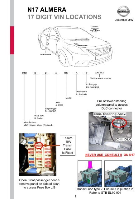
<strong>N<strong>17</strong></strong> <strong>ALMERA</strong><br />
<strong>17</strong> <strong>DIGIT</strong> <strong>VIN</strong> <strong>LOCATIONS</strong><br />
Open Front passenger door &<br />
remove panel on side of dash<br />
to access Fuse Box J/B<br />
Ensure<br />
10A<br />
Transit<br />
Fuse<br />
Is Fitted<br />
December 2012<br />
Pull off lower steering<br />
column panel to access<br />
DLC connector<br />
NEVER USE CONSULT II ON <strong>N<strong>17</strong></strong><br />
Transit Fuse type 2. Ensure it is pushed in.<br />
Refer to STB EL10-004<br />
1
PDI LOOSE PARTS<br />
2 keys tied together as per pictures below.<br />
• Wallet:<br />
o Owners Manual<br />
o Warranty and Maintenance guide<br />
o Dealer list and Misc. leaflets<br />
o Reverse Park Sensor Instruction Card (Ti only)<br />
• Spare tyre on steel rim for all models. Tyre matches those fitted to road wheels.<br />
• 4 x plastic wheel trims located in rear compartment (ST )<br />
• 4 x plastic centre caps for alloys wheels located in rear compartment (Ti)<br />
• Jack, tools & front tow hook located in spare wheel compartment.<br />
• Roof mounted aerial located in rear compartment.<br />
Ti<br />
Ignition Keys<br />
ST<br />
Cancellation of BCM Transit Mode.<br />
Ign. OFF / LH stalk DOWN / RH stalk DOWN<br />
Refer to STB EL10.004<br />
2<br />
Jack, tools & front tow hook<br />
Located in spare wheel compartment.<br />
Wheel Caps & Aerial Mast.<br />
(Ti Centre Caps not shown)
PDI LOOSE PARTS<br />
Tow Hook Cover (front only)<br />
Ensure the blanking cap in the front bumper for<br />
the Tow Hook is not missing.<br />
Ideally it should be placed in the Glove-box & only<br />
fitted when the vehicle is delivered to the<br />
customer.<br />
Aerial Mast<br />
Ensure the Aerial mast is not missing.<br />
Ideally it should be placed in the vehicle & only<br />
fitted when the vehicle is delivered to the<br />
customer.<br />
3
UNIQUE PRE–DELIVERY ACTIONS<br />
Clock Setting<br />
1. If the trip computer mode switch (*1) is pushed<br />
while the distance to empty or outside air<br />
temperature (if equipped) is displayed, the clock<br />
display will blink.<br />
2. Push & hold the clock settings switch (*1) for 3<br />
seconds. The hours display will start to flash.<br />
3. Push the clock settings switch (*1) to adjust the<br />
hour. To advance the time, hold down the switch<br />
(*1) & then release<br />
4. Wait at least 5 seconds for the minute display to<br />
flash.<br />
5. Push & hold the clock settings switch (*1) to<br />
adjust the minutes. To advance the time, hold<br />
down the switch (*1) & then release. Wait at least<br />
5 seconds for the second display “:” to flash.<br />
6. Push the clock settings switch (*1) to reset the<br />
second counter.<br />
Refer to Section 2 of the Owners Manual for more<br />
detail.<br />
Service Reminder Activation<br />
Ensure that the Service Reminder is set to remind<br />
the customer of the 1,000km service &/or the<br />
10,000km service.<br />
The service reminder function is set to OFF<br />
from the factory. This will need to be activated at<br />
Pre-Delivery.<br />
1. Switch Ignition ON.<br />
2. Press and hold switch (*1) for 3 seconds until<br />
the spanner symbol appears and then flashes at<br />
“0”.<br />
The service reminder function is now active.<br />
Service Reminder Setting<br />
1. Switch Ignition ON.<br />
2. Whilst the reminder is flashing, press switch (*1)<br />
to increment the setting to 1,000km for the first<br />
inspection and 10,000km after future services.<br />
NOTE: Wait for the reminder to stop flashing<br />
before switching the Ignition OFF, otherwise the<br />
setting won’t be saved.<br />
4<br />
(*1)<br />
Clock is located in LCD display below<br />
the odometer.
UNIQUE PRE–DELIVERY ACTIONS<br />
ST Ignition Keys<br />
Test the NATS operation of each key (start the<br />
engine).<br />
NOTE: Wait for the NATS security lamp to flash<br />
before testing each key.<br />
Remote Control Setting / Panic Alarm<br />
Keyless remote operation is separate to the NATS<br />
system. Therefore ensure the Keyless remote<br />
function works as well as being able to start the<br />
engine.<br />
Ti Ignition Keys (Intelligent Keys)<br />
Place the key in your pocket & from a lock<br />
vehicle condition, enter the vehicle & start the<br />
engine via the Intelligent Key process<br />
NOTE: Wait for the NATS security lamp to flash<br />
before testing each key.<br />
Also check that the key works via the Remote<br />
functionality (pressing the appropriate buttons<br />
should lock / unlock the doors)<br />
Remote Control / I-Key programming<br />
If the key starts the vehicle, the remote should<br />
also be working. Refer to the NATS Application<br />
chart and NATS OM in C-III to program<br />
additional keys.<br />
When I-KEY battery is flat<br />
If the battery in the I-KEY has failed, the only<br />
way the vehicle can be started is by holding the<br />
I-KEY unit against the Ignition button & pushing<br />
it.<br />
To open the doors mechanically, remove the<br />
mechanical key from the I-Key & insert it into the<br />
lock at the Exterior door handle.<br />
5
UNIQUE PRE–DELIVERY ACTIONS<br />
Engine Grounds - 1<br />
Ensure all engine ground connections are clean<br />
and tight.<br />
ECM / TCM Ground is located on the RHF strut<br />
tower in the engine bay.<br />
Engine Grounds - 2<br />
Ensure all engine ground connections are clean<br />
and tight.<br />
Engine Grounds - 3<br />
Ensure the Battery clamp connections are tight.<br />
Ensure the Ground from the Battery Neg > Body<br />
(LHF chassis rail) > Transmission housing is<br />
secure.<br />
NOTE: Battery MUST be tested and fully<br />
charged before delivery to Customer.<br />
Ensure ground cable link from Cylinder Head to<br />
Radiator support panel is secure.<br />
6
UNIQUE PRE–DELIVERY ACTIONS<br />
All DTC inspection;<br />
From the CONSULT III Plus Home screen, select<br />
DIAGNOSIS (All Systems).<br />
Ensure there are no DTC’s. There maybe cases<br />
where DTC’s are displayed, print them off as a<br />
record & then erase all the codes.<br />
Once again check for DTC’s after road test.<br />
CAN inspection;<br />
From the ALL DTC screen Select CAN Diag.<br />
CONSULT III PLUS OPERATIONS<br />
NOTE: The 18 character Model Code (SIS) must<br />
be typed into CONSULT III Plus – in capitals.<br />
This is found on the ID plate on the RH strut tower.<br />
Ensure the CAN is OK. All lines are to be GREEN.<br />
Steering Angle Sensor re-calibration after PDI<br />
Wheel Alignment;<br />
From the CONSULT III Plus Home screen, select<br />
MAINTENANCE.<br />
Select ST ANGLE SENSOR ADJUSTMENT.<br />
Follow the on screen prompts with the steering<br />
wheel in the exact straight ahead position.<br />
7
UNIQUE PRE–DELIVERY ACTIONS<br />
Reverse Parking Sensors (Ti only)<br />
Ensure the RP sensors functions as per the<br />
instruction card located in the Owners Manual<br />
wallet<br />
Instruction card should be located in the in the<br />
Glove Box with the Owners Manual<br />
Driver window Initialisation<br />
1. Switch ignition ON.<br />
2. Open window half way or more.<br />
3. Operate the power window switch to the UP<br />
direction and keep in this position for 3 seconds or<br />
longer once the window stops at the fully closed<br />
position.<br />
4. Test the AUTO window function to confirm correct<br />
operation.<br />
The drivers window on the ST variants does NOT have<br />
an ‘Auto-up / Anti pinch function. Therefore the<br />
above setting procedure is not possible.<br />
8
UNIQUE PRE–DELIVERY ACTIONS<br />
COOLING SYSTEM HOSE CLAMP PRE-CAUTION<br />
Always ensure that cooling system hose clamps have<br />
been properly secured as described in STB: LC10-001<br />
12V Battery Handling procedures<br />
Always ensure that the 12V Battery is properly maintained<br />
as outlined in STB: EL09-008<br />
Wheel Nut Tensions<br />
Ensure that the wheel nuts have been properly torqued as<br />
per the details in STB: MA12-001<br />
9
UNIQUE PRE–DELIVERY ACTIONS<br />
Audio System Repair / Exchange Process<br />
Clarion Audio – refer to Warranty Bulletin; AWB-<br />
011-07<br />
Contact TechLine for Bluetooth phone system<br />
related issues.<br />
Battery Saving Features<br />
Refer to STB EL10-004 for more details regarding<br />
the Battery Power Saving features.<br />
10