ms inverter - Adlee Powertronic Co., LTD
ms inverter - Adlee Powertronic Co., LTD
ms inverter - Adlee Powertronic Co., LTD

You also want an ePaper? Increase the reach of your titles
YUMPU automatically turns print PDFs into web optimized ePapers that Google loves.
R<br />
ADLEEPOWER<br />
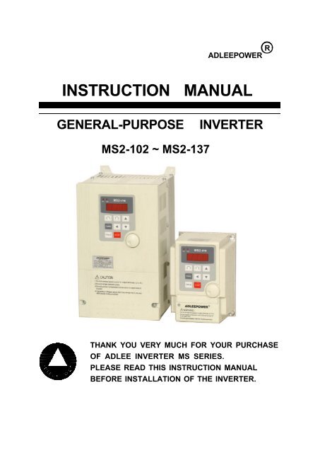
INSTRUCTION MANUAL<br />
GENERAL-PURPOSE INVERTER<br />
MS2-102 ~ MS2-137<br />
THANK YOU VERY MUCH FOR YOUR PURCHASE<br />
OF ADLEE INVERTER MS SERIES.<br />
PLEASE READ THIS INSTRUCTION MANUAL<br />
BEFORE INSTALLATION OF THE INVERTER.
CAUTION<br />
* Verify that the driver rated voltage coincides with the AC power<br />
supply voltage.<br />
Failure to observe this caution can result in personal injury or a fire.<br />
* Do not perform a withstand voltage test of the driver.<br />
It may cause semi-conductor elements to be damaged.<br />
* To connect a braking resistor, follow in APPENDIX A.<br />
Improper connection may cause the unit damaged or a fire.<br />
* Tighten terminal screws.<br />
Failure to observe this caution can result a fire.<br />
* Never connect the AC main circuit power supply to output terminals<br />
U, V and W.<br />
The <strong>inverter</strong> will be damaged and invalidate the guarantee.<br />
OPERATION<br />
WARNING<br />
* Only turn ON the input power supply after replacing the front cover.<br />
Do not remove the cover while current is flowing.<br />
Failure to observe this warning can result in an electrical shock.<br />
- III -
CAUTION<br />
* The control PC board employs CMOS ICs. Do not touch the CMOS<br />
elements by hand.<br />
They are easily damaged by static electricity.<br />
* Do not connect or disconnect wires or connectors while power is<br />
applied to the circuit.<br />
Failure to observe this caution can result in personal injury.<br />
OTHERS<br />
WARNING<br />
* Never modify the product.<br />
Failure to observe this warning can result in an electrical shock or<br />
personal injury and will invalidate the guarantee.<br />
- V -
1. RECEIVING<br />
2. SPECIFICATIONS<br />
3. DIMENSION DRAWINGS<br />
4. INSTALLATION<br />
CONTENTS<br />
5. DESCRIPTION OF TERMINALS<br />
6. DIGITAL OPERATION PANEL .<br />
7. FUNCTIONS DESCRIPTION<br />
8. DISPLAY ERROR CODES<br />
9. PRECAUTIONS<br />
10. TROUBLESHOOTING<br />
11. APPLICATION<br />
12. INVERTER SELECTION<br />
13. APPENDIX<br />
A. Optional braking resistor<br />
B. Terminal wiring diagram<br />
C. Remote operator<br />
1<br />
2<br />
3<br />
6<br />
7<br />
15<br />
16<br />
72<br />
76<br />
77<br />
78<br />
83<br />
85<br />
85<br />
86<br />
87
1. RECEIVING<br />
This MS series AC drive has gone through rigorous quality control tests<br />
at the factory before shipment. After receiving the AC drive, please check<br />
for the following :<br />
(1) No damage is found on each product after shipping.<br />
(2) The product is as ordered (check the nameplate, voltage and frequency).<br />
(3) A set of <strong>inverter</strong> unit and instruction manual is contained in the<br />
package.<br />
For any irregularity, contact the sales shop where you purchased<br />
immediately.<br />
(4) Description of name plate<br />
MODEL : MS 2 - 115<br />
MS series<br />
Voltage class :<br />
1 : 110V<br />
2 : 220V<br />
VER J 803<br />
1<br />
SOFTWARE<br />
HARDWARE<br />
VERSION<br />
Max Applicable motor(4 pole)<br />
Single Phase :<br />
102 : 0.2KW 104 : 0.4KW 107 : 0.75KW<br />
115 : 1.5KW 122 : 2.2KW 137 : 3.7KW
3. DIMENSION DRAWINGS<br />
Fig 1<br />
3<br />
Unit : mm
Fig 2<br />
4<br />
Unit : mm
Fig 3<br />
5<br />
Unit : mm
(2) <strong>Co</strong>ntrol circuit terminal<br />
MA CF3 MC A/B C VCC FA1 GNDFWDREV FT1 FT2 MT COM<br />
1 2 3 4 5 6 7 8 9 10 11 12 13 14<br />
Fault Relay<br />
<strong>Co</strong>ntact rating<br />
1A 240VAC<br />
1A 30VDC<br />
8<br />
FM
Running relay terminal<br />
No Symbol Terminal name Description<br />
1 MA Running signal A Running contact (normal open)<br />
2 CF3<br />
Running signal B / multifunction<br />
terminal<br />
9<br />
Running contact (normal close) / 5-8th<br />
speed terminal<br />
3 MC Running signal C Running contact (common)<br />
Alarm terminal<br />
No Symbol Terminal name Description<br />
4 A/B Alarm output B<br />
Fault alarm contact A(normal open) /<br />
B(normal close)<br />
5 C Alarm output C Fault alarm contact (common)<br />
Multi function analog terminal<br />
No Symbol Terminal name Description<br />
6 VCC Analog source Power source +10V of analog terminals<br />
7 FA1 Free analog terminal 1 See CD44 & 3-1 J7<br />
8 GND Analog common terminal <strong>Co</strong>mmon terminal of free analog terminals<br />
<strong>Co</strong>ntrol circuit terminal<br />
No Symbol Terminal name Description<br />
9 FWD Forward operation Forward operation / stop terminal<br />
10 REV Reverse operation Reverse operation / stop terminal<br />
11 FT1 Multi function terminal 1 See functions description (CD42)<br />
12 FT2 Multi function terminal 2 See functions description (CD43)<br />
13 MT<br />
Multi function output<br />
terminal<br />
Open collector output 50mA MAX<br />
RUN : Operating indicator<br />
MET : <strong>Co</strong>nnect to frequency meter, refer<br />
to CD07 description<br />
ARR : Frequency arrived indicator, refer to<br />
CD55 description<br />
14 COM <strong>Co</strong>mmon terminal <strong>Co</strong>mmon terminal of control terminals
(3) Description of Hardware setting<br />
MS1-104~107, MS2-102~122<br />
MS2-137<br />
S1<br />
RS485<br />
JP1<br />
RS485<br />
JP1<br />
S1<br />
J4 J5<br />
J3<br />
J10<br />
J7<br />
MA CF3 MC A/B C VCC FA1 GND FWD REV FT1 FT2 MT COM<br />
J10<br />
J4 J5<br />
MA CF3 MC A/B C VCC FA1 GND FWD REV FT1 FT2 MT COM<br />
10<br />
J3<br />
J7<br />
JP2<br />
JP2
(4) WIRING<br />
4-1 Wiring of main circuit<br />
12<br />
Filter<br />
L1<br />
L2<br />
E<br />
U<br />
V<br />
W<br />
THRY<br />
4-2 Wiring equipments<br />
Select the wiring equipment and wiring size, refer to the table<br />
below.<br />
1. On the input power side, a molded case circuit breaker (MCCB)<br />
to protect <strong>inverter</strong> primary wiring should be installed.<br />
2. A leakage current breaker threshold of 200mA and above, or of<br />
<strong>inverter</strong> use is recommended.<br />
3. Use of input side magnetic contactor. An input MC can be used to<br />
prevent an automatic restart after recovery from an external power<br />
loss during remote control operation. However, do not use the MC<br />
reduced reliability.<br />
4. In general, magnetic contactors on the output of the <strong>inverter</strong>,<br />
Should not be used for motor control. Starting a motor with the<br />
<strong>inverter</strong> running will cause large surge currents and the <strong>inverter</strong><br />
overcurrent protector to trigger.<br />
Model MS1 MS2<br />
Model No 104 107 102 104 107 115 122 137<br />
Capacity (KVA) 1.0 1.6 0.6 1.1 1.9 3.1 4.2 6.5<br />
Current (A) 2.5 4.1 1.4 2.5 4.1 7 10 16<br />
Circuit Breaker<br />
(MCCB) (A)<br />
Electro-Magnetic<br />
<strong>Co</strong>ntactor (A)<br />
Thermal relay<br />
RC value (A)<br />
15 15 6 10 10 15 20 20<br />
12 12 8 12 12 12 12 18<br />
4.8 7.6 1.2 2.4 3.8 6.8 9 15<br />
IM
6. DIGITAL OPERATION PANEL<br />
LED Operating<br />
Indication<br />
PROG<br />
FUNC<br />
STOP<br />
REV FWD MS2-IPM Model Indication<br />
FUNC<br />
PROG<br />
Operation key Key function Description<br />
FWD RUN Forward run <strong>Co</strong>mmands forward run<br />
REV RUN Reverse run <strong>Co</strong>mmands reverse run<br />
SHIFT<br />
Cursor<br />
movement<br />
Select the digit<br />
DOWN Down Decrease the parameter value<br />
UP Up Increase the parameter value<br />
PROG<br />
STOP<br />
Memory<br />
storage<br />
FUNC Function<br />
Digital Indication<br />
Digital Indication<br />
Saves the setting vaule<br />
Press once to select function CDxx and<br />
press again to change its content<br />
STOP Stop Stop operation / Escape to standby mode<br />
15<br />
F306<br />
FUNC<br />
CHARGE<br />
REV FWD<br />
REMOTE CONTROL<br />
STOP<br />
LED Operating Indication
ADJUST<br />
RANGE<br />
UNIT<br />
0.0 ~ 1200HZ 0.1HZ<br />
USER<br />
SETTING<br />
60HZ region<br />
50HZ region<br />
0 or 1 0 = lock 1 = Unlock<br />
0.1 ~ 6000.0Sec 0.1Sec<br />
0.1 ~ 6000.0Sec 0.1Sec<br />
0.0 ~ 1200HZ 0.1HZ<br />
0.5 ~ 30.0HZ 0.1HZ<br />
0 or 1 0 = Normal 1 = Jog<br />
30.0 ~ 1200HZ 0.1HZ<br />
60HZ region<br />
50HZ region<br />
17<br />
REMARK<br />
0 or 1 or 2 0 = CW/CCW 1 = CW 2 = CCW<br />
0 or 1 0 = Digital 1 = Analog<br />
0 or 1 0 = Dynamic brake 1 = Free running<br />
0 or 1<br />
0 ~ 2<br />
0.5 ~ 1200HZ 0.1HZ<br />
0.0 ~ 1200HZ 0.1HZ<br />
0.1 ~ 500.0 0.1<br />
25.0 ~ 1200HZ 0.1HZ<br />
60HZ region : Keypad<br />
50HZ region : Terminal<br />
0 = Normal 1 = F306<br />
2 = RS485 communication<br />
60HZ region<br />
50HZ region<br />
60HZ region<br />
50HZ region<br />
60HZ region<br />
50HZ region
DISPLAY<br />
CODE<br />
FUNCTION DEFAULT VALUE<br />
CD18 V/F pattern setting 0<br />
CD19 DC braking time 1.0Sec<br />
CD20 DC braking power 10<br />
CD21 Torque boost 0.0%<br />
CD22 Second speed setting 20.0HZ<br />
CD23 Third speed setting 30.0HZ<br />
CD24 Fourth speed setting 40.0HZ<br />
CD25 Acceleration time 2 10.0Sec<br />
CD26 Deceleration time 2 10.0Sec<br />
CD27 Carrier frequency 16.0K<br />
CD28 Output voltage gain 100.0%<br />
CD29 Frequency jump 1 0.0<br />
CD30 Frequency jump 2 0.0<br />
CD31 Freuqency jump 3 0.0<br />
CD32 Jump range 0.5HZ<br />
CD33 Frequency reference bias 0.0<br />
CD34 Frequency reference bias direction 0<br />
CD35 Frequency gain 100.0%<br />
CD36 The latest error record NONE<br />
CD37 Errors record 1 NONE<br />
18
ADJUST<br />
RANGE<br />
0 ~ 2<br />
UNIT<br />
0.0 ~ 25.0Sec 0.1Sec<br />
0 ~ 250 1<br />
0.0 ~ 25.0% 0.1%<br />
0.0 ~ 1200HZ 0.1HZ<br />
0.0 ~ 1200HZ 0.1HZ<br />
0.0 ~ 1200HZ 0.1HZ<br />
0.1 ~ 6000.0Sec 0.1Sec<br />
0.1 ~ 6000.0Sec 0.1Sec<br />
1.0K ~ 16.0K 0.1 K<br />
50.0 ~ 100.0% 0.1%<br />
0.0 ~ 1200HZ 0.1HZ<br />
0.0 ~ 1200HZ 0.1HZ<br />
0.0 ~ 1200HZ 0.1HZ<br />
0.5 ~ 3.0HZ 0.1HZ<br />
0.0 ~ 1200HZ 0.1HZ<br />
USER<br />
SETTING<br />
0 : <strong>Co</strong>nstant torque<br />
1 : (Frequency) 2.0<br />
2 : (Frequency) 3.0<br />
19<br />
REMARK<br />
0 or 1 0 = Positive 1 = Negative<br />
40.0 ~ 200.0% 1%
ADJUST<br />
RANGE<br />
UNIT<br />
0 ~ 15Hr hr.min<br />
0 ~ 15Hr hr.min<br />
0 ~ 15Hr hr.min<br />
0 ~ 15Hr hr.min<br />
0 or 1<br />
1 ~ 255<br />
0 ~ 3<br />
0 ~ 3<br />
0 ~ 7<br />
USER<br />
SETTING<br />
23<br />
REMARK
<strong>Co</strong>mmunication address description<br />
CODE FUNCTION DEFAULT VALUE<br />
100 Speed command for RS485 3<br />
101 Frequency data output for RS485<br />
102 Reserved<br />
103 Fault code for RS485<br />
24
ADJUST<br />
RANGE<br />
0 ~4<br />
UNIT<br />
0.1HZ<br />
USER<br />
SETTING<br />
25<br />
REMARK
7-1. Function setting<br />
Before starting test run, check carefully the following points :<br />
(1) Be sure to connect the power supply to L1, L2 (input terminals) and<br />
the motor to U.V.W. (output terminals). (Wrong connections will<br />
damage the <strong>inverter</strong>.)<br />
(2) Check that the input power supply coincide with input voltage and<br />
input phase of the <strong>inverter</strong>.<br />
(3) Check the signal lines for correct wiring.<br />
(4) Be sure to ground an earth terminal for personnel safety.<br />
(5) Check that other terminals other than earth terminal are not<br />
grounded.<br />
(6) Check that the <strong>inverter</strong> is mounted on the wall on non-flammable<br />
material.<br />
(7) For operation start and stop, use STOP and FWD / REV<br />
terminals. Never use input power supply to switch ON/OFF.<br />
26
Operating<br />
1-1. Pannel<br />
Action : (a) Press for forward / reverse operation.<br />
Speed : (a) Using to change motor speed with 1HZ<br />
increment step. or to select the digit for quick<br />
setting and confirm by<br />
Standby : (a) Press STOP back to standby mode after trip or function<br />
1-2. F306<br />
setting mode.<br />
Set CD13=1 and repower “ON”, operation same as 1-1 pannel.<br />
1-3. RS485 communication control<br />
Set CD13=2 and set CD74~CD78. (Refer to CD74~CD78).<br />
Using 06H function write command to address 100(64H).<br />
1 : CW, 2 : CCW, 3 : Stop, 4 : Clear fault.<br />
1-4. Terminal control<br />
Set CD12=1, writing refer to control circuit terminal wiring<br />
digaram.<br />
27<br />
PROG
First speed setting<br />
CD00<br />
Press key for increase or decrease the speed.<br />
Press key to select the digit for quick setting.<br />
Press to save the setting value.<br />
PROG<br />
Parameter lock<br />
CD01<br />
0 : Lock 1 : Unlock<br />
Function to prevent inadequate setting.<br />
To change the contents CD, set CD01=1 and press PROG first.<br />
To lock the data set CD01=0 and press PROG .<br />
Acceleration time 1<br />
CD02<br />
CD02 value corresponds to the<br />
time of acceleration from 0 to<br />
60HZ.(For 120Hz. setting, the<br />
arrival time to 120Hz is double.)<br />
Setting Range 0.0 ~ 1200HZ<br />
60HZ region 60.0HZ<br />
50HZ region 50.0HZ<br />
Setting Range 0 or 1<br />
Default value 0<br />
Setting Range 0.1 ~ 6000.0Sec<br />
Default value 10.0Sec<br />
28<br />
F<br />
60HZ<br />
0.1 6000 TIME(Sec)
Deceleration time 1<br />
CD03<br />
CD03 value corresponds to the<br />
time of deceleration from 50/60HZ<br />
to 0.<br />
Jogging frequency<br />
CD04<br />
Use terminal control refer to<br />
CD12 and CD42 setting,<br />
keyboard control refer to CD06.<br />
Start frequency<br />
CD05<br />
When setting this value, pay<br />
attention to the starting current.<br />
Setting Range 0.1 ~ 6000.0Sec<br />
Default value 10.0Sec<br />
F<br />
60HZ<br />
1200HZ<br />
0HZ<br />
Jog command<br />
Fset<br />
30HZ<br />
0.5HZ<br />
Run command<br />
0.1 6000 TIME(Sec)<br />
Setting Range 0.0 ~ 1200HZ<br />
Default value 5.0HZ<br />
29<br />
Time(Sec)<br />
Time(Sec)<br />
Setting Range 0.5 ~ 30.0HZ<br />
Default value 0.5HZ<br />
Time(Sec)<br />
Time(Sec)
Jog mode<br />
CD06<br />
0 : Normal 1 : Jog Mode<br />
1. Set jogging operation from key panel & .<br />
2. LED blinking in JOG mode.<br />
Note : Refer to CD12 & CD42 for using jog mode by terminal control.<br />
Frequency meter<br />
correspond<br />
CD07<br />
The specification of the output<br />
meter is 10V(i.e. 1mA) full scale<br />
rating.<br />
Set by CD07 the value will be<br />
correspond to maximum<br />
correspond of MET terminal<br />
output meter.<br />
CW or CCW or<br />
CW/CCW<br />
CD08<br />
Setting Range 0 or 1<br />
Default value 0<br />
Setting Range 30.0 ~ 1200HZ<br />
60HZ region 120.0HZ<br />
50HZ region 100.0HZ<br />
Output<br />
(meter)<br />
10V<br />
Changeable<br />
30.00 1200HZ(F)<br />
Setting Range 0 ~ 2<br />
Default value 0<br />
0 : CW/CCW operation<br />
1 : CW only<br />
2 : CCW only<br />
If inadequate operation, the “OPE2“ warning message will be<br />
indicated.<br />
30
Analog / Digital<br />
frequency input<br />
CD10<br />
0 : Operation frequency change by using or key and<br />
confirm by PROG .<br />
1 : Operation frequency depends on the analog of the knob.<br />
Note : Using key to change motor speed when<br />
CD01=1, the “OPE3“ warning message will be indicated.<br />
Dynamic brake /<br />
Free running<br />
CD11<br />
0 : Activates dynamic brake<br />
function when deceleration.<br />
1 : Output cut off when accept<br />
a stop command to be free<br />
running.<br />
Terminal / Keypad<br />
command<br />
CD12<br />
Setting Range 0 or 1<br />
Default value 1<br />
Setting Range 0 or 1<br />
Default value 0<br />
FWD RUN<br />
<strong>Co</strong>mmand<br />
CD11=0<br />
CD11=1<br />
time<br />
time<br />
time<br />
0 : RUN/STOP <strong>Co</strong>mmand from operation panel.<br />
1 : RUN/STOP <strong>Co</strong>mmand from control terminal.<br />
Note : If inadequate operation, the “OPE4“ warning message will be<br />
indicated.<br />
31<br />
F<br />
F<br />
Setting Range 0 or 1<br />
60HZ region 0<br />
50HZ region 1
Source operation<br />
command<br />
CD13<br />
Setting Range 0 ~ 2<br />
Default value 0<br />
0 : Normal<br />
1 : F306<br />
2 : RS485 communication<br />
Note : After finished this parameter setting, please repower “ON”.<br />
Maximum<br />
frequency limit<br />
CD14<br />
Minimum frequency<br />
limit<br />
CD15<br />
F<br />
1200HZ<br />
0.5HZ<br />
F<br />
1200HZ<br />
0.5HZ<br />
Setting Range 0.5 ~ 1200HZ<br />
60HZ region 120.0HZ<br />
50HZ region 50.0HZ<br />
32<br />
Max<br />
Speed command<br />
Setting Range 0.0 ~ 1200HZ<br />
Default value 0.0<br />
Max<br />
Speed command
Frequency display<br />
scale<br />
CD16<br />
Use the following equation to calculate the mechanical shaft speed in<br />
rpm.<br />
RPM = HZ × Scale setting<br />
When RPM > 9999 display for over range warning in this<br />
condition.<br />
Setting CD41=1 for display shown RPM.<br />
1st Maximum<br />
voltage frequency<br />
CD17<br />
Setting Range 0.1 ~ 500.0<br />
60HZ region 1.0<br />
50HZ region 30.0<br />
Pole Synchronous speed Scale<br />
setting<br />
50HZ 60HZ<br />
2 3000 3600 60<br />
4 1500 1800 30<br />
6 1000 1200 20<br />
8 750 900 15<br />
10 600 720 12<br />
12 500 600 10<br />
Setting Range 25.0 ~ 1200HZ<br />
60HZ region 60.0HZ<br />
50HZ region 50.0HZ<br />
Use 2nd V/F to set CD42(43)=7 and terminal FT1(2) close. 2nd V/F<br />
setting is at CD56.<br />
33
V<br />
<strong>Co</strong>nstant power<br />
0 = <strong>Co</strong>nstant torque curve<br />
1 = Reduce torque curve F 2.0<br />
2 = Reduce torque curve F 3.0<br />
F<br />
<strong>Co</strong>nstant torque<br />
V/F pattern setting<br />
CD18<br />
DC braking time<br />
CD19<br />
DC brake starting at<br />
frequency under 0.5HZ.<br />
Setting Range 0 ~ 2<br />
Default value 0<br />
Volt<br />
100%<br />
34<br />
V<br />
100%<br />
setting range<br />
25HZ 400HZ<br />
1200(Hz)<br />
Setting Range 0.0 ~ 25.0Sec<br />
Default value 1.0Sec<br />
F<br />
(HZ)<br />
DC<br />
0 25sec
DC braking power<br />
CD20<br />
CD20 setting DC voltage<br />
gain various braking<br />
power.<br />
Torque boost<br />
CD21<br />
DC<br />
F<br />
(HZ)<br />
35<br />
250<br />
DC Voltage<br />
0<br />
25sec<br />
Torque boosting is used to compensate the torque lost due to stator<br />
resistance. Over boosting will cause over current and high acoustic<br />
noise. V<br />
100%<br />
Second speed<br />
settting<br />
CD22<br />
Third speed setting<br />
CD23<br />
Setting Range 0 ~ 250<br />
Default value 10<br />
Setting Range 0.0 ~ 25.0%<br />
Default value 0.0%<br />
25%<br />
0%<br />
0.5(CD17) (CD17)<br />
Setting Range 0.0 ~ 1200HZ<br />
Default value 20.0HZ<br />
Setting Range 0.0 ~ 1200HZ<br />
Default value 30.0HZ
Fourth speed<br />
setting<br />
CD24<br />
Operation Signal<br />
Terminal CF1<br />
Terminal CF2<br />
Output frequency<br />
Acceleration time 2<br />
CD25<br />
ON<br />
ON ON<br />
ON<br />
Speed 1 Speed 1<br />
Speed 2Speed Speed 4<br />
3<br />
Setting Range 0.0 ~ 1200HZ<br />
Default value 40.0HZ<br />
36<br />
SPEED<br />
Terminal<br />
order<br />
CF1 CF2<br />
SPEED - 1 OFF OFF<br />
SPEED - 2 ON OFF<br />
SPEED - 3 OFF ON<br />
SPEED - 4 ON ON<br />
CD42 or CD43 setting FT1 or FT2=3, then CD25 or CD26 can be set.<br />
Deceleration time 2<br />
F<br />
(HZ)<br />
CD26<br />
Deceleration time 1<br />
2CH=OFF<br />
Acceleration<br />
time 2 Deceleration time 2<br />
2CH=ON 2CH=ON<br />
Acceleration<br />
time 1<br />
2CH=OFF<br />
Time(Sec)<br />
Setting Range 0.1 ~ 6000.0Sec<br />
Default value 10.0Sec<br />
Setting Range 0.1 ~ 6000.0Sec<br />
Default value 10.0Sec<br />
Description 2CH<br />
Acceleration time 1 OFF<br />
Deceleration time 1<br />
Acceleration time 2 ON<br />
Deceleration time 2<br />
To operate <strong>inverter</strong> with 2CH function, check to see CD42 or CD43=3.<br />
2CH command inputs from FT1 or FT2 terminal.
Carrier frequency<br />
CD27<br />
Increase the carrier frequency would reduce motor noise but efficiency<br />
might be decreased.<br />
Reduce the carrier frequency would increase noise and reduce motor<br />
current, and gain better efficiency.<br />
current current<br />
Low carrier frequency High carrier frequency<br />
Output voltage gain<br />
CD28<br />
Setting Range 1.0 ~ 16.0K<br />
Default value 16.0K<br />
Setting Range 50.0 ~ 100.0%<br />
Default value 100.0%<br />
Reduce output voltage for energy saving operation.<br />
Setting CD44=12 for FA1 terminal control.<br />
V<br />
100%<br />
Frequency jump 1<br />
CD29<br />
50%<br />
37<br />
(HZ)<br />
Setting Range 0.0 ~ 1200HZ<br />
Default value 0.0HZ
Frequency jump 2<br />
CD30<br />
Frequency jump 3<br />
CD31<br />
Jump range<br />
CD32<br />
Setting Range 0.0 ~ 1200HZ<br />
Default value 0.0HZ<br />
Setting Range 0.0 ~ 1200HZ<br />
Default value 0.0HZ<br />
F<br />
JUMP 1<br />
38<br />
JUMP 2<br />
JUMP 3<br />
Speed command<br />
Setting Range 0.5 ~ 3.0HZ<br />
Default value 0.5HZ<br />
V<br />
Speed command
Frequency<br />
reference bias<br />
CD33<br />
Move Frequency bias with<br />
same gradient.<br />
Frequency in the range of “-”<br />
bias, motor is stop.<br />
Freq. ref. bias<br />
direction<br />
CD34<br />
0 = Positive “+ “<br />
1 = Negative “-“<br />
Polarity setting for (CD33)<br />
frequency referance bias.<br />
Frequency gain<br />
CD35<br />
Setting Range 0.0 ~ 1200HZ<br />
Default value 0.0<br />
V<br />
100%<br />
+Bias<br />
-Bias 0<br />
Setting Range 0 or 1<br />
Default value 0<br />
V<br />
100%<br />
+Bias<br />
-Bias 0<br />
39<br />
+<br />
-<br />
+<br />
-<br />
Analog input<br />
Analog input<br />
Setting Range 40.0 ~ 200.0%<br />
Default value 100.0%<br />
FA1 analog input gain, refer to application example.
The latest error<br />
record<br />
CD36<br />
Error record 1<br />
CD37<br />
Error record 2<br />
CD38<br />
F<br />
(HZ)<br />
Error record 3<br />
CD39<br />
0 Vmax<br />
Analog input<br />
40<br />
200%<br />
100%<br />
40%<br />
Errors record flow-chart when Error occur. The new content will<br />
shift the other contents to one higher CD code and the highest one<br />
will be dropped.<br />
Error occur Loss<br />
CD36 CD37 CD38 CD39
Clear errors record<br />
CD40<br />
PROG<br />
Set CD40=1 and clear CD36 ~ CD39 Error record the contents in<br />
CD36 ~ CD39 are “ NONE “<br />
HZ/RPM Display<br />
CD41<br />
0 = HZ Display 1 = RPM Display<br />
Setting corrent scale CD16 for R.P.M display shown.<br />
FT1 Multi-Function<br />
Terminal 1<br />
CD42<br />
FT1<br />
FT2<br />
Setting Range 0 or 1<br />
Default value 0<br />
Setting Range 0 ~ 1<br />
Default value 0<br />
Setting Range 0 ~ 15<br />
Default value 0<br />
Symbol Function description<br />
0 -------- --------<br />
1 JOGF Jog operation FWD command<br />
2 JOGR Jog operation REV command<br />
3 2CH ACC/DEC time 2 command<br />
4 FRS Free running command<br />
5 3 - WIRE 3 - wire sequence mode<br />
6 CF3 5 - 8 Speed Setting Terminal<br />
7 VF2 2nd V/F curve setting (CD56)<br />
8 Reserved<br />
9 OH External over temperature command<br />
10~15 Reserved<br />
41
Note :<br />
1. Set jumper J4 and J5 to appropriate location before using FT1/FT2<br />
functions.<br />
2. To operate at 8 speeds function, all FT1/FT2/CF3 terminals set as<br />
FT1=CF1, FT2=CF2 and CF3=CF3.<br />
3 - WIRE CIRCUIT CONNECTION DIAGRAM (terminal latch function)<br />
CD42=5 FWD(REV) COMMAND<br />
CD12=1<br />
Application circuit<br />
7<br />
R<br />
FWD STOP<br />
R<br />
11 15<br />
R<br />
<strong>Co</strong>ntrol power<br />
FT2 Multi-Function<br />
Terminal 2<br />
CD43<br />
Refer to CD42 description.<br />
STOP COMMAND<br />
MS2 OUTPUT<br />
FWD(REV) COMMAND<br />
MS2 OUTPUT<br />
42<br />
with latch function<br />
7<br />
FWD STOP<br />
11 15<br />
R and CONTROL POWER not necessary<br />
Remark: STOP command entry from control<br />
terminal 11 FT1 or 12 FT2, and<br />
set CD42(FT1)=5 or CD43(FT2)=5<br />
before operation.<br />
Setting Range 0 ~ 15<br />
Default value 0
Free analog<br />
terminal 1<br />
CD44<br />
FA1 Function<br />
Setting Range 0 ~ 15<br />
Default value 0<br />
43<br />
Setting Range<br />
Min-------Max<br />
0 ---------- ----------<br />
1 Acceleration time 1 0 ~ CD02 <strong>Co</strong>ntent<br />
2 Deceleration time 1 0 ~ CD03 <strong>Co</strong>ntent<br />
3 Acceleration time 2 0 ~ CD25 <strong>Co</strong>ntent<br />
4 Deceleration time 2 0 ~ CD26 <strong>Co</strong>ntent<br />
5 Boost setting 0.0 ~ 25%<br />
6 DC Brake time 0 ~ 25Sec<br />
7 DC Brake Energy 0 ~ 250<br />
8 Speed 2 F-min ~ CD22 <strong>Co</strong>ntect<br />
9 Speed 3 F-min ~ CD23 <strong>Co</strong>ntect<br />
10 Speed 4 F-min ~ CD24 <strong>Co</strong>ntect<br />
11 Fmax F-min ~ CD14 content<br />
12 Output voltage gain 50% ~ 100%<br />
13 Speed 1 F-min ~ CD00 <strong>Co</strong>ntect<br />
14 Reserved<br />
15 Reserved
Version selector<br />
CD52<br />
Select function CD52, then use UP/Down key to select F50.0/F60.0<br />
Version. Press PROG to save it. System will return to the factory set-<br />
ting and go into standby mode.<br />
S curve<br />
CD53<br />
Setting S curve non-Linear Accel/Decel Operation from 1 to 10.<br />
Setting 0 is normal operation without S curve.<br />
FWD RUN COMMAND<br />
REV RUN COMMAND<br />
Output Frequency<br />
F<br />
(Hz)<br />
Setting Range F50.0 / F60.0<br />
60HZ region F60.0<br />
50HZ region F50.0<br />
Setting Range 0 ~ 10<br />
Default value 0<br />
CD53=0<br />
CD53=3<br />
CD53=7<br />
ACCEL DECEL<br />
S Curve period<br />
45<br />
TIME<br />
DC injection<br />
Braking Time
2nd Maximum<br />
Voltage frequency<br />
CD56<br />
Set CD42(CD43)=7 define FT1(FT2) terminal for hardware V/F curve<br />
switcher.<br />
Open : select the 1st V/F curve preset in CD17<br />
Close : select the 2nd V/F curve preset in CD56<br />
V<br />
100%<br />
CD17 CD56 (f)<br />
(1st) (2nd)<br />
Auto running mode<br />
CD58<br />
Setting Range 25.0 ~ 1200HZ<br />
Default value 60.0HZ<br />
47<br />
1 V/F<br />
FT1 COM<br />
2 V/F<br />
Setting Range 0 ~ 6<br />
Default value 0<br />
System can operate at digital panel control only when set at auto-running<br />
mode. CD10=1 and CD12=1 are inactive.<br />
SPEED 1 st 2 nd 3 rd 4 th Master /<br />
suspend<br />
VALUE<br />
RANGE UNIT<br />
SPEED SETTING CD47 CD48 CD49 CD50 CD00 0 ~ 1200 Hz<br />
TIMER SETTING CD59 CD60 CD61 CD62 CD63 0 ~ 15.00 hr.min
CD58 Auto running mode<br />
START<br />
0 Speed with timing control disable<br />
1 Sequence running then constant speed running<br />
2 Sequence running then stop and repeat from 1st step for cycling<br />
3<br />
Sequence running then stop and repeat from 1st step in reversed<br />
direction for cycling<br />
4 Sequence running, and repeat for cycling<br />
5 Sequence running then perform reverse direction and repeat for cycling<br />
6 Sequence running then stop<br />
1st SPEED 3rd 2 SPEED<br />
nd SPEED 4th SPEED<br />
48<br />
Master speed<br />
/ suspend<br />
1st step 2nd step 4th step 5th 3 step<br />
rd step<br />
CD58=1<br />
CD58=1<br />
(S)<br />
CD58=2<br />
(S)<br />
CD47<br />
CD48<br />
CD49<br />
CD50<br />
CD00<br />
CD59 CD60 CD61 CD62 (T)<br />
CD47<br />
CD48<br />
CD49<br />
CD50<br />
CD00<br />
CD47<br />
CD48<br />
CD49<br />
CD50<br />
CD00<br />
CD59 CD60 CD61 CD62CD63 CD59 CD60 CD61 CD62 CD63 CD59 (T)
CD58=3<br />
(S)<br />
CD58=4<br />
(S)<br />
CD58=5<br />
(S)<br />
CD58=6<br />
(S)<br />
CD47<br />
CD48<br />
CD49<br />
CD50<br />
CD59 CD60<br />
CD00<br />
CD61 CD62 CD63 CD59 CD60 CD61 CD62 CD63 CD59<br />
CD47<br />
CD47<br />
CD59<br />
CD48<br />
CD48<br />
CD49<br />
CD50<br />
CD60 CD61 CD62<br />
CD00<br />
CD63<br />
CD47<br />
CD48<br />
CD49<br />
CD50<br />
CD59 CD60 CD61 CD62 CD63 CD59 CD60 CD61 CD62 CD63 CD59 (T)<br />
CD47<br />
CD49<br />
CD48<br />
CD50<br />
CD00<br />
CD49<br />
CD47<br />
CD59 CD60 CD61 CD62<br />
CD47<br />
CD50<br />
CD48<br />
CD48<br />
CD49<br />
CD00<br />
CD59 CD60 CD61 CD62 CD63<br />
CD49<br />
49<br />
CD50<br />
CD50<br />
CD00<br />
CD63<br />
CD00<br />
CD59<br />
(T)<br />
One time sequence running then stop.<br />
(T)<br />
(T)
1st step timer<br />
CD59<br />
Setting running time for 1th speed.(CD47)<br />
2st step timer<br />
CD60<br />
Setting running time for 2th speed.(CD48)<br />
3st step timer<br />
CD61<br />
Setting running time for 3th speed.(CD49)<br />
4st step timer<br />
CD62<br />
Setting running time for 4th speed.(CD50)<br />
5st step timer<br />
CD63<br />
Setting running time for 1th speed.(CD00)<br />
Setting Range 0 ~ 15 Hr<br />
Default value 0.01 Hr.min<br />
Setting Range 0 ~ 15Hr<br />
Default value 0.00Hr.min<br />
Setting Range 0 ~ 15Hr<br />
Default value 0.00Hr.min<br />
Setting Range 0 ~ 15Hr<br />
Default value 0.00Hr.min<br />
Setting Range 0 ~ 15Hr<br />
Default value 0.00Hr.min<br />
50
Transmission fault<br />
treatment<br />
CD76<br />
0 : Alarm and keep operation.<br />
1 : Alarm and decelerate to stop.<br />
2 : Alarm and free to stop.<br />
3 : No alarm and keep operation.<br />
<strong>Co</strong>mmunicator<br />
protocol<br />
CD78<br />
Setting Range 0 ~ 3<br />
Default Value 0<br />
Setting Range 0 ~ 7<br />
Default Value 0<br />
A. Date format<br />
0 : 8,N,1 RTU (1 start bit+8 data bits+1 stop bit)<br />
8,N,1 RTU (10-bit)(character frame in hexadecimal)<br />
Start<br />
bit<br />
1 : 8,N,2 RTU (1 start bit+8 data bits+2 stop bit)<br />
8,N,2 RTU (11-bit)(character frame in hexadecimal)<br />
Start<br />
bit<br />
0 1 2 3 4 5 6 7<br />
2 : 8,E,1 RTU (1 start bit+8data bits+1 Even bit+1 stop bit)<br />
8,E,1 RTU (11-bit)(character frame in hexadecimal)<br />
Start<br />
bit<br />
0 1 2 3 4 5 6 7<br />
52<br />
Stop<br />
bit<br />
Stop<br />
bit<br />
0 1 2 3 4 5 6 7 Even<br />
Parity<br />
Stop<br />
bit<br />
Stop<br />
bit
3 : 8,O,1 RTU (1 start bit+8data bits+1 Odd bit+1 stop bit)<br />
8,O,1 RTU (11-bit)(character frame in hexadecimal)<br />
Start<br />
bit<br />
4 : 8,N,1 ASCII (1 start bit+8data bits+1 stop bit)<br />
8,N,1 ASCII (10-bit)(character frame in hexadecimal)<br />
Start<br />
bit<br />
5 : 8,N,2 ASCII (1 start bit+8data bits+2 stop bit)<br />
8,N,2 ASCII (11-bit)(character frame in hexadecimal)<br />
Start<br />
bit<br />
0 1 2 3 4 5 6 7 Odd<br />
Parity<br />
6 : 8,E,1 ASCII (1 start bit+8data bits+1 Eveb bit+1 stop bit)<br />
8,E,1 ASCII (11-bit)(character frame in hexadecimal)<br />
Start<br />
bit<br />
0 1 2 3 4 5 6 7<br />
Stop<br />
bit<br />
7 : 8,O,1 ASCII (1 start bit+8data bits+1 Odd bit+1 stop bit)<br />
8,O,1 ASCII (11-bit)(character frame in hexadecimal)<br />
Start<br />
bit<br />
0 1 2 3 4 5 6 7<br />
0 1 2 3 4 5 6 7<br />
0 1 2 3 4 5 6 7<br />
Stop<br />
bit<br />
Even<br />
Parity<br />
Odd<br />
Parity<br />
53<br />
Stop<br />
bit<br />
Stop<br />
bit<br />
Stop<br />
bit<br />
Stop<br />
bit
C. ASCII code description<br />
Character "0" "1" "2" "3" "4" "5" "6" "7"<br />
ASCII code 30H 31H 32H 33H 34H 35H 36H 37H<br />
Character "8" "9" "A" "B" "C" "D" "E" "F"<br />
ASCII code 38H 39H 41H 42H 43H 44H 45H 46H<br />
D. Function code<br />
1. 03H : Read AC drive’s setting<br />
2. 06H : Write parameter setting into AC drive<br />
3. 08H : <strong>Co</strong>mmunication loop detection<br />
(1) 03H : Read AC drive's setting<br />
<strong>Co</strong>mputer command message<br />
D1 : <strong>Co</strong>mmunication address<br />
D2 : Function code<br />
D3 : Parameter number (H)<br />
D4 : Parameter number (L)<br />
D5 : Quantity of parameter (H) (word count)<br />
D6 : Quantity of parameter (L) (word count)<br />
D7 : CRCL<br />
D8 : CRCH<br />
AC drive response message<br />
D1 : <strong>Co</strong>mmunication address<br />
D2 : Function code<br />
D3 : Quantity of parameter (byte count)<br />
D4 : <strong>Co</strong>ntent of data (H)<br />
D5 : <strong>Co</strong>ntent of data (L)<br />
...<br />
Dn-1 : CRCL<br />
Dn : CRCH<br />
55<br />
(00~FFh)<br />
(03h)<br />
(00h)<br />
(0~67h)<br />
(00h)<br />
(00~10h)<br />
(0~FFh)<br />
(0~FFh)<br />
(01~FFh)<br />
(03h)<br />
(00~20h)<br />
(0~FFh)<br />
(0~FFh)<br />
(0~FFh)<br />
(0~FFh)
Example : Read two parameters of AC drive address 52(34H) from<br />
CD22. CD22=20.00(07D0H) CD23=30.00(0BB8H).<br />
1. RTU<br />
2. ASCII<br />
<strong>Co</strong>mputer command message AC drive response message<br />
D1 Address 34H D1 Address 34H<br />
D2 Function 03H D2 Function 03H<br />
D3 Start address (H) 00H D3<br />
56<br />
Quantity of data<br />
(count by byte)<br />
04H<br />
D4 Start address (L) 16H D4 CD22 content (H) 07H<br />
D5 # of data (H) 00H D5 CD22 content (L) D0H<br />
D6 # of data (L) 02H D6 CD23 content (H) 0BH<br />
D7 CRCL CRCL D7 CD23 content (L) B8H<br />
D8 CRCH CRCH D8 CRCL CRCL<br />
D1<br />
D2<br />
D3<br />
D4<br />
D5<br />
D9 CRCH CRCH<br />
<strong>Co</strong>mputer command message AC drive response message<br />
STX 3A STX 3A<br />
Address '3'<br />
Address '4'<br />
Function '0'<br />
Function '3'<br />
Start address '0'<br />
Start address '0'<br />
Start address '1'<br />
Start address '6'<br />
# of data '0'<br />
# of data '0'<br />
33 Address '3'<br />
33<br />
D1<br />
34 Address '4'<br />
34<br />
30 Function '0'<br />
30<br />
D2<br />
33 Function '3'<br />
33<br />
30 # of data '0'<br />
30<br />
D3<br />
30 count by byte '4' 34<br />
31 CD22 content '0' 30<br />
D4<br />
36 CD22 content '7' 37<br />
30 CD22 content 'D' 44<br />
D5<br />
30 CD22 content '0' 30
<strong>Co</strong>mputer write CD00 content (60.00HZ) to <strong>inverter</strong> address=52<br />
1. RTU<br />
<strong>Co</strong>mputer command message<br />
D1<br />
34H<br />
AC drive response message<br />
D1<br />
34H<br />
2. ASCII<br />
D1<br />
D2<br />
D3<br />
D4<br />
D5<br />
D6<br />
D2<br />
06H<br />
D2<br />
06H<br />
D3<br />
00H<br />
D3<br />
00H<br />
D4<br />
00H<br />
D4<br />
00H<br />
D5<br />
17H<br />
D5<br />
17H<br />
D6<br />
70H<br />
D6<br />
70H<br />
59<br />
D7<br />
CRCL<br />
D7<br />
CRCL<br />
D8<br />
CRCH<br />
D8<br />
CRCH<br />
<strong>Co</strong>mputer command message AC drive response message<br />
STX 3A STX 3A<br />
Address '3'<br />
Address '4'<br />
Function '0'<br />
Function '6'<br />
Number of parameter '0'<br />
Number of parameter '0'<br />
Number of parameter '0'<br />
Number of parameter '0'<br />
CD00 content '1'<br />
CD00 content '7'<br />
CD00 content '7'<br />
CD00 content '0'<br />
33 Address '3'<br />
33<br />
D1<br />
34 Address '4'<br />
34<br />
30 Function '0'<br />
30<br />
D2<br />
36 Function '6'<br />
36<br />
30 Number of parameter '0' 30<br />
D3<br />
30 Number of parameter '0' 30<br />
30 Number of parameter '0' 30<br />
D4<br />
30 Number of parameter '0' 30<br />
31 CD00 content '1'<br />
31<br />
D5<br />
37 CD00 content '7'<br />
37<br />
37 CD00 content '7'<br />
37<br />
D6<br />
30 CD00 content '0'<br />
30<br />
D7 LRC HI LRC HI D7 LRC HI LRC HI<br />
D8 LRC LO LRC LO D8 LRC LO LRC LO<br />
END HI 0D END HI 0D<br />
END LO 0A END LO 0A
<strong>Co</strong>mputer command message <strong>inverter</strong> address=52 foward run at 60.00HZ<br />
1. RTU<br />
Step 1. Write CD00=60.00HZ (6000=1770H) to AC drive address=52<br />
<strong>Co</strong>mputer command message<br />
D1<br />
34H<br />
D2<br />
06H<br />
D3<br />
00H<br />
D4<br />
00H<br />
AC drive response message<br />
D1<br />
34H<br />
D2<br />
06H<br />
D3<br />
00H<br />
D4<br />
00H<br />
Step 2. Write address 100 (64H)=1<br />
<strong>Co</strong>mputer command message<br />
D1<br />
34H<br />
AC drive response message<br />
D1<br />
34H<br />
D2<br />
06H<br />
D2<br />
06H<br />
D3<br />
00H<br />
D3<br />
00H<br />
D4<br />
64H<br />
D4<br />
64H<br />
D5<br />
17H<br />
D5<br />
17H<br />
D5<br />
00H<br />
D5<br />
00H<br />
D6<br />
70H<br />
D6<br />
70H<br />
D6<br />
01H<br />
D6<br />
01H<br />
Note : When address 100=1, speed is depended on terminal setting<br />
(CF1, CF2, CF3)<br />
2. ASCII<br />
Step 1. Write CD00(60.00HZ) to <strong>inverter</strong> address=52<br />
D1<br />
D2<br />
60<br />
D7<br />
CRCL<br />
D7<br />
CRCL<br />
D7<br />
CRCL<br />
D7<br />
CRCL<br />
D8<br />
CRCH<br />
D8<br />
CRCH<br />
D8<br />
CRCH<br />
D8<br />
CRCH<br />
<strong>Co</strong>mputer command message AC drive response message<br />
STX 3A STX 3A<br />
Address '3'<br />
Address '4'<br />
Function '0'<br />
Function '6'<br />
33 Address '3'<br />
33<br />
D1<br />
34 Address '4'<br />
34<br />
30 Function '0'<br />
30<br />
D2<br />
36 Function '6'<br />
36
D3<br />
D4<br />
D5<br />
D6<br />
<strong>Co</strong>mputer command message AC drive response message<br />
Number of parameter '0'<br />
Number of parameter '0'<br />
Number of parameter '0'<br />
Number of parameter '0'<br />
CD79 content '1'<br />
CD79 content '7'<br />
CD79 content '7'<br />
CD79 content '0'<br />
30 Number of parameter '0' 30<br />
D3<br />
30 Number of parameter '0' 30<br />
30 Number of parameter '0' 30<br />
D4<br />
30 Number of parameter '0' 30<br />
31 CD79 content '1'<br />
31<br />
D5<br />
37 CD79 content '7'<br />
37<br />
37 CD79 content '7'<br />
37<br />
D6<br />
30 CD79 content '0'<br />
30<br />
D7 LRC HI LRC HI D7 LRC HI LRC HI<br />
D8 LRC LO LRC LO D8 LRC LO LRC LO<br />
END HI 0D END HI 0D<br />
END LO 0A END LO 0A<br />
Step 2. Write address 100 (64H)=1<br />
D1<br />
D2<br />
D3<br />
D4<br />
D5<br />
<strong>Co</strong>mputer command message AC drive response message<br />
STX 3A STX 3A<br />
Address '3'<br />
Address '4'<br />
Function '0'<br />
Function '6'<br />
<strong>Co</strong>ntent of data '0'<br />
<strong>Co</strong>ntent of data '0'<br />
<strong>Co</strong>ntent of data '6'<br />
<strong>Co</strong>ntent of data '4'<br />
CD31 content '0'<br />
CD31 content '0'<br />
33 Address '3'<br />
33<br />
D1<br />
34 Address '4'<br />
34<br />
30 Function '0'<br />
30<br />
D2<br />
36 Function '6'<br />
36<br />
30 <strong>Co</strong>ntent of data '0'<br />
30<br />
D3<br />
30 <strong>Co</strong>ntent of data '0'<br />
30<br />
36 <strong>Co</strong>ntent of data '6'<br />
36<br />
D4<br />
34 <strong>Co</strong>ntent of data '4'<br />
34<br />
30 CD31 content '0'<br />
30<br />
D5<br />
30 CD31 content '0'<br />
30<br />
61
D6<br />
<strong>Co</strong>mputer command message AC drive response message<br />
CD31 content '0'<br />
CD31 content '1'<br />
30 CD31 content '0'<br />
30<br />
D6<br />
31 CD31 content '1'<br />
31<br />
D7 LRC HI LRC HI D7 LRC HI LRC HI<br />
D8 LRC LO LRC LO D8 LRC LO LRC LO<br />
END HI 0D END HI 0D<br />
END LO 0A END LO 0A<br />
(3) 08H : <strong>Co</strong>mmunication loop detection<br />
<strong>Co</strong>mputer command message<br />
D1 : <strong>Co</strong>mmunication address<br />
D2 : Function code<br />
D3 : Data 1<br />
D4 : Data 2<br />
D5 : Data 3<br />
D6 : Data 4<br />
D7 : CRCL<br />
D8 : CRCH<br />
AC drive response message<br />
D1 : <strong>Co</strong>mmunication address<br />
D2 : Function code<br />
D3 : Data 1<br />
D4 : Data 2<br />
D5 : Data 3<br />
D6 : Data 4<br />
D7 : CRCL<br />
D8 : CRCH<br />
62<br />
(0~FFh)<br />
(08h)<br />
(0~FFh)<br />
(0~FFh)<br />
(0~FFh)<br />
(0~FFh)<br />
(0~FFh)<br />
(0~FFh)<br />
(0~FFh)<br />
(08h)<br />
(0~FFh)<br />
(0~FFh)<br />
(0~FFh)<br />
(0~FFh)<br />
(0~FFh)<br />
(0~FFh)<br />
AC drive response messages need to be same as command message when<br />
do communication loop detection.
Ex. Write data data 1=11, data 2=22, data 3=33 and data 4=44 to AC<br />
drive address 52(34H)<br />
1. RTU<br />
2. ASCII<br />
<strong>Co</strong>mputer command message AC drive response message<br />
D1 Address 34H D1 Address 34H<br />
D2 Function 08H D2 Function 08H<br />
D3 Data 1 11H D3 Data 1 11H<br />
D4 Data 2 22H D4 Data 2 22H<br />
D5 Data 3 33H D5 Data 3 33H<br />
D6 Data 4 44H D6 Data 4 44H<br />
D7 CRCL CRCL D7 CRCL CRCL<br />
D8 CRCH CRCH D8 CRCH CRCH<br />
D1<br />
D2<br />
D3<br />
D4<br />
D5<br />
D6<br />
<strong>Co</strong>mputer command message AC drive response message<br />
STX 3A STX 3A<br />
Address '3'<br />
Address '4'<br />
Function '0'<br />
Function '8'<br />
<strong>Co</strong>ntent1 '1'<br />
<strong>Co</strong>ntent1 '1'<br />
<strong>Co</strong>ntent2 '2'<br />
<strong>Co</strong>ntent2 '2'<br />
<strong>Co</strong>ntent3 '3'<br />
<strong>Co</strong>ntent3 '3'<br />
<strong>Co</strong>ntent4 '4'<br />
<strong>Co</strong>ntent4 '4'<br />
33 Address '3'<br />
33<br />
D1<br />
34 Address '4'<br />
34<br />
30 Function '0'<br />
30<br />
D2<br />
38 Function '8'<br />
38<br />
31 <strong>Co</strong>ntent1 '1'<br />
31<br />
D3<br />
31 <strong>Co</strong>ntent1 '1'<br />
31<br />
32 <strong>Co</strong>ntent2 '2'<br />
32<br />
D4<br />
32 <strong>Co</strong>ntent2 '2'<br />
32<br />
33 <strong>Co</strong>ntent3 '3'<br />
33<br />
D5<br />
33 <strong>Co</strong>ntent3 '3'<br />
33<br />
34 <strong>Co</strong>ntent4 '4'<br />
34<br />
D6<br />
34 <strong>Co</strong>ntent4 '4'<br />
34<br />
63
<strong>Co</strong>mputer command message AC drive response message<br />
D7 LRC HI LRC HI D7 LRC HI LRC HI<br />
D8 LRC LO LRC LO D8 LRC LO LRC LO<br />
END HI 0D END HI 0D<br />
END LO 0A END LO 0A<br />
CRC(Cyclical Redundancy Check) is calculated by the following steps:<br />
Step 1. Load a 16-bit register (called CRC register) with FFFFH.<br />
Step 2. Exclusive OR the first 8-bit byte of the command message with<br />
the low order byte of the 16-bit CRC register, putting the result<br />
in the CRC register.<br />
Step 3. Shift the CRC registers one bit to the right with MSB zero filling.<br />
Extract and examine the LSB.<br />
Step 4. If the LSB of CRC register is 0, repeat step 3, else Exclusive OR<br />
the CRC register with the polynomial value A001H.<br />
Step 5. Repeat step 3 and 4 until eight shifts have been performed. When<br />
this is done, a complete 8-bit byte will have been processed.<br />
Step 6. Repeat steps 2 to 5 for the next 8-bit byte of the command message.<br />
<strong>Co</strong>ntinue doing this until all bytes have been processed.<br />
The final contents of the CRC register are the CRC value.<br />
LRC (Longitudinal Redundancy Check) is calculated by summing up,<br />
module 256, the values of the bytes from Address to last data character<br />
then calculating the hexadecimal representation of the 2’s-complement<br />
negation of the sum.<br />
For example, refer to 06H at CD00=60.00HZ<br />
34+06+00+00+17+70=C1H<br />
the 2’s-complement negation of C1H is 3FH<br />
64
E. <strong>Co</strong>mmunication error respond<br />
Once communication error happened, <strong>inverter</strong> will respond “Function<br />
code and 80H” and communication error code to master system.<br />
<strong>Co</strong>mmunication error code definition<br />
Error code Description<br />
01H Function code error, only 03/06/08 available<br />
02H Illegal data value (data value outside limit value)<br />
03H Illegal data address (data address is not available)<br />
04H Illegal operation command<br />
05H Check sum error<br />
06H Drive busy (Inteval time between two data structures are too short)<br />
07H Drive fault, check AC drive<br />
0BH Data structure too short<br />
0CH Data structure too long<br />
0DH No start code or end code in ASCII communication<br />
1. RTU<br />
Once communication error happend, AC drive respond as follow.<br />
D1<br />
Address<br />
D2<br />
Function code & 80H<br />
D3<br />
Error code<br />
65<br />
D4<br />
CRCL<br />
D5<br />
CRCH
2. ASCII<br />
Start code 3A<br />
Address (01)<br />
Function code & 80H (86)<br />
Error code (02)<br />
LRC (77)<br />
Ex. Write CD00=1500HZ(3A98H), but maximum value of CD00 is<br />
1200HZ.<br />
1. RTU<br />
<strong>Co</strong>mputer command message<br />
AC drive response message<br />
30<br />
31<br />
38<br />
36<br />
30<br />
32<br />
37<br />
37<br />
End code H 0D<br />
End code L 0A<br />
D1<br />
01H<br />
D1<br />
01H<br />
D2<br />
06H<br />
D2<br />
86H<br />
D3<br />
00H<br />
D3<br />
02H<br />
D4<br />
00H<br />
D5<br />
3AH<br />
D4<br />
CRCL(C3H)<br />
D6<br />
98H<br />
66<br />
D7<br />
CRCL<br />
D8<br />
CRCH<br />
D5<br />
CRCH(A1H)
2. ASCII<br />
D1<br />
D2<br />
D3<br />
D4<br />
D5<br />
D6<br />
<strong>Co</strong>mputer command message AC drive response message<br />
STX 3A STX 3A<br />
Address '0'<br />
Address '1'<br />
Function '0'<br />
Function '6'<br />
Address content '0'<br />
Address content '0'<br />
Address content '0'<br />
Address content '0'<br />
CD00 content '3'<br />
CD00 content 'A'<br />
CD00 content '9'<br />
CD00 content '8'<br />
30 Address '0'<br />
30<br />
D1<br />
31 Address '1'<br />
31<br />
30 Function '8'<br />
38<br />
D2<br />
36 Function '6'<br />
36<br />
30 Error code '0'<br />
30<br />
D3<br />
30 Error code '2'<br />
32<br />
30 LRC HI '7'<br />
37<br />
D4<br />
30 LRC LO '7'<br />
37<br />
33 END HI 0D<br />
41 END LO 0A<br />
39<br />
38<br />
D7 LRC HI LRC HI<br />
D8 LRC LO LRC LO<br />
END HI 0D<br />
END LO 0A<br />
67
<strong>Co</strong>mmunication address description<br />
Speed command of<br />
RS485<br />
100<br />
Setting Range 0 ~ 4<br />
Default Value 3<br />
0 : Normal<br />
1 : Forward run<br />
2 : Reverse run<br />
3 : Stop<br />
4 : Fail mode reset<br />
Note : 1.Fail mode reset by writting address 100 content=4. It will fall<br />
into EEP1 error mode if any operation command is set before<br />
reset the fail mode. It needs to re-power ON to remove this error.<br />
2. Speed command is CD00, or using CF1/CF2/CF3 terminal to<br />
select 2 nd ~8 th speed (CD22~CD24, CD47~CD50).<br />
Frequency data<br />
output for RS485<br />
101<br />
Unit 0.1HZ<br />
To know output frequency, using function 03H to read address 101<br />
content.<br />
68
Fault code for<br />
RS485<br />
103<br />
Using 03H function to read address 103(67H) content to know the cause<br />
of fault if fault occurred.<br />
01H : EP0<br />
02H : PF01<br />
03H : PF02<br />
04H : PF03<br />
05H : PF04<br />
07H : OH<br />
08H : OL<br />
09H : EEP1<br />
0AH : EEP2<br />
31H : OPE1<br />
32H : OPE2<br />
34H : OPE4<br />
35H : OPE5<br />
36H : OPE6<br />
37H : OPE7<br />
38H : OPE8<br />
39H : OPE9<br />
69
7-2. Operation key-in sequence<br />
Setting<br />
sequence<br />
FUNC<br />
FUNC<br />
PROG<br />
FUNC<br />
FUNC<br />
PROG<br />
EXAMPLE : CHANGE acceleration time<br />
Display<br />
indicator<br />
70<br />
Description<br />
In waiting mode, the display is blinking<br />
Enter function mode<br />
Select function number 1 (parameter lock)<br />
Press "FUNC" again to change the parameter value<br />
Enable to change parameter<br />
Press "PROG" to save the parameter and back to<br />
standby mode<br />
Enter function mode<br />
Select function number 2 (acceleration time)<br />
Press "FUNC" again to change the parameter value<br />
Select the first digit<br />
Increase the value to 3<br />
Select the second digit<br />
Increase the value to 2<br />
Press "PROG" to save CD02=12.3 and back to<br />
standby mode.
Setting<br />
sequence<br />
FUNC<br />
FUNC<br />
PROG<br />
CHANGE maximum frequency limit<br />
Display<br />
indicator<br />
Enter function mode<br />
Increase the value to 4<br />
Select the second digit<br />
Increase the value to 1<br />
71<br />
Description<br />
Press "FUNC" again to change the Maximum<br />
frequency limit<br />
Select the second digit<br />
Decrease the value to 90HZ<br />
Press "PROG" to save CD14=90HZ and back to<br />
standby mode
8. DISPLAY ERROR CODES<br />
A. Inverter self-checking errors<br />
Internal protection<br />
CPU<br />
Noise protection.<br />
Self test failure protection<br />
Program check sum error<br />
EP0<br />
EEPROM access error<br />
EEP1<br />
EEPROM check-sum error<br />
EEP2<br />
Power device failure 1<br />
PF01<br />
Power device failure during acceleration<br />
Power device failure 2<br />
PF02<br />
Power device failure during constant frequency<br />
72
Power device failure 3<br />
PF03<br />
Power device failure during deceleration (stopping)<br />
Power device failure 4<br />
PF04<br />
Power device failure during stand-by<br />
B. Operation errors<br />
Parameter Locked<br />
OPE1<br />
To change the contents of CD02~CD52 set CD01=press PROG first<br />
FWD or REV only<br />
OPE2<br />
Motor direction limiter.<br />
See function description CD08<br />
Analog signal input only<br />
OPE3<br />
Motor speed command from control terminal only.<br />
Input analog signal by Frequency knob.<br />
See function description CD10<br />
73
Terminal command only<br />
OPE4<br />
Accept run command from control terminalonly.<br />
Not operation panel.<br />
See function description CD12<br />
Over range error<br />
OPE5<br />
Operating error message ~ over range.<br />
Logic error warning<br />
OPE6<br />
Logic error when setting.<br />
EXAMPLE : Setting F-min > F-max will result an error.<br />
Only changed in standby<br />
OPE7<br />
The parameter can only be changed in standby mode.<br />
Read only parameter<br />
OPE8<br />
The parameter created by system. Unable to be changed by user.<br />
74
<strong>Co</strong>mmunication error<br />
OPE9<br />
Over heat<br />
OH<br />
Over temperature for external indicator.<br />
Refer to CD42(FT1) or CD43(FT2).<br />
Over load<br />
OL<br />
75
9. PRECAUTIONS<br />
9-1 Prior to maintenance, check the following :<br />
(1) Before maintenance, be sure to turn the power off and wait<br />
until the LED digits vanish in the display. However, approx.<br />
50 VDC still remains immediately after the display<br />
disappears, so wait a little bit longer.<br />
(2) When removing or re-installing a connector, do not pull the<br />
cable.<br />
(3) Take special care not to misplace the connector. Carefully<br />
note any disconnecting or poor contact. Be sure to tighten<br />
the terminals and connectors securely.<br />
9-2 Application precautions<br />
(1) Before you start operation, thoroughly check for erroneous<br />
wiring or short circuits in the motor or in the wiring<br />
between your motor and the <strong>inverter</strong>. Do not ground the<br />
neutral point of the motor with a star connection.<br />
(2) An <strong>inverter</strong>-driven run generates a certain amount of<br />
electromagnetic noise, as compared with that of driven<br />
directly by a commercial power supply. Thus you should be<br />
aware of such limitation when using an <strong>inverter</strong>-driven<br />
motor at a noise-sensitive site.<br />
(3) Before setting the maximum frequency at 60HZ or higher,<br />
confirm that this operation range is acceptable with that of<br />
your motor.<br />
(4) When you determine an appropriate <strong>inverter</strong> capacity,<br />
ensure that the rated current of the motor does not exceed<br />
the <strong>inverter</strong> , s rated current.<br />
(5) Install a mold-case circuit breaker (MCCB) at the<br />
<strong>inverter</strong> , s power supply end to protect the wiring.<br />
76
10. TROUBLESHOOTING<br />
Display symbol<br />
No display<br />
PF01<br />
PF02<br />
PF03<br />
PF04<br />
Cause of fault message<br />
contents<br />
Discharge LED<br />
extinguished<br />
Power device failure<br />
during acceleration<br />
Power device failure<br />
during constant<br />
frequency operation<br />
Power device failure<br />
during deceleration<br />
Power device failure<br />
during stand-by<br />
EEP1 EEPROM access error<br />
EEP2<br />
EEPROM check-sum<br />
error<br />
77<br />
Check point Suggested remedy<br />
Review the power system.<br />
Check that MCCB has been<br />
turned on or no poor contact.<br />
The acceleration time is too short.<br />
Turned on or Replace<br />
MCCB<br />
Increase the acceleration<br />
time<br />
Boost voltage too high Reduce CD21 contents<br />
Check the motor is locked or the<br />
load is too heavy<br />
Disconnecting the output wiring<br />
U.V.W.<br />
Restart (Run) the <strong>inverter</strong> check for<br />
the same message<br />
Check for sudden change in load<br />
Check that the ambient<br />
temperature is too high<br />
The load GD 2 is excessive<br />
Power supply voltage is too high<br />
Check around the noise source.<br />
Power supply voltage is too high.<br />
<strong>Co</strong>mmunication reset error<br />
Rework with previous process, if<br />
same message happen again.<br />
Rework with previous process, if<br />
same message happen again.<br />
Reduce the load factor<br />
Repair<br />
Eliminate sudden change<br />
in load<br />
Reduce the ambient<br />
temperature<br />
Set the deceleration time<br />
suitable for load GD 2<br />
Reduce th voltage within<br />
specified range<br />
Remove the cause<br />
Reduce the voltage<br />
Refer to address 100<br />
description<br />
Repair<br />
Repair
11. APPLICATION<br />
EXAMPLE 01 : Use 2 external variable resistor for multistage speed<br />
command input<br />
DESCRIPTION :<br />
CD10 = 1 ( Use frequency knob for 1st speed setting)<br />
CD12 = 1 ( External command)<br />
CD44 = 8 ( 2nd speed signal enter from FA1)<br />
SW1 = RUN / STOP<br />
SW2 = 1st / 2nd SPEED<br />
2ND SPEED<br />
SETTING<br />
RUN/STOP 1ST/2ND SPEED<br />
78<br />
1ST SPEED<br />
SETTING
EXAMPLE 02 : Normal / Jog operation<br />
DESCRIPTION :<br />
CD00 = Normal speed ; User setting<br />
CD04 = Jog speed ; User setting<br />
CD12 = 1 ; Terminal command (For External)<br />
CD42 = 1 ; Define FT1 Terminal = JOGF function<br />
CD43 = 2 ; Define FT2 Terminal = JOGR function<br />
Set FT1 jumper at FT1 and FT2 jumper at FT2, see 3-2 description<br />
on page 10.<br />
S1<br />
S2<br />
S3<br />
S4<br />
NORMAL / JOG<br />
S1 = FWD SW<br />
S2 = REV SW<br />
S3 = FWD JOG SW<br />
S4 = REV JOG SW<br />
79<br />
9<br />
10<br />
11<br />
12<br />
FWD<br />
REV<br />
14 COM<br />
FT1 (JOGF)<br />
FT2 (JOGR)
EXAMPLE 03 : Using rheostart for 2stage speed setting<br />
DESCRIPTION :<br />
CD12 = 1 ; Terminal command (For External)<br />
CD44 = 8 ; 2nd speed singnal enter from FA1<br />
Set FT1 jumper at CF1, see 3-1 description.<br />
SPEED TERMINAL<br />
SW1<br />
SPEED COMMAND ENTRY<br />
1 OFF FREQUENCY KNOB<br />
2 ON VR2<br />
SPEED2(VR) ON/OFF<br />
SW1<br />
80
EXAMPLE 04 : Auto multi-speed and time programing<br />
DESCRIPTION :<br />
Speed :CD47=80 (High speed) Speed:CD48=12 (Low speed)<br />
Time:CD59=1.25 Time:CD60=0.18<br />
START<br />
5th SPEED (80HZ) 6th SPEED (12HZ)<br />
STOP<br />
1Hr 25min<br />
18min<br />
CD58 Auto running mode<br />
0 Speed with timing control disable<br />
1 Sequence running then constant speed running<br />
2 Sequence running then stop and repeat from 1st step for cycling<br />
3<br />
Sequence running then stop and repeat from 1st step in reversed<br />
direction for cycling<br />
4 Sequence running, and repeat for cycling<br />
5 Sequence running then perform reverse direction and repeat for cycling<br />
Function setting:<br />
1. CD01=1 8. CD21=8<br />
2. CD58=1 9. CD27=1<br />
3. CD47=80 10. CD59=1.25<br />
4. CD48=12 11. CD60=0.18<br />
5. CD49=0 12. CD61=0<br />
6. CD50=0 13. CD62=0<br />
7. CD00=0 14. CD63=0<br />
Remark:<br />
1. Setting CD27=16, if noise is much.<br />
2. Setting CD21, if start torque is not enough.<br />
81
EXAMPLE 05 : 8th speed from terminal control<br />
DESCRIPTION :<br />
CD12=1<br />
CD42=6<br />
CD58=0<br />
CD00 : 1st speed<br />
CD22 : 2nd speed<br />
CD23 : 3rd speed<br />
CD24 : 4th speed<br />
CD47 : 5th speed<br />
CD48 : 6th speed<br />
CD49 : 7th speed<br />
CD50 : 8th speed<br />
Jumper S1 Jumper J4<br />
Speed<br />
3<br />
2<br />
1<br />
Terminal<br />
1 and 2 short<br />
FT1<br />
(CF1)<br />
FT2<br />
(CF2)<br />
82<br />
CF3<br />
1st speed OFF OFF OFF<br />
2nd speed ON OFF OFF<br />
3rd speed OFF ON OFF<br />
4th speed ON ON OFF<br />
5th speed OFF OFF ON<br />
6th speed ON OFF ON<br />
7th speed OFF ON ON<br />
8th speed ON ON ON<br />
FT2<br />
FT1<br />
RST<br />
FT2<br />
CF2<br />
FT1<br />
CF1
12. Inverter Selection<br />
Inverter Capacity Check Method<br />
Description<br />
Load<br />
characteristics<br />
Operastion<br />
Rated output<br />
Rated rpm<br />
Power supply<br />
Deterioration of<br />
load capacity<br />
due to age<br />
Load type<br />
Load speed<br />
and torque<br />
charcteristics<br />
Load<br />
charcteristics<br />
83<br />
Related factor<br />
Friction load and weight load<br />
Liquid(viscous) load<br />
inerita load<br />
Load with power transmission<br />
and accumulation<br />
<strong>Co</strong>nstant torque<br />
<strong>Co</strong>nstant power<br />
Descreasing torque<br />
Motoring<br />
Braking or overhanging load<br />
<strong>Co</strong>nstant load<br />
Shock load<br />
Repetitive load<br />
High-start torque<br />
Low-start torque<br />
<strong>Co</strong>ntinuous operation<br />
Long-time operation at medium or low speeds<br />
Short-time operation<br />
Maximum required output(instantaneous) <strong>Co</strong>nstant<br />
output(continuous)<br />
Maximum rpm<br />
Rated rpm<br />
Power supply transformer capacity and percentage<br />
impednace<br />
Voltage fluctuations<br />
Number of phases, less phase protection<br />
Frequency<br />
Mechanical friction, losses in wiring<br />
Duty cycle modification
B. Terminals wiring diagram<br />
SINGLE PHASE<br />
110VAC±10%<br />
220VAC±10%<br />
50/60HZ<br />
Ground<br />
Forward run/stop<br />
Reverse run/stop<br />
Multi function 1<br />
Multi function 2<br />
MCCB<br />
10 VDC (i.e 1mA)<br />
FM<br />
9<br />
10 REV<br />
11 FT1<br />
12 FT2<br />
13 MT<br />
6<br />
L1<br />
L2<br />
E<br />
FWD<br />
VCC<br />
14 COM<br />
P PR<br />
S1<br />
3<br />
2<br />
1<br />
FT1<br />
CF1<br />
RST<br />
FT2<br />
CF2<br />
ARR<br />
MT<br />
86<br />
External braking<br />
60 /80W<br />
U<br />
V<br />
W<br />
Vcc<br />
FA1<br />
GND<br />
MC<br />
CF3<br />
MA<br />
6<br />
7<br />
8<br />
5C<br />
4B<br />
3<br />
2<br />
1<br />
IM<br />
Motor<br />
Rheostat<br />
Fault contact output<br />
1A 240VAC<br />
1A 30VDC<br />
Normal close(B) contact<br />
Running Relay contact (common)<br />
Running Relay normal close(B) contact<br />
(or 5-8th speed terminal)<br />
Running Relay normal close(A) contact<br />
1A 240VAC<br />
1A 30VDC
C. Remote operator<br />
UNIT : M/M<br />
A-0000-F306G3 F306 Remote operator<br />
E-WIAA-G5R001 1 meter extension cable<br />
E-WIAA-G5R003 3 meter extension cable<br />
E-WIAA-G5R005 5 meter extension cable<br />
87
MEMO
MEMO
MEMO
MEMO
MEMO
MEMO
DEC. 2007 1 st edition<br />
R<br />
ADLEEPOWER SERVICE OFFICE<br />
FREQUNCY INVERTER MOTOR DRIVES<br />
Taiwan<br />
Tel No : 886-4-25622651<br />
Fax No : 886-4-25628289<br />
E-mail : webmaster@adlee.com<br />
URL : http://www.adlee.com<br />
Hong Kong<br />
Tel No : 852-24081937<br />
Fax No : 852-24071036<br />
INSTRUCTION MANUAL<br />
PART NO : E-PHAA-EMSA02<br />
Model : MS series<br />
Guang Dong (China)<br />
Tel No : 86-757-26656498<br />
Fax No : 86-757-26658515<br />
Wu Han (China)<br />
Tel No : 86-27-59322991<br />
Fax No : 86-27-59322992<br />
Shanghai (China)<br />
Tel No : 86-21-64843529<br />
Fax No : 86-21-64837594