Magnetic gear wheel encoder RGM2G-A with anlog ... - VS Sensorik
Magnetic gear wheel encoder RGM2G-A with anlog ... - VS Sensorik
Magnetic gear wheel encoder RGM2G-A with anlog ... - VS Sensorik

Create successful ePaper yourself
Turn your PDF publications into a flip-book with our unique Google optimized e-Paper software.
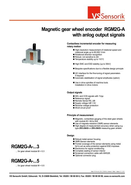
<strong>RGM2G</strong>-A-...3<br />
... for <strong>gear</strong> <strong>wheel</strong> module M = 0.3<br />
<strong>RGM2G</strong>-A-...5<br />
... for <strong>gear</strong> <strong>wheel</strong> module M = 0.5<br />
<strong>Magnetic</strong> <strong>gear</strong> <strong>wheel</strong> <strong>encoder</strong> <strong>RGM2G</strong>-A<br />
<strong>with</strong> <strong>anlog</strong> output signals<br />
Contactless incremental <strong>encoder</strong> for measuring<br />
rotary motion<br />
Output signals<br />
High-resolution measurement of rotational speed and<br />
rotational angle up to 60,000 1/min<br />
Rotational direction recognition<br />
Robust, not sensitive to dirt<br />
Temperature stability up to 110°C<br />
High EMC and ESD stability (up to 30kV)<br />
Bespoke specifications due to a flexible design principle<br />
I2C interface for the fine-tuning of signal parameters<br />
if required<br />
Automatic stabilisation of signal amplitudes (option)<br />
Use in drive spindles of machine tools<br />
Installation in drive motors<br />
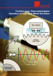
Principle of measurement<br />
Design<br />
SIN- and COS signals <strong>with</strong> 1Vpp<br />
Reference signal<br />
Remote Sense RS_UB<br />
Supply voltage UB = 5V<br />
Reverse voltage protection<br />
Short-circuit proof<br />
<strong>Magnetic</strong>, contactless gauging of the steel <strong>gear</strong> <strong>wheel</strong>s<br />
<strong>with</strong> module M = 0.3 or 0.5<br />
Use of magneto-resistive (GMR) sensor elements<br />
High degree of measurement accuracy when using e.g.<br />
type ZR3-256/Di or ZR5-256/Di measuring <strong>gear</strong> <strong>wheel</strong>s<br />
Robust metal sensor housing<br />
GMR-Sensor elements<br />
Frontal coverage of the sensor elements using metal<br />
foil to act as extra protection against ESD impulses<br />
Electronics for signal conditioning<br />
Complete sealing of sensor interior<br />
Screened connection cable <strong>with</strong> AWG28<br />
Optional connector plug<br />
Datei: <strong>VS</strong>-<strong>Sensorik</strong>_DB_E_<strong>RGM2G</strong>-A Version: 6 Blatt: 1 Datum: 01.11.2011<br />
<strong>VS</strong> <strong>Sensorik</strong> GmbH, Edisonstr. 19, D-33689 Bielefeld, Tel: 05205 / 99 88 69 0, Fax: 05205 / 99 88 69 99, www.vs-sensorik.com
eb( t)<br />
A( t)<br />
B( t)<br />
Ref( t)<br />
600<br />
400<br />
200<br />
0<br />
200<br />
400<br />
600<br />
Typical signal aspect. The signal spurs A, B and ref. are<br />
depicted. The area highlighted in grey shows the optimal<br />
position of the 0 channels for the ref. signals<br />
(area of unambiguousness).<br />
Connecting cable<br />
9 x AWG28<br />
21<br />
4<br />
14,5<br />
1<br />
0,5<br />
R 3,5<br />
10<br />
2<br />
3,94 +0,00<br />
-0,02<br />
35<br />
13<br />
19<br />
27<br />
t<br />
6<br />
45°<br />
ø5<br />
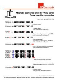
<strong>Magnetic</strong> <strong>gear</strong> <strong>wheel</strong> <strong>encoder</strong> <strong>RGM2G</strong>-A<br />
Specifications<br />
Position of the signal<br />
channels A, B & Ref.<br />
4,3<br />
R 3,5<br />
9,5<br />
15,3°<br />
Signal parameters<br />
Before delivery, each <strong>encoder</strong> is balanced at the nominal<br />
distance <strong>encoder</strong> - <strong>gear</strong> <strong>wheel</strong> do = 0.1mm (for M = 0.3)<br />
and 0.3mm (for M = 0.5) on optimal signal values (amplitude<br />
1 Vpp, offset 0 mV, phase 90°, unambiguousness<br />
of the reference pulse; signal aspect type - see figure).<br />
The signal parameters may deviate from the optimal<br />
values due to subsequent tolerances of attached parts,<br />
<strong>gear</strong> <strong>wheel</strong> quality and the influence of temperature and<br />
rotational speed.<br />
Signal type<br />
Signal amplitude A & B<br />
Amplitude differential A/B<br />
Phase A to B<br />
Offset - static<br />
Freq. of measurement<br />
General parameters<br />
Supply voltage UB<br />
Wattage<br />
Without load<br />
Operating temperature<br />
Storage temperature<br />
Optimal distance do<br />
<strong>encoder</strong> - <strong>gear</strong> <strong>wheel</strong><br />
Vibration resistance<br />
Shock resistance<br />
Type of protection<br />
Analog, differential signals<br />
SIN (spur A),<br />
COS (spur B)<br />
Ref. pulse<br />
Inverted signals A, B & Ref.<br />
1Vpp +/- 20% *<br />
0.9 ... 1.1 *<br />
90° +/- 1°<br />
+/- 20mV<br />
0 ... 200kHz<br />
* Conditions: UB = 5VDC; f < 50 kHz; automatic stabilisation<br />
of signal amplitudes is inactive (see page 4).<br />
5VDC +/- 5%<br />
50mA<br />
-20 ... 85°C<br />
(up to 100°C on request)<br />
-30 ... 110°C<br />
0.1 +/- 0.02mm for M = 0.3<br />
0.3 +/- 0.02mm for M = 0.5<br />
bis 200 m/s²<br />
bis 2000 m/s²<br />
IP68<br />
Datei: <strong>VS</strong>-<strong>Sensorik</strong>_DB_E_<strong>RGM2G</strong>-A Version: 6 Blatt: 2 Datum: 01.11.2011<br />
<strong>VS</strong> <strong>Sensorik</strong> GmbH, Edisonstr. 19, D-33689 Bielefeld, Tel: 05205 / 99 88 69 0, Fax: 05205 / 99 88 69 99, www.vs-sensorik.com
Gear Wheel<br />
do<br />
4<br />
4<br />
Reference mark<br />
The arrow indicates the direction of movement during<br />
counter-clockwise rotation of the <strong>gear</strong> <strong>wheel</strong> <strong>with</strong> a view<br />
to the <strong>encoder</strong>- illustrated in the example of the<br />
<strong>RGM2G</strong>-A-M... <strong>encoder</strong><br />
eb( t)<br />
A( t)<br />
B( t)<br />
Ref( t)<br />
9,5<br />
600<br />
400<br />
200<br />
0<br />
200<br />
400<br />
600<br />
15,5<br />
10<br />
Typical signal aspect during counter-clockwise rotation of<br />
the <strong>gear</strong> <strong>wheel</strong> <strong>with</strong> a view to the <strong>encoder</strong>. The signal spurs<br />
A, B and ref. are depicted. The area highlighted in grey<br />
shows the optimal position of the 0 channels of the<br />
ref. signals (area of unambiguousness).<br />
do<br />
t<br />
<strong>Magnetic</strong> <strong>gear</strong> <strong>wheel</strong> <strong>encoder</strong> <strong>RGM2G</strong>-A<br />
Assembly & Electrical connection<br />
14,5<br />
Assembly<br />
The <strong>encoder</strong> is assembled using the following procedure:<br />
1. Gauge blocks of the corresponding gauges do are<br />
located on the front side of the <strong>encoder</strong>.<br />
2. Fix the <strong>encoder</strong> using 2 M4 screws. The screws are<br />
still not firmly tightened. The <strong>encoder</strong> should be loose.<br />
3. Push the <strong>encoder</strong> slightly against the <strong>gear</strong> <strong>wheel</strong>.<br />
Completely tighten the screws alternately.<br />
4. After screwing the <strong>encoder</strong> tightly, remove the gauge<br />
block (spacer) in the upward direction.<br />
Distance <strong>encoder</strong> - <strong>gear</strong> <strong>wheel</strong> d (air gap)<br />
The optimal distance <strong>encoder</strong> - <strong>gear</strong> <strong>wheel</strong> do is:<br />
0.1 +/- 0.02mm for Modul M = 0.3<br />
0.3 +/- 0.02mm for Modul M = 0.5<br />
For this distance do the <strong>encoder</strong>s are balanced<br />
on optimal signal parameters. If required, the signal<br />
parameters can be adjusted via the I2C signal<br />
interface (see page 4).<br />
Cable assignment (Type P)<br />
On the output of the <strong>encoder</strong> is a screened cable <strong>with</strong> 9<br />
wires AWG28. The cable is assigned as follows:<br />
Signal A +<br />
Signal A -<br />
Signal B +<br />
Signal B -<br />
Signal Ref +<br />
Signal Ref -<br />
UB = 5VDC<br />
GND (0V)<br />
RS_5V<br />
brown<br />
green<br />
grey<br />
orange<br />
red<br />
black<br />
violet<br />
yellow<br />
blue<br />
The shield is connected to the casing on the <strong>encoder</strong><br />
side.<br />
Datei: <strong>VS</strong>-<strong>Sensorik</strong>_DB_E_<strong>RGM2G</strong>-A Version: 6 Blatt: 3 Datum: 01.11.2011<br />
<strong>VS</strong> <strong>Sensorik</strong> GmbH, Edisonstr. 19, D-33689 Bielefeld, Tel: 05205 / 99 88 69 0, Fax: 05205 / 99 88 69 99, www.vs-sensorik.com
Fine-tuning via the I2C-interface<br />
Gear <strong>wheel</strong><br />
1<br />
5<br />
Position and configuration of the connection sockets for<br />
the I2C interface on the back of the <strong>encoder</strong>.<br />
The connection sockets can be reached after partially<br />
removing the guard tag.<br />
8<br />
<strong>RGM2G</strong> - A -...<br />
installed in distance do<br />
to the <strong>gear</strong> <strong>wheel</strong><br />
<strong>Magnetic</strong> <strong>gear</strong> <strong>wheel</strong> <strong>encoder</strong> <strong>RGM2G</strong>-A<br />
I2C Interface<br />
Pin 1<br />
Alignment box<br />
PB-RGMA-USB or<br />
DCMU<br />
USB-cable<br />
I2C-Interface<br />
If required, the I2C interface can facilitate the fine-tuning<br />
of the parameters amplitude, offset and phase of the<br />
<strong>encoder</strong> signals A, B & Ref.<br />
Before dispatch, the utmost care is taken to ensure that<br />
all <strong>RGM2G</strong> <strong>encoder</strong> signals are working optimally. In spite<br />
of this, a single fine-adjustment of the signal parameters<br />
might be required. There are two possibilities for that:<br />
1. By “sensitively“ adjusting the position of the <strong>encoder</strong><br />
to the <strong>gear</strong> <strong>wheel</strong> you can set the best possible signal<br />
parameters. This method requires a lot of time and<br />
experience when installing the <strong>encoder</strong>.<br />
2. After installing the <strong>RGM2G</strong> <strong>encoder</strong> at the required<br />
distance do from the <strong>gear</strong> <strong>wheel</strong>, the required fine-adjustment<br />
of the <strong>encoder</strong> signals is quickly made via the<br />
I2C-interface.<br />
Automatic amplitude stabilisation (option)<br />
The signal electronics of the <strong>encoder</strong> enables the<br />
amplitude of signals A & B to be stabilised to a value of<br />
1 Vpp. This helps to offset any problems the axis or <strong>gear</strong><strong>wheel</strong><br />
has when rotating.<br />
Stabilisation of the amplitude can be configured via the<br />
I2C-interface.<br />
PC or laptop<br />
Operating system: Windows... (no Vista)<br />
USB connection 1.1 or 2.0<br />
Software: SPB-RGMA-USB<br />
Details on the alignment of the sensor<br />
parameter are given in the external<br />
Programming box PB-RGMA-USB-01<br />
instructions.<br />
Datei: <strong>VS</strong>-<strong>Sensorik</strong>_DB_E_<strong>RGM2G</strong>-A Version: 6 Blatt: 4 Datum: 01.11.2011<br />
<strong>VS</strong> <strong>Sensorik</strong> GmbH, Edisonstr. 19, D-33689 Bielefeld, Tel: 05205 / 99 88 69 0, Fax: 05205 / 99 88 69 99, www.vs-sensorik.com
<strong>Magnetic</strong> <strong>gear</strong> <strong>wheel</strong> <strong>encoder</strong> <strong>RGM2G</strong>-A<br />
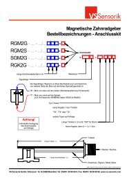
Order identifiers - Standard version<br />
<strong>RGM2G</strong> - A - - /P -<br />
Accessories<br />
Measuring <strong>gear</strong> <strong>wheel</strong>s: ZR3-256/Di or ZR5-256/Di<br />
Other types of <strong>gear</strong> <strong>wheel</strong>s on request.<br />
External interpolation box for the digitalisation<br />
and interpolation of the analogue <strong>encoder</strong> signals<br />
PB-RGMA-USB box <strong>with</strong> SPB-RGMA-USB software<br />
for the fine alignment of <strong>encoder</strong> signals via the<br />
I2C-interface<br />
Digital calibration and measurement unit DCMU for the<br />
visualisation, detailed analysis and fine alignment of the<br />
<strong>encoder</strong> signals.<br />
Type of the reference mark (e.g. "Z", "F" or "L"):<br />
Z - Type<br />
F - Type<br />
L - Type<br />
S - Type<br />
Y - Type<br />
? - other types on request<br />
3 - for <strong>gear</strong> <strong>wheel</strong> module M = 0.3<br />
5 - for <strong>gear</strong> <strong>wheel</strong> module M = 0.5<br />
Position of Signal tracks - "M" or "V":<br />
M Tracks A & B<br />
Ref.<br />
Connector plug<br />
Cable length in cm (e.g. "050" for 50cm)<br />
Optional: Number of teeth of the <strong>gear</strong> <strong>wheel</strong> N, if N is<br />
considerably different from 256 (e.g. "064" if N = 64)<br />
V Ref.<br />
Tracks A & B<br />
Datei: <strong>VS</strong>-<strong>Sensorik</strong>_DB_E_<strong>RGM2G</strong>-A Version: 7 Blatt: 5 Datum: 01.11.2011<br />
<strong>VS</strong> <strong>Sensorik</strong> GmbH, Edisonstr. 19, D-33689 Bielefeld, Tel: 05205 / 99 88 69 0, Fax: 05205 / 99 88 69 99, www.vs-sensorik.com
<strong>Magnetic</strong> <strong>gear</strong> <strong>wheel</strong> <strong>encoder</strong> <strong>RGM2G</strong>-A<br />
Order identifiers - Cable assignment<br />
<strong>RGM2G</strong> - A - - /P -<br />
Cable assignment<br />
Signal A +<br />
Signal A -<br />
Signal B +<br />
Signal B -<br />
Signal Ref +<br />
Signal Ref -<br />
UB = 5VDC<br />
GND (0V)<br />
RS_5V<br />
<strong>RGM2G</strong> - A - - /T -<br />
On the output of the <strong>encoder</strong> is a screened cable <strong>with</strong> 9<br />
wires AWG28. The cable is assigned as follows:<br />
Cable assignment<br />
A shielded cable <strong>with</strong> 9 wires, AWG28, is attached at the<br />
sensor output. The outer sheath is green according to<br />
RAL6018, based on DESINA specifications.<br />
The cable is assigned as follows:<br />
brown<br />
green<br />
grey<br />
orange<br />
red<br />
black<br />
violet<br />
yellow<br />
blue<br />
The shield is connected to the casing on the <strong>encoder</strong><br />
side.<br />
Signal A +<br />
Signal A -<br />
Signal B +<br />
Signal B -<br />
Signal Ref +<br />
Signal Ref -<br />
UB = 5VDC<br />
GND (0V)<br />
RS_5V<br />
white<br />
brown<br />
pink<br />
black<br />
grey<br />
yellow<br />
red<br />
blue<br />
green<br />
The shield is connected to the casing on the <strong>encoder</strong><br />
side.<br />
Datei: <strong>VS</strong>-<strong>Sensorik</strong>_DB_E_<strong>RGM2G</strong>-A Version: 6 Blatt: 6 Datum: 01.11.2011<br />
<strong>VS</strong> <strong>Sensorik</strong> GmbH, Edisonstr. 19, D-33689 Bielefeld, Tel: 05205 / 99 88 69 0, Fax: 05205 / 99 88 69 99, www.vs-sensorik.com
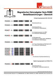
<strong>Magnetic</strong> <strong>gear</strong> <strong>wheel</strong> <strong>encoder</strong> RGM2 series<br />
Order identifiers - overview<br />
<strong>RGM2G</strong> - A - - /P -<br />
<strong>RGM2G</strong> - A - - /T -<br />
RGM2T - A - - /T -<br />
RGM2S - A - - /T -<br />
<strong>RGM2G</strong> - A - - /T - DM<br />
<strong>RGM2G</strong> - AS - - /P -<br />
RGM2S - AS - - /T -<br />
RGM2T - AS - - /T -<br />
RGM2S - AS - - /T -<br />
<strong>RGM2G</strong> - AS - - /T -<br />
<strong>RGM2G</strong> - D - - /P -<br />
... Standard version<br />
Analog output signals SIN, COS & Ref.<br />
... Standard version<br />
... With modified cable configuration<br />
... Increased working temperature up to 120°C<br />
... With modified cable configuration<br />
... With mounting base<br />
... Compatible <strong>with</strong> SIZAG sensor (SIEMENS)<br />
... With modified cable configuration<br />
... With 17-pin flange socket on mounting base<br />
... With modified cable configuration<br />
DM<br />
... With activated amplitude stabilisation<br />
Digital output signals according to RS432 (TTL)<br />
... Standard version<br />
... With integrated interpolation electronics<br />
Datei: <strong>VS</strong>-<strong>Sensorik</strong>_DB_E_<strong>RGM2G</strong>-A Version: 7 Blatt: Ü1 Datum: 01.11.2011<br />
<strong>VS</strong> <strong>Sensorik</strong> GmbH, Edisonstr. 19, D-33689 Bielefeld, Tel: 05205 / 99 88 69 0, Fax: 05205 / 99 88 69 99, www.vs-sensorik.com
<strong>Magnetic</strong> <strong>gear</strong> <strong>wheel</strong> <strong>encoder</strong> RGM2 series<br />
Order identifiers - overview<br />
<strong>RGM2G</strong> - A - - /SP -<br />
<strong>RGM2G</strong> - A - - /ST -<br />
RGM2T - A - - /ST -<br />
RGM2S - A - - /ST -<br />
<strong>RGM2G</strong> - A - - /ST - DM<br />
<strong>RGM2G</strong> - AS - - /SP -<br />
RGM2S - AS - - /ST -<br />
RGM2T - AS - - /ST -<br />
RGM2S - AS - - /ST -<br />
<strong>RGM2G</strong> - AS - - /ST -<br />
<strong>RGM2G</strong> - D - - /SP -<br />
... Standard version<br />
Analog output signals SIN, COS & Ref.<br />
... Standard version<br />
... With modified cable configuration<br />
... Increased working temperature up to 120°C<br />
... With modified cable configuration<br />
... With mounting base<br />
... Compatible <strong>with</strong> SIZAG sensor (SIEMENS)<br />
... With modified cable configuration<br />
... With 17-pin flange socket on mounting base<br />
... With modified cable configuration<br />
DM<br />
... With activated amplitude stabilisation<br />
Digital output signals according to RS432 (TTL)<br />
... Standard version<br />
... With integrated interpolation electronics<br />
Datei: <strong>VS</strong>-<strong>Sensorik</strong>_DB_E_<strong>RGM2G</strong>-A Version: 7 Blatt: Ü2 Datum: 01.11.2011<br />
<strong>VS</strong> <strong>Sensorik</strong> GmbH, Edisonstr. 19, D-33689 Bielefeld, Tel: 05205 / 99 88 69 0, Fax: 05205 / 99 88 69 99, www.vs-sensorik.com
21<br />
4<br />
Anschlusskabel<br />
connecting cable<br />
9 x AWG28<br />
1<br />
0,5<br />
R 3,5<br />
14,5<br />
10<br />
2<br />
3,94 +0,00<br />
-0,02<br />
Material<br />
35<br />
13<br />
19<br />
27<br />
6<br />
45°<br />
ø4,5<br />
<strong>VS</strong> <strong>Sensorik</strong> GmbH<br />
Lage der Signalspuren<br />
Position of the signal channels<br />
A, B & Ref.<br />
Allgemeintoleranzen<br />
ISO 2768 - f<br />
4,3<br />
R 3,5<br />
9,5<br />
15,3°<br />
Dateiname Datum<br />
Maßstab<br />
RGM_ax 27.10.09 2:1<br />
<strong>RGM2G</strong>-A ... /...<br />
09<strong>VS</strong>042701<br />
Version Blatt<br />
1 1
21<br />
4<br />
1<br />
0,5<br />
R 3,5<br />
14,5<br />
10<br />
2<br />
3,94 +0,00<br />
-0,02<br />
Material<br />
35<br />
13<br />
19<br />
27<br />
6<br />
45°<br />
<strong>VS</strong> <strong>Sensorik</strong> GmbH<br />
Lage der Signalspuren<br />
Position of the signal channels<br />
A, B & Ref.<br />
9,5<br />
R 3,5<br />
Allgemeintoleranzen<br />
ISO 2768 - f<br />
16,75<br />
4,3<br />
ø4,50<br />
3,50<br />
Anschlusskabel<br />
connecting cable<br />
9 x AWG28<br />
Dateiname Datum<br />
Maßstab<br />
RGM_tan 27.09.2009 2:1<br />
<strong>RGM2G</strong>.../S...<br />
09<strong>VS</strong>091709<br />
Version Blatt<br />
1 1