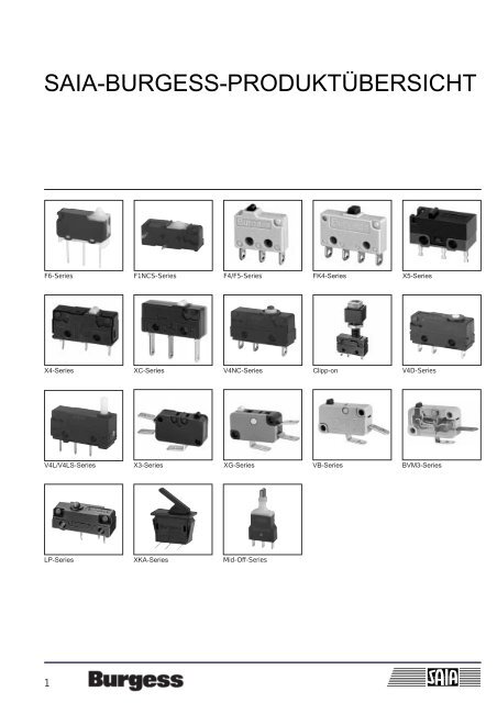
SAIA-BURGESS-PRODUKTÜBERSICHT - Wagner GmbH
SAIA-BURGESS-PRODUKTÜBERSICHT - Wagner GmbH
SAIA-BURGESS-PRODUKTÜBERSICHT - Wagner GmbH

You also want an ePaper? Increase the reach of your titles
YUMPU automatically turns print PDFs into web optimized ePapers that Google loves.
<strong>SAIA</strong>-<strong>BURGESS</strong>-<strong>PRODUKTÜBERSICHT</strong><br />
F6-Series F1NCS-Series F4/F5-Series<br />
X4-Series<br />
V4L/V4LS-Series<br />
1<br />
XC-Series<br />
X3-Series<br />
LP-Series XKA-Series<br />
V4NC-Series Clipp-on V4D-Series<br />
XG-Series VB-Series<br />
Mid-Off-Series<br />
FK4-Series X5-Series<br />
BVM3-Series
Terminology<br />
OPERATING CHARACTERISTICS<br />
Free Position<br />
the position of the actuator when no external<br />
force is applied.<br />
Pretravel<br />
movement of the switch actuator between<br />
free and operating position.<br />
Operating Position<br />
the position of the actuator when contact<br />
changeover takes place.<br />
Release Position<br />
the position of the actuator when the switch<br />
mechanism resets.<br />
Movement Differential<br />
the distance between operating and release<br />
position.<br />
Overtravel<br />
movement of the switch actuator beyond the<br />
operating position.<br />
Total Travel<br />
the sum of pre-travel and overtravel.<br />
Actuating Force<br />
the force required to move the actuator from<br />
the free to the operating position.<br />
Release Force<br />
the value to which the applied force must be<br />
reduced to allow the mechanism to reset after<br />
operation<br />
Force Differential<br />
The difference between the values of actuating<br />
and release forces.<br />
Please see drawings on this page.<br />
2<br />
Force required to operate actuator or auxiliary actuator<br />
Maximum Force<br />
Actuating Force<br />
Force<br />
Differential<br />
Release<br />
Force<br />
Free Position<br />
Post-release travel<br />
Position of actuator or auxiliary actuator<br />
Description of switch positions and micro switch forces<br />
Actuator or<br />
auxiliary actuator<br />
Guide<br />
Pretravel<br />
Operating Position<br />
Release Position<br />
Free position Operating Position<br />
Operation of actuator or auxiliary actuator<br />
Movement<br />
Differential<br />
Pretravel Overtravel<br />
Overtravel<br />
Total Travel<br />
Release Travel<br />
Movement<br />
Differential<br />
Release Travel<br />
Final Position<br />
Post-release<br />
Travel<br />
Final position Release Force<br />
Total Travel
SWITCH TECHNOLOGY<br />
TECHNICAL TERMS<br />
Butt Contacts<br />
Contacts which make at one point and maintain<br />
their initial relationship without further<br />
movement until they are opened.<br />
Wiping Contact<br />
A moving contact mechanically arranged to<br />
slide across the fixed contact during pretravel<br />
and overtravel.<br />
Clearance Distance<br />
The distance in air between current carrying<br />
parts of opposite polarity or between any current<br />
carrying part and an earthed (grounded)<br />
metal plate to which the switch is attached.<br />
Creepage Distance<br />
The path along the surface of insulating material<br />
between current carrying parts of opposite<br />
polarity or between any current carrying part<br />
and an earthed (grounded) metal plate to<br />
which the switch is attached.<br />
Insulation Resistance<br />
Resistance as measured between the<br />
normally-open and normally-closed terminals,<br />
3<br />
or between all terminals connected together<br />
and a metal plate to which the switch is<br />
mounted. In dry condition the value would be<br />
expected to be greater than 5000 megohms.<br />
Single Throw<br />
A switch which provides an ON-OFF or OFF-<br />
ON function but does not change over from<br />
one conductor to another. Such switches are<br />
usualIy referred to as being «normalIy-closed<br />
only» or «normally-open only». C2 signifies<br />
«Normally-closed only»; C4 signifies «normally-open<br />
only».<br />
Switching Cycle<br />
One complete switching operation, from free<br />
position into overtravel and back through<br />
release position to free position. Mechanical<br />
life estimates reflect the number of switching<br />
cycles expected to be accomplished before<br />
operating characteristics become impaired.<br />
Switch Resistance<br />
The total resistance offered by a switch in<br />
a circuit, as measured from terminal, through<br />
mating contacts, to terminal.<br />
Transit Time<br />
The time taken by the moving contact in<br />
snap-action switch mechanism to move from<br />
one stable position to another.<br />
ELECTRICAL RATINGS<br />
Recommended maximum electrical ratings<br />
are quoted for each product group.<br />
These ratings are based on the results of controlled,<br />
accelerated, laboratory-type tests and<br />
are regarded as safe working maxima for<br />
most applications.<br />
The performance of switches is, however, influenced<br />
by conditions pertaining on site e.g.<br />
frequency of operation, type of load, amount<br />
of actuator travel used, temperature and humidity,<br />
etc.<br />
The characteristics of micro switches rely<br />
upon mechanisms having small contact<br />
separation. Because of this, it is always<br />
desirable to check on the arcing potential of<br />
your circuit and to suppress those elements<br />
which could cause excessive arcing.<br />
SWITCH LIFE<br />
The electrical life of a switch is dependent<br />
upon frequency of operation, the on-off ratio<br />
of operation, the nature of the load, arc suppression<br />
and other circuit details, the amount<br />
of actuator travel used, ambient humidity and<br />
temperature and many other site factors, none<br />
of which is within the switch manufacturers<br />
competence to control. Electrical life test information<br />
relates to laboratory controlled<br />
tests.<br />
Individual assessments, for specific applications<br />
where all relevant data is available, are<br />
possible and can be undertaken by <strong>SAIA</strong>-<br />
Burgess Electronics upon request.<br />
For details of the mechanical life of individual<br />
switches, please refer to the appropriate<br />
specification sheet.
APPLICATION TECHNOLOGY<br />
Shock and Vibration<br />
If switches are likely to be subjected to shock<br />
or vibration, select models with the highest<br />
available actuating force. Switches in this<br />
Catalogue possess low mass mechanisms<br />
which are inherently resistant to shock and<br />
vibration.<br />
If practicable, the switches should be<br />
mounted in such a position that the line of<br />
acceleration is at right angles to the travel of<br />
the plunger. The maximum available overtravel<br />
should be used.<br />
Capacitive Loads<br />
These can generate very high inrush peaks<br />
and care should therefore be exercised to<br />
avoid contact welding.<br />
Direct Current<br />
Direct Current (DC) ratings are provided for<br />
each product group listed in this Catalogue.<br />
The values stated should not be exceeded if<br />
destructive arcing and contact welding are to<br />
be avoided.<br />
Some form of arc suppression is recommended<br />
when switches are used in DC circuits<br />
containing inductive devices wired in series<br />
with the switch and the supply. Five common<br />
arc suppression circuits which may be used to<br />
alleviate the effects of arcing on the switch<br />
contacts are shown here. The values of the<br />
components used depend on circuit<br />
conditions.<br />
4<br />
Inductive Loads<br />
Electrical Ratings Tables included in this<br />
Catalogue provide data for switches used to<br />
control inductive circuits at a power factor of<br />
0.5<br />
Lamp Loads<br />
Because of the very high inrush currents<br />
associated with incandescent lamps, applications<br />
should be subject to individual assessment.<br />
Logic Circuits<br />
To provide reliable switching, the use of gold<br />
plated contacts is recommended. Three types<br />
of construction are used:<br />
AU: signifies gold plating on nickel underlay<br />
GP: indicates gold-plated silver contacts<br />
GPX: relates to gold-plated cross point<br />
contacts<br />
Installation recommendations<br />
The following notes are intended merely to<br />
stress the most important and general<br />
aspects of good switch installation procedure<br />
and to provide some helpful additional information.<br />
Safety Considerations<br />
Installation should only be carried out by competent<br />
personnel.<br />
Position and Operation<br />
Operating position is the significant factor to<br />
consider when positioning any snap-action<br />
switch. The actuating medium must be able to<br />
operate the switch through this position into<br />
overtravel and then to retract far enough to<br />
allow the switch to regain its free position.<br />
Mounting<br />
Side mounting switches should be mounted<br />
on smooth, firm, flat surfaces using the recommended<br />
size of screw. Avoid over-tightening<br />
the screws. For added security, they<br />
should be locked using epoxy resin. Do not<br />
attempt to enlarge switch mounting holes and<br />
avoid over stressing the switch. Use insulating<br />
material between switch and metallic plates to<br />
increase clearance on switches with open<br />
terminals.<br />
Mounting holes and Screw sizes<br />
Nominal hole Metric Unified Thread<br />
Diameter Screw Screw<br />
(mm) (in)<br />
2.25 0.09 M 2 #2<br />
2.9 0.11 M 2.5 #4<br />
Mounting-Screw Torque<br />
The following provides guidance when using<br />
mild steel screws<br />
M 2 or # 2 screws 0.12 Nm<br />
M 2.5, M3 or # 4 screws 0.5 Nm<br />
Connections<br />
When soldering, avoid over-heating any part<br />
of the switch insulation. In certain circumstances,<br />
it may be advisable to use a heat shunt.<br />
For optimum mechanical strength, the conductor<br />
should be wrapped round the tip of the<br />
terminal taking care to avoid loose strands of<br />
wire. The soldering iron bit should be applied<br />
to the end of the terminal while simultaneously<br />
applying solder. Remove the iron as soon as<br />
the solder has wetted the conductor and terminal<br />
end. A soldering iron bit temperature of<br />
370°C applied for a maximum of 2-3 seconds<br />
should be adequate.
CONTACT MATERIALS<br />
Gold<br />
Gold plated contacts are recommended for<br />
switches to be used in low voltage control or<br />
logic circuits, especially when long periods of<br />
inactivity are envisaged. Gold flash, a thinner<br />
deposit, is applied to certain switch terminals<br />
to ensure good solderability even after prolonged<br />
storage.<br />
How to determine the contact material<br />
for <strong>SAIA</strong> XG/XC-series only<br />
The selection of the appropriate contact<br />
material will depend on a number of factors:<br />
• current and voltage<br />
• resistive or inductive load<br />
• inrush current peak<br />
• frequency of switching operations<br />
• atmospheric conditions<br />
• required switching reliability<br />
Pure silver contacts (standard)<br />
<strong>SAIA</strong>-Burgess Snap-Action Switches are<br />
normally equipped with pure silver contacts<br />
(Ag999). These are suitable for most<br />
applications and have satisfactory electrical<br />
and thermal properties.<br />
Gold-plated contacts<br />
Gold-plated contacts (4 µm) are used for low<br />
currents of a few mA and voltages below<br />
about 20 V (for DC and AC) and for<br />
sulphurous atmospheres. They are unsuitable<br />
for higher breaking capacities.<br />
5<br />
Silver-cadmium oxide contacts<br />
Silver-cadmium oxide (AgCdO 90/10) contacts<br />
should be used where high inrush current<br />
peaks (30A or more) are switched on as they<br />
tend to weld less at high current loads. They<br />
can resist peaks of 80A or more for several<br />
ms provided that they are used with a <strong>SAIA</strong>-<br />
Burgess Snap-Action Switch with high operating<br />
and contact force (80cN in the free<br />
position and total-travel position).<br />
At high breaking capacities, switches fitted<br />
with such contacts have about 50% longer life<br />
expectancy than those fitted with pure silver<br />
contacts. Normally, silver-cadmium oxide<br />
contacts are not suitable for voltages under<br />
50V.
SERVICE RECOMMENDATIONS<br />
Maintenance<br />
<strong>SAIA</strong>-Burgess switches are not usermaintainable<br />
but they should be kept in a<br />
reasonably clean, paint-free condition,<br />
especially in the actuator area. Regular<br />
checks should be made on mounting security<br />
and on the actuating medium to switch<br />
actuator relationship.<br />
Switch Life<br />
The effective life of any switch will depend<br />
upon the model selected, the number and<br />
frequency of operations, circuit conditions<br />
and the severity of the environment. Switch<br />
replacement should be a matter of routine.<br />
6<br />
SWITCH ACTUATION<br />
Simple actuating plunger<br />
Actuating plungers should be operated in the<br />
direction of their axis. The plungers of the<br />
switch series may also be actuated laterally<br />
by cams at a recommendet maximum angle<br />
of 30°.<br />
Actuation by sliding cams.<br />
max. 30º<br />
Actuating levers<br />
All types of Iever (straight, roller, cam-follower)<br />
fitted to <strong>SAIA</strong>-Burgess Snap-Action Switches<br />
are made of stainless steel. Cam-follower<br />
levers are particularly well suited for use with<br />
plastic actuating cams.<br />
If roller or cam-follower levers are approached<br />
in the reverse direction, care must be taken<br />
to ensure that the angle of approach is small<br />
enough not to jam the lever.<br />
Actuation by cams<br />
Abrupt actuation or release of levers shortens<br />
life of the switches.<br />
For this reason cams should preferably provide<br />
a continuous movement. Ideally they<br />
should be of cycloidal form.<br />
,<br />
Long roller lever with continuous actuation.
HEALTH AND SAFETY<br />
<strong>SAIA</strong>-Burgess Electronics have ensured, so<br />
far as it is reasonably practicable, that their<br />
products as described in this Catalogue or in<br />
other current Company publications, or as<br />
specified on Company Installation Drawings,<br />
have been so designed and constructed as to<br />
be safe and without risk to health when<br />
installed by suitably qualified personnel in<br />
accordance with relevant legislation, codes of<br />
practice, regulations (including IEE Wiring<br />
Regulations), the installation recommendations<br />
offered by the Company and the<br />
accepted rules of the art. Their usage should<br />
be confined within the ratings, limitations and<br />
parameters of application indicated in this<br />
Catalogue and elsewhere.<br />
<strong>SAIA</strong>-Burgess Electronics or their<br />
representatives are available at all times to<br />
provide further information and guidance.<br />
7<br />
ENVIRONMENTAL PROTECTION<br />
Protection Classifications<br />
The catalogued range of <strong>SAIA</strong>-Burgess<br />
switches is covered by just four codes.<br />
IP40<br />
(no corresponding NEMA type)<br />
Adequate protection against solids such as<br />
probing fingers and small wires. Liquids, however,<br />
can gain access and, unless externally<br />
protected, the switches should be mounted in<br />
dry or well-sheltered positions.<br />
IP54K<br />
(corresponding generally with NEMA type 4)<br />
Good protection against solid foreign bodies<br />
and liquid spray of an intensity which could be<br />
expected to be emitted from a watering can.<br />
The spray may come from any angle. Switches<br />
may be used out of doors if sheltered<br />
from the worst of the elements or on factory<br />
machines subjected to normal washing down<br />
procedures.<br />
IP6K5<br />
(corresponding generally with NEMA type 13)<br />
Complete protection against solids, including<br />
dust, and against liquid splashing of the<br />
severity to be expected if the switch was<br />
turned round and round under a cold water<br />
tap. This IP code is nominated in DIN<br />
specifications for limit switches.<br />
IP6K7<br />
(corresponding generally with NEMA type 6)<br />
Similar protection to IP65 but this code is<br />
reserved for switches which are factory sealed<br />
and pressure tested.<br />
Switches should not be immersed in any<br />
liquid.<br />
Working Temperatures<br />
For details of the working temperatures applicable<br />
to individual types, refer to the appropriate<br />
specification sheet. Special versions suitable<br />
for temperatures outside these ranges<br />
are possible. Details from <strong>SAIA</strong>-Burgess<br />
Electronics on request.<br />
All quoted temperatures assume stable<br />
operation. They do not imply an ability to<br />
withstand excessive cycling within the range.<br />
APPROVALS<br />
<strong>SAIA</strong>-Burgess Electronics is listed in the BSI<br />
Register of Firms of Assessed Capability<br />
(Registration No. FM/09808) in accordance<br />
with:<br />
BS EN ISO 9001-1994.
F6-Series<br />
8<br />
F6<br />
7.35 (.29)<br />
14.7 (.57)<br />
12.7 (.58)<br />
5.8<br />
(.23)<br />
R1<br />
6.85 (2.7) 8.9 (.35)<br />
A<br />
B<br />
5.4<br />
(2.1)<br />
A = Operating position10.8 mm (.425 in)<br />
B = Free position 11.3 mm (.445 in)<br />
Datum for free position and operating position is button edge of base (stand-off’s).<br />
Switch solution in smallest dimensions<br />
With the F6 we are expanding our product<br />
range with a new micro switch type of special<br />
class.<br />
The approved process of the Twin-Shot- and<br />
Insert-Moulding in our switch production<br />
allows us to minimize the number of parts,<br />
process steps and guarantees the highest<br />
process reliability and quality of our automatic<br />
assembled F6 switch.<br />
Due to the Twin-Shot-Moulding lid, sealing<br />
and cowl are manufactured on a single tool.<br />
The insert moulded terminals allows to give<br />
up the complicated gluing process.<br />
Special characteristics of the F6<br />
• Silicon free materials<br />
• Side actuation of 40° directly on plunger<br />
possible due to:<br />
– POM plunger material with very low sliding<br />
friction<br />
– spherical plunger head<br />
– special plunger leanding concept<br />
• Long overtravel despite small construction<br />
dimensions<br />
• Ice break levers<br />
• Nominal currents of 5 mA to 3 A<br />
with 12/24 VDC<br />
• 5-parts-concept due to Twin-Shot-Moulding<br />
and Insert-Moulding = Elimination of<br />
tolerance chains and high process reliability<br />
• Latest manufacturing technology without<br />
gluing, without mechanical fitting between<br />
cowl and lid
Specifications<br />
Operating temperature<br />
-40°C up to +85°C<br />
Type of protection:<br />
IP6K7<br />
Mechanical life:<br />
Up to 1 mio. cycles<br />
Mechanism:<br />
leaf spring mechanism<br />
Actuators:<br />
Ice break levers<br />
Materials:<br />
Cowl: TPE<br />
Plunger: POM<br />
Lid: PP GF30<br />
Base: PTB<br />
Terminals: CuZn silver plated<br />
Contacts: AgNi 0.15<br />
Circuit diagram F6T85<br />
9<br />
<br />
Common<br />
Normally<br />
open<br />
Normally<br />
closed<br />
Recommended Max. Electrical Ratings<br />
Voltage<br />
VAC<br />
250 50<br />
12 to 24 2<br />
Resistive load<br />
mA<br />
Recommended Min. Electrical Ratings<br />
Voltage Resistive load<br />
VAC<br />
mA<br />
Twin-Shot-Moulding<br />
Insert Moulding<br />
Recommended Max. Electrical Ratings<br />
Voltage Resistive load Cycles<br />
VDC<br />
mA<br />
12 to 24 20<br />
2000<br />
12 to 24 2<br />
Resistive load<br />
mA<br />
F6<br />
500’000<br />
50’000<br />
Recommended Min. Electrical Ratings<br />
Voltage<br />
VDC<br />
Lid Cowl<br />
Sealing<br />
Insert moulded<br />
terminals
Product Range<br />
F6<br />
Operating Characteristics<br />
Actuator Reference Actuating<br />
Force<br />
Maximum<br />
N (ozf)<br />
10<br />
Release<br />
Force<br />
Minimum<br />
N (ozf)<br />
Free<br />
Position<br />
Maximum<br />
mm (in)<br />
Operating<br />
Position<br />
mm (in)<br />
Movement<br />
Differential<br />
Maximumm<br />
m (in)<br />
Plunger F6T85 1.4 (5.03) 0.2 (0.71) 11.3 10.8 ± 0.2 0.2 ± 0.05<br />
(.425 ± .008) (.008 ±.0019)<br />
H<br />
Lever<br />
F6T85H For positions and forces of this actuator please contact Burgess.<br />
R 1,3<br />
(.051)<br />
Datum for free position and operating position is button edge of base (stand-off’s).<br />
Total<br />
Travel<br />
mm<br />
max.<br />
2.0<br />
(.078)
Ordering References<br />
Switch range: F6<br />
Terminal Types<br />
Actuators<br />
No symbol = Plunger<br />
H Plain lever<br />
Mounting<br />
No symbol = without pegs<br />
B… Several mounting pegs with a max. length of 4.9 mm (.1929 in) and<br />
max. Ø of 2.2 mm (.0866 in) on request.<br />
11<br />
T85<br />
4<br />
(.16)<br />
6.85<br />
(.27)<br />
T8 T84<br />
T81<br />
2.85<br />
(.112)<br />
t851.75<br />
(.068)<br />
T82<br />
2 (.078)<br />
F6<br />
F6
F1NCS-Series<br />
F1NCST8C2<br />
12<br />
Free Position<br />
max. 8.6<br />
(max. .338)<br />
Operating Position<br />
5.4<br />
(.214)<br />
3.45<br />
(.136)<br />
3.35<br />
(.132)<br />
0.9<br />
(.035)<br />
0.8<br />
(.031)<br />
2<br />
5.04 ± 0.15<br />
(.198 ± .006)<br />
1.4 ± 0.1<br />
(.055 ± .004)<br />
4.1 ±0.1<br />
(.161 ±.004)<br />
1<br />
0.9<br />
(.035)<br />
2.65<br />
(.104)<br />
14.4 ± 0.15<br />
(.567 ± .006)<br />
4.8<br />
(.189)<br />
1.4<br />
(.055)<br />
0.5<br />
(.019)<br />
4.7<br />
(.185)<br />
4.2<br />
(.165)<br />
5.2<br />
(.204)<br />
1.2 ± 0.1<br />
(.047 ± .004)<br />
Ø 1.4<br />
(Ø .055)<br />
2.5<br />
(.098)<br />
3.6<br />
(.141)<br />
°<br />
1<br />
±<br />
°<br />
3<br />
With the introduction of the F1NCS, <strong>SAIA</strong>-<br />
Burgess has once more set the standard for<br />
the miniaturisation of switching elements for<br />
electronic equipment.<br />
The new ultra-miniature switches offer the<br />
user many advantages:<br />
• 10% smaller than the F1T8.<br />
• Flux-proof terminal entries.<br />
• With minimized number of parts and<br />
process steps due to the Twin-Shot-<br />
Moulding.<br />
• Latest manufacturing technology without<br />
gluing, mechanical fitting between cowl and<br />
lid.
Specifications<br />
Temperature Range:<br />
-40°C to +85°C<br />
Type of Protection:<br />
Enclosure IP54<br />
Mechanical Life:<br />
10 7 cycles minimum (impact-free actuation)<br />
Mechanism:<br />
Snap-action, coil spring mechanism with<br />
stainless steel spring. Single-pole changeover<br />
contact.<br />
Contacts:<br />
Fine silver<br />
Gold plate on silver<br />
Mounting:<br />
PCB. Locating pins on housing<br />
Actuators:<br />
Plain lever; Cam follower<br />
Materials:<br />
Cowl: TPE<br />
Plunger: POM<br />
Lid: PP GF30<br />
Base: PA66 GF30<br />
Terminals: PCB silver plated<br />
Circuit diagram<br />
F1NCST8<br />
Change-over<br />
13<br />
Normally closed<br />
Normally open<br />
Common<br />
Recommended Max. Electrical Ratings<br />
Voltage<br />
VAC<br />
125<br />
250<br />
up to<br />
30<br />
50<br />
75<br />
125<br />
Resistive load<br />
A<br />
1<br />
1<br />
Resistive load<br />
A<br />
2<br />
0.5<br />
0.25<br />
0.2<br />
1<br />
1<br />
Recommended Max. Electrical Ratings<br />
Voltage<br />
VDC<br />
Inductive load<br />
Inductive load<br />
A<br />
2<br />
0.5<br />
0.25<br />
0.03<br />
The breaking capacities in the table refer to<br />
silver contacts. For gold contacts see the<br />
text above right.<br />
A<br />
Gold-plated contacts are intended for use in<br />
signal circuits where the energy being<br />
switched is at the milliwatt level. Power being<br />
switched must be limited in order to avoid<br />
overheating and possible dispersal of the gold<br />
from the contact area.<br />
See also page 5.<br />
F1NCS
Product Range<br />
F1NCS<br />
Operating Characteristics<br />
Actuator Reference Actuating<br />
Force<br />
Maximum<br />
N (ozf)<br />
14<br />
Release<br />
Force<br />
Minimum<br />
N (ozf)<br />
Free<br />
Position<br />
Maximum<br />
mm (in)<br />
Operating<br />
Position<br />
mm (in)<br />
Movement<br />
Differential<br />
Maximum<br />
mm (in)<br />
Plunger F1NCST8 2.0 (7.2) 0.2 (0.72) 6.5 5.9 (0.23) 0.2<br />
(0.26) ± 0.2 (± 0.008) (0.008)<br />
A1- F1NCST8A1 0.6 (2.2) 0.09 (0.32) 10.5 7.6 (0.30) 0.7<br />
Lever (0.41) ± 1.2 (±0.05) (0.03)<br />
Width of lever<br />
3.0 mm (.12)<br />
AC- F1NCST8AC 0.6 (2.2) 0.09 (0.32) 13.3 10.1 (0.40) 0.7<br />
Lever (0.52) ± 1.2 (±0.05) (0.03)<br />
Width of lever<br />
3.0 mm (.12)<br />
Datum for Free Position and Operating Position: base of switch opposite plunger.<br />
Over<br />
Travel<br />
Flush with case.<br />
The case should not be used as an end stop.
Ordering References<br />
Switch range: F1NCS<br />
Terminal Type<br />
T8 = PCB<br />
see page 8<br />
Circuits<br />
No symbol = Changover<br />
C2 Normally closed<br />
C4 Normally open<br />
Actuators<br />
No symbol = Plunger<br />
A1 Plain lever 18.0 mm (.71 in)<br />
AC Cam follower 18.5 mm (.73 in)<br />
Contacts<br />
No symbol = Fine silver<br />
GP Gold plate on silver<br />
15<br />
F1NCS<br />
F1NCS
F4/F5-Series<br />
16<br />
F4T6<br />
F4T7<br />
F5T8<br />
Among the world’s smallest switches with<br />
power capabilities, these units have surprisingly<br />
high current ratings and are engineered<br />
with precision for long and reliable life.<br />
The use of a double pivot mechanism provides<br />
a wiping action of the contacts to improve<br />
weld-breaking capability. The proven<br />
high capacity stainless steel coil spring<br />
mechanism provides maximum service life and<br />
reliability.<br />
The F4 range is designed for side mounting<br />
with two M2 screws. The much-reduced size<br />
of the F5 is achieved by the omission of<br />
mounting holes. It is intended for use on<br />
printed circuit boards.
Specifications<br />
Housing:<br />
Glass fibre reinforced Polyamide (PA 6.6)<br />
Plunger:<br />
Polyamide (PA 6.6)<br />
Mechanism:<br />
Double pivot, snap-action coil spring mechanism<br />
with stainless steel spring.<br />
Single pole changeover or normally open<br />
Contacts:<br />
Fine silver<br />
Gold plate on silver<br />
Terminals:<br />
F4T6: 2.0 mm faston<br />
F4T7: Solder<br />
F5T8: PCB<br />
All terminals are gold flashed.<br />
Temperature Range:<br />
-40°C to +85°C<br />
Mechanical Life:<br />
10 7 cycles minimum (impact free actuation)<br />
Type of protection:<br />
Enclosure – IP40<br />
Mounting:<br />
F4: Side mounting<br />
F5: PCB<br />
Actuators:<br />
Plain lever; Cam follower<br />
Accessories:<br />
Lug mounting frame, insulating sheet,<br />
spring-leaf actuator<br />
Approvals:<br />
UL; CSA;<br />
Circuit diagram F4/F5<br />
17<br />
Common<br />
Change-over<br />
Normally<br />
closed<br />
Normally<br />
open<br />
Recommended Max. Electrical Ratings<br />
Voltage<br />
VAC<br />
125<br />
250<br />
Recommended Max. Electrical Ratings<br />
Voltage<br />
VDC<br />
up to<br />
30<br />
50<br />
75<br />
125<br />
250<br />
Resistive load<br />
A<br />
5<br />
5<br />
Resistive load<br />
A<br />
5<br />
2<br />
1<br />
0.5<br />
0.25<br />
Inductive load<br />
A<br />
5<br />
5<br />
Inductive load<br />
A<br />
5<br />
2<br />
1<br />
0.06<br />
0.03<br />
The breaking capacities in the table refer to<br />
silver contacts. For gold contacts see the<br />
text above right.<br />
Gold-plated contacts are intended for use in<br />
signal circuits where the energy being switched<br />
is at the milliwatt level. Power being<br />
switched must be limited in order to avoid<br />
overheating and possible dispersal of the gold<br />
from the contact area.<br />
See also page 5.<br />
F4<br />
F5
Product Range<br />
F4<br />
Operating Characteristics<br />
F5<br />
Actuator Reference Actuating<br />
Force<br />
Maximum<br />
N (ozf)<br />
Plunger F5 T8 1.4 (5) 0.25 (0.9) 9.5 8.75 (0.34) 0.13<br />
(0.37) ± 0.3 (± 0.012) (0.005)<br />
F4T6 1.4 (5) 0.25 (0.9) 8.8 8.1 (0.32) 0.13<br />
F4T7 (0.35) + 0.3/– 0.2<br />
(+0.01/– 0.008)<br />
(0.005)<br />
Y1- F5T8Y1 0.6 (2.2) 0.07 (0.25) 10.7 8.8 (0.35) 0.7<br />
Lever (0.42) ± 1.1 (± 0.04) (0.03)<br />
Width of lever<br />
3.0 mm (.12)<br />
18<br />
<br />
<br />
F4T6Y1 0.6 (2.2) 0.07 (0.25) 10.0 8.2 (0.32) 0.7<br />
F4T7Y1 (0.39) + 1.0/– 0.7<br />
(+ 0.04/–0.03)<br />
(0.03)<br />
YC-Lever F5T8YC 0.7 (2.5) 0.09 (0.32) 12.4 10.9 (0.43) 0.45<br />
(0.49) ± 0.85 (± 0.03) (0.02)<br />
Width of lever<br />
3.0 mm (.12)<br />
Datum for Free Position and Operating Position<br />
F4 – Centre of fixing hole<br />
F5 – Terminal shoulder<br />
<br />
Release<br />
Force<br />
Minimum<br />
N (ozf)<br />
Free<br />
Position<br />
Maximum<br />
mm (in)<br />
Operating<br />
Position<br />
mm (in)<br />
Movement<br />
Differential<br />
Maximum<br />
mm (in)<br />
F4T6YC 0.7 (2.5) 0.09 (0.32) 11.7 10.3 (0.41) 0.45<br />
F4T7YC (0.46) + 0.8 /– 0.55<br />
(+ 0.03/– 0.02)<br />
(0.02)<br />
Over<br />
Travel<br />
Flush with case.<br />
The case should not be used as an end stop.
Ordering References<br />
Switch range: F4 Side mounting<br />
F5 PCB mounting<br />
Terminal type<br />
T6 = Faston<br />
T7 = Solder<br />
T8 = PCB<br />
see page 12<br />
Circuit No symbol = Changover<br />
C2 Normally closed* *(F4 only)<br />
C4 Normally open<br />
Actuators<br />
No symbol = Plunger<br />
Y1 Plain lever 21.0 mm (.83 in)<br />
YC Cam follower 16.9 mm (.67 in)<br />
Contacts<br />
No symbol = Fine silver<br />
GP Gold plate on silver<br />
19<br />
F4<br />
F5
FK4-Series<br />
20<br />
FK4T6<br />
FK4T7<br />
FK4T8<br />
Moulded-cased, single-pole changeover,<br />
snap-action switches which open or close the<br />
conductors at two points, thereby increasing<br />
the available contact separation.<br />
FK4 switches are slightly smaller than<br />
V4 Series although mounting positions interchange.
Specifications<br />
Housing:<br />
Glass fibre reinforced Polyamide (PA 6.6)<br />
Plunger:<br />
Polyamide (PA 6.6); Polyacetal (POM) for lever<br />
types<br />
Mechanism:<br />
Double-break snap-action coil spring<br />
mechanism with stainless steel springs<br />
Contacts:<br />
Fine silver<br />
Gold plate on silver<br />
Terminals:<br />
T6: 2.0 mm faston<br />
T7: Solder<br />
T8: PCB<br />
All terminals are gold flashed<br />
Temperature Range:<br />
-40°C to +85°C<br />
Mechanical Life:<br />
10 7 cycles minimum (impact free actuation)<br />
Type of Protection:<br />
Enclosure – IP40<br />
Mounting:<br />
FK4T6/T7: side mounting<br />
FK4T8: PCB<br />
Actuators:<br />
Plain lever; Cam follower<br />
Accessories:<br />
Insulating sheet<br />
Approvals:<br />
UL, CSA, SEMKO<br />
Circuit diagram FK4<br />
1 + 2 Normally closed<br />
3 + 4 Normally open<br />
21<br />
Recommended Max. Electrical Ratings<br />
Voltage<br />
VAC<br />
125<br />
250<br />
Voltage<br />
VDC<br />
up to<br />
30<br />
50<br />
75<br />
125<br />
250<br />
Resistive load<br />
A<br />
5<br />
5<br />
Inductive load<br />
A<br />
5<br />
5<br />
Recommended Max. Electrical Ratings<br />
Resistive load<br />
A<br />
5<br />
2<br />
1<br />
0.5<br />
0.25<br />
Inductive load<br />
A<br />
5<br />
2<br />
1<br />
0.06<br />
0.03<br />
The breaking capacities in the table refer to<br />
silver contacts. For gold contacts see the<br />
text above right.<br />
FK4<br />
Gold-plated contacts are intended for use in<br />
signal circuits where the energy being switched<br />
is at the milliwatt level. Power being<br />
switched must be limited in order to avoid<br />
overheating and possible dispersal of the gold<br />
from the contact area.
Product Range<br />
FK4<br />
Operating Characteristics<br />
Actuator Reference Actuating<br />
Force<br />
Maximum<br />
N (ozf)<br />
22<br />
Release<br />
Force<br />
Minimum<br />
N (ozf)<br />
Free<br />
Position*<br />
Maximum<br />
mm (in)<br />
Operating<br />
Position*<br />
mm (in)<br />
Movement<br />
Differential<br />
Maximum<br />
mm (in)<br />
Plunger FK4T6 1.8 (6.5) 0.25 (0.9) 9.4 (0.37) 8.25 (0.32)<br />
± 0.25 (± 0.01)<br />
0.5 (0.02)<br />
FK4T7 1.8 (6.5) 0.25 (0.9) 9.4 (0.37) 8.25 (0.32)<br />
± 0.25 (± 0.01)<br />
0.5 (0.02)<br />
FK4T81) 1.8 (6.5) 0.25 (0.9) 12.75 (0.5) 11.60 (0.45)<br />
± 0.45 (± 0.02)<br />
0.5 (0.02)<br />
Y1 FK4T6Y1 0.8 (2.9) 0.09 (0.3) 12.1 (0.48) 8.25 (0.32) 1.85 (0.07)<br />
Lever ± 0.9 (± 0.04)<br />
FK4T7Y1 0.8 (2.9) 0.09 (0.3) 12.1 (0.48) 8.25 (0.32)<br />
± 0.9 (± 0.04)<br />
1.85 (0.07)<br />
Width of lever: FK4T8Y1 0.8 (2.9) 0.09 (0.3) 15.6 (0.61) 11.55 (0.45) 1.85 (0.07)<br />
3.0 (.12) ± 1.1 (± 0.04)<br />
YC FK4T6YC 1.0 (3.6) 0.1 (0.4) 13.5 (0.53) 10.4 (0.41) 1.3 (0.05)<br />
Lever ± 0.6 (± 0.02)<br />
FK4T7YC 1.0 (3.6) 0.1 (0.4) 13.5 (0.53) 10.4 (0.41)<br />
± 0.6 (± 0.02)<br />
1.3 (0.05)<br />
Width of lever: FK4T8YC 1.0 (3.6) 0.1 (0.4) 17.0 (0.67) 13.7 (0.54) 1.3 (0.05)<br />
3.0 (.12) ± 0.8 (± 0.03)<br />
Datum for Free Position and Operating Position<br />
* FK4T6/7 – Centre of fixing hole<br />
1 FK4T8 – Terminal shoulder<br />
Over<br />
Travel<br />
Flush with case.<br />
The case should not be used as an end stop.
Ordering References<br />
Switch range: FK4<br />
Terminal Type<br />
T6 = Faston<br />
T7 = Solder<br />
T8 = PCB<br />
see page 16<br />
Actuators<br />
No symbol = Plunger<br />
Y1 Plain lever 21.0 mm (.83 in)<br />
YC Cam follower 16.9 mm (.67 in)<br />
Contacts<br />
No symbol = Fine silver<br />
GP Gold plate on silver<br />
23<br />
FK4<br />
FK4
X5-Series<br />
24<br />
X5G3<br />
max. 6.2 (.24)<br />
5.0 (.20)<br />
1.5 (.06)<br />
2.0 (.08)<br />
2.2 (.09)<br />
1.1 (.04)<br />
5.08 (.20)<br />
5.3 (.20)<br />
6.5 (.26)<br />
12.8 (.50)<br />
5.08 (.20)<br />
5.0 (.20)<br />
0.9 (.35)<br />
Ø 2.0 (.08)<br />
6.5 (.26)<br />
2.9 (.11)<br />
0.4 (.016)<br />
5.8 (.23)<br />
Important features<br />
• The highest number of components in the<br />
smallest possible space<br />
• Extremely low weight<br />
(approximately 0.6 g per item)<br />
• May be mounted directly onto PCBs<br />
• Minimal space requirement<br />
• For low current applications<br />
• Miniature size<br />
(Length: 12,8 mm, width: 5,8 mm,<br />
height 6,5 mm)<br />
• Long mechanical life because of the coil<br />
spring mechanism<br />
• Nominal currents up to 3A /125 VAC<br />
Typical applications<br />
• Telecommunications<br />
• Small domestic appliances<br />
• Recreational items<br />
• Automotive
Specifications<br />
Housings:<br />
Thermoplastic<br />
Plunger:<br />
Thermoplastic<br />
Mechanism:<br />
Snap-action, coil spring mechanism with<br />
stainless steel spring<br />
Contacts:<br />
Silver<br />
Contact carrier:<br />
Brass<br />
Terminals:<br />
Solder<br />
Temperature range:<br />
65°C<br />
Type of protection:<br />
Enclosure IP 40<br />
Mountings:<br />
– PCB<br />
– Side mounting<br />
Mechanical life:<br />
5·105cycles minimum<br />
Approvals:<br />
UL 1054, CSA<br />
Circuit diagram X5<br />
25<br />
<br />
Common<br />
Normally<br />
open<br />
Normally<br />
closed<br />
Recom. max. electrical ratings X5<br />
Voltage<br />
VAC<br />
125<br />
250<br />
Resistive<br />
load<br />
A<br />
3<br />
1.5<br />
The breaking capacities in the tables refer to<br />
silver/silver contacts.<br />
X5
Product Range<br />
Ordering Charcteristics<br />
Actuator Reference Actuating<br />
Force<br />
Maximum<br />
N (ozf))<br />
26<br />
Release<br />
Force<br />
Minimum<br />
N (ozf))<br />
Free<br />
Position<br />
Maximum<br />
mm (in)<br />
Operating<br />
Position<br />
mm (in)<br />
Movement<br />
Differential<br />
Maximum<br />
mm (in)<br />
Full<br />
Overtravel<br />
Position<br />
mm (in)<br />
Plunger 5.3 (.21)<br />
X5G3 1.5 (5.35) 0.2 (0.72) 6.2 5.5 ± 0.3 0.2 5.0<br />
(0.24) (0.22 ± 0.01) (0.008) (0.20)<br />
J-Lever 12.1 (.48)<br />
X5G3..J1 0.5 (1.80) 0.05 (0.18) 9.5 7.2 ± 1.5 0.8 5.3<br />
(0.37) (0.28 ± 0.06) (0.032) (0.21)<br />
Width of lever<br />
3.6 mm (.14)<br />
6.2 (.24)<br />
5.5 (.22)<br />
4.2 (.16)<br />
8.6 (.34)<br />
X5
Ordering References<br />
Switch range: X5<br />
Actuating forces<br />
G = Standard force Fs max. 150 cN<br />
Circuits<br />
3 = Changeover<br />
Terminal type<br />
03= PCB, vertical<br />
Housing designs<br />
K = Thermoplastic lid: black<br />
base: copperbrown<br />
Contacts<br />
1 = Silver / Silver<br />
Approval classes<br />
in accordance with UL/CSA<br />
A = 1.5 A 250 VAC approved<br />
3.0 A 125 VAC approved<br />
B = 1.0 A 125 VAC<br />
N = No approvals<br />
Electrical rating classes<br />
in accordance with EN / IEC<br />
N = No approvals<br />
Actuators<br />
No digit = without lever<br />
J0 to J9 = Straight lever<br />
L0 to L9 = Cam follower<br />
M0 to M9 = Formed lever<br />
Actuator length<br />
No digit = Standard type<br />
AA to YY = Specials for customers<br />
27<br />
X 5<br />
X5
X4–Series<br />
28<br />
X4..03…<br />
+ 0.1<br />
2.35 (.09) – 0.15<br />
X4..04…<br />
0.5 (.02)<br />
X4..08…<br />
2.4 (.09)<br />
+ 0.05<br />
– 0.02<br />
2.5<br />
3.45 (.14)<br />
(.10)<br />
9.5 (0.37) ± 0.1<br />
12.3 (.48)<br />
19.9 (.78)<br />
7.5 (.30)<br />
+ 0.25<br />
– 0.35<br />
8.85 (.35) 6.65 (0.26)<br />
3.2 (.13)<br />
5.25 (.21)<br />
+ 0.20<br />
– 0.25<br />
+ 0.05<br />
2.3 (.09) – 0.02<br />
2.3 (.09)<br />
4.5 (.18) 10.65 (.42)<br />
1.3 (.05)<br />
3.1 (.12)<br />
4 (.16)<br />
6.4 (.25)<br />
±0.2<br />
1.4 (.06)<br />
2.8 (.11)<br />
6.4 (.25)<br />
±0.2<br />
4 (.16)<br />
6.4 (.25)<br />
±0.2<br />
+ 0.2<br />
– 0.3<br />
9.65 (.38)<br />
3.6<br />
(.14)<br />
8.1 (.32)<br />
5.5 (.22)<br />
Detail A<br />
62°<br />
Detail A<br />
1.3<br />
(.05)<br />
0.3 (.01)<br />
1.0<br />
(.04)<br />
Important features<br />
• Wide range of solder, faston an PCB<br />
terminals<br />
• Various operating actuators may be<br />
specified<br />
• Lever may be clipped on later<br />
• Versions with maximum electrical rating of<br />
12 A at 250AC<br />
• Actuating forces between 75 and 330 cN<br />
Decisive advantages<br />
• High degree of switching accuracy<br />
• Its greater precision ensures greater<br />
functional safety<br />
• The crosspoint contacts are ideal for low<br />
current/voltage applications<br />
Typical applications<br />
• Small domestic appliances<br />
• Telecommunications<br />
• Recreational items<br />
• Automotive industry
Specifications<br />
Housing:<br />
Thermoplastic<br />
Plunger:<br />
Thermoplastic<br />
Mechanism:<br />
Snap-action, coil-spring mechanism with<br />
stainless steel spring<br />
Contacts:<br />
Fine silver (Ag), gold-plate on silver and<br />
gold-plate on silver crosspoint<br />
Contact carrier:<br />
Brass<br />
Terminals:<br />
Solder, faston, PCB, side-facing PCB and<br />
PCB terminals with 0.1” pitch<br />
Temperature range:<br />
Between –40 °C and + 85 °C.<br />
Type of protection:<br />
Enclosure – IP 40<br />
Mounting:<br />
Side mounting or PCB<br />
Mechanical life:<br />
106 cycles minimum<br />
Approvals:<br />
UL 1054: UL, C-UL<br />
EN 61058-1: SEV, VDE<br />
Circuit diagram X4<br />
29<br />
<br />
Common<br />
Normally<br />
open<br />
Normally<br />
closed<br />
Recommended max. ratings X4<br />
X4 F<br />
X4 G<br />
X4 C<br />
Voltage<br />
VAC<br />
250<br />
250<br />
250<br />
Resistive<br />
load<br />
A<br />
12<br />
6<br />
3<br />
Motor<br />
load<br />
A<br />
6<br />
3<br />
2<br />
The breaking capacities in the tables refer to<br />
silver contacts<br />
X4
Product Range<br />
Ordering Characteristics<br />
Actuator Reference Actuating<br />
Force<br />
Maximum<br />
N (ozf))<br />
Release<br />
Force<br />
Min.<br />
N (ozf))<br />
Free<br />
Position<br />
Max.<br />
mm (in)<br />
Operating<br />
Position<br />
mm (in)<br />
Movement<br />
Differential<br />
Maximum<br />
mm (in)<br />
Full Overtravel<br />
Pos.<br />
max.<br />
mm (in)<br />
Plunger 7.5 (.30)<br />
2.4<br />
(.09)<br />
X4F 3.3 (11.869) 0.55 8.8<br />
(1.978) (0.35)<br />
8.4+ 0.1/-0.3<br />
(0.33 ± 0.004/-0.01)<br />
0.2<br />
(0.008)<br />
7.7<br />
(0.30)<br />
X4G 2.0 (7.193) 0.35 8.8 8.4+ 0.1/-0.3 0.2 7.7<br />
(1.258) (0.35) (0.33 ± 0.004/-0.01) (0.008) (0.30)<br />
X4C 0.75 (2.697) 0.13 8.8 8.4+ 0.1/-0.3 0.2 7.7<br />
(0.467) (0.35) (0.33 ± 0.004/-0.01) (0.008) (0.30)<br />
J11- 17.5 (.69)<br />
X4F ..J11 1.16 (4.172) 0.18 12.2 10.2 ± 1 0.6 8.4<br />
Lever (0.647) (0.48) (0.40 ± 0.039) (0.024) (0.33)<br />
X4G..J11 0.7 (2.517) 0.094 12.2 10.2 ± 0.9 0.5 8.5<br />
Width of lever<br />
4 mm (.16)<br />
12.7 (.50)<br />
X4C..J11 0.28 (1.007)<br />
(0.338)<br />
0.031<br />
(0.107)<br />
(0.48)<br />
12.2<br />
(0.48)<br />
(0.40 ± 0.035)<br />
10.3 ± 0.9<br />
(0.40 ± 0.035)<br />
(0.02)<br />
0.4<br />
(0.016)<br />
(0.33)<br />
8.7<br />
(0.34)<br />
L11- X4F ..L11 1.21 (4.352) 0.19 17.6 15.6 ± 1.1 0.6 14.0<br />
Lever (0.683) (0.69) (0.61± 0.043) (0.024) (0.55)<br />
X4G..L11 0.82 (2.949) 0.11 17.6 15.6 ± 1 0.5 14.1<br />
(0.395) (0.69) (0.61± 0.039) (0.02) (0.56)<br />
Width of lever<br />
4 mm (.16)<br />
12.7 (.50)<br />
X4C..L11 0.29 (1.043) 0.033<br />
(0.118)<br />
17.6<br />
(0.69)<br />
15.7 ± 1<br />
(0.61± 0.039)<br />
0.4<br />
(0.016)<br />
14.3<br />
(0.56)<br />
S11- X4F ..S11 1.21 (4.352) 0.19 17.6 15.6 ± 1.2 0.6 14.1<br />
Lever (0.683) (0.69) (0.61± 0.047) (0.024) (0.56)<br />
X4G..S11 0.82 (2.949) 0.11 17.6 15.6 ± 1.1 0.5 14.2<br />
(0.395) (0.69) (0.61± 0.043) (0.02) (0.56)<br />
Width of roller<br />
4 mm (.16)<br />
12.7 (.50)<br />
X4C..S11 0.29 (1.043) 0.036<br />
(0.129)<br />
17.6<br />
(0.69)<br />
15.7 ± 1.1<br />
(0.62± 0.043)<br />
0.4<br />
(0.016)<br />
14.4<br />
(0.57)<br />
30<br />
6.1 (.24)<br />
6.1 (.24)<br />
6.1 (.24)<br />
16 (.63)<br />
5.9 (.23)<br />
15.1 (.59)<br />
60º<br />
Ø 4.8<br />
(.19)<br />
X4
Ordering References<br />
Switch range: X4<br />
Actuating Forces<br />
F = Extra strong force<br />
G = Strong force<br />
C = Low force<br />
Circuits<br />
3 = Changeover<br />
4 = Normally closed(NC)<br />
5 = Normally open (NO)<br />
Terminal Type<br />
03 = Solder<br />
04 = Faston 2.8 x 0.5 mm DIN<br />
Housing design<br />
K = Thermoplastic<br />
Contacts<br />
1 = Silver<br />
8 = Gold, gold plate cross bar<br />
Actuators<br />
No digit = without lever<br />
J0 to J9 = Straight lever<br />
L0 to L9 = Simulated roller lever<br />
M0 to M9 = Customer specified lever (KV)<br />
S0 to S9 = Roller lever<br />
31<br />
<br />
Approval classes<br />
in accordance with UL/C-UL<br />
A = 12 A 125/250 VAC<br />
B = 6 A 125/250 VAC<br />
C = 3 A 125/250 VAC<br />
D = 0,1 A 125 AC<br />
N = No approvals<br />
Mounting position of the actuator<br />
1 = Mounting over terminal pos. 1<br />
2 = Mounting over terminal pos. 2<br />
/ = Plunger<br />
with X4F and X4G<br />
not possible<br />
(except gold contacts)<br />
Electrical rating classes<br />
in accordance with EN/IEC<br />
A = 12 (6) A 250 V~ 1E4 T85 µ approved<br />
B = 6 (3) A 250 V~ 5E4 T85 µ approved<br />
C = 3 (2) A 250 V~ 5E4 T85 µ approved<br />
F = 10 (4) A 250 V~ 1E4 T125 µ approved<br />
L = 1 A 30 V = not approved<br />
M = 0,3 A 30 V ~ 1E4 not approved<br />
X 4<br />
X4
XC-Series<br />
32<br />
XC3<br />
XC5<br />
XC9<br />
+ 0.1<br />
2.35 – 0.15<br />
(.09)<br />
+ 0.05<br />
2.5 – 0.02<br />
(.10)<br />
0.5<br />
(.02)<br />
8.1<br />
(.32)<br />
5.5<br />
(.22)<br />
0.5<br />
(.02)<br />
0.5<br />
(.02)<br />
2.4<br />
(.09)<br />
7.5<br />
(.30)<br />
1 4 2<br />
8.85 3.45<br />
(.35) (.14)<br />
9.5 ± 0.1<br />
(.37)<br />
+ 0.25<br />
19.9 – 0.35<br />
(.78)<br />
1 4 2<br />
12.3 ± 0.3<br />
(.48)<br />
8.85<br />
(.35)<br />
6.65<br />
(.26)<br />
3.2<br />
(.13)<br />
+ 0.20<br />
5.25 – 0.25<br />
(.20)<br />
1 4 2<br />
4.7±<br />
0.3<br />
(.19)<br />
12.3 ± 0.3<br />
(.48)<br />
7.6<br />
7.6<br />
(.30) (.30)<br />
+ 0.05<br />
2.3 – 0.02<br />
(.09)<br />
2.9±<br />
0.3<br />
(.11)<br />
3.4 ± 0.1<br />
(.13)<br />
1.3<br />
(.05)<br />
1.0<br />
(.04)<br />
4.5<br />
(.18)<br />
3.1<br />
(.12)<br />
4.8<br />
(.19)<br />
2.4<br />
(.09)<br />
4<br />
(.16)<br />
6.4 ± 0.2<br />
(.25)<br />
1.2<br />
(.5)<br />
2.8<br />
(.11)<br />
0.35<br />
(.02)<br />
9.5<br />
(.37)<br />
+ 0.2<br />
– 0.3<br />
1.6<br />
(.07)<br />
3.6<br />
(.14)<br />
1.3 x 0.5<br />
(.05 x .02)<br />
Important features<br />
• Serated silver contacts for power switching;<br />
option of gold-plated contacts in conventional<br />
form and crosspoint contacts for lowcurrent<br />
applications.<br />
• Ample overtravel – plunger can be<br />
depressed flush with case.<br />
• Wide range of CrNi stainless steel levers for<br />
clip-on attachment.<br />
• Various terminal options e.g, solder, faston,<br />
pcb, etc.<br />
• Low and high-force versions.<br />
• Terminal spacing 0.1” (0.25mm) international<br />
pitch.<br />
Significant advantages<br />
• Excellent performance; high quality<br />
standards<br />
• Short and flexible delivery times<br />
• Design service for special models to meet<br />
particular applications.<br />
Typical applications<br />
• Telecommunications<br />
• Small domestic appliances<br />
• Office equipment<br />
• Automotive industry
Specifications<br />
Housing:<br />
Phenolic-Melamine, Thermosetting<br />
Plunger:<br />
POM for T85<br />
PBT for T140<br />
Mechanism:<br />
Stainless steel snap-action coil spring<br />
mechanism<br />
Contacts:<br />
Pure silver (Ag) or 10 µm Gold (Au),<br />
microprofile<br />
Contact Carrier:<br />
CuZn or CuSn<br />
Terminals:<br />
Solder, faston and various PCB terminals<br />
(side of housing or side of lid, as well as<br />
1/10” o lin pitch)<br />
Temperature Range:<br />
Between – 40°C and +85°C.<br />
Type of Protection:<br />
Enclosure IP40<br />
Mounting:<br />
Side mounting through mounting holes<br />
Mechanical Life:<br />
up to 5 ·10 7cycles (sinusoidal actuation)<br />
Approvals:<br />
VDE, UL, CSA<br />
Circuit diagramm XC<br />
33<br />
Common<br />
<br />
Normally<br />
open<br />
Normally<br />
closed<br />
Recom. Max. Electrical Ratings XC<br />
Voltage Resistive<br />
Motor<br />
load<br />
load<br />
VAC<br />
A<br />
250 5 1<br />
Recom. Max. Electrical Ratings XCF<br />
Voltage Resistive Terminal Motor<br />
load<br />
load<br />
VAC<br />
A<br />
250 5<br />
10<br />
Voltage<br />
VAC<br />
4/5<br />
other<br />
2<br />
2<br />
Recom. Max. Electrical Ratings XCH<br />
Resistive<br />
load<br />
A<br />
The breaking capacities in the table refer to<br />
silver contacts.<br />
A<br />
A<br />
Motor<br />
load<br />
250 1 0,1<br />
A<br />
XC<br />
Recom. Max. Electrical Ratings XCC<br />
Voltage Resistive<br />
Motor<br />
load<br />
load<br />
A<br />
VAC A<br />
250 2 0,5<br />
Recom. Max. Electrical Ratings XCK<br />
Voltage<br />
VAC<br />
250<br />
250<br />
Resistive<br />
load<br />
A<br />
5<br />
3<br />
2) To be indicated, when ordering.<br />
Motor<br />
load<br />
A<br />
2 2)<br />
1
Product Range<br />
Operating Characteristics<br />
Maximum Minimum Maximum<br />
Maximum Maximum<br />
N (ozf) N (ozf) mm (in) mm (in)<br />
<br />
mm (in) mm (in)<br />
Plunger XC.. 1.7 (6.07) 0.3 (1.07) 8.8 (0.34) 8.4 (0.33) 0.1 (0.003) 7.7 (0.303)<br />
+0.1/–0.3<br />
XCC.. 0.6 (2.14) 0.1 (3.57) 8.8 (0.34) 8.4 (0.33) 0.1 (0.003) 7.7 (0.303)<br />
7.5 (.30)<br />
+0.1/–0.3<br />
2.4 (.09)<br />
XCF.. 3.0 (10.7) 0.5 (1.78) 8.8 (0.34) 8.4 (0.33) 0.1 (0.003) 7.7 (0.303)<br />
+0.1/–0.3<br />
XCK.. 1.2 (4.28) 0.2 (0.71) 8.8 (0.34) 8.4 (0.33) 0.1 (0.003) 7.7 (0.303)<br />
(+0.003/–0.011)<br />
+0.1/–0.3<br />
XCH.. 0.35 (1.24) 0.07 (0.24) 8.8 (0.34) 8.4 (0.33) 0.1 (0.003) 7.7 (0.303)<br />
J1- XC.. -J1 0.6 (2.14) 0.08 (0.28) 12.2 (0.48) 10.2 (0.401) 0.5 (0.019) 8.5 (0.337)<br />
Lever ± 0.9 (± 0.035)<br />
XCC.. -J1 0.22 (0.78) 0.025 (0.08) 12.2 (0.48) 10.3 (0.404) 0.4 (0.015) 8.7 (0.342)<br />
± 0.9 (± 0.035)<br />
XCF.. -J1 1.05 (3.74) 0.16 (0.57) 12.2 (0.48) 10.2 (0.401) 0.6 (0.023) 8.4 (0.330)<br />
± 1.0 (± 0.039)<br />
XCK.. -J1 0.42 (1.49) 0.056 (0.19) 12.2 (0.48) 10.3 (0.405) 0.5 (0.019) 8.7 (0.342)<br />
± 0.9 (± 0.035)<br />
XCH.. -J1 0.13 (0.46) 0.02 (0.07) 12.2 (0.48) 10.4 (0.409) 0.4 (0.015) 8.8 (0.346)<br />
± 0.9 (± 0.035)<br />
L1- XC.. -L1 0.7 (2.49) 0.09 (0.32) 17.6 (0.69) 15.6 (0.614) 0.5 (0.019) 14.1 (0.555)<br />
Lever ± 1.0 (± 0.039)<br />
XCC..-L1 0.23 (0.82) 0.026 (0.09) 17.6 (0.69) 15.7 (0.618) 0.4 (0.015) 14.3 (0.562)<br />
± 1.0 (± 0.039)<br />
XCF.. -L1 1.1 (3.92) 0.17 (0.60) 17.6 (0.69) 15.6 (0.614) 0.6 (0.023) 14.0 (0.551)<br />
± 1.1 (± =.043)<br />
XCK.. -L1 0.43 (1.53) 0.058 (0.20) 17.6 (0.69) 15.7 (0.618) 0.4 (0.015) 14.3 (0.562)<br />
± 1.0 (± 0.039)<br />
XCH..-L1 0.14 (0.49) 0.021 (0.07) 17.6 (0.69) 15.8 (0.622) 0.4 (0.015) 14.4 (0.566)<br />
± 1.0 (± 0.039)<br />
S1- XC.. -S1 0.7 (2.49) 0.09 (0.32) 17.6 (0.69) 15.6 (0.614) 0.5 (0.019) 14.2 (0.559)<br />
Lever ± 1.1 (± =.043)<br />
XCC..-S1 0.23 (0.82) 0.026 (0.09) 17.6 (0.69) 15.7 (0.618)<br />
± 1.1 (± =.043)<br />
0.4 (0.015) 14.4 (0.566)<br />
XCF.. -S1 1.1 (3.92) 0.17 (0.60) 17.6 (0.69) 15.6 (0.614)<br />
± 1.2 (± 0.047)<br />
0.6 (0.023) 14.1 (0.555)<br />
XCK.. -S1 0.43 (1.53) 0.058 (0.20) 17.6 (0.69) 15.7 (0.618)<br />
± 1.1 (± =.043)<br />
0.4 (0.015) 14.4 (0.566)<br />
Width of roller:<br />
4 mm (.16)<br />
12.7 (.50)<br />
XCH..-S1 0.14 (0.49) 0.021 (0.07) 17.6 (0.69) 15.8 (0.622)<br />
± 1.1 (± =.043)<br />
0.4 0.015) 14.5 (0.570)<br />
Operating characteristics shown above are<br />
specified from mounting hole centres.<br />
34<br />
Actuator Reference Actuating<br />
Force<br />
Width of lever:<br />
4 mm (.16)<br />
Width of lever:<br />
4 mm (.16)<br />
8.8 (.35)<br />
8.4 (.33)<br />
12.2 (.48)<br />
10.2 (.40)<br />
17.6 (.69)<br />
15.6 (.61)<br />
17.6 (.69)<br />
15.6 (.61)<br />
6.1 (.24)<br />
6.1 (.24)<br />
6.1 (.24)<br />
18.0 (.71)<br />
12.7 (.50)<br />
16 (.63)<br />
5.9 (.23)<br />
12.7 (.50)<br />
16.8 (.66)<br />
60º<br />
Ø 4.8<br />
(.19)<br />
Release<br />
Force<br />
Free<br />
Position<br />
Operating<br />
Position<br />
Movement<br />
Differential<br />
XC<br />
Total travelled<br />
Position
Ordering References<br />
Basic types XC XCK XCH<br />
XCF XCC<br />
Circuits<br />
No symbol = Changeover<br />
4 Normally closed (NC 2)<br />
5 Normally open (NO 4)<br />
Terminal types<br />
3 Solder<br />
4 Faston 2.8 x 0.5 mm DIN<br />
5 Faston 2.8 x 0.5 mm IEC/AMP<br />
8 PCB (straight)<br />
9 PCB (1/10” pitch)<br />
10 Side mounting PCB, Base side<br />
11 Side mounting PCB, cover side<br />
Other teminals on special request.<br />
Version<br />
No symbol Housing material<br />
MP<br />
Europe up to 85°C<br />
UL up to 90°C<br />
– W (High temperature 140°C) Housing material<br />
Polyester PBT<br />
Europe up to 140°C<br />
UL up to 130°C<br />
Contacts<br />
No symbol = Plunger<br />
81 µ profile Au 10 µm<br />
Actuators<br />
No symbol = Plunger<br />
J1 Straight lever r = 18,0 mm (0.71 in)<br />
J2 Straight lever r = 25,0 mm (0.98 in)<br />
J5 Straight lever r = 40,0 mm (1.57 in)<br />
S1 Roller lever r = 16,8 mm (0.66 in)<br />
L1 Cam follower r = 16,0 mm (0.63 in)<br />
Other actuators on special request.<br />
35<br />
XC.<br />
XC
V4NC-Series<br />
36<br />
V4NCT7<br />
Free Position<br />
Operating Position<br />
Final Position<br />
V4NSCT8<br />
Free Position<br />
Operating Position<br />
2.4 ±0.1<br />
(.094 ±.004)<br />
Final Position<br />
3.4<br />
(.134)<br />
2.4 ±0.1<br />
(.094 ±.004)<br />
7±0.15<br />
(.275 ±.006)<br />
0.5 (3x)<br />
(.02 3x)<br />
7±0.15<br />
(.275 ±.006)<br />
0.5 (3x)<br />
(.02 3x)<br />
10.8<br />
(.425)<br />
7.5<br />
(.295)<br />
Ø 2.54 +0.05<br />
(Ø .1 ±.002)<br />
Ø 2.25 +0.1<br />
(Ø .088 ±.004)<br />
10.16<br />
(.4)<br />
9.53 ±0.05<br />
(.375 ±.002)<br />
19.85 ±0.15<br />
(.781 ±.006)<br />
5.3<br />
(.208)<br />
2 4 1<br />
5.08<br />
(.2)<br />
5.16<br />
(.203)<br />
1<br />
(.039)<br />
2.25 ±0.1<br />
(.088 ±.004)<br />
7.7 ±0.1<br />
(.303 ±.004)<br />
2.6<br />
(.102)<br />
1<br />
(.039)<br />
2.25 ±0.1<br />
(.088 ±.004)<br />
7.7 ±0.1<br />
(.303 ±.004)<br />
2.6<br />
(.102)<br />
Ø 4.4 ±0.05<br />
(Ø .173 ±.002)<br />
1.75 (.069)<br />
2.95<br />
(.116)<br />
6.4<br />
(.252)<br />
Ø 2.3<br />
(Ø .09)<br />
Ø 1.7 ±0.15<br />
(Ø .067 ±.006)<br />
Ø 6.25<br />
(Ø .246) Ø 2.3<br />
(Ø .09)<br />
0.8<br />
(.031)<br />
6.4<br />
(.252)<br />
3.6<br />
(.141)<br />
4<br />
(.157)<br />
An exciting new range of sub-miniature<br />
switches embracing a host of innovative<br />
design features:<br />
• Seven terminal options all sealed<br />
• Mounting holes or moulded pegs<br />
• Standard and low force models<br />
• Wide range of clip on levers – two styles<br />
• Choice of lever position<br />
• Silver contacts for power switching;<br />
gold on silver for logic circuits<br />
• Long overtravel versions<br />
• Snap-on terminal covers<br />
The ultimate in versatility.
Specifications<br />
Housing:<br />
Glass fibre reinforced Polyamide (PA 6.6)<br />
Plunger:<br />
Polyacetal (POM)<br />
Mechanism:<br />
Snap-action coil spring mechanism with<br />
stainless steel spring. Changeover, normallyclosed<br />
or normally-open<br />
Contacts:<br />
Fine silver<br />
Gold plate on silver<br />
Gold alloy on silver palladium (crosspoint)<br />
Terminals:<br />
All terminals are gold flashed<br />
Refer to page 39<br />
Temperature Range:<br />
– 40°C to +85°C<br />
Mechanical Life:<br />
5 x10 6 cycles minimum (impact free actuation)<br />
Type of Protection:<br />
V4NC – Enclosure IP 40<br />
V4NCS – Enclosure IP 6K7<br />
Flux-proof terminal entries<br />
Mounting:<br />
Side mounting<br />
Versions with moulded mounting pegs of<br />
2.25 mm or 3.2 mm diameter are also available.<br />
Please consult Burgess.<br />
Actuators:<br />
Plain lever<br />
Cam follower Choice<br />
of two styles<br />
Roller lever<br />
Accessories:<br />
Lug mounting frame<br />
Clip-on terminal covers<br />
Insulating sheet<br />
Circuit diagram V4NC<br />
Common<br />
37<br />
Normally<br />
closed<br />
Normally<br />
open<br />
Recom. Max. El. Ratings V4NC(S)-series<br />
Voltage<br />
VAC<br />
125<br />
250<br />
Voltage<br />
VDC<br />
up to<br />
30<br />
50<br />
75<br />
125<br />
250<br />
Resistive load<br />
A<br />
5<br />
5<br />
Resistive load<br />
A<br />
5<br />
1<br />
0.75<br />
0.5<br />
0.25<br />
Inductive load<br />
A<br />
2<br />
2<br />
Recom. Max. El. Ratings V4NC(S)-series<br />
Inductive load<br />
A<br />
3<br />
1<br />
0.75<br />
0.03<br />
0.03<br />
Recom. Max. El. Ratings V4NCS-series<br />
Voltage<br />
VDC/VAC<br />
Resistive load<br />
mA<br />
Inductive load<br />
mA<br />
12 to 30 10 10<br />
Recom. Max. El. Ratings V4NC-series<br />
Voltage<br />
VDC/VAC<br />
Resistive load<br />
mA<br />
Inductive load<br />
mA<br />
12 to 30 100 100<br />
The breaking capacities in the tables refer to<br />
silver contacts. For gold contacts see the<br />
text on right.<br />
V4NC<br />
Recom. Max. El. Ratings V4NC(S)4-series<br />
Voltage Resistive load Inductive load<br />
VAC<br />
125<br />
250<br />
A<br />
10<br />
10<br />
Gold-plated contacts are intended for use in<br />
signal circuits where the energy being switched<br />
is at the milliwatt level. Power being<br />
switched must be limited in order to avoid<br />
overheating and possible dispersal of the gold<br />
from the contact area.<br />
A<br />
5<br />
5<br />
Recom. Max.El. Ratings V4NC(S)4-series<br />
Voltage<br />
VDC<br />
up to<br />
30<br />
50<br />
75<br />
125<br />
250<br />
Voltage<br />
VDC/VAC<br />
Resistive load<br />
A<br />
10<br />
1<br />
0.75<br />
0.5<br />
0.25<br />
Resistive load<br />
mA<br />
Inductive load<br />
A<br />
3<br />
1<br />
0.75<br />
0.03<br />
0.03<br />
Recom. Max. El. Ratings V4NCS4-series<br />
Inductive load<br />
mA<br />
12 to 30 10 10<br />
Recom. Max. El. Ratings V4NC4-series<br />
Voltage<br />
VDC/VAC<br />
Resistive load<br />
mA<br />
Inductive load<br />
mA<br />
12 to 30 100 100
Product Range<br />
Operating Characteristics<br />
Actuator Reference Actuating<br />
Force<br />
Maximum<br />
N (ozf)<br />
38<br />
Release<br />
Force<br />
Minimum<br />
N (ozf)<br />
Free<br />
Position<br />
Maximum<br />
mm (in)<br />
Operating<br />
Position<br />
mm (in)<br />
V4NC<br />
Movement<br />
Differential<br />
Maximum<br />
mm (in)<br />
Plunger V4NC.. 1.7 (6.114) 0.3 (1.079) 9.2 (.362) 8.4 (.331) 0.1 (.004)<br />
V4NC4.. 2.5 (8.992) 0.5 (1.798) 9.2 (.362) 8.4 (.331) 0.1 (.004)<br />
V4NCE.. 1.7 (6.114) 0.3 (1.079) 9.7 (.382) 8.9 (.350) 0.1 (.004)<br />
V4NC4E.. 2.5 (8.992) 0.5 (1.798) 9.7 (.382) 8.9 (.350) 0.1 (.004)<br />
V4NCS.. 2.5 (8.992) 0.5 (1.798) 9.2 (.362) 8.4 (.331) 0.1 (.004)<br />
V4NC4S.. 2.8 (10.071) 0.7 (2.517) 9.2 (.362) 8.4 (.331) 0.1 (.004)<br />
V4NCSE.. 2.5 (8.992) 0.5 (1.798) 9.7 (.382) 8.9 (.350) 0.1 (.004)<br />
V4NC4SE.. 2.8 (10.071) 0.7 (2.517) 9.7 (.382) 8.9 (.350) 0.1 (.004)<br />
A1 V4NC.. 0.8 (2.877) 0.07 (0.251) 13.4 (.527) 10.85 (.427) 0.4 (.016)<br />
Lever V4NC4.. 1.1 (3.956) 0.1 (0.359) 13.4 (.527) 10.85 (.427) 0.4 (.016)<br />
V4NCE.. 0.8 (2.877) 0.07 (0.251) 14.8 (.582) 12.4 (.488) 0.4 (.016)<br />
V4NC4E.. 1.1 (3.956) 0.1 (0.359) 14.8 (.582) 12.4 (.488) 0.4 (.016)<br />
Width of lever:<br />
4.0 mm (.16)<br />
V4NCS.. 0.9 (3.237) 0.1 (0.359) 13.4 (.527) 10.8 (.425) 0.4 (.016)<br />
V4NC4S.. 1.1 (3.956) 0.15 (0.539) 13.4 (.527) 10.8 (.425) 0.4 (.016)<br />
V4NCSE.. 0.9 (3.237) 0.1 (0.359) 14.8 (.582) 12.4 (.488) 0.4 (.016)<br />
V4NC4SE.. 1.1 (3.956) 0.15 (0.539) 14.8 (.582) 12.4 (.488) 0.4 (.016)<br />
AC1 V4NC.. 0.8 (2.877) 0.07 (0.251) 16.1 (.634) 13.5 (.531) 0.4 (.016)<br />
Lever V4NC4.. 1.1 (3.956) 0.1 (0.359) 16.1 (.634) 13.5 (.531) 0.4 (.016)<br />
V4NCE.. 0.8 (2.877) 0.07 (0.251) 17.6 (.693) 15.1 (.594) 0.4 (.016)<br />
V4NC4E.. 1.1 (3.956) 0.1 (0.359) 17.6 (.693) 15.1 (.594) 0.4 (.016)<br />
Width of lever:<br />
4.0 mm (.16)<br />
V4NCS.. 0.9 (3.237) 0.1 (0.359) 16.1 (.634) 13.4 (.527) 0.4 (.016)<br />
V4NC4S.. 1.1 (3.956) 0.15 (0.539) 16.1 (.634) 13.4 (.527) 0.4 (.016)<br />
V4NCSE.. 0.9 (3.237) 0.1 (0.359) 17.6 (.693) 15.1 (.594) 0.4 (.016)<br />
V4NC4SE.. 1.1 (3.956) 0.15 (0.539) 17.6 (.693) 15.1 (.594) 0.4 (.016)<br />
AR1 V4NC.. 0.8 (2.877) 0.07 (0.251) 18.1 (.712) 16.0 (.630) 0.4 (.016)<br />
Lever V4NC4.. 1.2 (4.316) 0.1 (0.359) 18.1 (.712) 16.0 (.630) 0.4 (.016)<br />
V4NCE.. 0.8 (2.877) 0.07 (0.251) 19.2 (.756) 17.3 (.681) 0.4 (.016)<br />
V4NC4E.. 1.2 (4.316) 0.1 (0.359) 19.2 (.756) 17.3 (.681) 0.4 (.016)<br />
Width of roller:<br />
4.0 mm (.16)<br />
V4NCS.. 0.9 (3.237) 0.1 (0.359) 18.1 (.712) 15.9 (.626) 0.4 (.016)<br />
V4NC4S.. 1.2 (4.316) 0.15 (0.539) 18.1 (.712) 15.9 (.626) 0.4 (.016)<br />
V4NCSE.. 0.9 (3.237) 0.1 (0.359) 19.2 (.756) 17.3 (.681) 0.4 (.016)<br />
V4NC4SE.. 1.2 (4.316) 0.15 (0.539) 19.2 (.756) 17.3 (.681) 0.4 (.016)<br />
A10 V4NC.. 1.3 (4.676) 0.13 (0.467) 10.7 (.421) 9.4 (.370) 0.2 (.008)<br />
Lever V4NC4.. 1.7 (6.114) 0.2 (0.719) 10.7 (.421) 9.4 (.370) 0.2 (.008)<br />
V4NCE.. 1.3 (4.676) 0.13 (0.467) 11.5 (.453) 10.2 (.401) 0.2 (.008)<br />
V4NC4E.. 1.7 (6.114) 0.2 (0.719) 11.5 (.453) 10.2 (.401) 0.2 (.008)<br />
Width of lever:<br />
4.0 mm (.16)<br />
V4NCS.. 1.8 (6.474) 0.2 (0.719) 10.7 (.421) 9.3 (.366) 0.2 (.008)<br />
V4NC4S.. 2.0 (7.193) 0.3 (1.079) 10.7 (.421) 9.3 (.366) 0.2 (.008)<br />
V4NCSE.. 1.8 (6.474) 0.2 (0.719) 11.5 (.453) 10.1 (.397) 0.2 (.008)<br />
V4NC4SE.. 2.0 (7.193) 0.3 (1.079) 11.5 (.453) 10.1 (.397) 0.2 (.008)<br />
AR10 V4NC.. 1.3 (4.676) 0.13 (0.467) 15.8 (.622) 14.7 (.579) 0.2 (.008)<br />
Lever V4NC4.. 1.9 (6.834) 0.2 (0.719) 15.8 (.622) 14.7 (.579) 0.2 (.008)<br />
V4NCE.. 1.3 (4.676) 0.13 (0.467) 16.5 (.649) 15.4 (.606) 0.2 (.008)<br />
V4NC4E.. 1.9 (6.834) 0.2 (0.719) 16.5 (.649) 15.4 (.606) 0.2 (.008)<br />
Width of roller<br />
4.0 mm (.16)<br />
Operating characteristics<br />
Operating characteristics shown above are<br />
specified from mounting hole centres.<br />
V4NCS.. 1.8 (6.474) 0.2 (0.719) 15.8 (.622) 14.7 (.579) 0.2 (.008)<br />
V4NC4S.. 2.1 (7.553) 0.3 (1.079) 15.8 (.622) 14.7 (.579) 0.2 (.008)<br />
V4NCSE.. 1.8 (6.474) 0.2 (0.719) 16.5 (.649) 15.4 (.606) 0.2 (.008)<br />
V4NC4SE.. 2.1 (7.553) 0.3 (1.079) 16.5 (.649) 15.4 (.606) 0.2 (.008)<br />
<br />
<br />
(± (± (± <br />
<br />
(± <br />
(± (±<br />
0.3 mm/± .012 in)<br />
1.3 mm/± .051 in)<br />
1.3 mm/± .051 in)<br />
1.2 mm/± .047 in)<br />
0.7 mm/± .027 in)<br />
0.6 mm/± .023 in)<br />
Over<br />
Travel<br />
Flush with case.<br />
The case should not be used asan end stop.
Ordering References<br />
Switch range: V4NC<br />
Actuating Force<br />
No symbol = Standard force<br />
4 High force<br />
Type of Sealing<br />
No symbol = Unsealed<br />
S Sealed IP 6K7<br />
Overtravel<br />
No symbol = Standard<br />
E With extended over travel<br />
Terminal types<br />
Circuit No symbol = Changeover C2 Normally closed<br />
C4 Normally open<br />
Actuators<br />
No symbol = Plunger<br />
A1 Plain lever 18.0 mm (.71 in) A7 Plain lever 60.0 mm (2.36 in)<br />
A2 Plain lever 25.0 mm (.98 in) AC1 Cam follower 18.5 mm (.73 in)<br />
A3 Plain lever 32.0 mm (1.26 in) AR1 Roller lever 16.0 mm (.63 in)<br />
Levers fitted at end nearest to Plunger. an attached “0” such as A10, AR10<br />
specifies fixing at end of the opposite to plunger.<br />
Contacts<br />
No symbol = Fine silver<br />
AUX Gold alloy on silver palladium crosspoint<br />
GP Gold plate on silver<br />
Ni1 Silver-Nickel contact<br />
39<br />
5.5 max.<br />
6.4 6.4 6.4<br />
8.7 max.<br />
K1 K2 K3<br />
Mounting<br />
No symbol = Mounting holes<br />
B… several mounting pegs on request<br />
9.7 max.<br />
V4NC<br />
V4NC
Panel-mounted Actuators for<br />
use with the V4NC Series<br />
Long Overtravel stainless steel Plunger<br />
QA4<br />
40<br />
PBA 4<br />
Typical Assembly,<br />
V4NCT7, PBA 4, PBRG & BZR<br />
14.55 1.5<br />
(.57) (.45)<br />
,<br />
,<br />
,<br />
8.65<br />
(.34)<br />
12.1 max<br />
(.47)<br />
3.6<br />
4.6<br />
(.18)<br />
7.5<br />
(.29)<br />
6.45<br />
(.25)<br />
2.6 5.08 10.16<br />
(.10) (.20) (.40)<br />
20.0 max.<br />
(.78)<br />
(.14)<br />
Long Overtravel stainless steel Plunger<br />
QA4 Moulded frame,<br />
Stainless steel plunger<br />
Overtravel actuator,<br />
2 locknuts<br />
The sleeve is threaded M6 fine<br />
A comprehensive new range of panel-mounted<br />
actuators with the following features:<br />
• Can be fitted to all standard travel<br />
V4NC switches.<br />
• Simple clip-on attachment.<br />
• Choice of either round or square push<br />
buttons and bezels.<br />
• Single hole mounting (Ø 6.35 mm) or via<br />
switch mounting holes.<br />
• Panel sealing if required.<br />
• Long overtravel stainless steel actuator<br />
version with 5 mm min. overtravel.<br />
Recom. max. El. Ratings V4NC(S)<br />
Voltage Resistive Inductive<br />
Load<br />
load<br />
VAC<br />
max.<br />
A<br />
250 5 2<br />
A<br />
Clip-on frame:<br />
Glass fibre reinforced Polyamide (PA 6.6)<br />
Bezel:<br />
ABS polymer – black<br />
Cowl:<br />
Synthetic Rubber<br />
“O”-Ring:<br />
Nitrile<br />
Locknut:<br />
Brass Nickel plate<br />
Button:<br />
ABS Polymer<br />
Basic switches:<br />
V4NC<br />
(see pages 36–39)<br />
Temperature Range:<br />
–10°C to + 85°C.<br />
Mechanical Life:<br />
107 cycles minimum<br />
Mechanism: 2·106 cycles minimum<br />
(Impact free actuation).<br />
Mounting:<br />
Single hole ø 6.4 mm (0.25) suitable for panels<br />
up to 8.0 mm (0.3) thick<br />
Maximum torque to be applied to locknut<br />
0.4 Nm<br />
Recom. max. El. Ratings V4NC(S)<br />
Voltage<br />
VDC<br />
max.<br />
30<br />
50<br />
75<br />
Resistive<br />
Load<br />
A<br />
5<br />
1<br />
0,75<br />
Inductive<br />
load<br />
A<br />
3<br />
1<br />
0,75
Ordering References<br />
Switch range: QA4 Steel plunger<br />
QV4NCT7 for assembly with V4NT7 switches<br />
Basic Switches<br />
V4NC.. See pages 36–39<br />
Standard Button Forms<br />
Round button Square button<br />
Round bezel Square bezel<br />
Ordering References<br />
Button Colour Button Form<br />
Round Square<br />
Red PBRR PBSR<br />
Yellow PBRY PBSY<br />
Green PBRG PBSG<br />
Blue PBRBU PBSBU<br />
White PBRW PBSW<br />
Black PBRB PBSB<br />
Bezel (black)<br />
Round Square<br />
BZR BZS<br />
Assembly<br />
,,<br />
of Sealing<br />
, Kit PBSLK<br />
Diaphragme<br />
,, , ,<br />
“O”-Ring The Sleeve is<br />
threaded M6 fine<br />
PBSLK Sealing Kit (“O”-Ring and Diaphragm),<br />
suitable for both the square or the round versions.<br />
Actuator Kit<br />
PBA 4<br />
QA 4<br />
41<br />
Panel-mounted<br />
Actuators
V4D with Low Differential Travel<br />
V4DT7<br />
42<br />
V4DT8<br />
A new range of sub-miniature switches which<br />
combines the versatility of the V4N range with<br />
the precise movements of standard size micro<br />
switches.<br />
Features include:<br />
• Movement differential 0.04mm maximum<br />
• Force differential 0.4N maximum<br />
• Sealed terminals (7 options)<br />
• Mounting holes or moulded pegs<br />
• Wide range of clip-on levers<br />
• Silver contacts as standard; gold-plated<br />
contacts for low current applications<br />
• Snap-on terminal covers<br />
The series combines the precision of the trident<br />
mechanism with the smaller V4 envelope.<br />
Likely applications are seen to be in thermostats<br />
and in situations where low hysteresis is<br />
required:<br />
• Pump control<br />
• Process control<br />
• Mechanical handling equipment<br />
• Machine tools<br />
• Domestic appliances
Specifications<br />
Housing:<br />
Glass fibre reinforced Polyamide (PA 6.6)<br />
Plunger:<br />
Polyacetal (POM)<br />
Mechanism:<br />
Snap-action trident leaf spring mechanism.<br />
Changeover, normally closed or normally open<br />
Contacts:<br />
Fine Silver<br />
Terminals:<br />
Refer to page 29<br />
Temperature Range:<br />
– 40°C to + 85°C<br />
Mechanical Life:<br />
1 million minimum (impact free actuation)<br />
Type of Protection:<br />
Enclosure IP40<br />
Sealed terminal entries<br />
Mounting:<br />
Side mounting<br />
Versions with moulded mounting pegs of<br />
2.25 mm or 3.2 mm diameter are also<br />
available. Please consult Burgess.<br />
Actuators:<br />
Plain lever<br />
Cam follower Choice of two styles<br />
Roller lever<br />
Accessories:<br />
Lug mounting frame<br />
Clip-on terminal covers<br />
Insulating sheet<br />
Common<br />
43<br />
<br />
Circuit diagram V4D<br />
Normally<br />
closed<br />
Normally<br />
open<br />
Recom. Max. El. Ratings V4D series<br />
Voltage<br />
VAC<br />
125<br />
250<br />
up to<br />
30<br />
50<br />
75<br />
125<br />
250<br />
Resistive<br />
load<br />
A<br />
5<br />
5<br />
Resistive<br />
load<br />
A<br />
5<br />
1<br />
0.75<br />
0.5<br />
0.25<br />
Incandescent<br />
lamp load<br />
A<br />
0.5<br />
0.5<br />
Inductive<br />
load<br />
5<br />
5<br />
Recom. Max. El. Ratings V4D series<br />
Voltage<br />
VDC<br />
Incandescent<br />
lamp load<br />
A<br />
2<br />
0.4<br />
0.3<br />
0.2<br />
0.1<br />
inductive<br />
load<br />
A<br />
3<br />
1<br />
0.75<br />
0.03<br />
0.03<br />
The breaking capacities in the table refer to<br />
silver contacts. For gold contacts see the<br />
text above right.<br />
A<br />
V4D<br />
Gold-plated contacts are intended for use in<br />
signal circuits where the energy being<br />
switched is at the milliwatt level. Power being<br />
switched must be limited in order to avoid<br />
overheating and possible dispersal of the gold<br />
from the contact area.
Product Range<br />
Operating Characteristics<br />
Actuator Reference Actuating<br />
Force<br />
Maximum<br />
N (ozf)<br />
44<br />
Release<br />
Force<br />
Minimum<br />
N (ozf)<br />
Free<br />
Position<br />
Maximum<br />
(in)<br />
Operating<br />
Position<br />
mm (in)<br />
Movement<br />
Differential<br />
Maximum<br />
mm (in)<br />
Plunger V4DT7 1.0 (3.55) 0.3 (1.07) 8.7 (0.34) 8.1 (0.32) 0.04 (.002)<br />
± 0.2 (± .008)<br />
Y1 V4DT7Y1 0.86 (3.1) 0.17 (0.6) 9.5 (0.37) 8.6 (0.34) 0.07 (.003)<br />
Lever ± 0.3 (± .012)<br />
Width of lever:<br />
4.0 mm (.16)<br />
Y2 V4DT7Y2 0.62 (2.2) 0.12 (0.42) 10.1 (0.40) 8.8 (0.35) 0.09 (.004)<br />
Lever ± 0.5 (± .020)<br />
Width of lever:<br />
4.0 mm (.16)<br />
Y3 V4DT7Y3 0.49 (1.75) 0.09 (0.31) 10.8 (0.43) 8.8 (0.35) 0.12 (.005)<br />
Lever ± 0.75 (± .030)<br />
Width of lever:<br />
4.0 mm (.16)<br />
YC V4DT7YC 0.84 (3.0) 0.17 (0.61) 12.2 (0.48) 11.3 (0.45) 0.07 (.003)<br />
Lever ± 0.35 (± .014)<br />
Width of lever:<br />
4.0 mm (.16)<br />
YR1 V4DT7YR1 0.97 (3.45) 0.19 (0.68) 14.85 (0.58) 14.1 (0.56) 0.06 (.002)<br />
Lever ± 0.3 (± .012)<br />
Operating Characteristics shown above are<br />
specified from mounting hole centres. To<br />
calculate the Operating Characteristics for T8<br />
Series PCB switches from the terminals add<br />
one of the following:<br />
1. T8 Add 3.4 to establish characteristics<br />
from stand off’s on base.<br />
2. T81/82 Add 3.8 to establish characteristics<br />
from centre line of formed<br />
terminals.<br />
3. T83 Add 4.2 to establish characteristics<br />
from PCB<br />
V4D<br />
Over<br />
Travel<br />
Flush with case.<br />
The case should not be used as an end stop.<br />
A further range of options is offered by<br />
«A» Series levers. At 0.4 mm thick they are<br />
more rigid than the «Y» Series. They are<br />
recommended in applications where switches<br />
are inverted.
Ordering References<br />
Switch range: V4D<br />
45<br />
Protection<br />
No symbol = Unsealed terminals (IP 00),<br />
Enclosure (IP 40)<br />
Terminal types<br />
Circuit No symbol = Changeover<br />
C2 Normally closed<br />
C4 Normally open<br />
Actuators<br />
No symbol = Plunger<br />
Y1 A1 Plain lever 18.0 mm (0.71 in)<br />
Y2 A2 Plain lever 25.0 mm ( 0.98 in)<br />
Y3 A3 Plain lever 32.0 mm ( 1.26 in)<br />
YC AC1 Cam follower 18.5 mm (0.73 in)<br />
YR1 AR1 Roller lever 16.0 mm (0.63 in)<br />
Contacts<br />
No symbol = Fine silver<br />
GP Gold plated, fine silver<br />
V4D<br />
V4D
V4L-Series<br />
46<br />
V4LT7<br />
Free Position<br />
Operating Position<br />
Final Position<br />
3.5 max.<br />
V4LST7<br />
Free Position<br />
Operating Position<br />
Final Position<br />
3.5 max.<br />
7 ± 0.15<br />
(.138)<br />
7 ± 0.15<br />
(.138)<br />
(.275 ± .006) 1(.039)<br />
2.25 + 0.1<br />
(.088 +.004)<br />
0.5 (.019)<br />
Ø 2.54 ± 0.05<br />
(.1 ± .002)<br />
5.16<br />
(.203)<br />
5.08<br />
(.2)<br />
(.275 ± .006) 1(.039)<br />
2.25 + 0.1<br />
(.088 +.004)<br />
0.5 (.019)<br />
Ø 2.54 ± 0.05<br />
(.1 ± .002)<br />
5.16<br />
(.203)<br />
5.08<br />
(.2)<br />
15<br />
(.59)<br />
2 4 1<br />
9.53 ± 0.05<br />
(.375 ± .002)<br />
5.08 )<br />
(.2)<br />
20 max.<br />
(.787)<br />
15<br />
(.59)<br />
2 4 1<br />
9.53 ± 0.05<br />
(.375 ± .002)<br />
5.08 )<br />
(.2)<br />
20 max.<br />
(.787)<br />
7.68<br />
(.302)<br />
7.68<br />
(.302)<br />
2.2 ± 0.15<br />
(.866 ± .006)<br />
Ø 2.25 + 0.1<br />
(.088 + .004)<br />
2.2 ± 0.15<br />
(.866 ± .006)<br />
Ø 2.25 + 0.1<br />
(.088 + .004)<br />
7.7 ± 0.1<br />
(.303 ± .004)<br />
max zul. Überstand<br />
0.1 mm (.004)<br />
7.7 ± 0.1<br />
(.303 ± .004)<br />
Ø 2.3<br />
(.09)<br />
Ø 1.7 + 0.2<br />
(.067 + .008)<br />
Ø 2.3<br />
(.09)<br />
Ø 1.7 + 0.2<br />
(.067 + .008)<br />
Ø 4.4 ± 0.05<br />
(.173 ± .002)<br />
6.4 ± 0.1<br />
(.252 ± .004)<br />
Ø 6<br />
(.236)<br />
6.4 ± 0.1<br />
(.252 ± .004)<br />
3.5 ± 0.2<br />
(.138 ± .008)<br />
2.95 ± 0.1<br />
(.116 ± .004)<br />
3.5 ± 0.2<br />
(.138 ± .008)<br />
2.95 ± 0.1<br />
(.116 ± .004)<br />
This is the latest development of the Burgess<br />
V4 range – a sub-miniature micro switch with<br />
extremely long overtravel.<br />
The V4L series provides a minimum overtravel<br />
of 2.2 mm compared to the 0.4 mm/0.9 mm<br />
available from the standard mechanism.<br />
Mounting facilities and terminals are similar to<br />
those featured in the V4N and V4NS series.<br />
V4LS denotes the sealed version. This can be<br />
supplied with exposed terminals for on site<br />
wiring. Ancillaries include a wide range of<br />
levers and a clip on terminal cover. A prewired<br />
version is available with either two or<br />
three flying leads. Degree of protection IP67.<br />
This new range is unique in meeting two<br />
market requirements which hitherto have been<br />
considered contradictory i.e. demand for<br />
miniaturisation with extended plunger travel.<br />
They are ideal for applications where<br />
movement of the actuating medium cannot be<br />
precisely controlled.
Specifications<br />
Housing:<br />
Glass fibre reinforced Polyamide (PA 6.6)<br />
Plunger:<br />
Polyacetal (POM)<br />
Cowl:<br />
Silicon elastomer<br />
Mechanism:<br />
Snap-action coil spring mechanism with<br />
stainless steel spring. Changeover, normally<br />
closed or normally open<br />
Contacts:<br />
Fine silver or crosspoint<br />
Contact carrier:<br />
Brass. Moving contact beryllium-copper<br />
Terminals:<br />
V4L – solder tags (gold flashed)<br />
V4LS – PVC covered calbles 0.5 m long<br />
Temperature Range:<br />
–40°C to +85°C<br />
Mechanical Life:<br />
V4L 2 x 10⁶ cycles/min.<br />
V4LS 5 x 10⁵ cycles/min.<br />
(Impact free actuation)<br />
Type of Protection:<br />
V4L series IP40<br />
V4LS series IP67<br />
with encapsulated terminals.<br />
Mounting:<br />
Side mounting to a flat surface<br />
Versions with moulded mounting pegs of<br />
2.25 mm or 3.2 mm diameter are also available.<br />
Please consult Burgess.<br />
Actuators:<br />
Plain lever<br />
Cam follower<br />
Roller lever<br />
Ice break lever<br />
Circuit diagram V4L<br />
Common<br />
47<br />
Normally<br />
closed<br />
Normally<br />
open<br />
Recom. Max. Electrical Ratings<br />
Voltage<br />
VAC<br />
125<br />
250<br />
Voltage<br />
VDC<br />
Resistive<br />
load<br />
A<br />
5<br />
5<br />
Incandescent<br />
lamp load<br />
A<br />
0.5<br />
0.5<br />
Recom. Max. Electrical Ratings<br />
up to<br />
30<br />
50<br />
75<br />
125<br />
250<br />
Resistive<br />
load<br />
A<br />
5<br />
1<br />
0.75<br />
0.5<br />
0.25<br />
Incandescent<br />
lamp load<br />
A<br />
2<br />
0.4<br />
0.3<br />
0.2<br />
0.1<br />
Inductive<br />
load<br />
A<br />
2<br />
2<br />
Inductive<br />
load<br />
A<br />
3<br />
1<br />
0.75<br />
0.03<br />
0.03<br />
The breaking capacities quoted refer to the<br />
switch. The loading of the leads and cable<br />
depends on the heat dissipation and has to<br />
be checked by testing.<br />
Circuit diagram with cable colours V4LS<br />
Black<br />
Grey<br />
Blue<br />
V4L<br />
V4LS<br />
Gold-plated contacts are intended for use in<br />
signal circuits where the energy being switched<br />
is at the milliwatt level. Power being<br />
switched must be limited in order to avoid<br />
overheating and possible dispersal of the<br />
gold from the contact area.
Product Range<br />
Operating Characteristics<br />
Actuator Reference Actuating<br />
Force<br />
Maximum<br />
N (ozf)<br />
Plunger V4LT7 2.4 (8.6) 0.4 (1.44) 12.9 (0.507) 11.7 (0.46) 0.9 (0.023) 9.2 (0.36) 2.2 (0.09)<br />
± 0.4 (± .012)<br />
V4LST7 2.5 (9.0) 0.5 (1.78) 12.9 (0.507) 11.7 (0.46) 0.9 (0.023) 9.2 (0.36) 2.2 (0.09)<br />
± 0.4 (± .012)<br />
A1-Lever V4L…A1 2.4 (8.6) 0.4 (1.44) 12.6 (0..59)<br />
max 2.5 ± 0.8 (± 0.3)<br />
Width of<br />
lever:<br />
4.0 mm<br />
(.16)<br />
V4LS…A1 0.5 (1.78) 12.6 (0..59)<br />
± 0.8 (± 0.3)<br />
A2-Lever V4L…A2 1.5 13.5 (0.53)<br />
Width of<br />
lever:<br />
4.0 mm<br />
(.16)<br />
V4LS…A2 2.0<br />
± 1.0 (0.04)<br />
13.5 (0.53)<br />
± 1.0 (0.04)<br />
48<br />
F-Lever V4L…F<br />
Width of<br />
lever:<br />
4.0 mm<br />
(.16)<br />
V4LS…AR1F<br />
T8 Operating characteristics shown above<br />
are specified from mounting hole centres.<br />
Release<br />
Force<br />
Minimum<br />
N (ozf)<br />
Free<br />
Position<br />
Maximum<br />
mm (in)<br />
Operating<br />
Position<br />
mm (in)<br />
Movement<br />
Differential<br />
Maximum<br />
mm (in)<br />
Total over<br />
Travel Pos.<br />
Maximum<br />
mm (in)<br />
For positions and forces of the auxiliary actuator please contact Burgess.<br />
V4L<br />
V4LS<br />
Over<br />
Travel<br />
Minimum<br />
mm (in)
Ordering References<br />
Switch range: V4L<br />
Environmental Protection<br />
No symbol = IP 40<br />
S = IP67<br />
Terminal type<br />
All other terminals on special request.<br />
Circuit No symbol = Changeover<br />
C2 Normally closed NC)<br />
C4 Normally open (NO)<br />
Mounting<br />
No symbol = Mounting holes<br />
Moulded mounting pegs Ø 3,2 mm (.12 in) x 5 mm in (.2 in) long<br />
Mounting pegs<br />
B10 on both sides Ø 3,2 mm; 5 mm long<br />
B11 on one side Ø 3,2 mm; 5 mm long<br />
B12 on one side Ø 3,2 mm; 5 mm long<br />
Please request dimensional drawing<br />
Actuators<br />
No symbol = Plunger<br />
A1 Plain lever 20.0 mm (0.79 in)<br />
A2 Plain lever 30.0 mm (1.18 in)<br />
A7 Plain lever 60.0 mm (2.36 in)<br />
AC1 Cam follower 23.0 mm (0.9 in)<br />
AR1 Roller lever 23.0 mm (0.69 in)<br />
F Spring lever 20.0 mm (0.79 in)<br />
Contacts<br />
No symbol = Silver<br />
AUX Gold alloy on silver palladium (Crosspoint)<br />
49<br />
All terminals 0.5 mm thick<br />
V4L<br />
V4L<br />
V4LS
X3-Series<br />
50<br />
X3..02…<br />
X3..06...<br />
3.1 (.12) + 0.1<br />
– 0.<br />
X3..15… (RAST 5)<br />
3.5 (.14)<br />
+ 0.1<br />
3.1 (.12) – 0.<br />
3.5 (.14)<br />
+ 0.1<br />
3.1 (.12) – 0.<br />
3.5 (.14)<br />
17.15 (.68) 11.5 (.45)<br />
22.2 (.87) ± 0.1 2.8 (.11)<br />
27.8 (1.09)<br />
17.15 (.68)<br />
+ 0.1<br />
3.1 (.12) – 0.<br />
9.5 (.37)<br />
22.2 (.87) ± 0.1<br />
2.8 (.11)<br />
27.8 (1.09)<br />
3.5<br />
(.14)<br />
2.3 (.09)<br />
22.2 (.87) ± 0.1 2.8 (.11)<br />
27.8 (1.09)<br />
17.15 (.68)<br />
+ 0.1<br />
3.1 (.12) – 0.<br />
+ 0.1<br />
3.1 (.12) – 0.<br />
16.8 (.66)<br />
2.8 (.11)<br />
10.3 (.41) ± 0.1<br />
6.2<br />
(.24)<br />
4.1<br />
(.16)<br />
15.9 (.63)<br />
5 (.2) 5 (.2) 5.2 (.2)<br />
10.3<br />
(.40)<br />
2.6<br />
(.10)<br />
1.75 (.07)<br />
± 0.1<br />
1.4 (.06)<br />
± 0.05<br />
1.75 (.07)<br />
± 0.1<br />
10.3 (.41) ± 0.2<br />
6.3 (.25)<br />
± 0.1<br />
10.3 (.41) ± 0.2<br />
4.8 0<br />
(.19) -0.1<br />
10.3 (.41) ± 0.2<br />
6.3 (.25)<br />
± 0.1<br />
5.8<br />
(.23)<br />
4.5 (.18)<br />
± 0.2<br />
3.2<br />
(.13)<br />
± 0.1<br />
4.5 (.18)<br />
± 0.2<br />
3.1<br />
(.12)<br />
2.6<br />
(.10)<br />
Important features:<br />
• Exceptional repeat accuracy provided by<br />
precision snap-action mechanism.<br />
• Long electrical life due to high contact<br />
pressure in conjunction with wiping serrated<br />
contacts.<br />
• Wide range of levers<br />
made from C Ni stainless steel which can be<br />
fitted in two different positions.<br />
Field of application<br />
• The switches of the X3-Series are suitable<br />
for temperatures ranging between –40°C<br />
and +105°C.<br />
8 mm creepage and clearance on the<br />
actuator
Specifications<br />
Housing:<br />
Thermoplastic<br />
Plunger:<br />
Thermoplastic<br />
Mechanism:<br />
A berylium bronze blade mechanism with<br />
wiping contacts<br />
Contacts:<br />
Fine silver (Ag) and AgNi10<br />
Contact carrier:<br />
CuZn<br />
Terminals:<br />
Solder, Faston and RAST 5 terminals<br />
Temperature range:<br />
Between –40°C and + 105°C.<br />
Type of protection:<br />
EncIosure IP40<br />
Mounting:<br />
Side mounting via mounting holes<br />
Mechanical life:<br />
106 cycles minimum<br />
Approvals:<br />
UL, C-UL, SEV, VDE,<br />
EN 61058-1: SEV, VDE<br />
Circuit diagram X3<br />
<br />
51<br />
Common<br />
<br />
<br />
<br />
Normally<br />
closed<br />
Normally<br />
open<br />
Recom. max. electrical ratings X3<br />
X3M<br />
X3C<br />
X3L<br />
Voltage<br />
VAC<br />
250<br />
250<br />
250<br />
Resistive<br />
load<br />
A<br />
16<br />
10<br />
21<br />
Motor<br />
load<br />
A<br />
6<br />
3<br />
8<br />
The breaking capacities in the tables refer to<br />
Ag/AgNi contacts. Except X3L Ag/AgCdO.<br />
X3
Product Range<br />
Operating Charcteristics<br />
Actuator Reference Actuating<br />
Force<br />
Maximum<br />
N (ozf))<br />
Plunger 20.2 (.80) ± 0.2 X3C3 0.8 (2.877) 0.05 (0.179) 15.75 14.7 0.25 13.2<br />
2.80 (.11)<br />
(0.62) (0.578) (0.009) (0.52)<br />
X3M3 1.6 (5.755) 0.20 (0.719) 15.75 14.7 0.25 13.2<br />
(0.62) (0.578) (0.009) (0.52)<br />
1<br />
2<br />
4<br />
J02 13.5 (.53) 8.2 (.32) X3C3 ..J02 0.8 (2.877) 0.045 (0.161) 16.5 15.1 ± 0.5 0.35 14.0<br />
Lever (0.649) (0.59 ± 0.02) (0.014) (0.55)<br />
1<br />
2<br />
4<br />
X3M3..J02 2.0 (7.193) 0.18 (0.647) 16.5<br />
(0.649)<br />
15.1 ± 0.5<br />
(0.59 ± 0.02)<br />
0.35<br />
(0.014)<br />
14.0<br />
(0.55)<br />
Width of lever<br />
7 mm (.28)<br />
M02 15 (.59) 8.2 (.32) X3C3 ..M02 0.5 (1.798) 0.04 (0.143) 19.2 17.5 ± 0.7 0.35 16.4<br />
Lever (0.755) (0.69 ± 0.028) (0.014) (0.65)<br />
X3M3..M02 1.65 (5.934) 0.16 (0.575) 19.2 17.5 ± 0.7 0.35 16.4<br />
2<br />
(0.755) (0.69 ± 0.028) (0.014) (0.65)<br />
Width of lever<br />
7 mm (.28)<br />
1 4<br />
L02 12.8 (.5) 8.2 (.32) X3C3 ..L02 0.8 (2.877) 0.045 (0.161) 21.8 20.5 ± 0.6 0.35 19.5<br />
Lever (0.858) (0.81 ± 0.024) (0.014) (0.76)<br />
X3M3..L02 2.0 (7.193) 0.19 (0.683) 21.8 20.5 ± 0.6 0.3 19.5<br />
2<br />
(0.858) (0.81 ± 0.024) (0.011) (0.76)<br />
1 4<br />
Width of lever<br />
7 mm (.28)<br />
T02<br />
12.8 (.5) 8.2 (.32)<br />
X3C3 ..T02 0.8 (2.877) 0.045 (0.161) 21.8 20.2 ± 0.7 0.35 19.3<br />
Lever (0.858) (0.79 ± 0.028) (0.014) (0.76)<br />
X3M3..T02 2.0 (7.193) 0.19 (0.683) 21.8 20.2 ± 0.7 0.35 19.3<br />
2<br />
(0.858) (0.79 ± 0.028) (0.014) (0.76)<br />
1 4<br />
Width of roller<br />
7 mm (.28)<br />
52<br />
15.75<br />
(.62)<br />
14.7<br />
(.58)<br />
16.5<br />
(.65)<br />
15.1<br />
(.59)<br />
19.2<br />
(.76)<br />
17.5<br />
(.69)<br />
21.8<br />
(0.86)<br />
20.5<br />
(.81)<br />
21.8<br />
(0.86)<br />
20.2<br />
(.80)<br />
R 2.4<br />
(.09)<br />
11.3<br />
(.44)<br />
R 16 (.63)<br />
11.3<br />
(.44)<br />
11.3<br />
(.44)<br />
(.56)<br />
R 2.4<br />
(.09) (.44)<br />
11.3<br />
R 14.2<br />
Release<br />
Force<br />
Minimum<br />
N (ozf))<br />
Free<br />
Position<br />
Maximum<br />
mm (in)<br />
Operating<br />
Position<br />
mm (in)<br />
Movement<br />
Differential<br />
Maximum<br />
mm (in)<br />
X3<br />
Full Over-<br />
Travel<br />
Position<br />
mm (in)
Ordering References<br />
Switch range: X3<br />
Actuating forces<br />
M = Standard force 1 Fs max.: 160 cN<br />
L = Standard force 2 Fs max.: 150 cN<br />
C = Low force Fs max.: 80 cN<br />
Circuits<br />
3 = Changeover<br />
4 = Normally closed (NC)<br />
5 = Normally open (NO)<br />
Terminal type<br />
02 = Plug terminal 6.3 x 0.8 mm<br />
03 = Solder terminal<br />
06 = Plug terminal 4.8 x 0.5 mm<br />
10 = Plug terminal 4.8 x 0.8 mm<br />
12 = Solder terminal, short<br />
13 = PCB-terminal, bent to lid<br />
14 = PCB-terminal, bent to base<br />
15 = Plug terminal RAST 5 6.3 x 0.8 mm<br />
16 = Plug terminal RAST 5 4.8 x 0.8 mm<br />
Housing design<br />
K = Thermoplastic<br />
Contacts<br />
2 = Silver / Ag Ni 10<br />
6 = AgCdO<br />
8 = Gold plated<br />
Approval classes<br />
in accordance with UL/C-UL<br />
A = 20.5 A 125/250 VAC<br />
15 A 125/250 VAC 100’000 cy.<br />
1 1/2 HP 250 VAC; 1/2 HP 125 VAC<br />
D = 21 A 250 VAC<br />
2 HP 250 VAC; 1 HP 125 VAC<br />
E = 21 A 125/250 VAC<br />
15 A 125/250 VAC 100’000 cy.<br />
2 HP 250 VAC; 1 HP 125 VAC<br />
K = 20.5 A 125/250 VAC<br />
1 1/2 HP 250 VAC; 1/2 HP 125 VAC<br />
L = 12 A 125/250 VAC<br />
1/3 HP 250 VAC; 1/6 HP 125 VAC<br />
M = 6 A 125/250 VAC<br />
1/3 HP 250 VAC; 1/6 HP 125 VAC<br />
N = No approvals<br />
Electr. rating classes<br />
in accordance with EN/IEC<br />
A = 16 (6) A 250 V ~ 5E4 T105 µ approved<br />
D = 21 (8) A 250 V ~ 1E4 T105 µ approved<br />
B = 10 (3) A 250 V ~ 5E4 T105 µ approved<br />
C = 6 (3) A 250 V ~ 5E4 T105 µ approved<br />
Actuators<br />
No digit = without lever<br />
J0 to J9 = Straight lever<br />
L0 to L9 = Simulated roller lever<br />
M0 to M9 = Customer specified lever (KV)<br />
T0 to T9 = R oller level<br />
U0 to U9 = outside mounted lever<br />
Actuator position<br />
No digit = without lever<br />
2 = rear lever<br />
4 = front lever<br />
Customer version<br />
No digit = Standard type<br />
AA to YY = Specials for customer<br />
53<br />
X 3<br />
X3
XG-Series<br />
54<br />
XG2<br />
XG6<br />
+ 0.1<br />
3.1 – 0.<br />
(.12)<br />
+ 0.1<br />
3.1 – 0.<br />
(.12)<br />
XG15 (RAST 5)<br />
+ 0.1<br />
3.1 – 0.<br />
(.12)<br />
+ 0.1<br />
3.1 – 0.<br />
(.12)<br />
± 0.03<br />
0.8<br />
(.11)<br />
17.15 11.5<br />
3.5<br />
(.68)<br />
(.14) 22.2 ± 0.1 2.8<br />
(.87)<br />
27.8<br />
(1.09)<br />
(.11)<br />
3.5<br />
+ 0.1<br />
3.1 – 0.<br />
(.12)<br />
17.15<br />
(.68)<br />
0.5 ± 0.03<br />
(.02)<br />
9.5<br />
(.37)<br />
(.14) 22.2 ± 0.1 2.8<br />
(.87)<br />
27.8<br />
(1.09)<br />
(.11)<br />
3.5<br />
+ 0.1<br />
3.1 – 0.<br />
(.12)<br />
(.14) 22.2 ± 0.1 2.8<br />
(.87)<br />
(.11)<br />
27.8<br />
(1.09)<br />
17.15<br />
(.68)<br />
±0.03<br />
0.8<br />
(.03)<br />
2.3<br />
(.09)<br />
16.8<br />
(.66)<br />
2.8<br />
(.11)<br />
10.3 ± 0.1<br />
(.41)<br />
4.1 6.2<br />
(.16) (.24)<br />
3.5<br />
(.14)<br />
5 5 5.2<br />
(.20) (.20) (.20)<br />
15.9<br />
(.63)<br />
10.3<br />
(.41)<br />
3.1<br />
(.12)<br />
1.75±<br />
0.1<br />
(.07)<br />
1.4 ± 0.1<br />
(.06)<br />
0<br />
4.8 -0.1<br />
(.19)<br />
1.75<br />
(.07)<br />
10.3 ± 0.2<br />
(.41)<br />
6.3 ± 0.1<br />
(.25)<br />
10.3 ± 0.2<br />
(.41)<br />
6.3 ± 0.1<br />
(.25)<br />
10.3 ± 0.2<br />
(.41)<br />
6.3 ± 0.1<br />
(.25)<br />
4.5 ± 0.2<br />
(.18)<br />
3.2 ± 0.1<br />
(.13)<br />
4.5<br />
(.18)<br />
5.8<br />
(,23)<br />
3.1<br />
(.12)<br />
2.6<br />
(.10)<br />
Main specifications<br />
• Very close tolerances of the operating position<br />
and movement differential due to a<br />
simple snap-action mechanism incorporating<br />
precise housings made from high quality<br />
duroplastic together with the highest degree<br />
of accuracy during manufacture and<br />
assembly.<br />
Terminal types<br />
• Wide range of solder, faston and PCB terminals<br />
together with RAST 5 terminal concept<br />
compatible with AMP standard timer<br />
housings.<br />
Important features<br />
• snap-action mechanism provides precise<br />
operating position and movement<br />
differential.<br />
• Switches incorporate high quality press<br />
parts and Duroplast mouldings.<br />
• High contact pressure and serated<br />
contacts.<br />
• Wide range of CrNi stainless steel levers<br />
which can be mounted in either of two<br />
positions.<br />
• Various terminal options; wide range of<br />
solder, faston, pcb, etc.<br />
• Temperature range:<br />
XG series are suitable for use in temperatures<br />
ranging from –40°C to +85°C. High<br />
temperature versions (150°C) are also<br />
available.<br />
• Worldwide availability<br />
Significant advantages<br />
• Excellent performance – high quality<br />
standards<br />
• Short and flexible delivery times<br />
• Design service for special models for particular<br />
applications<br />
Typical applications<br />
• Domestic appliances (microwave ovens,<br />
washing machines, etc.)<br />
• Gaming machines<br />
• Vending machines<br />
• Heating, ventilating and air-conditioning<br />
equipment
Specifications<br />
Housing:<br />
Phenolic-Melamine, Thermosetting<br />
Plunger:<br />
POM for T85<br />
PBT for T140<br />
Mechanism:<br />
Heat-treated spring made from beryllium<br />
bronze, 4 parallel current path, high contact<br />
pressure.<br />
Contacts:<br />
– Pure silver (Ag), gold-plated 4 µm (Au),<br />
silver cadmium oxide (AgCdO)<br />
– 30 µm Ag on Cu1) 1) only with reduced electrical rating of<br />
2 (0,5) A 250 VAC<br />
Terminals:<br />
Solder, faston, screw, PCB and side mounting<br />
PCB terminals. RAST 5 terminals, 5.0 mm<br />
pitch.<br />
Temperature Range:<br />
Between –40 °C and + 85 °C.<br />
Type of Protection:<br />
Enclosure IP40<br />
Mounting:<br />
Side mounting<br />
Mechanical life:<br />
3·105 cycles minimum, 5 · 106 cycles<br />
maximum (Actuation: sinusoidal and<br />
maximum up to 80% of the overtravel)<br />
Approvals:<br />
VDE, UL, CSA,<br />
Circuit diagram XG<br />
<br />
55<br />
Common<br />
<br />
<br />
<br />
Normally<br />
closed<br />
Normally<br />
open<br />
Recom. max. El. Ratings XG/XGG<br />
Voltage Resistive<br />
Motor<br />
load<br />
load<br />
VAC<br />
A<br />
250 16 6<br />
Recom. max. El. Ratings XGM<br />
Voltage<br />
VAC<br />
Resistive<br />
load<br />
A<br />
250 16 6<br />
Recom. max. El. Ratings XGK<br />
Voltage Resistive<br />
load<br />
VAC<br />
A<br />
250 10 3<br />
VAC<br />
The breaking capacities in the tables<br />
refer to silver contacts with faston terminals<br />
6,3 x 0.8 mm.<br />
A<br />
Motor<br />
load<br />
A<br />
Motor<br />
load<br />
Recom. max. El. Ratings XGC (XGC-86)*<br />
Voltage Resistive<br />
Motor<br />
load<br />
load<br />
250<br />
400<br />
A<br />
6<br />
4*<br />
A<br />
A<br />
3<br />
3*<br />
Recom. max. El. Ratings XGA<br />
Voltage Resistive<br />
load<br />
VAC<br />
A<br />
250 16<br />
VAC<br />
250<br />
400 *<br />
16<br />
10*<br />
XG<br />
Recom. max. El. Ratings XGO (XGO-86)*<br />
Voltage Resistive<br />
Motor<br />
load<br />
load<br />
A<br />
Recom. max. El. Ratings XGB<br />
Voltage Resistive<br />
load<br />
VAC<br />
A<br />
250 10<br />
Recom. max. El. Ratings XGH<br />
Voltage Resistive<br />
load<br />
VAC<br />
A<br />
250 6<br />
VAC<br />
250 26<br />
Motor<br />
load<br />
A<br />
6<br />
A<br />
6<br />
6*<br />
Motor<br />
load<br />
A<br />
3<br />
Motor<br />
load<br />
Recom. max. El. Ratings XGT C-86<br />
Voltage Resistive<br />
Motor<br />
load<br />
load<br />
A<br />
A<br />
2<br />
A<br />
10<br />
Recom. max. El. Ratings XGD C-86<br />
Voltage Resistive<br />
Motor<br />
load<br />
load<br />
VAC<br />
A<br />
250 22<br />
A<br />
6
Product Range<br />
Operating Characteristics<br />
1) Lever distance 8.2 (0.32) for leverposition –.20<br />
Lever distance 14.0 (0.55) for leverposition –.40<br />
56<br />
XG<br />
Actuator Reference Actuating<br />
Force<br />
Release<br />
Force<br />
Free<br />
Position<br />
Operating<br />
Position<br />
Movement<br />
differential<br />
Total travelled<br />
position<br />
Maximum Minimum Maximum<br />
Maximum Maximum<br />
Plunger<br />
20.2 (.79) ± 0.2<br />
2.92 (.11)<br />
2<br />
1 4<br />
XG/XGG..<br />
XGA../XGT…<br />
XGB..<br />
XGC..<br />
XGH..<br />
XGK..<br />
XGM..<br />
N (ozf)<br />
3,2 (11.43)<br />
3,2 (11.43)<br />
1,5 (5.36)<br />
0,8 (2.86)<br />
0,45 (1.61)<br />
1,5 (5.36)<br />
2,0 (7.14)<br />
N (ozf)<br />
0,4 (1.43)<br />
0,6 (2.14)<br />
0,3 (1.07)<br />
0,1 (0.36)<br />
0,05 (0.18)<br />
0,2 (0.71)<br />
0,5 (1.79)<br />
mm (in)<br />
15,75 (.62)<br />
15,75 (.62)<br />
15,75 (.62)<br />
15,75 (.62)<br />
15,6 (.61)<br />
15,75 (.62)<br />
15,6 (.61)<br />
mm (in)<br />
<br />
14,7 (.57)<br />
14,7 (.57)<br />
14,7 (.57)<br />
14,7 (.57) + 0,2<br />
14,5 (.57) – 0,4<br />
14,7 (.57) (+ .007<br />
14,5 (.57) – .015)<br />
mm (in)<br />
0,35 (.013)<br />
0,15 (.006)<br />
0,15 (.006)<br />
0,15 (.006)<br />
0.35 (.013)<br />
0,35 (.013)<br />
0,35 (.013)<br />
mm (in)<br />
13,2 (.519)<br />
13,2 (.519)<br />
13,2 (.519)<br />
13,2 (.519)<br />
13,7 (.539)<br />
13,2 (.519)<br />
13,7 (.539)<br />
XGO.. 1,2 (4.29) 0,1 (0.36) 15,6 (.61) 14,5 (.57) 0,35 (.013) 13,7 (.539)<br />
XGD 1,7 (6.07) 0,15 (0.54) 15.75 (.62) 14.7 (.57) 0,15 (.006) 13,2 (.519)<br />
15.75 (.62)<br />
J20- 13.5 (.53) 8.2 (.32) 1)<br />
XG/XGG.. -J20 3,2 (11.43) 0,36 (1.29) 16,5 (.64) 15,1 ± 0,5 (.59 ± .019) 0,4 (.015) 14,0 (.551)<br />
Lever XGA.. -J20 3,2 (11.43) 0,54 (1.93) 16,5 (.64) 15,1 ± 0,5 (.59 ± .019) 0,2 (.007) 14,0 (.551)<br />
XGB.. -J20 1,5 (5.36) 0,27 (0.96) 16,5 (.64) 15,1 ± 0,5 (.59 ± .019) 0,2 (.007) 14,0 (.551)<br />
Width of lever<br />
7 mm (.28)<br />
1<br />
2<br />
4<br />
XGC..<br />
XGH..<br />
XGK..<br />
XGM..<br />
XGO..<br />
-J20<br />
-J20<br />
-J20<br />
-J20<br />
-J20<br />
0,8 (2.86)<br />
0,45 (1.61)<br />
1,5 (5.36)<br />
2.0 (7.14)<br />
1,2 (4.29)<br />
0,09 (0.32)<br />
0,04 (0.14)<br />
0,18 (0.64)<br />
0,45 (1.61)<br />
0,09 (0.34)<br />
16,5 (.64)<br />
16,5 (.64)<br />
16,5 (.64)<br />
16,5 (.64)<br />
16,5 (.64)<br />
15,1 ± 0,5 (.59 ± .019)<br />
15,0 ± 0,5 (.59 ± .019)<br />
15,1 ± 0,5 (.59 ± .019)<br />
15,0 ± 0,5 (.59 ± .019)<br />
15,0 ± 0,5 (.59 ± .019)<br />
0,2 (.007)<br />
0,4 (.015)<br />
0,4 (.015)<br />
0.4 (.015)<br />
0,4 (.015)<br />
14,0 (.551)<br />
14,4 (.566)<br />
14,0 (.551)<br />
14,4 (.566)<br />
14,4 (.566)<br />
16.5 (.65)<br />
15.1<br />
(.59)<br />
11.8<br />
(.46)<br />
M20-<br />
Lever<br />
15 (.59) 8.2 (.32) 1) XG/XGG..-M20<br />
XGA.. -M20<br />
2,6 (9.29)<br />
2,6 (9.29)<br />
0,32 (1.14)<br />
0,48 (1.71)<br />
19,2 (.75)<br />
19,2 (.75)<br />
17,5 ± 0,7 (.68 ± .027)<br />
17,5 ± 0,7 (.68 ± .027)<br />
0,45 (.017)<br />
0,20 (.007)<br />
16,4 (.645)<br />
16,4 (.645)<br />
XGB.. -M20 1,25 (4.46) 0,24 (0.86) 19,2 (.75) 17,5 ± 0,7 (.68 ± .027) 0,20 (.007) 16,4 (.645)<br />
XGC.. -M20 0,65 (2.32) 0,08 (0.29) 19,2 (.75) 17,5 ± 0,7 (.68 ± .027) 0,20 (.007) 16,4 (.645)<br />
Width of lever<br />
7 mm (.28)<br />
1<br />
2<br />
4<br />
XGH..<br />
XGK..<br />
XGM..<br />
XGO..<br />
-M20<br />
-M20<br />
-M20<br />
-M20<br />
0,37 (1.32)<br />
1,25 (4.46)<br />
1,65 (5.89)<br />
1,0 (3.57)<br />
0,04 (0.14)<br />
0,16 (0.57)<br />
0,40 (1.43)<br />
0,08 (0.29)<br />
19,2 (.75)<br />
19,2 (.75)<br />
19,2 (.75)<br />
19,2 (.75)<br />
17,3 ± 0,7 (.68 ± .027)<br />
17,5 ± 0,7 (.68 ± .027)<br />
17,3 ± 0,7 (.68 ± .027)<br />
17,3 ± 0,7 (.68 ± .027)<br />
0,45 (.017)<br />
0,45 (.017)<br />
0,45 (.017)<br />
0,45 (.017)<br />
16,9 (.665)<br />
16,4 (.645)<br />
16,9 (.665)<br />
16,9 (.665)<br />
L20-<br />
Lever<br />
12.65 8.2 1)<br />
(.50) (.32)<br />
XG/XGG..-L20<br />
XGA.. -L20<br />
3,2 (11.43)<br />
3,2 (11.43)<br />
0,38 (1.36)<br />
0,85 (3.04)<br />
21,8 (.85)<br />
21,8 (.85)<br />
20,5 ± 0,6 (.81 ± .023)<br />
20,5 ± 0,6 (.81 ± .023)<br />
0,4 (.015)<br />
0,2 (.007)<br />
19,5 (.767)<br />
19,5 (.767)<br />
XGB.. -L20 1,5 (5.36) 0,29 (1.04) 21,8 (.85) 20,5 ± 0,6 (.81 ± .023) 0,2 (.007) 19,5 (.767)<br />
XGC.. -L20 0,8 (2.86) 0,09 (0.32) 21,8 (.85) 20,5 ± 0,6 (.81 ± .023) 0,2 (.007) 19,5 (.767)<br />
XGH.. -L20 0,45 (1.61) 0,04 (0.14) 21,8 (.85) 20,3 ± 0,6 (.80 ± .023) 0,4 (.015) 19,8 (.779)<br />
Width<br />
of lever<br />
7 mm (.28)<br />
1<br />
2<br />
4<br />
XGK..<br />
XGM..<br />
XGO..<br />
-L20<br />
-L20<br />
-L20<br />
1,5 (5.36)<br />
2,0 (7.14)<br />
1,2 (4.29)<br />
0,19 (0.68)<br />
0,48 (1.71)<br />
0,09 (0.32)<br />
21,8 (.85)<br />
21,8 (.85)<br />
21,8 (.85)<br />
20,5 ± 0,6 (.81 ± .023)<br />
20,3 ± 0,6 (.80 ± .023)<br />
20,1 ± 0,6 (.79 ± .023)<br />
0,4 (.015)<br />
0,4 (.015)<br />
0,4 (.015)<br />
19,5 (.767)<br />
19,8 (.779)<br />
19,8 (.779)<br />
S20-<br />
Lever<br />
12.65 8.2 1)<br />
(.50) (.32) XG/XGG..-S20<br />
XGA.. -S20<br />
3,2 (11.43)<br />
3,2 (11.43)<br />
0,37 (1.32)<br />
0,56 (2.00)<br />
21,8 (.85)<br />
21,8 (.85)<br />
20,2 ± 0,7 (.79 ± .027)<br />
20,2 ± 0,7 (.79 ± .027)<br />
0,4 (.015)<br />
0,2 (.007)<br />
19,3 (.759)<br />
19,3 (.759)<br />
XGB.. -S20 1,5 (5.36) 0,28 (1.00) 21,8 (.85) 20,2 ± 0,7 (.79 ± .027) 0,2 (.007) 19,3 (.759)<br />
XGC.. -S20 0,8 (2.86) 0,09 (0.32) 21,8 (.85) 20,2 ± 0,7 (.79 ± .027) 0,2 (.007) 19,3 (.759)<br />
Width<br />
of roller<br />
6.6 mm (0.26)<br />
1<br />
2<br />
4<br />
XGH..<br />
XGK..<br />
XGM..<br />
XGO..<br />
-S20<br />
-S20<br />
-S20<br />
-S20<br />
0,45 (1.61)<br />
1,5 (5.36)<br />
2,0 (7.14)<br />
1,2 (4.29)<br />
0,04 (0.14)<br />
0,18 (0.64)<br />
0,47 (1.68)<br />
0,09 (0.32)<br />
21,8 (.85)<br />
21,8 (.85)<br />
21,8 (.85)<br />
21,8 (.85)<br />
20,1 ± 0,7 (.79 ± .027)<br />
20,2 ± 0,7 (.79 ± .027)<br />
20,1 ± 0,7 (.79 ± .027)<br />
20,1 ± 0,7 (.79 ± .027)<br />
0,4 (.015)<br />
0,4 (.015)<br />
0,4 (.015)<br />
0,4 (.015)<br />
19,7 (.775)<br />
19,3 (.759)<br />
19,7 (.775)<br />
19,7 (.775)<br />
T20-*<br />
Lever<br />
12.65 8.2 1)<br />
(.50) (.32)<br />
XG/XGG..-T20<br />
XGA.. -T20<br />
3,2 (11.43)<br />
3,2 (11.43)<br />
0,37 (1.32)<br />
0,56 (2.00)<br />
21,8 (.85)<br />
21,8 (.85)<br />
20,2 ± 0,7 (.79 ± .027)<br />
20,2 ± 0,7 (.79 ± .027)<br />
0,4 (.015)<br />
0,2 (.007)<br />
19,3 (.759)<br />
19,3 (.759)<br />
XGB.. -T20 1,5 (5.36) 0,28 (1.00) 21,8 (.85) 20,2 ± 0,7 (.79 ± .027) 0,2 (.007) 19,3 (.759)<br />
XGC.. -T20 0,8 (2.86) 0,09 (0.32) 21,8 (.85) 20,2 ± 0,7 (.79 ± .027) 0,2 (.007) 19,3 (.759)<br />
Width<br />
of roller<br />
6.6 mm (0.26)<br />
1<br />
2<br />
4<br />
XGH..<br />
XGK..<br />
XGM..<br />
XGO..<br />
-T20<br />
-T20<br />
-T20<br />
-T20<br />
0,45 (1.61)<br />
1,5 (5.36)<br />
2,0 (7.14)<br />
1,2 (4.29)<br />
0,04 (0.14)<br />
0,18 (0.64)<br />
0,47 (1.68)<br />
0,09 (0.32)<br />
21,8 (.85)<br />
21,8 (.85)<br />
21,8 (.85)<br />
21,8 (.85)<br />
20,1 ± 0,7 (.79 ± .027)<br />
20,2 ± 0,7 (.79 ± .027)<br />
20,1 ± 0,7 (.79 ± .027)<br />
20,1 ± 0,7 (.79 ± .027)<br />
0,4 (.015)<br />
0,4 (.015)<br />
0,4 (.015)<br />
0,4 (.015)<br />
19,7 (.775)<br />
19,3 (.759)<br />
19,7 (.775)<br />
19,7 (.775)<br />
19.2 (.76)<br />
17.5<br />
(.69)<br />
21.8<br />
(.86)<br />
21.8<br />
(.86)<br />
21.8<br />
(.86)<br />
14.7<br />
(.58)<br />
R 2.35<br />
(.09)<br />
20.5<br />
(.81)<br />
R 2.4<br />
(.09)<br />
20.5<br />
(.81)<br />
R 2.4<br />
(.09)<br />
20.5<br />
(.81)<br />
R 16 (.63)<br />
11.8<br />
(.46)<br />
R 14.2<br />
(.56)<br />
11.8<br />
(.46)<br />
R 14.2<br />
(.56)<br />
11.8<br />
(.46)<br />
R 14.2<br />
(.56)<br />
11.8<br />
(.46)<br />
*For high temperature T 150°C
Ordering References<br />
Basic types XG/XGG XGC XGK XGT<br />
XGA XGH XGM XGD<br />
XGB XGO<br />
Circuits<br />
No symbol = Changeover all basic types<br />
4 = Normally closed (NC) all basic types except XG/XGG and XGK<br />
5 = Normally open (NO) all basic types<br />
Terminal type<br />
2 = Faston 6.3 x 0.8 mm<br />
3 = Solder<br />
6 = Faston 4.8 x 0.5 mm<br />
10 = Faston 4.8 x 0.8 mm<br />
12 = Short solder, hole Ø 2.3 mm<br />
15 = RAST 5, 6.3 x 0.8 mm<br />
Other types of terminals are available on request.<br />
Version Number of operations Number of operations<br />
Temperature Temperature at rated load at rated load<br />
Europe UL Europe UL<br />
T85 T90 50’000 6’000<br />
W = T150 T130 50’000 6’000<br />
A = T85 T90 50’000 100’000<br />
AW = T150 T130 50’000 100’000<br />
B = T85 T90 10’000 6’000<br />
BS = T55 T90 10’000 6’000<br />
BW = T150 T130 10’000 6’000<br />
C = T85 T90 25’000 6’000<br />
Contacts<br />
No symbol = Silver (Ag)<br />
81 = Gold-plated 4 µm (Au) on Ag<br />
82 = Silver cadmium oxide (AgCdO)<br />
86 = Ag / Ag CdO<br />
Actuators<br />
No symbol = Plunger<br />
J22 Plain lever r = 24,0 mm L20 Cam follower r = 12,5 mm<br />
J23 Plain lever r = 27,8 mm L40 Cam follower r = 12,5 mm<br />
J42 Plain lever r = 24,0 mm L41 Cam follower r = 25,9 mm<br />
J43 Plain lever r = 12,8 mm S20 Roller lever r = 27,8 mm<br />
J27 Plain lever r = 60,0 mm S40 Roller lever r = 12,8 mm<br />
M20 formed r = 15,0 mm T20* Roller lever r = 12,8 mm<br />
M40 formed r = 15,0 mm<br />
*150° version<br />
Other actuators available on request<br />
57<br />
XG.<br />
XG
VB-Series<br />
58<br />
VBSP/1633<br />
VBFY1/1633<br />
VBFYR1/1633<br />
15.9<br />
(0.63)<br />
15.9<br />
(0.63)<br />
13.1 max.<br />
(.52)<br />
Ø 3.12 +0.1<br />
(.12)<br />
13.1 max.<br />
(.52)<br />
ROLLER Ø 4.8 (.19)<br />
15.9<br />
(0.63)<br />
2.8<br />
(.11)<br />
Ø 3.12 +0.1<br />
(.12)<br />
13.1 max.<br />
(.52)<br />
Ø 3.12 +0.1<br />
(.12)<br />
2.8 (.11)<br />
26.2<br />
(1.03)<br />
24.2<br />
(.95)<br />
2.0 (.08)<br />
22.2 ± 0.1<br />
(.88)<br />
28.0 max.<br />
(1.1)<br />
11.1<br />
(.44)<br />
2.0 (.08)<br />
22.2 ± 0.1<br />
(.88)<br />
28.0 max.<br />
(1.1)<br />
2.8<br />
(.11)<br />
11.1<br />
(.44)<br />
2.0 (.08)<br />
22.2 ± 0.1<br />
(.88)<br />
28.0 max.<br />
(1.1)<br />
Ø 3.12 +0.1 (.12)<br />
Ø 3.12 +0.1 (.12)<br />
10.3 ± 0.05<br />
10.3 ± 0.05<br />
Ø 3.12 +0.1 (.12)<br />
10.3 ± 0.05<br />
(.41)<br />
4.2<br />
(.17)<br />
6.5 max.<br />
(.25)<br />
(.41)<br />
7.2<br />
(.28)<br />
10.7<br />
(.42)<br />
(.41)<br />
7.2<br />
(.28)<br />
10.7<br />
(.42)<br />
10.1 max (.40)<br />
6.3 (.25)<br />
10.1 max (.40)<br />
6.3 (.25)<br />
4.3<br />
(.17)<br />
4.3<br />
(.17)<br />
10.1 max (.40)<br />
4.3<br />
(.17)<br />
6.3 (.25)<br />
4.2 (.17)<br />
7.2 (.28)<br />
7.2 (.28)<br />
A range of miniature snap action switches<br />
with either solder or faston terminals. All<br />
models feature > 3 mm minimum contact gap<br />
which is suitable for a wide range of domestic<br />
commercial and industrial applications.<br />
The coil spring mechanism ensures long<br />
mechanical life, excellent repeat accurancy<br />
and true snap action independent of speed of<br />
plunger movement.<br />
In addition to the plunger version both models<br />
are available with plain or roller lever integral<br />
actuators.
Specifications<br />
Housing:<br />
Glass-reinforced Polyamide (PA 6.6)<br />
Plunger:<br />
Plain plunger versions (PA 6.6)<br />
Lever versions - polyacetal (POM)<br />
Mechanism:<br />
Normally-open only<br />
> 3 mm minimum contact gap<br />
Contacts:<br />
Fixed - fine silver<br />
Moving - silver cadmium oxide<br />
Terminals:<br />
VBF - 6.3 mm (0.25 in) faston<br />
VBSP - solder<br />
Temperature Range:<br />
– 10°C to +85°C<br />
Mechanical Life:<br />
106 cycles minimum (impact free actuation)<br />
Type of Protection:<br />
IP40<br />
Mounting:<br />
Side mounting<br />
Actuators:<br />
Levers - stainless steel<br />
Rollers - polyamide (PA 6.6)<br />
Approvals:<br />
VBF/1633<br />
VBSP/1633<br />
VBFY1/1633<br />
VBFYR1/1633<br />
<br />
Common<br />
59<br />
<br />
<br />
<br />
Circuit diagram VB...<br />
<br />
CSA, UL, VDE<br />
VDE<br />
Normally<br />
open<br />
Recom. Max. El. Ratings VBF / 1633<br />
Voltage<br />
VAC<br />
up to<br />
250 7<br />
Resistive load<br />
A<br />
Recom. Max. El. Ratings VBFY1 / 1633<br />
Voltage<br />
VAC<br />
up to<br />
250 7<br />
Resistive load<br />
A<br />
Recom. Max. El. Ratings VBSP / 1633<br />
Voltage<br />
VAC<br />
up to<br />
250 7<br />
Resistive load<br />
A<br />
up to<br />
250 10<br />
VB<br />
Recom. Max. El. Ratings VBF9 / 1633<br />
Voltage Resistive load<br />
VAC<br />
up to<br />
A<br />
Recom. Max. El. Ratings VBSP9 / 1633<br />
Voltage Resistive load<br />
VAC<br />
A<br />
250 10<br />
Recom. Max. El. Ratings VBFYR1 / 1633<br />
Voltage<br />
VAC<br />
up to<br />
250 7<br />
Resistive load<br />
A
Product Range<br />
Operating Characteristics<br />
Actuator Reference Actuating<br />
Force<br />
Maximum<br />
N (ozf)<br />
60<br />
Release<br />
Force<br />
Minimum<br />
N (ozf)<br />
Free<br />
Position<br />
Maximum<br />
mm (in)<br />
Operating<br />
Position<br />
mm (in)<br />
Movement<br />
Differential<br />
Maximum<br />
mm (in)<br />
Plain VBF/1633 5.6 (20) 1.1 (4.0) 15.9 (0.63) 14.3 (0.56) 0.9 (0.035)<br />
Plunger ± 0.5 (± 0.02)<br />
Plain VBF9/1633 8.5 (31) 1.6 (5.7) 15.9 (0.63) 14.3 (0.56) 0.9 (0.035)<br />
Plunger ± 0.5 (± 0.02)<br />
Plain VBSP/1633 5.6 (20) 1.1 (4.0) 15.9 (0.63) 14.3 (0.56) 0.9 (0.035)<br />
Plunger ± 0.5 (± 0.02)<br />
Plain VBSP9/1633 8.5 (31) 1.6 (5.7) 15.9 (0.63) 14.3 (0.56) 0.9 (0.035)<br />
Plunger ± 0.5 (± 0.02)<br />
Y1 VBFY1/1633 2.4 (8.6) 0.42 (1.5) 18.0 (0.71) 14.5 (0.57) 2.15 (0.085)<br />
Lever ± 1.2 (± 0.05)<br />
26.2<br />
(1.03)<br />
YR1 VBFYR1/1633 3.1 (11.2) 0.4 (1.5) 23.1 (0.91) 20.6 (0.81) 2.4 (0.09)<br />
Lever ± 1.2 (± 0.05)<br />
24.2<br />
(.95)<br />
ROLLER Ø 4.8 (.19)<br />
Operating characteristics are specified from<br />
mounting holes (see page 48).<br />
VB<br />
Over<br />
Travel<br />
Flush with case.<br />
The case should not be used as an end stop.
Ordering References<br />
Switch Range: VB..<br />
Terminals<br />
F 6.3 mm (0.25 in) faston x 0.8 mm (0.032)<br />
SP solder<br />
Actuators<br />
No symbol = Plunger<br />
Y1 Plain lever 26.2 mm (1.03 in)<br />
YR1 Roller lever 24.2 mm ( .95 in)<br />
1633 – 3 mm minimum contact gap<br />
61<br />
VB 1633<br />
VB
Positive Action Switch<br />
BVM3-Series<br />
62<br />
BVM3F<br />
13.1 max.<br />
(.52)<br />
Ø 3.12 +0.1<br />
(.12)<br />
BVM3FY<br />
13.1 max.<br />
(.52)<br />
2.8<br />
(.11)<br />
Ø 3.12 +0.1<br />
(.12)<br />
2.8 (.11)<br />
2.0 (.08)<br />
22.2 ± 0.1<br />
(.88)<br />
28.0 max.<br />
(1.1)<br />
13.7<br />
(.54)<br />
11.1<br />
(.44)<br />
2.0 (.08)<br />
22.2 ± 0.1<br />
(.88)<br />
28.0 max.<br />
(1.1)<br />
Ø 3.12 +0.1 (.12)<br />
Ø 3.12 +0.1 (.12)<br />
10.3 ± 0.05<br />
10.3 ± 0.05<br />
(.41)<br />
4.2<br />
(.17)<br />
11.4 max.<br />
(.45)<br />
(.41)<br />
4.2<br />
(.17)<br />
11.4 max.<br />
(.45)<br />
10.1 max (.40)<br />
6.3 (.25)<br />
10.1 max (.40)<br />
6.3 (.25)<br />
4.3<br />
(.17)<br />
4.3<br />
(.17)<br />
4.2 (.17)<br />
7.2 (.28)<br />
BVM3 Series<br />
Miniature safety interlock switch for use in<br />
domestic and industrial applications where<br />
there is a clean, dry environment. The<br />
mounting holes on the switches comply with<br />
the required international standard for<br />
miniature switches which makes them ideal<br />
replacements for snap-action switches in<br />
applications requiring positive action<br />
switching.<br />
All models feature a contact gap of > 3 mm at<br />
full travel.
Specifications<br />
Housing:<br />
Glass fibre reinforced Polyamide (PA 6.6)<br />
Plunger:<br />
Polyamide (PA 6.6)<br />
Lid:<br />
Polycarbonate (PC)<br />
Mechanism:<br />
Single break positive action<br />
> 3 mm contact gap<br />
Contacts:<br />
Fixed – fine silver<br />
Moving – Silver cadmium oxide<br />
Terminals:<br />
6.3 mm (0.25 in) faston<br />
Temperature Range:<br />
– 10°C to + 85°C<br />
Mechanical life:<br />
106 cycles minimum<br />
Type of protection:<br />
IP40<br />
Mounting:<br />
Side mounting<br />
Actuators:<br />
Stainless steel lever<br />
Polyamide (PA 6.6) roller<br />
Approvals:<br />
CSA, UL<br />
Circuit diagram BVM3<br />
63<br />
<br />
Common<br />
<br />
<br />
Normally<br />
closed<br />
Recom. maximum Elec. Ratings BVM3<br />
Voltage<br />
VAC<br />
max.<br />
250 10<br />
Resistive<br />
load<br />
A<br />
BVM3
Product Range<br />
Operating Characteristics<br />
Actuator Reference Actuating<br />
Force at<br />
Contact<br />
Max. N (ozf)<br />
64<br />
Force at<br />
total Travel<br />
Maximum<br />
N (ozf)<br />
Free<br />
Position<br />
Maximum<br />
mm (in)<br />
Minimum<br />
gap at<br />
total Travel<br />
mm (in)<br />
Plunger BVM3F 4.5 (16.2) 4.8 (17.3) 15.8 (0.62) 3.0 (0.12)<br />
13.7<br />
(.54)<br />
Y-<br />
Lever<br />
BVM3FY 4.5 (16.2) 4.8 (17.3) 16.8 (0.66) 3.0 (0.12)<br />
YR-<br />
Lever<br />
BVM3FYR 5.0 (18.0) 5.5 (19.8) 22.35 (0.88) 3.0 (0.12)<br />
11.7<br />
(.48)<br />
ROLLER Ø 4.8 (.19)<br />
Operating characteristics are specified from<br />
the mounting holes.<br />
BVM3<br />
Over<br />
Travel<br />
Depress to case
Ordering References<br />
Switch series: BVM3F..<br />
Actuators<br />
No symbol = Plunger<br />
Y lever 13.7 mm (0.54)<br />
YR Roller lever 11.7 mm (0.46)<br />
65<br />
BVM3F<br />
BVM3
Low Profile-Series (LP)<br />
66<br />
LPSP<br />
LPDP<br />
The Low Profile series is an innovative<br />
approach to the increasing use of printed circuit<br />
boards as carriers of electrical-electronic<br />
switching units.<br />
Special features<br />
• Low overall height<br />
• Stable, PCB mounting<br />
• Precise cylindrical plunger guarantees a<br />
high degree of repeat accuracy<br />
• Enclosure provides protection to IP40<br />
• Solder pin terminals with 2.54 mm (0.1 inch)<br />
spacing<br />
• Lever attachment possible at both ends of<br />
switch<br />
• Location pegs for multi-pole use<br />
• Single and double-pole systems available<br />
as standard<br />
• Double-pole version available with defined<br />
sequence<br />
• Extensive range of operating levers<br />
Standard switches in the LPDP series do<br />
not have a deliberate switching sequence.<br />
However, defined switching sequences can<br />
be supplied if required.
Specifications<br />
Housing:<br />
Glass fibre reinforced Polyamide (PA 6.6)<br />
Plunger:<br />
Polyacetal (POM) (Double pole)<br />
Polyamide (P.A. 6.6) (Single pole)<br />
Mechanism:<br />
Snap-action, coil spring mechanism with<br />
stainless steel spring. Single or double pole<br />
changeover. Normally-closed and Normallyopen<br />
versions are available.<br />
Contacts:<br />
Fine silver<br />
Gold plate on silver<br />
Gold plate on nickel underlay<br />
Terminals:<br />
PCB silver or gold flashed<br />
Temperature Range:<br />
–10°C to +85°C<br />
Mechanical Life:<br />
10 7 cycles minimum (impact-free actuation)<br />
Type of Protection:<br />
Enclosure IP40<br />
Flux-proof terminal entries<br />
Mounting:<br />
PCB or side-mounting<br />
Actuators:<br />
Single pole Double pole<br />
Plain lever Plain lever<br />
Cam follower<br />
Special features:<br />
Double-pole versions consist of two mechanically<br />
and electrically isolated mechanisms<br />
actuated by a common plunger. Versions with<br />
a defined sequence are available.<br />
Approvals:<br />
Single pole – UL; CSA<br />
67<br />
Circuit<br />
diagram<br />
LP.SP<br />
Common<br />
Normally<br />
closed<br />
Normally<br />
open<br />
Recom. Max. Electrical Ratings LPHSP<br />
Voltage<br />
VAC<br />
125<br />
250<br />
Voltage<br />
VAC<br />
125<br />
250<br />
Recom. Max. El. Ratings LP1DP/LP1SP<br />
Voltage<br />
VAC<br />
125<br />
250<br />
Resistive load<br />
A<br />
3<br />
3<br />
Resistive load<br />
A<br />
2<br />
2<br />
Resistive load<br />
A<br />
1.5<br />
1.5<br />
Inductive load<br />
A<br />
1.5<br />
1.5<br />
Recom. Max. El. Ratings LPDP/LPSP<br />
Inductive load<br />
A<br />
1<br />
1<br />
Inductive load<br />
A<br />
0.75<br />
0.75<br />
Recom. Max. El. Ratings LP2DP/LP2SP<br />
Voltage<br />
VAC<br />
125<br />
250<br />
Circuit<br />
diagram<br />
LP.DP<br />
Common<br />
Common<br />
Resistive load<br />
A<br />
1<br />
1<br />
Inductive load<br />
A<br />
0.5<br />
0.5<br />
Normally closed<br />
Normally open<br />
Normally closed<br />
Normally open<br />
up to<br />
30<br />
50<br />
75<br />
up to<br />
30<br />
50<br />
75<br />
1<br />
0.2<br />
0.1<br />
1<br />
0.2<br />
0.1<br />
LP<br />
Recom. Max. Electrical Ratings LPHSP<br />
Voltage Resistive load Inductive load<br />
VDC<br />
up to<br />
30<br />
50<br />
75<br />
Recom. Max. El. Ratings LPDP/LPSP<br />
Voltage Resistive load Inductive load<br />
VDC<br />
Recom. Max. El. Ratings LP1DP/LP1SP<br />
Voltage Resistive load Inductive load<br />
VDC<br />
up to<br />
30<br />
50<br />
A<br />
1.5<br />
0.3<br />
0.15<br />
A<br />
0.7<br />
0.15<br />
1.5<br />
0.3<br />
0.15<br />
Recom. Max. El. Ratings LP2DP/LP2SP<br />
Voltage Resistive load Inductive load<br />
VDC<br />
A<br />
2<br />
0.5<br />
0.25<br />
A<br />
2<br />
0.5<br />
0.25<br />
The breaking capacities in the tables refer to<br />
silver contacts.<br />
Gold-plated contacts are intended for use in<br />
signal circuits where the energy being switched<br />
is at the milliwatt level. Power being<br />
switched must be limited in order to avoid<br />
overheating and possible dispersal of the gold<br />
from the contact area.<br />
A<br />
A<br />
A<br />
A<br />
0.7<br />
0.15
Product Range<br />
Operating Characteristics<br />
Actuator Reference Actuating<br />
Force<br />
Maximum<br />
N (ozf)<br />
Plunger LPHSP 1.8 (6.5) 0.28 (1.0) 9.2 (0.36)<br />
LPSP 1.4 (5) 0.2 (0.72) 9.2 (0.36)<br />
LP1SP 0.75 (2.7) 0.12 (0.43) 9.2 (0.36)<br />
LP2SP 0.5 (1.8) 0.08 (0.29) 9.2 (0.36)<br />
Y1- LPHSPY1 0.6 (2.2) 0.06 (0.22) 13.5 (0.53)<br />
Lever LPSPY1 0.5 (1.8) 0.04 (0.14) 13.5 (0.53)<br />
LP1SPY1 0.3 (1.1) 0.02 (0.07) 13.5 (0.53)<br />
LP2SPY1 0.2 (0.72) 0.02 (0.07) 13.5 (0.53)<br />
Width of lever:<br />
4.0 mm (.16)<br />
YC- LPHSPYC 0.6 (2.2) 0.06 (0.22) 16.0 (0.63)<br />
Lever LPSPYC 0.5 (1.8) 0.04 (0.14) 16.0 (0.63)<br />
Width of lever:<br />
4.0 mm (.16)<br />
LP1SPYC 0.3 (1.1) 0.02 (0.07) 16.0 (0.63)<br />
LP2SPYC 0.2 (0.72) 0.02 (0.07) 16.0 (0.63)<br />
Plunger LPDP 2.8 (10) 0.4 (1.44) 9.2 (0.36)<br />
LP1DP 1.5 (5.4) 0.25 (0.9) 9.2 (0.36)<br />
LP2DP 1.0 (3.6) 0.15 (0.54) 9.2 (0.36)<br />
Y1- LPDPY1 1.0 (3.6) 0.09 (0.32) 13.5 (0.53)<br />
Lever LP1DPY1 0.5 (1.8) 0.06 (0.22) 13.5 (0.53)<br />
LP2DPY1 0.4 (1.44) 0.03 (0.1) 13.5 (0.53)<br />
Width of lever:<br />
9.0 mm (.35)<br />
Datum for Free Position and Operating Position stand off’s on base.<br />
68<br />
Release<br />
Force<br />
Minimum<br />
N (ozf)<br />
Free<br />
Position<br />
Maximum<br />
mm (in)<br />
Operating<br />
Position<br />
mm (in)<br />
Movement<br />
Differential<br />
Maximum<br />
mm (in)<br />
8.35 (0.33) 0.18<br />
± 0.3 (± 0.01) (0.007)<br />
10.1 (0.4) 0.8<br />
± 1.2 (± 0.05) (0.03)<br />
12.9 (0.51) 0.8<br />
± 1.5 (± 0.06) (0.03)<br />
Minimum<br />
Minimum<br />
8.95<br />
8.05 (0.32) (0.35)<br />
Maximum<br />
Release<br />
Position<br />
12.5<br />
8.9 (0.35) (0.49)<br />
Maximum<br />
Release<br />
Position<br />
LP<br />
Over<br />
Travel<br />
Flush with case.<br />
The case should not be used as an end stop.
Ordering References<br />
Switch range: LP LP<br />
Actuating Force<br />
No symbol= Standard force<br />
H High force<br />
1 Low force<br />
2 Very low force<br />
see table page 22<br />
Number of poles<br />
SP Single pole<br />
DP Double pole<br />
Circuit<br />
No symbol = Changeover<br />
C2 Normally closed<br />
C4 Normally open<br />
Actuators<br />
No symbol= Plunger<br />
Y1 Plain lever 18.0 mm (.71 in)<br />
YC Cam follower 18.5 mm (.73 in)<br />
Contacts<br />
No symbol = Fine silver<br />
GP Gold plate on silver<br />
AU Gold plate on nickel underlay<br />
69<br />
LP
XKA-Series<br />
70<br />
XKA304W1AAJ21<br />
17.4<br />
(.69)<br />
14.9 ± 1.6<br />
(.59)<br />
(.59)<br />
± 0.2<br />
15<br />
Detail A<br />
24.1<br />
(.95)<br />
18 ± 0.2<br />
(.71)<br />
12.5 (.49)<br />
5.8<br />
(.23)<br />
Detail A 8.9<br />
(.35)<br />
1.8<br />
(.07)<br />
1.8<br />
(.07)<br />
2 ± 0.2<br />
(.08)<br />
3.1 (.12)<br />
22 ± 0.1<br />
(.87)<br />
28 ± 0.2<br />
(1.10)<br />
1.5 (.06) 1.5 (.06)<br />
26 (1.02)<br />
6.1<br />
(.24) 45°<br />
1<br />
(.04)<br />
7.1 ± 0.1<br />
(.28)<br />
1.4 ± 0.05<br />
(.06)<br />
± 0.1<br />
2.3<br />
(.09)<br />
6.7<br />
(.26)<br />
0.5<br />
± 0.02<br />
(.02)<br />
-2°<br />
25°<br />
± 5°<br />
34°<br />
9 ± 0.1<br />
(.35)<br />
7.8 ± 0.2<br />
(.3)<br />
2.8 ± 0.05 (.11)<br />
12 ± 0.2<br />
(.47)<br />
+ 0.2<br />
15 0<br />
(.59)<br />
18 Important features<br />
• The highest number of components in the<br />
smallest possible space<br />
• Extremely long overtravel<br />
• May be mounted directly onto PCBs<br />
• Minimal space requirement<br />
• Size<br />
(Length: 28 mm, width:15 mm,<br />
height 42 mm)<br />
• Long mechanical life because of the coil<br />
spring mechanism<br />
• Nominal currents up to 1A 250 AC<br />
Typical applications<br />
• Refrigerators<br />
• Small domestic appliances<br />
• Copiers<br />
• Telecommunications<br />
• Door switches
Specifications<br />
Housings:<br />
Crastin PBT<br />
Plunger:<br />
Crastin PBT<br />
Mechanism:<br />
Snap-action, coil spring mechanism with<br />
stainless steel spring<br />
Contacts:<br />
Silver<br />
Contact carrier:<br />
Brass<br />
Terminals:<br />
Faston<br />
Temperature range:<br />
85°C<br />
Type of protection:<br />
Enclosure IP 40<br />
Mountings:<br />
Snap-on fixing<br />
Mechanical life:<br />
3·106cycles minimum<br />
Approvals:<br />
UL 1054: UL, CSA, VDE, DEMKO, SEV<br />
Circuit diagramm XKA<br />
71<br />
Common<br />
<br />
Normally<br />
open<br />
Normally<br />
closed<br />
Recommended max. ratings XKA<br />
Voltage<br />
VAC<br />
Resistive<br />
load<br />
A<br />
250 1 1<br />
Die Schaltleistungen in den Tabellen<br />
beziehen sich auf Silberkontakte.<br />
Motor<br />
load<br />
A<br />
XKA
Product Range<br />
Ordering Characteristics<br />
Actuator Reference Actuating<br />
Force<br />
Maximum<br />
cN (ozf))<br />
72<br />
Release<br />
Force<br />
Minimum<br />
cN (ozf)<br />
Free<br />
Position<br />
Maximum<br />
mm (in)<br />
Operating<br />
Position<br />
mm (in)<br />
XKA<br />
Staigth Lever XKA3-J21 62 ± 25 24 ± 15 17,4 14,9 ±1,6 5,8<br />
(223 ± 90) (86 ± 54) (0.685) (0.59 ±0.06) (0.23)<br />
17.4<br />
(.69)<br />
14.9 ± 1.6<br />
(.59)<br />
5.8<br />
(.23)<br />
2±<br />
0.2<br />
(.08)<br />
Round Lever XKA3-L11 130 ±50 50 ± 30 11 9.6 ±0,8 5,9<br />
(468 ±180) (180 ± 108) (0.433) (0.38 ± 0.31) (0.24)<br />
11<br />
(0.43)<br />
9.6 ± 0.8<br />
(.38)<br />
5.9<br />
(.24)<br />
-2°<br />
-2°<br />
25°<br />
25°<br />
± 5°<br />
± 5°<br />
34°<br />
34°<br />
Full<br />
Overtravel<br />
Position<br />
mm(in)
Ordering References<br />
Switch Range XKA<br />
Circuit<br />
3 = Change over<br />
Terminal type<br />
03 = solder terminal<br />
04 = faston 2,8 x 5,0 mm, 45º bended<br />
Housing designs<br />
W = PTB white<br />
S = PTB black<br />
Contacts<br />
1 = Silver<br />
8 = Gold microprofile (crossbar contact)<br />
Approval classes in accordance with UL/CSA<br />
A = 1A 250 VAC<br />
3.0A 125 VAC<br />
N = No approval<br />
Electrical rating classes<br />
in accordance with EN / IEC<br />
A = 1 (1) A 250V ~ 5E4 T85<br />
Actuators<br />
J1 = Straight lever 4,5 mm width<br />
J2 = Straight lever 9,0 mm width<br />
L1 = Round lever<br />
Assembling position of actuator<br />
1 = Standard<br />
AA toYY = Specials for customer<br />
73<br />
XKA<br />
XKA
Mid-off Switch<br />
M0T11<br />
Ø 2.4 ±0.05<br />
(Ø .094 ±.002)<br />
74<br />
0.5 (3x)<br />
(.02)<br />
2<br />
(.078)<br />
max. angle<br />
0.5 x 45°<br />
(.019 x 45°)Operating angle<br />
SP2 SP1<br />
10.6 ± 0.3 (.417 ±.012)<br />
NO2 C NO1<br />
13 ± 0.3<br />
(.512 ±.012)<br />
2 -0.5 (2x)<br />
(.078 –.002)<br />
5 ±0.2<br />
(.197±.008)<br />
°±° 55°± 5°<br />
4.3 ±0.3<br />
(.169 ±.012)<br />
6.1 ±0.3<br />
(.240 ±.012)<br />
12.1 ± 0.3<br />
(.476 ±.012)<br />
4.1 ±0.2<br />
1.9 ± 0.3<br />
(.075 ±.012)<br />
(.161 ±.008)<br />
9.5 ± 0.1 (.374 ± .004) 13.4 ± 0.5 (.527 ± .02)<br />
+ 0.5<br />
3.5 –0.3<br />
+.016<br />
(.137 –.004)<br />
2.7 ±0.1<br />
(.106 ±.004)<br />
+ 0.5<br />
4 –0.3<br />
+ .02<br />
(.157 –.012)<br />
3.7<br />
(.146)<br />
M<br />
3 (3x)<br />
(.118)<br />
5.5<br />
(.216)<br />
11.4 (.449)<br />
F<br />
Smallest dimensions and<br />
maximum safety<br />
An important prerequisite for the high reliability<br />
of the new mid-off switch has been reducing<br />
separate housing parts to one unit.<br />
By using the twin-shot process, all four parts<br />
of the housing, comprising two different<br />
plastics, are produced in a single moulding.<br />
The twin-shot process is a dual-component<br />
technology which uses a two-stage injection<br />
moulding process first to produce the hard<br />
plastic shell and then the soft sealing aera.<br />
By selecting appropriate materials, both plastic<br />
form a molecular bond. The result is a completely<br />
sealed connection, without adhesive or<br />
mechanical joints.<br />
This new process guarantees maximum reliability,<br />
even under the toughest conditions.<br />
Assembly is fully automatic, including testing,<br />
and enables fault-free production at minimal<br />
cost
Specifications<br />
Operating temperature:<br />
–40°C to +85°C<br />
Mechanism:<br />
Leaf spring mechanism<br />
Mechanical life:<br />
up to 200’000 cycles<br />
Type of protection:<br />
IP 6K7<br />
Materials<br />
Cowl: TPE<br />
Housing: PP + GF<br />
Base: PA + GF<br />
Pendulum: PA<br />
Contacts: Gold<br />
Terminals: Brass<br />
Circuit diagram M0T11<br />
75<br />
Normally<br />
closed<br />
SP 2<br />
C<br />
SP 1<br />
NO2 NO1<br />
Common Normally<br />
open<br />
Voltage<br />
VAC<br />
12 100<br />
Resistive load<br />
mA<br />
Mid-off Switch<br />
Recommended Max. Electrical Ratings<br />
Recommended Min. Electrical Ratings<br />
Voltage<br />
VAC<br />
12 5<br />
Resistive load<br />
mA<br />
Recommended Max. Electrical Ratings<br />
Voltage<br />
VDC<br />
12 100<br />
Voltage<br />
VDC<br />
12 5<br />
Resistive load<br />
mA<br />
Recommended Min. Electrical Ratings<br />
Resistive load<br />
mA
Product Range<br />
Ordering Charcteristics<br />
Actuator Reference Free<br />
Position<br />
Maximum<br />
mm (in)<br />
76<br />
Mid-off Switch<br />
Operating<br />
Position<br />
mm (in)<br />
M0T11 0° 10° ± 4° 31°<br />
Maximum<br />
Angle