Burgess Switch Catalog Johnson Electric - Wagner GmbH
Burgess Switch Catalog Johnson Electric - Wagner GmbH
Burgess Switch Catalog Johnson Electric - Wagner GmbH

Create successful ePaper yourself
Turn your PDF publications into a flip-book with our unique Google optimized e-Paper software.
The data used in this Product Overview may be used as a guideline<br />
only. Specific operational characteristics of our products may vary<br />
according to individual applications. It is strongly recommended that<br />
specific operating conditions are clarified with <strong>Johnson</strong> <strong>Electric</strong> before<br />
application.<br />
<strong>Johnson</strong> <strong>Electric</strong> Terms and Conditions of Sale apply.<br />
All data may be subject to change without notice.
Table of Contents<br />
<strong>Johnson</strong> <strong>Electric</strong> Goup<br />
Overview 2<br />
How we are organized 3<br />
Looking for a specialized switching solution? 4<br />
<strong>Burgess</strong> is the leading global brand for industrial switches 5<br />
<strong>Switch</strong>es in General Industry 6<br />
<strong>Switch</strong>es for locking mechanisms 6<br />
Terminology: Snap-action switches 7<br />
Snap-action Microswitches 13<br />
Coil spring mechanism Microswitch<br />
Ultraminiature F1 16<br />
Long overtravel Microswitches<br />
F4 19<br />
F5 22<br />
F1NS 25<br />
L16 28<br />
FK4 31<br />
Subminiature V4L 35<br />
Looking for a specialized switching solution?<br />
Sealed Microswitch<br />
Miniature sealed V3NS 40<br />
Precision <strong>Switch</strong>es<br />
V3S 43<br />
Standard 3BR 47<br />
Metal housed <strong>Switch</strong>es<br />
Metal housed V9N 50<br />
Positive-action <strong>Switch</strong>es<br />
4BR 54<br />
Miniature BVM3 58<br />
Forced break <strong>Switch</strong>es<br />
Look no further, take a look in our «Specialized switching solution» brochure.<br />
Order it over e-mail burgess-switch@johnsonelectric.com or download it on our<br />
homepage www.burgess-switch.com.<br />
KB5 61<br />
Forced break XP 65<br />
XT 68<br />
Table of preferred products 70<br />
Specialized switching<br />
solution<br />
Innovating Motion<br />
<strong>Burgess</strong> switches burgess-switch@johnsonelectric.om www.burgess-switch.com 1
Overview<br />
The <strong>Johnson</strong> <strong>Electric</strong> Group is one of the world’s largest providers of motion<br />
subsystems and motion components for automotive, medical and industrial<br />
applications.<br />
Over the years, we have shipped billions of motors to more than thirty<br />
countries in over one hundred different applications. <strong>Johnson</strong> <strong>Electric</strong><br />
has an annual production capacity of one billion motors and motion<br />
subsystems.<br />
At the heart of <strong>Johnson</strong> <strong>Electric</strong>’s success is our<br />
commitment to make our customers successful.<br />
Our customers include many of the world’s leading<br />
industrial, consumer and automotive companies. We<br />
begin by understanding our customers’ business<br />
needs, and the product application requirements of<br />
the end user of our customers’ products. Then we<br />
design and deliver innovative motion solutions that<br />
help our customers to differentiate their products in<br />
the marketplace. Our goal is to be instrumental in<br />
the successful launch of our customers’ products in<br />
their respective marketplaces.<br />
Our Brand Promise<br />
<strong>Johnson</strong> <strong>Electric</strong> delivers<br />
competitive advantage<br />
<strong>Johnson</strong> <strong>Electric</strong> delivers differentiation and<br />
innovation through its motion products – subsystems<br />
comprising of Stepper Motors, DC Motors, AC<br />
Motors, Piezo-electric Motors, <strong>Switch</strong>es, Solenoids,<br />
Flexi Circuits, Motion Control, Precision Plastics and<br />
Precision Gears.<br />
<strong>Johnson</strong> <strong>Electric</strong> is the most reliable<br />
partner<br />
<strong>Johnson</strong> <strong>Electric</strong> is responsive and flexible; and has<br />
the financial stability and organizational integrity to<br />
meet all of our commitments and to support our<br />
customers’ success. Product reliability and assurance<br />
of supply are our commitment.<br />
<strong>Johnson</strong> <strong>Electric</strong> is «The Safe<br />
Choice»<br />
• Financial strength and long standing supplier<br />
relationships.<br />
• Unmatched assurance of supply.<br />
• Rigorous supply chain management and complete<br />
integrity in compliance with standards.<br />
• Unsurpassed on-time delivery.<br />
• Global logistics support 24/7.<br />
• Collaborative design and project management<br />
process.<br />
• Product life cycle support from creation to<br />
end-of-life.<br />
Our business growth hinges with leading «branded»<br />
goods producers to deliver differentiation and<br />
innovation through our motion products. The core<br />
platform for delivering these solutions is a highly<br />
developed production base and focused customer<br />
support teams throughout the world. This combines<br />
scale advantages in production and procurement with<br />
skilled and dedicated motion application experts.
How we are organized<br />
Automotive<br />
Products Group<br />
Industry Products<br />
Group<br />
The Group’s motion systems,<br />
motors and switches businesses are<br />
managed through three operating<br />
divisions: Automotive Products<br />
Group, Industry Products Group and<br />
<strong>Johnson</strong> Medtech.<br />
The Automotive Products Group (APG) is focused<br />
on providing customized motion solutions for all<br />
major automotive applications. APG goes to market<br />
under three product brands: Saia-<strong>Burgess</strong> for custom<br />
actuators; GATE for engine cooling fan modules; and<br />
<strong>Johnson</strong> Motor for DC motors and brushless DC motors.<br />
The Industry Products Group (IPG) provides motion<br />
products and solutions for various commercial<br />
and industrial application sectors, including home<br />
appliances, power tools, business equipment, personal<br />
care products, medical equipment, building automation,<br />
security, audio-visual and other industrial products. IPG<br />
goes to market under seven product brands: <strong>Johnson</strong><br />
Motor for DC motors, AC motors and BLDC motors;<br />
Saia Motor for stepper motors and synchronous motors;<br />
Ledex and Dormeyer for solenoids; and Saia, Bär,<br />
<strong>Burgess</strong>, th-contact brands for switches.<br />
<strong>Johnson</strong> Medtech is an ISO13485 certified designer and<br />
manufacturer of motion related products for the medical<br />
device industry. The focus of <strong>Johnson</strong> Medtech is<br />
<strong>Johnson</strong> <strong>Electric</strong> Group<br />
<strong>Johnson</strong><br />
Medtech<br />
Components &<br />
Services<br />
Other Group<br />
Businesses<br />
Parlex Corporation<br />
<strong>Johnson</strong> <strong>Electric</strong> Trading<br />
Saia-<strong>Burgess</strong> Controls<br />
Nanomotion<br />
<strong>Johnson</strong> <strong>Electric</strong> Capital<br />
China Autoparts, Inc<br />
primarily in subsystem for medication delivery systems,<br />
surgical robotics and image guided surgery.<br />
Supporting these three business units is the<br />
Components & Services division which produces metal<br />
and plastic parts, tooling and production equipment<br />
for the Group. <strong>Johnson</strong> <strong>Electric</strong> is a highly vertically<br />
integrated business that manufactures an exceptionally<br />
wide range of components that form the basis for its<br />
final products. We make magnets, bearings, shafts,<br />
housings, laminations, commutators and die cast parts.<br />
We also build tools, assembly fixtures, plastic molds<br />
as well as armature winding and other production<br />
machines.<br />
Supporting our customers worldwide are sixteen<br />
R&D centres located in Hong Kong (China), Shenzhen<br />
(China), Shanghai (China), Nagano (Japan), Yokneam<br />
(Israel), Asti (Italy), Murten (Switzerland), Halver<br />
(Germany), Dresden (Germany), Oldenburg (Germany),<br />
Isle of Wright (Parlex), San Jose (USA), Methuen (USA),<br />
Vandalia (USA), Springfield (USA) and Plymouth (USA).<br />
The Group also includes a number of complementary<br />
subsidiary companies. These include an innovative<br />
provider of flexible printed circuits and interconnect<br />
solutions; a successful niche player in the<br />
programmable controls industry; and a rapidly growing<br />
China auto parts business.<br />
<strong>Burgess</strong> switches burgess-switch@johnsonelectric.om<br />
www.burgess-switch.com
Looking for a specialized switching solution?<br />
Look no no further: further.<br />
In In addition to to the the wide wide range range of standard of standard products products shown shown in <strong>Johnson</strong> <strong>Electric</strong> catalogues, we will be<br />
in this catalog, we will be happy to work with you to meet<br />
happy your switching to work needs. with If you your to application meet your requires system more needs. If your application requires more than a standard<br />
product than a standard solution, product please solution, consider please consider us early us in early your design process. Our product development team will<br />
in your design process. Our product development team<br />
be happy to discuss your specification, whether you need a special value-added assembly or a<br />
will be happy to discuss your specification, whether you<br />
complete system. We specialize in developing solutions for medium and high-volume applications.<br />
need a special switch design or a complete value-added<br />
assembly. We specialize in developing switches for<br />
demanding industrial environments.<br />
The images shown give some examples of our capabilities.<br />
The images shown give some examples of our<br />
capabilities.<br />
Subsystems<br />
Value Added Solutions<br />
Products<br />
4<br />
<strong>Johnson</strong> <strong>Electric</strong> Group<br />
12 Science Park East Avenue, 6/F<br />
Hong Kong Science Park, Shatin, NT<br />
Hong Kong<br />
Tel: +852 2663 6688<br />
Fax: +852 2897 2054<br />
Website: www.johnsonelectric.com<br />
IPG210/10/E/01<br />
<strong>Burgess</strong> switches<br />
Home Appliances,<br />
White Goods,<br />
Floor Care<br />
SAIA <strong>Switch</strong> <strong>Catalog</strong> <strong>Johnson</strong> <strong>Electric</strong><br />
Transportation<br />
Power & Garden Tools<br />
<strong>Johnson</strong> <strong>Electric</strong> Group<br />
<strong>Johnson</strong> Building, 6-22 Dai Shun Street<br />
Tai Po Industrial Estate, N.T., Hong Kong<br />
Tel: (852) 2663 6688<br />
Fax: (852) 2663 6110<br />
Web Site: www.johnsonelectric.com<br />
IPG230/06/E/01<br />
BÄR <strong>Switch</strong> <strong>Catalog</strong> <strong>Johnson</strong> <strong>Electric</strong><br />
<strong>Johnson</strong> <strong>Electric</strong> Group<br />
12 Science Park East Avenue, 6/F<br />
Hong Kong Science Park, Shatin, NT<br />
Hong Kong<br />
Tel: +852 2663 6688<br />
Fax: +852 2897 2054<br />
Website: www.johnsonelectric.com<br />
IPG220/10/E/01<br />
burgess-switch@johnsonelectric.om<br />
Building Automation<br />
& Security<br />
Business Machines,<br />
Leisure & Fitness<br />
Industrial Equipment<br />
& Automation<br />
Healthcare &<br />
Medical Equipment<br />
<strong>Burgess</strong> <strong>Switch</strong> <strong>Catalog</strong> <strong>Johnson</strong> <strong>Electric</strong><br />
<strong>Johnson</strong> <strong>Electric</strong> Group<br />
<strong>Johnson</strong> Building, 6-22 Dai Shun Street<br />
Tai Po Industrial Estate, N.T., Hong Kong<br />
Tel: (852) 2663 6688<br />
Fax: (852) 2663 6110<br />
Web Site: www.johnsonelectric.com<br />
IPG240/07/E/02<br />
TH-Contact Product <strong>Catalog</strong> <strong>Johnson</strong> <strong>Electric</strong><br />
www.burgess-switch.com
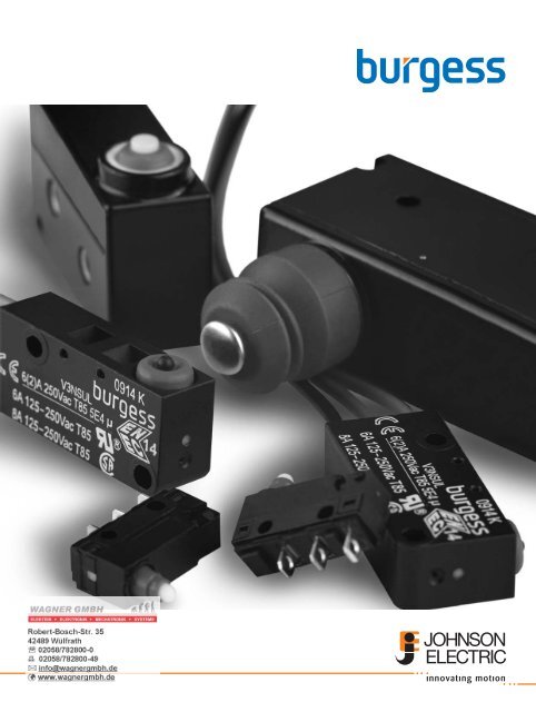
<strong>Burgess</strong> is the leading global brand for industrial switches<br />
<strong>Burgess</strong> designs have defined industry standards. If you need a specific solution<br />
for your switching needs, call us to set your own standard.<br />
A pioneer of snap-action technology, the <strong>Burgess</strong> brand<br />
stands for innovative, robust solutions for industrial<br />
switch requirements.<br />
Wide range<br />
Snap-action switches have to fulfill a wide variety of<br />
functions. The standard <strong>Burgess</strong> range ensures there<br />
will be a switch for your needs, with one of the broadest<br />
product portfolios around. From ultraminiature to<br />
metal-housed basic types, we are sure to have the type<br />
appropriate to your application, whether it is signal or<br />
power switching, high or low force actuation.<br />
Environmental protection<br />
The sealed switch is a <strong>Burgess</strong> speciality. In demanding<br />
environments – wet, humid or dusty – even the most<br />
sensitive signal can be switched<br />
reliably with IP67 rated products. Our robust<br />
metal-housed switches offer impact resistance<br />
outside whilst switching with precision inside.<br />
Uncompromising reliability<br />
With many UL, CSA and ENEC approvals, the performance<br />
of <strong>Burgess</strong> products is globally recognized. For<br />
safety-related applications, such as machine maintenance<br />
systems, positive-action mechanisms ensure a<br />
physical break in the circuit.<br />
Precision actuation<br />
Snap-action switches offer high levels of repeat accuracy<br />
and switch virtually independently of actuation<br />
speed and force. This is the mechanism of choice for<br />
pressure sensing, timing and position indicating applications.<br />
Minimum size<br />
Our F5 range demonstrates our capability to switch<br />
relatively high current from a small size envelope – 5A<br />
250 VAC from a switch less than<br />
13 mm long.<br />
Typical <strong>Burgess</strong> switch applications<br />
• Circuit breakers<br />
• Special purpose vehicles<br />
• Vending machines<br />
<strong>Burgess</strong> switches burgess-switch@johnsonelectric.om www.burgess-switch.com 5
<strong>Switch</strong>es in General Industry<br />
<strong>Switch</strong>es can be found in a wide variety of applications:<br />
<strong>Burgess</strong> switches for special<br />
purpose vehicles<br />
<strong>Switch</strong>es used in special purpose vehicle<br />
applications must have:<br />
• high levels of environmental protection<br />
• the ability to handle high DC inrush currents<br />
• reliability throughout the life of the product<br />
<strong>Burgess</strong> switches for vending<br />
machines<br />
<strong>Switch</strong>es used in vending machines must:<br />
• work reliably, time after time<br />
• have appropriate environmental protection to resist<br />
dust and moisture<br />
<strong>Switch</strong>es for locking mechanisms<br />
<strong>Switch</strong>es are found in numerous applications that require a<br />
locking device. Whether it is a medical application, an office<br />
automation application or a door lock, switches provide an<br />
effective, cost-efficient locking mechanism.<br />
<strong>Burgess</strong> switches for circuit breakers<br />
Circuit breaker applications demand:<br />
• dependability and reliability<br />
• a high degree of shock resistance in the<br />
mechanism<br />
• the ability to carry high currents and voltages<br />
Security Applications<br />
• Hotel room door lock<br />
• Hotel safe lock<br />
• Prison door lock<br />
• Fire safety door opening lock<br />
• Garage door safety lock<br />
Office Automation<br />
• Disk drive door lock<br />
• Personal computer<br />
chassis lock<br />
• Docking station lock<br />
• Locks to hold peripherals in<br />
place<br />
• Tape library index lock<br />
Medical<br />
• Sterilizer lock<br />
• Centrifuge lock<br />
• Blood analysis machine<br />
lock<br />
Industrial<br />
• Overhead door lock<br />
• Fire safety door lock<br />
• Commercial laundry locks<br />
6 <strong>Burgess</strong> switches www.burgess-switch.com<br />
burgess-switch@johnsonelectric.om
Terminology: Snap-action switches<br />
Positions – forces – movements<br />
Free position Position of the actuator, without any influence from an external force.<br />
Operating position Position of the actuator when contact changeover takes place.<br />
Total travel position Position of the actuator at the end of the allowed travel.<br />
Release position Position of the actuator when the switch mechanism resets.<br />
Actuating force The force required to move the actuator from the free position to the operating position.<br />
Release force The value to which the applied force must be reduced to allow the mechanism to<br />
reset after operation.<br />
Force differential Difference between actuating force and release force.<br />
Pre-travel Movement of the switch actuator between free and operating position.<br />
Over-travel Movement of the switch actuator beyond the operating position.<br />
Total travel The sum of pre-travel and over-travel.<br />
Movement differential Distance between operating position and release position.<br />
Release travel Movement of the switch actuator between release and total travel position.<br />
Post release travel Movement of the switch actuator between release and free position.<br />
Contact force – movement – diagram<br />
Actuator or<br />
auxiliary actuator<br />
Guide<br />
Pretravel<br />
Free position Operating Position Final position Release Force<br />
Operation of actuator or auxiliary actuator<br />
Overtravel<br />
<strong>Burgess</strong> switches burgess-switch@johnsonelectric.om www.burgess-switch.com 7<br />
Movement<br />
Differential<br />
Release Travel<br />
Post-release<br />
Travel<br />
Total Travel
Actuating force – movement – diagram<br />
Contact force – movement – diagram<br />
8 <strong>Burgess</strong> switches www.burgess-switch.com<br />
burgess-switch@johnsonelectric.om
<strong>Switch</strong> Technology<br />
Clearance Distance – the distance in air between current<br />
carrying parts of opposite polarity or between any current<br />
carrying part and an earthed-(grounded) metal plate to<br />
which the switch is attached.<br />
Creepage Distance – the path along the surface of<br />
insulating material between current carrying parts of<br />
opposite polarity or between any current carrying part and<br />
an earthed (grounded) metal plate to which the switch is<br />
attached.<br />
Insulation Resistance – resistance as measured between<br />
the normally closed terminals, or between all terminals<br />
connected together and a metal plate to which the switch<br />
is mounted. In dry conditions the value would be expected<br />
to be greater than 5Mh.<br />
Single Throw – a switch which provided an ON-OFF or<br />
OFF-ON function but does not change over from one<br />
conductor to another. Such switches are usually referred to<br />
as being «normally-closed only» or «normally-open only».<br />
<strong>Switch</strong>ing Cycle – one complete switching operating from<br />
free position into overtravel and back through release<br />
position to free position.<br />
<strong>Switch</strong> Resistance – a total resistance offered by a switch<br />
in a circuit, as measured from terminal through mating<br />
contacts, to terminal.<br />
Transit Time – the time taken by the moving contact in a<br />
snap-action mechanism to move from one stable position<br />
to another.<br />
<strong>Electric</strong>al Ratings<br />
<strong>Electric</strong>al ratings given in the catalog<br />
are ratings according to UL1054, CSA22.55 or<br />
IEC61058-1.<br />
Where these are not available, a general rating is given<br />
based upon in-house laboratory testing.<br />
The ratings tables should be considered as safe working<br />
maximums for most applications. How ever, switch<br />
performance is influenced by a variety of factors, including:<br />
▪ Frequency of operation<br />
▪ Type of load<br />
▪ Amount of travel used<br />
▪ Temperature<br />
▪ Humidity<br />
Please do not hesitate to contact <strong>Burgess</strong> about your<br />
specific application.<br />
Approvals<br />
CSA mark. <strong>Switch</strong> meets CSA’s safety standards<br />
UL Recognized Component Mark for Canada and the<br />
United States<br />
ENEC Mark. <strong>Switch</strong> fulfills European EN standards. The<br />
two digit number indicates which certification body has<br />
issued the ENEC Certificate<br />
<strong>Switch</strong> Life<br />
a. <strong>Electric</strong>al Life – the electrical life data contained in this<br />
catalog is based on laboratory controlled tests. In practice,<br />
frequency and speed of operation, type of load, suppression,<br />
actuator travel used, ambient humidity and temperature<br />
and other environmental conditions can have a major<br />
effect on switch life.<br />
Individual assessments for specific applications are<br />
possible and can be undertaken by <strong>Burgess</strong> on request.<br />
Please ask <strong>Burgess</strong> if you would like an assessment for<br />
your specific application.<br />
b. Mechanical Life – the figures quoted relate to the<br />
number of switching cycles made without an electrical<br />
load.<br />
<strong>Switch</strong> Drawings<br />
CQC Approval (China) is<br />
available for certain switches<br />
All drawings in this catalogue are third angle projection.<br />
All dimensions in this catalogue are nominal, except where<br />
specifically shown.<br />
<strong>Burgess</strong> switches burgess-switch@johnsonelectric.om www.burgess-switch.com 9
Application Technology<br />
Shock and Vibration<br />
If switches are likely to be subjected to shock or vibration,<br />
select models with the highest avail able actuating force.<br />
<strong>Burgess</strong> switches feature low mass mechanisms which are<br />
inherently resistant to shock and vibration.<br />
If possible, the switches should be mounted so that the line<br />
of acceleration is at right angles to the travel of the plunger.<br />
The maximum avail able overtravel should be used.<br />
Direct Current<br />
Direct current (DC) ratings where shown should not be<br />
exceeded if destructive arcing and contact welding are to<br />
be avoided.<br />
Some form of arc suppression is recommended when<br />
switches are used in DC circuits containing inductive<br />
devices wired in series with the switch and the supply.<br />
Lamp Loads<br />
Because of the very high inrush currents associated with<br />
incandescent lamps, applications should be subject to<br />
individual assessment.<br />
Capacitive Loads (including fluorescent lamps)<br />
These can generate very high peak currents which can<br />
cause contact welding. Applications should be subject to<br />
individual assessment.<br />
Inductive Loads<br />
The general ratings tables included in this catalog provide<br />
data for switches used to control inductive circuits at a<br />
power factor of 0.5 (EN 0.6; UL 0,7 means HP-Rating 0,5).<br />
Contact Materials<br />
Silver and silver alloys are the primary contact materials<br />
used in <strong>Burgess</strong> switches.<br />
The ratings tables shown refer to switches with silver/silver<br />
alloy contacts.<br />
Gold contacts should be specified when switches are to be<br />
used in low voltage control or logic circuits, especially when<br />
long periods of inactivity are expected or when atmospheres<br />
with a high sulphur content may be encountered.<br />
Gold contacts are generally available in two forms; gold<br />
plated silver alloy contacts, which can also be used at<br />
higher currents or gold alloy cross-point contacts, which<br />
are only suitable for switching low currents.<br />
Please ask <strong>Burgess</strong> if you would like an<br />
assessment for your specitic application.<br />
<strong>Switch</strong> Actuation<br />
Direct Operation<br />
Actuating plungers should be operated in the direction of<br />
their axis. Where this is not possible the use of actuating<br />
levers is recommended. For direct actuation the attack<br />
angle should not exceed 30°.<br />
Actuation by sliding cams.<br />
Actuating Levers<br />
Various lever types are available for use with <strong>Burgess</strong><br />
switches. They are generally stainless steel.<br />
If roller or cam-follower levers are approached in the<br />
reverse direction, care must be taken to ensure that the<br />
angle of approach is small enough not to jam the lever.<br />
Actuation by Cams<br />
Cam-follower levers are particularly well suited for use with<br />
plastic actuating cams.<br />
Abrupt actuation or release of switch actuators shortens<br />
the life of the switches.<br />
For this reason cam should preferably provide a continuous<br />
movement. Ideally they should be of cyclodal form.<br />
Long roller lever with continuous actuation<br />
10 <strong>Burgess</strong> switches www.burgess-switch.com<br />
burgess-switch@johnsonelectric.om
Environmental Protection<br />
Protection Classifications<br />
The protection classes of <strong>Burgess</strong> switches are in accordance<br />
with IEC 529 and are covered by just four codes.<br />
IP40<br />
Adequate protection against solids such as probing fingers<br />
and small wires>1mm. Liquids however can gain access<br />
and, unless externally protected, the switches should be<br />
mounted in dry or well-sheltered positions.<br />
IP5K4<br />
Good protection against solid foreign bodies, including<br />
dust and water splashing against the enclosure from any<br />
direction.<br />
<strong>Switch</strong>es may be used out of doors if sheltered from the<br />
worst of the elements or on factory machines subjected to<br />
normal washing down procedures.<br />
IP65<br />
Complete protection against solids, including dust, and<br />
against low pressure jets of water from all directions.<br />
IP6K7<br />
Complete protection against solids including dust and<br />
against immersion in water at a specific pressure for a<br />
specified time.<br />
We reserve this code for switches which are factory sealed<br />
and tested.<strong>Switch</strong>es should not be immersed in any liquid.<br />
*International IK code indicates protection against<br />
mechanical impact regarding to EN 50102.<br />
Working Temperatures<br />
For details of the working temperatures applicable to<br />
individual types, refer to the appropriate specification<br />
sheet. Special versions suitable for temperatures outside<br />
these ranges may be possible. Please contact us for<br />
information.<br />
All quoted temperatures assume stable operation. They<br />
do not imply an ability to withstand excessive cycling<br />
within the range.<br />
Health & Safety<br />
<strong>Burgess</strong> has ensured, so far as it is reasonably practicable,<br />
that their products are as described in this catalog or in<br />
other current company publications, or as specified on<br />
<strong>Burgess</strong><br />
installation drawings. They have been so design ed and<br />
constructed as to be safe and without risk to health when<br />
installed by suitably qualified personnel in accordance with<br />
relevant legislation, codes of practice, regulations (including<br />
IEE Wiring Regulations), the installation recommendations<br />
offered by the company and the accepted rules of the art.<br />
Their usage should be confined within the ratings limitations<br />
and parameters of-application indicated in this<br />
catalog and elsewhere.<br />
Please contact us should you need additional information<br />
or guidance.<br />
Service Recommendations<br />
Maintenance<br />
<strong>Burgess</strong> switches are not user-maintainable but they should<br />
be kept in a reasonably clean, paint-free condition,<br />
especially in the actuator area. Regular checks should be<br />
made on mounting security and on the actuating medium<br />
to switch actuator relationship.<br />
Lubrication or the use of aqueous or chemical cleaning<br />
fluids is not recommended.<br />
Installation Recommendations<br />
The following notes are intended merely to stress the most<br />
important and general aspects of good switch installation<br />
procedure and to provide some helpful additional information.<br />
Safety Consideration<br />
Installation should only be carried out by competent<br />
personnel.<br />
<strong>Switch</strong> Positioning and Operation<br />
Pre-loading of the switch actuator must be avoid ed. The<br />
actuating medium must be able to operate the switch<br />
through the operating position into overtravel and then to<br />
retract far enough to allow the switch to regain its free<br />
position.<br />
<strong>Burgess</strong> recommends that the actuating medium should<br />
drive the switch into at least 50% of the available overtravel.<br />
All ratings tables shown in this catalog are based on the<br />
use of all the available overtravel.<br />
<strong>Burgess</strong> switches burgess-switch@johnsonelectric.om www.burgess-switch.com 11
Mounting<br />
Side mounting switches should be mounted on smooth,<br />
firm, flat surfaces using the recommended screw size.<br />
Avoid over tightening the screws. For added security, they<br />
should be locked using epoxy resin. Do not attempt to<br />
enlarge switch mounting holes and avoid over stressing the<br />
switch. Use insulating material between the switch and<br />
metallic plates to increase clearance on switches with open<br />
terminals.<br />
Connections<br />
When soldering, overheating of the switch insulation must<br />
be avoided. In certain circumstances, it may be advisable<br />
to use a heat shunt. For optimum mechanical strength, the<br />
conductor should be wrapped round the tip of the terminal<br />
taking care to avoid loose strands of wire.<br />
The soldering iron tip should be applied to the end of the<br />
terminal while simultaneously ap plying solder. Remove the<br />
iron as soon as the solder has wetted the conductor and<br />
terminal end. A-soldering iron tip temperature of 350°C<br />
(260°C/5 seconds for PCB Terminals) applied for a<br />
maximum of 2-3 seconds should be adequate.<br />
For lead-free solder, is usually needed an iron tip<br />
temperature 15% higher.<br />
Installation Recommendations (EN 61058-1)<br />
Mounting Holes and Screw sizes Mounting Screw Torque<br />
Normal hole Diameter Metric Unified For guidance when using<br />
Thread<br />
(mm) (in) Screw Screw mild steel screws:<br />
2.2/2.3 0.067/0.091 M2 #2 M2 or #2 screws 0.15Nm<br />
3.1/3.2 0.122/0.126 M3 #4 M3 or #4 screws 0.5Nm<br />
3.6/3.7 0.142/0.146 M3.5 #6 M3.5 or #6 screws 0.8Nm<br />
5.1/5.2 0.201/0.205 M5 #10 M5 or #10 screws 3.0Nm<br />
12 <strong>Burgess</strong> switches www.burgess-switch.com<br />
burgess-switch@johnsonelectric.om
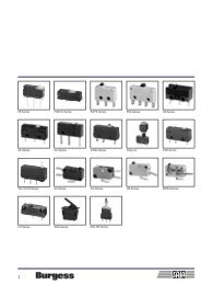
Type<br />
Characteristics<br />
Rating<br />
Dimensions (mm)<br />
Actuator<br />
Approvals<br />
Page<br />
Type<br />
Characteristics<br />
Rating<br />
Dimensions (mm)<br />
Actuator<br />
Approvals<br />
Page<br />
Snap-action Microswitches<br />
■ double break switching<br />
■ long mechanical and<br />
electrical life<br />
■ solder<br />
250 VAC, 5 A<br />
18 • 8 • 5<br />
■ plunger<br />
■ plain lever<br />
■ simulated roller lever/<br />
cam follower<br />
UL, CSA<br />
31<br />
Ultraminiature<br />
F1 F4 F5 F1NS L16<br />
◼ small size<br />
■ high current<br />
■ long mechanical<br />
and electrical life<br />
■ PCB mounting<br />
250 VAC, 5 A<br />
16 • 6 • 6.5<br />
■ plunger<br />
■ plain lever<br />
■ simulated roller lever/<br />
cam follower<br />
UL, CSA<br />
16<br />
■ small size<br />
■ long mechanical and<br />
electrical life<br />
■ solder terminals<br />
■ solder terminals<br />
250 VAC, 5 A<br />
12.8 • 10 • 5<br />
■ plunger<br />
■ plain lever<br />
■ simulated roller lever/<br />
cam follower<br />
UL, CSA<br />
19<br />
Subminiature Miniature sealed<br />
FK4 V4L V3NS V3S<br />
■ long overtravel of<br />
2.2 mm minimum<br />
■ sealed to IP6K7 option<br />
■ pre-wired option<br />
■ solder terminals<br />
■ compliant to glow wire<br />
test IEC 60335-1, 4.<br />
ed. as optional item<br />
250 VAC, 5 A<br />
20 • 11 • 6.4<br />
■ plunger<br />
■ plain lever<br />
■ ice break lever<br />
ENEC, UL, CSA<br />
35<br />
■ small size<br />
■ long mechanical<br />
and electrical life<br />
■ PCB mounting<br />
250 VAC, 5 A<br />
12.8 • 7 • 5<br />
■ plunger<br />
■ plain lever<br />
■ simulated roller lever/<br />
cam follower<br />
UL, CSA<br />
22<br />
■ sealed (IP67)<br />
■ pre-wired option<br />
■ faston terminals<br />
■ robust construction<br />
■ compliant to glow<br />
wire requirements<br />
IEC 60335<br />
250 VAC, 6 A<br />
33 • 10.4 • 15.9<br />
■ plunger<br />
■ plain lever<br />
■ roller lever<br />
■ cam follower lever<br />
UL, CSA, ENEC<br />
40<br />
■ small size<br />
■ PCB mounting<br />
■ sealed IP54 (option)<br />
up to 250 VAC, 1 A<br />
14.6 • 6.5 • 6<br />
■ plunger<br />
■ plain lever<br />
■ simulated roller lever/<br />
cam follower<br />
■ small size<br />
■ sealed (IP6K7)<br />
■ PCB mounting<br />
12–30 VDC, 1–300 mA<br />
14.7 • 9 • 5.4<br />
■ plunger<br />
■ plain lever<br />
■ cam follower<br />
Automotive standard<br />
<strong>Burgess</strong> switches burgess-switch@johnsonelectric.om www.burgess-switch.com 13<br />
none<br />
25<br />
■ sealed (IP67)<br />
■ pre-wired<br />
■ robust construction<br />
250 VAC, 5 A<br />
32 • 24 • 10<br />
■ plunger<br />
■ plain lever<br />
■ roller lever<br />
UL, CSA, ENEC<br />
43<br />
28
Type<br />
Characteristics<br />
Rating<br />
Dimensions (mm)<br />
Actuator<br />
Approvals<br />
Page<br />
Type<br />
Characteristics<br />
Rating<br />
Dimensions (mm)<br />
Actuator<br />
Approvals<br />
Page<br />
Snap-action Microswitches<br />
3BR V9N 4BR<br />
■ choice of IP54 or IP67<br />
sealed versions<br />
■ precise movements<br />
■ screw terminals<br />
■ pre-wired option<br />
■ long overtravel<br />
250 VAC, 10 A max.<br />
53.1 • 20.6 • 30.8<br />
■ plunger<br />
UL, CSA<br />
52<br />
Standard Metal housed<br />
■ sealed (IP67)<br />
■ metal housed<br />
■ screw terminals<br />
■ pre-wired option<br />
250 VAC, 10 A max.<br />
42 • 24.5 • 16<br />
■ plunger<br />
■ plain levers<br />
■ reverse action levers<br />
■ roller levers<br />
UL, CSA<br />
55<br />
■ choice of IP54 or<br />
IP67 sealed versions<br />
■ precise movements<br />
■ metal housing<br />
■ pre-wired option<br />
■ long overtravel<br />
125 VAC, 10 A max.<br />
53.1 • 20.6 • 29.2<br />
■ plunger<br />
UL, CSA<br />
Miniature Standard Forced break<br />
BVM3 KB5 XP XT<br />
■ positive-action forced<br />
break switching<br />
■ > 3 mm contact gap at<br />
full travel<br />
■ internationally<br />
recognized V3 housing<br />
■ faston terminals<br />
250 VAC, 10 A<br />
28 • 16 • 10.5<br />
■ plunger<br />
■ plain lever<br />
■ roller lever<br />
ULS, CSA, ENEC<br />
63<br />
■ positive-action forced<br />
double break switching<br />
■ > 3 mm contact gap at<br />
full travel<br />
■ high electrical rating<br />
■ faston terminals<br />
up to 250 V, 25 A<br />
41 • 19.5 • 15.5<br />
■ plunger<br />
■ plain lever<br />
■ roller lever<br />
ULS, CSA<br />
66<br />
59<br />
■ double break switching<br />
■ positive-action force<br />
break option<br />
■ > 3 mm contact gap at<br />
full travel option<br />
■ faston terminals<br />
400 VAC, 16 A<br />
30 • 32 • 12<br />
■ plain plunger<br />
■ mushroom plunger<br />
■ plunger with external<br />
spring (for increased<br />
reset security)<br />
UL, CSA, ENEC<br />
70<br />
■ 8 mm contact gap<br />
8 mm creepage and<br />
clearance distances<br />
■ double break contacts<br />
400 VAC, 16.5 A max.<br />
30 • 32 • 12<br />
■ shrouded plunger<br />
■ optional key<br />
■ plain plunger<br />
UL, cUL, CSA, ENEC<br />
14 <strong>Burgess</strong> switches www.burgess-switch.com<br />
burgess-switch@johnsonelectric.om<br />
73
Coil spring mechanism<br />
Microswitch<br />
Locknut Dimensions mounting<br />
<strong>Burgess</strong> switches burgess-switch@johnsonelectric.om<br />
www.burgess-switch.com<br />
Ø 2.60<br />
[0.1]<br />
Ø 1.8 ± 0.05<br />
[0.07]<br />
5.7<br />
[0.22]<br />
MAX<br />
5.1<br />
[0.2]<br />
3 EQUI-SPACED RIBS<br />
R0.1 [0.04]<br />
[0.19]<br />
3°<br />
ENLARGED VIEW OF PEG<br />
4.85<br />
3.1<br />
[0.12]<br />
0.50<br />
[0.02]<br />
FREE<br />
POSITION<br />
OPERATING<br />
Ø 2.0 ± 0.05<br />
[0.08]<br />
6.5<br />
MAX<br />
[0.26]<br />
1.1<br />
Circuit diagram<br />
[0.04]<br />
2.9<br />
[0.11]<br />
POSITION<br />
2.54<br />
[0.1]<br />
1.35<br />
[0.05]<br />
2.03<br />
[0.08]<br />
4.0<br />
[0.16]<br />
4.15 1.40<br />
[0.16]<br />
[0.06]<br />
8.60 1.25<br />
[0.34]<br />
[0.05]<br />
16.0<br />
MAX<br />
[0.63]<br />
2.3<br />
[0.09]<br />
2.0<br />
[0.08]<br />
8.6<br />
[0.34] [0.2]<br />
F1T8GPUL 1.5X FULL SIZE<br />
1.50<br />
0.50<br />
[0.02]<br />
MAX
Ultraminiature<br />
F1<br />
F1<br />
Characteristics ■ small size<br />
■ high current<br />
■ long mechanical and electrical life<br />
■ PCB mounting<br />
Rating 250 VAC, 5 A<br />
Dimensions (mm) 16 × 6 × 6,5<br />
Actuator ■ plunger<br />
■ plain lever<br />
■ simulated roller lever/cam follower<br />
Approvals UL, CSA<br />
Preferred Range<br />
Ordering Actuating Force Sealing Operating pos, Terminal Circuit Actuator Contacts <strong>Electric</strong>al rating<br />
Reference (N) (ozf) (mm) (in)<br />
F1T8GPUL 1,4 5,00 IP40 6,35 0,25 PCB CO Plunger Gold plate Up to 250 VAC, 5 A<br />
F1T8Y1GPUL 0,5 1,8 IP40 8,5 0,33 PCB CO Lever Gold plate Up to 250 VAC, 5 A<br />
Circuit diagram<br />
Specifications<br />
Housing Glass fibre reinforced flame retardant nylon<br />
Plunger Nylon<br />
Mechanism Snap-action, coil spring mechanism with stainless steel spring<br />
Functions Single pole change-over<br />
Contacts Gold plate on silver<br />
Terminals PCB - copper, gold-flashed<br />
Temperature range ºC –40°C to +85°C<br />
Mechanical life 10 6 cycles minimum (impact-free actuation)<br />
Protection IP40 (enclosure)<br />
Mounting Side mount PCB with locating pin on housing<br />
Actuators Plain plunger, stainless steel<br />
16 <strong>Burgess</strong> switches burgess-switch@johnsonelectric.om<br />
www.burgess-switch.com
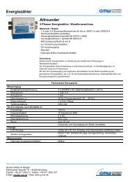
Dimensions<br />
F1<br />
Ø 2.60<br />
[0.1]<br />
Ø 1.8 ± 0.05<br />
[0.07]<br />
5.7<br />
[0.22]<br />
MAX<br />
5.1<br />
[0.2]<br />
3 EQUI-SPACED RIBS<br />
R0.1 [0.04]<br />
4.85<br />
[0.19]<br />
3°<br />
ENLARGED VIEW OF PEG<br />
3.1<br />
[0.12]<br />
0.50<br />
[0.02]<br />
FREE<br />
POSITION<br />
OPERATING<br />
Ø 2.0 ± 0.05<br />
[0.08]<br />
2.9<br />
[0.11]<br />
6.5<br />
MAX<br />
[0.26]<br />
1.1<br />
[0.04]<br />
POSITION<br />
2.54<br />
[0.1]<br />
1.35<br />
[0.05]<br />
2.03<br />
[0.08]<br />
4.0<br />
[0.16]<br />
4.15 1.40<br />
[0.16]<br />
[0.06]<br />
8.60 1.25<br />
[0.34]<br />
[0.05]<br />
16.0<br />
MAX<br />
[0.63]<br />
2.3<br />
[0.09]<br />
8.6<br />
[0.34] [0.2]<br />
F1T8GPUL 1.5X FULL SIZE<br />
<strong>Burgess</strong> switches burgess-switch@johnsonelectric.om<br />
www.burgess-switch.com<br />
2.0<br />
[0.08]<br />
1.50<br />
0.50<br />
[0.02]<br />
MAX<br />
Recommended maximum electrical ratings<br />
Voltage Resistive load Inductive load Approval<br />
(max) (A)<br />
Ø 2.60<br />
[0.1]<br />
Ø 1.8 ± 0.05<br />
[0.07]<br />
5.7<br />
MAX<br />
[0.22]<br />
Ø 2.0 ± 0.05<br />
[0.08]<br />
4.05<br />
[0.16]<br />
3°<br />
ENLARGED VIEW OF PEG<br />
3 EQUI-SPACED RIBS<br />
R0.1 [0.04]<br />
[0.02]<br />
FREE POSITION<br />
OPERATING<br />
POSITION<br />
250 VAC 5 (0.75 pf) 5 UL 1054/CSA 22.2 No. 55 - 6,000 operations<br />
0 - 15 VDC 5 General rating - 50,000 operations<br />
15 - 30 VDC 3 General rating - 50,000 operations<br />
Operating Characteristics<br />
0.50<br />
2.9<br />
6.5<br />
MAX<br />
[0.26]<br />
[0.11]<br />
1.1<br />
[0.04]<br />
2.54<br />
[0.1]<br />
1.35<br />
[0.05]<br />
8.60 1.25<br />
[0.34]<br />
[0.05]<br />
17.93<br />
[0.71]<br />
4.15 1.40<br />
[0.16]<br />
[0.06]<br />
4.62<br />
[0.18]<br />
2.0<br />
[0.08]<br />
1.50<br />
8.6<br />
[0.34]<br />
16.0<br />
[0.63]<br />
MAX<br />
F1T8Y1GPUL 1.5X FULL SIZE<br />
Actuating Release Free Operating Movement Over<br />
Actuator Reference Force Force Position Position Differential Travel<br />
Maximum Minimum Maximum Maximum<br />
(N) (ozf) (N) (ozf) (mm) (in) (mm) (in) (mm) (in) (mm) (in)<br />
Plunger F1T8GPUL 1,4 5,00 0,28 1,00 7,1 0,28 6,35 ± 0.38 0,25 ± 0.015 0,1 0,004 *<br />
Straight lever F1T8Y1GPUL 0,5 1,8 0,06 0,022 11,0 0,43 8,5 ± 1,5 0,33 ± 0.06 0,5 0,02 *<br />
1 4<br />
1<br />
2<br />
4 1<br />
4<br />
1<br />
2<br />
17.93<br />
[0.71]<br />
Width of lever 4.05 mm/0.16 in<br />
2<br />
17.93<br />
[0.71]<br />
* Plunger can be depressed flush with housing. The housing should not be used as an end stop.<br />
0.50<br />
[0.02]<br />
MAX<br />
4.1<br />
[0.16]<br />
[0.06]<br />
17<br />
Ultraminiature
Ultraminiature<br />
Basic type F1<br />
F1<br />
Ordering Reference<br />
Terminals T8 PCB 1,25 • 0,5 • 2,9 long<br />
Actuators No symbol, without lever<br />
Y1 Plain lever 21.0 mm<br />
YR1 Roller lever 16.0 mm<br />
Contacts Material No symbol, Ag<br />
GP Gold plate on Ag (GP)<br />
Approvals UL UL and CSA approval<br />
Special Features /□□□□ <strong>Burgess</strong> specialise in customer specific solutions.<br />
Additional product variants are available or can be provided.<br />
If your requirements cannot be satisfied from the options listed,<br />
please contact us.<br />
Example: F1 T8 Y1 GP UL<br />
18 <strong>Burgess</strong> switches burgess-switch@johnsonelectric.om<br />
www.burgess-switch.com
F4<br />
F4<br />
Characteristics ■ small size<br />
■ long mechanical and electrical life<br />
■ solder terminals<br />
Rating 250 VAC, 5 A<br />
Dimensions (mm) 12.8 × 10 • 5<br />
Actuator ■ plunger<br />
■ plain lever<br />
■ simulated roller lever/cam follower<br />
Approvals UL, CSA<br />
Preferred Range<br />
Ordering Actuating Force Sealing Operating pos. Terminal Circuit Actuator Contacts <strong>Electric</strong>al rating<br />
Reference (N) (ozf) (mm) (in)<br />
F4T7UL 1.4 5.00 IP40 8.1 0.32 Solder CO Plunger Ag Up to 250 VAC, 5 A<br />
F4T7GPUL 1.4 5.00 IP40 8.1 0.32 Solder CO Plunger Gold plate Up to 250 VAC, 5 A<br />
F4T7Y1UL 0.6 2.20 IP40 8.2 0.32 Solder CO Plain lever Ag Up to 250 VAC, 5 A<br />
F4T7Y1GPUL 0.6 2.20 IP40 8.2 0.32 Solder CO Plain lever Gold plate Up to 250 VAC, 5 A<br />
F4T7YCUL 0.7 2.50 IP40 10.3 0.41 Solder CO Simulated roller Ag Up to 250 VAC, 5 A<br />
F4T7YCGPUL 0.7 2.50 IP40 10.3 0.41 Solder CO Simulated roller Gold plate Up to 250 VAC, 5 A<br />
<strong>Burgess</strong> switches burgess-switch@johnsonelectric.om<br />
www.burgess-switch.com<br />
19<br />
Ultraminiature
Ultraminiature<br />
Circuit diagram<br />
Dimensions<br />
F4<br />
Specifications<br />
Housing Glass fibre reinforced flame retardent nylon<br />
Plunger Nylon<br />
Mechanism Snap-action, single pole<br />
Functions Change-over, Normally open, Normally closed<br />
Contacts Fixed, Moving – Ag or Gold plate on Ag<br />
Terminals 2.0 mm (0.08 in) faston and solder - brass, gold flashed<br />
Temperature range ºC -40°C to +85°C<br />
Mechanical life 10 7 cycles minimum (impact free actuation)<br />
Protection IP 40 (enclosure)<br />
Mounting Side mounting<br />
Actuators Plain lever, simulated roller lever/cam follower, stainless steel<br />
Accessories Lug mounting frame, insulating sheet, spring-leaf actuator<br />
COMMON<br />
Free position<br />
1<br />
F4T7<br />
OP<br />
Mounting holes<br />
Recommended maximum electrical ratings<br />
Voltage Load Approval<br />
(max) (A)<br />
2<br />
4<br />
NORMALLY<br />
CLOSED<br />
NORMALLY<br />
OPEN<br />
250 VAC 5 (0.75 pf) UL 1054/CSA 22.2 No. 55 - 6,000 operations<br />
125 VAC 5 (0.75 pf) UL 1054/CSA 22.2 No. 55 - 6,000 operations<br />
0 - 15 VDC 5 General rating - 50,000 operations<br />
15 - 30 VDC 3 General rating - 50,000 operations<br />
20 <strong>Burgess</strong> switches burgess-switch@johnsonelectric.om<br />
www.burgess-switch.com
Plunger<br />
Y1-Lever<br />
YC-Lever<br />
Basic type F4<br />
F4<br />
Operating Characteristics<br />
Actuating Release Free Operating Movement Over<br />
Actuator Reference Force Force Position Position Differential travel<br />
Maximum Minimum Maximum Maximum<br />
(N) (ozf) (N) (ozf) (mm) (in) (mm) (in) (mm) (in)<br />
F4T7<br />
F4T7Y1<br />
Width of lever 3.0 mm/0.12 in<br />
F4T7YC<br />
Width of lever 3.0 mm/0.12 in<br />
1,4 5,00 0,25 0,90 8,8 0,35 8,1 +0.3 0,32 +0.01<br />
–0.2 –0.008<br />
0,6 2,20 0,07 0,25 10,0 0,39 8,2 +1.0<br />
0,32 +0.04<br />
–0.7 –0.03<br />
0,7 2,50 0,09 0,32 11,7 0,46 10,3 +0.8 0,41 +0.03<br />
–0.55 –0.02<br />
Operating characteristics are specified from the mounting holes.<br />
* Plunger can be depressed flush with housing. The hous ing should not be used as an end stop.<br />
Ordering Reference<br />
Terminals T7 Solder 3.50 • 0.5 • 3.6 long<br />
Circuit No symbol, change-over<br />
Actuators No symbol, without lever<br />
Y1 Plain lever 21.0 mm<br />
YC Cam follower lever 16.9 mm<br />
Contacts Material No symbol, Ag<br />
GP Gold plate on Ag (GP)<br />
Approvals No symbol, without approval<br />
UL UL and CSA approval<br />
Special Features /□□□□ <strong>Burgess</strong> specialise in customer specific solutions.<br />
Additional product variants are available or can be provided.<br />
If your requirements cannot be satisfied from the options listed,<br />
please contact us.<br />
0,13 0,005 *<br />
0,70 0,030 *<br />
0,45 0,020 *<br />
Example: F4 T7 Y1 GP UL<br />
<strong>Burgess</strong> switches burgess-switch@johnsonelectric.om<br />
www.burgess-switch.com<br />
21<br />
Ultraminiature
Ultraminiature<br />
F5<br />
F5<br />
Characteristics ■ small size<br />
■ long mechanical and electrical life<br />
■ PCB mounting<br />
Rating 250 VAC, 5 A<br />
Dimensions (mm) 12.8 • 7 • 5<br />
Actuator ■ plunger<br />
■ plain lever<br />
■ simulated roller lever/cam follower<br />
Approvals UL, CSA<br />
Preferred Range<br />
Ordering Actuating Force Sealing Operating pos. Terminal Circuit Actuator Contacts <strong>Electric</strong>al rating<br />
Reference (N) (ozf) (mm) (in)<br />
F5T8UL 1.4 5.00 IP40 8.75 0.34 PCB CO Plunger Ag Up to 250 VAC, 5 A<br />
F5T8GPUL 1.4 5.00 IP40 8.75 0.34 PCB CO Plunger Gold plate Up to 250 VAC, 5 A<br />
F5T8Y1UL 0.6 2.20 IP40 8.80 0.35 PCB CO Plain lever Ag Up to 250 VAC, 5 A<br />
F5T8Y1GPUL 0.6 2.20 IP40 8.80 0.35 PCB CO Plain lever Gold plate Up to 250 VAC, 5 A<br />
F5T8YCUL 0.7 2.50 IP40 10.90 0.43 PCB CO Simulated roller Ag Up to 250 VAC, 5 A<br />
F5T8YCGPUL 0.7 2.50 IP40 10.90 0.43 PCB CO Simulated roller Gold plate Up to 250 VAC, 5 A<br />
22 <strong>Burgess</strong> switches burgess-switch@johnsonelectric.om<br />
www.burgess-switch.com
Circuit diagram<br />
Dimensions<br />
F5<br />
Specifications<br />
Housing Glass fibre reinforced flame retardent nylon<br />
Plunger Nylon<br />
Mechanism Snap-action, single pole<br />
Functions Change-over, Normally open, Normally closed<br />
Contacts Fixed, Moving - Silver or Gold plate on silver<br />
Terminals PCB - Brass, gold flashed<br />
Temperature range ºC -40°C to +85°C<br />
Mechanical life 10 7 cycles minimum (impact free actuation)<br />
Protection IP 40 (enclosure)<br />
Mounting PCB<br />
Actuators Plain lever, simulated roller lever/cam follower, stainless steel<br />
COMMON<br />
1<br />
2<br />
4<br />
NORMALLY<br />
CLOSED<br />
NORMALLY<br />
OPEN<br />
Recommended maximum electrical ratings<br />
Voltage Load Approval<br />
(max) (A)<br />
250 VAC 5 (0.75 pf) UL 1054/CSA 22.2 No. 55 - 6,000 operations<br />
125 VAC 5 (0.75 pf) UL 1054/CSA 22.2 No. 55 - 6,000 operations<br />
0 - 15 VDC 5 General rating - 50,000 operations<br />
15 - 30 VDC 1 General rating - 50,000 operations<br />
<strong>Burgess</strong> switches burgess-switch@johnsonelectric.om<br />
www.burgess-switch.com<br />
23<br />
Ultraminiature
Ultraminiature<br />
F5<br />
Operating Characteristics<br />
Actuating Release Free Operating Movement Over<br />
Actuator Reference Force Force Position Position Differential travel<br />
Maximum Minimum Maximum Maximum<br />
(N) (ozf) (N) (ozf) (mm) (in) (mm) (in) (mm) (in)<br />
Plunger F5T8 1,4 5,00 0,25 0,90 9.5 0,37 8,75 ± 0,3 0,34 ± 0,012 0,13 0,005 *<br />
Y1-Lever F5T8Y1 0,6 2,20 0,07 0,25 10,7 0,42 8,8 ± 1,1 0,35 ± 0,04 0,70 0,030 *<br />
Width of lever 3.0 mm/0.12 in<br />
YC-Lever F5T8YC 0,7 2,50 0,09 0,32 12.4 0,49 10,9 ± 0.85 0,43 ± 0,03 0,45 0,020 *<br />
Basic type F5<br />
Width of lever 3.0 mm/0.12 in<br />
Operating characteristics are specified from the terminal shoulder.<br />
* Plunger can be depressed flush with housing. The hous ing should not be used as an end stop.<br />
Ordering Reference<br />
Terminals T8 PCB 1.27 • 0.5 • 3.0 long<br />
Circuit No symbol, change-over<br />
Actuators No symbol, without lever<br />
Y1 Plain lever 21.0 mm<br />
YC Cam follower lever 16.9 mm<br />
Contact Material No symbol, Ag<br />
GP Gold plate on Ag (GP)<br />
Approvals No symbol, without approval<br />
UL UL and CSA approval<br />
Special Features /□□□□ <strong>Burgess</strong> specialise in customer specific solutions.<br />
Additional product variants are available or can be provided.<br />
If your requirements cannot be satisfied from the options listed,<br />
please contact us.<br />
Example: F5 T8 Y1 GP UL<br />
24 <strong>Burgess</strong> switches burgess-switch@johnsonelectric.om<br />
www.burgess-switch.com
F1NS<br />
Characteristics ◼ small size<br />
■ low current<br />
■ long mechanical life<br />
■ PCB mounting<br />
■ sealed IP54 (option)<br />
Rating Up to 250 VAC, 1 A<br />
Dimensions (mm) 14.6 • 6.5 • 6<br />
Actuator ■ plunger<br />
■ plain lever<br />
■ simulated roller lever/cam follower<br />
Approvals none<br />
F1NS<br />
Preferred Range<br />
Ordering Actuating Force Sealing Operating pos. Terminal Circuit Actuator Contacts <strong>Electric</strong>al rating<br />
Reference (N) (ozf) (mm)<br />
F1NST8 2,0 7,2 IP5K4 5,9 PCB CO Plunger Ag 250 VAC, 1 A<br />
F1NST8A1 0,6 2,2 IP5K4 7,6 PCB CO Plain lever Ag 250 VAC, 1 A<br />
F1NST8AC 0,6 2,2 IP5K4 10,1 PCB CO Cam follower Ag 250 VAC, 1 A<br />
<strong>Burgess</strong> switches burgess-switch@johnsonelectric.om<br />
www.burgess-switch.com<br />
25<br />
Ultraminiature
Ultraminiature<br />
Circuit diagram<br />
Dimensions<br />
F1NS<br />
Specifications<br />
Housing Base: PA 6.6; Cowl: Silicon; Lid: PA 6.6<br />
Plunger POM<br />
Mechanism Snap-action, coil spring mechanism with stainless steel spring. Single-pole change-over contact<br />
Contacts Fine silver, Gold plate on silver<br />
Terminals PCB - Phosphor Bronze silver plated<br />
Temperature range ºC –40°C bis +85°C<br />
Mechanical life 10 7 cycles minimum (impact-free actuation)<br />
Protection Enclosure IP40 (F1N), IP54 (F1NS)<br />
Mounting PCB. Locating pins on housing<br />
COMMON<br />
NORMALLY<br />
CLOSED<br />
NORMALLY<br />
OPEN<br />
2.8<br />
±0.15<br />
14,6 MAX<br />
(.58)<br />
Recommended maximum electrical ratings<br />
Voltage Resistive load Inductive load Voltage Resistive load Inductive load<br />
(VAC) (A) (A) (VDC) (A) (A)<br />
125 1 1 up to<br />
250 1 1 30 2 2<br />
50 0,5 0,5<br />
75 0,25 0,25<br />
125 0,2 0,03<br />
4.8<br />
26 <strong>Burgess</strong> switches burgess-switch@johnsonelectric.om<br />
www.burgess-switch.com
Operating Characteristics<br />
Actuating Release Free Operating Movement Total travelled<br />
Actuator Reference Force Force Position Position Differential position<br />
Maximum Minimum Maximum Maximum Maximum<br />
(N) (ozf) (N) (ozf) (mm) (in) (mm) (in) (mm) (in) (mm) (in)<br />
Plunger F1NST8 2 7,20 0,2 0,72 6,5 0,26 5,9 ± 0,2 0,23 ± 0,008 0,2 0,008 *<br />
A1-Lever F1NST8A1 0,6 2,20 0,09 0,32 10,5 0,41 7,6 ± 1,2 0,3 ± 0,05 0,7 0,03 *<br />
Width of lever 3 mm/0,12 in<br />
AC-Lever F1NST8AC 0,6 2,20 0,09 0,32 13,3 0,52 10,1 ± 1,2 0,4 ± 0,05 0,7 0,03 *<br />
Basic type F1N<br />
F1NS<br />
Width of lever 3 mm/0,12 in<br />
Datum for Free Position and Operating Position: base of switch opposite plunger.<br />
* Flush with case. The case should not be used as an end stop.<br />
Ordering Reference<br />
Type of sealing No symbol, unsealed<br />
S Sealed IP5K4<br />
Terminals T8 PCB 0.8 • 0.5 • 3.45 long<br />
Circuit No symbol, change-over<br />
Actuators No symbol, without lever<br />
A Special lever A type (see specification)<br />
A1 Plain lever 18.0 mm<br />
AC Cam follower lever 18.5 mm<br />
Contact Material No symbol, Ag<br />
AU Gold on nickel<br />
GP Gold plate on Ag (GP)<br />
Special Features /□□□□ <strong>Burgess</strong> specialise in customer specific solutions.<br />
Additional product variants are available or can be provided.<br />
If your requirements cannot be satisfied from the options listed,<br />
please contact us.<br />
Example: F1N S T8 A AU<br />
<strong>Burgess</strong> switches burgess-switch@johnsonelectric.om<br />
www.burgess-switch.com<br />
27<br />
Ultraminiature
Ultraminiature<br />
L16<br />
L16<br />
Characteristics ■ small size<br />
■ sealed (IP6K7)<br />
■ PCB mounting<br />
Rating 12–30 VDC, 1–300 mA<br />
Dimensions (mm) 14.7 • 9 • 5.4<br />
Actuator ■ plunger<br />
■ plain lever<br />
■ cam follow lever<br />
Approvals Automotive standard<br />
Preferred Range<br />
Ordering Actuating Force Sealing Operating pos. Terminal Circuit Actuator Contacts <strong>Electric</strong>al rating<br />
Reference (N) (mm)<br />
L16T85 1,6 IP6K7 10,9 PCB CO Plunger Gold plated 30 VDC, 300 mA<br />
28 <strong>Burgess</strong> switches burgess-switch@johnsonelectric.om<br />
www.burgess-switch.com
Circuit diagram<br />
Dimensions<br />
L16<br />
Specifications<br />
Base PBT<br />
Lid PP6 with glass fibre<br />
Plunger POM<br />
Mechanism Snap-action, single pole<br />
Contacts Gold plated<br />
Terminals CuZn silver plated<br />
Temperature range ºC -40°C up to +85°C<br />
Mechanical life 1 • 10 6<br />
Protection IP67<br />
Actuators Plain plunger, lever, cam follower stainless steel<br />
Cowl Thermoplastic elastomer<br />
a d b<br />
CO NO NC<br />
Recommended maximum electrical ratings<br />
Voltage Resistive load Cycles<br />
(VDC) (A)<br />
L16 12 to 30 0,001 – 0,3 200.000<br />
<strong>Burgess</strong> switches burgess-switch@johnsonelectric.om<br />
www.burgess-switch.com<br />
29<br />
Ultraminiature
Ultraminiature<br />
Operating Characteristics<br />
Actuating Release Free Operating Movement Total travelled<br />
Actuator Reference Force Force Position Position Differential positions<br />
Maximum Minimum Maximum Maximum Minimum<br />
(N) (N) (mm) (mm) (mm) (mm)<br />
Plunger F6T85 1,6 0,2 11.5 10.95 ± 0.25 0,3 9.6<br />
H-Lever F6T85H For positions and forces of this actuator please contact Saia <strong>Burgess</strong><br />
Basic type F6<br />
L16<br />
Width of lever 3.0 mm/0.12 in<br />
2,5 0,5 13,00 11,4 + 0,55 0,45 10.1<br />
Datum for free position and operating position is button edge of base (stand-off’s).<br />
The case should not be used as an end stop.<br />
Ordering Reference<br />
Terminals T8 PCB 0.6 • 0.5 • 4.0 long<br />
T81 Formed PCB 0.6 • 0.5 • 2.35 long (Side mount L.H. plunger end)<br />
T82 Formed PCB 0.6 • 0.5 • 2.85 long (Side mount R.H. plunger end)<br />
T84 Short PCB 0.6 • 0.5 • 2.0 long<br />
T85 Long PCB 0.6 • 0.5 • 6.85 long<br />
Circuit No symbol, change-over<br />
Actuators No symbol, without lever<br />
H Formed. lever 0.3 mm thickness<br />
Y1 Plain lever 21 mm<br />
YC Cam follower lever 16.9 mm<br />
HC Cam follower<br />
Contact Material No symbol, Ag, gold plated<br />
Special Features /□□□□ <strong>Burgess</strong> specialise in customer specific solutions.<br />
Additional product variants are available or can be provided.<br />
If your requirements cannot be satisfied from the options listed,<br />
please contact us.<br />
Example: F6 T8 H<br />
30 <strong>Burgess</strong> switches burgess-switch@johnsonelectric.om<br />
www.burgess-switch.com
FK4<br />
FK4<br />
Characteristics ■ double break switching<br />
■ long mechanical and electrical life<br />
■ solder<br />
Rating 250 VAC, 5 A<br />
Dimensions (mm) 18 • 8 • 5<br />
Actuator ■ plunger<br />
■ plain lever<br />
■ simulated roller lever/cam follower<br />
Approvals UL and CSA<br />
Preferred Range<br />
Ordering Actuating Force Sealing Operating pos. Terminal Circuit Actuator Contacts <strong>Electric</strong>al rating<br />
Reference (N) (ozf) (mm) (in)<br />
FK4T7UL 1,8 6,5 IP40 8,25 0,32 Solder SPDT Plunger Ag Up to 250 VAC, 5 A<br />
FK4T7Y1UL 0,8 2,9 IP40 8,25 0,32 Solder SPDT Plain lever Ag Up to 250 VAC, 5 A<br />
FK4T7YCUL 1,0 3,6 IP40 10,40 0,41 Solder SPDT Simulated roller Ag Up to 250 VAC, 5 A<br />
<strong>Burgess</strong> switches burgess-switch@johnsonelectric.om<br />
www.burgess-switch.com<br />
31<br />
Ultraminiature
Ultraminiature<br />
Circuit diagram<br />
Dimensions<br />
FK4<br />
Specifications<br />
Housing Glass fibre reinforced flame retardent nylon<br />
Plunger Nylon<br />
Mechanism Double pole, single throw snap-action coil spring mechanism with stainless steel springs<br />
Functions Change-over, NO, NC<br />
Contacts Silver<br />
Terminals Solder, PCB - brass, gold flashed<br />
Temperature range ºC –40°C to +85°C<br />
Mechanical life 10 7 cycles minimum (impact free actuation)<br />
Protection IP40 (enclosure)<br />
Mounting Side mounting or PCB mounting (T8 only)<br />
Actuators Plain lever, simulated roller lever/cam follower, stainless steel<br />
3<br />
1<br />
NORMALLY<br />
CLOSED<br />
NORMALLY<br />
OPEN<br />
2 MOUNTING HOLES<br />
+0.1<br />
Ø2.25 0.0 [0.09]<br />
FREE POSITION<br />
OPERATING<br />
POSITION<br />
1.18<br />
[0.05]<br />
4<br />
2<br />
3<br />
2.5<br />
[0.1]<br />
4.77<br />
[0.19]<br />
4.6<br />
[0.18]<br />
<strong>Burgess</strong><br />
1<br />
2<br />
5.08 0.50<br />
[0.2]<br />
[0.02]<br />
9.53 ±0.05<br />
[0.38]<br />
17.6<br />
MAX<br />
[0.69]<br />
4<br />
0.50<br />
[0.02]<br />
7.7<br />
MAX<br />
[0.03]<br />
2.35<br />
MAX<br />
[0.09]<br />
5.08 1.18<br />
[0.2]<br />
[0.05]<br />
5.1<br />
MAX<br />
[0.2]<br />
3.0<br />
[0.12]<br />
1.0<br />
[0.04]<br />
4.0<br />
32 <strong>Burgess</strong> switches burgess-switch@johnsonelectric.om<br />
www.burgess-switch.com<br />
[0.16]<br />
0.8±0.05<br />
Recommended maximum electrical ratings<br />
Voltage Load Approval<br />
(max) (A)<br />
250 VAC 5 (0.75 pf) UL 1054/CSA 22.2 No. 55 - 6,000 operations<br />
125 VAC 5 (0.75 pf) UL 1054/CSA 22.2 No. 55 - 6,000 operations<br />
0 - 15 VDC 5 General rating - 50,000 operations<br />
15 - 30 VDC 3 General rating - 50,000 operations<br />
Values shown are recommended maximum ratings for single circuit switching
21.0<br />
[0.83]<br />
<strong>Burgess</strong><br />
7.5<br />
[0.3]<br />
FK4<br />
Operating Characteristics<br />
Actuating Release Free Operating Movement<br />
Actuator Reference Force Force Position Position Differential<br />
Maximum Minimum Maximum Maximum<br />
(N) (ozf) (N) (ozf) (mm) (in) (mm) (in) (mm) (in)<br />
4.6<br />
Plunger FK4T7* 1,8 6,50 0,25 0,9 9,4 0,37 8,25 ± 0.25 0,32 ± 0.01 0,50 0,02<br />
Y1 Lever FK4T7Y1 0,8 2,90 0,09 0,3 12,1 0,48 8,25 ± 0.9 0,32 ± 0.04 1,85 0,07<br />
Width of lever 3.0 mm/0.12 in<br />
YC Lever FK4T7YC 1,0 3,60 0,1 0,4 13,5 0,53 10,40 ± 0.6 0,41 ± 0.02 1,30 0,05<br />
R2.4<br />
[0.09]<br />
Basic type FK4<br />
2.5<br />
[0.1]<br />
[0.18]<br />
<strong>Burgess</strong><br />
16.9<br />
[0.67]<br />
<strong>Burgess</strong><br />
7.5<br />
[0.3]<br />
Width of lever 3.0 mm/0.12 in<br />
Overtravel: Plunger can be depressed flush with housing. The housing should not be used as an end stop.<br />
Datum for free position and operating position<br />
* FK4T7 – Center of fixing hole<br />
Ordering Reference<br />
21.0<br />
[0.83]<br />
<strong>Burgess</strong><br />
7.5<br />
[0.3]<br />
R2.4<br />
[0.09]<br />
Terminals T7 Solder 0,5 • 3,5 • 3,6 long<br />
Actuators No symbol, plunger<br />
Y1 Plain lever<br />
YC Simulated roller lever/cam follower<br />
Approvals UL UL and CSA<br />
<strong>Burgess</strong> switches burgess-switch@johnsonelectric.om<br />
www.burgess-switch.com<br />
16.9<br />
[0.67]<br />
<strong>Burgess</strong><br />
7.5<br />
[0.3]<br />
Example: FK4 T7 Y1 UL<br />
33<br />
Ultraminiature
COMMON<br />
(black)<br />
Long overtravel<br />
Microswitches<br />
Circuit diagram<br />
Dimensions<br />
NORMALLY<br />
CLOSED<br />
(grey)<br />
NORMALLY<br />
OPEN<br />
(blue)
V4L<br />
V4L<br />
Characteristics ■ long overtravel of 2.2 mm minimum<br />
■ sealed to (IP6K7) option<br />
■ pre-wired option<br />
■ solder terminals<br />
■ compliant to glow wire test IEC 60335-1, 4. ed.<br />
as optional item<br />
Rating 250 VAC, 5 A<br />
Dimensions (mm) 20 • 11 • 6.4<br />
Actuator ■ plunger<br />
■ plain lever<br />
■ ice break lever<br />
Approvals ENEC, UL, CSA<br />
Preferred Range<br />
Ordering Actuating Force Sealing Operating pos. Terminal Circuit Actuator Contacts <strong>Electric</strong>al rating<br />
Reference (N) (ozf) (mm)<br />
V4LS 2,5 9,0 IP6K7 11,7 ± 0,4 Cable 500 mm CO Plunger Ag 250 VAC, 5 A<br />
V4LSA2 2,0 IP6K7 16,5 ± 1,0 Cable 500 mm CO Plain lever Ag 250 VAC, 5 A<br />
V4LST7 2,5 9,0 IP6K7 11,7 ± 0,4 Solder CO Plunger Ag 250 VAC, 5 A<br />
V4LST7A2 2,0 IP6K7 14,6 ± 1,0 Solder CO Plain lever Ag 250 VAC, 5 A<br />
<strong>Burgess</strong> switches burgess-switch@johnsonelectric.om<br />
www.burgess-switch.com<br />
35<br />
Subminiature
Subminiature<br />
Circuit diagram<br />
Dimensions<br />
V4L<br />
Specifications<br />
Housing Glass fibre reinforced polyamide (PA 6.6)<br />
Plunger Polyacetal (POM)<br />
Mechanism Snap-action coil spring mechanism with stainless steel spring. Change-over, normally closed or<br />
normally open<br />
Contact carrier Brass. Moving contact beryllium-copper<br />
Contacts Fine silver or gold crosspoint<br />
Terminals V4L – solder tags V4LS – PVC covered leads 0.5 m long<br />
Temperature range ºC –40°C to +85°C<br />
Mechanical life V4L 2 T 10 6 cycles/min., V4LS 2 T 10 5 cycles/min. (impact free actuation)<br />
Protection V4L series IP40, V4LS series IP6K7, with encapsulated terminals<br />
Mounting Side mounting to a flat surface<br />
Actuators Plain lever, ice break lever, stainless steelPlain lever, ice break lever, stainless steel<br />
Cowl Silicon elastomer<br />
COMMON<br />
(black)<br />
NORMALLY<br />
CLOSED<br />
(grey)<br />
NORMALLY<br />
OPEN<br />
(blue)<br />
Recommended maximum electrical ratings<br />
Voltage Resistive load Motor load Approval<br />
(max) (A) (A)<br />
V4LST7 250 VAC 5 (0,75 pf) UL 1054/CSA 22,2 No. 55–6,000 operations – 65°C<br />
250 VAC 5 2 EN61058-1, T55, 50,000 operations<br />
0–15 VDC 5 3 General rating – 50,000 operations (85°C)<br />
15–30 VAC 5 3 General rating – 50,000 operations (85°C)<br />
V4LS 250 VAC 5 (0,75 pf) UL 1054/CSA 22,2 No. 55–6,000 operations – 65°C<br />
250 VAC 5 2 EN61058-1, T55, 50,000 operations<br />
0–15 VDC 3 3 General rating – 50,000 operations (85°C)<br />
15–30 VAC 3 3 General rating – 50,000 operations (85°C)<br />
NC grey<br />
COM black<br />
NO blue<br />
36 <strong>Burgess</strong> switches burgess-switch@johnsonelectric.om<br />
www.burgess-switch.com
V4L<br />
Ordering Reference<br />
Actuating Release Free Operating Movement Total overtravel Overtravel<br />
Actuator Reference Force Force Position Position Differential Position<br />
Maximum Minimum Maximum Maximum Minimum Minimum<br />
(N) (ozf) (N) (ozf) (mm) (in) (mm) (in) (mm) (in) (mm) (in) (mm) (in)<br />
Plunger V4LT7 2,4 8,60 0,4 1,44 12,9 0,507 11,7 ± 0.4 0,46 ± 0.012 0,9 0,023 9,2 0,36 2,2 0,09<br />
V4LST7 2,5 9,00 0,5 1,78 12,9 0,507 11,7 ± 0.4 0,46 ± 0.012 0,9 0,023 9,2 0,36 2,2 0,09<br />
A1 Lever V4L… 2,4 8,60 0,4 1,44 14,5 0,57 12,6 ± 0,8 0,59 ± 0.03 1,0 0,04 9,6 0,38 2,2 0,09<br />
Width of lever 4.0 mm/0.16 in<br />
V4LS… 2,5 9,00 0,5 1,78 14,5 0,57 12,6 ± 0,8 0,59 ± 0.03 1,0 0,04 9,6 0,38 2,2 0,09<br />
A2 Lever V4L… 1,5 5,70 0,3 1,08 16,5 0,65 13,5 ± 1.0 0,53 ± 0.04 1,3 0,05 9,6 0,38 2,9 1,1<br />
Width of lever 4.0 mm/0.16 in<br />
V4LS… 2 7,20 0,3 1,08 16,5 0,65 13,5 ± 1.0 0,53 ± 0.04 1,3 0,05 9,6 0,38 2,9 1,1<br />
F Lever V4L… For positions and forces of this actuator please contact <strong>Burgess</strong><br />
V4LS…<br />
Width of lever 4.0 mm/0.16 in<br />
<strong>Burgess</strong> switches burgess-switch@johnsonelectric.om<br />
www.burgess-switch.com<br />
37<br />
Subminiature
Subminiature<br />
Basic type V4L<br />
V4L<br />
Ordering Reference<br />
Type of sealing No symbol, unsealed<br />
S Sealed IP6K7<br />
Terminals No symbol, pre-wired 500 mm with cable FLRY 0.5 mm2 and cable box (V4LS only)<br />
T7 Solder 2.95 T 0.5 T 3.55 long<br />
Circuit No symbol, change over<br />
Actuators No symbol, without lever<br />
A1 Plain lever 20.0 mm, fitted at the end opposite to plunger<br />
A2 Plain lever 30.0 mm, fitted at the end opposite to plunger<br />
F Special lever F type 20.0 mm, fitted at the end opposite to plunger<br />
Contact Material No symbol, Ag<br />
X Gold alloy on silver palladium crosspoint (AUX)<br />
Other contact materials on special request<br />
Approvals No symbol, without approval<br />
UL UL and CSA approval<br />
EN ENEC approval only<br />
UN UL, CSA and ENEC approval<br />
Special Features /□□□□ <strong>Burgess</strong> specialise in customer specific solutions.<br />
Additional product variants are available or can be provided.<br />
If your requirements cannot be satisfied from the options listed,<br />
please contact us.<br />
Example: V4L S T7 A1 X UL<br />
38 <strong>Burgess</strong> switches burgess-switch@johnsonelectric.om<br />
www.burgess-switch.com
COMMON<br />
(black)<br />
Sealed Microswitch<br />
Locknut Circuit mounting<br />
diagram<br />
Dimensions<br />
NORMALLY<br />
CLOSED (grey)<br />
NORMALLY<br />
OPEN (blue)<br />
<strong>Burgess</strong> switches burgess-switch@johnsonelectric.om<br />
www.burgess-switch.com<br />
FREE POSITION<br />
OPERATING POSN<br />
10,4 MAX<br />
2,37<br />
13,1 MAX<br />
2,8<br />
1<br />
3,50<br />
3,10<br />
4,8<br />
2,80<br />
33<br />
13,02<br />
22,22 ± 0,1<br />
5,66<br />
2<br />
4<br />
3,10<br />
10,29 ± 0,1
Miniature sealed<br />
V3NS<br />
V3NS<br />
Characteristics ■ sealed (IP67)<br />
■ pre-wired option<br />
■ faston terminals<br />
■ robust construction<br />
■ compliant to glow wire requirements IEC 60335<br />
Rating 250 VAC, 6 A<br />
Dimensions (mm) 33 x 10.4 x 15.9<br />
Actuator ■ plunger<br />
■ plain levers<br />
■ roller levers<br />
■ cam follower lever<br />
Approvals UL, CSA, ENEC<br />
Preferred Range<br />
Ordering Actuating Force max. Sealing Operating position Terminal Circuit Actuator Contacts <strong>Electric</strong>al rating<br />
Reference (N) (ozf) (mm) (in)<br />
V3NSUL 2.2 8.0 IP67 14.7 ± 0.4 0.58 ± 0.016 Pre-wired CO Plunger Ag Up to 250VAC, 6A<br />
V3NSY1UL 1.3 4.7 IP67 16.3 ± 0.85 0.64 ± 0.034 Pre-wired CO Plain lever Ag Up to 250VAC, 6A<br />
V3NSYRUL 2.6 8.0 IP67 21.0 ± 0.45 0.83 ± 0.018 Pre-wired CO Roller lever - short Ag Up to 250VAC, 6A<br />
V3NSYR1UL 1.6 4.7 IP67 21.7 ± 0.8 0.85 ± 0.032 Pre-wired CO Roller lever - long Ag Up to 250VAC, 6A<br />
V3NSYCUL 1.6 4.7 IP67 19.45 ± 0.8 0.77 ± 0.032 Pre-wired CO Cam follower lever Ag Up to 250VAC, 6A<br />
V3NST1UL 2.2 8.0 IP67 14.7 ± 0.4 0.58 ± 0.016 Faston CO Plunger Ag Up to 250VAC, 6A<br />
V3NST1Y1UL 1.3 4.7 IP67 16.3 ± 0.85 0.64 ± 0.034 Faston CO Plain lever Ag Up to 250VAC, 6A<br />
V3NST1YRUL 2.6 8.0 IP67 21.0 ± 0.45 0.83 ± 0.018 Faston CO Roller lever - short Ag Up to 250VAC, 6A<br />
V3NST1YR1UL 1.6 4.7 IP67 21.7 ± 0.8 0.85 ± 0.032 Faston CO Roller lever - long Ag Up to 250VAC, 6A<br />
V3NST1YCUL 1.6 4.7 IP67 19.45 ± 0.8 0.77 ± 0.032 Faston CO Cam follower lever Ag Up to 250VAC, 6A<br />
40 <strong>Burgess</strong> switches burgess-switch@johnsonelectric.om<br />
www.burgess-switch.com<br />
Miniature sealed
Circuit diagram<br />
Dimensions<br />
<strong>Burgess</strong> switches<br />
V3NS<br />
Specifications<br />
Housing Glass fibre reinforced flame retardant nylon<br />
Plunger Polyphenylene Sulphide<br />
Mechanism Snap-action, single pole<br />
Functions Change-over<br />
Cowl Silicone Rubber<br />
Contacts Silver<br />
Terminals Pre-wired, Faston<br />
Temperature Range -40°C to +85°C<br />
Mechanical Life 1 million cycles minimum (impact free operation)<br />
Protection IP67 (enclosure)<br />
Mounting Side mounting<br />
Actuators Plain lever, cam follower lever - stainless steel, roller levers - stainless steel, acetal roller<br />
COMMON<br />
(black)<br />
FREE POSITION<br />
OPERATING POSN<br />
1<br />
10.4 MAX<br />
2.37<br />
2.8 13.1 MAX<br />
3.50<br />
3.10<br />
NORMALLY<br />
CLOSED (grey)<br />
NORMALLY<br />
OPEN (blue)<br />
Recommended maximum electrical ratings<br />
Voltage Load Approval<br />
(max) (A)<br />
2<br />
4<br />
4.8<br />
2.80<br />
20.23<br />
33<br />
13.02<br />
22.22 ±0.1<br />
125 VAC 6 (0.75pf) UL 1054/CSA 22.2 No.55 - 6000 operations (85°C)<br />
250 VAC 6 (0.75pf) UL 1054/CSA 22.2 No.55 - 6000 operations (85°C)<br />
250 VAC 6 (2) EN61058-1, T85 50,000 operations<br />
250 VAC 4 General inductive rating - 200,000 operations minimum<br />
250 VAC 5 General resistive rating - 200,000 operations minimum<br />
30 vdc 5 General resistive rating - 200,000 operations minimum<br />
5 vdc 0.001 General resistive rating - 1 million operations minimum<br />
5.66<br />
3.10<br />
300 MIN<br />
burgess-switch@johnsonelectric.om<br />
10.29 ±0.1<br />
6.4 x 0.8 FASTON (T1)<br />
4.8 x 0.5 FASTON (T3)<br />
11.5 MAX<br />
9.1MAX<br />
0.8<br />
0.5<br />
www.burgess-switch.com<br />
6.4<br />
4.8<br />
5<br />
5<br />
5<br />
5<br />
41<br />
Miniature sealed
Miniature sealed<br />
V3NS<br />
Operating Characteristics<br />
Actuating Force Release Force Free Position Operating Position Movement Differential<br />
Actuator Reference Maximum Minimum Maximum Maximum<br />
(N) (ozf) (N) (ozf) (mm) (in) (mm) (in) (mm) (in)<br />
Plunger ∅ 2,37 V3NSUL<br />
V3NST1UL<br />
V3NST3UL<br />
2.2 8.0 0.4 1.4 16 0.63 14.7 ± 0.4 0.58 ± 0.016 0.25 0.01<br />
Y1 lever 35 V3NSY1UL<br />
V3NST1Y1UL<br />
V3NST3Y1UL<br />
1.3 4.7 0.2 0.7 19 0.75 16.3 ± 0.85 0.64 ± 0.034 1.1 0.05<br />
YR lever 20 V3NSYRUL<br />
V3NST1YRUL<br />
2.6 8.0 0.4 1.4 22.5 0.89 21.0 ± 0.45 0.83 ± 0.018 0.28 0.013<br />
4.75<br />
V3NST3YRUL<br />
YR1 lever 32 V3NSYR1UL 1.6 4.7 0.2 0.7 24.1 0.95 21.7 ± 0.8 0.85 ± 0.032 0.5 0.02<br />
4.7500<br />
V3NST1YR1UL<br />
V3NST3YR1UL<br />
YC lever 32<br />
V3NSYCUL<br />
V3NST1YCUL<br />
V3NST3YCUL<br />
1.6 4.7 0.2 0.7 23 0.91 19.45 ± 0.8 0.77 ± 0.032 0.5 0.02<br />
Basic type V3NS<br />
Widt of lever 4.74<br />
Widt of roller 6.1<br />
Widt of roller 6.1<br />
Widt of lever 4.74<br />
Operating characteristics are specified from the lower mounting hole<br />
Overtravel: Plunger can be depressed flush with housing. The housing should not be used as an end stop<br />
Ordering Reference<br />
Terminals No symbol, pre-wired with standard 300mm cables<br />
T1 6.4 x 0.8 Faston<br />
T3 4.8 x 0.5 Faston<br />
Circuit No symbol, change-over<br />
C2 Normally closed<br />
C4 Normally open<br />
Actuators No symbol, without lever or actuator<br />
Y1 Plain lever 35mm<br />
YR Roller lever 20mm<br />
YR1 Roller lever 32mm<br />
YC Cam follower lever 32mm<br />
Contact Material No symbol. Ag<br />
Approvals No symbol, without approval<br />
UL UL, CSA, ENEC Approval<br />
Special Features /• • • • <strong>Burgess</strong> specialise in customer specific solutions<br />
Additional product variants are available or can be provided<br />
If your requirements cannot be satisfied from the options listed,<br />
please contact us.<br />
Example: V3NS T3 C2 Y1 UL<br />
42 <strong>Burgess</strong> switches burgess-switch@johnsonelectric.om<br />
www.burgess-switch.com
V3S<br />
V3S<br />
Characteristics ■ sealed (IP67)<br />
■ pre-wired<br />
■ robust construction<br />
Rating 250 VAC, 5 A<br />
Dimensions (mm) 32 • 24 • 10<br />
Actuator ■ plunger<br />
■ plain levers<br />
■ roller levers<br />
Approvals UL, CSA, ENEC<br />
<strong>Burgess</strong> switches<br />
Preferred Range<br />
Ordering Actuating Force Sealing Operating pos. Terminal Circuit Actuator Contacts <strong>Electric</strong>al rating<br />
Reference (N) (ozf) (mm) (in)<br />
V3SUL 3,9 14,00 IP67 14,5 0,57 Pre-wired CO Plunger Ag Up to 250 VAC, 5 A<br />
V3SYRUL 3,9 14,00 IP67 20,4 0,80 Pre-wired CO Roller lever - short Ag Up to 250 VAC, 5 A<br />
V3SYR1UL 2,3 8,26 IP67 22,0 0,86 Pre-wired CO Roller lever - long Ag Up to 250 VAC, 5 A<br />
V3SY1UL 1,7 7,50 IP67 14,9 0,55 Pre-wired CO Plain lever Ag Up to 250 VAC, 5 A<br />
burgess-switch@johnsonelectric.om<br />
www.burgess-switch.com<br />
43<br />
Miniature sealed
Miniature sealed<br />
Circuit diagram<br />
Dimensions<br />
V3S<br />
Specifications<br />
Housing Glass fibre reinforced flame retardent nylon<br />
Plunger Acetal (lever types), stainless steel (plunger types)<br />
Mechanism Snap-action, single pole<br />
Functions Change-over<br />
Cowl Silicone rubber<br />
Contacts Silver<br />
Terminals ºC Pre-wired<br />
Temperature range –40°C to +85°C<br />
Mechanical life 10 6 cycles minimum, impact-free actuation<br />
Protection IP67 (enclosure)<br />
Mounting Side mounting<br />
Actuators Plain lever - stainless steel, Roller levers - stainless steel, nylon roller<br />
COMMON<br />
(BLACK)<br />
10.5<br />
MAX<br />
[0.41]<br />
Ø2.4<br />
[0.09]<br />
BLUE<br />
BLACK<br />
GREY<br />
1<br />
FREE<br />
POSITION<br />
2<br />
4<br />
FREE POSITION<br />
13.4<br />
MAX<br />
[0.53]<br />
10.5<br />
[0.41]<br />
3.3<br />
MAX<br />
[0.13]<br />
500<br />
MIN<br />
[19.7]<br />
NORMALLY<br />
CLOSED (GREY)<br />
NORMALLY<br />
OPEN (BLUE)<br />
2.0<br />
[0.08]<br />
BURGESS<br />
22.23±0.05<br />
[0.875]<br />
31.7<br />
MAX<br />
[0.09]<br />
+0.12<br />
Ø3.2 -0.00 [0.13]<br />
2 MOUNTING HOLES<br />
0 - 15 VDC 6 General rating - 50,000 operations V3S CIRCUIT DIAGRAM (85°C)<br />
44 <strong>Burgess</strong> switches burgess-switch@johnsonelectric.om<br />
www.burgess-switch.com<br />
10.29±0.05<br />
[0.41]<br />
10.75<br />
MAX<br />
[0.42]<br />
Recommended maximum electrical ratings<br />
Voltage Load Approval<br />
(max) (A)<br />
125 VAC 5 (0.75 pf) UL 1054/CSA 22.2 No. 55 - 6,000 operations (85°C)<br />
250 VAC 5 (0.75 pf) UL 1054/CSA 22.2 No. 55 - 6,000 operations (85°C)<br />
250 VAC 5 EN61058-1, T85, 10,000 operations<br />
15 - 30 VDC 3 General rating - 50,000 operations (85°C)<br />
V3SUL FULL SIZE
X 4.78<br />
X 0.19]<br />
4.78 X 4.78<br />
0.19 X 0.19]<br />
11.7<br />
[0.46]<br />
V3S<br />
<strong>Burgess</strong> switches<br />
Operating Characteristics<br />
Actuating Release Free Operating Movement<br />
Actuator Reference Force Force Position Position Differential<br />
Maximum Minimum Maximum Maximum<br />
(N) (ozf) (N) (ozf) (mm) (in) (mm) (in) (mm) (in)<br />
Plunger V3SUL 3,90 14,0 1,10 4,00 15,9 0,63 14,5 ± 0.5 0,57 ± 0.02 0,4 0,016<br />
Ø4.78 X 4.78<br />
[Ø0.19 X 0.19]<br />
11.7<br />
[0.46]<br />
Ø4.78 X 4.78<br />
[Ø0.19 X 0.19]<br />
26.2<br />
[1.03]<br />
24.2<br />
[0.95]<br />
Plain lever V3SY1UL 1,65 6,0 0,42 1,50 13,4 0,71 14,9 ± 1,0 0,59 ± 0.4 1,0 0,040<br />
Roller lever - short V3SYRUL 3,90 14,0 1,10 4,00 22,1 0,87 20,45 ± 0.64 0,8 ± 0.025 0,40 0,016<br />
Ø4.78 X 4.78<br />
[Ø0.19<br />
Ø4.78<br />
X 0.19]<br />
X 4.78<br />
[Ø0.19 X 0.19]<br />
26.2<br />
[1.03]<br />
26.2<br />
24.2<br />
11.7<br />
[1.03]<br />
[0.95]<br />
[0.46]<br />
Ø4.78 X 4.78<br />
[Ø0.19 X 0.19]<br />
24.2<br />
[0.95]<br />
Roller lever - long V3SYR1UL 1,65 7,5 0,42 1,50 18,1 0,71 14,9 ± 01.0 0,55 ± 0.039 1,00 0,040<br />
11.7<br />
[0.46]<br />
Ø4.78 X 4.78<br />
[Ø0.19 X 0.19]<br />
Basic type V3S<br />
24.2<br />
[0.95]<br />
26.2<br />
[1.03]<br />
Over travel: Plunger can be depressed flush with housing. The housing should not be used as an end stop.<br />
Ordering Reference<br />
Circuit No symbol, change-over<br />
Actuators No symbol, without lever or actuator<br />
Y1 Plain lever 26.2 mm<br />
YR Roller lever 11.7 mm<br />
YR1 Roller lever 24.2 mm<br />
Contact Material No symbol, Ag<br />
Terminals No symbol, fitted with standard 500 mm cables<br />
Approvals No symbol, without approval<br />
UL UL and CSA approval, ENEC<br />
Special Features /□□□□ <strong>Burgess</strong> specialise in customer specific solutions.<br />
Additional product variants are available or can be provided.<br />
If your requirements cannot be satisfied from the options listed,<br />
please contact us.<br />
burgess-switch@johnsonelectric.om<br />
Example: V3S Y1 UL<br />
www.burgess-switch.com<br />
45<br />
Miniature sealed
Precision <strong>Switch</strong>es<br />
Locknut mounting<br />
Circuit diagram<br />
Dimensions
3BR<br />
3BR<br />
Characteristics ■ choice of IP54 or IP67 sealed versions<br />
■ precise movements<br />
■ screw terminals<br />
■ pre-wired option<br />
■ long overtravel<br />
Rating 250 VAC, 10 A max.<br />
Dimensions (mm) 53.1 • 20.6 • 30.8<br />
Actuator ■ plunger<br />
Approvals UL, CSA<br />
<strong>Burgess</strong> switches<br />
Preferred Range<br />
Ordering Actuating Force Sealing Operating pos. Terminal Circuit Actuator Contacts <strong>Electric</strong>al rating<br />
Reference (N) (ozf) (mm) (in)<br />
3BR103 7,2 26,00 IP54 39,3 1,55 Screw CO Plunger Ag Up to 125 VAC, 10 A<br />
3BR510 7,2 26,00 IP67 39,3 1,55 Screw CO Plunger Ag Up to 125 VAC, 10 A<br />
Circuit diagram<br />
Specifications<br />
Housing Phenolic<br />
Plunger Stainless steel<br />
Cowl Silicone rubber<br />
Mechanism Single pole change-over<br />
Contacts Silver<br />
Terminals Screw terminals with captive washers<br />
Temperature –10°C to +85°C<br />
Mechanical life 10 6 cycles minimum (impact free actuation)<br />
Protection 3BR / 510 IP67 / 3BR103 IP54 (enclosure)<br />
Mounting Side mounting<br />
burgess-switch@johnsonelectric.om<br />
www.burgess-switch.com<br />
47<br />
Standard
Standard<br />
Dimensions<br />
3BR<br />
Recommended maximum electrical ratings<br />
Voltage Load Horsepower Approval<br />
(max) (A)<br />
250 VAC 5 (0.75 pf) - CSA 22.2 No. 55 - 6,000 operations<br />
125 VAC 10 (0.75 pf) - CSA 22.2 No. 55 - 6,000 operations<br />
250 VAC - 1 ⁄4 HP (0.45 pf) CSA 22.2 No. 55 - 6,000 operations<br />
125 VAC - 1 ⁄8 HP (0.45 pf) CSA 22.2 No. 55 - 6,000 operations<br />
0 - 15 VDC 10 - General rating - 50,000 operations<br />
15 - 30 VDC 5 - General rating - 50,000 operations<br />
Operating Characteristics<br />
Actuating Release Free Operating Movement Overtravel<br />
Actuator Reference Force Force Position Position Differential<br />
Maximum Minimum Maximum Maximum<br />
(N) (ozf) (N) (ozf) (mm) (in) (mm) (in) (mm) (in) (mm) (in)<br />
Plunger 3BR103 7,2 26,00 1,7 6 40,8 1,6 39,3 ± 0.4 1,55 ± 0.016 0,08 0,003 4,6 0,18<br />
3BR/510<br />
Basic type 3BR<br />
Ordering Reference<br />
Environmental SH Sealed terminals with horizontal exiting 500 mm cables IP67<br />
sealing 103 Sealed to IP54<br />
510 Sealed to IP67<br />
Special Features /□□□□ <strong>Burgess</strong> specialise in customer specific solutions.<br />
Additional product variants are available or can be provided.<br />
If your requirements cannot be satisfied from the options listed,<br />
please contact www.saia-burgess.com or your local SB outlet.<br />
Example: 3BR SH<br />
48 <strong>Burgess</strong> switches burgess-switch@johnsonelectric.om<br />
www.burgess-switch.com
Metal housed <strong>Switch</strong>es<br />
Locknut Circuit diagram mounting<br />
<strong>Burgess</strong> switches burgess-switch@johnsonelectric.om<br />
www.burgess-switch.com<br />
8.5 MAX<br />
[0.34]<br />
COMMON<br />
FREE POSITION<br />
OPERATING<br />
POSITION<br />
19.60 MAX<br />
[0.77]<br />
15.9<br />
[0.63]<br />
1<br />
2<br />
4<br />
Dimensions<br />
Ø3.97<br />
[0.16]<br />
6.00 15.88±0.05<br />
[0.24] [0.63]<br />
42.3 MAX<br />
[1.67]<br />
NORMALLY<br />
CLOSED<br />
NORMALLY<br />
OPEN<br />
2 MOUNTING HOLES<br />
+0.12<br />
Ø3.2-0.00 [0.13]<br />
3.18±0.05<br />
[0.13]<br />
8.30<br />
[0.33]<br />
5.5<br />
[0.22]<br />
16.0 MAX<br />
[0.63]<br />
V9N 3/4 FULL SIZE
Metal housed<br />
V9N<br />
V9N<br />
Characteristics ■ sealed (IP67)<br />
■ metal housed<br />
■ screw terminals or flying leads<br />
■ pre-wired option<br />
Rating 250 VAC, 10 A max.<br />
Dimensions (mm) 42 • 24.5 • 16<br />
Actuator ■ plunger<br />
■ plain levers<br />
■ reverse action lever<br />
■ roller lever<br />
Approvals UL and CSA<br />
Preferred Range<br />
Ordering Actuating Force Sealing Operating pos. Terminal Circuit Actuator Contacts <strong>Electric</strong>al rating<br />
Reference (N) (ozf) (mm) (in)<br />
V9N 5,5 19,80 IP67 21,3 0,840 M3 screw CO Plunger Ag Up to 250 VAC, 10 A<br />
V9NLR 6,0 21,60 IP67 27,5 1,080 M3 screw CO Roller lever - short Ag Up to 250 VAC, 10 A<br />
V9NLR1 4,5 16,20 IP67 34,5 1,360 M3 screw CO Roller lever - long Ag Up to 250 VAC, 10 A<br />
V9NL 3,0 10,80 IP67 24,7 0,970 M3 screw CO Plain lever Ag Up to 250 VAC, 10 A<br />
50 <strong>Burgess</strong> switches burgess-switch@johnsonelectric.om<br />
www.burgess-switch.com
Circuit diagram<br />
Dimensions<br />
V9N<br />
COMMON<br />
8.5 MAX<br />
[0.34]<br />
<strong>Burgess</strong> switches<br />
Specifications<br />
Housing Zinc diecasting<br />
Plunger Acetal<br />
Mechanism Snap-action, single pole<br />
Functions Change-over<br />
Cowl Silicon rubber<br />
Contacts Silver<br />
Terminals M3 screws with captive washers or pre-wired<br />
Temperature range –40°C to +125°C, switch only -10°C to +85°C pre-wired and roller levers<br />
Mechanical life 10 6 cycles minimum, impact-free actuation<br />
Protection IP67 (enclosure)<br />
Mounting Side mounting<br />
Actuators Plain levers - stainless steel, roller levers - stainless steel, nylon roller<br />
FREE POSITION<br />
OPERATING<br />
POSITION<br />
19.60 MAX<br />
[0.77]<br />
15.9<br />
[0.63]<br />
1<br />
2<br />
4<br />
NORMALLY<br />
CLOSED<br />
NORMALLY<br />
OPEN<br />
Ø3.97<br />
[0.16]<br />
6.00 15.88±0.05<br />
[0.24] [0.63]<br />
42.3 MAX<br />
[1.67]<br />
2 MOUNTING HOLES<br />
+0.12<br />
Ø3.2-0.00 [0.13]<br />
3.18±0.05<br />
[0.13]<br />
[0.33]<br />
[0.22]<br />
Recommended maximum electrical ratings<br />
Voltage Load Approval<br />
(max) (A)<br />
8.30<br />
5.5<br />
16.0 MAX<br />
250 VAC 10 (0.75 pf) UL 1054/CSA 22.2 No. 55 - 6,000 operations (85°C)<br />
0 - 15 VDC 10 General rating - 50,000 operations (85°C)<br />
15 - 30 VDC 10 General rating - 50,000 operations (85°C)<br />
[0.63]<br />
burgess-switch@johnsonelectric.om<br />
www.burgess-switch.com<br />
51<br />
Metal housed
Ø4.8 X 4.8<br />
[Ø0.19 X 0.19]<br />
.6<br />
0.18]<br />
Metal housed<br />
22.2<br />
[0.87]<br />
32.3<br />
[1.27]<br />
22.2<br />
[0.87]<br />
32.3<br />
[1.27]<br />
14.0<br />
[0.55]<br />
17.2<br />
28.70<br />
[1.13]<br />
17.2<br />
[0.68]<br />
14.0<br />
[0.68]<br />
[0.55]<br />
Ø9.5 X 4.6<br />
[Ø0.38 X 0.18]<br />
V9N<br />
Operating Characteristics<br />
Actuating Release Free Operating Movement Over<br />
Actuator Reference Force<br />
Maximum<br />
Force Ø9.5 X 4.6<br />
[Ø0.38 X 0.18] Minimum<br />
Position<br />
Maximum<br />
Position Differential travel<br />
Maximum<br />
(N) (ozf) (N) (ozf) (mm) (in) (mm) (in) (mm) (in) (mm) (in)<br />
Plunger V9N 5,5 19,8 1,0 3,6 22,6 0,89 21,3 ± 0.3 0,84 ± 0.012 0,35 0,014 *<br />
Ø4.8 X 4.8<br />
Roller [Ø0.19 X 0.19]<br />
lever - short<br />
V9NLR 6,0 21,6 1,3 4,7 31,0 1,22 27,5 ± 0.5 1,08 ± 0.02 0,35 0,014 *<br />
Roller<br />
Ø9.5 X 4.6<br />
lever - long [Ø0.38 X 0.18]<br />
V9NLR1 4,5 16,2 0,8 2,9 39,0 1,54 34,5 ± 0.7 1,36 ± 0.028 0,60 0,024 *<br />
28.70<br />
[1.13]<br />
Plain lever V9NL 3,0 10,8 0,6 2,1 31,0 1,22 24,7 ± 01.0 0,97 ± 0.039 0,70 0,028 *<br />
Reverse action<br />
lever - short<br />
V9NM 7,5 27,0 1,5 5,4 26,0 1,02 22,4 ± 0.5 0,88 ± 0.02 0,50 0,020 3,50 0,137<br />
Ø9.5 X 4.6<br />
[Ø0.38 X 0.18]<br />
Ø4.8 X 4.8<br />
[Ø0.19 X 0.19]<br />
32.3<br />
[1.27]<br />
14.0<br />
[0.55]<br />
22.2<br />
[0.87]<br />
17.2<br />
[0.68]<br />
28.70<br />
[1.13]<br />
Ø4.8 X 4.8<br />
[Ø0.19 X 0.19]<br />
Ø9.5 X 4.6<br />
[Ø0.38 X 0.18]<br />
44.5<br />
[1.75]<br />
22.2<br />
[0.87]<br />
Reverse action<br />
lever - long<br />
V9NML 4,5 16,2 1,0 3,6 29,0 1,14 23,6 ± 01.0 0,93 ± 0.039 1,20 0,047 6,00 0,236<br />
44.5<br />
14.0<br />
[0.55]<br />
Ø9.5 X 4.6<br />
[Ø0.38 X 0.18]<br />
[1.75]<br />
Reverse action Ø9.5 X 4.6 V9NMR 9,5 Ø9.5 34,2 X 4.6 1,5 5,4 36,0 1,42 32,9 ± 0.5 1,295 ± 0.02 0,45 0,018 2,00 0,079<br />
[Ø0.38 X 0.18]<br />
[Ø0.38 X 0.18]<br />
roller lever - short<br />
[1.75]<br />
44.5<br />
[1.75]<br />
22.2<br />
[0.87]<br />
32.3<br />
[1.27]<br />
25.5<br />
[1.0]<br />
Ø9.5 Reverse X 4.6 action Ø9.5 X 4.6 V9NMLR 5,0 18,0 1,0 3,6 39,5 1,56 34,0 ± 01.0 1,34 ± 0.039 1,00 0,039 5,50 0,216<br />
[Ø0.38 X 0.18]<br />
[Ø0.38 X 0.18]<br />
roller lever - long<br />
25.5<br />
[1.0]<br />
17.2<br />
[0.68]<br />
28.70<br />
[1.13]<br />
25.5<br />
[1.0]<br />
Ø9.5 X 4.6<br />
[Ø0.38 X 0.18]<br />
Ø4.8 X 4.8<br />
[Ø0.19 X 0.19]<br />
Ø9.5 X 4.6<br />
[Ø0.38 X 0.18]<br />
22.2<br />
[0.87]<br />
Operating characteristics are specified from lower mounting hole<br />
32.3<br />
[1.27]<br />
44.5<br />
32.3<br />
[1.27]<br />
14.0<br />
[0.55]<br />
28.70<br />
14.0<br />
[0.55]<br />
28.70<br />
[1.13]<br />
[1.13]<br />
Ø9.5 X 4.6<br />
[Ø0.38 X 0.18]<br />
25.5<br />
[1.0]<br />
Ø9.5 X 4.6<br />
[Ø0.38 X 0.18]<br />
Ø9.5 X 4.6<br />
[Ø0.38 X 0.18]<br />
Ø9.5 X 4.6<br />
[Ø0.38 X 0.18]<br />
* Plunger can be depressed flush with housing. The housing should not be used as an end stop.<br />
[1.75]<br />
32.3<br />
[1.27]<br />
44.5<br />
[1.75]<br />
32.3<br />
[1.27]<br />
44.5<br />
52 <strong>Burgess</strong> switches burgess-switch@johnsonelectric.om<br />
www.burgess-switch.com<br />
14.0<br />
[0.55]<br />
14.0<br />
[0.55]<br />
Ø9.5 X 4.6<br />
[Ø0.38 X 0.18]<br />
25.5<br />
[1.0]<br />
Ø9.5 X 4.6<br />
[Ø0.38 X 0.18]<br />
25.5<br />
[1.0]<br />
Ø9.5 X 4.6<br />
[Ø0.38 X 0.18]<br />
Ø9.5 X 4.6<br />
[Ø0.38 X 0.18]<br />
44.5<br />
[1.75]<br />
44.5<br />
[1.75]<br />
25.5<br />
[1.0]<br />
25.5<br />
[1.0]<br />
Ø9.5 X 4.6<br />
[Ø0.38 X 0.18]<br />
Ø9.5 X 4.6<br />
[Ø0.38 X 0.18]
Basic typ V9N<br />
V9N<br />
<strong>Burgess</strong> switches<br />
Ordering Reference<br />
Actuators No symbol, without lever<br />
L Plain lever 44.5 mm<br />
LR Roller lever 22.2 mm<br />
LR1 Roller lever 32.3 mm<br />
M Reverse action lever 187.2 mm<br />
ML Reverse action lever 28.7 mm<br />
MR Reverse action roller lever 14.0 mm<br />
MLR Reverse action roller lever 25.5 mm<br />
Terminals No symbol, unwired<br />
H Horizontal pre-wired cable<br />
V Vertical pre-wired cable<br />
Pre-wired with No symbol, 1 m cable<br />
Terminals H + V<br />
Special Features /□□□□ <strong>Burgess</strong> specialise in customer specific solutions.<br />
Additional product variants are available or can be provided.<br />
If your requirements cannot be satisfied from the options listed,<br />
please contact us.<br />
burgess-switch@johnsonelectric.om<br />
Example: V9N L H<br />
www.burgess-switch.com<br />
53<br />
Metal housed
Metal housed<br />
4BR<br />
4BR<br />
Characteristics ■ choice of IP54 or IP67 sealed versions<br />
■ precise movements and exceptional repeat accuracy<br />
■ robust metal housing<br />
■ flying lead version available<br />
■ long overtravel<br />
Rating 125 VAC, 10 A max.<br />
Dimensions (mm) 53,1 • 20,6 • 29,2<br />
Actuator ■ plunger<br />
Approvals UL, CSA<br />
Preferred Range<br />
Ordering Actuating Force Sealing Operating pos. Terminal Circuit Actuator Contacts <strong>Electric</strong>al rating<br />
Reference (N) (ozf) (mm) (in)<br />
4BR 7,2 26,00 IP54 39,3 1,550 Screw CO Plunger Ag Up to 125 VAC, 10 A<br />
4BR510 7,2 26,00 IP67 39,3 1,550 Screw CO Plunger Ag Up to 125 VAC, 10 A<br />
4BRSH 7.2 26,00 IP67 39,3 1,550 Pre-wired CO Plunger Ag Up to 125 VAC, 10 A<br />
54 <strong>Burgess</strong> switches burgess-switch@johnsonelectric.om<br />
www.burgess-switch.com
Circuit diagram<br />
Dimensions<br />
4BR<br />
<strong>Burgess</strong> switches<br />
Specifications<br />
Housing Zinc based alloy<br />
Base Plate Phenolic<br />
Plunger Stainless steel<br />
Cowl Silicon rubber<br />
Mechanism Single pole change-over<br />
Contacts Silver<br />
Terminals Removable screw terminals, insulated cover plate<br />
Temperature –10°C to +85°C<br />
Mechanical life 10 6 cycles minimum (impact free actuation)<br />
Protection 4BR/510 IP67 / 4BR IP54 (enclosure)<br />
Mounting Side mounting<br />
COMMON<br />
1A<br />
FREE<br />
POSITION<br />
11.4 MAX<br />
[0.45]<br />
2B<br />
4C<br />
OPERATING<br />
POSITION<br />
6BA TERMINAL SCREWS<br />
WITH CAPTIVE WASHERS<br />
NORMALLY<br />
CLOSED<br />
NORMALLY<br />
OPEN<br />
1<br />
Ø8.0<br />
[0.31]<br />
BURGESS<br />
A<br />
25.4±0.05<br />
[1.0]<br />
53.1 MAX<br />
[2.09]<br />
VIEW WITH COVER REMOVED<br />
2 MOUNTING HOLES<br />
+0.05<br />
Ø3.66-0.00 [0.14]<br />
4<br />
C<br />
B<br />
2<br />
20.6 MAX<br />
17.8 MAX<br />
[0.81] [0.7]<br />
Recommended maximum electrical ratings<br />
Voltage Resistive load Inductive load Horsepower Approval<br />
(max) (A)<br />
250 VAC 5 (0.75 pf) 5 - CSA 22.2 No. 55 - 6,000 operations<br />
125 VAC 10 (0.75 pf) - - CSA 22.2 No. 55 - 6,000 operations<br />
250 VAC - - 1⁄4 HP (0.45 pf) CSA 22.2 No. 55 - 6,000 operations<br />
125 VAC - - 1⁄8 HP (0.45 pf) CSA 22.2 No. 55 - 6,000 operations<br />
0 - 15 VDC 10 - - General rating - 50,000 operations<br />
15 - 30 VDC 5 - - General rating - 50,000 operations<br />
burgess-switch@johnsonelectric.om<br />
www.burgess-switch.com<br />
55<br />
Metal housed
Metal housed<br />
4BR<br />
Operating Characteristics<br />
Actuating Release Free Operating Movement Over<br />
Actuator Reference Force Force Position Position Differential travel<br />
Maximum Minimum Maximum Maximum<br />
(N) (ozf) (N) (ozf) (mm) (in) (mm) (in) (mm) (in) (mm) (in)<br />
Plunger 4BR 7,2 26,00 1,7 6 40,8 1,6 39,3 ± 0.4 1,55 ± 0.016 0,08 0,003 4,6 0,18<br />
4BR510 7,2 26,00 1,7 6 40,8 1,6 39,3 ± 0.4 1,55 ± 0.016 0,08 0,003 4,6 0,18<br />
4BRSH 7,2 26,00 1,7 6 40,8 1,6 39,3 ± 0,4 1,55 ± 0,016 0,08 0,003 4,6 0,18<br />
Basic type 4BR<br />
4BR / 4BR/510<br />
Ordering Reference<br />
Environmental SH Sealed terminals with horizontal exiting 500 mm cables IP67<br />
sealing 103 Sealed to IP54<br />
510 Sealed to IP67<br />
Special Features /□□□□ <strong>Burgess</strong> specialise in customer specific solutions.<br />
Additional product variants are available or can be provided.<br />
If your requirements cannot be satisfied from the options listed,<br />
please contact us.<br />
Example: 4BR SH<br />
56 <strong>Burgess</strong> switches burgess-switch@johnsonelectric.om<br />
www.burgess-switch.com
Positive-action <strong>Switch</strong>es<br />
<strong>Burgess</strong> switches burgess-switch@johnsonelectric.om<br />
www.burgess-switch.com<br />
COMMON<br />
Locknut mounting<br />
1<br />
2<br />
Dimensions<br />
NORMALLY<br />
CLOSED
Miniature<br />
BVM3<br />
BVM3F<br />
Characteristics ■ positive-action forced break switching<br />
■ > 3 mm contact gap at full travel<br />
■ internationally recognized V3 housing<br />
■ faston terminals<br />
Rating 250 VAC, 10 A<br />
Dimensions (mm) 28 • 16 • 10.5<br />
Actuator ■ plunger<br />
■ plain lever<br />
■ roller lever<br />
Approvals ULS, CSA, ENEC<br />
Preferred Range<br />
Ordering Actuating Force Sealing Terminal Circuit Actuator Contacts <strong>Electric</strong>al rating<br />
Reference (N) (ozf)<br />
BVM3FULS 4.5 16.2 IP40 Faston NC Plunger Ag/Ag nickel Up to 250 VAC, 10 A<br />
BVM3FYULS 4.5 16.2 IP40 Faston NC Plain lever Ag/Ag nickel Up to 250 VAC, 10 A<br />
BVM3FYRULS 5.0 18.0 IP40 Faston NC Roller lever Ag/Ag nickel Up to 250 VAC, 10 A<br />
58 <strong>Burgess</strong> switches burgess-switch@johnsonelectric.om<br />
www.burgess-switch.com
Circuit diagram<br />
Dimensions<br />
<strong>Burgess</strong> switches<br />
BVM3<br />
Specifications<br />
Housing Glass reinforced nylon<br />
Plunger Nylon<br />
Mechanism > 3 mm gap, positive-action, single pole<br />
Functions Normally closed<br />
Contacts Fixed silver nickel, Moving silver<br />
Terminals 6.3 mm (0.25 in) faston NC (2) - brass, Common (1) - brass, Ag-plated<br />
Temperature range ºC –40°C to +85°C<br />
Mechanical life 10 6 cycles minimum, impact-free actuation<br />
Protection IP40 (enclosure)<br />
Mounting Side mounting<br />
Actuators Plain lever - stainless steel, roller lever - stainless steel, nylon roller<br />
Lid Polycarbonate<br />
COMMON<br />
1<br />
2<br />
NORMALLY<br />
CLOSED<br />
Recommended maximum electrical ratings<br />
Voltage Load Horsepower Approval<br />
(max) (A)<br />
250 VAC 10 (0.75 pf) - ULS 1054/CSA 22.2 No. 55 - 100,000 operations<br />
250 VAC - 1 ⁄2 HP ULS 1054 - Horsepower - 6,000 operations<br />
250 VAC 10 (3) - EN 61058-I T85 50,000 operations<br />
125 VAC - 1 ⁄2 HP ULS 1054 - Horsepower - 6,000 operations<br />
0 - 15 VDC 10 - General rating - 50,000 operations<br />
15 - 30 VDC 7 - General rating - 50,000 operations<br />
burgess-switch@johnsonelectric.om<br />
www.burgess-switch.com<br />
59<br />
Miniature
13.7<br />
[0.54]<br />
Miniature<br />
BVM3<br />
Operating Characteristics<br />
Actuating Actuating Free Contact gap at<br />
Actuator Reference Force<br />
at contact break<br />
Force Ø 4.8 X 4.8<br />
[Ø 0.19 at X 0.19] total travel<br />
Position total travel<br />
Maximum Minimum Maximum Minimum<br />
(N) (ozf) (N) (ozf) (mm) (in) (mm) (in)<br />
Plunger BVM3FULS 4,5 16,2 4,8 17,3 15,8 0,62 3,0 0,12<br />
Y Lever BVM3FYULS 4,5 16,2 4,8 17,3 16,8 0,66 3,0 0,12<br />
Ø 4.8 X 4.8<br />
YR Lever BVM3FYRULS 5,0 18,0 5,5 19,8 22,35 0,88 3,0 0,12<br />
[Ø 0.19 X 0.19]<br />
Basic type BVM3<br />
13.7<br />
[0.54]<br />
11.7<br />
[0.46]<br />
Ø 4.8 X 4.8<br />
[Ø 0.19 X 0.19]<br />
Operating characteristics are specified from the mounting holes.<br />
13.7<br />
[0.54]<br />
11.7<br />
[0.46]<br />
Total travel: Plunger can be depressed flush with housing. The housing should not be used as an end stop.<br />
Ordering Reference<br />
Terminals F Faston 6.3 • 0.8 mm<br />
Actuators No symbol, without lever<br />
Y Straight lever 13.7 mm<br />
YR Roller lever 11.7 mm<br />
Approvals ULS UL 100 k operations and CSA approval, ENEC<br />
Special Features /□□□□ <strong>Burgess</strong> specialise in customer specific solutions.<br />
Additional product variants are available or can be provided.<br />
If your requirements cannot be satisfied from the options listed,<br />
please contact us.<br />
60 <strong>Burgess</strong> switches burgess-switch@johnsonelectric.om<br />
www.burgess-switch.com<br />
11.7<br />
[0.46]<br />
Example: BVM3 F Y ULS
KB5<br />
KB5<br />
Characteristics ■ positive-action forced double break switching<br />
■ > 3 mm contact gap at full travel<br />
■ high electrical rating<br />
■ faston terminals<br />
Rating Up to 250 VAC, 20 A<br />
Dimensions (mm) 41 • 19,5 • 15.5<br />
Actuator ■ plunger<br />
■ plain lever<br />
■ roller levers<br />
Approvals ULS, CSA<br />
<strong>Burgess</strong> switches<br />
Preferred Range<br />
Ordering Actuating Force Sealing Operating pos Terminal Circuit Actuator Contacts <strong>Electric</strong>al rating<br />
Reference (N) (ozf) (mm) (in)<br />
KB5FULS 3.00 10.0 IP40 16.8 0.66 Faston NC Plunger Ag Up to 250 VAC, 20 A<br />
KB5FKULS 2.25 8.0 IP40 19.2 0.76 Faston NC Plain lever Ag Up to 250 VAC, 20 A<br />
KB5FKRULS 2.25 8.0 IP40 31.0 1.22 Faston NC Roller lever Ag Up to 250 VAC, 20 A<br />
burgess-switch@johnsonelectric.om<br />
www.burgess-switch.com<br />
61<br />
Miniature
Miniature<br />
Circuit diagram<br />
Dimensions<br />
KB5<br />
Specifications<br />
Housing Polycarbonate<br />
Plunger Nylon<br />
Mechanism Single pole, double break, positive action<br />
Functions Normally closed<br />
Contacts Fixed – silver, Moving – silver cadmium oxide<br />
Terminals 6.3 mm (0.25 in) faston, brass<br />
Temperature range –40°C to +85°C<br />
Mechanical life 10 7 cycles minimum, impact-free actuation<br />
Protection IP40 (enclosure)<br />
Mounting Side mounting<br />
Actuators Plain lever - stainless steel, roller lever - stainless steel, nylon roller<br />
Approvals UL and CSA<br />
NORMALLY<br />
NORMALLY<br />
CLOSED CLOSED<br />
Recommended maximum electrical ratings<br />
Voltage Resistive load Inductive load Horsepower Approval<br />
(max) (A)<br />
250 VAC 20 (0.75 pf) - - ULS 1054/CSA 22.2 No. 55 - 100,000 operations<br />
250 VAC - - 2 HP ULS 1054 - Horsepower - 6,000 operations<br />
125 VAC - - 1 HP ULS 1054 - Horsepower - 6,000 operations<br />
0 - 15 VDC 15 - - General rating - 50,000 operations<br />
15 - 30 VDC 10 - - General rating - 50,000 operations<br />
62 <strong>Burgess</strong> switches burgess-switch@johnsonelectric.om<br />
www.burgess-switch.com
<strong>Burgess</strong> switches<br />
Operating Characteristics<br />
Actuating Operation Free Contact gap at<br />
Actuator Reference Force Position Position total travel<br />
ROLLER Ø9.5 X 4.6<br />
Maximum Minimum<br />
[Ø0.37 X 0.18]<br />
(N) (ozf) (mm) (in) (mm) (in) (mm) (in)<br />
Plunger KB5FULS 3,00 10,8 16,8 0,66 19,3 0,76 2 T 3.0 2 T 0.12<br />
1 At contact separation of 2 • 1,5 mm<br />
K Lever KB5FKULS 2,25 8,0 19,2 0,76 26,0 1,02 2 T 3.0 2 T 0.12<br />
KR Lever ROLLER Ø9.5 X 4.6<br />
KB5FKRULS 2,25 8,0 31,0 1,22 36,5 1,40 2 T 3.0 2 T 0.12<br />
33.5<br />
[1.32]<br />
Basic type KB5<br />
KB5<br />
33.5<br />
[1.32]<br />
[Ø0.37 X 0.18]<br />
30.5<br />
[1.2]<br />
ROLLER Ø9.5 X 4.6<br />
[Ø0.37 X 0.18]<br />
33.5<br />
[1.32]<br />
30.5<br />
[1.2]<br />
30.5<br />
[1.2]<br />
Recommended minimum contact separation 2 • 1,5 mm (2 • 0,6) indicated when groove in plunger lines up with case.<br />
Operating characteristics are specified from mounting holes.<br />
Total travel: Plunger can be depressed flush with housing. The housing should not be used as an end stop.<br />
Ordering Reference<br />
Terminals F Faston 6.3 • 0.8 mm<br />
Actuators No symbol, without lever<br />
K Plain lever 33.5 mm<br />
KR Roller lever 30.5 mm<br />
Approvals ULS UL 100 k operations and CSA approved<br />
Special Features /□□□□ <strong>Burgess</strong> specialise in customer specific solutions.<br />
Additional product variants are available or can be provided.<br />
If your requirements cannot be satisfied from the options listed,<br />
please contact us.<br />
burgess-switch@johnsonelectric.om<br />
Example: KB5 F K ULS<br />
www.burgess-switch.com<br />
63<br />
Miniature
Forced break <strong>Switch</strong>es<br />
2 MOUNTING HOLES<br />
É”4.3Å}0.05 [0.17]<br />
32.0<br />
[1.26]<br />
30.3<br />
[1.19]<br />
6.0<br />
[0.24]<br />
2 MOUNTING HOLES<br />
É”4.3Å}0.05 [0.17]<br />
32.0<br />
[1.26]<br />
30.3<br />
[1.19]<br />
6.0<br />
[0.24]<br />
[0.1]<br />
1 3<br />
22.0±0.1<br />
[0.87]<br />
R2.5<br />
30.0<br />
[1.18]<br />
4 2<br />
1 3<br />
6.0<br />
[0.24]<br />
[0.1]<br />
TOTAL TRAVEL<br />
POSITION<br />
OPERATING<br />
6.8<br />
[0.27]<br />
Circuit diagram<br />
6.3 X 0.8<br />
[0.25 X 0.03]<br />
1<br />
3<br />
NORMALLY<br />
OPEN<br />
Dimensions<br />
22.0±0.1<br />
[0.87]<br />
R2.5<br />
30.0<br />
[1.18]<br />
POSITION<br />
FREE<br />
POSITION<br />
4<br />
NORMALLY<br />
CLOSED<br />
2<br />
6.0<br />
[0.24]<br />
13.0±0.2<br />
[0.51]<br />
ɔ4.0<br />
[0.16]<br />
10.0<br />
[0.39]<br />
12.0<br />
[0.47]<br />
XP42Z11 3/4 FULL SIZE<br />
2<br />
4<br />
TOTAL TRAVEL<br />
POSITION<br />
OPERATING<br />
POSITION<br />
FREE<br />
POSITION<br />
6.8<br />
[0.27]<br />
6.3 X 0.8<br />
[0.25 X 0.03]<br />
XP2Z11 3/4 FULL SIZE<br />
2 MOUNTING HOLES<br />
É”4.3Å}0.05 [0.17]<br />
32.0<br />
[1.26]<br />
30.3<br />
[1.19]<br />
6.0<br />
[0.24]<br />
1 3<br />
13.0±0.2<br />
[0.51]<br />
ɔ4.0<br />
[0.16]<br />
10.0<br />
[0.39]<br />
12.0<br />
[0.47]<br />
22.0±0.1<br />
[0.87]<br />
30.0<br />
[1.18]<br />
4 2<br />
6.0<br />
[0.24]<br />
TOTAL TRAVEL<br />
POSITION<br />
OPERATING<br />
6.8<br />
[0.27]<br />
POSITION<br />
FREE<br />
POSITION<br />
6.3 X 0.8<br />
[0.25 X 0.03]<br />
2 MOUNTING HOLES<br />
É”4.3Å}0.05 [0.17]<br />
32.0<br />
[1.26]<br />
30.3<br />
[1.19]<br />
6.0<br />
[0.24]<br />
1 3<br />
13.0±0.2<br />
[0.51]<br />
ɔ8.0<br />
[0.31]<br />
10.0<br />
[0.39]<br />
12.0<br />
[0.47]<br />
XP42E1Z11 3/4 FULL SIZE<br />
22.0±0.1<br />
[0.87]<br />
30.0<br />
[1.18]<br />
TOTAL TRAVEL<br />
POSITION<br />
OPERATING<br />
POSITION<br />
FREE<br />
POSITION<br />
4 2<br />
6.0<br />
[0.24]<br />
6.8<br />
[0.27]<br />
6.3 X 0.8<br />
[0.25 X 0.03]<br />
2 MOUNTING HOLES<br />
É”4.3Å}0.05 [0.17]<br />
31.7<br />
[1.25]<br />
30.3<br />
[1.19]<br />
6.0<br />
[0.24]<br />
XP RANGE<br />
13.0±0.2<br />
[0.51]<br />
ɔ8.0<br />
[0.31]<br />
10.0<br />
[0.39]<br />
12.0<br />
[0.47]<br />
XP2E1Z11 3/4 FULL SIZE<br />
[0.1]<br />
R2.5<br />
1 3<br />
22.0±0.1<br />
[0.87]<br />
30.0<br />
[1.18]<br />
TOTAL TRAVEL<br />
POSITION<br />
OPERATING<br />
POSITION<br />
FREE<br />
POSITION<br />
4 2<br />
6.0<br />
[0.24]<br />
6.8<br />
[0.27]<br />
6.3 X 0.8<br />
[0.25 X 0.03]<br />
13.0±0.2<br />
[0.51]<br />
ɔ4.0<br />
[0.16]<br />
10.0<br />
[0.39]<br />
12.0<br />
[0.47]<br />
XP52Z11 3/4 FULL SIZE<br />
2 MOUNTING HOLES<br />
É”4.3Å}0.05 [0.17]<br />
32.0<br />
[1.26]<br />
30.3<br />
[1.19]<br />
6.0<br />
[0.24]<br />
1 3<br />
22.0±0.1<br />
[0.87]<br />
30.0<br />
[1.18]<br />
4 2<br />
2 MOUNTING HOLES<br />
É”4.3Å}0.05 [0.17]<br />
31.7<br />
[1.25]<br />
30.3<br />
[1.19]<br />
6.0<br />
[0.24]<br />
TOTAL TRAVEL<br />
POSITION<br />
OPERATING<br />
POSITION<br />
FREE<br />
POSITION<br />
6.0<br />
[0.24]<br />
6.8<br />
[0.27]<br />
6.3 X 0.8<br />
[0.25 X 0.03]<br />
1 3<br />
22.0±0.1<br />
[0.87]<br />
30.0<br />
[1.18]<br />
4 2<br />
6.0<br />
[0.24]<br />
13.0±0.2<br />
[0.51]<br />
10.0<br />
[0.39]<br />
12.0<br />
[0.47]<br />
XP2E2Z11 3/4 FULL<br />
TOTAL TRAVEL<br />
6.8<br />
6<br />
[
XP<br />
XP<br />
Characteristics ■ forced double break switching<br />
■ positive-action force break option<br />
■ > 3 mm contact gap at full travel option<br />
■ faston terminals<br />
Rating 400 VAC, 16 A<br />
Dimensions (mm) 30 • 32 • 12<br />
Actuator ■ plain plunger<br />
■ mushroom plunger<br />
■ plunger with external spring (for increased reset security)<br />
Approvals ENEC, UL, CSA<br />
<strong>Burgess</strong> switches<br />
Preferred Range<br />
Ordering Actuating Force Operating pos. Terminal Circuit Actuator Contacts <strong>Electric</strong>al rating<br />
Reference (N) (ozf) (mm) (in)<br />
XP2Z11 3,0 10,0 14,9 0,587 Faston CO Straight plunger Ag nickel Up to 400 VAC, 16 A<br />
XP42Z11 1,8 6,2 14,9 0,587 Faston NC Straight plunger Ag nickel Up to 400 VAC, 16 A<br />
XP52Z11 3,0 10,0 13,0 0,511 Faston NO Straight plunger Ag nickel Up to 400 VAC, 16 A<br />
XP52E1Z11 6,5 23,3 13,0 0,511 Faston NO Mushroom plunger, reset Ag nickel Up to 400 VAC, 16 A<br />
XP2E2Z11 3,0 10,0 14,9 0,587 Faston CO Mushroom plunger, reset Ag nickel Up to 400 VAC, 16 A<br />
burgess-switch@johnsonelectric.om<br />
www.burgess-switch.com<br />
65<br />
Forced break
Forced break<br />
Circuit diagram<br />
Dimensions<br />
XP<br />
Specifications<br />
Housing Glass fibre reinforced nylon<br />
Plunger Glass fibre reinforced nylon<br />
Mechanism Change-over, normally open, normally closed<br />
Contacts Silver<br />
Terminals 6.3 mm (0.25 in) faston brass<br />
Temperature range °C –20°C to +140°C<br />
Mechanical life 10 7 cycles minimum (impact free actuation)<br />
Protection IP40 (enclosure)<br />
Mounting Screw mounting<br />
Actuators Straight or mushroom plunger<br />
Special features Optional reset spring for increased reset security<br />
1<br />
3<br />
1<br />
3<br />
4<br />
2<br />
1 125 VAC - - ⁄4 HP (0.45 pf) UL 1 3 1054 4 2 - Horsepower- 6,000 operations<br />
66 <strong>Burgess</strong> switches burgess-switch@johnsonelectric.om<br />
www.burgess-switch.com<br />
2 MOUNTING HOLES<br />
É”4.3Å}0.05 [0.17]<br />
NORMALLY<br />
OPEN<br />
NORMALLY<br />
CLOSED<br />
2 MOUNTING HOLES<br />
É”4.3Å}0.05 [0.17]<br />
32.0<br />
[1.26]<br />
30.3<br />
[1.19]<br />
6.0<br />
[0.24]<br />
[0.1]<br />
22.0±0.1<br />
[0.87]<br />
R2.5<br />
[0.1]<br />
R2.5<br />
TOTAL TRAVEL<br />
POSITION<br />
OPERATING<br />
POSITION<br />
FREE<br />
POSITION<br />
22.0±0.1<br />
[0.87]<br />
30.0<br />
[1.18]<br />
6.0<br />
[0.24]<br />
13.0±0.2<br />
[0.51]<br />
ɔ4.0<br />
[0.16]<br />
TOTAL TRAVEL<br />
POSITION<br />
OPERATING<br />
POSITION<br />
FREE<br />
POSITION<br />
6.8<br />
6.3 X 0.8<br />
[0.25 X 0.03]<br />
2 MOUNTING HOLES<br />
É”4.3Å}0.05 [0.17]<br />
13.0±0.2<br />
2 MOUNTING HOLES<br />
Voltage Resistive load Inductive load Horsepower É”4.3Å}0.05 [0.17] Approval<br />
22.0±0.1<br />
[0.87]<br />
[0.51]<br />
10.0<br />
[0.39]<br />
12.0<br />
[0.47]<br />
ɔ4.0<br />
Recommended maximum electrical ratings<br />
(max) (A)<br />
2<br />
4<br />
[0.27]<br />
[0.16]<br />
32.0<br />
[1.26]<br />
30.3<br />
[1.19]<br />
6.0<br />
[0.24]<br />
TOTAL TRAVEL<br />
POSITION<br />
OPERATING<br />
POSITION<br />
FREE<br />
POSITION<br />
13.0±0.2<br />
[0.51]<br />
ɔ8.0<br />
[0.31]<br />
22.0±0.1<br />
[0.87]<br />
30.0<br />
[1.18]<br />
6.0<br />
[0.24]<br />
TOTAL TRAVEL<br />
POSITION<br />
OPERATING<br />
POSITION<br />
FREE<br />
POSITION<br />
6.8<br />
[0.27]<br />
6.3 X 0.8<br />
[0.25 X 0.03]<br />
13.0±0.2<br />
2 MOUNTING HOLES<br />
É”4.3Å}0.05 [0.17]<br />
[0.51]<br />
ɔ8.0<br />
[0.31]<br />
250 VAC 16 (0.75 pf) - - UL 1054/CSA 22.2 No. 55 - 6,000 operations<br />
250 VAC - - 1 ⁄4 HP (0.45 pf) UL 1054 - Horsepower- 6,000 operations<br />
250 VAC 16 6 - EN.60158-1 T85 (°C) 50,0000 operations<br />
400 VAC 16 4 - EN.60158-1 T140 (°C) 10,0000 operations<br />
XP2Z11 3/4 FULL SIZE<br />
10.0<br />
[0.39]<br />
12.0<br />
[0.47]<br />
XP2E1Z11 3/4 FULL SIZE<br />
0-15 VDC 10 - - General rating - 50,000 operations<br />
15-30 VDC 7 - - General rating - 50,000 operations<br />
[0.1]<br />
22.0±0.1<br />
[0.87]<br />
R2.5<br />
TOTAL TRAVEL<br />
POSITION<br />
OPERATING<br />
POSITION<br />
FREE<br />
POSITION<br />
13.0±0.2<br />
[0.51]<br />
ɔ4.0<br />
[0.16]<br />
2 MOUNTING HOLES<br />
É”4.3Å}0.05 [0.17]<br />
32.0<br />
[1.26]<br />
30.3<br />
[1.19]<br />
6.0<br />
[0.24]<br />
1 3<br />
22.0±0.1<br />
[0.87]<br />
30.0<br />
[1.18]<br />
4 2<br />
6.0<br />
[0.24]<br />
2 MOUNTING HOLES<br />
É”4.3Å}0.05 [0.17]<br />
TOTAL TRAVEL<br />
POSITION<br />
OPERATING<br />
POSITION<br />
FREE<br />
POSITION<br />
6.8<br />
[0.27]<br />
6.3 X 0.8<br />
[0.25 X 0.03]<br />
22.0±0.1<br />
[0.87]<br />
13.0±0.2<br />
[0.51]<br />
ɔ6.0<br />
[0.24]<br />
10.0<br />
[0.39]<br />
12.0<br />
[0.47]<br />
XP2E2Z11 3/4 FULL SIZE<br />
TOTAL TRAVEL<br />
POSITION<br />
OPERATING<br />
POSITION<br />
FREE
XP<br />
<strong>Burgess</strong> switches<br />
Operating Characteristics<br />
Actuating Release Free Operating Total Travel Over<br />
Actuator Reference Force Force Position Position Position travel<br />
Maximum Minimum Maximum Maximum<br />
(N) (ozf) (N) (ozf) (mm) (in) (mm) (in) (mm) (in) (mm) (in)<br />
Straight plunger XP2Z11 3,00 10,0 5,5 19,7 15,3 0,602 14,9 ± 0.4 0,587 ± 0.016 8,0 0,315 4,5 0,177<br />
XP42Z11 1,75 6,20 5,5 19,7 15,3 0,602 14,9 ± 0.4 0,587 ± 0.016 8,0 0,315 6,5 0,256<br />
XP52Z11 3,00 10,0 5,5 19,7 16,6 0,653 13,0 ± 0.4 0,511 ± 0.016 8,0 0,315 4,5 0,177<br />
Basic type XP Momentary<br />
XPS Positive action forced break (normally closed only)<br />
Circuit 2 Change-over<br />
4 Normally closed<br />
5 Normally open<br />
Terminals 2 Faston 6,3 • 0,8<br />
Full overtravel Position<br />
Ordering Reference<br />
Actuators No symbol, straight plunger<br />
E1 Mushroom plunger with reset spring<br />
E2 Mushroom plunger<br />
Approvals Z11 UL, cUL, CSA and ENEC<br />
Operating Position<br />
Rest Position<br />
Mushroom XP2E1Z11 6,5 23,3 9,0 32,3 15,3 0,602 14,9 ± 0.4 0,587 ± 0.016 10,5 0,413 2,1 0,082<br />
plunger with XP42E1Z11 3,75 13,4 9,0 32,3 15,3 0,602 14,9 ± 0.4 0,587 ± 0.016 10,5 0,413 4,0 0,157<br />
reset spring XP52E1Z11 6,5 23,3 9,0 32,3 16,6 0,653 13,0 ± 0.4 0,511 ± 0.016 10,5 0,413 2,1 0,082<br />
Mushroom plunger XP2E2Z11 3,0 10,0 5,5 19,7 15,3 0,602 14,9 ± 0.4 0,587 ± 0.016 8,6 0,339 4,0 0,157<br />
burgess-switch@johnsonelectric.om<br />
Example: XP 2 2 E1 Z11<br />
www.burgess-switch.com<br />
67<br />
Forced break
Forced break<br />
XT<br />
XT<br />
Characteristics ■ 8 mm contact gap 8 mm creepage and clearance distances<br />
■ forced double break contacts<br />
Rating 400 VAC, 16,5 A max.<br />
Dimensions (mm) 30 • 32 • 12<br />
Actuator ■ shrouded plunger<br />
■ optional key<br />
■ plain plunger<br />
Approvals UL, cUL, CSA, ENEC<br />
Preferred Range<br />
Ordering Actuating Force Operating pos. Terminal Circuit Actuator Contacts <strong>Electric</strong>al rating<br />
Reference (N) (ozf) (mm) (in)<br />
XTD22AZ1 3,8 13,6 13,0 0,511 Faston NO Plunger Ag nickel Up to 400 VAC, 16.5 A<br />
Circuit diagram<br />
Dimensions<br />
Specifications<br />
Housing Glass fibre reinforced polyester<br />
Plunger Glass fibre reinforced polyester<br />
Mechanism Normally open<br />
Contacts Silver nickel<br />
Terminals 6.3 mm (0.25 in) faston - brass<br />
Temperature range °C –20°C to +85°C<br />
Mechanical life 10 6 cycles minimum (impact free actuation)<br />
Protection IP40 (enclosure)<br />
Mounting Snap-on or screw mounting<br />
Actuator Plunger (can be held depressed for maintenance with optional key shrouded option only)<br />
Accessories Maintenance key N41784 and multiplug housing XTMHSG<br />
68 <strong>Burgess</strong> switches burgess-switch@johnsonelectric.om<br />
www.burgess-switch.com
XT<br />
Basic type XTD<br />
<strong>Burgess</strong> switches<br />
Recommended maximum electrical ratings<br />
Voltage Load Inductive load Horsepower Approval<br />
(max) (A)<br />
125 VAC 15.5 (0.75 pf) - - UL 1054/CSA 22.2 No. 55 - 100,000 operations<br />
250 VAC 15.5 (0.75 pf) - - UL 1054/CSA 22.2 No. 55 - 100,000 operations<br />
125 VAC - - 1 ⁄2 HP (0.45 pf) UL 1054 - Horsepower- 100,000 operations<br />
250 VAC - - 1 ⁄2 HP (0.45 pf) UL 1054 - Horsepower- 100,000 operations<br />
125 VAC - - 1 1 ⁄2 HP (0.45 pf) UL 1054 - Horsepower- 100,000 operations<br />
250 VAC - - 1 1 ⁄2 HP (0.45 pf) UL 1054 - Horsepower- 100,000 operations<br />
30 VAC 0,5 - - EN.60158-1 T85 (°C) 50,0000 operations<br />
400 VAC 16,5 8 - EN.60158-1 T85 (°C) 50,0000 operations<br />
30 VDC 0,5 - - UL 1054/CSA 22.2 No. 55 - 6,000 operations<br />
Operating Characteristics<br />
Actuating Release Free Operating Total Travel Over<br />
Actuator Reference Force Force Position Position Position travel<br />
Maximum Minimum Maximum Maximum<br />
(N) (ozf) (N) (ozf) (mm) (in) (mm) (in) (mm) (in)<br />
Plunger XTD22AZ1 3,8 13,600 5,8 20,8 18,0 0,708 13,0 ± 0.4 0,511 ± 0.016 10,0 0,394 3,0 0,118<br />
( ± 0.5) ( ± 3.5) (main contact)<br />
Ordering Reference<br />
Terminals 22 6.3 • 0.8 mm faston terminals<br />
A 100 k operations at 15:5 A 250 VAC, UL114 478<br />
Form – Without identification: snap-on mounting with shroud<br />
J Snap-on mounting without shroud<br />
P Without shroud, without snap-on mounting<br />
K<br />
Approvals Z1 UL, cUL, CSA and ENEC<br />
burgess-switch@johnsonelectric.om<br />
12,6 0,496<br />
(low voltage contact)<br />
Example: XTD 22 J Z1<br />
www.burgess-switch.com<br />
69<br />
Forced break
Table of preferred products<br />
Snap-action Microswitches Type Preferred Products Preferred Products Page<br />
Ultraminiature F1 F1T8GPUL F1T8Y1GPUL 17<br />
F4 F4T7UL F4T7Y1GPUL 20<br />
F4T7GPUL F4T7YCUL<br />
F4T7Y1UL F4T7YCGPUL<br />
F5 F5T8UL F5T8Y1GPUL 23<br />
F5T8GPUL F5T8YCUL<br />
F5T8Y1UL F5T8YCGPUL<br />
F1NS F1NST8 F1NST8AC 26<br />
F1NST8A1<br />
L16 L16T8 29<br />
FK4 FK4T7UL FK4T7YCUL 32<br />
FK4T7Y1UL<br />
Subminiature V4L V4LS V4LST7 36<br />
V4LSA1 V4LST7A1<br />
V4LSA2 V4LST7A2<br />
Miniature sealed V3NS V3NSUL V3NST1UL 41<br />
V3NSY1UL V3NST1Y1UL<br />
V3NSYRUL V3NST1YRUL<br />
V3NSYR1UL V3NST1YR1UL<br />
V3NSYCUL V3NST1YCUL<br />
V3S V3SUL V3SYR1UL 44<br />
V3SYRUL V3SY1UL<br />
Standard 3BR 3BR103 3BR510 47<br />
Metal housed V9N V9N V9NLRV 50<br />
V9NLR V9NLR1V<br />
V9NLR1 V9NLV<br />
V9NL V9NMLV<br />
V9NML V9NMRV<br />
V9NV V9NMLRV<br />
4BR 4BR 4BR510 54<br />
Miniature BVM3 BVM3FULS BVM3FYRULS 58<br />
BVM3FYULS<br />
KB5 KB5FULS KB5FKRULS 61<br />
KB5FKULS<br />
Forced break XP XP2Z11 XP42E1Z11 65<br />
XP42Z11 XP52E1Z11<br />
XP52Z11 XP2E2Z11<br />
XP2E1Z11<br />
XT XTD22AZ1 68<br />
70 <strong>Burgess</strong> switches www.burgess-switch.com<br />
burgess-switch@johnsonelectric.om
Headquarters<br />
<strong>Johnson</strong> <strong>Electric</strong> Group<br />
12 Science Park East Avenue, 6/F<br />
Hong Kong Science Park, Shatin, NT<br />
Hong Kong<br />
T +852 2663 6688<br />
F +852 2897 2054<br />
e-mail: sales@johnsonelectric.com<br />
Sales Offices<br />
Asia<br />
Shanghai, China<br />
No. 1, Lane 10800, Songze<br />
Avenue, Qingpu Industrial Zone<br />
Shanghai 201700<br />
200122 China<br />
T +86 21 5882 2880<br />
F +86 21 5882 2800<br />
Shenzhen China<br />
2/F., Block 10<br />
Furong Industrial Estate<br />
Xinqiao, Shajing, Baoan District<br />
Shenzhen 518125<br />
T +86 755 2990 0886<br />
F +86 755 2990 0890<br />
Japan<br />
Keihin Higashi-Ohi Bldg.<br />
10/F, 2-13-8 Higashi-Ohi<br />
Shinagawa-ku Tokyo 140-0011<br />
T +81 3 5762 1031<br />
F +81 3 5762 1032<br />
Korea<br />
6 th Fl, Fine Bldg. 701-6<br />
Banpo-Dong, Seocho-Ku<br />
Seoul, Korea 137-808<br />
T +82 2 518 8341<br />
F +82 2 518 8342<br />
Singapore<br />
1 Maritime Square #09-02,<br />
Harbour Front Centre<br />
Singapore 048623<br />
T +65 6224 7570<br />
F +65 6224 4538<br />
Europe<br />
Austria<br />
Czech Republic, Hungary, Slovakia,<br />
Slovenia<br />
Linzer Bundesstrasse 101<br />
A-5023 Salzburg<br />
T +43 662 88 4910<br />
F +43 662 88 4910 11<br />
ipg-sah@johnsonelectric.com<br />
France<br />
10 Bld. Louise Michel<br />
F-92230 Gennevilliers<br />
T +33 1 46 88 07 70<br />
F +33 1 46 88 07 99<br />
ipg-sfr@johnsonelectric.com<br />
Germany<br />
Denmark, Finland, Norway,<br />
Sweden, Poland, Estonia,<br />
Lativa, Lithuania, Russia<br />
Weissenpferd 9<br />
D-58553 Halver<br />
T +49 2353 911 0<br />
F +49 2353 911 230<br />
ipg-sde@johnsonelectric.com<br />
Italy<br />
Via Cadamosto 3<br />
I-20094 Corsico, Milano<br />
T +39 02 4869 21<br />
F +39 02 4860 0692<br />
ipg-sit@johnsonelectric.com<br />
Switzerland<br />
Portugal, Spain, Turkey<br />
Bahnhofstrasse 18<br />
CH-3280 Murten<br />
T +41 26 672 71 11<br />
F +41 26 670 19 83<br />
ipg-sch@johnsonelectric.com<br />
The Netherlands/Belgium<br />
Hanzeweg 12c<br />
NL-2803 MC Gouda<br />
T +31 1825 43 154<br />
F +31 1825 43 151<br />
ipg-sbn@johnsonelectric.com<br />
United Kingdom/Ireland<br />
Unit 5, Woodstock Way,<br />
Boldon Business Park, Boldon<br />
Tyne & Wear, NE35 9PF<br />
T +44 844 811 2130<br />
F +44 844 811 2135<br />
ipg-suk@johnsonelectric.com<br />
Americas<br />
USA<br />
10 Progress Drive<br />
Shelton, CT 06484<br />
T +1 203 447 5362<br />
F +1 203 447 5383<br />
USA, Canada<br />
801 Scholz Drive<br />
Vandalia, OH 45377<br />
T +1 937 454 2345<br />
F +1 937 898 8624<br />
Brazil<br />
Av. Papa Joao Paulo I - 1256<br />
Cumbica-Buarulhos<br />
CEP 07170-350 Sao Paulo<br />
T (55) 11-643 156 00<br />
F (55) 11-643 247 11
<strong>Johnson</strong> <strong>Electric</strong> Group<br />
12 Science Park East Avenue, 6/F<br />
Hong Kong Science Park, Shatin, NT<br />
Hong Kong<br />
Tel: +852 2663 6688<br />
Fax: +852 2897 2054<br />
Website: www.johnsonelectric.com<br />
IPG220/10/E/01