Level monitoring probes Type WST 10
Level monitoring probes Type WST 10
Level monitoring probes Type WST 10

Create successful ePaper yourself
Turn your PDF publications into a flip-book with our unique Google optimized e-Paper software.
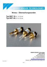
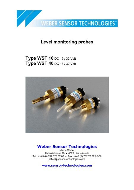
<strong>Level</strong> <strong>monitoring</strong> <strong>probes</strong><br />
<strong>Type</strong> <strong>WST</strong> <strong>10</strong> DC 9 / 32 Volt<br />
<strong>Type</strong> <strong>WST</strong> 40 DC 18 / 32 Volt<br />
Weber Sensor Technologies<br />
Martin Weber<br />
Zollamtstrasse 28 • 4020 Linz - Austria<br />
Tel.: ++43 (0) 732 / 78 37 02 • Fax: ++43 (0) 732 78 37 02-50<br />
office@sensor-technologies.com<br />
www.sensor-technologies.com
Index<br />
General description 3<br />
Installation instruction for all Weber sensors 5<br />
Functionality of level <strong>probes</strong> minimum 6<br />
Functionality of level <strong>probes</strong> maximum 7<br />
Probe type <strong>WST</strong> <strong>10</strong> with connector bayonet 16 S 8<br />
for a voltage range of 18 to 32 V<br />
Probe type <strong>WST</strong> 40 with connector bayonet 16 S <strong>10</strong><br />
for a voltage range of 18 - 32 V<br />
In addition to our standardised sensors we are in a position to develop sensors according to<br />
your specifications.<br />
- 2 -
General description<br />
Weber level <strong>monitoring</strong> <strong>probes</strong><br />
Our sensors monitor the level of oil-like and aqueous liquids. They are applied in commercial<br />
vehicles, power units, engines and ships. On engines they are employed to check the oil<br />
level, the coolant level and the fuel tank. On ships they are used to supervise engine states<br />
and supply and waste water tank and the bilge. The sensors are suitable for automatic liquid<br />
filling and refilling units, e.g. engine oil supply and the fuel service tank.<br />
In all situations where temperature sensors or manometric switches are currently used as<br />
level <strong>monitoring</strong> components, our probe has the advantage that it displays a critical operating<br />
state much sooner. Temperature sensors often respond with considerable delay because the<br />
medium which is checked no longer exists. As a result, the increase in temperature is not<br />
handed on to the generator. A manometric switch shows the lack of oil only in case of an<br />
entire lack of oil and thus too late to protect the engine. The level sensor gives a warning<br />
signal when there are insufficient quantities of the medium present.<br />
Weber level <strong>monitoring</strong> sensors differ from float-type switches in their compact design and<br />
immunity to vibrations. As they do not consist of any mechanically moved parts, their<br />
successful operation cannot be affected by dirt particles or other influences. On the probe no<br />
current is sent into the medium via an electrode. Thus an insulation of the sensor and<br />
electrolysis in the system is not possible.<br />
Operating principle<br />
The <strong>monitoring</strong> probe works on the capacitive principle. A change in capacitance is detected<br />
when an insulated electrode surrounded by air is immersed in a fluid medium. This change in<br />
capacitance is detected by sensor electrode which sets an oscillator in motion (frequency<br />
approx. 600 kHz). This signal is processed by a digital evaluation electronics unit.<br />
Switching output<br />
The level sensors have a short-circuit-resistant switching output,<br />
• Minus-switching: The output transistor switches the minus potential to the load.<br />
• Plus-switching: The output transistor switches the plus potential to the load.<br />
For switching currents of more than 1A, a relay must be interconnected. For this a freewheeling<br />
diode must be switched parallel to the relay as excess voltage protection at<br />
inductive load (see technical specifications).<br />
Medium variants<br />
The level sensors are configured for two different types of media:<br />
• For electrically conducting liquid media with a relative dielectric constant in the range of<br />
εr: 35...85 (water, coolant, water glucose mix)<br />
• And for non- electrically conducting liquid media with a relative dielectric constant in the<br />
rang of εr: 1,8...6 (engine oil, fuels, hydraulic oil)<br />
- 3 -
Automatic function control<br />
The sensors are fitted as standard with approx. 2 second function control. If the supply<br />
voltage is applied (e.g. ignition is initiated), the signal appears for approx. 2 seconds and<br />
thus signals that the sensor is ready. If the signal does not appear then the sensor needs to<br />
be checked. This self-<strong>monitoring</strong> allows the level <strong>monitoring</strong> sensor to be checked for<br />
functional readiness as well as cable breakage from a central point. The control of<br />
conventional level switches is extremely difficult especially in large- scale branching systems<br />
such as those found on ships. Other function control times can be supplied on request.<br />
Reporting delay<br />
In order to avoid faulty readings caused by fluctuating liquid surfaces and thus the brief<br />
deviations above or below the level that this produces, the output signal comes fitted with a<br />
reporting delay period of about 7 seconds. Other reporting delay on request.<br />
- 4 -
Installation instruction<br />
All WEBER <strong>monitoring</strong> sensors may be installed in any attitude.<br />
Please observe the following instructions when installing the probe:<br />
1. To prevent false indication, install the probe in a smooth area where it is not affected by<br />
splashing media as may be the case when it is installed in a gear unit or directly in the<br />
motor oil slump.<br />
2. To prevent false indication, install the sensor at least 15 min from the wall away.<br />
Only for water- sensors:<br />
3. False indication may also occur if the sensor is mounted from above in a plastic<br />
container, with the medium carrying no potential. In all other mounting attitudes the<br />
housing will be in contact with the medium so as to ensure potential is available.<br />
4. Connection Diagram<br />
- 5 -
Functionality: level <strong>probes</strong> minimum<br />
Minimum<br />
Output works<br />
Output does<br />
not work<br />
Minimum <strong>probes</strong>:<br />
Probe in<br />
medium Probe in medium<br />
Probe out of medium<br />
Switching<br />
delay<br />
If a minimum probe is removed from the medium, its outlet becomes active after the report<br />
delay. Its outlet becomes low-impedance after the report delay and a signal is available at<br />
the outlet.<br />
If a minimum probe is immersed in the medium, its outlet immediately becomes passive. Its<br />
outlet becomes high-impedance after immersion and a signal is no longer available at the<br />
outlet.<br />
- 6 -
Functionality: level <strong>probes</strong> maximum<br />
Output works<br />
Output does<br />
not work<br />
Probe in<br />
medium<br />
Maximum <strong>probes</strong>:<br />
Switching<br />
delay<br />
Probe out of medium<br />
If a maximum probe is immersed in the medium, its outlet becomes active after the report<br />
delay. The outlet becomes low-impedance after the report delay and a signal is available at<br />
the outlet.<br />
If a maximum probe is removed from the medium, its outlet immediately becomes passive.<br />
The outlet becomes high-impedance after the removal and there is no longer a signal<br />
available at the outlet.<br />
- 7 -<br />
Probe in medium
Technical data for type <strong>WST</strong> <strong>10</strong> at TU = 20 °C<br />
Operating voltage:<br />
Power consumption:<br />
Load carrying capacity of exit S:<br />
Switching point vertically mounted:<br />
Switching point horizontally mounted:<br />
Medium temperature:<br />
Ambient temperature:<br />
Storage temperature:<br />
Response delay:<br />
Integral control function:<br />
Reverse polarity protection:<br />
Function:<br />
Caution:<br />
DC 9 to 32 V<br />
5 to <strong>10</strong> mA (without load)<br />
up to 1 A (resistive and inductive load, short-circuit proof, overload<br />
protected in the whole operating voltage and temperature range);<br />
<strong>10</strong> to 25mm from feeler nib<br />
2.5 mm ± 1 mm<br />
-40 °C to +<strong>10</strong>5 °C<br />
-40 °C to +<strong>10</strong>5 °C<br />
-40 °C to +<strong>10</strong>5 °C<br />
see product table on following pages<br />
see product table on following pages<br />
in-built between plus and minus terminal<br />
see product table on following pages<br />
Minus switching <strong>probes</strong>: Do not connect minus potential to the signal terminal or plus<br />
potential to the minus terminal, as otherwise the <strong>probes</strong> may be destroyed.<br />
CE marking according to EC-directive 89/336/EWG (EMC directive)<br />
- 8 -
<strong>Type</strong> <strong>WST</strong> <strong>10</strong> with bayonet 16 S<br />
Environmental protection IP 67 DIN 40050<br />
Probe suitable for aqueous media Probe suitable for oil or fuel<br />
<strong>Type</strong> <strong>WST</strong> <strong>10</strong> with bayonet 16 S Signal output<br />
minus potential<br />
Thread Monitoring Integral control Monitoring Aqueous liquids<br />
Oil and fuel<br />
display function delay<br />
Ref. No.<br />
Ref. No.<br />
M 14 x 1,5 MIN 2 sec. 7 sec. <strong>10</strong><strong>10</strong>575 <strong>10</strong>20595<br />
M 14 x 1,5 MIN 0 sec. 0 sec. <strong>10</strong><strong>10</strong>528 ----<br />
M 14 x 1,5 MIN 2 sec. 15 sec. <strong>10</strong><strong>10</strong>637 ----<br />
M 14 x 1,5 MIN 1 sec. 2 sec. <strong>10</strong><strong>10</strong>502 ----<br />
M 14 x 1,5 MIN 0 sec. 7 sec. <strong>10</strong><strong>10</strong>564 <strong>10</strong>20590<br />
M 14 x 1,5 MIN 2 sec. 0 sec. ---- <strong>10</strong>20562<br />
M 18 x 1,5 MIN 2 sec. 7 sec. <strong>10</strong><strong>10</strong>570 <strong>10</strong>20572<br />
M 18 x 1,5 MIN 0 sec. 7 sec. ---- <strong>10</strong>20031<br />
1/4“NPTF MIN 2 sec. 7 sec. <strong>10</strong><strong>10</strong>577 <strong>10</strong>20597<br />
1/4“NPTF MIN 1 sec. 17 sec. <strong>10</strong><strong>10</strong>401 ----<br />
1/4“NPTF MIN 0 sec. 7 sec. <strong>10</strong><strong>10</strong>581 ----<br />
1/4“NPTF MIN 0 sec. 20 sec. <strong>10</strong><strong>10</strong>636 ----<br />
1/4“NPTF MIN 6 sec. 15 sec. <strong>10</strong><strong>10</strong>500 ----<br />
1/4“NPTF MIN 0 sec. 0 sec. ---- <strong>10</strong>20529<br />
Accessories for <strong>probes</strong> with bayonet 16 S<br />
Ref. No. Description<br />
<strong>10</strong>00672 Straight connector for bayonet 16 S, for corrugated tubing NW <strong>10</strong><br />
<strong>10</strong>00673 90° connector for bayonet 16 S, for corrugated tubing NW <strong>10</strong><br />
<strong>10</strong>00772 Straight connector for bayonet 16 S with 5.6 mm cable sealing<br />
<strong>10</strong>00773 90° connector for bayonet 16 S with 5,6 mm cable sealing<br />
<strong>10</strong>00641 Braze-in adapter 1/4"NPTF<br />
<strong>10</strong>00644 Braze-in adapter M14x 1,5<br />
<strong>10</strong>00648 Braze-in adapter M18x 1,5<br />
- 9 -
Technical data for type <strong>WST</strong> 40 at TU = 20 °C<br />
Operating voltage:<br />
Power consumption:<br />
Switching capacity:<br />
Switching point vertically mounted:<br />
Switching point horizontally mounted:<br />
Medium temperature:<br />
Ambient temperature:<br />
Storage temperature:<br />
Response delay:<br />
Integral control function:<br />
Function:<br />
Housing:<br />
Caution:<br />
DC 18 to 32 V<br />
<strong>10</strong>-15 mA (without load)<br />
max. 2 W (resistive Last, not overload protected)<br />
<strong>10</strong> to 25mm from feeler nib<br />
2.5 mm ± 1 mm<br />
-30 °C to +1<strong>10</strong> °C<br />
-30 °C to +<strong>10</strong>0 °C<br />
-40 °C to +115 °C<br />
see product table on following pages<br />
see product table on following pages<br />
see product table on following pages<br />
minus potential<br />
Minus switching <strong>probes</strong>: Do not connect minus potential to the signal terminal or plus<br />
potential to the minus terminal, as otherwise the <strong>probes</strong> may be destroyed.<br />
- <strong>10</strong> -
<strong>Type</strong> <strong>WST</strong> 40 with bayonet 16 S<br />
Environmental protection IP 67 DIN 40050<br />
Probe suitable for<br />
aqueous media<br />
<strong>Type</strong> <strong>WST</strong> 40 with bayonet 16 S Signal output<br />
minus potential<br />
Thread Monitoring Integral control Response Aqueous liquids<br />
Oil and fuel<br />
display function delay<br />
Ref. No.<br />
Ref. No.<br />
M 14 x 1,5 MIN 2 sec. 7 sec. 421575-24V 421595-24V<br />
M 14 x 1,5 MAX 0 sec. 7 sec. 421579-24V 421599-24V<br />
1/4“NPTF MIN 2 sec. 7 sec. 421577-24V 421597-24V<br />
1/4“NPTF MAX 0 sec. 7 sec. 420993-24V -----<br />
Accessories for bayonet 16 S<br />
Ref. No. Description<br />
<strong>10</strong>00672 Straight connector for bayonet 16 S, for corrugated tubing NW <strong>10</strong><br />
<strong>10</strong>00673 90° connector for bayonet 16 S, for corrugated tubing NW <strong>10</strong><br />
<strong>10</strong>00772 Straight connector for bayonet 16 S with 5.6 mm cable sealing<br />
<strong>10</strong>00773 90° connector for bayonet 16S with 5.6 mm cable sealing<br />
<strong>10</strong>00641 Braze-in adapter 1/4"NPTF<br />
<strong>10</strong>00644 Braze-in adapter M14x 1,5<br />
<strong>10</strong>00648 Braze-in adapter M18x 1,5<br />
- 11 -<br />
Probe suitable for<br />
oil or fuel