Owners manual - Zupin
Owners manual - Zupin
Owners manual - Zupin

You also want an ePaper? Increase the reach of your titles
YUMPU automatically turns print PDFs into web optimized ePapers that Google loves.
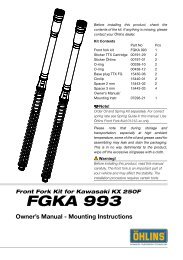
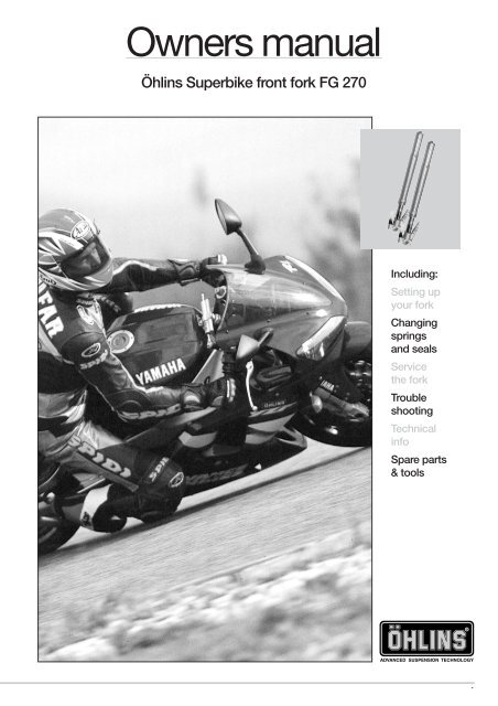
<strong>Owners</strong> <strong>manual</strong><br />
Öhlins Superbike front fork FG 270<br />
Including:<br />
Setting up<br />
your fork<br />
Changing<br />
springs<br />
and seals<br />
Service<br />
the fork<br />
Trouble<br />
shooting<br />
Technical<br />
info<br />
Spare parts<br />
& tools<br />
1
Öhlins super bike front fork<br />
FG 270<br />
2<br />
730<br />
STROKE 125<br />
ø52<br />
ø58<br />
ø60<br />
22<br />
44<br />
13.3<br />
155<br />
30<br />
315<br />
522<br />
Contents<br />
Introduction .................................... 2<br />
Setting up your forks<br />
Spring preload adjustment .............. 3<br />
Rebound adjustment<br />
Compression adjustment<br />
Changing springs<br />
Changing seals<br />
Dismantling the forks ...................... 4<br />
Assembly of the forks<br />
Troubleshooting<br />
Oil level adjustment ......................... 5<br />
Technical information<br />
Spare parts ..................................... 6<br />
Tools<br />
Safety signals<br />
Important information concerning safety<br />
is distinguished in this <strong>manual</strong> by the<br />
following notations.<br />
The Safety alert symbol means:<br />
Caution! Your safety is involved.<br />
WARNING!<br />
Failure to follow warning instructions<br />
could result in severe or fatal injury<br />
to anyone working with, inspecting or<br />
using the suspension, or to bystanders.<br />
CAUTION!<br />
Caution indicates that special<br />
precautions must be taken to avoid<br />
damage to the suspension.<br />
NOTE!<br />
This indicates information that is of<br />
importance with regard to procedures.<br />
Kit contents<br />
Before installing the front fork, please<br />
check the contents of the kit, listed in<br />
the mounting instruction. If anything is<br />
missing, contact your Öhlins dealer.<br />
NOTE!<br />
During storage and transportation,<br />
especially at high ambient temperature,<br />
the oil and grease used for assembling<br />
may run out inside the packing and<br />
damage the expanded polystyrene<br />
packing material. This is not unusual<br />
and is in no way detrimental to the<br />
shock absorber.<br />
© Öhlins Racing AB.<br />
All rights reserved.<br />
Any reprinting or unauthorized use<br />
without the written permission of<br />
Öhlins Racing AB is prohibited.<br />
Printed in Sweden.<br />
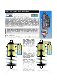
Introduction<br />
The Öhlins front forks use a Cartridge<br />
system for damping. This gives a damping<br />
force which depends on the speed of the<br />
piston in the cartridge system.<br />
The combination of spring and air-gap<br />
(oil level) gives a possibility to adjust the<br />
characteristic of the fork to suit different<br />
tracks and riders.<br />
For example a soft spring in combination<br />
with a small air-gap (high oil level)<br />
gives a progressive action of the front<br />
forks.<br />
For better understanding, please refer<br />
to our oil level chart.<br />
A telescopic front fork is depending<br />
on a smooth friction-free action.<br />
Make sure your front forks are<br />
serviced regularly and don’t use strong<br />
solvents such as brake cleaner to clean<br />
the front forks. This will dry out the seals<br />
and steel tubes and cause friction.<br />
Regularly, put a little Öhlins grease<br />
(148-01) on the steel tube and work it in<br />
by pushing the forks up and down.<br />
Öhlins Racing AB can not be held<br />
responsible for any damage to spare parts<br />
or person if the mounting-, maintaining<br />
and servicing instructions are not followed<br />
exactly.<br />
Also no guarantee can be given for the<br />
performance and reliability if these<br />
instructions are not followed.<br />
Setting up your forks<br />
We would like to give you some basic<br />
guidelines, how to set up your Öhlins<br />
front forks. However you must remember<br />
that the front forks are just one part of<br />
your motorcycle and to get it to work<br />
properly, the whole motorcycle has to be<br />
set up according to your bikes <strong>manual</strong>.<br />
1<br />
Put your bike on a front stand so you<br />
can fit the front forks.<br />
NOTE!<br />
The lower triple clamp must not be<br />
tightened to more than 15-18 Nm. This<br />
is also important for the steering<br />
damper bracket, when it is located<br />
around the upper front leg. To high<br />
torque might deform the front fork leg.<br />
Fit the front wheel and brakes.<br />
2<br />
Unscrew the adjustment housing on top<br />
of the fork (use tool 4703-01) on both<br />
upper tubes and slide the fork up and<br />
down gentle to make sure everything<br />
works correctly.<br />
3<br />
Assemble the adjustment housing again<br />
and set your initial preload of the spring<br />
by using a 17 mm socket until you get a<br />
”static sag” of 25-30 mm.<br />
Each turn gives 1 mm in preload,<br />
maximum preload is 18 mm.
4<br />
The best way to check the ”static sag”<br />
is to put the bike on the ground in<br />
running condition.<br />
Measure the distance between the<br />
bottom of the outer tube to the fork<br />
bottom.<br />
Then lift the front end of the bike, so<br />
the fork is fully extended.<br />
Take the measurement again. The<br />
difference between those two figures is<br />
”static sag”.<br />
5<br />
The ”clickers” are a ”bleed function”<br />
separate for rebound and compression<br />
damping.<br />
Rebound is on the top centre of the<br />
fork and compression at the bottom part<br />
of the fork.<br />
You start to count from fully closed<br />
(clockwise) and set it to the recommended<br />
”click” (use tool 794-01).<br />
For recommended start setting please<br />
refer to the specification card.<br />
Spring preload adjustment<br />
Using a 17 mm wrench, turn the upper<br />
adjustment screw.<br />
Maximum adjustment range is 18 mm.<br />
One turn on the adjustment screw will<br />
cause 1 mm change in spring preload.<br />
Adjust so the front forks lowers 25-<br />
30 mm from the top, unloaded position.<br />
Rebound adjustment<br />
Adjust the rebound rate on the adjustment<br />
screws positioned at the top centre of the<br />
front forks.<br />
Use a hex key with a spherical head<br />
(use tool 794-01).<br />
Adjustment range from closed valve<br />
(clockwise) until maximum open valve<br />
(anticlockwise) is 20 ”clicks”.<br />
Recommended adjustment ”click”,<br />
from closed position<br />
(see specification card).<br />
Compression adjustment<br />
Adjust the compression rate on the lower<br />
part of the front forks (compression<br />
valve). Use a screw driver.<br />
Adjustment range from closed valve<br />
(clockwise) to maximum open valve<br />
(anticlockwise) is 20 ”clicks”.<br />
Recommended adjustment ”clicks”,<br />
from closed position.<br />
see specification card.<br />
Changing springs<br />
1<br />
Loosen the screws that hold the fork<br />
legs in the upper triple clamps.<br />
2<br />
Loosen the top nut assembly (pos 7,<br />
page 7) about two turns (use tool 4703-<br />
01).<br />
3<br />
Remove the fork legs from the<br />
motorcycle.<br />
4<br />
Fasten a fork leg in a vice. Use soft jaws.<br />
5<br />
Unload the spring completely by turning<br />
the adjustment screw completely<br />
anticlockwise.<br />
Use a 17 mm wrench.<br />
6<br />
Carefully loosen the top nut assembly<br />
from piston shaft<br />
7<br />
Remove the preload tube and spring.<br />
(The free spring length see page 5).<br />
8<br />
Install the new spring and check the oil<br />
level. Install the tool 1765-02 on top of<br />
the piston shaft extension. Pull out the<br />
piston rod as far as possible and turn<br />
the compression adjustment screw fully<br />
clockwise. This will keep the piston rod<br />
in top position, which will make the<br />
continued assembly easier.<br />
9<br />
Install the preload tube. Pull the piston<br />
rod out to fully extended. Push it<br />
sideways and lock the rod extensioner<br />
against the piston preload tube.<br />
10<br />
Install the top nut assembly.<br />
11<br />
Install the fork legs on the motorcycle<br />
and adjust the preload, compression<br />
and rebound according to the above<br />
instructions.<br />
Changing seals<br />
Put the fork legs upright for 15 minutes.<br />
1<br />
Fasten the fork leg in a vice. Use soft jaws.<br />
2<br />
Unload the spring preload completely<br />
by turning the adjustment screw<br />
completely anticlockwise.<br />
Use a 17 mm wrench.<br />
Make a note of the number of turns.<br />
3<br />
Carefully remove the adjustment<br />
housing.<br />
4<br />
Remove the preload tube.<br />
5<br />
Slide the outer fork leg up until the top<br />
bushing is just above the inner leg.<br />
(Approx. 140 mm from complete bottom<br />
position.<br />
This is to make sure there is no oil<br />
above the top bushing).<br />
6<br />
Slide the outer tube completely down.<br />
(Fork seal touching fork bottom).<br />
7<br />
Push the piston rod down so that it is in<br />
level with the top of the outer tube.<br />
Measure the oil level using the top of<br />
the outer tube as the zero mark. Note<br />
the measurement.<br />
NOTE!<br />
When measuring the oil level, always<br />
have the spring installed.<br />
8<br />
Remove the spring and tip the oil in a<br />
clean container.<br />
9<br />
Remove the outer tube, clean the seals<br />
and check for damaged, if the seals are<br />
damaged remove and replace.<br />
If the seals are OK, then apply with<br />
Öhlins grease (green grease 148-01).<br />
10<br />
Apply Öhlins fork oil on the seals and<br />
on the inner tube.<br />
12<br />
Carefully mount outer tube (slide<br />
completely down) install spring and set<br />
the oil level.<br />
13<br />
Go on with 9 to 11 according to<br />
"Changing springs" above.<br />
3
Dismantling the forks<br />
1<br />
Carry out 1 to 7 of page 3 "Changing<br />
springs".<br />
2<br />
Free the fork leg from the vice and drain<br />
the oil.<br />
3<br />
Pull up the outer tube and remove the<br />
seals.<br />
4<br />
Fasten the inner tube on the fork bottom<br />
in a vice. Use soft jaws!<br />
5<br />
Unscrew the seal head (pos 14, page 7)<br />
from the cartridge tube and remove the<br />
piston rod unit (use tool 1797-02).<br />
Drain the remaining oil.<br />
6<br />
Remove the complete compression<br />
valve use a 17 mm wrench.<br />
7<br />
Remove the piston and the shims from<br />
the piston rod and compression valve.<br />
Place the shims in their correct position<br />
on the work bench.<br />
8<br />
Clean all parts thoroughly and dry with<br />
compressed air.<br />
Assembly of the forks<br />
1<br />
Apply a thin layer of Öhlins green grease<br />
(148-01) on the scraper ring and on the<br />
sealing surfaces of the fork seal.<br />
Install the seals in the outer tube.<br />
Please note that it is important to use<br />
the correct grease in order to achieve<br />
optimum fork function.<br />
2<br />
Install the piston and the shims on the<br />
piston rod and the compression valve.<br />
Tighten the 8 mm lock nuts with a torque<br />
of 7 Nm.<br />
Check the piston ring for damages.<br />
Replace if necessary.<br />
3<br />
Install the compression valve assembly<br />
into the valve housing.<br />
4<br />
Apply some front fork oil 1305-01 on<br />
the inner steel tube surface and install<br />
the outer aluminium tube.<br />
Measure the correct amount of 1305-<br />
01 oil according to the specification<br />
card.<br />
4<br />
CAUTION!<br />
Be careful not to damage the fork leg<br />
seals.<br />
5<br />
Raise the outer tube approximately 120<br />
mm and fill the oil.<br />
Install the complete piston rod into<br />
the cartridge tube.<br />
6<br />
Lightly tighten the seal head using tool<br />
1797-02.<br />
7<br />
Mount tool 1765-02<br />
8<br />
Pump the piston rod up and down and<br />
the oil will be sucked into the cartridge<br />
tube. Close the “clickers” and check the<br />
function.<br />
9<br />
Pull the piston rod out as far as possible<br />
and close the compression valve<br />
screw completely (clockwise).<br />
10<br />
Go on with 8 to 11 according to page 3<br />
"Changing springs".<br />
Trouble shooting<br />
Below are a few examples of how to<br />
adjust for the most common road<br />
holding problems in Road Racing<br />
driving.<br />
A<br />
The front wheel ”chatters” entering<br />
a corner, the problem goes away, as<br />
soon as you let the brakes off, or<br />
when you get on the power.<br />
This is caused by the fact that the fork<br />
is working too low in the travel and<br />
reaches the progressive, hard part at the<br />
end of the travel.<br />
1<br />
Put on more preload.<br />
2<br />
Change to a harder spring.<br />
3<br />
If a lot of stroke remains after riding, drop<br />
the oil level. See oil level chart.<br />
4<br />
Make sure the front forks have no friction.<br />
5<br />
Rear ride height is to high, too much<br />
rear spring preload.<br />
Lower the rear end by taking off preload<br />
from rear shock spring.<br />
B<br />
The front wheel is jumping during the<br />
last part of braking.<br />
1<br />
If a lot of stroke remains, the oil level is<br />
too high. Lower the oil level.<br />
2<br />
If the fork is bottoming, put in harder<br />
springs and keep the oil level.<br />
C<br />
The front end feels unpredictable and<br />
unsafe in the middle of the corner<br />
(between braking and getting on<br />
power).<br />
1<br />
Not enough rebound damping. Put on<br />
more damping.<br />
2<br />
Too much rebound damping. If it at the<br />
same time feels harsh, take off some<br />
rebound damping.<br />
3<br />
Too much compression damping. Also<br />
gives a harsh feeling. Take off some<br />
compression damping.<br />
D<br />
The front end loses grip coming out<br />
of a corner.<br />
1<br />
Not enough rebound damping. Put on<br />
some more rebound damping.<br />
2<br />
Too much preload. Take off some<br />
preload.<br />
3<br />
Rear end is too soft. Put on a harder<br />
rear spring.<br />
4<br />
Front end is too high. Lower the front<br />
end by pulling the fork legs through the<br />
triple clamps.<br />
As mentioned in the beginning, the<br />
whole bike setup affects the front forks.<br />
Try to understand the feelings and work<br />
step by step.<br />
NOTE!<br />
Our advice is to change only one thing<br />
at a time and do everything step by<br />
step.
Oil level<br />
Force [N]<br />
1000<br />
900<br />
800<br />
700<br />
600<br />
500<br />
400<br />
300<br />
200<br />
100<br />
Air spring characteristics FG 270<br />
Oil level 100<br />
Oil level 110<br />
Oil level 120<br />
Oil level 130<br />
Oil level 140<br />
Oil level 150<br />
Oil level 160<br />
0<br />
0 20 40 60 80 100 120 140<br />
Stroke [mm]<br />
Oil level adjustment<br />
Compared with conventional type of<br />
front forks, the upside down front forks<br />
are very sensitive to variations in oil level.<br />
Therefore, adjust the oil level with special<br />
care.<br />
A change in the fork oil level will not<br />
affect the damping force at the early<br />
stage of the fork travel, but will have a<br />
great effect at the later stage.<br />
When the oil level is raised:<br />
The air spring in the later half stage of<br />
travel is stronger, and thus the front forks<br />
harder.<br />
When the oil level is lowered:<br />
The air spring in the later half stage of<br />
travel is lessened, and thus the front fork<br />
softer.<br />
The oil level works most efficent at<br />
the end of the fork travel.<br />
Air spring characteristics shown, is a<br />
general card description to understand<br />
the difference when the oil level is<br />
changed.<br />
NOTE!<br />
Adjust the oil level in mm according to<br />
the figure with the fork fully compressed<br />
and with the spring mounted.<br />
For the right STD-level, please see<br />
the specification card.<br />
Notes<br />
Technical information<br />
Fork length:<br />
730 mm.<br />
Stroke:<br />
125 mm.<br />
Free spring length:<br />
240 mm.<br />
Rebound adjustment:<br />
Base setting 9-12 ”clicks”.<br />
Maximum open valve 20 ”clicks”.<br />
Compression adjustment:<br />
Base setting 6-16 ”clicks”.<br />
Maximum open valve 20 ”clicks”.<br />
Spring preload adjustment:<br />
0-18 mm (0-18 turns).<br />
Spring rate:<br />
4745-95, 9.5 N/mm (marking -95).<br />
Optional springs supplied:<br />
4745-10, 10.0 N/mm (marking -10).<br />
4745-90, 9.0 N/mm (marking -90).<br />
Optional springs:<br />
4745-05 10.5 N/mm (marking -05).<br />
4745-85 8.5 N/mm (marking -85).<br />
4745-80 8.0 N/mm (marking -80).<br />
4745-75 7.5 N/mm (marking -75).<br />
4745-70 7.0 N/mm (marking -70).<br />
4745-65 6.5 N/mm (marking -65).<br />
Oil Capacity:<br />
Please see specification card.<br />
Use Öhlins high performance front fork fluid<br />
No. 5 (1305-01) only.<br />
Loctite glue:<br />
542 on Fork Bottom thread.<br />
Tighten torque:<br />
Triple Clamp bolt 15-18 Nm.<br />
Grease:<br />
Öhlins front fork grease 148-01 (green<br />
grease).<br />
Service interval:<br />
Every 10hours<br />
5
6<br />
1<br />
2<br />
3<br />
4<br />
5<br />
6<br />
18<br />
17<br />
7<br />
7<br />
8<br />
9<br />
10<br />
11<br />
12<br />
19<br />
25<br />
16<br />
23<br />
20<br />
22<br />
21<br />
24<br />
20<br />
1<br />
22<br />
13<br />
14<br />
15<br />
21<br />
Spare parts<br />
Fig. Part No. Description Pieces<br />
1-01 04732-02 Top nut assembly 2<br />
1-02 01408-02 Adjustment driver 2<br />
1-03 01460-35 Preload tube 2<br />
1-04 01438-04 Guide ring 2<br />
1-05 04745-90 Spring 2<br />
04745-95 Spring 2<br />
04745-10 Spring 2<br />
1-06 01900-03 Fork leg outer 2<br />
1-07 01683-02 Bushing, upper 2<br />
01684-02 Bushing, lower 2<br />
1-08 04758-01 Washer 2<br />
1-09 04720-01 Bushing 2<br />
1-10 04759-01 Circlip 2<br />
1-11 01564-04 Stroke indicator 1<br />
1-12 00338-63 O-ring 1<br />
1-13 01656-01 Cylinder tube 2<br />
1-14 01699-02 Fork leg inner 2<br />
1-15 00194-10 Sticker 2<br />
1-16 01696-02 Fender bracket 2<br />
1-17 01694-02 Compr. valve housing 2<br />
1-18 01046-34 Bolt 4<br />
1-19 00338-07 O-ring 4<br />
1-20 01046-01 Bolt 3<br />
1-21 01046-22 Bolt 4<br />
1-22 01046-25 Bolt 4<br />
1-23 01902-03 Fork bottom 2<br />
1-24 01593-05 Caliper bracket LH 1<br />
01593-06 Caliper bracket RH 1<br />
1-25 01593-07 Caliper bracket LH 1<br />
01593-08 Caliper bracket RH 1
1<br />
1<br />
2<br />
3<br />
4<br />
5<br />
6<br />
7<br />
8<br />
9<br />
10<br />
11<br />
12<br />
13<br />
2 3<br />
14<br />
15<br />
16<br />
17<br />
18<br />
19<br />
20<br />
21<br />
22<br />
23<br />
24<br />
25<br />
26<br />
27<br />
4<br />
5<br />
6<br />
2<br />
28<br />
29<br />
30<br />
31<br />
32<br />
33<br />
34<br />
35<br />
36<br />
37<br />
38<br />
39<br />
40<br />
41<br />
42<br />
43<br />
44<br />
3<br />
Spare parts<br />
Fig. Part No. Description Pieces<br />
2-01 02366-04 Adjustment rod 2<br />
2-02 01901-01 Adjustment screw 2<br />
2-03 01648-01 Lock nut 2<br />
2-04 01499-02 Circlip 2<br />
2-05 01649-01 Stop screw 2<br />
2-06 01580-01 Bump rubber 2<br />
2-07 01651-02 Seal head 2<br />
2-08 00110-01 Bushing 2<br />
2-09 01613-01 X-ring 2<br />
2-10 01582-12 Spacer 2<br />
2-11 01653-01 Sleeve 2<br />
2-12 01585-11 Topout spring 2<br />
2-13 02367-03 Shaft 2<br />
2-14 00438-31 O-ring 2<br />
2-15 01698-10 Rebound needle 2<br />
2-16 02332-01 Spring 2<br />
2-17 01654-03 Piston holder 2<br />
2-18 01699-01 Sleeve 2<br />
2-19 01672-01 Spring collar 2<br />
2-20 01671-02 Spring 2<br />
2-21 00530-22 Shims 2<br />
2-22 02061-01 Piston, rebound 2<br />
2-23 01447-01 Piston ring 2<br />
2-24 Shims see spec card<br />
2-25 00641-01 Washer 2<br />
2-26 01674-01 Washer 6<br />
2-27 01657-01 Nut 2<br />
2-28 01473-02 Circlip 2<br />
2-29 00338-53 O-ring 2<br />
2-30 01242-03 Adjustment needle 2<br />
2-31 01248-01 Spring 2<br />
2-32 00884-04 Ball 2<br />
2-33 00438-02 O-ring 2<br />
2-34 01695-01 End piece 2<br />
2-35 00641-01 Washer 2<br />
2-36 Shims see spec card<br />
2-37 01670-01 Piston 2<br />
2-38 00338-11 O-ring 2<br />
2-39 01669-01 Sleeve 2<br />
2-40 00530-22 Shim 2<br />
2-41 01693-01 Spring 2<br />
2-42 01672-01 Spring collar 2<br />
2-43 00120-01 Washer 2<br />
2-44 01675-01 Nut 2<br />
Service tools<br />
Part No. Description<br />
3-01 01765-02 Pull-up top-out spring tool<br />
3-02 00787-04 Cylinder tube tool (cartridge)<br />
3-03 00786-05 Inner tube tool<br />
3-04 01797-02 Seal head tool<br />
3-05 04703-01 Top nut socket<br />
3-06 00794-01 Hex key with spherical head<br />
7
8<br />
More info<br />
www.ohlins.com<br />
The ultimate suspension site.<br />
Find out everything about your suspension.<br />
Download mounting instructions, <strong>manual</strong>s and brochures.<br />
And a lot more.<br />
Öhlins Racing AB, Box 722, S-194 27 Upplands Väsby, Sweden<br />
Phone +46 8 590 025 00, Fax +46 8 590 025 80<br />
Your Öhlins dealer:<br />
07280-08 Teknisk Illustration AB, OM super bike front fork, FG 270, 02 01. 150 ex.