Trabalhos de Fim de Curso: - Departamento de Engenharia ...
Trabalhos de Fim de Curso: - Departamento de Engenharia ...
Trabalhos de Fim de Curso: - Departamento de Engenharia ...

You also want an ePaper? Increase the reach of your titles
YUMPU automatically turns print PDFs into web optimized ePapers that Google loves.
INSTITUTO<br />
SUPERIOR<br />
TÉCNICO<br />
SECÇÃO DE<br />
SISTEMAS<br />
<strong>Trabalhos</strong> <strong>de</strong> <strong>Fim</strong> <strong>de</strong> <strong>Curso</strong>:<br />
Documentação e<br />
Normas <strong>de</strong> redacção e apresentação
IST - DEM – Secção <strong>de</strong> Sistemas Normas <strong>de</strong> redacção e apresentação - 1<br />
NORMAS DE REDACÇÃO E APRESENTAÇÃO<br />
As disciplinas <strong>de</strong> Projecto <strong>de</strong> Sistemas I e Projecto <strong>de</strong> Sistemas II estão<br />
integradas, tendo como objectivo fazer a síntese das matérias leccionadas<br />
nas diversas disciplinas do curso, através da aplicação <strong>de</strong>sses<br />
conhecimentos à resolução <strong>de</strong> um projecto <strong>de</strong> engenharia.<br />
No final, por forma a documentar e permitir a divulgação dos trabalhos<br />
realizados, serão elaborados pelo grupo <strong>de</strong> projecto: um relatório final;<br />
uma folha sumário do trabalho <strong>de</strong>senvolvido; um relatório interno; e um<br />
poster, recomendando-se que os últimos três elementos sejam redigidos em<br />
língua inglesa.<br />
Como documentação <strong>de</strong> referência, serão entregues: três exemplares do<br />
relatório final (integrando um CD contendo todos os elementos <strong>de</strong> avaliação em versão<br />
editável); um do relatório interno; um da folha <strong>de</strong> sumário e um poster.<br />
A avaliação do projecto é efectuada através <strong>de</strong> oral pública, individual por<br />
trabalho, realizada por um júri, nomeado pelo responsável das disciplinas.<br />
A classificação final é atribuída com base num conjunto <strong>de</strong> factores<br />
nomeadamente: o relatório final, a apresentação oral e a discussão do<br />
projecto.<br />
Dez por cento da nota final correspon<strong>de</strong> à avaliação periódica da evolução<br />
do projecto, a qual consta da entrega <strong>de</strong> uma folha sumário e uma<br />
apresentação sumária (~10 min) dos trabalhos em curso por cada um dos<br />
grupos – baseada em acetatos explicativos dos trabalhos <strong>de</strong>senvolvidos, em<br />
curso e futuros – e da entrega <strong>de</strong> um relatório intercalar, com o máximo <strong>de</strong><br />
<strong>de</strong>z páginas.<br />
Dos parágrafos anteriores (extraídos das regras para elaboração do Projecto<br />
<strong>de</strong> Sistemas I e II, enquadradas nas Regras Gerais <strong>de</strong> Projectos <strong>de</strong>finidas<br />
DEM), conclui-se da necessida<strong>de</strong> <strong>de</strong> se elaborarem diversos tipos <strong>de</strong><br />
documentos escritos e <strong>de</strong> serem apresentadas diversas comunicações orais<br />
com apoio audiovisual, para cumprir as exigências estabelecidas e concluir<br />
com sucesso a disciplina.<br />
É sentimento comum, entre os professores orientadores dos trabalhos <strong>de</strong> fim<br />
<strong>de</strong> curso, que os jovens formandos, apresentam enorme dificulda<strong>de</strong> em se<br />
exprimirem correctamente.<br />
Desconhecendo as regras mínimas <strong>de</strong> apresentação das diferentes peças<br />
escritas que se lhes solicita, os alunos apresentam documentos avulso, em<br />
que investiram gran<strong>de</strong> parte do tempo <strong>de</strong>dicado à disciplina, mas on<strong>de</strong>,<br />
muitas das vezes, não conseguem mostrar o trabalho, que, brilhantemente,<br />
foram <strong>de</strong>senvolvendo ao longo <strong>de</strong> dois semestres. É sempre nas últimas<br />
horas que os tutores têm oportunida<strong>de</strong> <strong>de</strong> criticar as provas, apontando os<br />
caminhos e traçando orientações, já tardias, para uma redacção mais<br />
eficiente. Raramente, porém, tais conselhos extravasam os limites da<br />
documentação escrita. As apresentações orais e os seus apoios audiovisuais<br />
não são objecto <strong>de</strong> discussão com o discente para além da indicação <strong>de</strong><br />
leves referências.<br />
Rui Loureiro - 2004 Projecto <strong>de</strong> <strong>Fim</strong> <strong>de</strong> <strong>Curso</strong>
IST - DEM – Secção <strong>de</strong> Sistemas Normas <strong>de</strong> redacção e apresentação - 2<br />
Temos, os docentes, <strong>de</strong> assumir a responsabilida<strong>de</strong> que nos cabe nesta<br />
lacuna da formação dos nossos alunos. Po<strong>de</strong>mos afirmar, com razão, que<br />
não é da nossa responsabilida<strong>de</strong> as <strong>de</strong>ficiências <strong>de</strong> expressão oral e escrita<br />
dos nossos orientados, que tal se <strong>de</strong>ve a razões pedagógicas, cujos<br />
problemas têm raízes no ensino secundário. Porém não po<strong>de</strong>mos negar que<br />
nos compete a nós a preparação dos nossos discípulos para que estes<br />
possam vir a ocupar o seu lugar na comunida<strong>de</strong> cientifica. A ser assim, e<br />
porque se trata <strong>de</strong> uma comunida<strong>de</strong> que obriga os seus membros a produzir<br />
(relatórios, propostas <strong>de</strong> projectos, intervenções e comunicações) para<br />
sobreviver, somos os primeiros responsáveis porque eles saibam comunicar<br />
os seus trabalhos científicos.<br />
Tem este texto a intenção <strong>de</strong> colmatar aquela lacuna, apresentando linhas<br />
orientadoras, ainda que generalistas e necessariamente incompletas, da<br />
escrita e comunicação em ciência. Preten<strong>de</strong>-se que os nossos estudantes<br />
possuam um manual que os guie na estruturação dos seus escritos e na<br />
elaboração das suas apresentações.<br />
A panóplia <strong>de</strong> documentos escritos a apresentar para avaliação, po<strong>de</strong>m<br />
resumir-se aos tipos, Monografias, Artigos e Notícias, aos quais se<br />
acrescentam os Acetatos e Cartazes, para apoio das Apresentações Orais.<br />
Serão estes, porque necessários à disciplina, que iremos abordar e<br />
<strong>de</strong>screver ao longo <strong>de</strong>stas páginas.<br />
1. RELATÓRIO DO TRABALHO DE FIM DE CURSO<br />
O Relatório do Trabalho <strong>de</strong> <strong>Fim</strong> <strong>de</strong> <strong>Curso</strong> (TFC) é uma monografia , pois é<br />
um tipo específico <strong>de</strong> trabalho cientifico, que se reduz à abordagem <strong>de</strong> um<br />
tema específico do conhecimento. As teses <strong>de</strong> doutoramento e as<br />
dissertações <strong>de</strong> mestrado são também monografias.<br />
As monografias caracterizam-se pela <strong>de</strong>limitação e aprofundamento do tema<br />
escolhido, recorrendo, para se fundamentar, à pesquisa bibliográfica.<br />
São orientados para a realização <strong>de</strong> um trabalho concreto …tendo como<br />
objectivo fazer a síntese das matérias leccionadas nas diversas disciplinas do<br />
curso, através da aplicação <strong>de</strong>sses conhecimentos à resolução <strong>de</strong> um projecto <strong>de</strong><br />
engenharia (In Regras para elaboração do Projecto <strong>de</strong> Sistemas I e II).<br />
A estrutura dos TFC’s <strong>de</strong>ve seguir o sistema adoptado para as<br />
monografias, e não ter mais <strong>de</strong> 80 páginas:<br />
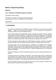
1.1. CAPA<br />
Inclui o nome do autor, título do trabalho e o ano <strong>de</strong> redacção.<br />
Deve seguir as normas estabelecidas pelo Manual <strong>de</strong> Harmonização <strong>de</strong><br />
Imagem do IST.<br />
A figura junta mostra o aspecto geral (e informações úteis) sobre a página<br />
que <strong>de</strong>ve capear o relatório.<br />
Rui Loureiro - 2004 Projecto <strong>de</strong> <strong>Fim</strong> <strong>de</strong> <strong>Curso</strong>
IST - DEM – Secção <strong>de</strong> Sistemas Normas <strong>de</strong> redacção e apresentação - 3<br />
As capas <strong>de</strong> relatório são<br />
impressas a azul escuro, Pantone<br />
287, conforme a ilustração.<br />
Para tornar possível a<br />
enca<strong>de</strong>rnação, a banda azul clara<br />
tem mais 15 mm <strong>de</strong> largura no<br />
lado esquerdo do que no lado<br />
direito. As margens superior e<br />
direita à volta do escudo são<br />
iguais ao restante material<br />
impresso <strong>de</strong> formato A4.<br />
O título, o nome do autor e o ano<br />
<strong>de</strong> publicação, são grafados em<br />
24/26pt em letra tipo “Times Bold”,<br />
letra maiúscula e minúscula,<br />
alinhado à esquerda.<br />
As informações adicionais são<br />
centradas impressas por sob o<br />
título, em letra <strong>de</strong> 12pt do tipo<br />
“Arial”.<br />
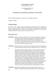
1.2. PÁGINA DE ROSTO<br />
Figura 1 – Capa do relatório do Trabalho <strong>de</strong> <strong>Fim</strong> <strong>de</strong> <strong>Curso</strong><br />
Folha imediatamente a seguir à capa<br />
(figura 3). Inclui o nome do autor, o<br />
número <strong>de</strong> aluno, o título do trabalho, o<br />
ano, a localida<strong>de</strong> e o nome do orientador,<br />
para além da i<strong>de</strong>ntificação completa do<br />
estabelecimento <strong>de</strong> ensino.<br />
No verso <strong>de</strong>sta folha (figura 2) <strong>de</strong>ve<br />
constar a seguinte frase:<br />
Este trabalho reflecte as i<strong>de</strong>ias dos seus autores<br />
que, eventualmente, po<strong>de</strong>rão não coincidir<br />
com as do Instituto Superior Técnico.<br />
1.3. AGRADECIMENTOS<br />
200<br />
265<br />
INSTITUTO<br />
SUPERIOR<br />
TÉCNICO<br />
SECÇÃO DE<br />
SISTEMAS<br />
Título …<br />
Relatório do Trabalho <strong>de</strong> <strong>Fim</strong> <strong>de</strong> <strong>Curso</strong><br />
Licenciatura em <strong>Engenharia</strong> Mecânica<br />
Ramo <strong>de</strong> Automação e Robótica<br />
Autor …….<br />
2004<br />
Sendo o relatório um documento público, que po<strong>de</strong>rá ser consultado na<br />
biblioteca da Secção <strong>de</strong> Sistemas, os agra<strong>de</strong>cimentos <strong>de</strong>vem ser redigidos<br />
com parcimónia. Tal não impe<strong>de</strong> porém que se agra<strong>de</strong>ça a todos aqueles<br />
que contribuíram, <strong>de</strong> alguma forma, para a realização do trabalho.<br />
Des<strong>de</strong> logo aos orientadores, a quem caberá uma palavra <strong>de</strong> apreço, e às<br />
instituições que possam ter financiado o trabalho <strong>de</strong>senvolvido.<br />
Rui Loureiro - 2004 Projecto <strong>de</strong> <strong>Fim</strong> <strong>de</strong> <strong>Curso</strong><br />
50<br />
80<br />
25<br />
Ffdfdfhdhhdhhnvjvn ,<br />
hgfgd dfgk bdsfhjd<br />
kjdfhhdf jdhf<br />
Ffdfdfhdhhdhhn<br />
70<br />
185<br />
Figura 2 – Verso da página <strong>de</strong> rosto
IST - DEM – Secção <strong>de</strong> Sistemas Normas <strong>de</strong> redacção e apresentação - 4<br />
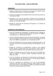
Grafados a maiúsculas a 26pt, centrados<br />
em letra tipo “Times New Roman” são o<br />
nome da Universida<strong>de</strong> e do Instituto<br />
(este a “Bold”). A 22pt, no mesmo tipo <strong>de</strong><br />
letra é grafada a restante informação,<br />
sendo Secção <strong>de</strong> Sistemas impresso a<br />
itálico.<br />
O título (não mais <strong>de</strong> <strong>de</strong>z palavras) é<br />
escrito, a 24/26pt em letra tipo “Times<br />
New Roman Bold”, letra maiúscula e<br />
minúscula, centrado. A informação<br />
complementar terá grafia a “Arial Bold”<br />
<strong>de</strong> 14pt, sendo colocada a seguir ao<br />
título.<br />
O nome do(s) autor(es) e o<br />
correspon<strong>de</strong>nte número <strong>de</strong> aluno são<br />
afixados em letra tipo “Times New<br />
Roman”, maiúsculas e minúsculas,<br />
centrado com 24pt.<br />
O nome(s) do(s) orientador(es) é<br />
antecedido pela expressão Trabalho<br />
Orientado por:. Toda a informação será<br />
grafada a 20pt, centrada e em letra tipo<br />
“Times New Roman”.<br />
O local e o ano <strong>de</strong> realização serão<br />
impressos a a 16pt, centrados e em letra<br />
tipo “Times New Roman”.<br />
1.4. ÍNDICE<br />
Figura 3 – Página <strong>de</strong> rosto do Trabalho <strong>de</strong> <strong>Fim</strong> <strong>de</strong> <strong>Curso</strong><br />
Para permitir ao leitor – em especial aos avaliadores – a rápida consulta<br />
pelas diferentes secções e subsecções do relatório, <strong>de</strong>ve ser incluída uma<br />
paginação geral do trabalho.<br />
A estrutura tradicional <strong>de</strong> um Trabalho <strong>de</strong> <strong>Fim</strong> <strong>de</strong> <strong>Curso</strong> é idêntica à <strong>de</strong> uma<br />
tese ou dissertação, contendo como secções principais:<br />
1.5. RESUMO<br />
UNIVERSIDADE TÉCNICA DE LISBOA<br />
INSTITUTO SUPERIOR TÉCNICO<br />
<strong>Departamento</strong> <strong>de</strong> <strong>Engenharia</strong> Mecânica<br />
Secção <strong>de</strong> Sistemas<br />
Título<br />
Relatório do trabalho <strong>de</strong> fim <strong>de</strong> curso<br />
Licenciatura em <strong>Engenharia</strong> Mecânica<br />
Ramo <strong>de</strong> Automação e Robótica<br />
Nome do(s) autor(es) e número <strong>de</strong> aluno<br />
Trabalho orientado por:<br />
Lisboa<br />
Ano lectivo<br />
Introdução<br />
Revisão Bibliográfica<br />
Materiais e Métodos<br />
Resultados<br />
Discussão (po<strong>de</strong> ser incluída na secção <strong>de</strong> resultados)<br />
Conclusões<br />
Bibliografia<br />
Refere o assunto a tratar e todas as informações relevantes do trabalho. É<br />
uma visão geral e sintética dos objectivos, resultados e conclusões. Tudo o<br />
que é novida<strong>de</strong> ou que interessa comunicar aos leitores (neste caso, aos<br />
avaliadores) <strong>de</strong>ve ser mencionado.<br />
Rui Loureiro - 2004 Projecto <strong>de</strong> <strong>Fim</strong> <strong>de</strong> <strong>Curso</strong><br />
25<br />
120<br />
185<br />
30<br />
25
IST - DEM – Secção <strong>de</strong> Sistemas Normas <strong>de</strong> redacção e apresentação - 5<br />
A versão inglesa <strong>de</strong>ste resumo (Abstract) <strong>de</strong>ve ser incluída, no verso, ou em<br />
página separada.<br />
O abstract funcionará como “folha sumário do trabalho <strong>de</strong>senvolvido”, a<br />
entregar em separado para avaliação.<br />
O resumo segue as regras apontadas para escrever NOTÍCIAS.<br />
1.6. INTRODUÇÃO<br />
Âmbito, objectivos e motivos que levaram à realização do trabalho.<br />
A forma como o relatório foi estruturado e o que se espera transmitir em<br />
cada secção, po<strong>de</strong> ser abordada <strong>de</strong> forma sintética.<br />
Novas abordagens ao tema, ou limitações a que o trabalho tenha sido<br />
sujeito, <strong>de</strong>vem ser sublinhadas.<br />
Se, em 2/3 página (uma no máximo) não se motivar o leitor a ler com<br />
interesse o relatório, então o trabalho <strong>de</strong> redacção foi infrutífero.<br />
1.7. REVISÃO BIBLIOGRÁFICA<br />
Nesta secção apresentam-se as investigações relevantes realizadas por<br />
outros investigadores, ou pelo próprio, sobre o tema. Mostre como o trabalho<br />
se relaciona com as investigações anteriores, como o complementa ou<br />
contradiz.<br />
Esta secção fundamente na literatura publicada sobre o assunto.<br />
1.8. MÉTODOS E TÉCNICAS<br />
O que se fez, como se fez, que materiais se utilizaram e que técnicas foram<br />
seguidas, são as bases para redigir <strong>de</strong>sta secção.<br />
Os procedimentos, <strong>de</strong>scritos pela sequência correcta da sua realização, os<br />
testes e as experiências, são partes integrantes <strong>de</strong>ste capítulo, garantindo a<br />
precisão do que foi realizado.<br />
As metodologias e as análises estatísticas efectuadas <strong>de</strong>vem ser incluídas. A<br />
utilização <strong>de</strong> quadros, gráficos e figuras permitirão clarificar e apreen<strong>de</strong>r<br />
rapidamente as características dos métodos utilizados.<br />
Refere também as técnicas computacionais utilizadas no trabalho. As<br />
listagens dos programas <strong>de</strong>senvolvidos serão incluídas em apêndice.<br />
1.9. RESULTADOS E DISCUSSÃO<br />
Trata-se <strong>de</strong> uma <strong>de</strong>scrição factual dos resultados obtidos, baseando-se em<br />
estatísticas, comparações, tabelas e gráficos construídos com os dados<br />
recolhidos durante o trabalho.<br />
Descreve <strong>de</strong>talhadamente os resultados das experiências <strong>de</strong> sucesso. As<br />
experiências mal-sucedidas e as soluções erróneas <strong>de</strong>vem ser, também,<br />
incluídas, mas referindo-se-lhes <strong>de</strong> forma resumida. Estes tipos <strong>de</strong><br />
conclusões permitem abrir novos caminhos e explorar outras opções.<br />
Uma vez apresentados os resultados obtidos (<strong>de</strong> uma forma lógica, que não<br />
é, necessariamente, a cronológica), introduz-se a opinião pessoal sobre o<br />
êxito ou fracasso do trabalho.<br />
Deve ser-se objectivo, e adjectivar correctamente as opções, por forma a<br />
atingir naturalmente as conclusões principais.<br />
Rui Loureiro - 2004 Projecto <strong>de</strong> <strong>Fim</strong> <strong>de</strong> <strong>Curso</strong>
IST - DEM – Secção <strong>de</strong> Sistemas Normas <strong>de</strong> redacção e apresentação - 6<br />
Tudo o que se afirmar <strong>de</strong>ve ser verificável, quer pelo trabalho executado,<br />
quer relacionando-o com trabalhos anteriores.<br />
Quando se utiliza o trabalho <strong>de</strong> outrem, <strong>de</strong>ve-se citá-lo (preferencialmente<br />
através da fonte original) e apresentar as referências correctamente.<br />
1.10. CONCLUSÕES<br />
De forma resumida e clara <strong>de</strong>ve ser feita a apresentação dos resultados<br />
mais importantes e comparados com os objectivos iniciais enunciados na<br />
introdução (o problema que foi proposto).<br />
Os resultados obtidos po<strong>de</strong>m não concluir o trabalho, mas ter contribuído<br />
para a futura solução do problema. Neste caso indicam-se linhas <strong>de</strong><br />
investigação a serem seguidas para o efeito.<br />
1.11. BIBLIOGRAFIA<br />
Apenas as referências citadas no texto <strong>de</strong>vem ser incluídas e enumeradas<br />
por or<strong>de</strong>m alfabética.<br />
Quando se cita uma passagem <strong>de</strong> um trabalho, tal <strong>de</strong>ve ser feito <strong>de</strong> forma<br />
correcta e referir a fonte utilizada. Deve usar-se <strong>de</strong> extremo cuidado para<br />
garantir a exactidão das referências (mesmo a ortografia dos nomes).<br />
O registo das referências <strong>de</strong>ve ser executado <strong>de</strong> acordo com as regras<br />
<strong>de</strong>finidas em CITAÇÕES E REFERÊNCIAS BIBLIOGRÁFICAS.<br />
1.12. ANEXOS<br />
Incluir, sempre que existam, as listagens <strong>de</strong> programas, disquete/CD com<br />
programas fonte e executáveis <strong>de</strong>senvolvidos, <strong>de</strong>senhos do projecto,<br />
acetatos com diagramas <strong>de</strong> circuitos impressos, listagens e localização <strong>de</strong><br />
componentes, apresentação do projecto e outros elementos consi<strong>de</strong>rados<br />
úteis.<br />
2. ARTIGOS<br />
A escritura <strong>de</strong> um artigo <strong>de</strong>stina-se, fundamentalmente, à publicação em<br />
revistas científicas. Po<strong>de</strong>, também, ser uma forma, utilizada pelos docentes,<br />
para preparar o aluno para a escrita sintética necessária à divulgação dos<br />
trabalhos científicos ou projectos.<br />
São limitados em extensão (tipicamente seis páginas) e no seu layout, pelos<br />
editores 1 .<br />
A realização <strong>de</strong> um artigo científico obriga a respon<strong>de</strong>r, a anteriori, a um<br />
conjunto <strong>de</strong> questões fundamentais:<br />
Há co-autores? quais?<br />
Quanto tempo é necessário para o completar?<br />
Qual a revista a que irá ser submetido?<br />
Qual a hipótese <strong>de</strong> ser aceite?<br />
Quando será publicado?<br />
1 Cada publicação (ou evento científico), estabelece as suas NORMAS DE REDACÇÃO.<br />
Rui Loureiro - 2004 Projecto <strong>de</strong> <strong>Fim</strong> <strong>de</strong> <strong>Curso</strong>
IST - DEM – Secção <strong>de</strong> Sistemas Normas <strong>de</strong> redacção e apresentação - 7<br />
Um artigo <strong>de</strong>ve ser submetido a uma única revista (congresso, evento, …), e<br />
seguir, fielmente, as normas estabelecidas para apresentação 2 . Apenas se<br />
for recusado <strong>de</strong>verá ser submetido a um novo evento.<br />
Ainda que para apresentação em Portugal, os artigos são, normalmente,<br />
redigidos em inglês 3 . Neste caso, o sumário e as palavras-chave, <strong>de</strong>verão<br />
ser escritos nos dois idiomas.<br />
2.1. CO-AUTORES<br />
Todos os autores <strong>de</strong>vem ter dado contribuições explicitas para o trabalho,<br />
quer <strong>de</strong> investigação, quer <strong>de</strong> escrita do artigo.<br />
Se o número <strong>de</strong> co-autores for exagerado (i.e. mais <strong>de</strong> quatro), a sua<br />
listagem <strong>de</strong>ve ser limitada aos que se evi<strong>de</strong>nciaram na realização do<br />
trabalho, sendo os outros referidos, apenas, nos agra<strong>de</strong>cimentos.<br />
2.2. ESTRUTURA<br />
A estrutura <strong>de</strong> um artigo científico é, genericamente, idêntico ao <strong>de</strong> uma<br />
Trabalho <strong>de</strong> <strong>Fim</strong> <strong>de</strong> <strong>Curso</strong>, mas normalmente imposta aos autores pelos<br />
editores.<br />
As INSTRUÇÕES AOS AUTORES <strong>de</strong>vem ser seguidas fielmente, para evitar que<br />
o artigo possa, por uma questão meramente formal, ser recusado.<br />
É, porém, comum, ser utilizada uma estrutura do tipo:<br />
2.2.1. TÍTULO<br />
A escolha do título é importante. Deve motivar a leitura e ser o mais curto<br />
possível (máximo <strong>de</strong>z palavras).<br />
2.2.2. NOME DO AUTOR<br />
Título<br />
Autor(es), Instituição e En<strong>de</strong>reço<br />
Resumo<br />
Palavras-chave<br />
Introdução<br />
Métodos e Técnicas<br />
Resultados<br />
Discussão (po<strong>de</strong> ser incluída na secção <strong>de</strong> resultados)<br />
Conclusões<br />
Agra<strong>de</strong>cimentos<br />
Bibliografia<br />
O nome do autor <strong>de</strong>ve seguir, imediatamente abaixo ao titulo. Inclui-se,<br />
sempre, as Instituições a que pertencem e os seus en<strong>de</strong>reços, para além<br />
dos e-mail.<br />
2<br />
Em anexo encontra-se a norma <strong>de</strong> apresentação dos artigos para as disciplinas leccionadas pelo Grupo <strong>de</strong><br />
Controlo Automação e Robótica.<br />
3<br />
Também para a disciplina <strong>de</strong> Projecto <strong>de</strong> <strong>Fim</strong> <strong>de</strong> <strong>Curso</strong> se observa a redacção em inglês, enquanto que para a <strong>de</strong><br />
CIP, os artigos <strong>de</strong>vem ser escritos em português.<br />
Rui Loureiro - 2004 Projecto <strong>de</strong> <strong>Fim</strong> <strong>de</strong> <strong>Curso</strong>
IST - DEM – Secção <strong>de</strong> Sistemas Normas <strong>de</strong> redacção e apresentação - 8<br />
No caso <strong>de</strong> artigos colectivos, os nomes não <strong>de</strong>vem ser listados por or<strong>de</strong>m<br />
alfabética, mas reflectir a importância das colaborações. Assim, o autor que<br />
aparece citado primeiro será aquele que realizou a maior parte do trabalho<br />
divulgado.<br />
2.2.3. RESUMO<br />
Tão, ou mais, importante que o título, é o resumo. Deve ser escrito o mais<br />
cuidadosamente possível, para garantir o impacto sobre os leitores e motivar<br />
a leitura do artigo. É escrito, apenas, quando o artigo se encontra concluído.<br />
O número <strong>de</strong> palavras é, normalmente, estabelecida nas INSTRUÇÕES AOS<br />
AUTORES. É, porém, comum uma limitação entre as 150 e as 250 palavras.<br />
O resumo segue as regras apontadas para escrever NOTÍCIAS.<br />
2.2.4. PALAVRAS-CHAVE<br />
Também aqui as INSTRUÇÕES AOS AUTORES limitam, não apenas o número<br />
(tipicamente <strong>de</strong> seis a <strong>de</strong>z), mas as próprias palavras a utilizar 4 .<br />
Devem ser recolhidas no resumo apresentado e <strong>de</strong>vem <strong>de</strong>screver, <strong>de</strong> forma<br />
imediata, o conteúdo do trabalho realizado.<br />
As palavras-chave seguem, <strong>de</strong> imediato, o resumo, po<strong>de</strong>ndo ser <strong>de</strong>stacadas.<br />
2.2.5. INTRODUÇÃO<br />
Âmbito, objectivos e motivos que levaram à realização do trabalho. Inclui,<br />
também, uma revisão bibliográfica não exaustiva.<br />
A forma como o relatório foi estruturado e o que se espera transmitir em<br />
cada secção, po<strong>de</strong> ser abordada <strong>de</strong> forma sintética. Deve ser evitada a<br />
referência a conhecimentos perfeitamente consolidados.<br />
2.2.6. MÉTODOS E TÉCNICAS<br />
É a primeira parte do artigo a ser escrita. Ainda que <strong>de</strong> forma resumida<br />
(aten<strong>de</strong>ndo à extensão dos artigos), segue os princípios já enunciados para<br />
os Relatórios <strong>de</strong> <strong>Fim</strong> <strong>de</strong> <strong>Curso</strong> (ver parágrafo 1.8.).<br />
2.2.7. RESULTADOS E DISCUSSÃO<br />
Esta secção <strong>de</strong>ve ser redigida seguindo as linhas filosóficas do parágrafo<br />
1.9.<br />
2.2.8. CONCLUSÕES<br />
Siga as indicações apontadas no parágrafo 1.10.<br />
2.2.9. AGRADECIMENTOS<br />
Devem ser sintéticos, mas agra<strong>de</strong>cer a todos os que contribuíram, <strong>de</strong><br />
alguma forma, para a realização do trabalho apresentado pelo artigo.<br />
No caso <strong>de</strong> trabalhos financiados, tal <strong>de</strong>ve ser sublinhado 5 .<br />
4 Uma lista <strong>de</strong> palavras-chave é, normalmente, fornecida aos autores, para que escolham<br />
entre as que se encontram listadas, as que preten<strong>de</strong> utilizar no seu artigo.<br />
5 É normal existir, fornecida pela instituição financiadora, uma frase para incluir nesta secção<br />
Rui Loureiro - 2004 Projecto <strong>de</strong> <strong>Fim</strong> <strong>de</strong> <strong>Curso</strong>
IST - DEM – Secção <strong>de</strong> Sistemas Normas <strong>de</strong> redacção e apresentação - 9<br />
2.2.10. BIBLIOGRAFIA<br />
As referências citadas no corpo do artigo <strong>de</strong>vem ser incluídas e enumeradas<br />
por or<strong>de</strong>m alfabética. Mas apenas as já publicadas. As não publicadas são<br />
referidas no texto, incluindo o nome completo <strong>de</strong> quem forneceu as<br />
informações (investigador ou instituição) e a data.<br />
O registo das referências <strong>de</strong>ve ser executado <strong>de</strong> acordo com as regras<br />
<strong>de</strong>finidas em CITAÇÕES E REFERÊNCIAS BIBLIOGRÁFICAS.<br />
3. NOTÍCIAS<br />
São curtas, tendo cerca <strong>de</strong> 200 palavras, nas quais se resume toda a<br />
informação a transmitir. As notícias têm um prazo para serem escritas, pelo<br />
que não existe uma segunda oportunida<strong>de</strong> para as escrever.<br />
Baseiam-se em Quem, o Quê, Quando, On<strong>de</strong>, Como e Porquê, (em inglês<br />
os five W’s – who, what, where, when and why), <strong>de</strong>vendo ser escritas <strong>de</strong>ntro<br />
do prazo da sua valida<strong>de</strong>. O Quê, Quando e Como, <strong>de</strong>ve constituir a maior<br />
parte da notícia, sendo os pormenores acrescentados através do On<strong>de</strong> e do<br />
Quando.<br />
Use frases curtas e escritas na voz activa – a experiência laboratorial mostra<br />
que…, em vez <strong>de</strong>: verificou-se, pela experiência laboratorial realizada,<br />
que…. Não use nunca a primeira pessoa.<br />
Os RESUMOS, quer integrem os <strong>Trabalhos</strong> <strong>de</strong> <strong>Fim</strong> <strong>de</strong> <strong>Curso</strong>, quer sejam<br />
redigidos para apresentação individualizada, <strong>de</strong>vem ser consi<strong>de</strong>rados<br />
como NOTÍCIAS.<br />
4. ACETATOS<br />
Devem ser simples, para rápida apreensão pela assistência, ter ilustrações e<br />
caracteres a diferentes cores. Estas, escolhidas criteriosamente, para não<br />
transformar a apresentação num arco íris, permitirão estruturar a<br />
apresentação por codificação através da cor. Hoje, com o uso generalizado<br />
dos vi<strong>de</strong>o-projectores, em vez <strong>de</strong> retroprojectores, os acetatos po<strong>de</strong>m ser<br />
mais elaborados.<br />
São apoios à apresentação oral. Não <strong>de</strong>vem ser lidos integralmente.<br />
Apresentam, apenas, as i<strong>de</strong>ias básicas (por utilização <strong>de</strong> palavras-chave) a<br />
transmitir.<br />
A quantida<strong>de</strong> <strong>de</strong>ve ser consistente com o tempo que se dispõe para a<br />
apresentação. Muitos, obrigará a falar <strong>de</strong>pressa, omitir alguns e esquecer as<br />
i<strong>de</strong>ias a transmitir. Poucos, sobrará tempo, obrigando a uma apresentação<br />
discursiva, o que po<strong>de</strong> motivar a dispersão da assistência. Apresentam-se,<br />
em média, três a quatro acetatos em cada <strong>de</strong>z minutos (2,5 a 3 min/acetato).<br />
Para permitir uma leitura e compreensão quase que automática dos<br />
conceitos a transmitir, <strong>de</strong>ve seguir-se as seguintes regras:<br />
Por cada acetato, que <strong>de</strong>ve comunicar uma única i<strong>de</strong>ia, o texto não<br />
<strong>de</strong>ve ter mais do que oito a 12 linhas com sete a <strong>de</strong>z palavras por<br />
linha. Cada linha exprime um conceito da i<strong>de</strong>ia a comunicar.<br />
Rui Loureiro - 2004 Projecto <strong>de</strong> <strong>Fim</strong> <strong>de</strong> <strong>Curso</strong>
IST - DEM – Secção <strong>de</strong> Sistemas Normas <strong>de</strong> redacção e apresentação - 10<br />
Tamanho dos caracteres (que <strong>de</strong>pen<strong>de</strong>m do tamanho da sala) <strong>de</strong>ve<br />
permitir uma leitura confortável da assistência. Para uma sala normal<br />
(30 a 50 lugares) utiliza-se vulgarmente letras <strong>de</strong> 22/24 pt.<br />
Usar cores para sublinhar diferenças e/ou semelhanças.<br />
Cada acetato não <strong>de</strong>ve conter mais do que um gráfico, quadro ou<br />
tabela. Po<strong>de</strong>m compor-se com frase elucidativas dos pormenores a<br />
realçar.<br />
Uma figura vale por mil palavras, mas não coloque várias no mesmo<br />
acetato, pois cada uma transmite, normalmente, uma i<strong>de</strong>ia. Po<strong>de</strong>m<br />
compor-se com frase elucidativas dos pormenores a realçar.<br />
Use animação ou filmes para clarificar ou mostrar os pormenores mais<br />
importantes do trabalho. Esta facilida<strong>de</strong> está, actualmente, disponível<br />
pela utilização <strong>de</strong> vi<strong>de</strong>o-projectores e computador. Esta capacida<strong>de</strong>,<br />
se explorada, reduz, porém, o número que acetatos a utilizar na<br />
apresentação.<br />
Como meio <strong>de</strong> apoio visual (cada vez mais audiovisual <strong>de</strong>vido à utilização <strong>de</strong><br />
computadores e vi<strong>de</strong>o-projectores), há que ter em atenção a imagem a<br />
transmitir.<br />
4.1. IMAGEM<br />
Promove a consistência e qualida<strong>de</strong>... por harmonização… gráfica e visual.<br />
A i<strong>de</strong>ntida<strong>de</strong> será tanto mais forte e eficaz, quanto mais simples, directa e<br />
consistente for a imagem.<br />
A excelência, quer a nível global quer a nível <strong>de</strong> cada <strong>de</strong>talhe, <strong>de</strong>ve constituir<br />
um modo <strong>de</strong> estar para o IST. Des<strong>de</strong> a originalida<strong>de</strong> da investigação às maiores<br />
realizações académicas, passando pelo grafismo e impressão dos seus<br />
relatórios... todos estes aspectos <strong>de</strong>vem expressar a cultura do IST.<br />
(In Manual <strong>de</strong> Harmonização <strong>de</strong> Imagem IST - 1996)<br />
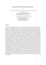
Por tal motivo, os acetatos, <strong>de</strong>vem seguir as normas estabelecidas pelo<br />
Manual <strong>de</strong> Harmonização <strong>de</strong> Imagem do IST.<br />
A figura junta mostra o aspecto geral (e informações úteis) do layout a usar<br />
para as apresentações referentes ao Instituto Superior Técnico.<br />
80<br />
68<br />
59<br />
25<br />
25<br />
INSTITUTO<br />
SUPERIOR<br />
TÉCNICO<br />
Secção<br />
<strong>de</strong> Sistemas<br />
140<br />
Título<br />
Sub-título<br />
Área para introdução (preferencial) <strong>de</strong> textos e<br />
imagens em letra tipo Times, com títulos em Gill<br />
Sans ou Arial, tamanho suficiente para permitir a<br />
leitura.<br />
Os textos <strong>de</strong>vem ser alinhados à esquerda.<br />
Figura 4 – Layout recomendado para acetatos<br />
Rui Loureiro - 2004 Projecto <strong>de</strong> <strong>Fim</strong> <strong>de</strong> <strong>Curso</strong><br />
25<br />
Os títulos (36pt.,<br />
negrito) e os subtítulos<br />
(24pt., simples), são<br />
grafados em letra tipo<br />
Gill Sans ou Arial, letras<br />
maiúsculas e<br />
minúsculas, alinhados à<br />
esquerda.<br />
O nome da Secção <strong>de</strong><br />
Sistemas é impresso a<br />
azul escuro, Pantone<br />
287, conforme a<br />
ilustração, a 11pt.,<br />
negrito, em letra tipo Gill<br />
Sans ou Arial, letras<br />
maiúsculas e<br />
minúsculas, alinhado à<br />
esquerda.
IST - DEM – Secção <strong>de</strong> Sistemas Normas <strong>de</strong> redacção e apresentação - 11<br />
4.2. ESTRUTURA<br />
A estrutura da apresentação com acetatos segue o esquema indicado pelas<br />
figuras. Em baixo à direita, entre parênteses rectos, sugere-se o número <strong>de</strong><br />
acetatos conveniente, para uma apresentação <strong>de</strong> 30 minutos.<br />
INSTITUTO<br />
SUPERIOR<br />
TÉCNICO<br />
Secção<br />
<strong>de</strong> Sistemas<br />
INSTITUTO<br />
SUPERIOR<br />
TÉCNICO<br />
Secção<br />
<strong>de</strong> Sistemas<br />
INSTITUTO<br />
SUPERIOR<br />
TÉCNICO<br />
Secção<br />
<strong>de</strong> Sistemas<br />
INSTITUTO<br />
SUPERIOR<br />
TÉCNICO<br />
Secção<br />
<strong>de</strong> Sistemas<br />
Título do Trabalho<br />
Nome do(s) autor(es)<br />
Nome do Apresentador<br />
Afiliação<br />
Trabalho orientado por: Prof. ….<br />
Introdução<br />
Justificação do tema do trabalho<br />
Enquadramento<br />
Objectivos<br />
Resultados<br />
(resumidamente)<br />
Gráficos<br />
Quadros comparativos<br />
Outras indicações necessárias<br />
Trabalho futuro<br />
Projectar o trabalho no futuro<br />
Como po<strong>de</strong> ser completado<br />
[1 acetato]<br />
Figura 5 – Acetatos <strong>de</strong> abertura<br />
[2 a 3 acetatos]<br />
[3 a 4 acetatos]<br />
Figura 6 – Acetatos <strong>de</strong> apresentação<br />
[1 acetato]<br />
Figura 7 – Acetatos <strong>de</strong> encerramento<br />
Rui Loureiro - 2004 Projecto <strong>de</strong> <strong>Fim</strong> <strong>de</strong> <strong>Curso</strong><br />
INSTITUTO<br />
SUPERIOR<br />
TÉCNICO<br />
Secção<br />
<strong>de</strong> Sistemas<br />
INSTITUTO<br />
SUPERIOR<br />
TÉCNICO<br />
Secção<br />
<strong>de</strong> Sistemas<br />
INSTITUTO<br />
SUPERIOR<br />
TÉCNICO<br />
Secção<br />
<strong>de</strong> Sistemas<br />
INSTITUTO<br />
SUPERIOR<br />
TÉCNICO<br />
Secção<br />
<strong>de</strong> Sistemas<br />
Agra<strong>de</strong>cimentos<br />
Agra<strong>de</strong>cimentos a pessoas e instituições.<br />
A existência <strong>de</strong> apoios financeiros é<br />
referida <strong>de</strong> forma nominativa.<br />
[1 acetato]<br />
Métodos e Técnicas<br />
(resumidamente)<br />
Como se realizou<br />
On<strong>de</strong> foi realizado<br />
O que se obteve<br />
Conclusões<br />
Que se obteve dos resultados<br />
Como enquadra o trabalho<br />
...<br />
Discussão<br />
(facultativo)<br />
[4 acetatos]<br />
[1 a 2 acetatos]<br />
Esta acetato final, <strong>de</strong>ve motivar a sessão<br />
<strong>de</strong> perguntas e respostas e manter-se<br />
exposto até ao seu encerramento.<br />
[1 acetato]
IST - DEM – Secção <strong>de</strong> Sistemas Normas <strong>de</strong> redacção e apresentação - 12<br />
4.3. OUTRAS INFORMAÇÕES<br />
A estrutura da apresentação po<strong>de</strong> variar, adaptando-se ao trabalho<br />
realizado.<br />
É dada gran<strong>de</strong> liberda<strong>de</strong> <strong>de</strong> concepção para os acetatos individuais, <strong>de</strong>s<strong>de</strong><br />
que as referências obrigatórias (logotipo do IST e indicação da secção)<br />
estejam presentes, para preservar a imagem da Instituição.<br />
Todos os acetatos <strong>de</strong>vem ser i<strong>de</strong>ntificados. Para além do primeiro, cuja<br />
função principal é a apresentação do trabalho e indicação da autoria, os<br />
restantes <strong>de</strong>vem sê-lo em rodapé. À esquerda o nome do(s) autor(es), a data<br />
e o local (opcional) on<strong>de</strong> se faz a apresentação. À direita, o título do trabalho<br />
e a paginação. Utilizar letra tipo Gill Sans ou Arial, 8/10 pt., letras maiúsculas<br />
e minúsculas.<br />
Alberto Moreno e Tiago Norte - Março 2004 - Lisboa Controlo <strong>de</strong> Processos por Visão - 12<br />
5. CARTAZES<br />
Figura 8 – I<strong>de</strong>ntificação dos acetatos em rodapé<br />
O cartaz (genericamente <strong>de</strong>signado por painel ou poster), é um dos<br />
elementos <strong>de</strong> avaliação da disciplina <strong>de</strong> Projecto <strong>de</strong> Sistemas I e II.<br />
Preten<strong>de</strong>-se que possam ser exibidos alguns dias antes das apresentações<br />
e que se mantenham em exposição, por toda a semana que se seguir.<br />
Servirão, também, para apresentação em eventos, que durante o ano lectivo<br />
seguinte tenham lugar. É uma forma <strong>de</strong> mostrar o que se produz, em termos<br />
científicos e <strong>de</strong> ensino no DEM e, mais especificamente, no Grupo <strong>de</strong><br />
Controlo Automação e Robótica.<br />
Um POSTER <strong>de</strong>ve ser :<br />
ATRACTIVO – mas contribuindo para veicular, <strong>de</strong> forma<br />
eficiente a mensagem cientifica.<br />
ORGANIZADO – o tema é focado <strong>de</strong> forma simples e<br />
posicionado em lugar <strong>de</strong> máxima<br />
visibilida<strong>de</strong>.<br />
DE FÁCIL LEITURA – estando colocado numa pare<strong>de</strong>, <strong>de</strong>ve<br />
permitir a leitura a uma distância mínima <strong>de</strong><br />
1,5 m.<br />
Não esquecer que a estrutura, organização, <strong>de</strong>sign, clareza e apresentação<br />
cuidada, são essenciais para o sucesso dum cartaz.<br />
Rui Loureiro - 2004 Projecto <strong>de</strong> <strong>Fim</strong> <strong>de</strong> <strong>Curso</strong>
IST - DEM – Secção <strong>de</strong> Sistemas Normas <strong>de</strong> redacção e apresentação - 13<br />
5.1. ESTRUTURA<br />
5.1.1. LÍNGUA<br />
Um poster, ainda que para apresentação interna, <strong>de</strong>ve, tal como os artigos<br />
científicos e os sumários, ser escrito em língua inglesa.<br />
5.1.2. DIMENSÕES<br />
Para garantir a normalização dimensional, com os cartazes utilizados por<br />
outras instituições, utiliza-se 100cm (altura) x 70 cm (largura).<br />
5.1.3. SUPORTE<br />
Para permitir a exposição suspensa, o cartaz <strong>de</strong>ve ter um suporte rígido.<br />
Utiliza-se, vulgarmente, K-line <strong>de</strong> 4/6 mm <strong>de</strong> espessura.<br />
5.1.4. LOGOTIPO DO IST<br />
Garantindo a imagem do IST, o logotipo <strong>de</strong>ve ser colocado no canto superior<br />
esquerdo do cartaz, com a indicação do <strong>Departamento</strong> (i.e. DEM), Instituto<br />
(i.e. IDMEC) ou secção (i.e. Secção <strong>de</strong> Sistemas), <strong>de</strong> acordo com as normas<br />
estabelecidas pelo Manual <strong>de</strong> Harmonização <strong>de</strong> Imagem.<br />
5.1.5. TÍTULO<br />
Com letras maiúsculas tipo Times New Roman (60-pt negrito). Não mais <strong>de</strong><br />
<strong>de</strong>z palavras. Centrado.<br />
5.1.6. AUTORES<br />
Inscritos sob o título, grafados a letra tipo Times New Roman (33-pt negrito)<br />
em maiúsculas e minúsculas. Utilizar uma única linha centrada.<br />
Apenas o nome próprio e o apelido, serão impressos por extenso. Uma<br />
inicial intermédia po<strong>de</strong>rá ser utilizada caso possa haver ambiguida<strong>de</strong>.<br />
5.1.7. FILIAÇÃO<br />
Em letra tipo Times New Roman (24-pt itálico) maiúsculas e minúsculas,<br />
centrado, <strong>de</strong>ve escrever-se o en<strong>de</strong>reço completo da instituição que acolhe os<br />
autores. Caso existam, os e-mail <strong>de</strong>stes <strong>de</strong>vem ser adicionados.<br />
5.1.8. RESUMO<br />
Título em letra tipo Times New Roman, 24-pt negrito, alinhado à esquerda.<br />
Texto em letra tipo Times New Roman <strong>de</strong> 24-pt, maiúsculas e minúsculas,<br />
justificado, com o máximo <strong>de</strong> 100 palavras.<br />
Con<strong>de</strong>nsado ao mínimo <strong>de</strong>ve incluir como e on<strong>de</strong> o trabalho foi realizado.<br />
5.1.9. BIBLIOGRAFIA<br />
Apenas as referências, directamente citadas no texto, são listadas<br />
alfabeticamente, pelo nome do primeiro autor. As regras <strong>de</strong> inscrição<br />
bibliográfica são idênticas às utilizadas nos artigos científicos.<br />
Rui Loureiro - 2004 Projecto <strong>de</strong> <strong>Fim</strong> <strong>de</strong> <strong>Curso</strong>
IST - DEM – Secção <strong>de</strong> Sistemas Normas <strong>de</strong> redacção e apresentação - 14<br />
Título em letra tipo Times New Roman, 24-pt negrito, maiúsculas, centrado.<br />
Restantes linhas <strong>de</strong>vem ser in<strong>de</strong>ntadas.<br />
5.1.10. CORPO<br />
O texto <strong>de</strong>ve ser impresso a duas colunas, sempre que possível, sem<br />
sacrificar a clareza da mensagem ou a imagem do cartaz.<br />
O tipo <strong>de</strong> letra a utilizar é <strong>de</strong>ixada à imaginação do autor(es). O tamanho <strong>de</strong><br />
24pt, maiúsculas e minúsculas, <strong>de</strong>ve ser escolhido para permitir a leitura a,<br />
no mínimo, 1,5 m.<br />
Os parágrafos são justificados, usam espaçamento a uma linha e não são<br />
in<strong>de</strong>ntados. Usa-se uma linha em branco para separar parágrafos.<br />
5.1.11. AGRADECIMENTOS<br />
Título em letra tipo Times New Roman, 24-pt negrito, maiúsculas, centrado.<br />
Corpo em letra tipo Times New Roman 18-pt, maiúsculas e minúsculas,<br />
centrado.<br />
5.2. CONTEÚDO<br />
5.2.1. INTRODUÇÃO<br />
Breve, referindo apenas os tópicos do trabalho realizado. A introdução não é<br />
um amontoado <strong>de</strong> teorias e equações. Po<strong>de</strong> utilizar frases curtas (bullet<br />
points).<br />
5.2.2. OBJECTIVOS<br />
Devem ser realçados e apresentados em frases curtas.<br />
5.2.3. TRABALHO REALIZADO<br />
Textos resumidos. Devem ser utilizados <strong>de</strong>senhos e esquemas.<br />
5.2.4. RESULTADOS<br />
Utilizar tabelas, figuras ou esquemas para apresentar os resultados obtidos<br />
experimentalmente.<br />
5.2.5. CONCLUSÕES<br />
Não <strong>de</strong>vem incluir discussão, apenas indicar as i<strong>de</strong>ias principais, a serem<br />
extraídas dos resultados encontrados.<br />
5.3. GRAFISMO<br />
5.3.1. FIGURAS<br />
Devem ser posicionadas o mais perto possível da referencia que lhe é feita<br />
no texto.<br />
As fotografias e figuras <strong>de</strong>vem ser coloridas, porém preparadas para<br />
impressão em níveis <strong>de</strong> cinzento.<br />
Rui Loureiro - 2004 Projecto <strong>de</strong> <strong>Fim</strong> <strong>de</strong> <strong>Curso</strong>
IST - DEM – Secção <strong>de</strong> Sistemas Normas <strong>de</strong> redacção e apresentação - 15<br />
5.3.2. TABELAS<br />
Não se utilizam linhas verticais para<br />
separar as colunas, apenas as linhas<br />
horizontais <strong>de</strong> separação das entradas.<br />
O título <strong>de</strong>ve ser sublinhado e utilizar<br />
letras do tipo Times New Roman <strong>de</strong> 18-pt,<br />
maiúsculas e minúsculas, centrado.<br />
6. APRESENTAÇÕES ORAIS<br />
Uma prova pública, apesar <strong>de</strong> interna, é realizada em ambiente<br />
relativamente formal. Trajar, pois, <strong>de</strong> acordo com a ocasião.<br />
Deve falar-se claramente, <strong>de</strong>vagar, em voz alta (para garantir a audição<br />
sobre o ruído <strong>de</strong> fundo dos ouvintes) e olhando directamente para a<br />
audiência. O recurso a notas escritas <strong>de</strong>ve ser o mais reduzido possível.<br />
Não ultrapassar o tempo atribuído à apresentação. Ter-se-à oportunida<strong>de</strong>,<br />
na sessão <strong>de</strong> perguntas e respostas, <strong>de</strong> voltar aos temas que tenham ficado<br />
menos explícitos na apresentação.<br />
O poster po<strong>de</strong> ser utilizado como apoio à sessão <strong>de</strong> perguntas e respostas.<br />
Deve, por isso, distribuir-se, pela audiência, uma cópia (A4) a preto e branco.<br />
Também o resumo do trabalho <strong>de</strong>ve estar disponível à assistência.<br />
Durante a sessão <strong>de</strong> perguntas e respostas, <strong>de</strong>ve analisar-se as perguntas<br />
recebidas e dar respostas curtas, concisas e objectivas, mas em perfeita<br />
ligação com a comunicação efectuada. Não sustentar discussões<br />
discordantes. Neste caso convidar o interlocutor para uma conversa no fim<br />
dos trabalhos.<br />
7. CITAÇÕES E REFERÊNCIAS BIBLIOGRÁFICAS<br />
A forma <strong>de</strong> registar as referências <strong>de</strong>pen<strong>de</strong> do estilo da publicação e das<br />
suas regras, <strong>de</strong>vendo ser seguidas no mais ínfimo pormenor.<br />
Indicam-se, seguidamente, as regras para citações e referências<br />
bibliográficas a utilizar nos trabalhos das disciplinas leccionadas pelo Grupo<br />
<strong>de</strong> Controlo Automação e Robótica, nomeadamente Projecto <strong>de</strong> Sistemas I e<br />
II e Controlo Integrado da Produção, que seguirão o SISTEMA HARVARD<br />
(também <strong>de</strong>signado por Sistema Nome-e-Ano).<br />
7.1. SISTEMA HARVARD<br />
Table heading un<strong>de</strong>rlined and centred<br />
Xxxx Xxxx Xxxx Xxxx<br />
X X XX<br />
XXX X XX XX<br />
X XXX XX XXX<br />
Na secção <strong>de</strong> Bibliografia, a listagem dos autores <strong>de</strong>ve ser feita por or<strong>de</strong>m<br />
alfabética. Quando o autor, possui várias publicação referidas, estas serão<br />
inscritas por or<strong>de</strong>m cronológica. Se inscrever mais do que uma publicação,<br />
do mesmo autor e ano, <strong>de</strong>ve distinguir as referências por letras minúsculas a,<br />
b, c, etc.<br />
Exemplos:<br />
ABREU, R. (2003), …<br />
BAKER, Gold (1998), …<br />
BAKER, Richard (2000), …<br />
CARVALHO, H. (1999), …<br />
Rui Loureiro - 2004 Projecto <strong>de</strong> <strong>Fim</strong> <strong>de</strong> <strong>Curso</strong>
IST - DEM – Secção <strong>de</strong> Sistemas Normas <strong>de</strong> redacção e apresentação - 16<br />
CARVALHO, H. (2001), …<br />
ESTRELA, E., SOARES, M.A., e LEITÃO, M. J, (2003), …<br />
MADEIRA, A.C. e ABREU, M.M., (2004), …<br />
RICARDO, D. (2003a), …<br />
RICARDO, D. (2003b), …<br />
RICARDO, D. (2003c), …<br />
A vantagem <strong>de</strong> se adoptar este sistema, em relação a outros (i.e. Vancouver,<br />
que utiliza numeração sequencial), é o po<strong>de</strong>r-se adicionar ou apagar citações<br />
ou referencias dos textos, sem alterar a secção Bibliográfica. Há, também,<br />
uma imediata i<strong>de</strong>ntificação das referências.<br />
7.2. CITAÇÕES NO TEXTO<br />
Ao citar uma referência, <strong>de</strong>ve indicar o nome do autor e o ano da publicação.<br />
Se citar mais do que uma publicação, do mesmo autor e ano, <strong>de</strong>ve distinguir<br />
as referências, adicionando ao ano letras minúsculas. Publicações com dois<br />
autores, <strong>de</strong>vem ser indicadas com ambos os nomes seguidos do ano. Se as<br />
referências tiverem mais do que dois autores, será indicado apenas o nome<br />
do primeiro autor seguido <strong>de</strong> et al.<br />
Exemplos:<br />
Ricardo (2003b) apresentou …<br />
De acordo com Ma<strong>de</strong>ira e Abreu (2004), concluímos….<br />
Tal como <strong>de</strong>scrito (Estrela et al.,2003), sugere-se …<br />
7.3. REGRAS DE LISTAGEM BIBLIOGRÁFICA<br />
Há diversas regras sobre a forma como as citações feitas no texto <strong>de</strong>vem ser<br />
listadas na Bibliografia. A inscrição <strong>de</strong>pen<strong>de</strong> do tipo <strong>de</strong> publicação.<br />
Listam-se, seguidamente, os esquemas <strong>de</strong> inscrição que <strong>de</strong>ve utilizar.<br />
7.3.1. ARTIGOS<br />
Autor(es) (apelido por extenso [virgula], inicial do nome próprio [ponto]<br />
separação entre autores feito por virgula) [espaço] Ano da publicação (entre<br />
parênteses) [vírgula] Título do artigo [virgula] Nome da publicação (em<br />
itálico) [espaço] número do volume (em negrito) [dois pontos] páginas<br />
referidas [ponto].<br />
Exemplo:<br />
Charlie, P. (1985b), Controlling by Remote Sensing, Journal of Process<br />
Control 66:125-131.<br />
7.3.2. CAPÍTULOS DE LIVROS<br />
Autor(es) (apelido por extenso [virgula], inicial do nome próprio [ponto]<br />
separação entre autores feito por virgula. Utilização do separador [e] para o<br />
último autor) [espaço] Ano da publicação (entre parênteses) [vírgula] Título<br />
do capítulo [ponto] [In] Título do livro (em itálico) [virgula] Nome(s) do<br />
editor(es) [ed(s).] [vírgula] [pp.] páginas referidas [ponto] Entida<strong>de</strong> editora<br />
[vírgula] Local (cida<strong>de</strong>) [vírgula] e país <strong>de</strong> publicação (siglas) [ponto]<br />
Rui Loureiro - 2004 Projecto <strong>de</strong> <strong>Fim</strong> <strong>de</strong> <strong>Curso</strong>
IST - DEM – Secção <strong>de</strong> Sistemas Normas <strong>de</strong> redacção e apresentação - 17<br />
Exemplo:<br />
MADEIRA, A. e CARDEIRA, M. (1954), Referências Bibliográficas. In<br />
Comunicar e redigir trabalhos científicos, R. Dias (ed.), pp. 53-58. Aca<strong>de</strong>mia,<br />
Lisboa, PT.<br />
7.3.3. LIVROS<br />
Autor(es) (apelido por extenso [virgula], inicial do nome próprio [ponto]<br />
separação entre autores feito por virgula. Utilização do separador [e] para o<br />
último autor) [espaço] Ano da publicação (entre parênteses) [vírgula] Título<br />
do livro (em itálico) [ponto] Entida<strong>de</strong> editora [vírgula] Local (cida<strong>de</strong>) [vírgula]<br />
e país <strong>de</strong> publicação (siglas) [ponto] Número total <strong>de</strong> páginas [pp.]<br />
Exemplo:<br />
MADEIRA, A. e CARDEIRA, M. (1954),Comunicar e redigir trabalhos<br />
científicos. Aca<strong>de</strong>mia, Lisboa, PT. 155 pp.<br />
7.3.4. ACTAS DE CONFERÊNCIAS<br />
Autor(es) (apelido por extenso [virgula], inicial do nome próprio [ponto]<br />
separação entre autores feito por virgula. Utilização do separador [e] para o<br />
último autor) [espaço] Ano da publicação (entre parênteses) [vírgula] Título<br />
do trabalho [ponto] [Actas da Conferência (ou Proceedings of)] Nome da<br />
conferência (em itálico) [virgula] Nome(s) do editor(es) [ed(s).] [vírgula] Local<br />
(cida<strong>de</strong>) [vírgula] e país (siglas) on<strong>de</strong> foi realizada a Conferência [ponto] [pp.]<br />
páginas referidas [ponto]<br />
Exemplo:<br />
Pereira, A. et al.(2000), Remote Control in Industrial Processes. Proceedings of<br />
Industrial Processes’2007: 9th Portuguese Conference on Remote Control,<br />
Barrera, C. (ed.), Castelo Branco, PT. pp. 4-6.<br />
7.3.5. DISSERTAÇÕES E TESES<br />
Autor (apelido por extenso [virgula], inicial do nome próprio [ponto]) [espaço]<br />
Ano <strong>de</strong> apresentação (entre parênteses) [vírgula] Título completo do trabalho<br />
(em itálico - incluindo subtítulos se existir) [ponto] Grau (Tese <strong>de</strong><br />
Doutoramento, Dissertação <strong>de</strong> Mestrado) [ponto] Instituição [vírgula] e Local<br />
(cida<strong>de</strong>) [vírgula] e país on<strong>de</strong> foi apresentada [ponto] número <strong>de</strong> páginas<br />
[pp.]<br />
Exemplo:<br />
Kong, X. (1999), Incorporating Landscape Pattern Features in a Spatial<br />
Harvest Mo<strong>de</strong>l. Ph.D. Thesis. University of British Columbia. Vancouver,<br />
CAN. 121 pp.<br />
7.3.6. INTERNET<br />
A Internet é um meio <strong>de</strong> pesquisa bibliográfica importante, logo não po<strong>de</strong> ser<br />
esquecida como forma <strong>de</strong> consulta em trabalhos científicos. Porém, sendo<br />
um ambiente extremamente dinâmico, os en<strong>de</strong>reços, on<strong>de</strong> se encontram os<br />
Rui Loureiro - 2004 Projecto <strong>de</strong> <strong>Fim</strong> <strong>de</strong> <strong>Curso</strong>
IST - DEM – Secção <strong>de</strong> Sistemas Normas <strong>de</strong> redacção e apresentação - 18<br />
trabalhos a referenciar, <strong>de</strong>sactualizam-se rapidamente. Por este motivo, a<br />
Bibliografia, obtida por pesquisa na Internet, só <strong>de</strong>ve ser utilizada quando<br />
não se teve acesso a versões impressas, caso contrário <strong>de</strong>vem ser estas as<br />
referidas.<br />
a) Artigos científicos on line:<br />
Autor(es) (apelido por extenso [virgula], inicial do nome próprio [ponto]<br />
separação entre autores feito por virgula) [espaço] Data do documento –se<br />
existir - (entre parênteses) [vírgula] Título do trabalho [virgula] Título da<br />
publicação (em itálico) [espaço] número do volume (em negrito) [dois<br />
pontos] páginas referidas [ponto] [Disponível em: ]<br />
[ponto] [Acesso em:] [ponto]<br />
b) Homepage:<br />
Autor(es) (apelido por extenso [virgula], inicial do nome próprio [ponto]<br />
separação entre autores feito por virgula) [espaço] Título [ponto] Informações<br />
complementares [ponto] [Disponível em: ] [ponto] [Acesso<br />
em:] [ponto]<br />
8. ANEXOS<br />
Os exemplos que se juntam, ainda que não sigam exactamente as regras<br />
<strong>de</strong>finidas por estas normas, o que não será possível nos trabalhos a realizar<br />
futuramente, mostram, <strong>de</strong> uma forma geral, o modo como se <strong>de</strong>vem<br />
apresentar, quer posters quer papers.<br />
PAPER 1<br />
PAPER 2<br />
PAPER 3<br />
AUTOMATIC CREATION OF SIMULATION MODELS FOR FLOW<br />
ASSEMBLY LINES<br />
WEB BASED SUPERVISION OF REMOTE UNITS<br />
INDUSTRIAL SENSORS FOR GUIDING AN AUTONOMOUS VEHICLE<br />
Rui Loureiro - 2004 Projecto <strong>de</strong> <strong>Fim</strong> <strong>de</strong> <strong>Curso</strong>
IST - DEM – Secção <strong>de</strong> Sistemas Normas <strong>de</strong> redacção e apresentação - 19<br />
POSTER<br />
IDMEC<br />
FPIAA (Find Persons in Atlas Areas)<br />
Abstract: The main objective of this system is to find persons insi<strong>de</strong> the ATLAS area, in case of<br />
acci<strong>de</strong>nt, or if someone is still insi<strong>de</strong> when an experiment is about to begin. As such, both software<br />
and hardware issues must be resolved. ATLAS presents a unique working environment, both in<br />
environment and in requirements.<br />
In the hardware issue, only the solution based on volumetric ultrasonic sensors appears to be feasible,<br />
due to restrictions with other volumetric sensors and high cost of non-volumetric alternatives. A field<br />
bus will connect these sensors to a computer to process the data.<br />
Also software will be <strong>de</strong>veloped to process hardware input, visualization and alarm generation.<br />
The prototype has the following abilities :<br />
• Detect position of persons as indicated by volumetric sensors;<br />
• Generate alarms when a person disappears. That happens when sensors are <strong>de</strong>tecting<br />
someone, and sud<strong>de</strong>nly both that sensor and nearby sensors stop <strong>de</strong>tecting for a given amount<br />
of time. That could signal a problem with that person.<br />
This is a viability study. As such, it’s unclear whether a useful system can be produced, and if so,<br />
whether it can be produced within budget. This is due to the fact that the environment and<br />
requirements are unique.<br />
Carlos Car<strong>de</strong>ira 1 , Amélia Maio 2 , Gianpaolo Benicasa 3<br />
1<br />
Instituto Superior Técnico, Technical University of Lisbon<br />
Mechanical Engineering Department, IDMEC-GCAR<br />
Av. Rovisco Pais, 1049-001 Lisboa, Portugal<br />
e-mail: {xxx, yyyyy, zzzzz}@<strong>de</strong>m.ist.utl.pt<br />
2<br />
LIP Lisboa<br />
Av. Elias Garcia 14, 1º 1000-149 Lisboa, Portugal<br />
e-mail: ameliamaio@werkygtdr.pt<br />
3<br />
CERN<br />
CH-1211 Genève 23 Switzerland<br />
e-mail: g.benicasa@sw.d<strong>de</strong>uvgft.com<br />
BIBLIOGRAPHY<br />
Atlas Technical Design Report, Cern Report Number ATLAS-TL13, January 1999<br />
G. Benicasa, “Equipment fault report and safety: a proposition”, EDMS:ATC-TY-EN-0001<br />
ACKNOWLEDGEMENT<br />
This research is partially financed by the FCT through the program POCTI - Unida<strong>de</strong> 46 - Linha 3,<br />
subsidized by FEDER.<br />
This work was partly supported by CERN (IDMEC grant nº PL208).<br />
This proposal addresses CERN’s person surveillance needs insi<strong>de</strong> the<br />
ATLAS area.<br />
During the maintenance periods, tens of specialists enter the cavern<br />
where the system is located for verifications and repair work. The<br />
specialists need to enter the ATLAS itself and other exiguous areas not<br />
visible from the outsi<strong>de</strong>. Sometimes it is even necessary to crawl some<br />
distance to the area of interest. The topology of the working environment<br />
is complex making very difficult the work of rescue teams in case of<br />
acci<strong>de</strong>nts such as fire or cryogenic liquid spills.<br />
The need to know where people are is essential to prevent fatal<br />
consequences if any acci<strong>de</strong>nt ever occurs.<br />
This work proposes the study and implementation of a prototype of a<br />
data acquisition system that can remotely show the positions of persons<br />
in the monitored areas. This prototype if successful in a controlled<br />
environment can be tested in the ATLAS environment so that a<br />
production system can be <strong>de</strong>signed.<br />
Architecture overview<br />
Each volumetric sensor is connected to the computer hosting the monitoring software. The prototype has only a limited number of sensors connected only to show the<br />
concept. The monitoring software picks up the signals sent from the sensors, and displays them in a graphical interface showing the physical space occupied by the monitoring<br />
system. The software keeps track of incoming signals and remembers them in or<strong>de</strong>r to activate alarm signals to the operator when a contact is lost. The notion of a lost contact<br />
is a time-out on a signal.<br />
Software<br />
The monitoring application displays graphically the monitored area. This area is organized by no<strong>de</strong>s, each one being a monitored zone. Each zone corresponds to a sensor. When<br />
a signal is being received from that zone the application shows a person icon over the no<strong>de</strong>.<br />
The application generates alarms when a given contact is not followed by another contact either in the same zone or any adjacent navigable zone, in a given amount of time.<br />
The software takes an optimistic approach. If a contact is lost before the timeout and another adjacent contact overlaps the first, no alarm is generated. It is assumed that the<br />
second contact is responsible for giving out the alarm if the first one corresponds to an injured person.<br />
The mo<strong>de</strong>l of the hypothetical area to be monitored will be simple enough to fit in a normal <strong>de</strong>sktop computer screen.<br />
sensor<br />
sensor<br />
sensor<br />
sensor<br />
Rui Loureiro - 2004 Projecto <strong>de</strong> <strong>Fim</strong> <strong>de</strong> <strong>Curso</strong><br />
sensor<br />
sensor<br />
Workstation
IST - DEM – Secção <strong>de</strong> Sistemas Normas <strong>de</strong> redacção e apresentação - 20<br />
BIBLIOGRAFIA<br />
ESTRELA, E., SOARES, M.A., e LEITÃO, M. J. (2003), Saber Escrever Saber Falar:<br />
Um guia completo para usar correctamente a língua portuguesa, Dom Quixote,<br />
Lisboa.<br />
MADEIRA, A.C. e ABREU, M.M. (2004), Comunicar em Ciência: como redigir e<br />
apresentar trabalhos científicos, Escolar Editora, Lisboa.<br />
RICARDO, D. (2003), AINDA BEM QUE ME PERGUNTA: manual <strong>de</strong> escrita<br />
jornalística, Editorial Notícias, Lisboa.<br />
WILSON, A. (org.) (2001), MANUAL DE COMUNICAÇÃO EM CIÊNCIA: Como transmitir<br />
num minuto ou numa página o trabalho <strong>de</strong> anos, Tradução <strong>de</strong> Tânia Rocha,<br />
Editorial Replicação, Lisboa.<br />
Rui Loureiro - 2004 Projecto <strong>de</strong> <strong>Fim</strong> <strong>de</strong> <strong>Curso</strong>
AUTOMATIC CREATION OF SIMULATION MODELS FOR FLOW ASSEMBLY<br />
LINES<br />
João Weinholtz†, Rui Loureiro‡, Carlos Car<strong>de</strong>ira†, João M. Sousa†<br />
†Instituto Superior Técnico, Technical University of Lisbon<br />
Dept. of Mechanical Engineering, GCAR - IDMEC<br />
Av. Rovisco Pais, 1049-001 Lisboa, Portugal<br />
joao.weinholtz@netcabo.pt, {carlos.car<strong>de</strong>ira, jmsousa}@ist.utl.pt<br />
‡Bombardier Transportation Portugal, SA<br />
Rua Vice-Almirante Azevedo Coutinho , nº 1, 2700-843 Amadora, Portugal<br />
rui.loureiro@pt.transport.bombardier.com<br />
Abstract: This paper presents a new software tool for automatic creation of simulation<br />
mo<strong>de</strong>ls for flow lines. The tool was <strong>de</strong>veloped in a general way. The tool was applied to the<br />
production flow line at the rolling stock Company Bombardier Transportation Portugal, SA,<br />
in Amadora, in or<strong>de</strong>r to <strong>de</strong>velop its simulation mo<strong>de</strong>l. Information regarding manufacturing<br />
philosophies, flow assembly lines, production scheduling, and software tools for the mo<strong>de</strong>l<br />
creation are required to perform this task. The paper mainly focuses on the mo<strong>de</strong>l creation<br />
process and the productivity gains generated by this work. Copyright © 2004 IFAC<br />
Keywords: Process simulators, production systems, scheduling, simulation.<br />
1. INTRODUCTION<br />
New manufacturing philosophies points to production as<br />
the central area of the manufacturing process. Note that<br />
production is supported by many other service functions<br />
in or<strong>de</strong>r to timely <strong>de</strong>liver high-quality, low-cost,<br />
functional products to customers, see Pinedo (2002). The<br />
major concerns of the or<strong>de</strong>r/project management are then<br />
process organization, resource optimization and<br />
throughput time reduction according to vision and<br />
objectives of the company.<br />
The dynamic strategies of corporations, especially the<br />
ones that have to lead with long lead-time products, are<br />
<strong>de</strong>aling with a strong increase of management<br />
complexity, since processes and information must be<br />
adjusted quickly and consistently. Currently, these<br />
adjustments to changes have not been done in an<br />
efficient way; the costs of changes are usually high.<br />
Therefore, the low adaptation of enterprises to the<br />
constraints of the market resources is not allowing the<br />
optimization of processes and is <strong>de</strong>grading production<br />
costs.<br />
Several software solutions are commercially available to<br />
this optimization, but they normally are focused on the<br />
sequence generation and/or line balancing, disregarding<br />
the optimization of production processes and the<br />
dynamism of the companies.<br />
Due to the high costs associated with the revision of a<br />
manufacturing process (a methods team would spend<br />
weeks or months to re<strong>de</strong>sign a running process and the<br />
double of the time to issue all required documentation)<br />
process optimization is only verified once – in the initial<br />
phase of layout <strong>de</strong>sign and aggregate documentation.<br />
Thus, the optimization process is done by local subprocess<br />
improvement with the goal of reducing the<br />
execution time of individual tasks, ignoring completely<br />
the dynamic philosophies linked with company main<br />
lines.<br />
In or<strong>de</strong>r to achieve optimized solutions at reduced cost, it<br />
is imperative to <strong>de</strong>velop algorithms to be implemented in<br />
some standard software.<br />
This paper presents the <strong>de</strong>velopment of software tools to<br />
simulate and optimize flow assembly lines. The<br />
presented tool allows the inclusion of methods staff<br />
expertise. This know-how allows a fast dynamic<br />
reconfiguration of the assembly scheduling, a fast<br />
response to shortages in assembly line or equipment
malfunctions and an efficient adaptation to changes in<br />
the company objectives.<br />
The study of flow production lines is a very complex task<br />
due mainly to the huge number of variables to handle<br />
(Pinedo and Chao, 1999). The <strong>de</strong>veloped work started by<br />
analyzing an existing production line. A <strong>de</strong>ep and<br />
continuous communication with the methods team was<br />
required for acquiring data and learning in <strong>de</strong>tail the<br />
implementation of the production line.<br />
The key point in a flow assembly line is the production<br />
schedule. The scheduling solutions for production were<br />
optimized based on standard techniques, namely the<br />
Shifting Bottleneck Heuristic (Pinedo, 2002). These<br />
solutions were <strong>de</strong>veloped recurring to the software<br />
MatLab. The obtained scheduling is stored in a database<br />
and becomes the input necessary for the mo<strong>de</strong>l creation.<br />
These data is translated to Arena using Visual Basic, to<br />
simulate, validate and test the obtained production<br />
simulation mo<strong>de</strong>ls. Note that the work is general enough,<br />
such that the <strong>de</strong>veloped mo<strong>de</strong>ls can simulate different<br />
types of large-scale products, such as rolling stock<br />
material, planes or armored vehicles.<br />
Classically, simulations mo<strong>de</strong>ls are built to represent the<br />
reality. As so, the i<strong>de</strong>al mo<strong>de</strong>l should allow the<br />
simulation of unforeseen difficulties and adapt itself to<br />
new environments. A simulation, beyond representing<br />
the reality, can also be used to study the mo<strong>de</strong>l responses<br />
to chosen sequences of events. The main goals of the<br />
<strong>de</strong>veloped work were then to obtain a solution for the<br />
scheduling problem and to <strong>de</strong>fine the risk of the solutions<br />
found. To achieve these objectives the following steps<br />
were performed:<br />
1. Analysis of flow assembly lines and i<strong>de</strong>ntification of<br />
their constraints.<br />
2. Definition of a data structure to store the production<br />
schedule for simulation purposes.<br />
3. Development of a software tool for automatic<br />
creation of simulation mo<strong>de</strong>ls of a given production<br />
schedule.<br />
4. Application to the flow assembly line of the train<br />
manufacturing process implemented at Bombardier<br />
Transportation SA – Amadora.<br />
5. Analysis of obtained results.<br />
This article is organized as follows. Section 2 presents<br />
some software simulation tools and the reasons to choose<br />
a special one. Section 3 <strong>de</strong>scribes the characteristics of<br />
the <strong>de</strong>veloped software tool, presenting both the objects<br />
of the tool and the flow assembly lines specifications and<br />
special characteristics. The <strong>de</strong>tailed <strong>de</strong>scription of the<br />
<strong>de</strong>veloped software tool and the justification for some<br />
options that were ma<strong>de</strong> are presented in Section 4. A<br />
case study and its production scheduling are <strong>de</strong>scribed in<br />
section 5, and some conclusions are drawn in section 6.<br />
2. SOFTWARE SIMULATION TOOLS<br />
The simulation of industrial assembly lines has been<br />
done by different methodologies, especially by those that<br />
are computer ai<strong>de</strong>d. Different software tools can be<br />
found for discrete or continuous event systems exist.<br />
Due to the industrial focus of simulation software<br />
houses, some difficulties arise in finding information<br />
about the features of commercial available tools.<br />
Hssain (2000) presents some solutions to flux simulation.<br />
Moreover, there are different software simulation and<br />
scheduling tools available like Arena (Kelton et al.,<br />
2003), Witness, Automod, Asprova, or Jobboss, for<br />
which their features were summarily studied. Russo and<br />
Vicente (2003) performed a comparative study of those<br />
software tools based on learning easiness, process<br />
adaptation, graphic features and cost aspects, as<br />
presented in Table 1.<br />
Table 1: Software tools comparison<br />
learning<br />
easiness<br />
process<br />
adaptation<br />
continuos<br />
process<br />
graphic<br />
features<br />
cost<br />
ARENA D A C A C<br />
AUTOMOD C A C A D<br />
EXTEND B B A B A<br />
PROMODEL B B D B D<br />
SIMPLE ++ C C D C E<br />
TAYLOR B C D B B<br />
WITNESS C A C B D<br />
The characteristics that are more relevant for the<br />
presented work are process adaptation and the<br />
visualization facility translated in the graphic features.<br />
By observing Table 1, it is easily conclu<strong>de</strong>d that both<br />
Arena and Automod are suitable to the simulation<br />
purposes of this paper. As Arena is less expensive, and<br />
moreover a license un<strong>de</strong>r special conditions for research<br />
and <strong>de</strong>velopment was possible to be bought, it was the<br />
software chosen for simulation of the production line.<br />
3. CHARACTERISTICS OF THE SOFTWARE TOOL<br />
This section presents the <strong>de</strong>scription of the basic<br />
features, in terms of functional characteristics to allow<br />
the <strong>de</strong>velopment of simulation mo<strong>de</strong>ls.<br />
3.1 Objects of the software tool<br />
The objects of the software <strong>de</strong>velopment tool are the<br />
following.
Entities – are the dynamic objects for simulation.<br />
They can be created, used through the system and<br />
<strong>de</strong>leted when they no longer necessary for the<br />
simulation. They are abstract representations of the<br />
objects to be processed in the system.<br />
Attributes – are each characteristic of an entity. An<br />
entity can contain several different characteristics at<br />
same time.<br />
Variables – are <strong>de</strong>fined as global for a specific<br />
system, and have read/write access by all the<br />
entities.<br />
Resources – represent any need, such as a worker, a<br />
machine, etc. of a task. The resources have limited<br />
capacity, can be used in any section of the mo<strong>de</strong>l<br />
and can be used by any entity.<br />
Queues – are entities that request a resource in use<br />
by other entity. The entities must wait in the queue<br />
until the resource is released.<br />
Arena<br />
Macros<br />
Visual<br />
Basic<br />
Automatic creation of<br />
simulation mo<strong>de</strong>l<br />
Macros<br />
Fig. 1: Creation of the simulation mo<strong>de</strong>l.<br />
In or<strong>de</strong>r to build a simulation mo<strong>de</strong>l automatically it is<br />
necessary to make the connection between a production<br />
schedule using the Shifting Bottleneck Heuristic (stored<br />
in Excel) and Arena. The communication is established<br />
using a Visual Basic program, which receives the<br />
necessary information and creates the simulation of the<br />
production line in Arena.<br />
3.2 Specifications and special characteristics<br />
During the process analysis important constraints were<br />
taken into account:<br />
Working stations may share resources<br />
Tasks may have pre<strong>de</strong>cessors<br />
Assembly lines have the ability to produce vehicles<br />
of different types<br />
Different tasks can be executed simultaneously in<br />
the same working station, but at different locations<br />
Task assembly times follow a probabilistic<br />
distribution<br />
Task times can have large variations.<br />
These specifications were all implemented in the<br />
software tool to create simulation tools. It should be<br />
stressed that he cooperation of workers and production<br />
experts was fundamental for the <strong>de</strong>termination of the<br />
characteristics of the assembly line and their respective<br />
constraints.<br />
4. SOFTWARE TOOL FOR MODEL CREATION<br />
The software tool <strong>de</strong>veloped for the simulation of<br />
production lines is at the moment implemented for<br />
Flexible Flow Shop configurations (Pinedo, 2002). Any<br />
production schedule can be mo<strong>de</strong>led and simulated by<br />
Arena using the <strong>de</strong>veloped tool.<br />
The mo<strong>de</strong>l manages all the existing resources and tasks,<br />
creating sequences and attributes characteristics to them.<br />
Each task can be <strong>de</strong>scribed as in<strong>de</strong>pen<strong>de</strong>nt, i.e., it does<br />
not need to follow a sequence, and can be part of<br />
different sequences. Several variables must be created,<br />
namely: vehicle type, vehicle type comparison, station<br />
occupation control and task execution i<strong>de</strong>ntification. The<br />
software tool also creates the processing mo<strong>de</strong>ls<br />
<strong>de</strong>scribed next.<br />
4.1 Entity creation<br />
Each entity represents a “vehicle”, which receives all<br />
tasks and resources required, and transport them until the<br />
end of the manufacturing process. The entity must follow<br />
the tasks <strong>de</strong>fined in the production schedule, which are<br />
accomplished in the given station. At any instant the<br />
entity must contain the work in progress of the process.<br />
This module <strong>de</strong>termines also the first stations of the<br />
routing to be followed by the entity, holding it in case the<br />
<strong>de</strong>stination station is not free. An example of the Arena<br />
aspect of an entity is given in Fig. 2.<br />
Fig. 2: Entity creation and routing indication.<br />
4.2 Start of an assembly station<br />
Assembly stations are in<strong>de</strong>pen<strong>de</strong>nt amongst them. These<br />
stations transform the arriving entity and process it. The
entity type is verified and routed to the task sequence<br />
<strong>de</strong>fined for the station. The number of teams and its<br />
location in the station are <strong>de</strong>fined and inclu<strong>de</strong>d into the<br />
entity. Also task works are attributed to the entity. The<br />
assembly station can receive different kinds of entities<br />
and processes them sequentially. An example of an<br />
assembly station is given in Fig. 3.<br />
Fig. 3: Example of an assembly station with 4 types of<br />
entities to process.<br />
4.3 Tasks<br />
The objective of a task is to use the respective resources<br />
taking a certain time according to its requirements. Some<br />
tasks may be <strong>de</strong>pen<strong>de</strong>nt of others (prece<strong>de</strong>nts) to be<br />
initialized. Only the prece<strong>de</strong>nt tasks processed in the<br />
same station are verified before the initialization of a<br />
task.<br />
When an entity arrives at a certain task, the availability<br />
of resources must be verified. If the resources are not<br />
available, the entity is retained until they are at disposal.<br />
The resources are retained by that task during a certain<br />
time, and are released when this time elapses. After the<br />
task conclusion, the entity is routed to the next task or to<br />
the end of the station. The task formation in Arena is<br />
shown in Fig. 4.<br />
Fig. 4: Task formation.<br />
4.4 Closing of the assembly station<br />
When an assembly station is closing, the leaving entities<br />
represent an assembled product or part of it.<br />
This module is used to aggregate all assembled parts of<br />
the product in just one entity that represents all work in<br />
process incorporated in the tasks processed before. This<br />
last entity is then routed to the end of the module, where<br />
is retained until the next station is available to receive it.<br />
Transport of entities between stations is ma<strong>de</strong> by a single<br />
resource. If the transportation means are not available,<br />
the entity remains at the end of the station waiting for its<br />
availability.<br />
Each closing assembly station can concatenate up to 25<br />
teams (processes) into one single entity. Is also in this<br />
module that some statistical data can be stored for later<br />
analysis. An example is given in Fig. 5.<br />
Fig. 5: Example of a closing assembly station module<br />
concatenating 2 teams.<br />
4.5 End module<br />
After an entity had passed through all assembly stations<br />
it is routed to the end module (were its throughput time is<br />
computed) and disposed, see Fig. 6.<br />
Fig. 6: Process ending module.<br />
5. CASE STUDY<br />
In this paper, the case study for software validation is the<br />
production line of rolling stock vehicles of the CP2000<br />
type, manufactured at Bombardier Transportation<br />
Portugal SA, Amadora. The flow assembly line is<br />
producing a train of four different vehicles, as shown in<br />
Fig. 8.
Fig. 8: The CP2000 train formation.<br />
5.1 The CP2000 assembly line<br />
The assembly line is unique and processes all vehicles<br />
simultaneously at the same bit-rate. Each vehicle has its<br />
own assembly tasks but the assembly line responds well<br />
to the different solicitations. Eight workstations, with<br />
four locations each, form the flow assembly line to built<br />
the train, see Fig. 9.<br />
Entrada<br />
Saída<br />
Pré-Montagem<br />
Bogies<br />
Estação 650<br />
EA<br />
Estação 620 Estação 625 Pré-Montagem<br />
Fluxo <strong>de</strong> Trabalho<br />
IA IB<br />
Estação 640<br />
Fig. 9: Assembly line implemented.<br />
5.2 Sequence of workstations<br />
EB<br />
Estação 630<br />
Ensaio estanqueida<strong>de</strong><br />
The assembly line is composed by five workstations<br />
(numbered 620, 625, 630, 640 and 650) and the station<br />
640 is divi<strong>de</strong>d into four in<strong>de</strong>pen<strong>de</strong>nt stations. The<br />
workstation 650 does the concatenation of the four<br />
vehicles for train formation. The sequence of<br />
workstations is presented in Fig. 10.<br />
Station 640 (1)<br />
Vehicles EB<br />
Bit Rate 12 days<br />
Station 640 (2)<br />
Vehicles IB<br />
Bit Rate 12 days<br />
Station 620<br />
All vehicles<br />
Bit Rate 3 days<br />
Station 625<br />
All vehicles<br />
Bit Rate 3 days<br />
Station 630<br />
All vehicles<br />
Assembly tasks<br />
Duration 2 days<br />
Tightness test<br />
Duration 1 days<br />
Bit Rate 3 days<br />
Station 650<br />
Vehicle concatenation EA<br />
Station 640 (3)<br />
Vehicles IA<br />
Bit Rate 12 days<br />
Station 640 (4)<br />
Vehicles EA<br />
Bit Rate 12 days<br />
Fig. 10: Sequence of working stations.<br />
A bottleneck is found in workstation 630 due to the<br />
tightness tests.<br />
5.3 Working locations<br />
The team working locations vary <strong>de</strong>pending on the<br />
workstation. Teams can have 1, 2 or 4 workers each.<br />
Working locations by station are <strong>de</strong>termined according<br />
the following rules:<br />
Vehicle interior<br />
o Salon – Max 2 teams of 2 workers<br />
o Cab (EA, EB) – Max 1 team of 1 worker<br />
Vehicle exterior<br />
o Lateral – Max 2 teams of 2 workers<br />
o Roof – Max 2 teams of 2 workers<br />
o Un<strong>de</strong>r floor – Max 2 teams of 2 workers<br />
The majority of working stations have three up to four<br />
teams (six up to eight workers) at a time. On Cab only<br />
one worker is allowed.<br />
5.4 Production schedule<br />
The <strong>de</strong>velopment of the production schedule for this<br />
assembly line is a time consuming and difficult task since<br />
it is necessary to conciliate constraints and minimize<br />
resources, while a balance of works is required to reduce<br />
the idle time and cost of the process. Experts make this<br />
task manually with the know-how acquired in past<br />
projects and constant revision of the tasks.<br />
An Excel file containing the sheets: tasks; resources and<br />
scheduling stores the production schedule to which the<br />
simulation mo<strong>de</strong>l is inten<strong>de</strong>d. The first sheet relates to<br />
the list of executable tasks, the second to the list of<br />
existing resources and the third to the list of the schedule<br />
planning to simulate. The database must follow a fixed<br />
format and must have the configuration shown in Fig.<br />
11.
Fig. 11: Production scheduling data sheets example.<br />
5.5 Simulation<br />
The database is read by Arena, using the Visual Basic<br />
program to communicate between softwares. The created<br />
mo<strong>de</strong>l is then simulated by Arena. First, possible<br />
scheduling errors are checked. If no errors are <strong>de</strong>tected,<br />
Arena runs the simulation mo<strong>de</strong>l.<br />
Fig. 12: Probability distribution for the through put time<br />
of the process studied<br />
The simulation produces a report that stores important<br />
information about the process. A MatLab program called<br />
Analyzer was <strong>de</strong>veloped to analyze the data stored during<br />
mo<strong>de</strong>l creation, to i<strong>de</strong>ntify <strong>de</strong>lays due to pre<strong>de</strong>cessors<br />
and shared resources, to i<strong>de</strong>ntify the critical path, to<br />
<strong>de</strong>termine the confi<strong>de</strong>nce intervals and to i<strong>de</strong>ntify the<br />
minimum resources nee<strong>de</strong>d. Figures 13, 14 and 15<br />
present some results produced by Analyzer.<br />
Fig. 13: Statistical analysis for the throughput time of the<br />
studied process.<br />
Fig. 14: Confi<strong>de</strong>nce interval for the throughput time of<br />
the process studied.<br />
Utilizacao do(s) Recurso(s) ao longo do tempo<br />
Mec 16.rdat<br />
Mec 18.rdat<br />
0 20 40 60 80 100 120 140 160 180 200<br />
Tempo (em Unida<strong>de</strong>s <strong>de</strong> Tempo)<br />
Fig. 15: Comparison between the usage of two<br />
different resources. Idle time and tasks performed by the<br />
resources are shown.<br />
6. CONCLUSION<br />
This paper presents the <strong>de</strong>velopment of a software tool to<br />
create simulation mo<strong>de</strong>ls of flow assembly lines. One<br />
example of a very complex mo<strong>de</strong>l, the production line of<br />
rolling stock vehicles, showed the powerful capabilities<br />
of the tool, which is able to simulate a wi<strong>de</strong> variety of<br />
assembly lines. The software tool was able to reduce the<br />
production in 45 days for a manual solution, and 8 hours<br />
in the study of different solutions for the flow assembly<br />
line. Also some scheduling errors in the implemented<br />
solution at Bombardier were found. The study shown<br />
that the major constraint of the process, i.e. the limitation<br />
to 5% of extra time to fulfill all tasks within the bit rate<br />
of 3 days (24 hours), is easily achieved by small<br />
adjustments in the production schedule.<br />
The intention of this paper was to briefly discuss the<br />
simulation mo<strong>de</strong>l creation process. The <strong>de</strong>velopment<br />
process was not shown in <strong>de</strong>tail, as it can be consulted in<br />
(Russo and Vicente, 2003). Future work will <strong>de</strong>al with<br />
other scheduling methods based on soft computing<br />
methods.<br />
REFERENCES<br />
Hssain, A., (2000). Optimisation <strong>de</strong>s Flux <strong>de</strong> Production.<br />
Metho<strong>de</strong>s et Simulation, Éditions Dunod, Paris.<br />
Russo, J., Vicente R., (2003). Análise e Simulação <strong>de</strong><br />
uma Linha <strong>de</strong> Montagem, Technical Report GCAR<br />
Lisboa, Portugal.<br />
Kelton, W., R. Sadowski, D. Sturrock (2003). Simulation<br />
with Arena, McGraw-Hill.<br />
Pinedo, M. (2002). Scheduling: Theory, Algorithms, and<br />
Systems, 2 nd Edition, Prentice Hall.<br />
Pinedo, M. and X. Chao (1999). Operations Scheduling<br />
with Applications in Manufacturing and Services,<br />
Irwin/McGraw Hill.
Abstract<br />
WEB BASED SUPERVISION OF REMOTE UNITS<br />
Rui Delgado 1 , Gustavo Santos 1 , Carlos Car<strong>de</strong>ira 1 , Rui Loureiro 1 , Otto Leichsenring 2<br />
1 Lisbon Technical University, Instituto Superior Técnico, GCAR – DEM<br />
1049-001 Lisboa<br />
{rmdd,gmsa}@mega.ist.utl.pt, rui.loureiro@pt.transport.bombardier.com, carlos.car<strong>de</strong>ira@.ist.utl.pt<br />
2 Infocontrol - Electrónica e Automatismos,<br />
2745-740 Massamá<br />
otto@infocontrol.pt<br />
In this paper we present the monitoring of a remote facility, using a simple web based interface instead of the usual<br />
monitoring and supervision system. The HMI (Human Man Interface) was <strong>de</strong>veloped using standard html (as well as<br />
some Javascript instructions) providing access to the user from an internet browser without need of specific SCADA<br />
software. Letting HMI of equipments be built as a common web page we take advantage on large expertise existing for<br />
making web pages instead of being <strong>de</strong>pendant of a specific HMI provi<strong>de</strong>d by a given SCADA software. A case study is<br />
presented were we monitor the state of a remote retransmission unit and control its access remotely from a usual web<br />
client. This work results from cooperation between university and industry. Copyright © IFAC Controlo2004<br />
Keywords: Industry automation, Monitored control systems, Remote control, Supervision.<br />
1. Introduction<br />
In many applications, a facility may be located in places<br />
difficult to access. This arises often in applications like<br />
urban water supply, radio transmitting antennas, electric<br />
power stations, and so on. In these applications the<br />
facility may work remotely without human assistance for<br />
long periods. The human presence in such systems<br />
presents a high cost due to the difficulty on accessing<br />
these remote locations.<br />
Human teams usually go to these places to solve any<br />
given problem reported by any sort of generated alarm or<br />
for maintenance purposes, but it is important that these<br />
visits remain unfrequent.<br />
The usual solution is to opt for a commercial SCADA<br />
solution, which will monitor the system and provi<strong>de</strong> the<br />
necessary alarms.<br />
However these SCADA systems are expensive.<br />
Moreover, some PLCs manufacturers already offer low<br />
cost web based solutions that might provi<strong>de</strong> the set of<br />
features provi<strong>de</strong>d by a SCADA system. It’s up to the user<br />
the responsibility of making the work with the languages<br />
usually used for web browsers.<br />
Using this approach we <strong>de</strong>veloped such a system<br />
providing similar features as a commercial SCADA<br />
system but relying on simpler techniques like<br />
programming in html, letting the system observable from<br />
any web browser.<br />
To achieve this goal, this paper is organized as follows: in<br />
section 2 we present a state of the art on existing SCADA<br />
1<br />
solutions; in section 3 we present a <strong>de</strong>scription of the<br />
system studied and the way how communications were<br />
handled; section 4 presents our experimental results; in<br />
section 5 conclusions are drawn.<br />
2. State of the art<br />
SCADA (Supervision Control and Data Acquisition)<br />
systems are often used to monitor remote facilities<br />
[Bailey 2003], [Boyer 1999]. The i<strong>de</strong>al SCADA would<br />
provi<strong>de</strong> these important features:<br />
• Run on multiple platforms (win32, unix, RTOS,<br />
etc.)<br />
• Have a good database support (SQL Server,<br />
Oracle, etc.)<br />
• Good LAN support<br />
• Nice script languages (VBScript or JavaScript)<br />
• Graphical Reports<br />
• High speed historian<br />
• Low Cost<br />
• …<br />
Factory Link, Rsview32, Citect, Cimplicity, iFix, Intouch,<br />
and many others are well known commercial SCADA<br />
systems that compete with each other trying to achieve<br />
these goals. They usually have rich HMI (Human<br />
Machine Interface) providing the user a complete<br />
overview of the remote controlled system (fig 1).
Fig. 1 HMI of a typical SCADA system<br />
In spite of all these features, commercial SCADA systems<br />
are very expensive and some times proprietary meaning<br />
that a SCADA systems will work better with several<br />
brands of equipment (likely with equipment from the<br />
same manufacturer) and will work worse or not work at<br />
all with other brands (likely with equipment from a<br />
concurrent manufacturer).<br />
Web based approaches, when available, provi<strong>de</strong> a nice<br />
way to bypass these drawbacks as they are wi<strong>de</strong>ly<br />
available at a lower cost [Neto 2000].<br />
3. System Description<br />
The remote system to be monitorized is composed by a<br />
PLC and two external connected equipments:<br />
• Energy analyser<br />
• Access control rea<strong>de</strong>r<br />
The PLC is the Remote Terminal Unit (RTU) of the<br />
system which communicates with a PC running a specific<br />
Web Server (SAIA Web Connect). This part of the system<br />
is our version of SCADA (Supervisory Control and Data<br />
Acquisition).<br />
The PLC used was SAIA-BURGESS PCD4.M170 which<br />
supports the allocation of HTML files and communicates<br />
with the SCADA, via a TCP/IP protocol. For this effect<br />
the PLC has incorporated an Ehernet RJ45 Connector.<br />
Energy Analyser<br />
Remote PC<br />
Modbus Modbus<br />
TCP/IP<br />
RTU<br />
SCADA<br />
TCP/IP<br />
Fig 2 : System architecture.<br />
ASCII ASCII communication<br />
communication<br />
Access Control<br />
Rea<strong>de</strong>r<br />
2<br />
The RTU controls the system, communicates with the<br />
external equipments and stores the information received<br />
in its memory. Therefore this information can be<br />
remotely accessed by anyone with permission, in remote<br />
PCs. These PCs communicate via TCP/IP with the Web<br />
Server that runs in the SCADA.<br />
The tasks that control the system were programmed in<br />
Graftec language (a specific SAIA language similar to<br />
Grafcet) and downloa<strong>de</strong>d to the PLC using the SAIA PG5<br />
application.<br />
The energy analyser used was Electrex Kilo (3 phase<br />
energy analyser/controller). It was connected to a serial<br />
communication port of the PLC over an RS485 link,<br />
using Modbus protocol. Modbus is an open, serial<br />
communications protocol based on the master/slave<br />
architecture.<br />
The Access Control Rea<strong>de</strong>r used was PRX-4. The<br />
communication protocol for this <strong>de</strong>vice is pure ASCII<br />
based, and was implemented over an RS232 serial link to<br />
the PLC.<br />
The group formed by the RTU and its external connected<br />
equipments are viewed remotely as stations.<br />
3.1. Communication RTU-SCADA<br />
The communication between the PLC and the PC running<br />
the Web Server can be ma<strong>de</strong> using TCP/IP, S-BUS or<br />
PGU. The last two mo<strong>de</strong>s use a RS232 connection. The<br />
communication and respective configuration is ma<strong>de</strong> with<br />
the Web Server provi<strong>de</strong>d by SAIA-BURGESS (SAIA<br />
Web Connect) which is installed in the PC [SAIA 2003].<br />
SAIA-Burgess Web Server functions are splitted: The<br />
PLC has the responsibility to do the file administration<br />
while the PC running the Web Server handles the requests<br />
from TCP/IP communications used to call control and<br />
monitoring functions. It’s then possible to communicate<br />
between the PC and PLC using a simple, efficient<br />
protocol that uses fewer resources than TCP/IP. Reduced<br />
to the essential transfer function, this protocol does not<br />
affect the real-time behaviour of the PLC.<br />
Standard browsers, like Microsoft Internet Explorer or<br />
Netscape Communicator, make file requests to the Web<br />
Server using the TCP/IP protocol. To enable<br />
communication with the Web Server in the PLC, the Web<br />
Connect software must be installed on a PC, which works<br />
as the communication part of the Web Server. Web<br />
Connect receives those requests from the browser using<br />
the TCP/IP protocol and forwards them with an efficient<br />
protocol from the PC to the PLC. This is ma<strong>de</strong> using one<br />
of the possible communication mo<strong>de</strong>s previously<br />
configured. PLC answers are converted back into TCP/IP<br />
and sent to the browser.
Some advantages of this Web Server are:<br />
• Simple and low-cost creation of control and<br />
monitoring interfaces with familiar HTML editors,<br />
such as Frontpage or Dreamweaver.<br />
• Control and Monitoring of the system accessing the<br />
interface with commonly used web browsers, like<br />
Microsoft Internet Explorer or Netscape<br />
Communicator.<br />
The Web Server allows the configuration of multiple<br />
stations using different communication mo<strong>de</strong>s.<br />
Fig 3 : SAIA Web Connect General Setup<br />
The configuration is ma<strong>de</strong> using a setup page pre-built in<br />
the Web Server accessed with a common web browser at<br />
the location http://pc-ip-address/setup, exemplified in Fig<br />
3. In our case the station was connected via TCP/IP.<br />
After the station configuration the Web Interface can be<br />
accessed at the location http://pc-ip-address/stationname/.<br />
Fig 4: Web Server individual Elements<br />
2.2.1. HTML Server<br />
The HTML Server is the core of the Web Server. Its<br />
function is sending HTML pages requested by the Web<br />
Browser (as well as images) across the S-BUS Driver to<br />
the PC. HTML pages or images are stored in the user files<br />
3<br />
memory of the PLC, which were previously<br />
downloa<strong>de</strong>d to it, along with the remaining program.<br />
The HTML server also checks HTML pages for possible<br />
existing process data point i<strong>de</strong>ntification key (PDP key).<br />
When the HTML Server finds a PDP key in a HTML<br />
page, sends it to the Data Server.<br />
PDP keys are embed<strong>de</strong>d in the HTML co<strong>de</strong>, being used<br />
for addressing PLC data. In a brief <strong>de</strong>scription of the tag,<br />
it starts with the PDP i<strong>de</strong>ntification, then the characters<br />
“,,”. After these, come the media area and the address of<br />
the media. Depending on the media type it is possible to<br />
have a range of values, so numbers of elements can be<br />
specified, separated with the address by “/”. At the end,<br />
separated with a comma, the representation format is<br />
specified.<br />
Below are some examples of these keys application:<br />
• %%PDP,,I16,B% addressing one input “I16” and<br />
format is binary.<br />
• %%PDP,,R300,F% addressing the register 300,<br />
format is in floating point.<br />
• %%PDP,,DB10.20,d% addressing Data Block 10,<br />
element 20, format is <strong>de</strong>cimal.<br />
2.2.2. Data Server<br />
The Data Server processes PDP keys received from the<br />
HTML Server and transfers them in the requested PLC<br />
data directly from the PLC’s memory to the HTML<br />
Server.<br />
The Data Server can access registers, flags, data blocks,<br />
inputs, outputs, timers, counters, texts and PLC status.<br />
2.2.3.User Files<br />
One of the Web Server big advantages is the creation of a<br />
monitoring and control interface using any tool that<br />
generates HTML. Any tables, graphics, pictures, etc. that<br />
can be displayed by the web browser may be inserted.<br />
All HTML pages, images or files ad<strong>de</strong>d by the user are<br />
stored in the PLC as data blocks of the user program. The<br />
user is able to store any file in any preferred format and<br />
with whatever suffix (*.htm, *.html, *.bmp, *.gif, *.txt,<br />
*.zip or any other) in the PLC, as long as the file does not<br />
exceed 100 KByte in size.<br />
The HTML Server only checks files with suffix *.html or<br />
*.htm for PDP keys.<br />
2.2.4. Local Files<br />
If the files are too large, like big images, or the user<br />
simply doesn’t want to store them in the PLC memory, it<br />
is possible to store them in the Web Connect directory in<br />
the PC hard drive (local files).<br />
When the file is requested and it doesn’t exist in the PLC<br />
memory, the Web Connect will check the local directory
and load it. This operation is transparent to the user that is<br />
using the interface.<br />
2.2.5. Web Buil<strong>de</strong>r<br />
The programming tool used to program the PLC’s is PG5.<br />
The control and monitoring files are then stored in the<br />
PLC’s user files memory.<br />
All HTML pages, images, etc, are stored in the user<br />
program of PG5, but these files must first be converted<br />
into source files to be integrated in the project. The<br />
conversion tool used for this purpose is Web Buil<strong>de</strong>r.<br />
This tool is used to add and remove HTML files and<br />
images from the project and then generate a source file.<br />
That file is then compiled with the remaining control files<br />
and downloa<strong>de</strong>d into the PLC.<br />
3.2. External Equipments<br />
3.2.1. Energy Analyser<br />
The energy analyser is used to measure several local<br />
variables to the station that influence the performance of<br />
the system.<br />
The RTU communicates with the energy analyser (Kilo)<br />
via a Modbus protocol in which the first is the master and<br />
the second is the slave. Only the master can begin the<br />
dialogue with the slave. As referred above the<br />
communication was ma<strong>de</strong> with a RTU serial port in a<br />
RS485 link.<br />
This equipment is used to measure AC Voltage,<br />
Temperatures, Current, Active and Reactive Power and<br />
Energy, Power Factor and Maximum Demand.<br />
The RTU memory is used to store the measured values as<br />
real-time variables, in registers, but also used as a buffer<br />
to make historical registries over an integration period.<br />
This enables the SCADA to build profiles and to follow<br />
the variables evolution, constructing graphics (Fig 5),<br />
tables, etc.<br />
We can also <strong>de</strong>fine the allowed values for the variables.<br />
When the measured values exceed these limits the RTU<br />
produces time stamped alarms that are communicated to<br />
the SCADA and to the responsible technicians.<br />
4<br />
Fig 5 : Portion of a HTML web page with a graphic based<br />
on the values measured with the energy analyser<br />
3.2.2. Access Control Rea<strong>de</strong>r<br />
The access control rea<strong>de</strong>r is used to give access to stations<br />
for local maintenance. In this way, when the access right<br />
is granted the door will be opened by the RTU which will<br />
control the access control rea<strong>de</strong>r.<br />
The communication between and PRX-4 and the RTU is<br />
pure ASCII based and was ma<strong>de</strong> using an RS232 serial<br />
link.<br />
The access control rea<strong>de</strong>r will only receive the co<strong>de</strong>s from<br />
the magnetic cards and the validation is ma<strong>de</strong> by the<br />
RTU. So when a card is passed in the PRX-4 the<br />
respective co<strong>de</strong> will be copied to the RTU temporary<br />
memory which will compare it with a list of valid co<strong>de</strong>s<br />
that have the access rights to the station. If the read co<strong>de</strong><br />
appears in the list a RTU output will open the door and<br />
this access will be recor<strong>de</strong>d in the RTU memory.<br />
As mentioned above there are two kinds of information to<br />
be recor<strong>de</strong>d in the RTU memory, so two buffers can be<br />
distinguished:<br />
• access control co<strong>de</strong>s, which stores the valid<br />
access co<strong>de</strong>s to the station<br />
• access control, which registers the physical<br />
access to the station. Each access will be<br />
represented by its co<strong>de</strong>, date and time of access.<br />
Each co<strong>de</strong>, and consequently the associated access right,<br />
will have a validity period (end date) and/or number of<br />
entries. So every time a card is validated the number of<br />
allowed entries has to be <strong>de</strong>cremented. When this number<br />
reaches zero the co<strong>de</strong> is <strong>de</strong>leted from the RTU memory.<br />
In the same way at the end of each day the RTU will<br />
<strong>de</strong>lete the co<strong>de</strong>s for which the end date is no longer valid.<br />
If a co<strong>de</strong> has both a validity period and a number of<br />
entries allowed the co<strong>de</strong> will be <strong>de</strong>leted when the first of<br />
the two expires.
4. Experimental Results<br />
As a practical example to illustrate the performance of the<br />
system and its architecture it’s presented bellow the<br />
supervision of the access rights, which integrates some<br />
elements referred above.<br />
The first step was to introduce co<strong>de</strong>s in the system, so<br />
they can be read and validated when a respective<br />
magnetic card is locally passed in the PRX-4. These co<strong>de</strong>s<br />
also need to be supervised: remotely visualization and<br />
<strong>de</strong>letion.<br />
In this way this section was divi<strong>de</strong>d in three sub-sections<br />
according to the tasks referred.<br />
All the programming was ma<strong>de</strong> in Graftec language (Fig<br />
6) in the RTU si<strong>de</strong> and in Javascript and HTML (Fig 7,8)<br />
for the Web pages.<br />
The Graftec routines programmed run in parallel in the<br />
RTU.<br />
Fig 6: Graftec example main routine for access co<strong>de</strong>s<br />
validation<br />
4.1. Access Co<strong>de</strong>s Insertion<br />
To insert a co<strong>de</strong> in the system an authorized person just<br />
needs to know the IP of the station, configured with the<br />
Web Connect application, and access it with a browser at<br />
a remote PC.<br />
5<br />
Fig 7 : Portion of a HTML web page with the form that<br />
allows the insertion of an access co<strong>de</strong> in the system<br />
In the first place HTML pages were built in an editor.<br />
These pages (fig 7) give the possibility to insert a co<strong>de</strong> in<br />
the RTU access control co<strong>de</strong>s buffer and to configure its<br />
validity. After the insertion of these parameters a web<br />
page is loa<strong>de</strong>d with the embed<strong>de</strong>d PDP keys in it, as<br />
shown in Fig 8.<br />
Fig 8: HTML example, which calls a Javascript function,<br />
and has PDP keys embed<strong>de</strong>d<br />
This HTML form receives the data from the previous<br />
page using cookies and puts it in its “hid<strong>de</strong>n” fields.<br />
When the “Confirm” button of the form is clicked each<br />
character of the co<strong>de</strong> is translated to its correspon<strong>de</strong>nt<br />
ASCII value (with the help of a Javascript function), and<br />
loa<strong>de</strong>d to consecutive registers, together with its validity<br />
parameters.<br />
Then this data needs to be copied to the access control<br />
co<strong>de</strong>s buffer, which is a RTU data-block.<br />
To execute this, a routine was programmed which is<br />
constantly running in the RTU and, when <strong>de</strong>tects the<br />
insertion of a co<strong>de</strong>, transfers it from the registries to the<br />
data-block correct position and increments the number of<br />
cards of the system.<br />
Instead of loading the data from the page to registers, they<br />
could have been loa<strong>de</strong>d directly to the data-blocks.<br />
However this would difficult the task, because we would<br />
have to first get the number of co<strong>de</strong>s in the system to<br />
insert the co<strong>de</strong> the correct position, and the PDP keys<br />
parameters would have to be dynamic.
With the chosen option the web pages and the RTU are<br />
totally separated.<br />
Each co<strong>de</strong> was saved using one data-block position for<br />
each character of it because of the way the co<strong>de</strong>s are read<br />
from the card rea<strong>de</strong>r, <strong>de</strong>scribed bellow.<br />
4.2. Access Co<strong>de</strong>s Validation<br />
For this task a Graftec (Fig 6) constantly runs in the PLC<br />
waiting the arrival of co<strong>de</strong>s to the access control rea<strong>de</strong>r.<br />
In the fist place the establishment of the communication<br />
with the PRX-4 card rea<strong>de</strong>r nee<strong>de</strong>d to be done. For this,<br />
specific SASI SAIA PLC instructions were used. Then<br />
the PRX-4 was put in the “Card read mo<strong>de</strong>” for which it<br />
sends automatically the co<strong>de</strong> number, in ASCII, of the<br />
card being read through the serial channel.<br />
This co<strong>de</strong>, is stored in a serial receive buffer and several<br />
diagnostic flags are actualized.<br />
Because of limitations of the programming language, the<br />
reading of the receive buffer can only be done character<br />
by character.<br />
When a card is passed in the card rea<strong>de</strong>r the content of the<br />
receive buffer is transferred to consecutive registries.<br />
Next the read co<strong>de</strong> is searched in the access control co<strong>de</strong>s<br />
buffer and, if it’s valid, an output is set that simulates the<br />
opening of the door.<br />
In this case the recording of this access in the access<br />
control buffer needs to be done, saving it with the<br />
respective date and time. This buffer is also a data-block.<br />
If the co<strong>de</strong> has validity by number of accesses the actual<br />
number of entries is incremented and if reaches the total<br />
number allowed a flag that activates the routine that<br />
automatically <strong>de</strong>letes the co<strong>de</strong> from the system is set.<br />
4.3. Co<strong>de</strong>s Supervision<br />
To supervise the valid co<strong>de</strong>s and the time stamped<br />
accesses recor<strong>de</strong>d in the RTU respective buffers PDP<br />
keys are simply embed<strong>de</strong>d in the HTML co<strong>de</strong> and in any<br />
browser this information can be visualised.<br />
To <strong>de</strong>lete the co<strong>de</strong>s from the system a Graftec routine is<br />
constantly running in the RTU waiting for the set of a flag<br />
which activates it.<br />
This can happen in three situations:<br />
• When an authorized user explicitly gives the or<strong>de</strong>r<br />
for it in a Web page. In this case each co<strong>de</strong> number is<br />
copied to temporary RTU registries to know what<br />
co<strong>de</strong> to <strong>de</strong>lete.<br />
• When the actual number of accesses for a card<br />
reaches the total allowed.<br />
• When the actual date equals the end date allowed.<br />
6<br />
In each situation the coorresponding co<strong>de</strong> is searched and<br />
<strong>de</strong>leted from the access control co<strong>de</strong>s buffer and the<br />
number of co<strong>de</strong>s in the system is <strong>de</strong>cremented.<br />
For the third case another routine was programmed, that<br />
at the end of each day searches for invalid end dates and<br />
in those cases simply sets the flag referred.<br />
5. Conclusion and further work<br />
The web based supervision system presented monitors the<br />
state of a remote facility reducing the number of human<br />
local assistances.<br />
The system is able to:<br />
• control the access to the station<br />
• allow or <strong>de</strong>ny the access to the facility in<br />
function of the co<strong>de</strong>s validity<br />
• update the co<strong>de</strong>s validity remotely<br />
• maintain an historic file with the hour and date<br />
of the accesses<br />
• be accessed remotely by a normal web client<br />
Moreover the system will be able to scan a given number<br />
of data important to the system, like temperature, supply<br />
voltages, active and reactive power, and others that are<br />
important to predict failures and have the power to<br />
reinitialize the system.<br />
With this work we avoid the need of an expensive<br />
SCADA system, using a much simpler approach, meeting<br />
the requirements ma<strong>de</strong> by the industry.<br />
6. Acknowledgements<br />
This work is being supported by INFOCONTROL, which<br />
provi<strong>de</strong>d us the experimental setup to <strong>de</strong>velop the<br />
monitored system and the base document of the system to<br />
be conceived, written by Fernando Pimenta.<br />
This work was <strong>de</strong>veloped in a research laboratory<br />
supported by POCTI, FCT, Ministério da Ciência e do<br />
Ensino Superior.<br />
References<br />
[Bailey 2003] D. Bailey, E. Wright, SCADA for Industry,<br />
Newnes, 2003.<br />
[Boyer 1999], S. Boyer, SCADA: Supervisory Control<br />
and Data Acquisition, ISA - The Instrumentation,<br />
Systems, and Automation Society, 1999<br />
[Neto 2000] R. Neto, João Alves, Jorge Alves, A.<br />
Carvalho, I. Fonseca, N. Miguel, E. Emílio, H. Fachada,<br />
"Remote Control of Industrial Processes", Controlo’2000:<br />
4th Portuguese Conference on Automatic Control,<br />
Guimarães, October 4-6, 2000<br />
[Saia 2003] Saia - Burguess, "Manual Web-Server<br />
Classic", document n. 26/790, Edition E2, 18.05.2003.